Embed Size (px)
Citation preview

5 GHz LHCD 저출력 시스템용 모듈레이터 개발
이한구, 최재완, 배영순, 정진현, 조무현, 남궁원 (포항공과대학교)이희군, 손윤규, 장성덕, 오종석 (포항가속기연구소)

AbstractAbstract
KSTAR의 마이크로파 가열장치는 ECH와 LHCD로 구성되어있으며, ECH는 초기 플라스마
를 형성하여 운전의 신뢰성을 제공하며, LHCD는 MHD안정성을 유지하면서 장시간 또는
정상상태 (steady state) 운전을 위한 비유도 전류구동을 제공한다. LHCD 시스템은 5 GHz를사용하며 4개의 500 kW cw klystron, 도파관 시스템 및 2 MW Launcher로 구성된다. Launcher와 도파관 시스템의 개발을 위한 저출력 시스템을 구성하고 있으며, 여기에 사용할
마이크로파는 1.5 MW, 4 us 펄스 마그네트론을 사용한다. 마이크로파를 전송할 C-band 도파관 시스템은 4-port circulator, dry dummy load, dual directional coupler, E-bend, arc detector로 구성되었다. 시스템 운전을 위한 펄스전원은 soft-tube modulator이며 출력 펄스
의 전압은 45 kV, 전류는 90 A, 펄스폭은 4 us이다. 이 modulator는 승압비가 1:4인 고전압 펄
스 트랜스포머, 7개의 PFN section, thyratron (E2V사의 CX1191D) 스위치로 구성 되어있다. 본 논문에서는 저출력 시스템의 펄스전원의 설계와 시험 결과를 비교한다.
* Work supported by MOST-Korea and KBSI-KSTAR project.

PressureGauge/ Valve
Layout of The Test System
5.0-GHz magnetron
Optical cable
Drydummyload
Dry Dummy Load
Dual directionalcoupler
E-bendor H-bendThyratron
Switch / PFN
InverterPowersupply
PulseTransformer
Control Unit(PLC /w pulse gen.)
37 kV
, 70 A
PFN Pulse Modulator(Max 45 kV, 96 A, 4 µs)
19” rack
Trigger pulse (Internal & External DG535)Interlock signals (Contact Closures)RS232 comm port (for remote control)
Interlock signals-Reflection power > 50 %-Arc signal (in waveguide)-SF6 gas pressure < 30 psig-Magnetron cooling fan off
Heater DC 5 V28 A
FAN
Air cooled magnetron• SFD369• Frequency : 4.9 – 5.1GHz• Peak power output: 1.5MW• Duty Cycle: 0.001 (1 kHz repetition)• Peak Anode Voltage Max: 40.5 kV
Peak Anode Current Max: 90 Amps• Pulse Width: 0.4~1.4 µs
SF6
WR187 w/g components• Straight waveguide• E-bend• H-bend• Dual directional coupler• 4-port circulator
Arc detector
4-portcirculator
LHCD Low Power Test SetupLHCD Low Power Test Setup
1100
700
800
Unit: mm

Operation Sequence of ModulatorOperation Sequence of Modulator

DISPLAYPC Windows
•status indicate(DCHV , RESET, MOD. Trigger, sequence)• dynamic interlock (counter ..), static interlock•analog value display(DC signal : 2ea, pulse signal : 3ea vacuum : 3ea)
DISPLAYInterlock Interface H/W
•status indicate(DCHV , RESET, MOD. Trigger, sequence)• dynamic interlock , static interlock•analog value display(DC signal : ea, pulse signal : ea vacuum : 1ea)
P C
PLC
Ethernet
RS - 232Output
Input
Software
HMI
Output1.Trigger2.Analog output3.Digital output
Input1.Trigger2.Analog input3.Digital input(dynamic & static)
Modulator
Dynamic interlock
Touch screen
Modulator Controller ConfigurationModulator Controller Configuration
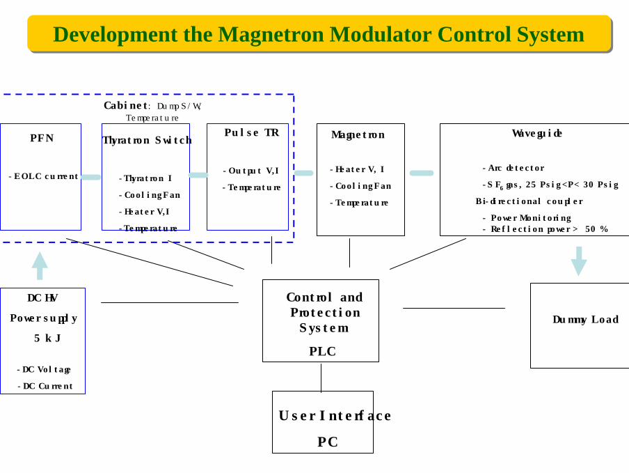
DC HV
Power supply
5 kJ
-DC Voltage
-DC Current
Control and Protection
System
PLC
PFN
-EOLC current
Thyratron Switch
-Thyratron I
-Cooling Fan
-Heater V,I
-Temperature
Pulse TR
-Output V,I
-Temperature
Magnetron
-Heater V, I
-Cooling Fan
-Temperature
User Interface
PC
Waveguide
-Arc detector
-SF6 gas, 25 Psig <P< 30 Psig
Bi-directional coupler
- Power Monitoring- Reflection power > 50 %
Dummy Load
Cabinet : Dump S/W, Temperature
Development the Magnetron Modulator Control SystemDevelopment the Magnetron Modulator Control System
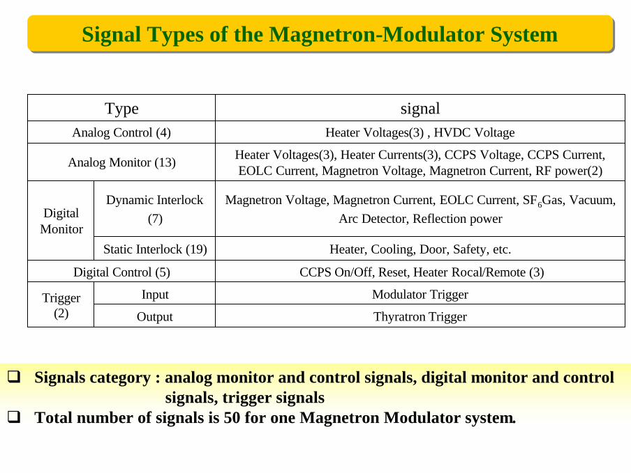
Heater Voltages(3) , HVDC VoltageAnalog Control (4)
Output
Input
Static Interlock (19)
Dynamic Interlock (7)
Thyratron Trigger
Modulator TriggerTrigger (2)
CCPS On/Off, Reset, Heater Rocal/Remote (3)Digital Control (5)
Magnetron Voltage, Magnetron Current, EOLC Current, SF6Gas, Vacuum, Arc Detector, Reflection powerDigital
Monitor
Heater, Cooling, Door, Safety, etc.
Heater Voltages(3), Heater Currents(3), CCPS Voltage, CCPS Current, EOLC Current, Magnetron Voltage, Magnetron Current, RF power(2)
signal
Analog Monitor (13)
Type
q Signals category : analog monitor and control signals, digital monitor and control signals, trigger signals
q Total number of signals is 50 for one Magnetron Modulator system.
Signal Types of the Magnetron-Modulator SystemSignal Types of the Magnetron-Modulator System

Pulsed Magnetron Pulsed Magnetron
CPI SFD-369
5, 28Heater V, I (V, A)
52Efficiency (%)
0.0008Duty1.68Peak Output Power (MW)
4Pulse Width (µs)
470Magnetron Impedance ( Ω)83Anode Current (A)
39Anode Voltage ( kV )
Average Output Power (kW)
Frequency (MHz ) 4900-5100
1.65
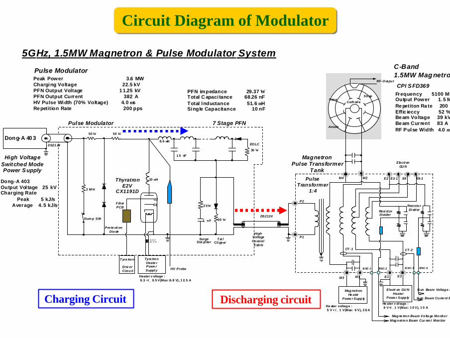
Dong-A 40 3
5GHz, 1.5MW Magnetron & Pulse Modulator SystemC-Band1.5MW Magnetron
Pulse Modulator
High VoltageSwitched ModePower S upply
Tyra tron
Driv er Circu it
Tyra tronHeate r Powe rSuppl y
MagnetronHe ater
Powe r Supp ly
Magne tron Beam Vo lta ge Monito rMagnetron Beam Cur ren t Mon itor
EOLC
Pro te cti on Diode
ThyratronE2V
CX1191D
Tai l Cli pper
SurgeDes pi ker
Pulse Transformer
1:4
Resi storDivider
Dong-A 403Output Vol tage 25 kVCharging Rate Peak 5 kJ/s Average 4.5 kJ/s
High VoltageCoaxial
Cab le
MagnetronPulse Transformer
Tank
SON. Yoongy u, '2 00 3. N ove mber. 1 9
Frequency 5100 MHzOutput Power 1.5 MWRe petiton Ra te 200 ppsEffic ieccy 52 %Be am Voltage 39 kVBe am Current 83 ARF Pulse Width 4.0 µs
Peak Power 3.6 MWCharging Voltage 22.5 kVPFN Output Voltage 1 1.25 kVPFN Output Current 382 AHV Pulse Width (70% Voltage) 4.0 µsRe petition Rate 200 pps
Pulse Modulator 7 Stage PFN
PFN impedance 29.37 ΩTotal C apaci tance 68.26 nFTotal Inductance 51.6 µHSingle Capacitance 10 nF
50 Ω
30 Ω
50 Ω
G2
G1
10 µH
6.3 V12. 5 A
CPI S FD369
1 nF
2 5 Ω
P1
P2
M2
M1M3
M4
E1
E2
E3
E2-1 E4 E4-1
CT-2
Electr on GU NHeater
Powe r Supp ly
ElectronGU N
Resisto rDi vider
Gun Beam Voltage Monito r
Gun Beam Curre nt Moni to r
50 Ω
CT-1
B NC -1 BNC-2 B NC-3 BNC -4
Heater v oltage : 6.3 +/_ 0. 5 V(Max :6. 8 V) , 1 2. 5 A
He ater voltage : 5 V + /_ 1 V(Max: 6 V), 2 8 A
He ater v ol tage : 9 V+/ _ 1 V(Max: 1 0 V), 1 0 A
F ilterPCB
2 MΩ
Dum p SW
8. 6 µH
1 0 nF
DS2124
DS21 24
RF-Outpu t
CathodeVane
Anode
Strap
HV Probe
Circuit Diagram of ModulatorCircuit Diagram of Modulator
Charging Circuit Discharging circuit

Design Parameters of ModulatorDesign Parameters of Modulator
Peak Voltage [kV] 45Peak Current [A] 96Load Impedance [O] 470HV Pulse Length [µs] 4Pulse Energy [J] 17.3Repetition Rate Max [Hz] 200Step-up Ratio 4PFN Charging Voltage [kV] 25PFN Impedance [O] 29.37PFN Section Cap [nF] 10PFN Section Inductance [µ H] 8.63PFN Section Number 7Charging Resistance [O] 100Thyratron ( CX1191D ) 8 MW, 35 kV, 500 A,

Specification of Pulse TransformerSpecification of Pulse Transformer
1Pulse Droop[%/µs]
0.2Rising Time [µs]
1 : 4Step of Ratio
200Pulse Repetition Rate [Hz]
3.2Plat Top pulse width [µs]
470Output Impedance [Ω]
45Secondary Voltage [kV]
96Secondary Current [A]
22.5Primary Voltage [kV]
375Primary Current [A]
Electrical Parameters of Pulse Transformer (In Air)Electrical Parameters of Pulse Transformer (In Air)
1.2681.271Primary Inductance [mH]
19.8520.342Secondary Inductance [mH]
Measured ValueModel calculated ValueItem
38.744.2Distributed Capacitance [pF]
42.279.3Leakage Inductance [µH]

7.5Winding length [cm]
53Mean Magnetic Path Length [cm]
10Primary Turn Number
1Distance between layers [cm]
800Effective magnetic Permeability
59.2Mean circumference between layers [cm]
0.746Total magnetic flux density swing [T]
0.88Core Packing factor [%]
76.2Magnetic Cross section Area[cm2]
40Secondary Turn Number
Parameters of Pulse TransformerParameters of Pulse Transformer
50 83
65
100
221
75
Core(50x50.4)
Primarywinding
Secondarywinding
186
200
90
Unit: mm
165

PFN & HV BoxPFN & HV Box
PFN HV Box
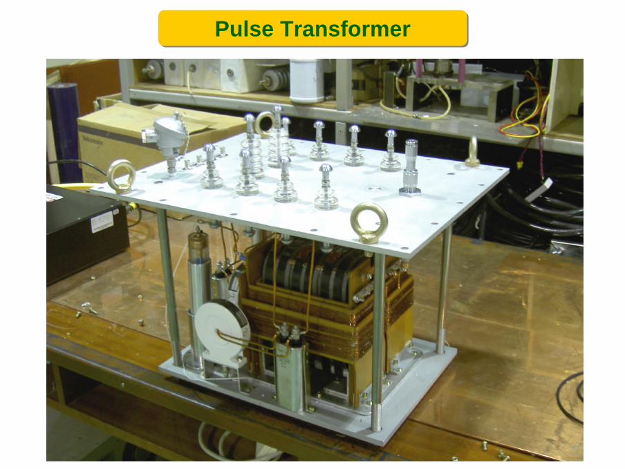
Pulse TransformerPulse Transformer
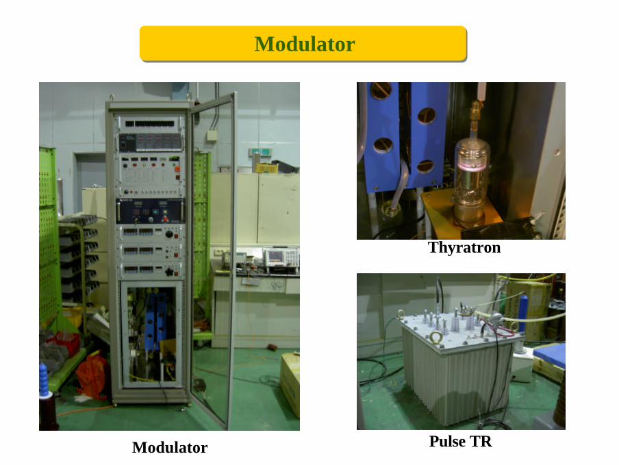
ModulatorModulator
Thyratron
Pulse TRModulator

Modulator Test SetupModulator Test Setup
472 Ω
Pulse TR
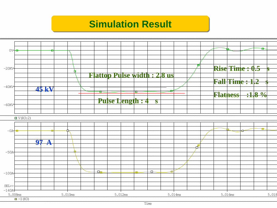
Simulation Result Simulation Result
Time
5.008ms 5.010ms 5.012ms 5.014ms 5.016ms 5.018ms-I(R3)
-100A
-50A
-0A
-140ASEL>>
V(R3:2)
-60KV
-40KV
-20KV
0V
Pulse Length : 4 μs
Rise Time : 0.5 μs
Fall Time : 1.2 μs
Flatness :1.8 %
Flattop Pulse width : 2.8 us
45 kV
97 A

Test Result Test Result
45 kV97 A
Rise time 0.4 us
Flatness 1.8 %
Flattop Pulse width 2.8 us

Conclusion & Future WorkConclusion & Future Work
1. LHCD 저출력 테스트를 위해 마그네트론, C-Band 도파관 시스템인 4-port circulator, Dry dummy load, Dual directional coupler, E-bend, Arc detector로구성했다.
2. 저출력 시험에 사용할 마이크로파 소스는 CPI에서 제작된 파워가 1.5 MW, 펄스폭 4 us인 마그네트론을 사용하고 있으며, 이 마그네트론을 운전하기 위한PFN방식의 모듈레이터를 설계 제작하였다.
3. 마크네트론 모듈레이터는 PLC를 이용한 Remote Control & Interlock 시스템으로 구성되도록 설계했다.
4. 제작된 PFN 모듈레이터를 LHCD 저출력 테스트용 5 GHz, 1.6 MW 마그네트론에 인가 하여 주파수와 마이크로웨이브 출력을 조사한다.