Embed Size (px)
Citation preview
SPRAYERS
ASSEMBLY, OPERATION &PARTS MANUAL FOR
5-IN-1 SPRAYER MODELS: GDL200, GDL400 & GDL600
AIR BLAST SPRAYER MODELS:APL200, APL400 & APL600
March 2007 Rev.
FORM: GDL5in1sprayer.QXD
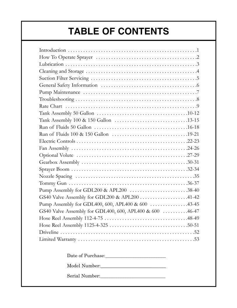
Introduction . . . . . . . . . . . . . . . . . . . . . . . . . . . . . . . . . . . . . . . . . . . . . . . . . . .1How To Operate Sprayer . . . . . . . . . . . . . . . . . . . . . . . . . . . . . . . . . . . . . . . .2Lubrication . . . . . . . . . . . . . . . . . . . . . . . . . . . . . . . . . . . . . . . . . . . . . . . . . . . .3Cleaning and Storage . . . . . . . . . . . . . . . . . . . . . . . . . . . . . . . . . . . . . . . . . . . .4Suction Filter Servicing . . . . . . . . . . . . . . . . . . . . . . . . . . . . . . . . . . . . . . . . . .5General Safety Information . . . . . . . . . . . . . . . . . . . . . . . . . . . . . . . . . . . . . .6Pump Maintenance . . . . . . . . . . . . . . . . . . . . . . . . . . . . . . . . . . . . . . . . . . . . .7Troubleshooting . . . . . . . . . . . . . . . . . . . . . . . . . . . . . . . . . . . . . . . . . . . . . . . .8Rate Chart . . . . . . . . . . . . . . . . . . . . . . . . . . . . . . . . . . . . . . . . . . . . . . . . . . . .9Tank Assembly 50 Gallon . . . . . . . . . . . . . . . . . . . . . . . . . . . . . . . . . . . .10-12Tank Assembly 100 & 150 Gallon . . . . . . . . . . . . . . . . . . . . . . . . . . . . .13-15Run of Fluids 50 Gallon . . . . . . . . . . . . . . . . . . . . . . . . . . . . . . . . . . . . .16-18Run of Fluids 100 & 150 Gallon . . . . . . . . . . . . . . . . . . . . . . . . . . . . . .19-21Electric Controls . . . . . . . . . . . . . . . . . . . . . . . . . . . . . . . . . . . . . . . . . . . .22-23Fan Assembly . . . . . . . . . . . . . . . . . . . . . . . . . . . . . . . . . . . . . . . . . . . . . .24-26Optional Volute . . . . . . . . . . . . . . . . . . . . . . . . . . . . . . . . . . . . . . . . . . . .27-29Gearbox Assembly . . . . . . . . . . . . . . . . . . . . . . . . . . . . . . . . . . . . . . . . . .30-31Sprayer Boom . . . . . . . . . . . . . . . . . . . . . . . . . . . . . . . . . . . . . . . . . . . . . .32-34Nozzle Spacing . . . . . . . . . . . . . . . . . . . . . . . . . . . . . . . . . . . . . . . . . . . . . . .35Tommy Gun . . . . . . . . . . . . . . . . . . . . . . . . . . . . . . . . . . . . . . . . . . . . . . .36-37Pump Assembly for GDL200 & APL200 . . . . . . . . . . . . . . . . . . . . . . .38-40GS40 Valve Assembly for GDL200 & APL200 . . . . . . . . . . . . . . . . . . .41-42Pump Assembly for GDL400, 600, APL400 & 600 . . . . . . . . . . . . . . .43-45GS40 Valve Assembly for GDL400, 600, APL400 & 600 . . . . . . . . . .46-47Hose Reel Assembly 112-4-75 . . . . . . . . . . . . . . . . . . . . . . . . . . . . . . . . .48-49Hose Reel Assembly 1125-4-325 . . . . . . . . . . . . . . . . . . . . . . . . . . . . . . .50-51Driveline . . . . . . . . . . . . . . . . . . . . . . . . . . . . . . . . . . . . . . . . . . . . . . . . . . . . .52Limited Warranty . . . . . . . . . . . . . . . . . . . . . . . . . . . . . . . . . . . . . . . . . . . . . .53
TABLE OF CONTENTS
Date of Purchase:__________________________
Model Number:____________________________
Serial Number:____________________________
INTRODUCTION
Page 1
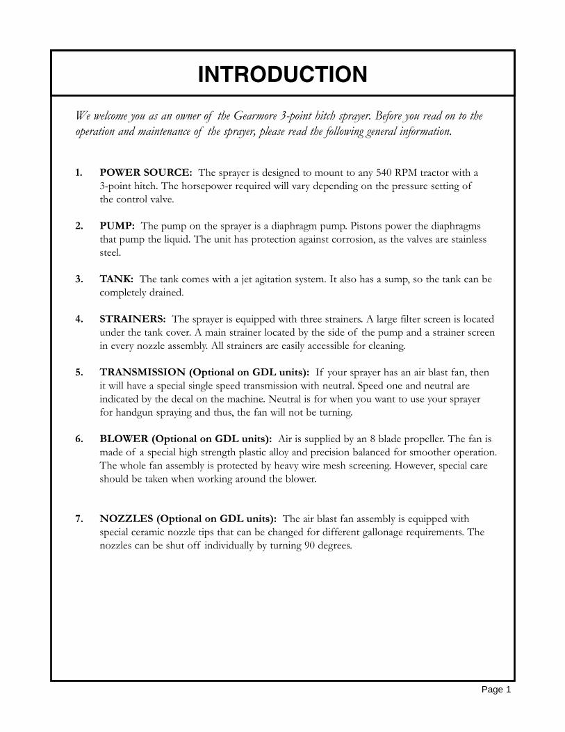
We welcome you as an owner of the Gearmore 3-point hitch sprayer. Before you read on to the operation and maintenance of the sprayer, please read the following general information.
1. POWER SOURCE: The sprayer is designed to mount to any 540 RPM tractor with a 3-point hitch. The horsepower required will vary depending on the pressure setting ofthe control valve.
2. PUMP: The pump on the sprayer is a diaphragm pump. Pistons power the diaphragms that pump the liquid. The unit has protection against corrosion, as the valves are stainless steel.
3. TANK: The tank comes with a jet agitation system. It also has a sump, so the tank can be completely drained.
4. STRAINERS: The sprayer is equipped with three strainers. A large filter screen is located under the tank cover. A main strainer located by the side of the pump and a strainer screenin every nozzle assembly. All strainers are easily accessible for cleaning.
5. TRANSMISSION (Optional on GDL units): If your sprayer has an air blast fan, then it will have a special single speed transmission with neutral. Speed one and neutral are indicated by the decal on the machine. Neutral is for when you want to use your sprayer for handgun spraying and thus, the fan will not be turning.
6. BLOWER (Optional on GDL units): Air is supplied by an 8 blade propeller. The fan is made of a special high strength plastic alloy and precision balanced for smoother operation.The whole fan assembly is protected by heavy wire mesh screening. However, special care should be taken when working around the blower.
7. NOZZLES (Optional on GDL units): The air blast fan assembly is equipped with special ceramic nozzle tips that can be changed for different gallonage requirements. The nozzles can be shut off individually by turning 90 degrees.
1. Connect sprayer to tractor 3-point hitch.
2. Connect up the P.T.O. driveshaft, after you have checked to make sure the driveshaft is not too long.
3. Check strainer screen, to make sure it is clean.
4. Check strainer shut-off valve, making sure the handle is in the open position.
5. Select transmission speed, if your sprayer is equipped with the air blast fan assembly.
6. Refer to calibration page to calibrate the sprayer. Set regulator pressure as required.Important - The pressure regulator adjusting knob must be unscrewed (turned to left) as far out as possible before operating sprayer. Then gradually screw in (turn to right) to desired pressure. Failure to operate in this manner could cause a sudden surge, which could damage the sprayer. By sliding the control handle left towards the pressure gauge,you can turn the valve one-half a turn to put the valve in bypass position. This would be used for mixing chemicals, etc. It takes the pressure off the pump and sends the liquid back to the tank. Turn the valve in the opposite direction for spraying. By sliding the handle away from the pressure gauge, you can adjust the pressure setting by turning the valve.
7. Engage tractor P.T.O. and run for a couple of minutes to make sure the jet agitator has mixed the chemicals thoroughly. Last, turn the control valve handles to the position required.Either right hand, left hand or both sides spraying.
Remember, it is always best to make a practice run with water to be sure you have the correct rates and coverage.
TO OPERATE SPRAYER
Page 2
1. DRIVESHAFT - The driveshaft comes not greased, so must be done before sprayer is put into use. After that, grease every 50 hours. It is also necessary, from time to time, to untelescope the driveshaft to clean and re-grease tubings.
2. TRANSMISSION - Observe the sight gauge, and install 90 weight transmission oil when necessary.
3. PUMP - The clear oil reservoir should be filled to the indicator mark. If oil is low, add engine oil, non-foaming, non-detergent 30 weight oil. The pump oil must be changed after the first 100 running hours and then at the end of every working season. (See pump page for more details.)
GENERAL MAINTENANCE
Carefully follow all instructions as stated in this operators manual. This includes lubrication,maintenance and operation of the sprayer. The sprayer was designed and built for years ofreliable service if properly cared for. However, an air blast sprayer is a high R.P.M. machine,thus, daily attention is required.
1. Check all bolts for tightness.
2. Check sprayer for leaks.
LUBRICATION
Page 3
1. Wash and flush out sprayer after completion of each phase of your spraying program.
2. Flush out sprayer when changing chemicals, if there is a possibility of incompatibility.
3. Clean sprayer very thoroughly before storing at the end of the spraying season. If you are in a cold climate, final rinse should be with a sufficiently concentrated anti-freeze to prevent freeze-up in areas that were not thoroughly drained.
4. Check sprayer over for needed repairs before time to spray again.
5. Preparing the sprayer for use in the Spring means completion of all needed repairs,installation of all drain plugs and checking sprayer for leaks with a tank of water.
SAFETY TIPS
Sprayer should be operated only by qualified persons.
Always fill sprayer slowly to avoid spillage.
When starting sprayer, maintain a safe distance from moving parts.
Never run P.T.O. at speeds in excess of 540 R.P.M.
Do not make adjustments when sprayer is running, unless specifically recommended.
Never leave sprayer unattended while it is running.
Keep hands, feet and clothing away from all moving parts.
Handle chemicals carefully; follow the manufacturer's directions for mixing and applying chemicals.
CLEANING & STORAGE
Page 4
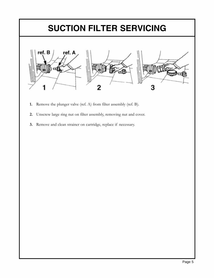
1. Remove the plunger valve (ref. A) from filter assembly (ref. B).
2. Unscrew large ring nut on filter assembly, removing nut and cover.
3. Remove and clean strainer on cartridge, replace if necessary.
SUCTION FILTER SERVICING
Page 5
Use of pressure relief device, on the discharge side of pump, is required to prevent damage from pressure build-up, if the discharge is closed or blocked, while the power source is still running.
Do not operate pump above recommended R.P.M.
Do not pump at pressure higher than the maximum recommended for the pump (see specifications).
Operate pump between 45o and 145o F liquid temperatures.
Make certain that the power source conforms to the requirements of your equipment.
Provide adequate protection in guarding around the moving parts, such as the shaft and pulleys.
Disconnect power before servicing.
Release all pressure within the system before servicing any component.
Drain all liquids from the system before servicing.
Secure the discharge lines before starting the pump. An unsecured discharge line may whip, causing personal injury and/or property damage.
Check hoses for weak or worn condition before each use. Make certain that all connections are tight and secure.
Periodically inspect the pump and the system components. Perform routine maintenance as required (see maintenance section).
Do not operate a gasoline engine in an enclosed area. Be sure the area is well ventilated.
Use only pipe, hose and fittings rated for maximum rated pressure of pump or pressure at which pressure relief valve is set. Check with local supplier for proper pressure rating. (Do not use used pipe!)
Do not use these pumps for pumping water or other liquids for human or animal consumption.
GENERAL SAFETY INFORMATION
Page 6
WARNING - Do not pump flammable or explosive fluids such asgasoline, fuel oil, kerosene, etc. Do not use in explosive atmos-pheres. The pump should be used only with liquids compatible withthe pump component materials. Failure to follow this warning mayresult in personal injury and / or property damage and will void theproduct warranty.
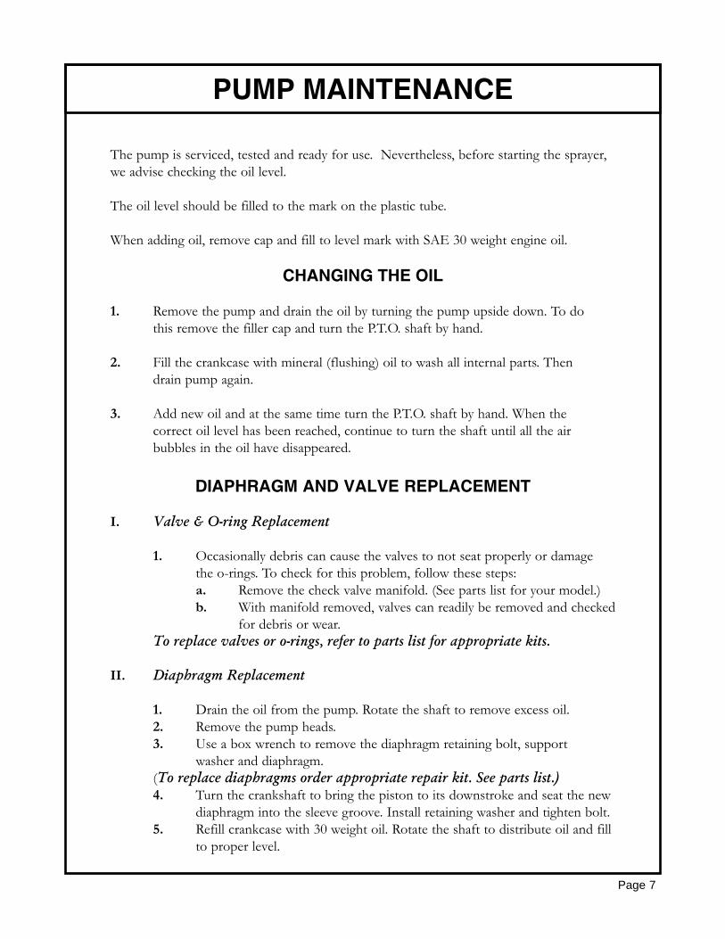
The pump is serviced, tested and ready for use. Nevertheless, before starting the sprayer,we advise checking the oil level.
The oil level should be filled to the mark on the plastic tube.
When adding oil, remove cap and fill to level mark with SAE 30 weight engine oil.
CHANGING THE OIL
1. Remove the pump and drain the oil by turning the pump upside down. To do this remove the filler cap and turn the P.T.O. shaft by hand.
2. Fill the crankcase with mineral (flushing) oil to wash all internal parts. Then drain pump again.
3. Add new oil and at the same time turn the P.T.O. shaft by hand. When the correct oil level has been reached, continue to turn the shaft until all the air bubbles in the oil have disappeared.
DIAPHRAGM AND VALVE REPLACEMENT
I. Valve & O-ring Replacement
1. Occasionally debris can cause the valves to not seat properly or damage the o-rings. To check for this problem, follow these steps:a. Remove the check valve manifold. (See parts list for your model.)b. With manifold removed, valves can readily be removed and checked
for debris or wear.To replace valves or o-rings, refer to parts list for appropriate kits.
II. Diaphragm Replacement
1. Drain the oil from the pump. Rotate the shaft to remove excess oil.2. Remove the pump heads.3. Use a box wrench to remove the diaphragm retaining bolt, support
washer and diaphragm.(To replace diaphragms order appropriate repair kit. See parts list.)4. Turn the crankshaft to bring the piston to its downstroke and seat the new
diaphragm into the sleeve groove. Install retaining washer and tighten bolt.5. Refill crankcase with 30 weight oil. Rotate the shaft to distribute oil and fill
to proper level.
Page 7
PUMP MAINTENANCE
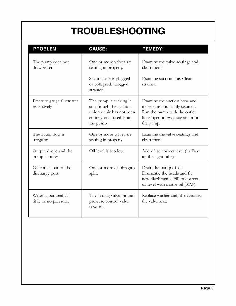
The pump does not One or more valves are Examine the valve seatings anddraw water. seating improperly. clean them.
Suction line is plugged Examine suction line. Cleanor collapsed. Clogged strainer.strainer.
Pressure gauge fluctuates The pump is sucking in Examine the suction hose and excessively. air through the suction make sure it is firmly secured.
union or air has not been Run the pump with the outletentirely evacuated from hose open to evacuate air fromthe pump. the pump.
The liquid flow is One or more valves are Examine the valve seatings andirregular. seating improperly. clean them.
Output drops and the Oil level is too low. Add oil to correct level (halfwaypump is noisy. up the sight tube).
Oil comes out of the One or more diaphragms Drain the pump of oil.discharge port. split. Dismantle the heads and fit
new diaphragms. Fill to correctoil level with motor oil (30W).
Water is pumped at The sealing valve on the Replace washer and, if necessary,little or no pressure. pressure control valve the valve seat.
is worn.
TROUBLESHOOTING
Page 8
PROBLEM: CAUSE: REMEDY:
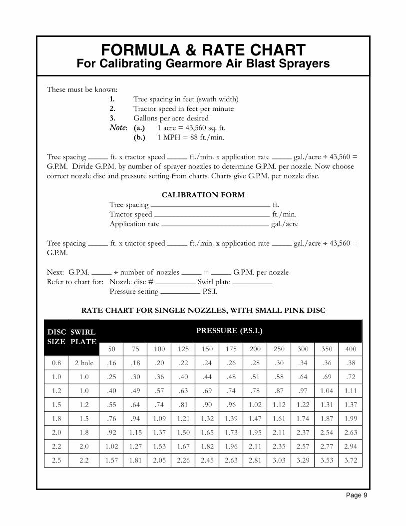
These must be known:1. Tree spacing in feet (swath width)2. Tractor speed in feet per minute3. Gallons per acre desiredNote: (a.) 1 acre = 43,560 sq. ft.
(b.) 1 MPH = 88 ft./min.
Tree spacing _____ ft. x tractor speed _____ ft./min. x application rate _____ gal./acre ÷ 43,560 = G.P.M. Divide G.P.M. by number of sprayer nozzles to determine G.P.M. per nozzle. Now choose correct nozzle disc and pressure setting from charts. Charts give G.P.M. per nozzle disc.
CALIBRATION FORMTree spacing ______________________________ ft.Tractor speed _____________________________ ft./min.Application rate ___________________________ gal./acre
Tree spacing _____ ft. x tractor speed _____ ft./min. x application rate _____ gal./acre ÷ 43,560 = G.P.M.
Next: G.P.M. _____ ÷ number of nozzles _____ = _____ G.P.M. per nozzleRefer to chart for: Nozzle disc # __________ Swirl plate __________
Pressure setting __________ P.S.I.
RATE CHART FOR SINGLE NOZZLES, WITH SMALL PINK DISC
Page 9
FORMULA & RATE CHARTFor Calibrating Gearmore Air Blast Sprayers
CSIDEZIS
LRIWSETALP
).I.S.P(ERUSSERP
05 57 001 521 051 571 002 052 003 053 004
8.0 eloh2 61. 81. 02. 22. 42. 62. 82. 03. 43. 63. 83.
0.1 0.1 52. 03. 63. 04. 44. 84. 15. 85. 46. 96. 27.
2.1 0.1 04. 94. 75. 36. 96. 47. 87. 78. 79. 40.1 11.1
5.1 2.1 55. 46. 47. 18. 09. 69. 20.1 21.1 22.1 13.1 73.1
8.1 5.1 67. 49. 90.1 12.1 23.1 93.1 74.1 16.1 47.1 78.1 99.1
0.2 8.1 29. 51.1 73.1 05.1 56.1 37.1 59.1 11.2 73.2 45.2 36.2
2.2 0.2 20.1 72.1 35.1 76.1 28.1 69.1 11.2 53.2 75.2 77.2 49.2
5.2 2.2 75.1 18.1 50.2 62.2 54.2 36.2 18.2 30.3 92.3 35.3 27.3
DISCSIZE
SWIRLPLATE
PRESSURE (P.S.I.)
Page 10
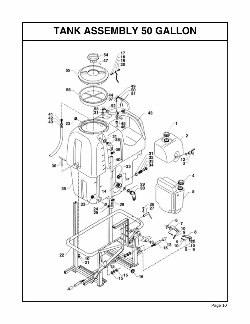
TANK ASSEMBLY 50 GALLON
REF # QTY. PART NO. DESCRIPTION
1 1 0600187 Lid2 1 0600189 Tank, Handwash3 1 0600190 Drain Valve4 1 0600187 Lid5 1 0600182 Tank, Flush6 2 0100107 Plate7 1 0101477 Bracket8 1 0101478 Bracket9 4 1800036 Bolt M10 x 2510 6 1800130 Washer D.1011 2 1300036 Fitting Assembly12 1 0600191 Gasket13 4 2100135 Bushing 28.4 x 22.414 1 1400009 Nut, Ring15 2 2100009 Lift Pin Assembly16 4 2900001 Protector D.2217 1 1800177 Nut M518 1 1800113 Washer 6.4 x 12.519 1 1400007 Chain20 1 1800003 Bolt M5 x 1221 2 1800186 Nut M.1022 1 0101454 Frame23 3 1400001 Nut24 1 0600014 Gasket25 1 1400130 Elbow26 1 2100001 Hair Pin27 1 0100203 Pin D.1828 1 1800350 Clamp D2.9 x 929 1 1700015 Gasket30 1 1400212 Drain Valve31 3 1700001 Gasket 33 x 21 x 232 1 1400002 Nipple33 1 1700021 Gasket 19 x 434 1 1400124 Plug35 1 0600184 Tank 50 Gallon36 2 0101476 T Handle37 1 1400204 Nozzle D.1.538 1 1400130 Elbow39 1 0600051 Clamp
Continued....
TANK ASSEMBLY 50 GALLON
Page 11
REF # QTY. PART NO. DESCRIPTION
40 As Req'd 12X17 Hose 12 x 17 Per Foot41 1 1400192 Fitting42 1 1500007 Clamp43 As Req'd 19X26 Hose 19 x 26 Per Foot44 1 1700006 O-Ring 36 x 26 x 545 1 0600192 Strap46 1 1400074 Agitator47 1 2100143 Hook48 1 0600193 Knob49 1 1400075 Elbow50 1 1700010 Gasket 18 x 12 x 251 As Req'd 10X19 Hose 10 x 19 Per Foot52 1 1500003 Clamp53 1 1400062 Elbow D.2054 1 0600007 Lid, Vent55 1 00.723.010 Lid56 1 00.646.000 Strainer Basket
TANK ASSEMBLY 50 GALLON
Page 12
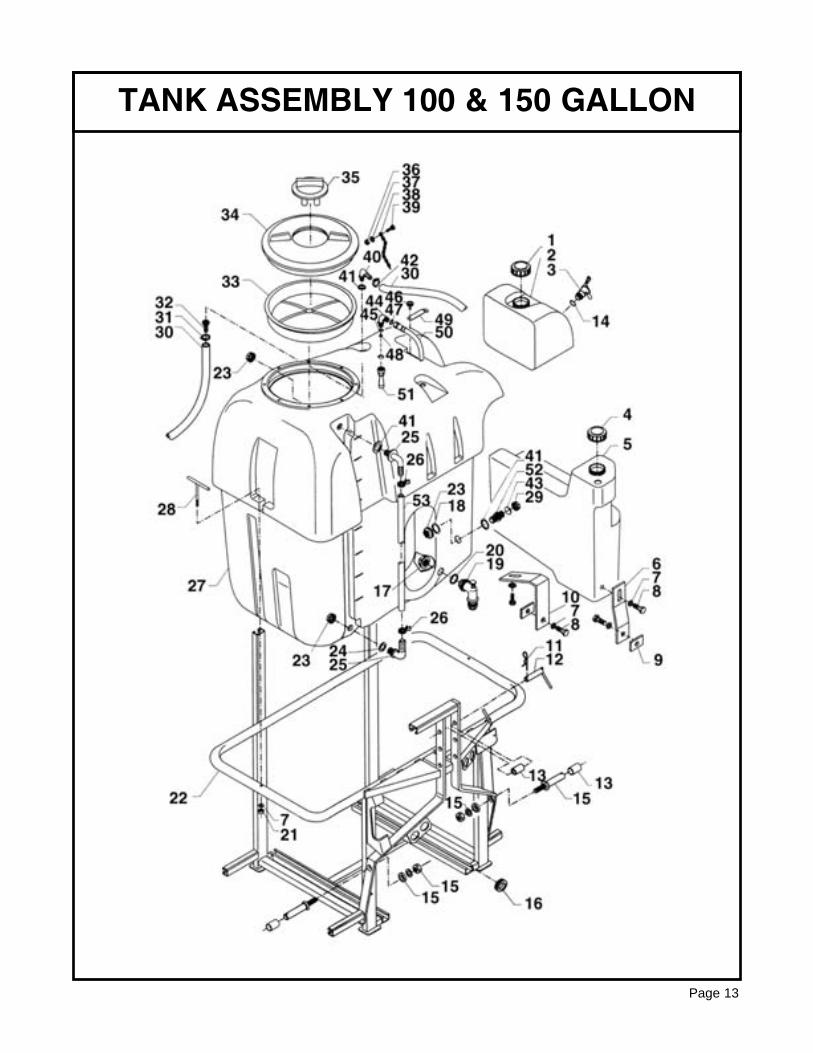
TANK ASSEMBLY 100 & 150 GALLON
Page 13
REF # QTY. PART NO. DESCRIPTION
1 1 0600187 Lid2 1 0600189 Tank, Handwash3 1 0600190 Valve, Drain4 1 0600187 Lid5 1 0600167 Tank, Flush6 1 0101488 Support7 6 1800130 Washer M.108 4 1800036 Bolt M10 x 259 2 0100107 Plate, Threaded10 1 0101487 Support11 1 2100001 Hair Pin12 1 0100203 Pin D.1813 4 2100135 Bushing 28.4 x 22.4 L=4514 1 0600191 Gasket15 2 2100007 Lift Pin Assembly16 4 2900001 Garment, Rubber D.2217 1 1400009 Ring Nut18 1 0600014 Gasket19 1 1400212 Drain Plug Assembly20 1 1700015 Gasket 57.5 x 40 x 321 2 1800186 Nut M1022 1 0101450 Frame23 3 1400001 Ring Nut24 1 2600009 Gasket25 2 1400130 Elbow26 2 0600051 Clamp27 1 0600185 Tank 100 Gallon27 1 0600186 Tank 150 Gallon28 2 0101476 T Handle29 1 1400124 Plug30 As Req'd 19X26 Hose 19 x 26 Per Foot31 1 1500007 Clamp32 1 1400192 Nipple D.2033 1 0600023 Strainer Basket34 1 0600006 Lid 17 7/8" O.D.35 1 0600007 Vent Lid36 1 1800177 Nut M537 1 1800113 Washer 6.4 x 12.5
Continued....
TANK ASSEMBLY 100 & 150 GALLON
Page 14
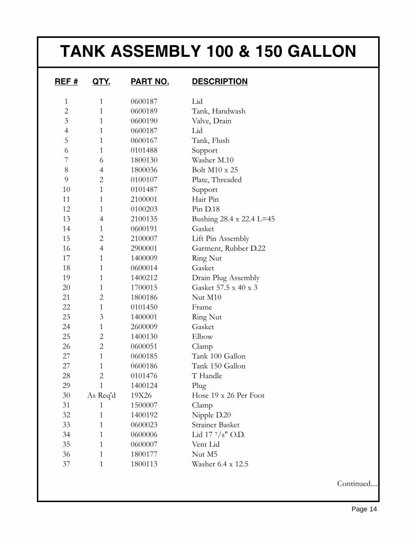
REF # QTY. PART NO. DESCRIPTION
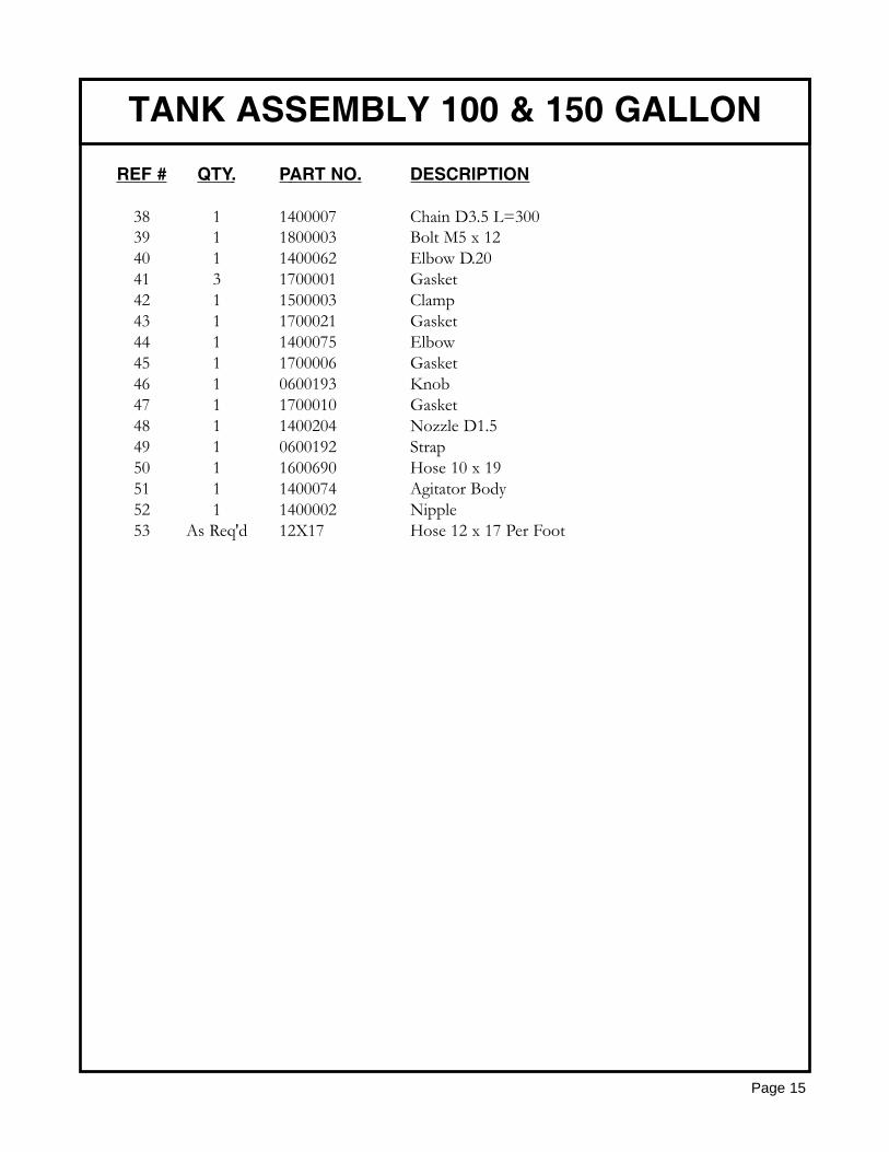
38 1 1400007 Chain D3.5 L=30039 1 1800003 Bolt M5 x 1240 1 1400062 Elbow D.2041 3 1700001 Gasket42 1 1500003 Clamp43 1 1700021 Gasket44 1 1400075 Elbow45 1 1700006 Gasket46 1 0600193 Knob47 1 1700010 Gasket48 1 1400204 Nozzle D1.549 1 0600192 Strap50 1 1600690 Hose 10 x 1951 1 1400074 Agitator Body52 1 1400002 Nipple53 As Req'd 12X17 Hose 12 x 17 Per Foot
TANK ASSEMBLY 100 & 150 GALLON
Page 15
RUN OF FLUIDS 50 GALLON
Page 16
REF # QTY. PART NO. DESCRIPTION
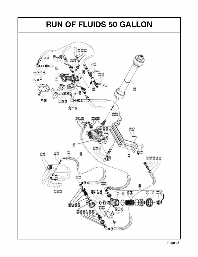
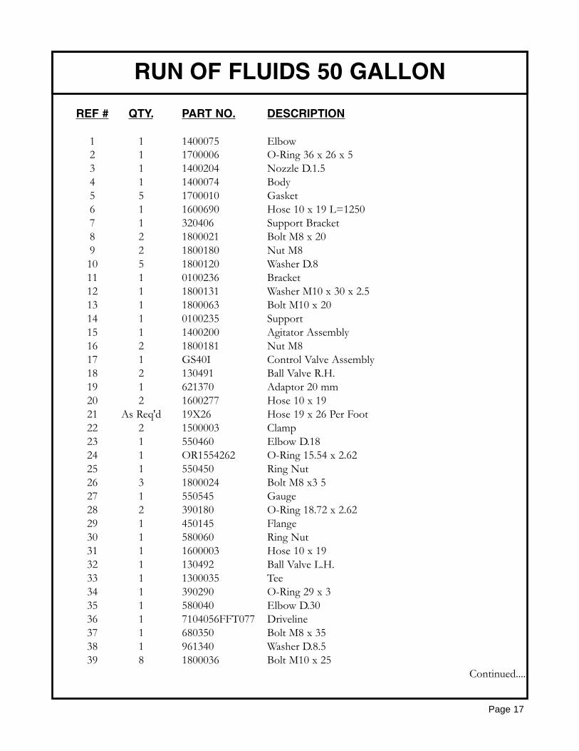
1 1 1400075 Elbow2 1 1700006 O-Ring 36 x 26 x 53 1 1400204 Nozzle D.1.54 1 1400074 Body5 5 1700010 Gasket6 1 1600690 Hose 10 x 19 L=12507 1 320406 Support Bracket8 2 1800021 Bolt M8 x 209 2 1800180 Nut M810 5 1800120 Washer D.811 1 0100236 Bracket12 1 1800131 Washer M10 x 30 x 2.513 1 1800063 Bolt M10 x 2014 1 0100235 Support15 1 1400200 Agitator Assembly16 2 1800181 Nut M817 1 GS40I Control Valve Assembly18 2 130491 Ball Valve R.H.19 1 621370 Adaptor 20 mm20 2 1600277 Hose 10 x 1921 As Req'd 19X26 Hose 19 x 26 Per Foot22 2 1500003 Clamp23 1 550460 Elbow D.1824 1 OR1554262 O-Ring 15.54 x 2.6225 1 550450 Ring Nut26 3 1800024 Bolt M8 x3 527 1 550545 Gauge28 2 390180 O-Ring 18.72 x 2.6229 1 450145 Flange30 1 580060 Ring Nut31 1 1600003 Hose 10 x 1932 1 130492 Ball Valve L.H.33 1 1300035 Tee34 1 390290 O-Ring 29 x 335 1 580040 Elbow D.3036 1 7104056FFT077 Driveline37 1 680350 Bolt M8 x 3538 1 961340 Washer D.8.539 8 1800036 Bolt M10 x 25
Continued....
RUN OF FLUIDS 50 GALLON
Page 17
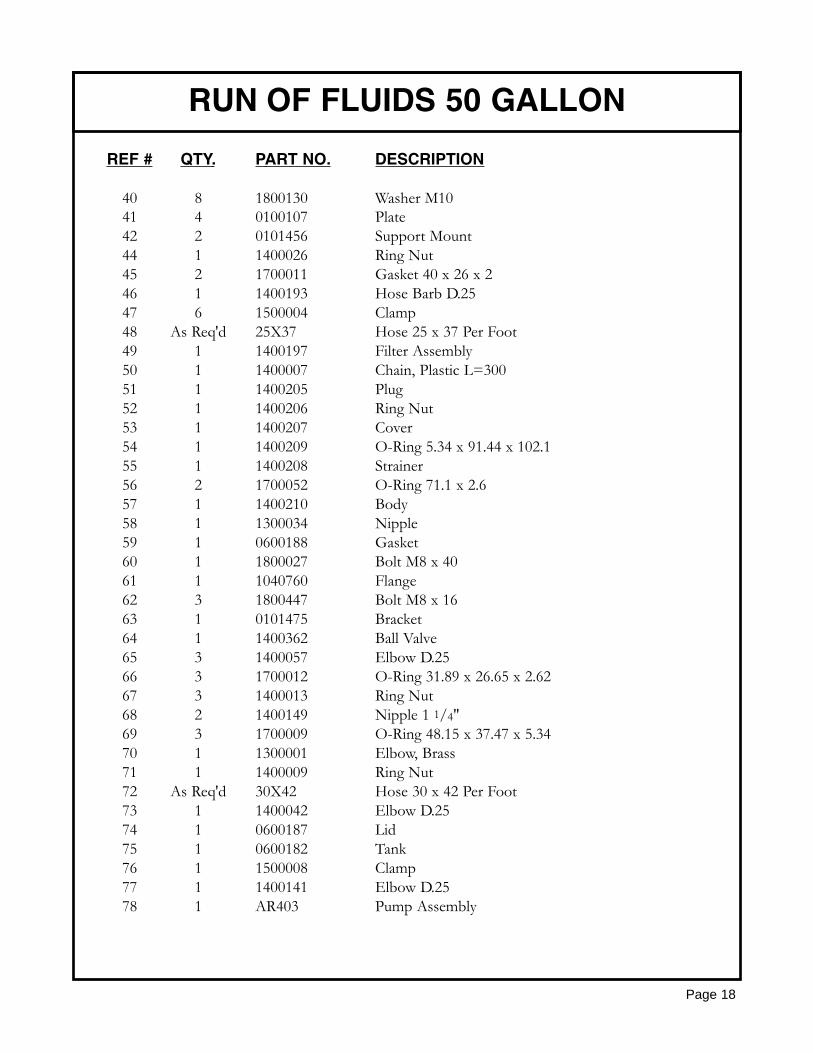
REF # QTY. PART NO. DESCRIPTION
40 8 1800130 Washer M1041 4 0100107 Plate42 2 0101456 Support Mount44 1 1400026 Ring Nut45 2 1700011 Gasket 40 x 26 x 246 1 1400193 Hose Barb D.2547 6 1500004 Clamp48 As Req'd 25X37 Hose 25 x 37 Per Foot49 1 1400197 Filter Assembly50 1 1400007 Chain, Plastic L=30051 1 1400205 Plug52 1 1400206 Ring Nut53 1 1400207 Cover54 1 1400209 O-Ring 5.34 x 91.44 x 102.155 1 1400208 Strainer56 2 1700052 O-Ring 71.1 x 2.657 1 1400210 Body58 1 1300034 Nipple59 1 0600188 Gasket60 1 1800027 Bolt M8 x 4061 1 1040760 Flange62 3 1800447 Bolt M8 x 1663 1 0101475 Bracket64 1 1400362 Ball Valve65 3 1400057 Elbow D.2566 3 1700012 O-Ring 31.89 x 26.65 x 2.6267 3 1400013 Ring Nut68 2 1400149 Nipple 1 1/4"69 3 1700009 O-Ring 48.15 x 37.47 x 5.3470 1 1300001 Elbow, Brass71 1 1400009 Ring Nut72 As Req'd 30X42 Hose 30 x 42 Per Foot73 1 1400042 Elbow D.2574 1 0600187 Lid75 1 0600182 Tank76 1 1500008 Clamp77 1 1400141 Elbow D.2578 1 AR403 Pump Assembly
RUN OF FLUIDS 50 GALLON
Page 18
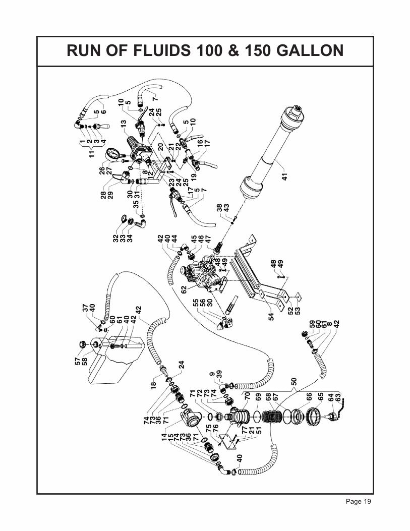
RUN OF FLUIDS 100 & 150 GALLON
Page 19
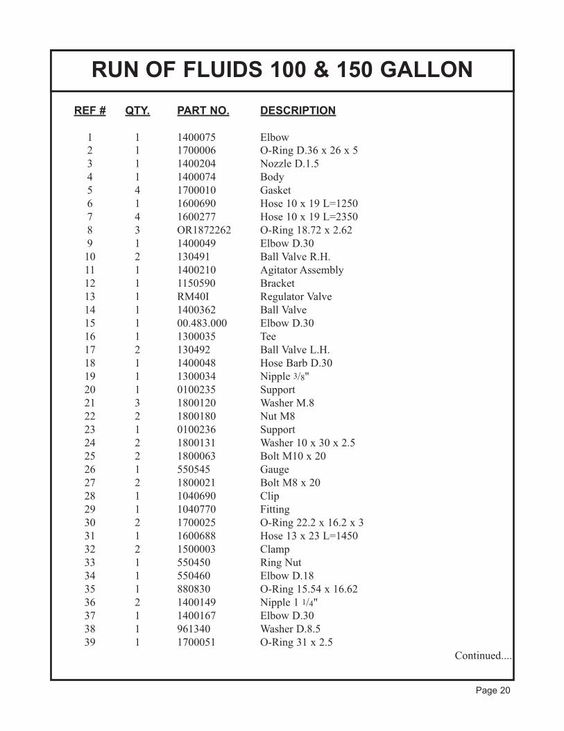
REF # QTY. PART NO. DESCRIPTION
1 1 1400075 Elbow
2 1 1700006 O-Ring D.36 x 26 x 5
3 1 1400204 Nozzle D.1.5
4 1 1400074 Body
5 4 1700010 Gasket
6 1 1600690 Hose 10 x 19 L=1250
7 4 1600277 Hose 10 x 19 L=2350
8 3 OR1872262 O-Ring 18.72 x 2.62
9 1 1400049 Elbow D.30
10 2 130491 Ball Valve R.H.
11 1 1400210 Agitator Assembly
12 1 1150590 Bracket
13 1 RM40I Regulator Valve
14 1 1400362 Ball Valve
15 1 00.483.000 Elbow D.30
16 1 1300035 Tee
17 2 130492 Ball Valve L.H.
18 1 1400048 Hose Barb D.30
19 1 1300034 Nipple 3/8"
20 1 0100235 Support
21 3 1800120 Washer M.8
22 2 1800180 Nut M8
23 1 0100236 Support
24 2 1800131 Washer 10 x 30 x 2.5
25 2 1800063 Bolt M10 x 20
26 1 550545 Gauge
27 2 1800021 Bolt M8 x 20
28 1 1040690 Clip
29 1 1040770 Fitting
30 2 1700025 O-Ring 22.2 x 16.2 x 3
31 1 1600688 Hose 13 x 23 L=1450
32 2 1500003 Clamp
33 1 550450 Ring Nut
34 1 550460 Elbow D.18
35 1 880830 O-Ring 15.54 x 16.62
36 2 1400149 Nipple 1 1/4"
37 1 1400167 Elbow D.30
38 1 961340 Washer D.8.5
39 1 1700051 O-Ring 31 x 2.5
Continued....
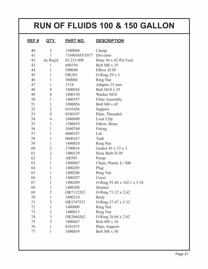
RUN OF FLUIDS 100 & 150 GALLON
Page 20
REF # QTY. PART NO. DESCRIPTION
40 5 1500004 Clamp
41 1 7104056FFT077 Driveline
42 As Req'd 02.215.000 Hose 30 x 42 Per Foot
43 1 680350 Bolt M8 x 35
44 1 580040 Elbow D.30
45 1 OR293 O-Ring 29 x 3
46 1 580060 Ring Nut
47 1 1518 Adapter 25 mm
48 8 1800036 Bolt M10 x 25
49 8 1800130 Washer M10
50 1 1400197 Filter Assembly
51 1 1800056 Bolt M8 x 45
52 2 0101456 Support
53 4 0100107 Plate, Threaded
54 4 1040690 Lock Clip
55 1 1300019 Elbow, Brass
56 1 1040760 Fitting
57 1 0600187 Lid
58 1 0600167 Tank
59 1 1400024 Ring Nut
60 2 1700016 Gasket 45 x 33 x 3
61 2 1400129 Hose Barb D.30
62 1 AR503 Pump
63 1 1400007 Chain, Plastic L=300
64 1 1400205 Plug
65 1 1400206 Ring Nut
66 1 1400207 Cover
67 1 1400209 O-Ring 91.44 x 102.1 x 5.34
68 1 1400208 Strainer
69 2 OR7112262 O-Ring 71.12 x 2.62
70 1 1400210 Body
71 3 OR3747533 O-Ring 37.47 x 5.33
72 1 1400009 Ring Nut
73 3 1400013 Ring Nut
74 3 OR2664262 O-Ring 26.64 x 2.62
75 3 1800447 Bolt M8 x 16
76 1 0101475 Plate, Support
77 1 1800039 Bolt M8 x 50
RUN OF FLUIDS 100 & 150 GALLON
Page 21
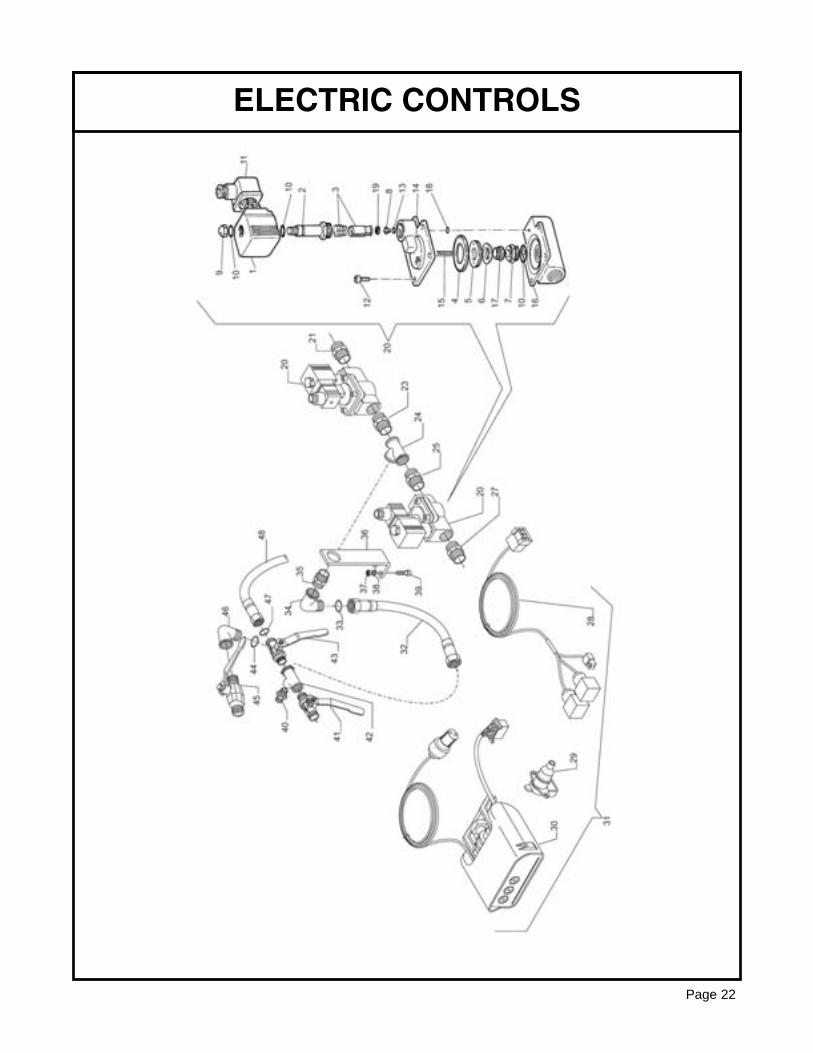
ELECTRIC CONTROLS
Page 22
REF # QTY. PART NO. DESCRIPTION1 1 OCLR73-952 Complete Coil2 1 OCLR73-953 Fixed Core3 1 OCLR73-954 Mobile Core4 1 OCLR73-957 Viton Membrane5 1 OCLR73-958 Plate6 1 OCLR73-958A Taper Gasket7 1 OCLR73-959 Stainless Steel Seat8 1 OCLR73-955 Nozzle9 1 OCLR73-951 Cap Nut10 1 OCLR73-709 O-Ring 205611 1 OCLR73-950 Connector12 1 OCLR59-711 Screw13 1 OCLR25-471 O-Ring 10414 1 OCLR73-956 Cap15 1 OCLR58-542 Spring for Anti-Drip16 1 OCLR73-960 Body17 1 OCLR73-961 Screw18 1 OCLR1-2015 Ring OR 201519 1 OCLR73-954A Gasket20 2 0800285 Solenoid Electric Valve21 1 1300021 Brass Nipple 1/2-1/223 1 1300021 Brass Nipple 1/2-1/224 1 1300106 Connector25 1 1300021 Brass Nipple 1/2-1/227 1 1300021 Brass Nipple 1/2-1/229 1 SA-905048 Feeding Socket31 1 0200017 Box Plt OCLL 2A+G Saver Pump C/C Masotti32 1 1600303 Hose 10 x 19 80 Bar L=300 RA33 1 1700010 Gasket 18 x 12 x 2 White34 1 1300001 Brass Elbow MF 1/2-1/235 1 1300021 Brass Nipple 1/2-1/236 1 0101751 Support Electric Command37 2 1800180 Nut M8 UNI 5587 6.8 Galvanized38 2 1800120 Flat Washer UNI 6592 M.8 Galvanized39 2 1800018 Bolt TCEI M8 x 20 UNI 5931 8.8 Galvanized40 1 1300034 Nipple MM 3/8-3/841 1 1300010 Valve LH 1/2-5/8 A.526442 1 1300035 Connector 3/8-3/8-3/843 1 1300009 Cock RH 1/2-3/8 "Meteor" A.526344 1 1700010 Gasket 18 x 12 x 2 White45 1 1300009 Cock RH 1/2-3/8 "Meteor" A.526346 1 1300001 Brass Elbow MF 1/2-1/247 1 1700010 Gasket 18 x 12 x 2 White48 1 1600690 Hose Co. PVC 10 x 19 80 Bar L=1250
ELECTRIC CONTROLS
Page 23
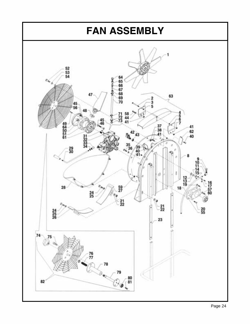
FAN ASSEMBLY
Page 24
REF # QTY. PART NO. DESCRIPTION1 1 0100619 Fan D.700, 100 & 150 Gallon1 1 0101093 Fan D.600, 50 Gallon2 1 1800136 Bolt M8 x 1003 1 0101485 Front Plate 50 Gallon3 1 0101468 Front Plate 100 & 150 Gallon4 2 0101465 Shield5 2 1800120 Washer M86 1 0101467 Rear Plate7 7 1800181 Nut M88 1 0100614 Support9 2 0100097 Blind Plug10 2 1700021 Gasket 19 x 411 2 1300001 Elbow, Brass12 4 1800150 Washer M1413 4 0101034 Bushing 19.2 x 27 x 1114 8 0800003 Body, 50 Gallon14 10 0800003 Body, 100 & 150 Gallon15 8 OR992262 O-Ring 9.92 x 2.62, 50 Gallon15 10 OR992262 O-Ring 9.92 x 2.62, 100 & 150 Gallon16 16 1800002 Bolt M5 x 16, 50 Gallon16 20 1800002 Bolt M5 x 16, 100 & 150 Gallon17 8 0800004 Nozzle Clamp, 50 Gallon17 10 0800004 Nozzle Clamp, 100 & 150 Gallon18 2 2000031 Tube, D.20 x 1.2, 50 Gallon18 2 2000049 Tube, D.20 x 1.2, 100 & 150 Gallon19 6 1800036 Bolt M10 x 2520 4 1800038 Bolt M10 x 3521 2 1800185 Nut M1022 12 1800130 Washer M1023 2 0101486 Support Plate L=560 50 Gallon23 2 0101466 Support Plate L=770 100 & 150 Gallon24 2 1800036 Bolt M10 x 2525 4 1800130 Washer M1026 1 0100264 Fin R. H.27 1 0100265 Fin L. H.28 1 1400237 Trash Shield29 1 1800413 Knob30 1 0100618 Lever31 1 1800417 Key 6 x 6 x 3032 1 0300099 Gearbox33 1 0100253 Bushing D.12 x 3034 1 1800190 Nut M1235 4 1800042 Bolt M10 x 5536 4 1800130 Washer M1037 5 1800179 Nut M638 10 1800021 Bolt M8 x 2039 4 0101469 Side Fin R.H.40 8 1800021 Bolt M8 x 20
Continued....
FAN ASSEMBLY
Page 25
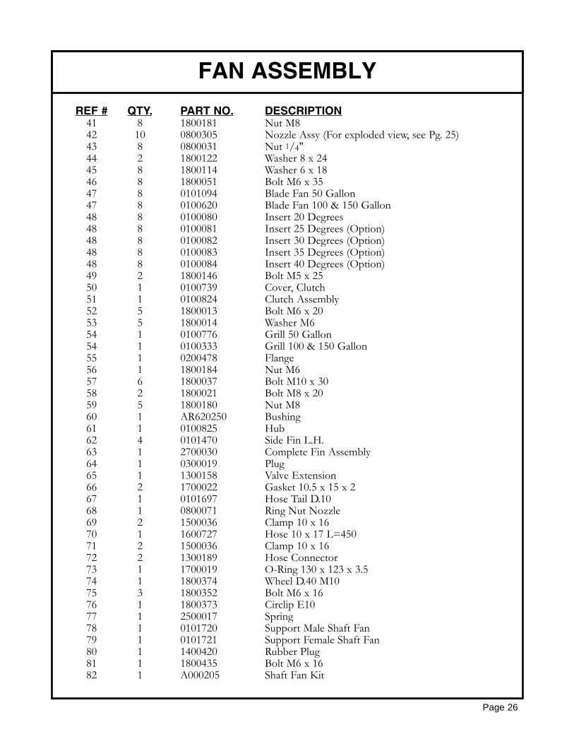
REF # QTY. PART NO. DESCRIPTION41 8 1800181 Nut M842 10 0800305 Nozzle Assy (For exploded view, see Pg. 25)43 8 0800031 Nut 1/4"44 2 1800122 Washer 8 x 2445 8 1800114 Washer 6 x 1846 8 1800051 Bolt M6 x 3547 8 0101094 Blade Fan 50 Gallon47 8 0100620 Blade Fan 100 & 150 Gallon48 8 0100080 Insert 20 Degrees48 8 0100081 Insert 25 Degrees (Option)48 8 0100082 Insert 30 Degrees (Option)48 8 0100083 Insert 35 Degrees (Option)48 8 0100084 Insert 40 Degrees (Option)49 2 1800146 Bolt M5 x 2550 1 0100739 Cover, Clutch51 1 0100824 Clutch Assembly52 5 1800013 Bolt M6 x 2053 5 1800014 Washer M654 1 0100776 Grill 50 Gallon54 1 0100333 Grill 100 & 150 Gallon55 1 0200478 Flange56 1 1800184 Nut M657 6 1800037 Bolt M10 x 3058 2 1800021 Bolt M8 x 2059 5 1800180 Nut M860 1 AR620250 Bushing61 1 0100825 Hub62 4 0101470 Side Fin L.H.63 1 2700030 Complete Fin Assembly64 1 0300019 Plug65 1 1300158 Valve Extension66 2 1700022 Gasket 10.5 x 15 x 267 1 0101697 Hose Tail D.1068 1 0800071 Ring Nut Nozzle69 2 1500036 Clamp 10 x 1670 1 1600727 Hose 10 x 17 L=45071 2 1500036 Clamp 10 x 1672 2 1300189 Hose Connector73 1 1700019 O-Ring 130 x 123 x 3.574 1 1800374 Wheel D.40 M1075 3 1800352 Bolt M6 x 1676 1 1800373 Circlip E1077 1 2500017 Spring78 1 0101720 Support Male Shaft Fan79 1 0101721 Support Female Shaft Fan80 1 1400420 Rubber Plug81 1 1800435 Bolt M6 x 1682 1 A000205 Shaft Fan Kit
FAN ASSEMBLY
Page 26
OPTIONAL VOLUTE
Page 27
28
REF # QTY. PART NO. DESCRIPTION
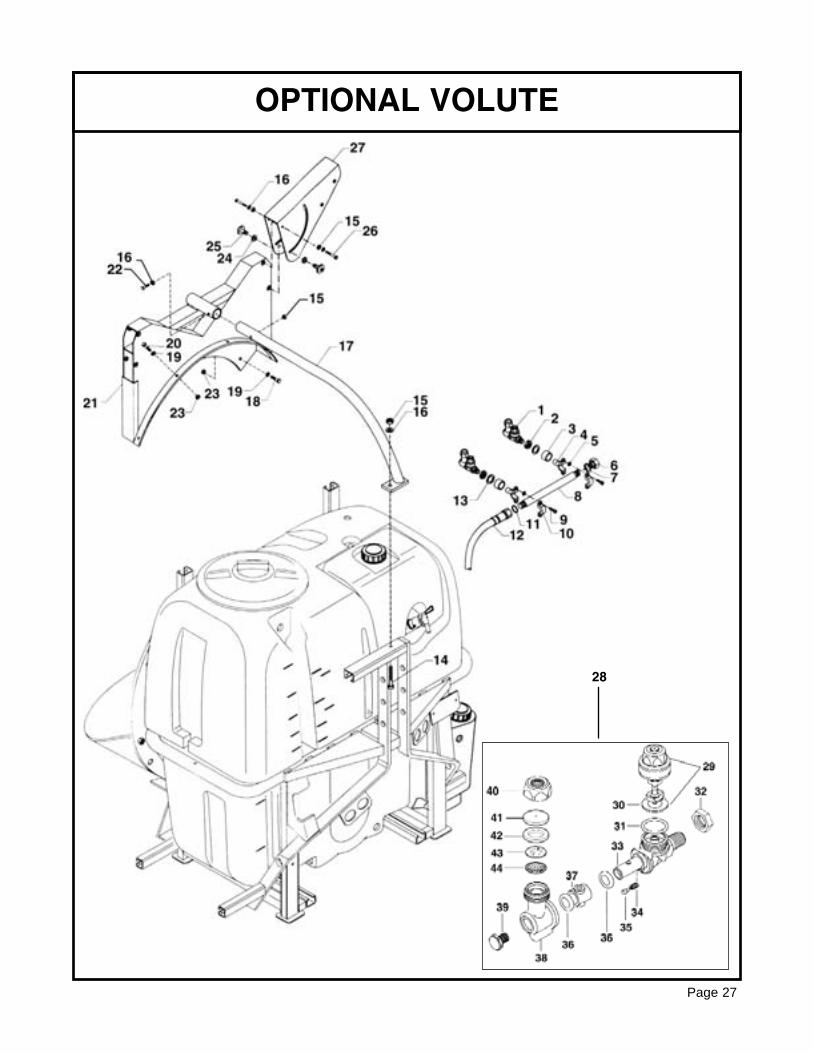
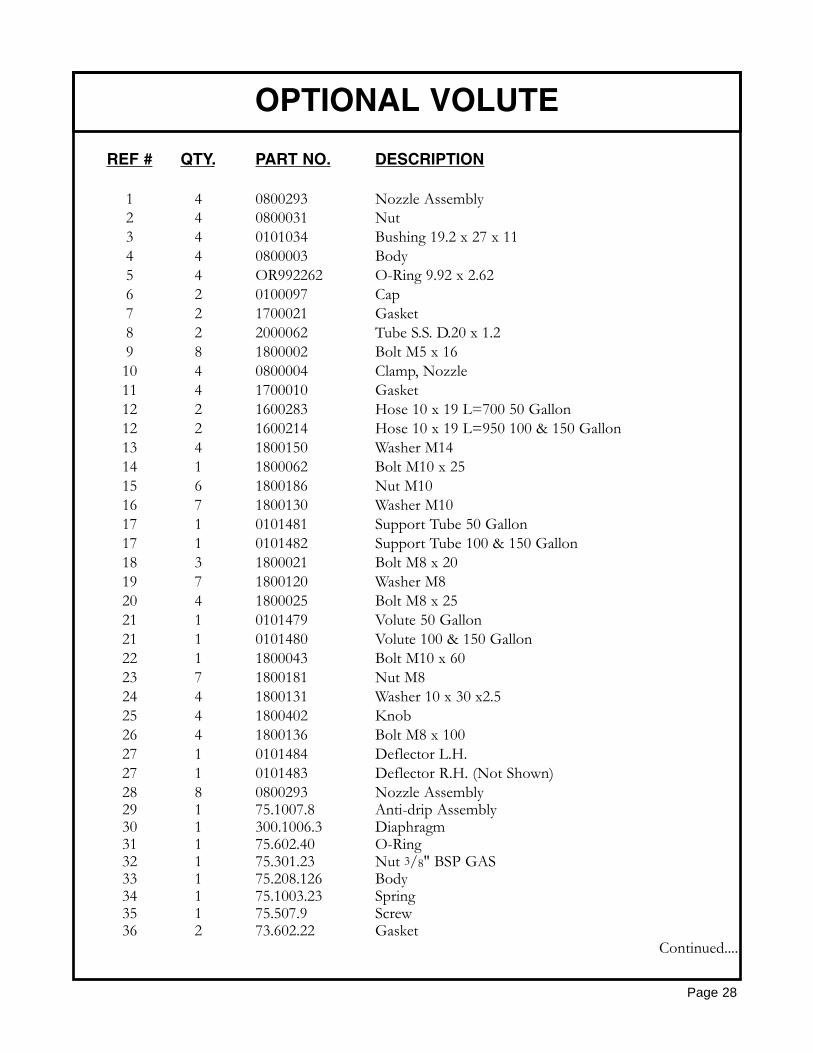
1 4 0800293 Nozzle Assembly2 4 0800031 Nut3 4 0101034 Bushing 19.2 x 27 x 114 4 0800003 Body5 4 OR992262 O-Ring 9.92 x 2.626 2 0100097 Cap7 2 1700021 Gasket8 2 2000062 Tube S.S. D.20 x 1.29 8 1800002 Bolt M5 x 1610 4 0800004 Clamp, Nozzle11 4 1700010 Gasket12 2 1600283 Hose 10 x 19 L=700 50 Gallon12 2 1600214 Hose 10 x 19 L=950 100 & 150 Gallon13 4 1800150 Washer M1414 1 1800062 Bolt M10 x 2515 6 1800186 Nut M1016 7 1800130 Washer M1017 1 0101481 Support Tube 50 Gallon17 1 0101482 Support Tube 100 & 150 Gallon18 3 1800021 Bolt M8 x 2019 7 1800120 Washer M820 4 1800025 Bolt M8 x 2521 1 0101479 Volute 50 Gallon21 1 0101480 Volute 100 & 150 Gallon22 1 1800043 Bolt M10 x 6023 7 1800181 Nut M824 4 1800131 Washer 10 x 30 x2.525 4 1800402 Knob26 4 1800136 Bolt M8 x 10027 1 0101484 Deflector L.H.27 1 0101483 Deflector R.H. (Not Shown)28 8 0800293 Nozzle Assembly29 1 75.1007.8 Anti-drip Assembly30 1 300.1006.3 Diaphragm31 1 75.602.40 O-Ring32 1 75.301.23 Nut 3/8" BSP GAS33 1 75.208.126 Body34 1 75.1003.23 Spring35 1 75.507.9 Screw36 2 73.602.22 Gasket
Continued....
OPTIONAL VOLUTE
Page 28
REF # QTY. PART NO. DESCRIPTION
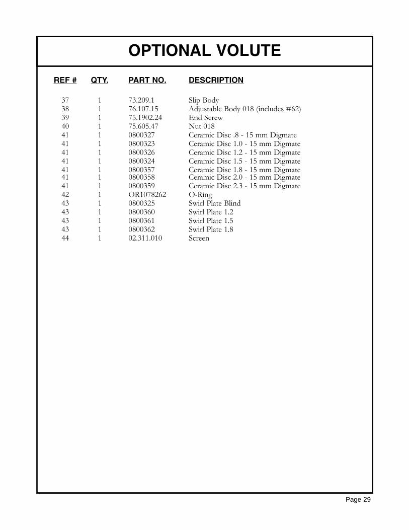
37 1 73.209.1 Slip Body38 1 76.107.15 Adjustable Body 018 (includes #62)39 1 75.1902.24 End Screw40 1 75.605.47 Nut 01841 1 0800327 Ceramic Disc .8 - 15 mm Digmate41 1 0800323 Ceramic Disc 1.0 - 15 mm Digmate41 1 0800326 Ceramic Disc 1.2 - 15 mm Digmate41 1 0800324 Ceramic Disc 1.5 - 15 mm Digmate41 1 0800357 Ceramic Disc 1.8 - 15 mm Digmate41 1 0800358 Ceramic Disc 2.0 - 15 mm Digmate41 1 0800359 Ceramic Disc 2.3 - 15 mm Digmate42 1 OR1078262 O-Ring43 1 0800325 Swirl Plate Blind43 1 0800360 Swirl Plate 1.243 1 0800361 Swirl Plate 1.543 1 0800362 Swirl Plate 1.844 1 02.311.010 Screen
OPTIONAL VOLUTE
Page 29
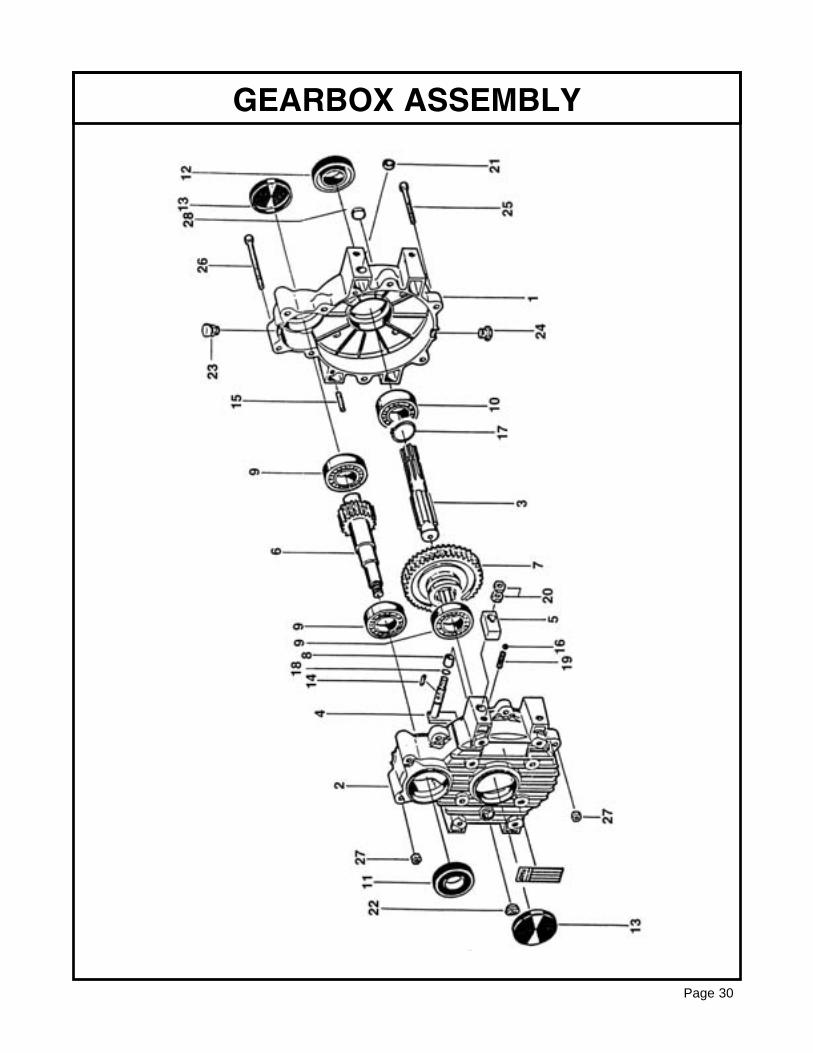
GEARBOX ASSEMBLY
Page 30
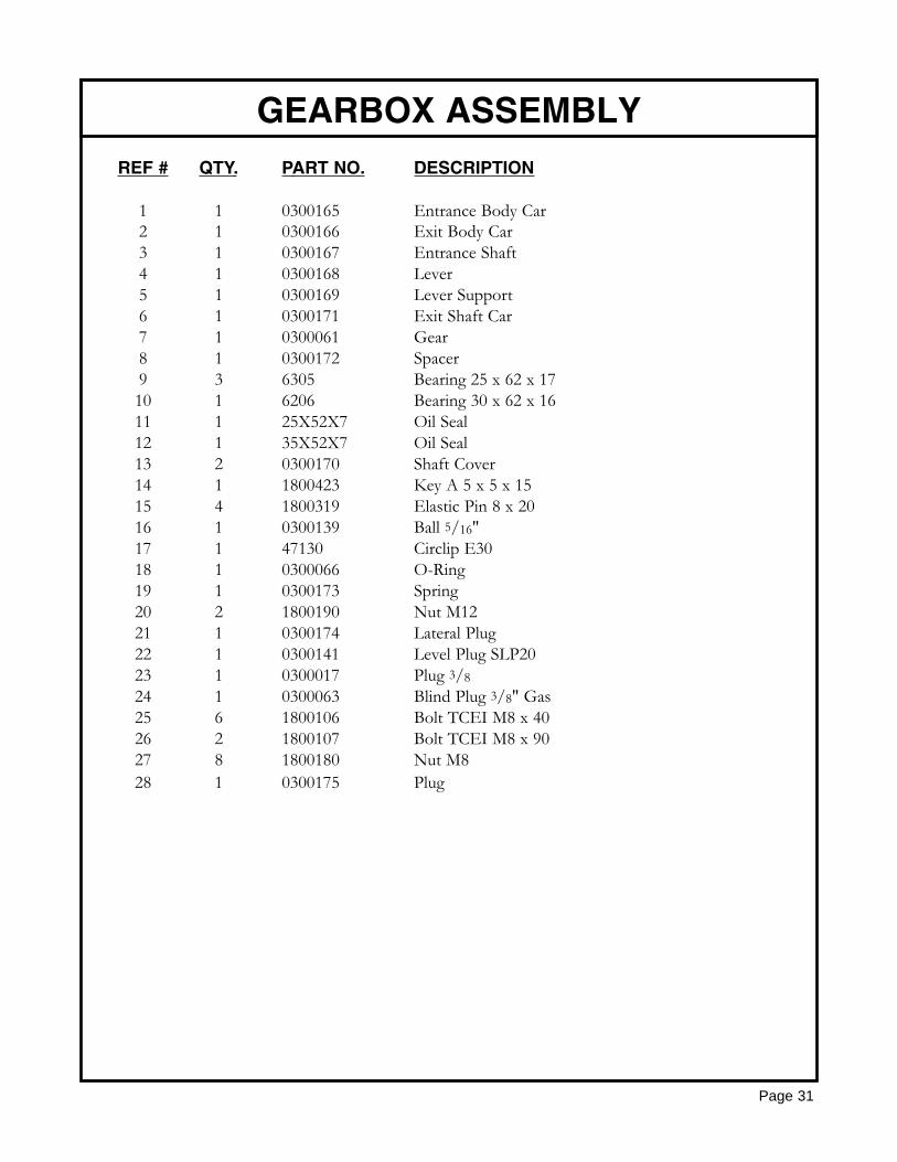
REF # QTY. PART NO. DESCRIPTION
1 1 0300165 Entrance Body Car2 1 0300166 Exit Body Car3 1 0300167 Entrance Shaft4 1 0300168 Lever5 1 0300169 Lever Support6 1 0300171 Exit Shaft Car7 1 0300061 Gear8 1 0300172 Spacer9 3 6305 Bearing 25 x 62 x 17 10 1 6206 Bearing 30 x 62 x 16 11 1 25X52X7 Oil Seal12 1 35X52X7 Oil Seal13 2 0300170 Shaft Cover14 1 1800423 Key A 5 x 5 x 1515 4 1800319 Elastic Pin 8 x 2016 1 0300139 Ball 5/16"17 1 47130 Circlip E3018 1 0300066 O-Ring19 1 0300173 Spring20 2 1800190 Nut M1221 1 0300174 Lateral Plug22 1 0300141 Level Plug SLP2023 1 0300017 Plug 3/824 1 0300063 Blind Plug 3/8" Gas25 6 1800106 Bolt TCEI M8 x 4026 2 1800107 Bolt TCEI M8 x 9027 8 1800180 Nut M828 1 0300175 Plug
GEARBOX ASSEMBLY
Page 31
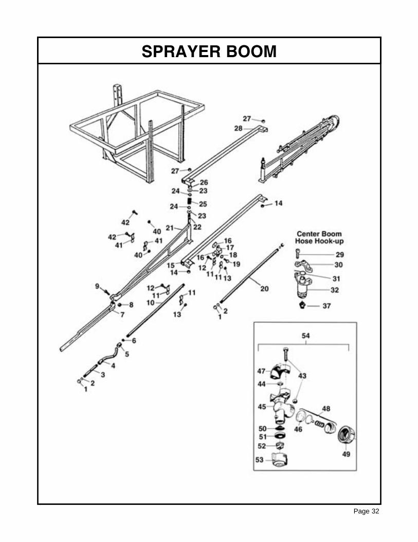
SPRAYER BOOM
Page 32
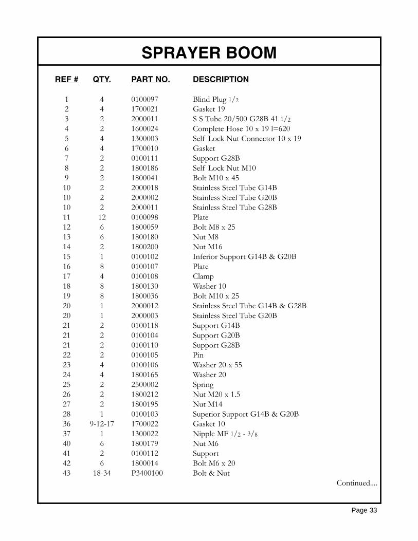
REF # QTY. PART NO. DESCRIPTION
1 4 0100097 Blind Plug 1/22 4 1700021 Gasket 193 2 2000011 S S Tube 20/500 G28B 41 1/24 2 1600024 Complete Hose 10 x 19 l=6205 4 1300003 Self Lock Nut Connector 10 x 196 4 1700010 Gasket7 2 0100111 Support G28B8 2 1800186 Self Lock Nut M109 2 1800041 Bolt M10 x 4510 2 2000018 Stainless Steel Tube G14B10 2 2000002 Stainless Steel Tube G20B10 2 2000011 Stainless Steel Tube G28B11 12 0100098 Plate12 6 1800059 Bolt M8 x 2513 6 1800180 Nut M814 2 1800200 Nut M1615 1 0100102 Inferior Support G14B & G20B16 8 0100107 Plate17 4 0100108 Clamp18 8 1800130 Washer 1019 8 1800036 Bolt M10 x 2520 1 2000012 Stainless Steel Tube G14B & G28B20 1 2000003 Stainless Steel Tube G20B21 2 0100118 Support G14B21 2 0100104 Support G20B21 2 0100110 Support G28B22 2 0100105 Pin23 4 0100106 Washer 20 x 5524 4 1800165 Washer 2025 2 2500002 Spring26 2 1800212 Nut M20 x 1.527 2 1800195 Nut M1428 1 0100103 Superior Support G14B & G20B36 9-12-17 1700022 Gasket 1037 1 1300022 Nipple MF 1/2 - 3/840 6 1800179 Nut M641 2 0100112 Support42 6 1800014 Bolt M6 x 2043 18-34 P3400100 Bolt & Nut
Continued....
SPRAYER BOOM
Page 33
REF # QTY. PART NO. DESCRIPTION
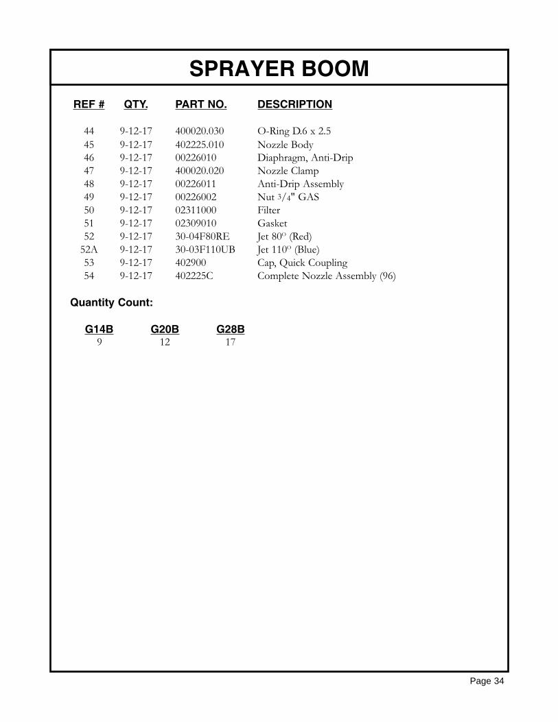
44 9-12-17 400020.030 O-Ring D.6 x 2.545 9-12-17 402225.010 Nozzle Body46 9-12-17 00226010 Diaphragm, Anti-Drip47 9-12-17 400020.020 Nozzle Clamp48 9-12-17 00226011 Anti-Drip Assembly49 9-12-17 00226002 Nut 3/4" GAS50 9-12-17 02311000 Filter51 9-12-17 02309010 Gasket52 9-12-17 30-04F80RE Jet 80O (Red)
52A 9-12-17 30-03F110UB Jet 110O (Blue)53 9-12-17 402900 Cap, Quick Coupling54 9-12-17 402225C Complete Nozzle Assembly (96)
Quantity Count:
G14B G20B G28B9 12 17
SPRAYER BOOM
Page 34
NOZZLE SPACING
Page 35
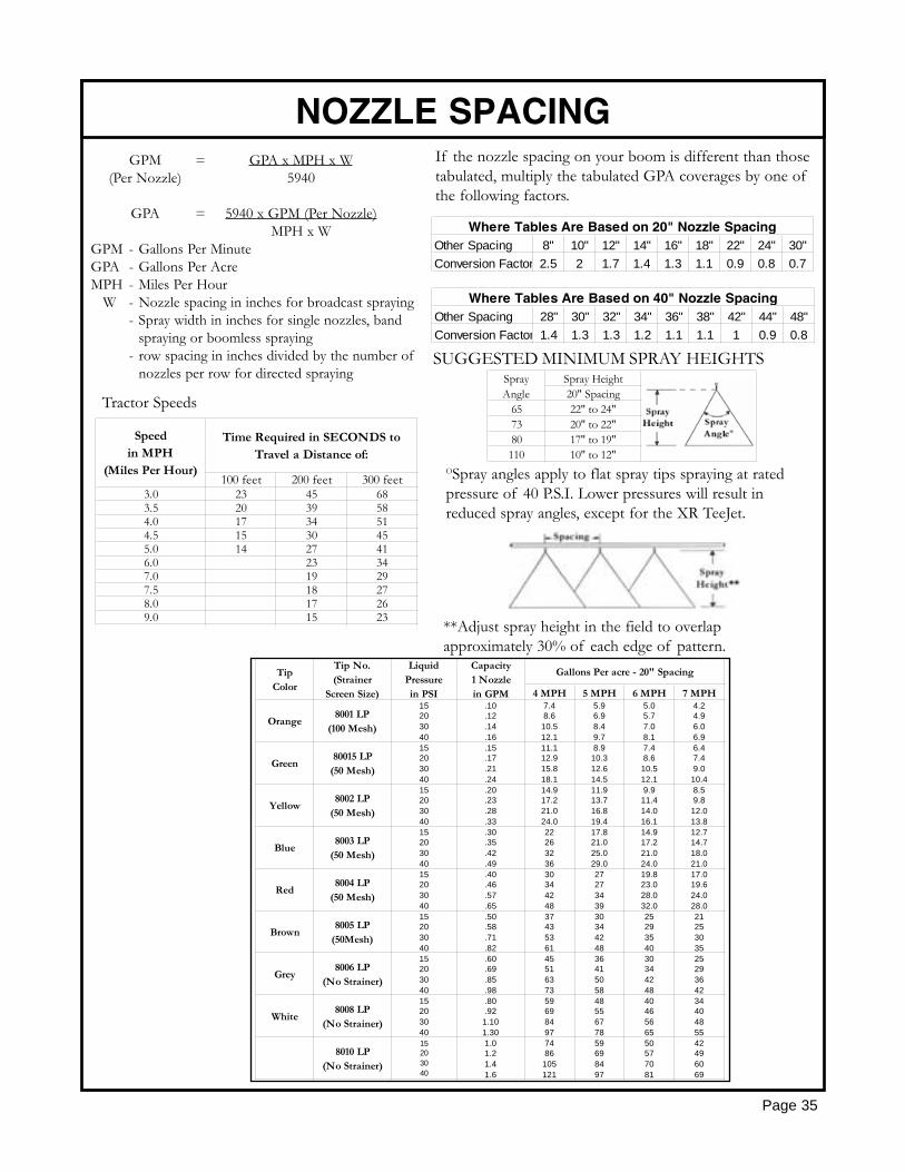
If the nozzle spacing on your boom is different than thosetabulated, multiply the tabulated GPA coverages by one ofthe following factors.
Other Spacing 8" 10" 12" 14" 16" 18" 22" 24" 30"Conversion Factor 2.5 2 1.7 1.4 1.3 1.1 0.9 0.8 0.7
Where Tables Are Based on 20" Nozzle Spacing
Other Spacing 28" 30" 32" 34" 36" 38" 42" 44" 48"Conversion Factor 1.4 1.3 1.3 1.2 1.1 1.1 1 0.9 0.8
Where Tables Are Based on 40" Nozzle Spacing
SUGGESTED MINIMUM SPRAY HEIGHTSSpray Height20" Spacing
65 22" to 24"73 20" to 22"80 17" to 19"110 10" to 12"
SprayAngle
OSpray angles apply to flat spray tips spraying at ratedpressure of 40 P.S.I. Lower pressures will result inreduced spray angles, except for the XR TeeJet.
**Adjust spray height in the field to overlap approximately 30% of each edge of pattern.
100 feet 200 feet 300 feet3.0 23 45 683.5 20 39 584.0 17 34 514.5 15 30 455.0 14 27 416.0 23 347.0 19 297.5 18 278.0 17 269.0 15 23
Speedin MPH
(Miles Per Hour)
Time Required in SECONDS toTravel a Distance of:
GPM = GPA x MPH x W(Per Nozzle) 5940
GPA = 5940 x GPM (Per Nozzle)MPH x W
GPM - Gallons Per MinuteGPA - Gallons Per AcreMPH - Miles Per Hour
W - Nozzle spacing in inches for broadcast spraying- Spray width in inches for single nozzles, band
spraying or boomless spraying- row spacing in inches divided by the number of
nozzles per row for directed spraying
Tractor Speeds
4 MPH 5 MPH 6 MPH 7 MPH
Orange8001 LP
(100 Mesh)
15203040
.10
.12
.14
.16
7.48.6
10.512.1
5.96.98.49.7
5.05.77.08.1
4.24.96.06.9
Green80015 LP
(50 Mesh)
15203040
.15
.17
.21
.24
11.112.915.818.1
8.910.312.614.5
7.48.6
10.512.1
6.47.49.0
10.4
Yellow8002 LP
(50 Mesh)
15203040
.20
.23
.28
.33
14.917.221.024.0
11.913.716.819.4
9.911.414.016.1
8.59.8
12.013.8
Blue8003 LP
(50 Mesh)
15203040
.30
.35
.42
.49
22263236
17.821.025.029.0
14.917.221.024.0
12.714.718.021.0
Red8004 LP
(50 Mesh)
15203040
.40
.46
.57
.65
30344248
27273439
19.823.028.032.0
17.019.624.028.0
Brown8005 LP
(50Mesh)
15203040
.50
.58
.71
.82
37435361
30344248
25293540
21253035
Grey8006 LP
(No Strainer)
15203040
.60
.69
.85
.98
45516373
36415058
30344248
25293642
White8008 LP
(No Strainer)
15203040
.80
.921.101.30
59698497
48556778
40465665
34404855
8010 LP(No Strainer)
15203040
1.01.21.41.6
7486
105121
59698497
50577081
42496069
Gallons Per acre - 20" SpacingTipColor
Tip No.(Strainer
Screen Size)
LiquidPressurein PSI
Capacity1 Nozzlein GPM
TOMMY GUN (GHT)
Page 36
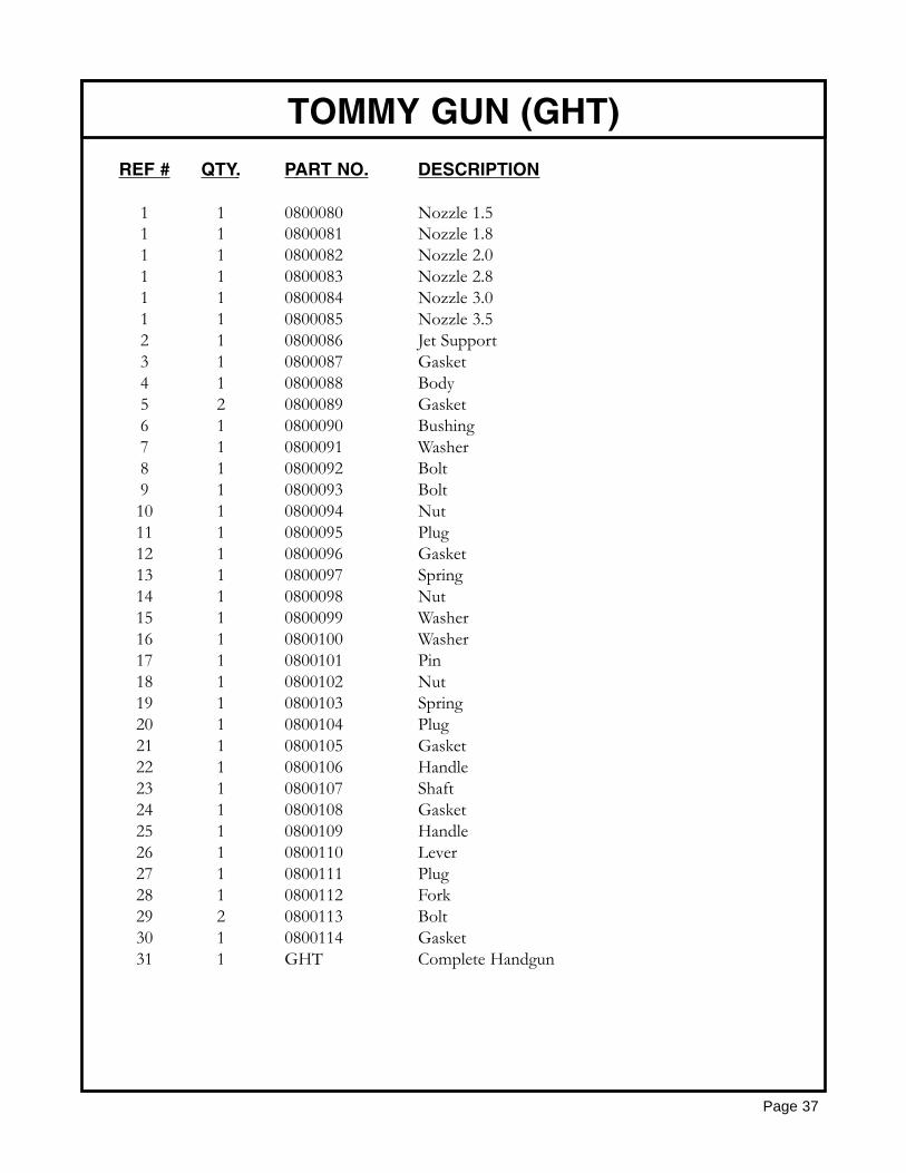
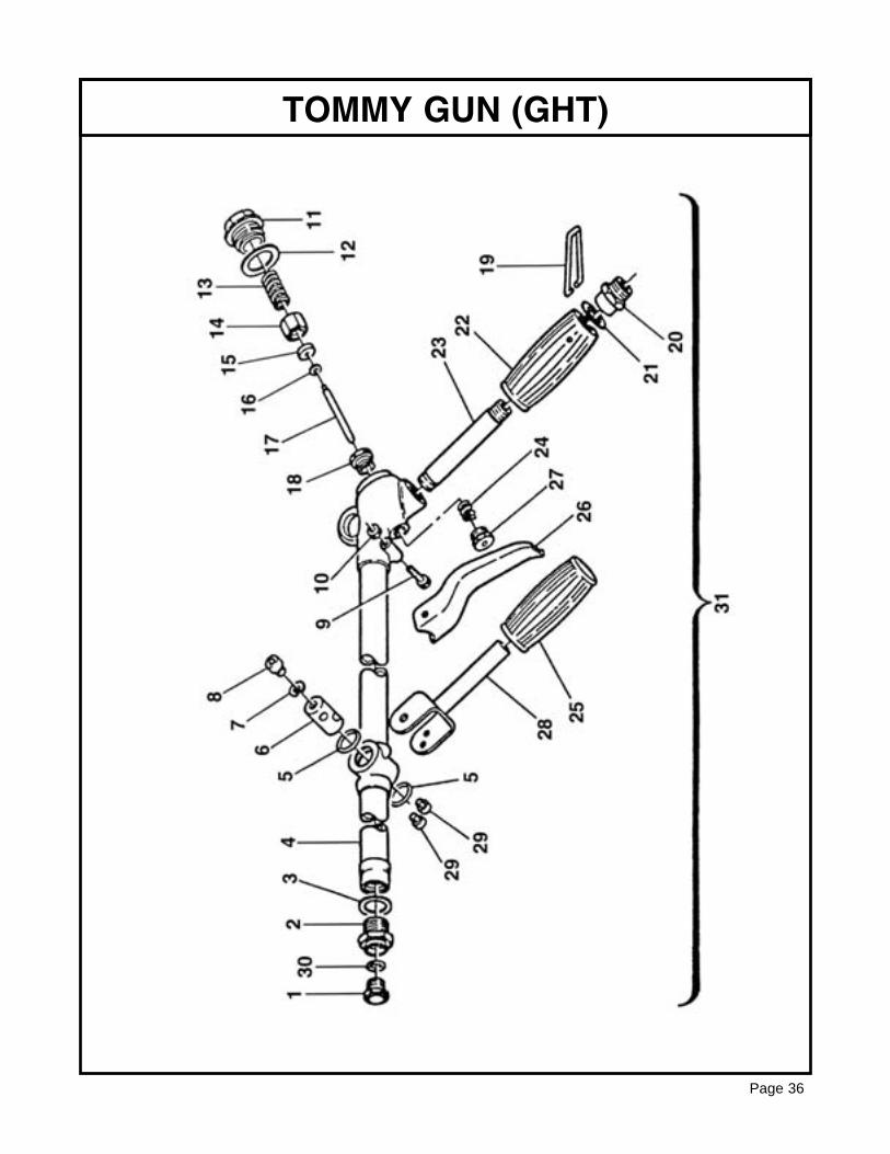
REF # QTY. PART NO. DESCRIPTION
1 1 0800080 Nozzle 1.51 1 0800081 Nozzle 1.81 1 0800082 Nozzle 2.01 1 0800083 Nozzle 2.81 1 0800084 Nozzle 3.01 1 0800085 Nozzle 3.52 1 0800086 Jet Support3 1 0800087 Gasket4 1 0800088 Body5 2 0800089 Gasket6 1 0800090 Bushing7 1 0800091 Washer8 1 0800092 Bolt9 1 0800093 Bolt10 1 0800094 Nut11 1 0800095 Plug12 1 0800096 Gasket13 1 0800097 Spring14 1 0800098 Nut15 1 0800099 Washer16 1 0800100 Washer17 1 0800101 Pin18 1 0800102 Nut19 1 0800103 Spring20 1 0800104 Plug21 1 0800105 Gasket22 1 0800106 Handle23 1 0800107 Shaft24 1 0800108 Gasket25 1 0800109 Handle26 1 0800110 Lever27 1 0800111 Plug28 1 0800112 Fork29 2 0800113 Bolt30 1 0800114 Gasket31 1 GHT Complete Handgun
TOMMY GUN (GHT)
Page 37
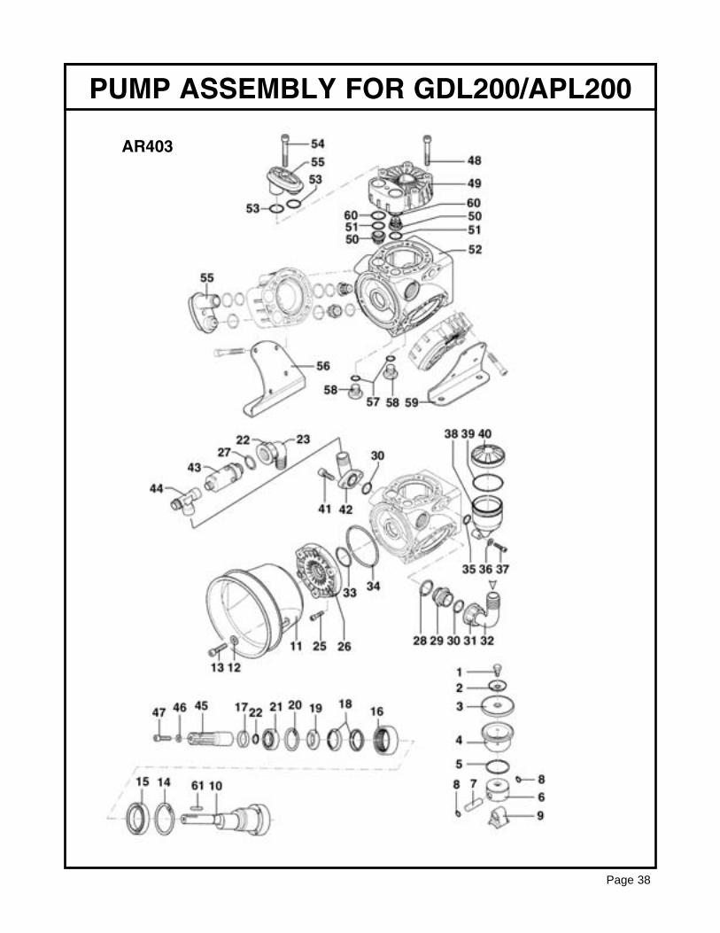
PUMP ASSEMBLY FOR GDL200/APL200
Page 38
AR403
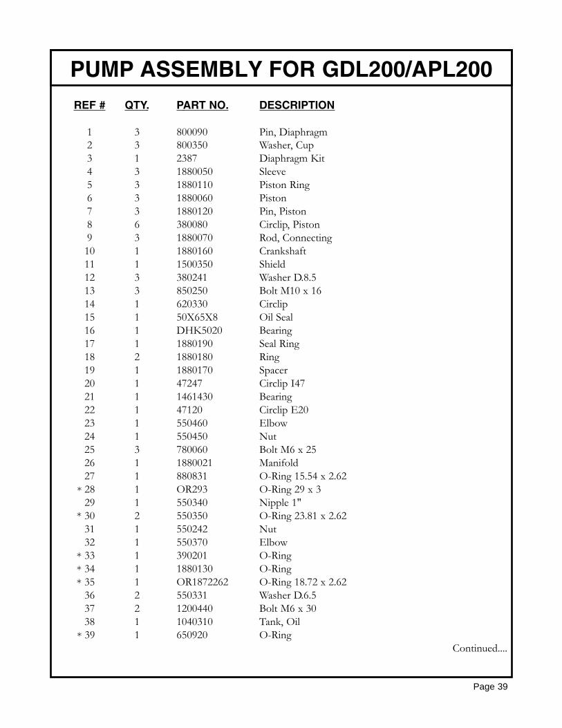
REF # QTY. PART NO. DESCRIPTION
1 3 800090 Pin, Diaphragm2 3 800350 Washer, Cup3 1 2387 Diaphragm Kit4 3 1880050 Sleeve5 3 1880110 Piston Ring6 3 1880060 Piston7 3 1880120 Pin, Piston8 6 380080 Circlip, Piston9 3 1880070 Rod, Connecting10 1 1880160 Crankshaft11 1 1500350 Shield12 3 380241 Washer D.8.513 3 850250 Bolt M10 x 1614 1 620330 Circlip15 1 50X65X8 Oil Seal16 1 DHK5020 Bearing17 1 1880190 Seal Ring18 2 1880180 Ring19 1 1880170 Spacer20 1 47247 Circlip I4721 1 1461430 Bearing22 1 47120 Circlip E2023 1 550460 Elbow24 1 550450 Nut25 3 780060 Bolt M6 x 2526 1 1880021 Manifold27 1 880831 O-Ring 15.54 x 2.6228 1 OR293 O-Ring 29 x 329 1 550340 Nipple 1"30 2 550350 O-Ring 23.81 x 2.6231 1 550242 Nut32 1 550370 Elbow33 1 390201 O-Ring34 1 1880130 O-Ring35 1 OR1872262 O-Ring 18.72 x 2.6236 2 550331 Washer D.6.537 2 1200440 Bolt M6 x 3038 1 1040310 Tank, Oil39 1 650920 O-Ring
Continued....
PUMP ASSEMBLY FOR GDL200/APL200
Page 39
*
*
***
*
REF # QTY. PART NO. DESCRIPTION
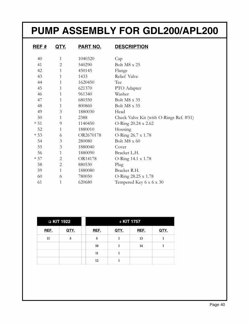
40 1 1040320 Cap41 2 540290 Bolt M8 x 2542 1 450145 Flange43 1 1433 Relief Valve44 1 1620450 Tee45 1 621370 PTO Adapter46 1 961340 Washer47 1 680350 Bolt M8 x 3548 1 800860 Bolt M8 x 5549 3 1880030 Head50 1 2388 Check Valve Kit (with O-Rings Ref. #51)51 9 1140450 O-Ring 20.24 x 2.6252 1 1880010 Housing53 6 OR2670178 O-Ring 26.7 x 1.7854 3 280080 Bolt M8 x 6055 3 1880040 Cover56 1 1880090 Bracket L.H.57 2 OR14178 O-Ring 14.1 x 1.7858 2 880530 Plug59 1 1880080 Bracket R.H.60 6 780050 O-Ring 28.25 x 1.7861 1 620680 Tempered Key 6 x 6 x 30
PUMP ASSEMBLY FOR GDL200/APL200
Page 40
*
*
*
KIT 1922 θ KIT 1757
REF. QTY. REF. QTY. REF. QTY.
11 5 5 1 13 1
10 1 14 1
11 1
12 1
REF # QTY. PART NO. DESCRIPTION
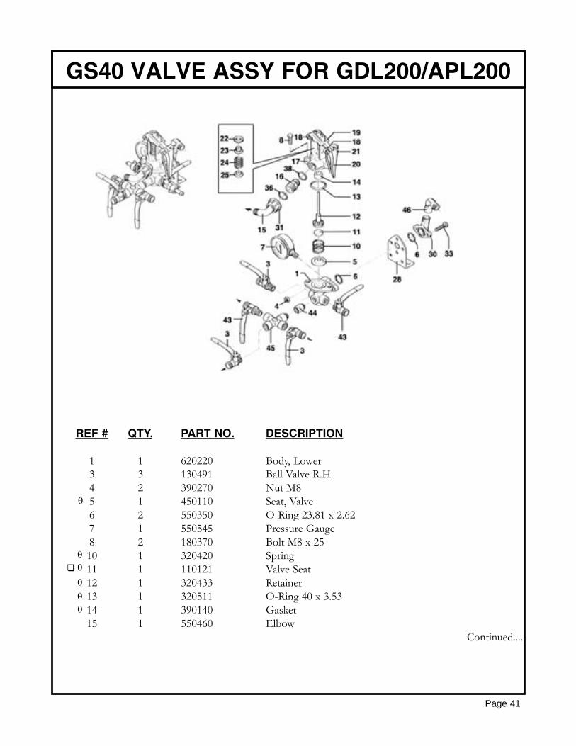
1 1 620220 Body, Lower3 3 130491 Ball Valve R.H.4 2 390270 Nut M85 1 450110 Seat, Valve6 2 550350 O-Ring 23.81 x 2.627 1 550545 Pressure Gauge8 2 180370 Bolt M8 x 2510 1 320420 Spring11 1 110121 Valve Seat12 1 320433 Retainer13 1 320511 O-Ring 40 x 3.5314 1 390140 Gasket15 1 550460 Elbow
Continued....
GS40 VALVE ASSY FOR GDL200/APL200
Page 41
θ
θθθθθ
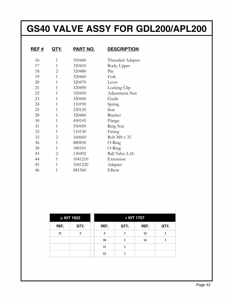
REF # QTY. PART NO. DESCRIPTION
16 1 550440 Threaded Adapter17 1 320410 Body, Upper18 2 320480 Pin19 1 320460 Fork20 1 320470 Lever21 1 320490 Locking Clip22 1 320450 Adjustment Nut23 1 320440 Guide24 1 110190 Spring25 1 230120 Seat28 1 320406 Bracket30 1 450145 Flange31 1 550450 Ring Nut32 1 110130 Fitting33 2 160660 Bolt M8 x 3536 1 880830 O-Ring38 1 180101 O-Ring43 2 130492 Ball Valve L.H.44 1 1041210 Extension45 1 1041220 Adapter46 1 881560 Elbow
GS40 VALVE ASSY FOR GDL200/APL200
Page 42
KIT 1922 θ KIT 1757
REF. QTY. REF. QTY. REF. QTY.
11 5 5 1 13 1
10 1 14 1
11 1
12 1
PUMP ASSY GDL400 & 600/APL400 & 600
Page 43
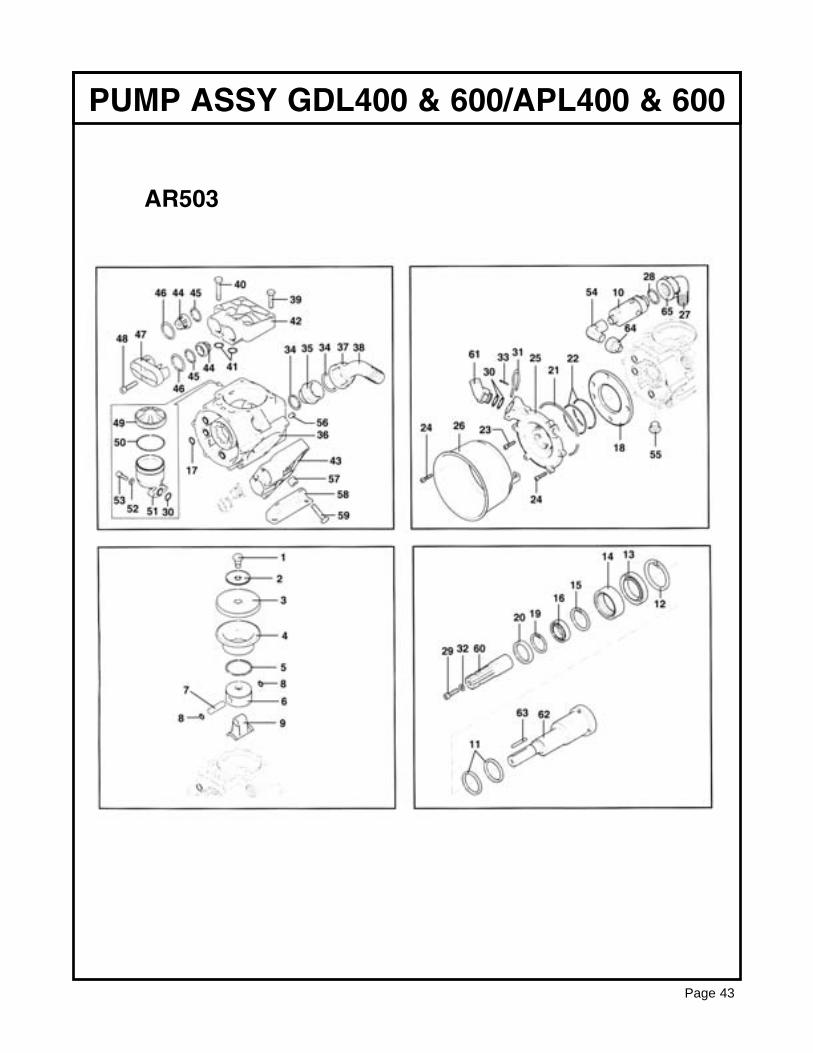
AR503
REF # QTY. PART NO. DESCRIPTION
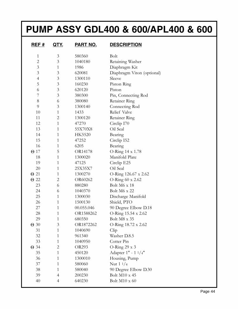
1 3 580360 Bolt2 3 1040180 Retaining Washer3 1 1986 Diaphragm Kit3 3 620081 Diaphragm Viton (optional)4 3 1300110 Sleeve5 3 160230 Piston Ring6 3 620120 Piston7 3 380300 Pin, Connecting Rod8 6 380080 Retainer Ring9 3 1300140 Connecting Rod10 1 1433 Relief Valve11 2 1300120 Retainer Ring12 1 47270 Circlip I7013 1 55X70X8 Oil Seal14 1 HK5520 Bearing15 1 47252 Circlip I5216 1 6205 Bearing17 5 OR14178 O-Ring 14 x 1.7818 1 1300020 Manifold Plate19 1 47125 Circlip E2520 1 25X35X7 Oil Seal21 1 1300270 O-Ring 126.67 x 2.6222 2 OR60262 O-Ring 60 x 2.6223 6 880280 Bolt M6 x 1824 6 1040370 Bolt M6 x 2225 1 1300030 Discharge Manifold26 1 1500130 Shield, PTO27 1 00.055.046 90 Degree Elbow D.1828 1 OR1588262 O-Ring 15.54 x 2.6229 1 680350 Bolt M8 x 3530 3 OR1872262 O-Ring 18.72 x 2.6231 1 1040690 Clip32 1 961340 Washer D.8.533 1 1040950 Cotter Pin34 2 OR293 O-Ring 29 x 335 1 450120 Adapter 1" - 1 1/4"36 1 1300010 Housing, Pump37 1 580060 Nut 1 1/438 1 580040 90 Degree Elbow D.3039 4 200230 Bolt M10 x 4540 4 640230 Bolt M10 x 60
PUMP ASSY GDL400 & 600/APL400 & 600
Page 44
Θ
ΘΘ
Θ
Θ
REF # QTY. PART NO. DESCRIPTION
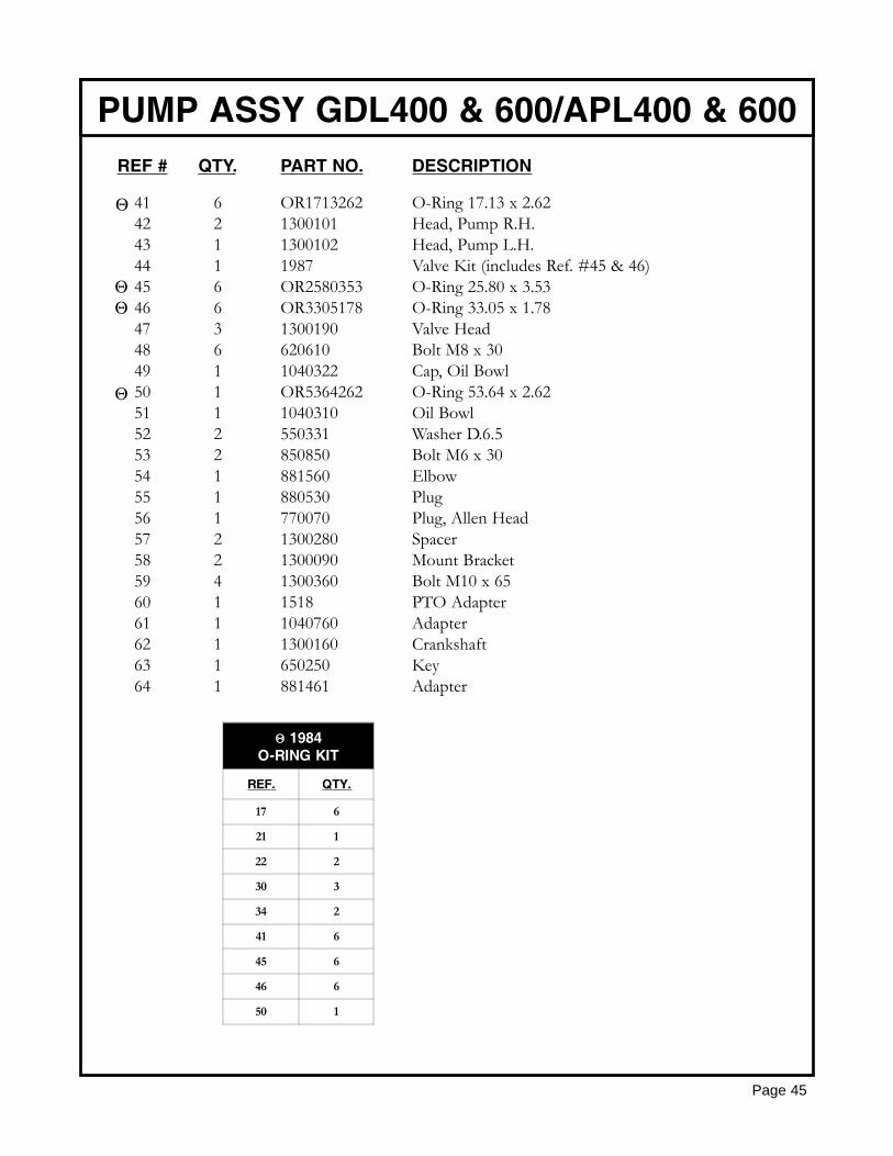
41 6 OR1713262 O-Ring 17.13 x 2.6242 2 1300101 Head, Pump R.H.43 1 1300102 Head, Pump L.H.44 1 1987 Valve Kit (includes Ref. #45 & 46)45 6 OR2580353 O-Ring 25.80 x 3.5346 6 OR3305178 O-Ring 33.05 x 1.7847 3 1300190 Valve Head48 6 620610 Bolt M8 x 3049 1 1040322 Cap, Oil Bowl50 1 OR5364262 O-Ring 53.64 x 2.6251 1 1040310 Oil Bowl52 2 550331 Washer D.6.553 2 850850 Bolt M6 x 3054 1 881560 Elbow55 1 880530 Plug56 1 770070 Plug, Allen Head57 2 1300280 Spacer58 2 1300090 Mount Bracket59 4 1300360 Bolt M10 x 6560 1 1518 PTO Adapter61 1 1040760 Adapter62 1 1300160 Crankshaft63 1 650250 Key64 1 881461 Adapter
PUMP ASSY GDL400 & 600/APL400 & 600
Page 45
Θ
ΘΘ
Θ
Θ 1984O-RING KIT
REF. QTY.
17 6
21 1
22 2
30 3
34 2
41 6
45 6
46 6
50 1
REF # QTY. PART NO. DESCRIPTION
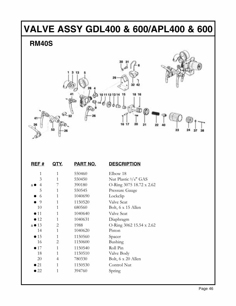
1 1 550460 Elbow 183 1 550450 Nut Plastic 3/4" GAS
∆ 4 7 390180 O-Ring 3075 18.72 x 2.625 1 550545 Pressure Gauge6 1 1040690 Lockclip9 1 1150520 Valve Seat
10 1 680560 Bolt, 6 x 15 Allen11 1 1040640 Valve Seat12 1 1040631 Diaphragm
∆ 13 2 1988 O-Ring 3062 15.54 x 2.6214 1 1040620 Piston15 1 1150560 Spacer16 2 1150600 Bushing17 1 1150540 Roll Pin18 1 1150510 Valve Body20 4 780330 Bolt, 6 x 20 Allen21 1 1150530 Control Nut22 1 394760 Spring
VALVE ASSY GDL400 & 600/APL400 & 600
Page 46
RM40S
REF # QTY. PART NO. DESCRIPTION
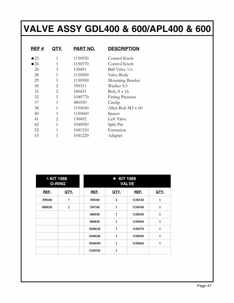
23 1 1150550 Control Knob24 1 1150570 Control Knob26 3 130491 Ball Valve 3/828 1 1150500 Valve Body29 1 1150590 Mounting Bracket30 2 390311 Washer 8.531 2 180431 Bolt, 8 x 1632 1 1040770 Fitting Pressure37 1 480550 Circlip38 1 1150650 Allen Bolt M3 x 6040 1 1150660 Spacer41 2 130492 Left Valve42 1 1040950 Split Pin52 1 1041210 Extension53 1 1041220 Adapter
VALVE ASSY GDL400 & 600/APL400 & 600
Page 47
KIT 1988O-RING
KIT 1989VALVE
REF. QTY. REF. QTY. REF. QTY.
390180 7 390180 4 1150530 1
880830 2 394760 1 1150540 1
480550 1 1150550 1
880830 1 1150560 1
1040630 1 1150570 1
1040640 1 1150650 1
1040690 1 1150660 1
1150520 1
∆
HOSE REEL 112-4-75
Page 48
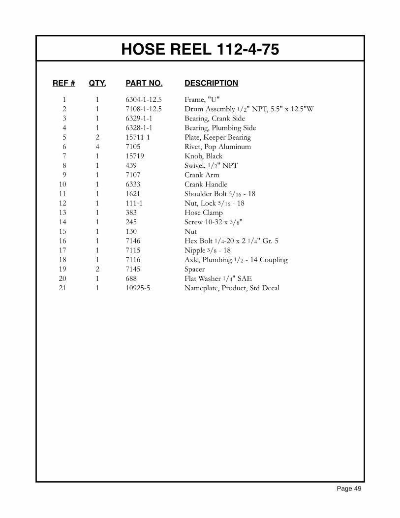
REF # QTY. PART NO. DESCRIPTION
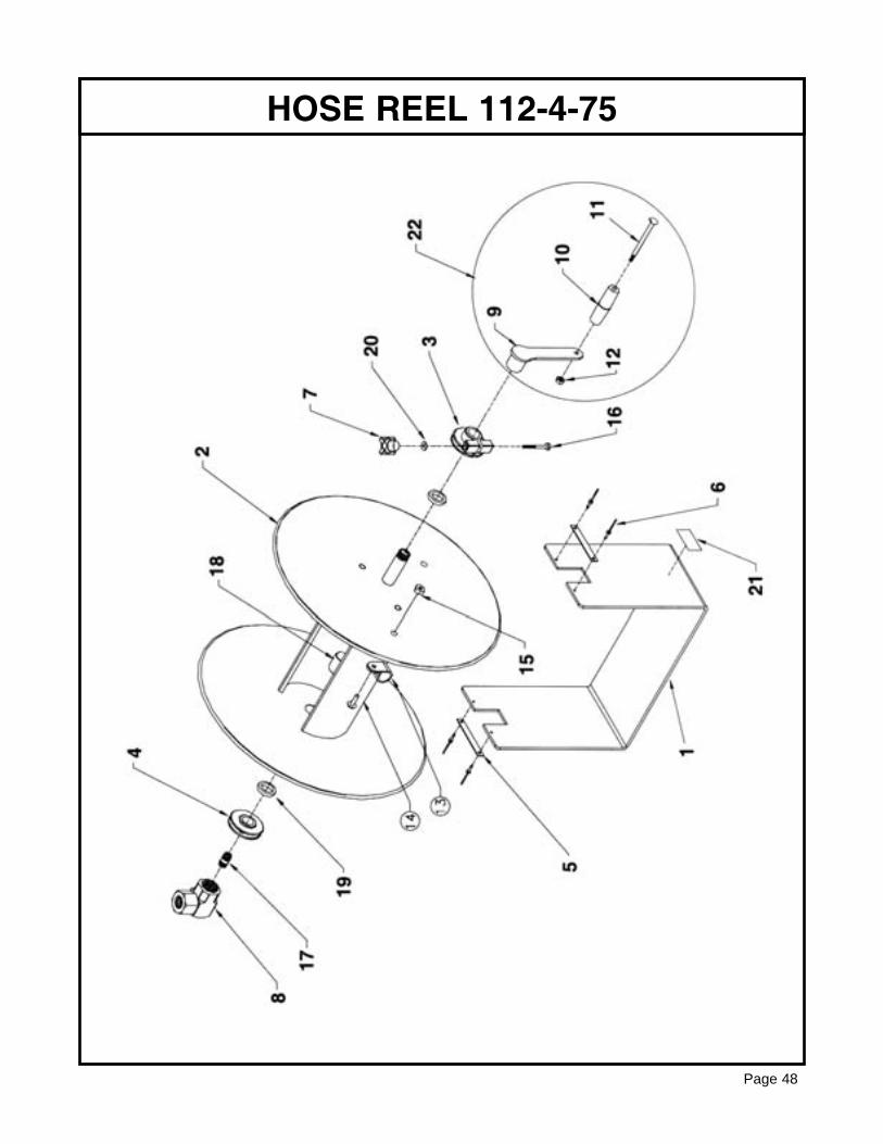
1 1 6304-1-12.5 Frame, "U"2 1 7108-1-12.5 Drum Assembly 1/2" NPT, 5.5" x 12.5"W3 1 6329-1-1 Bearing, Crank Side4 1 6328-1-1 Bearing, Plumbing Side5 2 15711-1 Plate, Keeper Bearing6 4 7105 Rivet, Pop Aluminum7 1 15719 Knob, Black8 1 439 Swivel, 1/2" NPT9 1 7107 Crank Arm
10 1 6333 Crank Handle11 1 1621 Shoulder Bolt 5/16 - 1812 1 111-1 Nut, Lock 5/16 - 1813 1 383 Hose Clamp14 1 245 Screw 10-32 x 3/8"15 1 130 Nut16 1 7146 Hex Bolt 1/4-20 x 2 1/4" Gr. 517 1 7115 Nipple 3/8 - 1818 1 7116 Axle, Plumbing 1/2 - 14 Coupling19 2 7145 Spacer20 1 688 Flat Washer 1/4" SAE21 1 10925-5 Nameplate, Product, Std Decal
HOSE REEL 112-4-75
Page 49
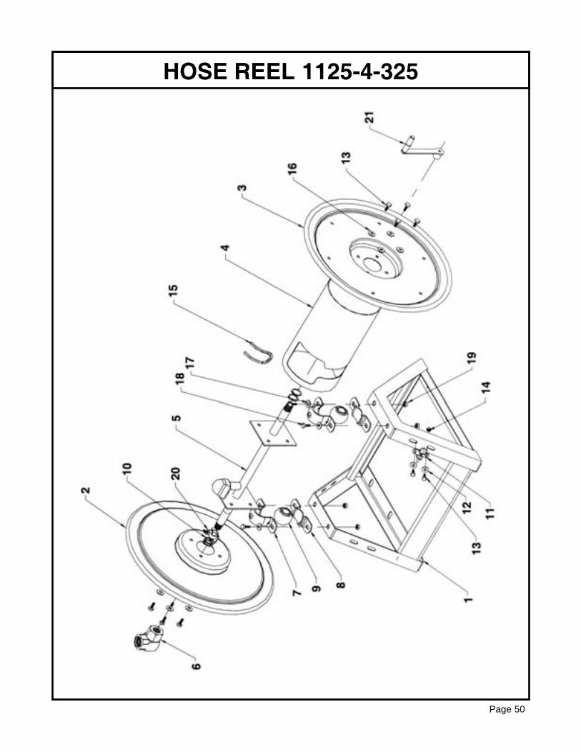
HOSE REEL 1125-4-325
Page 50
REF # QTY. PART NO. DESCRIPTION
1 1 7455-18 Frame2 1 7415 Disc, Swivel Side3 1 7416 Disc, Crank Side4 1 7414-18 Center Drum5 1 7408-18 Axle Assembly6 1 439 Swivel7 2 20064-T Pillow Block, Mtg, Top8 2 20064-B Pillow Block, Mtg, Bottom9 2 20649 Bearing
10 4 153 Ring11 1 20843 Lock Pin Assembly12 2 20171 Flat Washer 5/16"13 10 312 Bolt 5/16 - 18 x 3/4" Lg14 2 111 Locking Nut 5/16"15 1 7460-9.75 Trim16 8 112 Lock Washer 5/16"17 4 157 Flat Washer 3/8"18 4 20016 Bolt 3/8 x 16 x 1" Lg19 4 435 Locking Nut 3/8"20 1 7429-4 Drag Brake21 1 7419-1 Hand Crank
HOSE REEL 1125-4-325
Page 51
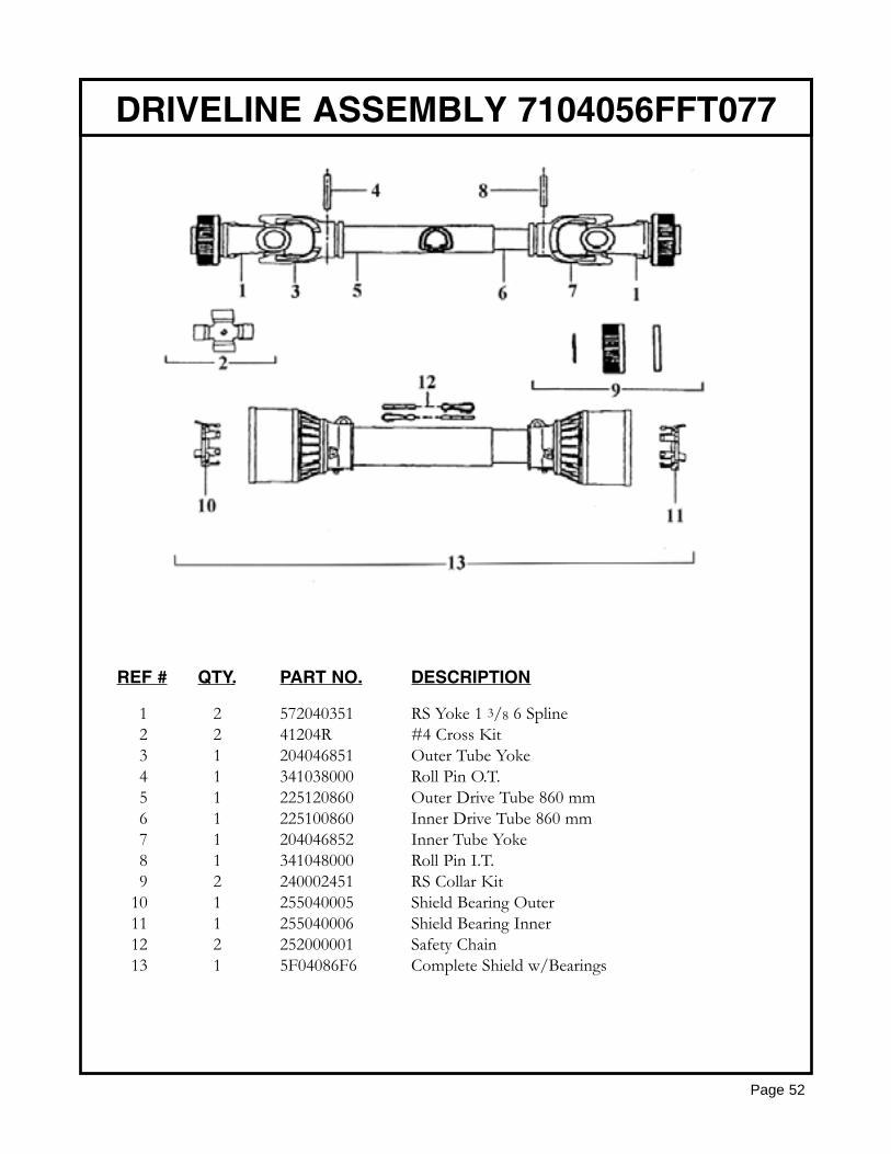
REF # QTY. PART NO. DESCRIPTION
1 2 572040351 RS Yoke 1 3/8 6 Spline2 2 41204R #4 Cross Kit3 1 204046851 Outer Tube Yoke4 1 341038000 Roll Pin O.T.5 1 225120860 Outer Drive Tube 860 mm6 1 225100860 Inner Drive Tube 860 mm7 1 204046852 Inner Tube Yoke8 1 341048000 Roll Pin I.T.9 2 240002451 RS Collar Kit
10 1 255040005 Shield Bearing Outer11 1 255040006 Shield Bearing Inner12 2 252000001 Safety Chain13 1 5F04086F6 Complete Shield w/Bearings
DRIVELINE ASSEMBLY 7104056FFT077
Page 52
Page 53
GEARMORE, INC., warrants each new Gearmore product to be free from defects in materi-al and workmanship for a period of twelve (12) months from date of purchase to the originalpurchaser. This warranty shall not apply to implements or parts that have been subject tomisuse, negligence, accident, or that have been altered in any way.
Our obligation shall be limited to repairing or replacement of any part, provided that suchpart is returned within thirty (30) days from date of failure to Gearmore through the dealerfrom whom the purchase was made, transportation charges prepaid.
This warranty shall not be interpreted to render us liable for injury or damages of any kind ornature, direct, consequential or contingent, to person or property. This warranty does notextend to loss of crops, loss because of delay in harvesting or any other expenses, for anyother reasons.
Gearmore in no way warranties engines, tires, or other trade accessories, since these itemsare warranted separately by these respective manufacturers.
Gearmore reserves the right to make improvements in design or changes in specification atany time, without incurring any obligations to owners or units previously sold.
GEARMORE, INC.13740 Magnolia Ave.
Chino, CA 91710Always refer to and heed machine operating warning decals on machine.
LIMITED WARRANTY
The serial number of this product is stored in our computer database, thussubmitting a warranty registration card is not required.