Embed Size (px)
Citation preview

....... \ " Form 3160-3
(March 2012) OCD Artesia
HIGH CAVEKARST UNITED STATES
DEPARTMENT OF THE INTERIOR BUREAU OF LAND MANAGEMENT
APPLICATION FOR PERMIT TO DRILL OR REENTER
FORM APPROVED OMB No. 1004-0137
Expires October31,2014
5. Lease Serial No. NM-107383
6. If Indian, Allotee or Tribe Name
la. Type of work: [7] DRILL \ ~ } REENTER
lb. Type of Well: [7] Oil Well Q Gas Well f j ] Other [71 Single Zone | ~ | Multiple Zone
7 If Unit or C A Agreement, Name and No.
8. Lease Name and Well No. Marcell BMM Federal #2H
2. Name of Operator YATES PETROLEUM CORPORATION 9. API Well No. 30-015-
<31553}
3a. Address -|fj5 South Fourth Street Artesia, NM 88220 3b. Phone No. (include area code) 575-748-4347
4. Location of Well (Report location clearly and in accordance with any State requirements. *)
At surface 2310' FNL and 150' FWL
At proposed prod, zone 1650' FNL and 330' FWL
10. Field and Pool, or Exploratory
UncTesii Tgriated Wolfcamp eft
14. Distance in miles and direction from nearest town or post office* Approximately 12 miles north of Loco Hills, New Mexico.
15. Distance from proposed* location to nearest property or lease line, ft. (Also to nearest drig. unit line, if any)
150'
18. Distance from proposed location* to nearest well, drilling, completed, applied for, on this lease, ft.
Approximately 1300'
21. Elevations (Show whether DF, KDB, RT, GL, etc.) 3798' GL
16. No. of acres in lease 327.28
19. Proposed Depth 7290'TVD 12227'TMD
11. Sec, T. R. M. or Blk. and Survey or Area
Section 6, T16S-R30E
12. County or Parish Eddy County
13. State NM
17. Spacing Unit dedicated to this well S/2N/2
20. BLM/BIA Bond No. on file Nationwide Bond: NMB-000434 Individual Bond: NMB-000920
22 Approximate date work will start* 07/01/2013
23. Estimated duration 45 Days
24. Attachments
The following, completed in accordance with the requirements of Onshore Oil and Gas Order No.1, must be attached tD this form:
1. Well plat certified by a registered surveyor. 2. A Drilling Plan. 3. A Surface Use Plan (if the location is on National Forest System Lands, the
SUPO must be filedw^tl^pprojipateTj'est Service Office).
4. Bond to. cover the operations unless covered by an existing bond on file (see Item 20 above).
5. Operator certification 6. Such other site specific information and/or plans as may be required by the
BLM.
25. Signature / ( ^T"V. J\ Name (Printed/Typed) Cy Cowan. ̂
Date 03/12/2013
Title /
Approved by ^ g ^ p ^ j _ Q A F F E Y Name (Printed/Typed) 1 2 2013
Title FIELD MANAGER
Office CARLSBAD FIELD OFFICE
Application approval does not warrant or certify that the applicant holds legal or equitable title to those rights in the subject lease which would entitle the applicant to
Conditions of approval, if any, are attached. APPROVAL FOR TWO YEARS Title 18 U.S.C. Section 1001 and Title 43 U.S.C. Section 1212, make it a crime for any person knowingly and willfully to make to any department or agency of the United States any false, fictitious or fraudulent statements or representations as to any matter within its jurisdiction.
(Continued on page 2)
Roswell Controlled Water Basin
"(Instructions on page 2)
SEP J 7 2013
SEE ATTACHED FOR CONDITIONS OF APPROVAL
Approval Subject to General Requirements & Special Stipulations Attached

>
CERTIFICATION YATES PETROLEUM CORPORATION
Marcell BMM Federal #2H
I hereby certify that I , or someone under my direct supervision, have inspected the drill site and access route proposed herein; that I am familiar with the conditions which currently exist; and an someone under employment of Yates Petroleum Corporation has full knowledge of state and federal laws applicable to this operation; that the statements made in this APD package are, to the best of my knowledge, true and correct; and that the work associated with the operations proposed herein will be performed in conformity with this APD package and the terms and conditions under which it is approved. I also certify that I , or the company I represent, am responsible for the operations conducted under this application. These statements are subject to the provisions of 18 U.S.C. 1001 for the filing of false statements.
Executed this
Signature
2013
Name Cy Cowan'
Position Title Land Regulatory Agent
Address 105 South Fourth Street, Artesia, New Mexico 88210
Telephone (505) 748-4372
Field Representative (if not above signatory) Tim Bussell, Drilling Supervisor
Address (if different from above) Same as above.
Telephone (if different from above) (505) 748-4221
E-mail (optional)
» V
DISTRICT I 1625 N. French Dr., Hobbs, Ni l 88240
DISTRICT I I 1301 W. Grand Avenue, Artesia, NU 88210
DISTRICT III 1000 Bio Brazos Rd., Aztec, NM 87410
DISTRICT IV 1220 S. St. Francis Dr., Santa Fe, NM 87505
Sta te o f New M e x i c o E n e r g y , M i n e r a l s a n d N a t u r a l Resources D e p a r t m e n t
OIL CONSERVATION DIVISION 1220 South St. Francis Dr.
Santa Fe, New Mexico 87505
Form C-102 Revised October 12, 2005
S u b m i t to Appropr ia te D i s t r i c t Off ice
State Lease - 4 Copies
Fee Lease — 3 Copies
• AMENDED REPORT WELL LOCATION AND ACREAGE DEDICATION PLAT
API Number
30-0,5-MUo3'l Pool Code
99/97 Pool Name
Undcsignn-t-ori Wnf rump £ o . / _ j p J i p TANK* Ako Property Code Property Name
MARCEL "BMM" FEDERAL Well Number
2H OGRID No.
025575 Operator Name
YATES PETROLEUM CORP. Elevation
3798'
Surface Location
UL or lo t No.
LOT 5
Section
6 Township
16 S Range
30 E Lot Idn Feet f r o m the
,/ 2310 North/South line
NORTH Feet f r o m the
150 East/West line
WEST County
EDDY
Bottom Hole Location If Different From Surface UL or lo t No.
LOT 5
Section
1 Township
16 S Range
29 E Lot Idn Feet f r o m the
1650 North/South line
NORTH Feet f r o m the
330 East/West line
WEST County
EDDY Dedicated Acres
160
Joint or I n f i l l Consolidation Code Order No.
NO ALLOWABLE WILL BE ASSIGNED TO THIS COMPLETION UNTIL ALL INTERESTS HAVE BEEN CONSOLIDATED OR A NON-STANDARD UNIT HAS BEEN APPROVED BY THE DIVISION
BOTTOM HOLE LOCATION Lat - N32'57"39.01" Long - W104*02*08.69"
N.: 713417.119 E.: 632611.025 (NAD-83)
SPC-^
SURFACE LOCATION Lat - N32*57'32.32" Long - W104*0r08.88"
N.: 712755.598 E.: 637708.888 (NAD-83)
SPC
B.H.
Project A
Producin,
si4o.er
Zone
•- -1" 3792.3 3802.3'
ll50' 3793.11
entetrat ibn Point 2247' FNL|i 333 ' FEL
I
3801.8
I
SCALE - 1 = 2000
OPERATOR CERTIFICATION
/ hereby certify that the information contained herein is true and complete to the best of my knowledge and belief, and that this organization either owns a working interest or unleased mineral interest in the land including the proposed bottom hole location pursuant to a contract with an owner of such a mineral or working interest, or to a voluntary pooling agreement or a compulsory pooling^order heretofore entered by the div'
P r i n t e d N a m e
SURVEYOR CERTIFICATION
/ hereby certify that the well location shown
on this plat was plotted from field notes of
actual surveys made by me or under my
supervisor and that the same is true and
correct to the best of my belief.
Certificate No. Gary L Jones 7977
BASIN SURVEYS
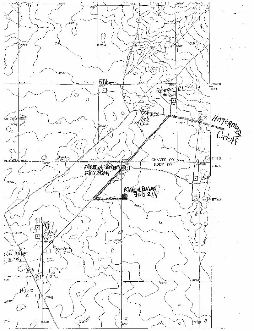
SECTION 1, TOWNSHIP 16 SOUTH, RANGE 30 EAST, N.M.P.M., EDDY COUNTY, NEW MEXICO.
i f
A'
0<y/
PROPOSED LEASE ROAD 1881.7'
379Z3' 600' 3802.3'
150' NORTH OFF SET 3797.3'
D
YATES PETROLEUM CORP. MARCEL "BUM" FEDERAL #ZH
Eler. - 3798' 150' WEST 150' EAST OFF SET d O d OFF SET 3794.9' Lat.: H 32-57'32.32" 3800.8'
Long.: W 104'0r08.88"
SPC-
3793.1'
N.: 712755.598 E.: 637708.888
(NAD-83)
a 750' SOUTH
OFF SET 3797.3'
600' 3801.8'
100 0 100 ZOO FEET L_| M M M M | | |
SCALE: 1 " = 100'
B iS iSM S X J E V B Y S P.O. BOX 1786—HOBBS, NEW MEXICO
YATES PETROLEUM CORP.
BiSiSM S X J E V B Y S P.O. BOX 1786—HOBBS, NEW MEXICO
REF: MARCEL "BMM" FEDERAL #2H / WELL PAD TOPO
BiS iSM S X J E V B Y S P.O. BOX 1786—HOBBS, NEW MEXICO
THE MARCEL "BMM" FEDERAL #2H LOCATED 2310'
FROM THE NORTH LINE AND 150' FROM THE WEST LINE OF
SECTION 6, TOWNSHIP 16 SOUTH, RANGE 30 EAST,
N.M.P.M., EDDY COUNTY. NEW MEXICO. W.O. Number: 20721 Drawn By: J. M. SMALL
THE MARCEL "BMM" FEDERAL #2H LOCATED 2310'
FROM THE NORTH LINE AND 150' FROM THE WEST LINE OF
SECTION 6, TOWNSHIP 16 SOUTH, RANGE 30 EAST,
N.M.P.M., EDDY COUNTY. NEW MEXICO.
Date: 10-25-2008 I Disk- 20721 JMS Survey Date: 10-24-2008 I Sheet 1 of 1 Sheets

I I 1
'Sutimor0 U.S. I2i
SuJimar
* ' HBC 5/2
( M l
to
/ s; *.»#
PI
" .V / / 5 / ~ -
SHOO
\ ° a o a 0 o i
Ytri* s Per. etoj.
SS 3
mi'**..
\
A 051 £ 12 Gen Affter, -J Forrnvr §
M ^ * * • D ^ - - - # i
® 1 CO) W ro+r5 Per " *
Be l lwe f her
0 "# * * + 4 T » »
OfA C I2 0€
SG £WERo(OPE!
rfuncy fates-Fed
I
Mobil 7728

YATES PETROLEUM CORPORATION Marcel BMM Federal #2H
2310' FNL and 150' FEL, Section 6-16S-30E (Surface Hole Location) 1650' FNL and 330' FWL, Section 1-16S-29E (Bottom Hole Location)
Eddy County, New Mexico
1. The estimated tops of geologic markers are as follows: Rustler Top of Salt Base of Salt Yates Seven Rivers Queen Grayburg
220' 350' 1020' 1050' 1250' 1800' 2200'
Oil/Gas Oil
San Andres Glorieta Tubb ABO Wolfcamp Pay TVD TMD
2500' 4000' 5300' 6200' 7572' 7195' 12227'
Oil
Gas Oil
2. The estimated depths at which anticipated water, oil or gas formations are expected to be encountered:
Water: 110' Oil or Gas: Wolfcamp Oil
3. Pressure Control Equipment: 3000 PSI BOPE with a 13.625" opening will be installed and tested to 3000# and held for 30 minutes on the 13.3/8" casing and a 5000 PSI BOPE with a 13.625 opening will be nippled up and tested to 5000# and held for 30 minutes on the 9 5/8" casing. Pressure tests will be conducted before drilling out from under all casing strings, which are set and cemented in place. Blowout Preventer controls will be installed prior to drilling the surface plug and will remain in use until the well is completed or abandoned. Preventers will be inspected and operated at least daily to ensure good mechanical working order, and this inspection recorded on the daily drilling report. See Exhibit B.
Auxiliary Equipment:
A. Auxiliary Equipment: Kelly cock, pit level indicators, flow sensor equipment and a sub with full opening valve to fit the drill pipe and collars will be available on the rig floor in the open position at all times for use when kelly is not in use.
4. THE PROPOSED CASING AND CEMENTING PROGRAM:
A. Casing Program: (All New) Hole Size 17 1/2" 12 1/4" 8 3/4" 8 1/2"
Casing Size 13 3/8" 9 5/8" 5 1/2" 5 1/2"
Wt./Ft 48# 36# 17# 17#
Grade J-55 Hybrid
J-55 P-110 P-110
Thread ST&C LT&C
Buttress Buttress
l n t e r v a l i i V
0-2600' 0-7572' MD
7572'-12227 MD'
2600' 7572' 4655'
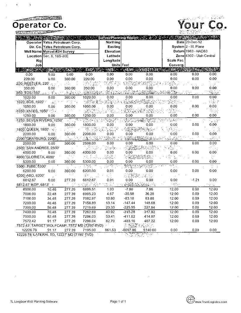
This well will be drilled vertically to 6813'. At 6813' the well will be kicked off and directionally drilled at 12 degrees per 100' with an 8 %" hole to 7572' MD (7290' TVD). The hole size will then be reduced to an 8 1A" hole and drilled to 12227' MD (7195' TVD) where 5 1/2" casing will be set and cemented 500' into the intermediate casing with a Hydraulic DV tool set approximately at 7500' and a DV/Stage Packer tool set between 3750' and 4250'. If the DV/Stage tools are moved the cement will be adjusted proportionately. A packer and ports system will be utilized on this well from TD to 7300'. Penetration point of the producing zone will be encountered at 2247' FNL & 333' FEL, Section 1-T16S-R29E. Deepest TVD in this well is 7290' in the lateral.

Marcel BMM Federal #2H .. . . . . . . . . . . . . . .
Page Two
Minimum Casing Design Factors: Burst 1.0, Tensile Strength 1.8, Collapse 1.12
B. CEMENTING PROGRAM: 13 3/8' Surface Casing: 340 sacks "C" w/CaCI2 (WT 14.80 YLD 1.34). Cement designed with 100% excess. TOC at surface. 9 5/8' Intermediate Casing: 675 sacks 35:65:6PzC (Wt. 12.50 YLD 2.00). Tail in with 200 sacks C w/CaCI2 (Wt 14.80 YLD 1.34). Cement designed with 100% excess. TOC at surface.
5 1/2' PRODUCTION CASING WILL BE CEMENTED IN TWO STAGES:
First Stage: A hydraulic DV tool will be set at approximately 4000'. TOC 4000'. Lead w/530 sacks 35:65:6PzC (WT 12.50 YLD 2.00). Tail in with 100 sacks PecosVILt with D151-CaCo3 Wt.=30% BWOC; D174-Expanding Ce=1.5% BWOC; D046-Antifoam=.2% BWOC; D800-Retarder=.6% BWOC; D112-Fluid Loss=.5% BWCO; D208-Viscosifer =.1% BWOC (WT 13.00 YLD 1.41). Cement designed with 35% excess. Second Stage: TOC 2100'. Lead with 255 sacks 35:65:6PzC (Wt. 12.50 Yld. 2.00). Tail in with 100 sacks Class C with CaCI2 (Wt. 14.80 Yld. 1.34). Cement designed with 35% excess.
Viscosity Fluid Loss 32-34 N/C 28-29 N/C 30-34 N/C
r Sufficient mud material(s) to maintain mud properties, control lost circulation and contain a blow out will be available at the well site during drilling operations. The slow pump speed will be recorded on the daily drilling report after mudding up. A mud test will be performed every 24 hours after mudding up to determine, as applicable: density, viscosity, gel strength, filtration, and pH. After surface casing is set an electronic PVT system will be installed as our primary mud level monitoring system. A secondary system will also be implemented as to insure the PVT system is functioning properly. The secondary system will be comprised of the derrick hand visually checking the fluid level in the pits periodically using a nut on the end of a rope hanging just above the fluid level in the pit.
6. EVALUATION PROGRAM: Samples: 30' samples to 2600' 10' out from under intermediate casing (2600') to TD. Logging: Horizontal MWD / GR TD to surface.. Coring: None anticipated. DST's: None anticipated. MUDLOGGING: Yes from surface to TD. H2S: None anticipated.
5S* 5. Mud Program and Auxiliary Equipment:
Interval . ^ j Type Weight O t a ^ ' T ^ Freshwater 8.60-9.20 32F-2600' Brine Water 10.00-10.20
^ 2600'-12227' Cut Brine (Lateral section) 8.70-9.00

Marcel BMM Federal #2H Page Three
7. ABNORMAL CONDITIONS, BOTTOM HOLE PRESSURE AND POTENTAL HAZARDS:
Anticipated BHP:
From: 0 TO 400'TVD Anticipated Max. BHP: 191 PSI From: 400' TO 2600'TVD Anticipated Max. BHP: 1379 PSI From: 2600' to 7290' TVD Anticipated Max. BHP. 3412 PSI
Abnormal Pressures Anticipated: None Lost Circulation Zones Anticipated: None H2S Zones Anticipated: None Maximum Bottom Hole Temperature: 120° F
8. ANTICIPATED STARTING DATE:
Plans are to drill this well as soon as possible after receiving approval. It should take approximately 45 days to drill the well with completion taking another 30 days.
Operator Co,
WW: ^Survey/Plarin ng'Report ^Si'W&rfr*?'^. Operator Yates Petroleum Corp. Northing Date 20-Dec-12
Dir. Co. Yates Petroleum Corp. Easting System 2 - St. Plane
Well Name Marcel #2H Survey Elevation Datum 1983-NAD83
Location Sec. 6, 16S-30E Latitude Zone 4302 - Utah Central
Rig Longitude Scale Fac.
Job Units Feet Converg.
. TjjjiijSff M P i 0.00 0.00 0.00 0.00 0.00 0.00 0.00 0.00 0.00 0.00
220.00 0.00 360.00 220.00 0.00 0.00 0.00 0.00 0.00 0.00
220:;'RLj^TLER,220' -
• " •mm 350.00
:35b: JOSV350', „ , 0.00 360.00
1020.00 0.00 360.00
;i020:':Bbs, 1.020'• ^ .. - •
1050.00 0.00 360.00
i:;YATES, 1050' ' •
1250.00 0.00 360.00
350.00 0.00 0.00 0.00 0.00 0.00
1020.00 0.00 0.00 0.00 0.00 0.00
1050.00 0.00 0.00 0.00 0.00 0.00
1250.00 0.00 0.00 0.00 0.00 0.00
.1250: SEVEN RIVERS,'1250' ;
' 1800.00 0.00 360.00
,18Qp:.QUEEN,1800' .
2200.00 0.00 360.00 ,2200!-gRAYBURG,2200'
1800.00 0.00
2200.00 0.00 0.00 0.00
0.00 0.00
0.00
0.00
0.00
o.oo —rr—:—:
0.00
0.00
0.00
0.00
2500.00 0.00 360.00 2500.00 0.00
.250,0:,SAN ANDRES, 2500' Vi':>^ ' • ' ^ ' 0 ' 4000.00 0.00 360.00 4000.00 0.00
4000: GLORIETA, 4000' "\v-V • - X , . • -5300.00 0.00 360.00 5300.00 0.00
0.00 0.00
msmmmz. 0.00 0.00
0.00 0.00
0.00
0.00
0.00
0.00
0.00
0.00
0.00
0.00
0.00
0.00
0.00 5300: TUBB,'5300' -
• '•:>-. '6200.00 0.00 360.00 6200.00 0.01 0.00 0.00 0.00 0.00 0.00
6200:'ABO, 6200' f . • : . . • V'.i'. u :" 6812.67 0.00 277.39 6812.67 0.01 0.00 0.00 0.00 -1.21 0.00
6812.67: ;K0P, 6813' •? ; sir.
6900.00 10.48 277.39 6899.51 1.03 -7.90 7.96 12.00 0.00 12.00
7000.00 22.48 277.39 6995.23 4.67 -35.98 36.28 12.00 0.00 12.00
7100.00 34.48 277.39 7082.97 10.80 -83.18 83.88 12.00 0.00 12.00
7200.00 46.48 277.39 7158.89 19.14 -147.44 148.68 12.00 0.00 12.00 7300.00 58.48 277.39 7219.69 29.33 -225.95 227.84 12.00 0.00 12.00
7400.00 70.48 277.39 7262.69 40.92 -315.28 317.92 12.00 0.00 12.00
7500.00 82.48 277.39 7286.03 53.41 -411.52 414.97 12.00 0.00 12.00 7572.42 91.17 277.39 7290.04 62.70 -483.16 487.22 12.00 0.00 12.00
7572.42: TARGET WOl FCAMP, 7572' MD (7290' TVD) r '%v<; ' • 12226.78 91.17 277.39 7195.00 661.53 -5097.86 5140.60 0.00 0.00 0.00
12226.78: LATERAL TD, 12227'MD (7195'TVD) ' • US •T '
TL Longbow Well Planning Software Page 1 of 1 V^J-^ www. TrantLogistics.com

2000 2000 ! !
-xuuu - : ! 1
1 ;
f .j ; 1000 1000
Z — ...j__4_ *!! —Marce l 2h Survey
0 • u 1 ' ' : i !
r \ i_p i L x r \ , ""I""j"" i
! ! i : i ;
-1000 : ! : : i : -1000
6000 _ 5000 4000 -3000 -2000 1000 0 1000
1 nnn +E/W-J.UUU
1 YATES,! 1050' BOS, 1020' j
SEVEN RIV ERS, 12 50'
j j
-QljfEE)jjr-l$O0' ?nnn
-QljfEE)jjr-l$O0'
! | | | f ri A\ / r i I i rifr- i h n n
SA N A NDf^ES, |250 D' I I
j i ouuu • i
i
i j
TV
D
j L
r~l i—rn ! A r\r\r,1 4 U U U
; : ; 1
i |
! i J U U U : : j
TL BB,|5300'
i i
; ; i :
DUUU
( | ]
-KC i ! —Marcel #2H Survey
7nnn -KC r, D 31.3!
i j i / uuu
\ J li TERAL TD, j.22^7' 1 /ID
ET
-MI
WO
47; .-Fe on;
\MF>-75
-TVO)
(71 35' jrvDj) ET
-MI
WO
47; .-Fe on;
\MF>-75
-TVO) i : i
ET
-MI
WO
47;
8000 1
-10 00 C ) 10 oo 20 00 30 00 40 00 50 00 60 00
TL Longbow Well Planning Software viiywww.TrantLogislics.com

r Yates Petroleum-Corporation
Typical 3.000 psi Pressure System . Schematic
Annular with Double Ram Preventer Stack
BOP-3
Kcllv
Fill Up Line
Flow Line
Annular Preventer
Blind Rams
Pipe Rams
Choke Line
Check Valve sequence optional
Intermediate Casing Well Head
Intermediate Casing
Typical 3,000 psi choke manifold assembly with at least these minimiui features
Adjustable choke •• m * m * To'pit'Und/or'tnud gas seperator
To blowout preventer stack Choke line
Y -A XL
3* nun.
fixji= Bleed Line
CTO To pit and/or mud gas seperator
Adjustable choke N
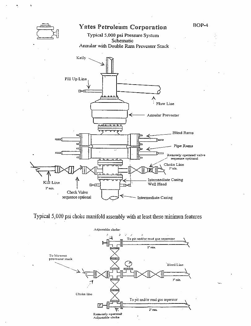
B Yates PettroSeiflinn) Corporation
Typical 5.000 psi Pressure System Schematic
Annular with Double Ram Preventer Stack
BOP-4
Kellv
Fill Up Line
Y • X T
" n " " " 2
< -
; Flow Line
Annular Preventer
n n t n n n h n "
U 11 D U 11
5KLMILXI . n rt - i " " "
1 u J u u u
- I T - i n
U J u u u
- I T - i n 1 n
J u u u
- I T - i n
K i l l Line 2* min.
u u u—u u M < ^
DXHZ
_ Blind Rams
Pipe Rams
Remotely operated v a l v e sequence op t iona l
Check Valve sequence optional
\ Choke Line
Intermediate Casing Well Head
Intermediate Casing
Typical 5,000 psi choke manifold assembly with at least these minimun features
Adjustable choke
To p i t and/or mud gas separator
T o b lowou t preventer stack
rr Choke line
2" man.
Bleed L ine
ai><0̂ i><aixo 3" min.
Remotely operated-Adjustable choke
To pit and/or mud gas seperator
2* min.

YATES PETROLEUM CORPORATION Piping from Choke Manifold
to the Closed Loop Drilling Mud System
GROUND LEVEL
The flare discharge must be 100' from wellhead for non H2S wells and 150' from wellhead for wells expected to encounter H2S.
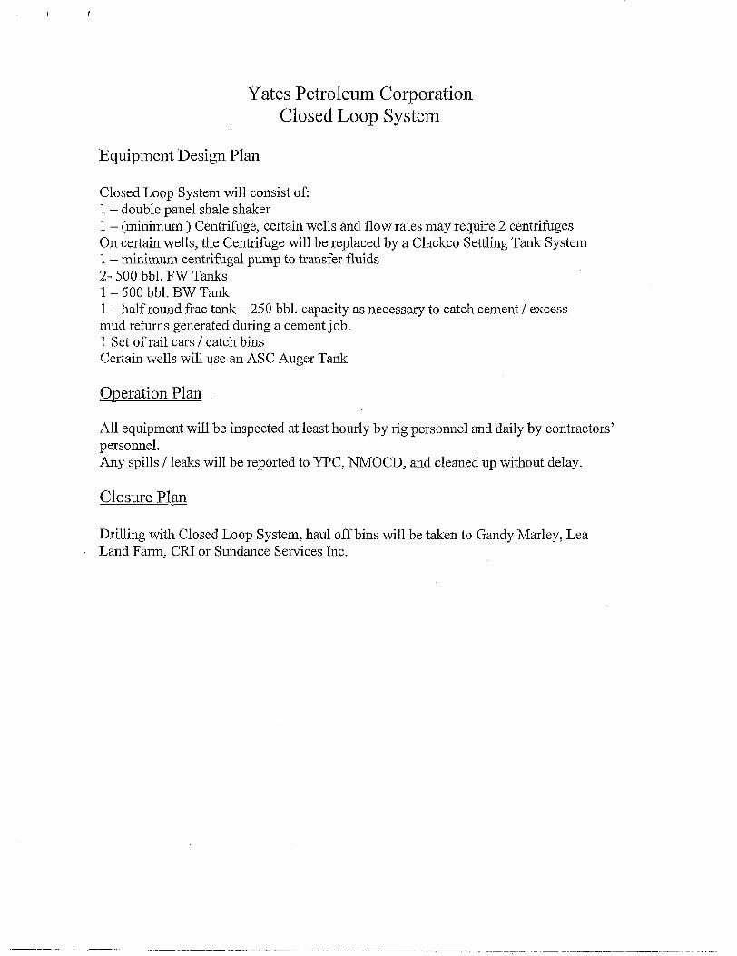
Yates Petroleum Corporation Closed Loop System
Equipment Design Plan
Closed Loop System will consist of: 1 - double panel shale shaker 1 - (minimum ) Centrifuge, certain wells and flow rates may require 2 centrifuges On certain wells, the Centrifuge will be replaced by a Clackco Settling Tank System 1 — minimum centrifugal pump to transfer fluids 2- 500 bbl. FW Tanks 1 - 500 bbl. BW Tank 1 - half round frac tank - 250 bbl. capacity as necessary to catch cement / excess mud returns generated during a cement job. 1 Set of rail cars / catch bins Certain wells will use an ASC Auger Tank
Operation Plan
All equipment will be inspected at least hourly by rig personnel and daily by contractors' personnel.
Any spills / leaks will be reported to YPC, NMOCD, and cleaned up without delay.
Closure Plan
Drilling with Closed Loop System, haul off bins will be taken to Gandy Marley, Lea Land Farm, CRI or Sundance Services Inc.

DISTRICT I - 1625 N. French Dr.. Hobbs, Nil 88240
DISTRICT I I 1301 V. Grand Avenue, Artesia, NU 88210
DISTRICT I I I 1000 Rio Brazos Rd., Aztec, NU 87410
DISTRICT IV 1220 S. St. Francis Dr., Santa Fe, Nil 87505
State o f New Mexico Energy, Minerals and Natural Resources Department
O I L C O N S E R V A T I O N D I V I S I O N 1220 South St. Francis Dr.
Santa Fe, New Mexico 87505
Form C-102 Revised October 12, 2005
Submit to Appropriate District Office State Lease - 4 Copies
Fee Lease - 3 Copies
• AMENDED REPORT
WELL LOCATION AND ACREAGE DEDICATION PLAT API Number Pool Code Pool Name
Undesignated Wofcamp
Property Code Property Name TTell Number
MARCEL "BMM" FEDERAL 2H OGRID No. Operator Name Elevation
025575 YATES PETROLEUM CORP. 3798' Surface Location
UL or lot No.
LOT 5 Section
6 Township
16 S Range
30 E Lot Idn Feet from the
2310 North/South line
NORTH Feet from the
150 East/West line
WEST County
EDDY
Bottom Hole Location If Different From Surface UL or lot No.
LOT 5 Section
1 Township
16 S Range
29 E Lot Idn Feet from the
1650 North/South line
NORTH Feet from the
330 East/West line
WEST County
EDDY Dedicated Acres
160
Joint or Infill Consolidation Code Order No.
NO ALLOWABLE WILL BE ASSIGNED TO THIS COMPLETION UNTIL ALL INTERESTS HAVE BEEN CONSOLIDATED
OR A NON-STANDARD UNIT HAS BEEN APPROVED BY THE DIVISION
BOTTOM HOLE LOCATION Lat - N32*57 '39 .0r Long - W104'02'08.69"
SPC- nt.: 713417.119 E.: 632611.025 (NAD-83)
SURFACE LOCATION Lat - N32 , 57'32.32" Long - W104*0r08.88"
N.: 712755.598 E.: 637708.888 (NAD-83)
SPC
Project A
Produciri;
T Zone^
'entetration Point 2247' FNL̂ c 333 ' FEL
OPERATOR CERTIFICATION
/ hereby certify that the information contained herein is true and complete to the best of my knowledge and belief, and that this organization either owns a working interest or unleased mineral interest in the land including the proposed bottom hole location pursuant to a contract with an owner of such a mineral or working interest, or to a voluntary pooling agreement or a compulsory poolingyxrder heretofore entered by the div'~*
Signat^-e
Cy Cowan
Printed Name
SURVEYOR CERTIFICATION
/ hereby certify that the well location shown on this plat was plotted from field notes of actual surveys made by me or under my supervisory and that the same is true and correct to the best of my belief.
SCALE - 1" = 2000' Certificate No. Gary L. Jones 7977
BASIN SURVEYS
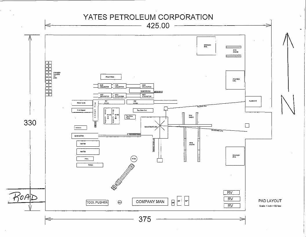
YATES PETROLEUM CORPORATION 425.00
X
• • • • • • • • • • • • • • • • • • • • • •
MUD COLLECTOR
MUD COLLECTOR
| CENRTFUGE | CENRTFUGE IIIIIIIIIHIKIIIIM
MUD COLLECTOR
MUD COLLECTOR
330
FRAC TANK M prr
UX 50 U D
Mud Hopper rt o
M
u M U
u s E
D 1*1/2
p x
u 3 0
M p
0 141/2 P X
u 3 0
M P
D 1*1/2
p x
u 3 0
M p
0 141/2 P X
u 3 0
M P
GENERATOR
i . PAD LAYOUT Scale: 1 inch = 50 feet
375
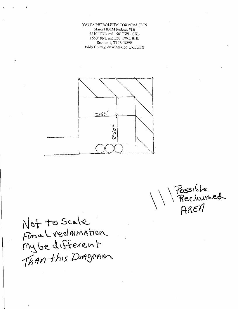
YATES PETROLEUM CORPORATION Marcel BMM Federal #1H
2310'FNL and 150'FWL SHL 1650' FNL and 330' FWL BHL
Section 1,T16S-R29E Eddy County, New Mexico Exhibit X

MULTI-POINT SURFACE USE AND OPERATIONS PLAN Yates Petroleum Corporation
Marcel BMM Federal #2H 2310' FNL and 150' FEL, Section 6, 16S-30E (Surface Hole Location) 1650' FNL and 330' FWL, Section 1, 16S-29E (Bottom Hole Location)
Eddy County, New Mexico
This plan is submitted with Form 3160-3, Application for Permit to Drill, covering the above described well. The purpose of this plan is to describe the location of the proposed well, the proposed construction activities and operations plan, the magnitude of the surface disturbance involved and the procedures to be followed in rehabilitating the surface after completion of the operations, so that a complete appraisal can be made of the environmental effect associated with the operations.
1. EXISTING ROADS:
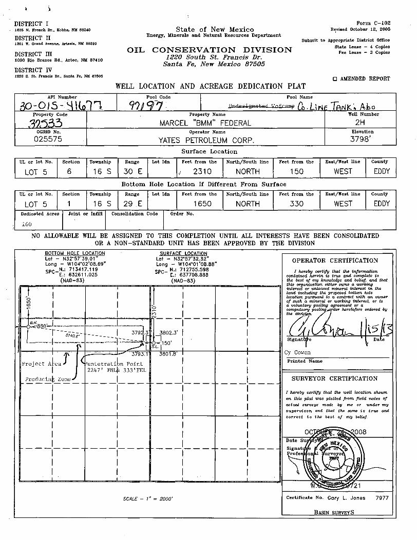
Exhibit A is a portion of the BLM map showing the well and roads in the vicinity of the proposed location. The proposed well site is located approximately 34 miles east of Artesia, New Mexico and the access route to the location is indicated in red and green on Exhibit A.
DIRECTIONS:
From Loco Hills, NM go north on the Hagerman Cutoff for approximately 9.7 miles. There will be a Chaves County Line marker at this point and a lease road going to the left. Turn left here on the lease road and go approximately 1.3 miles. At this point there will be a lease road on the left going southwest along a pipeline right of way. Turn left here and follow the lease road for approximately 1.1 miles. At this point the Marcell BMM Federal #1H and a frac reservoir will be on the left. The new road will start here going south along the pipeline right of way for approximately .3 of a mile. At this point the new access road will go to the left for approx. .4 of a mile to the southwest corner of the well location.
2. PLANNED ACCESS ROAD:
A. The proposed new road will go in a southwesterly direction for about .3 of a mile along an existing pipeline. At this point the new road will go east for approximately .4 of a mile to the southwest corner of the drilling pad.
B. The new road will be 14' in width (driving surface) and will be adequately drained to control runoff and soil erosion.
C. The new road will be bladed with drainage on one side. Traffic turnouts may be built. D. The route of the road is visible. E. Existing roads will be maintained in the same or better condition.
3. LOCATION OF EXISTING WELL
A. There is drilling activity within a one-mile radius of the well site. B. An Exhibit shows existing wells within a one-mile radius of the proposed well site.
4. LOCATION OF EXISTING AND/OR PROPOSED FACILITIES
A. There are production facilities on this lease at the present time. B. In the event that the well is productive, the necessary production facilities will be
installed on the drilling pad. If the well is productive oil, a gas or diesel self-contained unit will be used to provide the necessary power until an electric power line can be built if needed.

Marcel BMM Federal #2H Page Two
5. LOCATION AND TYPE OF WATER SUPPLY:
A. It is planned to drill the proposed well with a fresh water system. The water will be obtained from commercial sources and will be hauled to the location by truck over the existing and proposed roads shown in Exhibit A.
6. SOURCE OF CONSTRUCTION MATERIALS:
The dirt contractor will acquire any materials from the closest source at the time of construction of the well pad.
7. METHODS OF HANDLING WASTE DISPOSAL:
A. This well will be drilled with a closed loop system B. The closed loop system will be constructed, maintained, and closed in compliance with
the State of New Mexico, Energy and Natural Resources Department, Oil Conservation Division-the "Pit Rule" 19.15.17 NMAC.
C Drilling fluids will be removed after drilling and completions are completed. D. Water produced during operations will be collected in tanks until hauled to an approved
disposal system, or separate disposal application will be submitted. E. Oil produced during operations will be stored in tanks until sold. F. Current laws and regulations pertaining to the disposal of human waste will be complied
with. G. All trash, junk, and other waste materials will be contained in trash cages or bins to
prevent scattering and will be removed and deposited in an approved sanitary landfill. Burial on site is not approved.
8. ANCILLARY FACILITIES: None
9. WELLSITE LAYOUT:
A. Exhibit C shows the relative location and dimensions of the well pad, location of the drilling equipment, pulling unit orientation and access road approach. The closed loop system will be constructed, maintained, and closed in compliance with the State of New Mexico, Energy and Natural Resources Department, Oil Conservation Division - the "Pit Rule" 19.15.17 NMAC.
B. A 600' x 600' area has been staked and flagged.
10. PLANS FOR RESTORATION
A. After finishing drilling and/or completion operations, all equipment and other material not needed for further operations will be removed. The location will be cleaned of all trash and junk to leave the well site in as aesthetically pleasing a condition as possible.
B. Unguarded pits, if any, containing fluids will be fenced until they have dried and been leveled.
C. If the proposed well is non-productive, all rehabilitation and/or vegetation requirements of the Bureau of Land Management will be complied with and will be accomplished as expeditiously as possible. All pits will be filled level within 90 days after abandonment.
Marcel BMM Federal #2H Page Three
11. SURFACE OWNERSHIP:
Surface Estate Bureau of Land Management 620 East Greene Street, Carlsbad, NM 88220.
Mineral Estate: Bureau of Land Management 620 East Greene Street, Carlsbad, NM 88220
12. OTHER INFORMATION:
A. Topography: Refer to the existing archaeological report for a description of the topography, flora, fauna, soil characteristics, dwellings, historical and cultural sites.
B. The primary surface use is for grazing.
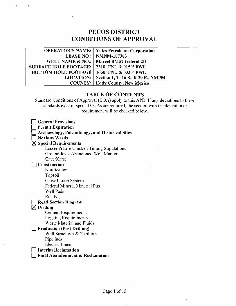
PECOS DISTRICT CONDITIONS OF APPROVAL
OPERATOR'S NAME: Yates Petroleum Corporation LEASE NO.: NMNM-107383
WELL NAME & NO.: Marcel BMM Federal 2H SURFACE HOLE FOOTAGE: 2310' FNL & 0150' FWL
BOTTOM HOLE FOOTAGE 1650' FNL & 0330' FWL LOCATION: Section 1, T. 16 S., R 29 E. , NMPM
COUNTY: Eddy County, New Mexico
T A B L E O F C O N T E N T S Standard Conditions of Approval (COA) apply to this APD. If any deviations to these
standards exist or special COAs are required, the section with the deviation or requirement will be checked below.
I I General Provisions I | Permit Expiration I I Archaeology, Paleontology, and Historical Sites I I Noxious Weeds 1X1 Special Requirements
Lesser Prairie-Chicken Timing Stipulations Ground-level Abandoned Well Marker Cave/Karst
I I Construction Notification Topsoil Closed Loop System Federal Mineral Material Pits Well Pads Roads
I I Road Section Diagram IEI Drilling
Cement Requirements Logging Requirements Waste Material and Fluids
I I Production (Post Drilling) Well Structures & Facilities Pipelines Electric Lines
I I Interim Reclamation I I Final Abandonment & Reclamation
Page 1 of 15

I. GENERAL PROVISIONS
The approval of the Application For Permit To Drill (APD) is in compliance with all applicable laws and regulations: 43 Code of Federal Regulations 3160, the lease terms, Onshore Oil and Gas Orders, Notices To Lessees, New Mexico Oil Conservation Division (NMOCD) Rules, National Historical Preservation Act As Amended, and instructions and orders of the Authorized Officer. Any request for a variance shall be submitted to the Authorized Officer on Form 3160-5, Sundry Notices and Report on Wells.
II. PERMIT EXPIRATION
If the permit terminates prior to drilling and drilling cannot be commenced within 60 days after expiration, an operator is required to submit Form 3160-5, Sundry Notices and Reports on Wells, requesting surface reclamation requirements for any surface disturbance. However, if the operator will be able to initiate drilling within 60 days after the expiration of the permit, the operator must have set the conductor pipe in order to allow for an extension of 60 days beyond the expiration date of the APD. (Filing of a Sundry Notice is required for this 60 day extension.)
III. ARCHAEOLOGICAL, PALEONTOLOGY & HISTORICAL SITES
Any cultural and/or paleontological resource discovered by the operator or by any person working on the operator's behalf shall immediately report such findings to the Authorized Officer. The operator is fully accountable for the actions of their contractors and subcontractors. The operator shall suspend all operations in the immediate area of such discovery until written authorization to proceed is issued by the Authorized Officer. An evaluation of the discovery shall be made by the Authorized Officer to determine the appropriate actions that shall be required to prevent the loss of significant cultural or scientific values of the discovery. The operator shall be held responsible for the cost of the proper mitigation measures that the Authorized Officer assesses after consultation with the operator on the evaluation and decisions of the discovery. Any unauthorized collection or disturbance of cultural or paleontological resources may result in a shutdown order by the Authorized Officer.
IV. NOXIOUS WEEDS
The operator shall be held responsible if noxious weeds become established within the areas of operations. Weed control shall be required on the disturbed land where noxious weeds exist, which includes the roads, pads, associated pipeline corridor, and adjacent land affected by the establishment of weeds due to this action. The operator shall consult with the Authorized Officer for acceptable weed control methods, which include following EPA and BLM requirements and policies.
Page 2 of 15
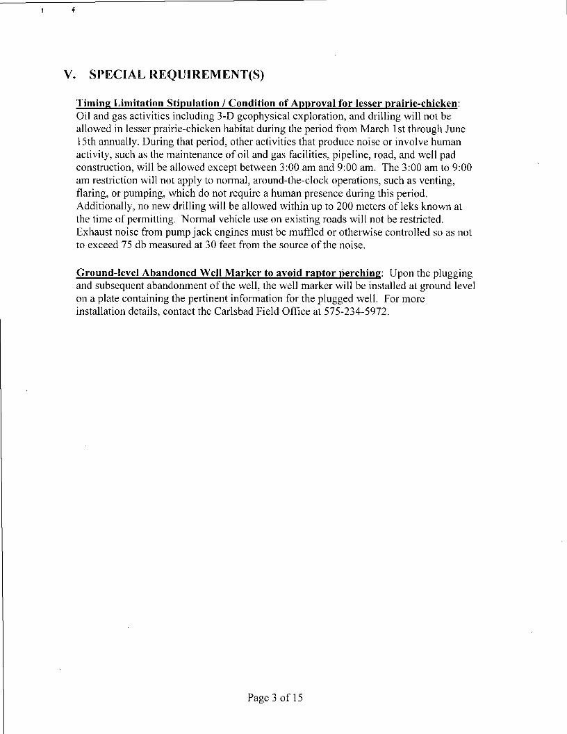
V. SPECIAL REQUIREMENT(S)
Timing Limitation Stipulation / Condition of Approval for lesser prairie-chicken: Oil and gas activities including 3-D geophysical exploration, and drilling will not be allowed in lesser prairie-chicken habitat during the period from March 1st through June 15th annually. During that period, other activities that produce noise or involve human activity, such as the maintenance of oil and gas facilities, pipeline, road, and well pad construction, will be allowed except between 3:00 am and 9:00 am. The 3:00 am to 9:00 am restriction will not apply to normal, around-the-clock operations, such as venting, flaring, or pumping, which do not require a human presence during this period. Additionally, no new drilling will be allowed within up to 200 meters of leks known at the time of permitting. Normal vehicle use on existing roads will not be restricted. Exhaust noise from pump jack engines must be muffled or otherwise controlled so as not to exceed 75 db measured at 30 feet from the source of the noise.
Ground-level Abandoned Well Marker to avoid raptor perching: Upon the plugging and subsequent abandonment of the well, the well marker will be installed at ground level on a plate containing the pertinent information for the plugged well. For more installation details, contact the Carlsbad Field Office at 575-234-5972.
Page 3 of 15
VI. CONSTRUCTION
A. NOTIFICATION
The BLM shall administer compliance and monitor construction of the access road and well pad. Notify the Carlsbad Field Office at (575) 234-5909 at least 3 working days prior to commencing construction of the access road and/or well pad.
When construction operations are being conducted on this well, the operator shall have the approved APD and Conditions of Approval (COA) on the well site and they shall be made available upon request by the Authorized Officer.
B. TOPSOIL
The operator shall stockpile the topsoil in a low profile manner in order to prevent wind/water erosion of the topsoil. The topsoil to be stripped is approximately 6 inches in depth. The topsoil will be used for interim and final reclamation.
C. CLOSED LOOP SYSTEM
Tanks are required for drilling operations: No Pits.
The operator shall properly dispose of drilling contents at an authorized disposal site.
D. FEDERAL MINERAL MATERIALS PIT
Payment shall be made to the BLM prior to removal of any federal mineral materials. Call the Carlsbad Field Office at (575) 234-5972.
E. WELL PAD SURFACING
Surfacing of the well pad is not required.
If the operator elects to surface the well pad, the surfacing material may be required to be removed at the time of reclamation.
The well pad shall be constructed in a manner which creates the smallest possible surface disturbance, consistent with safety and operational needs.
F. ON LEASE ACCESS ROADS
Road Width The access road shall have a driving surface that creates the smallest possible surface disturbance and does not exceed fourteen (14) feet in width. The maximum width of surface disturbance, when constructing the access road, shall not exceed twenty-five (25) feet.
Page 4 of 15

Surfacing Surfacing material is not required on the new access road driving surface. If the operator elects to surface the new access road or pad, the surfacing material may be required to be removed at the time of reclamation.
Where possible, no improvements should be made on the unsurfaced access road other than to remove vegetation as necessary, road irregularities, safety issues, or to fill low areas that may sustain standing water.
The Authorized Officer reserves the right to require surfacing of any portion of the access road at any time deemed necessary. Surfacing may be required in the event the road deteriorates, erodes, road traffic increases, or it is determined to be beneficial for future field development. The surfacing depth and type of material will be determined at the time of notification.
Crowning Crowning shall be done on the access road driving surface. The road crown shall have a grade of approximately 2% (i.e., a 1" crown on a 14' wide road). The road shall conform to Figure 1; cross section and plans for typical road construction.
Ditching
Ditching shall be required on both sides of the road.
Turnouts Vehicle turnouts shall be constructed on the road. Turnouts shall be intervisible with interval spacing distance less than 1000 feet. Turnouts shall be constructed on all blind curves. Turnouts shall conform to the following diagram:
• if'' • "^-c:r'-' T^S^-TF* ^Cepterl ineic^:£pi^ • - y
Drainage Drainage control systems shall be constructed on the entire length of road (e.g. ditches, sidehill outsloping and insloping, lead-off ditches, culvert installation, and low water crossings).
A typical lead-off ditch has a minimum depth of 1 foot below and a berm of 6 inches above natural ground level. The berm shall be on the down-slope side of the lead-off ditch.
Cross Section of a Typical Lead-off Ditch
Page 5 of 15
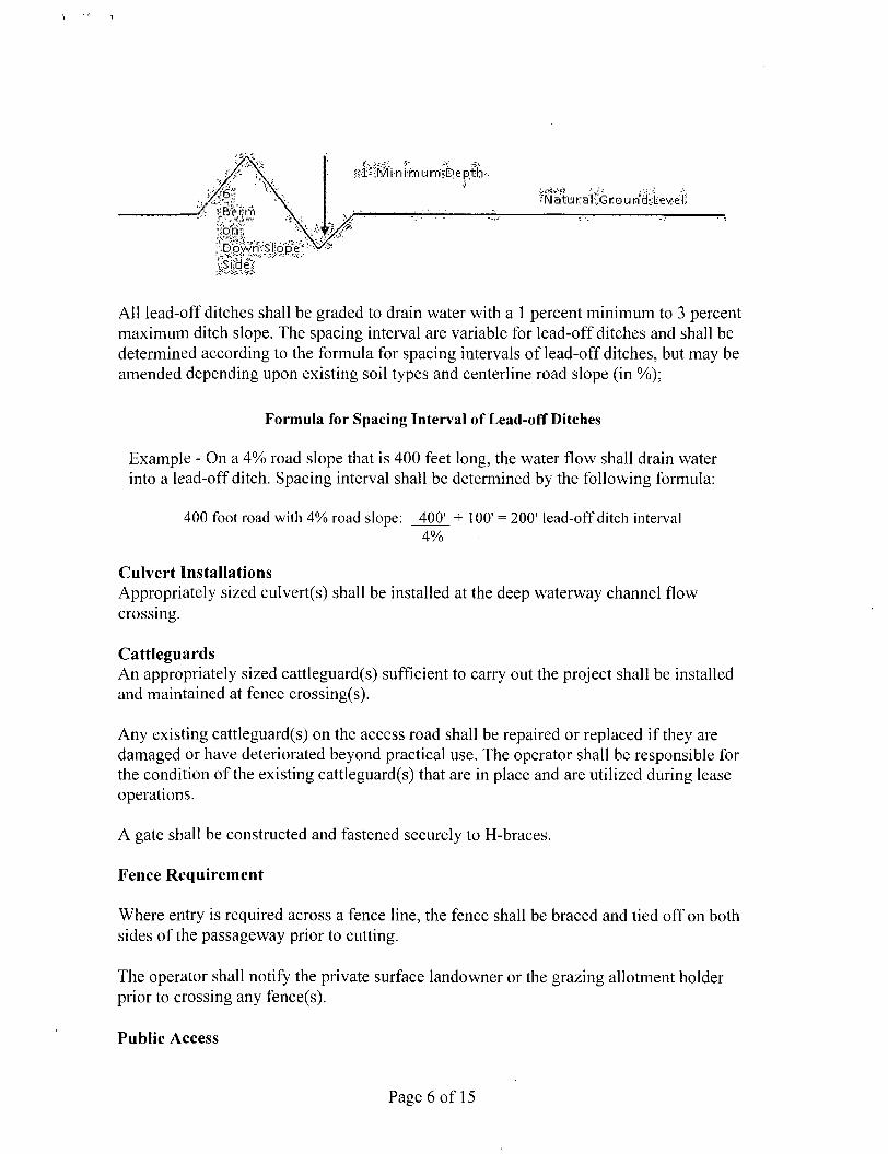
All lead-off ditches shall be graded to drain water with a 1 percent minimum to 3 percent maximum ditch slope. The spacing interval are variable for lead-off ditches and shall be determined according to the formula for spacing intervals of lead-off ditches, but may be amended depending upon existing soil types and centerline road slope (in %);
Formula for Spacing Interval of Lead-off Ditches
Example - On a 4% road slope that is 400 feet long, the water flow shall drain water into a lead-off ditch. Spacing interval shall be determined by the following formula:
400 foot road with 4% road slope: 400' + 100' = 200' lead-off ditch interval 4%
Culvert Installations Appropriately sized culvert(s) shall be installed at the deep waterway channel flow crossing.
Cattleguards An appropriately sized cattleguard(s) sufficient to carry out the project shall be installed and maintained at fence crossing(s).
Any existing cattleguard(s) on the access road shall be repaired or replaced if they are damaged or have deteriorated beyond practical use. The operator shall be responsible for the condition of the existing cattleguard(s) that are in place and are utilized during lease operations.
A gate shall be constructed and fastened securely to H-braces.
Fence Requirement
Where entry is required across a fence line, the fence shall be braced and tied off on both sides of the passageway prior to cutting.
The operator shall notify the private surface landowner or the grazing allotment holder prior to crossing any fence(s).
Public Access
Page 6 of 15
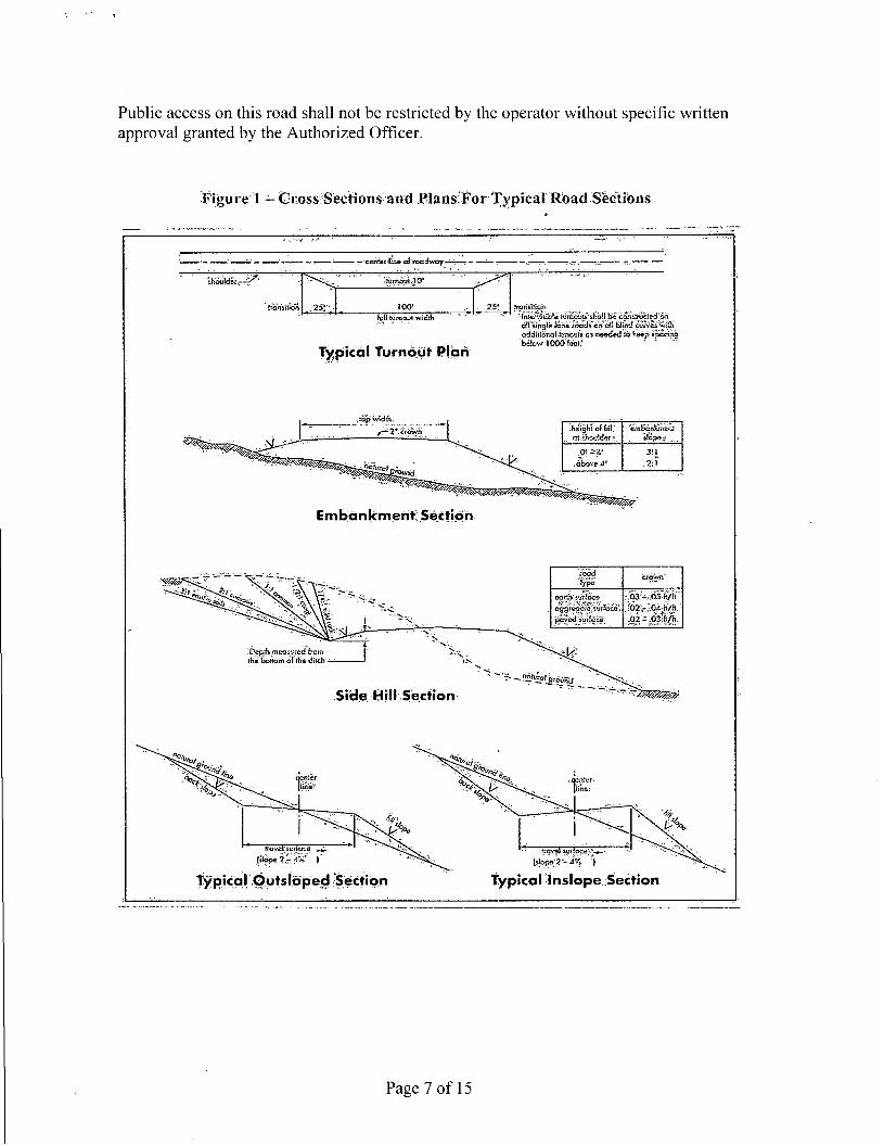
Public access on this road shall not be restricted by the operator without specific written approval granted by the Authorized Officer.
Figure1 - Gross ̂ Sections and PlansiFor Typical "Road Sections
' tnJeryijibfe ^Iroobri ihoQ be <^5fir^(&*c«' a?i'sing!s Icrre roods'cn cli blind curves win addirronqltonouis as needed to tiep ipaonQ 'below 1000feci?
transition ;25!'" Ml himouf.widlJj
Typical. Turnout Plan
,top width, .heighlof fill! ai ihcylder
•embonwneni
.above 4' 3:1 2:\
Embankment Section
Page 7 of 15

DRILLING
A. DRILLING OPERATIONS REQUIREMENTS
The BLM is to be notified in advance for a representative to witness:
a. Spudding well (minimum of 24 hours) b. Setting and/or Cementing of all casing strings (minimum of 4 hours) c. BOPE tests (minimum of 4 hours)
IE Eddy County Call the Carlsbad Field Office, 620 East Greene St., Carlsbad, NM 88220, (575) 361-2822
1. Although Hydrogen Sulfide has not been reported in the area, it is always a potential hazard. If Hydrogen Sulfide is encountered, report measured amounts and formations to the BLM.
2. Unless the production casing has been run and cemented or the well has been properly plugged, the drilling rig shall not be removed from over the hole without prior approval. If the drilling rig is removed without approval - an Incident of Non-Compliance will be written and will be a "Major" violation.
3. Floor controls are required for 3M or Greater systems. These controls will be on the rig floor, unobstructed, readily accessible to the driller and will be operational at all times during drilling and/or completion activities. Rig floor is defined as the area immediately around the rotary table; the area immediately above the substructure on which the draw works is located, this does not include the dog house or stairway area.
4. The record of the drilling rate along with the GR/N well log run from TD to surface (horizontal well - vertical portion of hole) shall be submitted to the BLM office as well as all other logs run on the borehole 30 days from completion. If available, a digital copy of the logs is to be submitted in addition to the paper copies. The Rustler top and top and bottom of Salt are to be recorded on the Completion Report.
B. CASING
Changes to the approved APD casing program need prior approval if the items substituted are of lesser grade or different casing size. The Operator can exchange the components of the proposal with that of superior strength (i.e. changing from J-55 to N-80, or from 36# to 40#). Changes to the approved cement program need prior approval if the altered cement plan has less volume or strength or if the changes are substantial (i.e. Multistage tool, ECP, etc.).
Page 8 of 15
1
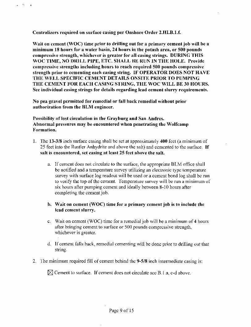
Centralizers required on surface casing per Onshore Order 2.III.B.l.f.
Wait on cement (WOC) time prior to drilling out for a primary cement job will be a minimum 18 hours for a water basin, 24 hours in the potash area, or 500 pounds compressive strength, whichever is greater for all casing strings. DURING THIS WOC TIME, NO DRILL PIPE, ETC. SHALL BE RUN IN THE HOLE. Provide compressive strengths including hours to reach required 500 pounds compressive strength prior to cementing each casing string. IF OPERATOR DOES NOT HAVE THE WELL SPECIFIC CEMENT DETAILS ONSITE PRIOR TO PUMPING THE CEMENT FOR EACH CASING STRING, THE WOC WILL BE 30 HOURS. See individual casing strings for details regarding lead cement slurry requirements.
No pea gravel permitted for remedial or fall back remedial without prior authorization from the BLM engineer.
Possibility of lost circulation in the Grayburg and San Andres. Abnormal pressures may be encountered when penetrating the Wolfcamp Formation.
1. The 13-3/8 inch surface casing shall be set at approximately 400 feet (a minimum of 25 feet into the Rustler Anhydrite and above the salt) and cemented to the surface. If salt is encountered, set casing at least 25 feet above the salt.
a. If cement does not circulate to the surface, the appropriate BLM office shall be notified and a temperature survey utilizing an electronic type temperature survey with surface log readout will be used or a cement bond log shall be run to verify the top of the cement. Temperature survey will be run a minimum of six hours after pumping cement and ideally between 8-10 hours after completing the cement job.
b. Wait on cement (WOC) time for a primary cement job is to include the lead cement slurry.
c. Wait on cement (WOC) time for a remedial job will be a minimum of 4 hours after bringing cement to surface or 500 pounds compressive strength, whichever is greater.
d. If cement falls back, remedial cementing will be done prior to drilling out that string.
2. The minimum required fill of cement behind the 9-5/8 inch intermediate casing is:
E] Cement to surface. If cement does not circulate see B.l .a, c-d above.
Page 9 of 15
Formation below the 9-5/8" shoe to be tested according to Onshore Order 2.III.B.l.i. Test to be done as a mud equivalency test using the mud weight necessary for the pore pressure of the formation below the shoe (not the mud weight required to prevent dissolving the salt formation) and the mud weight for the bottom of the hole. Report results to BLM office.
Centralizers required on horizontal leg, must be type for horizontal service and a minimum of one every other joint.
3. The minimum required fil l of cement behind the 5-1/2 inch production casing is:
Operator has proposed DV tool at depths of 4000', but will adjust cement proportionately if moved. The DV tool at 4000' shall be set a minimum of 50' below previous shoe and a minimum of 200' above current shoe. Operator shall submit sundry if DV tool depth cannot be set in this range.
a. First stage to DV tool:
E Cement to circulate. If cement does not circulate, contact the appropriate BLM office before proceeding with second stage cement job. Operator should have plans as to how they will achieve circulation on the next stage.
b. Second stage above DV tool:
E Cement should tie-back at least 500 feet into previous casing string. Operator shall provide method of verification.
If hardband drill pipe is rotated inside casing, returns will be monitored for metal. If metal is found in samples, drill pipe will be pulled and rubber protectors which have a larger diameter than the tool joints of the drill pipe will be installed prior to continuing drilling operations.
C. PRESSURE CONTROL
1. All blowout preventer (BOP) and related equipment (BOPE) shall comply with well control requirements as described in Onshore Oil and Gas Order No. 2 and API RP 53 Sec. 17.
2. Minimum working pressure of the blowout preventer (BOP) and related equipment (BOPE) required for drilling below the surface casing shoe shall be 3000 (3M) psi.
a. For surface casing only: If the BOP/BOPE is to be tested against casing, the wait on cement (WOC) time for that casing is to be met (see WOC statement at start of casing section). Independent service company required.
Page 10 of 15
3. Minimum working pressure of the blowout preventer (BOP) and related equipment (BOPE) required for drilling below the 9-5/8 intermediate casing shoe shall be 5000 (5M) psi. 5M system requires an HCR valve, remote kill line and annular to match. The remote kill line is to be installed prior to testing the system and tested to stack pressure.
4. The appropriate BLM office shall be notified a minimum of 4 hours in advance for a representative to witness the tests.
a. In a water basin, for all casing strings utilizing slips, these are to be set as soon as the crew and rig are ready and any fallback cement remediation has been done. The casing cut-off and BOP installation can be initiated four hours after installing the slips, which will be approximately six hours after bumping the plug. For those casing strings not using slips, the minimum wait time before cut-off is eight hours after bumping the plug. BOP/BOPE testing can begin after cut-off or once cement reaches 500 psi compressive strength (including lead when specified), whichever is greater. However, if the float does not hold, cut-off cannot be initiated until cement reaches 500 psi compressive strength (including lead when specified).
b. The tests shall be done by an independent service company utilizing a test plug not a cup or J-packer.
c. The test shall be run on a 5000 psi chart for a 2-3M BOP/BOP, on a 10000 psi chart for a 5M BOP/BOPE and on a 15000 psi chart for a 10M BOP/BOPE. If a linear chart is used, it shall be a one hour chart. A circular chart shall have a maximum 2 hour clock.
d. The results of the test shall be reported to the appropriate BLM office.
e. All tests are required to be recorded on a calibrated test chart. A copy of the BOP/BOPE test chart and a copy of independent service company test will be submitted to the appropriate BLM office.
f. The BOP/BOPE test shall include a low pressure test from 250 to 300 psi. The test will be held for a minimum of 10 minutes if test is done with a test plug and 30 minutes without a test plug. This test shall be performed prior to the test at full stack pressure.
g. BOP/BOPE must be tested by an independent service company within 500 feet of the top of the Wolfcamp formation if the time between the setting of the intermediate casing and reaching this depth exceeds 20 days. This test does not exclude the test prior to drilling out the casing shoe as per Onshore Order No. 2.
i
Page 11 of 15

D. DRILLING MUD
Mud system monitoring equipment, with derrick floor indicators and visual and audio alarms, shall be operating before drilling into the Wolfcamp formation, and shall be used until production casing is run and cemented.
E. DRILL STEM TEST
If drill stem tests are performed, Onshore Order 2.III.D shall be followed.
F. WASTE MATERIAL AND FLUIDS
All waste (i.e. drilling fluids, trash, salts, chemicals, sewage, gray water, etc.) created as a result of drilling operations and completion operations shall be safely contained and disposed of properly at a waste disposal facility. No waste material or fluid shall be disposed of on the well location or surrounding area.
Porto-johns and trash containers will be on-location during fracturing operations or any other crew-intensive operations.
JAM 041813
Page 12 of 15

VIII. PRODUCTION (POST DRILLING)
A. WELL STRUCTURES & FACILITIES
Placement of Production Facilities Production facilities should be placed on the well pad to allow for maximum interim recontouring and revegetation of the well location.
Containment Structures The containment structure shall be constructed to hold the capacity of the entire contents of the largest tank, plus 24 hour production, unless more stringent protective requirements are deemed necessary by the Authorized Officer.
Painting Requirement All above-ground structures including meter housing that are not subject to safety requirements shall be painted a flat non-reflective paint color, Shale Green from the BLM Standard Environmental Color Chart (CC-001: June 2008).
VRM Facility Requirement Low-profile tanks not greater than eight-feet-high shall be used.
B. PIPELINES Not applied for in resubmittal permit. C. ELECTRIC LINES Not applied for in resubmittal permit.
IX. INTERIM RECLAMATION
During the life of the development, all disturbed areas not needed for active support of production operations should undergo interim reclamation in order to minimize the environmental impacts of development on other resources and uses.
Within six (6) months of well completion, operators should work with BLM surface management specialists (Jim Amos: 575-234-5909) to devise the best strategies to reduce the size of the location. Interim reclamation should allow for remedial well operations, as well as safe and efficient removal of oil and gas.
During reclamation, the removal of caliche is important to increasing the success of revegetating the site. Removed caliche that is free of contaminants may be used for road repairs, fire walls or for building other roads and locations. In order to operate the well or complete workover operations, it may be necessary to drive, park and operate on restored interim vegetation within the previously disturbed area. Disturbing revegetated areas for production or workover operations will be allowed. If there is significant disturbance and loss of vegetation, the area will need to be revegetated. Communicate with the appropriate BLM office for any exceptions/exemptions if needed.
Page 13 of 15
All disturbed areas after they have been satisfactorily prepared need to be reseeded with the seed mixture provided below.
Upon completion of interim reclamation, the operator shall submit a Sundry Notices and Reports on Wells, Subsequent Report of Reclamation (Form 3160-5).
X. FINAL ABANDONMENT & RECLAMATION
At final abandonment, well locations, production facilities, and access roads must undergo "final" reclamation so that the character and productivity of the land are restored.
Earthwork for final reclamation must be completed within six (6) months of well plugging. All pads, pits, facility locations and roads must be reclaimed to a satisfactory revegetated, safe, and stable condition, unless an agreement is made with the landowner or BLM to keep the road and/or pad intact.
After all disturbed areas have been satisfactorily prepared, these areas need to be revegetated with the seed mixture provided below. Seeding should be accomplished by drilling on the contour whenever practical or by other approved methods. Seeding may need to be repeated until revegetation is successful, as determined by the BLM.
Operators shall contact a BLM surface protection specialist prior to surface abandonment operations for site specific objectives (Jim Amos: 575-234-5909).
Ground-level Abandoned Well Marker to avoid raptor perching: Upon the plugging and subsequent abandonment of the well, the well marker will be installed at ground level on a plate containing the pertinent information for the plugged well.
Page 14 of 15
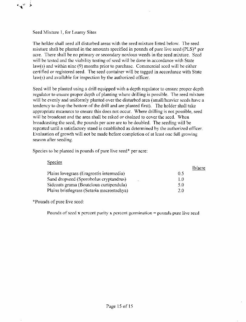
Seed Mixture 1, for Loamy Sites
The holder shall seed all disturbed areas with the seed mixture listed below. The seed mixture shall be planted in the amounts specified in pounds of pure live seed (PLS)* per acre. There shall be no primary or secondary noxious weeds in the seed mixture. Seed will be tested and the viability testing of seed will be done in accordance with State law(s) and within nine (9) months prior to purchase. Commercial seed will be either certified or registered seed. The seed container will be tagged in accordance with State law(s) and available for inspection by the authorized officer.
Seed will be planted using a drill equipped with a depth regulator to ensure proper depth regulator to ensure proper depth of planting where drilling is possible. The seed mixture will be evenly and uniformly planted over the disturbed area (small/heavier seeds have a tendency to drop the bottom of the drill and are planted first). The holder shall take appropriate measures to ensure this does not occur. Where drilling is not possible, seed will be broadcast and the area shall be raked or chained to cover the seed. When broadcasting the seed, the pounds per acre are to be doubled. The seeding will be repeated until a satisfactory stand is established as determined by the authorized officer. Evaluation of growth will not be made before completion of at least one full growing season after seeding.
Species to be planted in pounds of pure live seed* per acre:
*Pounds of pure live seed:
Pounds of seed x percent purity x percent germination = pounds pure live seed
Species lb/acre
Plains lovegrass (Eragrostis intermedia) Sand dropseed (Sporobolus cryptandrus) Sideoats grama (Bouteloua curtipendula) Plains bristlegrass (Setaria macrostachya)
0.5 1.0 5.0 2.0
Page 15 of 15


![LEASE AGREEMENT [LEASE] - Connecticut](https://img.pdfslide.net/doc/110x75/620739c849d709492c2f377a/lease-agreement-lease-connecticut.jpg)

![LEASE AGREEMENT [LEASE] - DAS Splash Page](https://img.pdfslide.net/doc/110x75/61fb31e62e268c58cd5b47fd/lease-agreement-lease-das-splash-page.jpg)