Embed Size (px)
Citation preview

Copyright 1997 by R. Tront 5-1
5. OO Analysis and Design‘Object orientation’ means different things to different people. In this section, I want to de-emphasize the language syntax and the inheritance/polymorphism issues of object orientation, so as to be able to concentrate on object-oriented thinking, OO systems analysis, OO architecture, and OO design. This will allow you to better envision an object-oriented design architecture in its proper form: Each external request made of a system is implemented by a sequence of messages which flow among a set of reactive software abstractions. The importance and utility of this vision of a system’s architecture is under-emphasized by most authors, but is key to understanding object orientation.
The section will also discuss some other general object-oriented issues like object modelling, encapsulation, abstraction, and even ‘impedance mismatches’ between the various phases of a software project.
Readings: The appendices of this section of the lecture notes are important if you do not understand data normalization or relationship formalization.
Table of Contents5. OO Analysis and Design............................................................ 5-1
5.1 Background to Object Orientation ...............................................................5-35.1.1 Software Engineering Phases ............................................................ 5-35.1.2 What Is Object-Orientation? ............................................................. 5-45.1.3 Psychological Motivation ................................................................. 5-5
5.2 Object-Oriented Analysis .............................................................................. 5-75.2.1 Purpose of Analysis ..........................................................................5-75.2.2 The Act of Analysis ..........................................................................5-8
5.3 Object Modeling ............................................................................................. 5-95.3.1 Introduction to Modeling in General ................................................5-95.3.2 Instances and Classes ...................................................................... 5-115.3.3 Entities vs. Objects .......................................................................... 5-125.3.4 Advantages of Encapsulation .......................................................... 5-135.3.5 Object Data Analysis ...................................................................... 5-15
Copyright 1997 by R. Tront 5-2
5.3.6 Object Attributes and Attribute Values ........................................... 5-175.4 Object Relationship Diagrams .................................................................... 5-18
5.4.1 Object Icons .................................................................................... 5-185.4.2 Relationships ...................................................................................5-19
5.5 System Behavior ........................................................................................... 5-235.5.1 Event-based Partitioning ................................................................. 5-245.5.2 External Design (User Manual) ...................................................... 5-255.5.3 Use Case Scenarios ......................................................................... 5-26
5.6 Object-Oriented Architectural Design....................................................... 5-275.6.1 Object Communication Diagrams (OCD)....................................... 5-275.6.2 The Reactive Software Components............................................... 5-305.6.3 Scenario Call Trace Design.............................................................5-33
5.7 Synthesizing Object Requirements .............................................................5-355.7.1 Step 1 - Generate As Scenario-Starting Event List......................... 5-355.7.2 Step 2 - Blank Master OCD ............................................................ 5-355.7.3 Step 3 - Make an Internal Call Trace for Each Scenario ................ 5-375.7.4 Step 4 - Take the Union of All Traces ............................................ 5-435.7.5 Miscellaneous.................................................................................. 5-46
5.8 Scenario Trace Design.................................................................................. 5-485.8.1 Adding and Designing Non-User Scenarios ...................................5-485.8.2 Labelling Semantic Order ............................................................... 5-505.8.3 Alternative Control Architectures ...................................................5-515.8.4 Centralized Scenario Design ........................................................... 5-525.8.5 Roundabout Route Scenario Design ............................................... 5-555.8.6 Principle Object-based Scenario Design ......................................... 5-565.8.7 I/O Library Call Placement .............................................................5-57
5.9 Classes, Instances, and FSMs...................................................................... 5-585.9.1 Finite State Machines...................................................................... 5-585.9.2 Class Supervisor and Instances ....................................................... 5-64
5.10 Summary....................................................................................................... 5-665.11 Appendix A - Database Organization......................................................... 5-68
5.11.1 Why Organize Data Properly? ........................................................5-685.11.2 B+ Trees .......................................................................................... 5-70
5.12 Appendix B - Normalization...................................................................... 5-735.12.1 First Normal Form .......................................................................... 5-765.12.2 Second Normal Form...................................................................... 5-795.12.3 Third Normal Form......................................................................... 5-835.12.4 Normalization Summary................................................................. 5-85
5.13 Appendix C - Formalization ...................................................................... 5-865.13.1 Foreign Keys ...................................................................................5-875.13.2 Associations .................................................................................... 5-90
5.14 References ..................................................................................................... 5-93

Copyright 1997 by R. Tront 5-3
5.1 Background to Object Orientation
5.1.1 Software Engineering Phases
Most projects have several phases. Software projects normally have:• An analysis phase to gather and record the requirements, • A design phase to plan the architecture and implementation
strategies to be used, and • An implementation phase where code is written. • A quality assurance aspect. Final quality of the product is
assured by actions taken throughout the project. e.g. - requirements, design, and code reviews, - unit and system testing, and - appropriate configuration management.
Approximately 15% of projects fail or are cancelled, usually because of failure to do one or more of these important aspects of the project properly.
Copyright 1997 by R. Tront 5-4
5.1.2 What Is Object-Orientation?
Often there are specialists who work on each aspect of a large project. Object orientation means something different to each of them:• To business system analysts it means determining and focusing
on the business entities (e.g. sales item, customer, invoice, etc.) about which information must be processed or recorded. This pre-dates object-oriented languages.
• To a software designer, it is the architectural view that a system satisfies each external command or event by the set of actions resulting from the trace of calls/messages sent among various reactive software components to implement that request.
• To a programmer, it usually means programming language syntax that allows the programmer to easily:
- view data as having reactive abilities, and - re-use code via inheritance hierarchies, and- have both type flexibility and ease of maintenance via
polymorphism.
In this section of the course, I want to de-emphasize the language view so that we can concentrate on object-orientation in general. Though the re-use, flexibility, and maintenance which results from inheritance and polymorphic language features are very important, it is a higher priority that you be able to analyze, and think/architect/design software in a object-oriented way.
If we can merge in a uniform and human-friendly way the concepts of application domain entity modeling, a design architecture where reactive software objects are driven by command messages, and programming languages that naturally embrace abstraction, objects, and both class and composition hierarchies, we may really have something. This is what object orientation is all about! This will require new diagram styles, new design techniques, and new language features.
Copyright 1997 by R. Tront 5-5
5.1.3 Psychological Motivation
One of the more important aspects of development is that the transition from one phase to another be as easy as possible. Any ‘impedance mismatch’ resulting from differing paradigms in adjacent phases can be a source of human error and delay. Some poorly managed projects aren’t even allowed a design phase, which causes a really serious impedance problem (“start coding, we’ll figure out the architecture along the way”).
By using paradigms that are natural to humans, and by using them through every phase of a project, a smooth and less error prone flow will happen in that very human of creations: the project. Object orientation is such a paradigm.
It is also a known psychological principle that humans:• grasp details, even within a single phase, faster if those details
are presented in a familiar paradigm.• make less mistakes constructing or reviewing systems when
working in a familiar paradigm. (Remember you must review other sub-systems in order to understand both how they can cooperate with the sub-system you are responsible for, and to review them in a quality assurance function).
• have less difficulty when reviewing or designing your sub-system’s diagrams or code, when that work requires little reference to another sub-system’s complicated internal details. i.e. when those other sub-system’s can be regarded as simplified abstractions.
Humans naturally understand the object-oriented paradigm, even though they may not have previously been aware of this. For instance a car is an object. It has:• a stored identity (licence or serial number), and • stored data about itself (odometer reading). • the abilities to respond to requests (you can ask it to start, ask it
to turn on it’s left turn signal, etc.).Copyright 1997 by R. Tront 5-6
We will later see that these are usually requirements of an object.
In addition, humans naturally simplify and bring organization to their life by categorizing objects. The two most common ways of categorizing objects are:• membership in a class of similar instances (e.g. all Honda
Preludes, all black bears, all personnel records).• composition or ownership. A truck is composed of it’s parts.
These categorizations are simplifying abstractions so that we don’t have to mention or be distracted by the details of the whole group. We don’t have to enumerate the identity of every Honda Prelude in the world; we just say “Honda Preludes”. We don’t have to list a truck’s parts when we refer to it, we just say “the truck”. Abstraction is our only way to simplify a complex system and world, and these are two powerful categorizations that aid us to form abstractions.
In fact, we go even further and form abstraction hierarchies. e.g. Honda Preludes are a sub-class of the larger abstraction we call passenger vehicles. And a fleet can be made up of a number of trucks, which in turn are composed of parts.
Don’t get the two hierarchies above mixed up! They are orthogonal. One is a categorization by type classification. The other is a categorization by composition (by construction or aggregation). Both of these kinds of hierarchies can be smoothly modeled and implemented with object-oriented designs and implementations.

Copyright 1997 by R. Tront 5-7
5.2 Object-Oriented Analysis
5.2.1 Purpose of Analysis
The purpose of analysis is to gather and specify the requirements for a new or revised application in a domain in which many of the design and programming staff are not familiar. It is very common for the staff not to know anything about an application domain, its vocabulary, its acronyms, its essential operations.
e.g. Transport Canada keeps track of all pilot licences. Did you know that an there are two classes of instrument rating (for flying through cloud)? Each is valid for a different period of time, and renewal requires the entry of a flight test into the computer. Did you know that there is a night rating that can be added you a pilot licence, and that there is only one kind of night rating, and it is valid forever? Do you know whether the instrument rating classes are 1 and 2, or A and B, or Private and Commercial?
How can you design an write a program to automate this domain, when you know nothing about it? Even when you get to know something about it, there is usually something essential that someone forgot to tell you or you forgot to ask about. This discovery leads to late design changes or an unsatisfactory application program.
Copyright 1997 by R. Tront 5-8
5.2.2 The Act of Analysis
The essence of object-oriented analysis pre-dates object-oriented languages. For decades, designers of large information systems using data bases have used a form of object-oriented analysis.
The 3 main elements of analysis are:1) Gather information about the application domain and
automation requirements. - One of the focuses is to determine the information entities (i.e.
objects) that must be stored in order for the application to function.
- Another aspect is to determine the commands the system will have to respond to.
- And another is to find out size and speed of the existing computer, and the required speed of the application.
Information about all aspects of the proposed system is gathered through:- existing operations, software, or other written material.- interviews- existing forms- visits to sites that will be automated- measurements (e.g. number of inventory items, rate of
transactions).
2) Digest and organize the information until you understand it, can draw and tabulate it. This requires both developing object-relationship diagrams (ORDs), and tabulating all external requests that can be made of the system (e.g. commands). The diagrams may have hierarchies of class or composition. Even the lists of commands may have subcommands or indicate sub-handling of various errors for each command.
3) Write a Requirements Specification document to record and distribute the results of your analysis.

Copyright 1997 by R. Tront 5-9
5.3 Object Modelling
5.3.1 Introduction to Modelling in General
A model is a representation of a actual thing. To a child, a model is something created which is a ‘smaller’ but adequate likeness of the real thing. To a car dealer, a model is a bunch of cars which are near identical (cf. object ‘class’). In systems analysis, a model captures the essential nature of something by indicating the essential details that need to be stored about things of that ‘class’, or by illustrating the flow of stuff required through a system, or by specifying the sequential ordering (e.g. making paper in a pulp mill, getting a university degree) within a process, etc.
Definition: A model is an alternate representation with an ‘adequate likeness’ of the real thing.
Some of the alternate representations we in systems design may use for the actual things are:• a diagram or picture• a form or computer record• a process description, data flow diagram, or finite state
machine
The purpose of creating a model is to represent only the essential characteristics of the thing so that: • we may understand and clearly document the nature of the
thing,• we may store the essence of the thing for later retrieval,• we may communicate the nature of the thing to someone else,
Copyright 1997 by R. Tront 5-10
• they can think and/or reason about the correctness of the model without:
- being distracted by the complexities of the complete real thing (i.e. abstraction).
- having to travel to where the real thing is located.- having to see the function of a real thing while it is operating
very fast.
• we needn’t waste space storing useless information about the thing,
• we may write a program to implement a system which allows humans to better administrate the processes in which the ‘thing’ participates.
Generally, three ‘aspects’ of an object-oriented system need to be specified with models:1) The data retained by the system for use in constructing later
outputs. This data and its relationships is documented with an Object Relationship Diagram (ORD).
2) The sequence of messages (e.g. procedure calls) that propagate through a system in response to each particular command. These can be documented using some form of Object Communication Diagram (OCD).
3) The behavior of generic object instances, and of the class supervisor (shepherd), can be separately documented using two Finite State Machines (FSM).
These 3 models are essential in the same way that an architect must specify, via a 3-view drawing, the construction of an unusually shaped building in order to transmit its exact shape to the builder’s mind.

Copyright 1997 by R. Tront 5-11
5.3.2 Instances and Classes
One of the confusing things about OO is differentiating between the term object ‘instance’ and object ‘class’.
Let me use an analogy. Let us consider a sales invoice class. Each individual invoice record is an ‘instance’ of the invoice ‘class’ (or type) of record. The term ‘class’ means a general classification or ‘type’ designation of categorization.
In a way, a class declaration is a skeleton for an instance. In essence, it is like defining an object ‘type’. When you create many variables of a particular type, you are creating instances of the type. So class is like object type, and instance is like a particular variable of that type classification.
When authors do not need to differentiate between the concept of an invoice instance and invoice class, they will often use the term invoice ‘object’. So the term ‘object’ may mean either instance or class. I will try to differentiate as much as I can between object ‘instance’ and object ‘class’ so you know which I am referring to.
The concept of instances and class types is much wider than just computer record types and record variables. In fact, during that analysis phase we try to find actual objects in the application domain that will likely become classes and instance records in our application code. A good example is a ferry class and individual ferry instances, a ferry sailing class and individual sailing instances, a ferry reservation class and individual reservations. These are real tangible things.
But not all object in our programs will represent physical things. e.g. a time instance, or a queue instance. These latter examples are either not physical, or are implementation objects added later during the design phase to facilitate the operation of the program.
Copyright 1997 by R. Tront 5-12
5.3.3 Entities vs. Objects
The data that a system needs to store is mainly computer records of the instances of various classes in the application domain (e.g. orders, customers). Traditionally in information systems analysis, these things were called entities. Each entity class has a record/structure type with a different layout of attribute fields. Order instances have order ID number, part ID designator, and quantity of order fields. Customer records have name, address, and phone number record fields.
More recently, is has instead become popular to call domain entities objects. The term ‘objects’ has an additional implied meaning that the model of the object we are documenting contains data plus reactive abilities (i.e. plus ‘operations’, ‘behavior’, ‘ability to control things’, ‘intelligence’, or ‘liveliness’(e.g. can be sent messages or ‘activated’)).
In fact, this idea is carried even further by OO languages. Rather than procedures having data parameters, instead object data is regarded as having operations/procedures that can be triggered by a message. In fact, individual instance records (not just ADT modules) are regarded as having procedures.
e.g. Instead of (in C):struct CustomerType custRecord;printRec(custRecord, theFastPrinter);
You do this (in C++):CustomerType custInstance;custInstance.print(theFastPrinter);
Notice this is not like C, nor like Modula-2 where you would have done ModuleName.print(). The symbolic name to the left of the dot is a variable name (i.e. instance), not a module or class/type name. The procedure now appears to be a field of the instance, as if the instance ‘has/owns’ its procedures!

Copyright 1997 by R. Tront 5-13
5.3.4 Advantages of Encapsulation
The data and behavioral abilities of an object class are said to be encapsulated together (like in an Abstract Data Type. The encapsulation contains both the data representation (including state) for a particular object class, as well as the operations which describe what can be done to an object of that class (i.e. what messages can be sent it, what functions can be invoked on it). The internal state data of an instance can be used to control how it reacts/behaves when operations (e.g. ‘withdraw) under various (i.e. all) conditions/modes (e.g. ‘frozen’ bank account) are invoked on/done to it.
One of the reasons objects (and abstract data types) have become popular is that the encapsulating together of all the stuff about something in one abstraction is natural for human beings. It is our human nature to put together things which belong together. And we make less mistakes when we are manipulating and designing with natural feeling things.
Another reason that objects encapsulating data and operations are important is that they are the correct way to group program details about things so as to make maintenance easier! Remember from your software engineering studies that >50% of all programmer effort is spent modifying old code, rather than writing virgin code. If instead you put all the data together, separate from all the procedures (i.e. separate from the behavioral aspects), then making fixes, enhancements, and porting can be more difficult.
Generally during maintenance, we prefer to avoid tearing stuff apart and re-arranging it. If the entire nature of each application ‘entity’ is encapsulated, then we are less likely to have to rip them apart during maintenance (since they inherently ‘belong’ together). Oh, we may need to add extra data attributes to an object, or change and add operations, or even add or delete whole classes of objects to/from our design. But if we have done our design right during initial analysis and design, then we are
Copyright 1997 by R. Tront 5-14
very unlikely during future maintenance to have to tear objects apart, nor are we likely to have to merge partial aspects of two objects. As an example, think of an airline reservation system. No matter what kind of maintenance needs to be done on the application code, there will always need to be aircraft objects (to characterize the nature of the aircraft), flight objects (to store time and load on particular trips), and passenger objects which can be added to one or more (in the case of a return trip) flights.
Finally, encapsulating as much as possible about an domain entity in one class, and therefore in one source module, will also confine changes to editing only one module (and maybe a very few that import types from it). This also eases maintenance.

Copyright 1997 by R. Tront 5-15
5.3.5 Object Data Analysis
Most recent analysis and design methodologies suggest that you start analysis by first determining the stored object data and relationships needed by the application, and leaving functional abilities to later. This is done because:• In information systems, this data and its logical organization is
central to the design of the system.• Even real-time, non-information system applications which are
structured around objects tend to be more stable and easy to evolve/maintain.
Please note that the objects to which I refer need not be just file records. Any data record (e.g. a C struct in RAM) can be thought of as a retained object. It is retained until some time later in the program when it is needed! Sometimes these objects are quite significant and have just as many attributes and relationships as those in an information system database. And, as you will see shortly, they often become key reactive components in an object-oriented application!
In object data modeling, we try to determine an organized way of diagramming and storing information about the various relevant objects involved in the application domain. To a new analyst, sometimes it is not immediately apparent what kinds of data might need to be modeled.
Copyright 1997 by R. Tront 5-16
Examples of the object classes needing to be modeled within an application might be:• a physical object (e.g. person, aircraft, robot, printer).• an incident or transaction that needs to be recorded either for
immediate use, for transmission to someone else, or for a historical log (e.g. order, purchase, sale, boarding an airplane, graduation, marriage, phone call). Note that a purchase is from the purchaser’s application’s point of view, while a sale is from the seller’s (usually you needn’t model both).
• a role (e.g. student, client, customer, manager, spouse). • an intangible concept (e.g. bank account, time delay, date,
sound recording).• a place (e.g. parking space, warehouse #3, the 13th floor heat
control). • a relationship (e.g. customer’s sales representative, a flight’s
captain).• a structure - e.g. the list of an airplane’s component part
numbers (body, wings, engines, tail), possibly even a hierarchy. Or a container/list of things.
• an organization or organizational unit (e.g. university, department, corporation, submarine crew, sports team).
• a displayable field (e.g. string, icon, image) or printed report, or an I/O signal.
• Specifications or procedures- e.g. organic compound or recipe.
Copyright 1997 by R. Tront 5-17
5.3.6 Object Attributes and Attribute Values
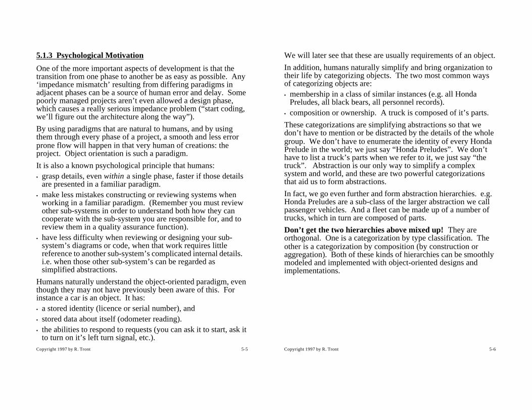
We use the terms ‘object class’ to mean group of instances of things which have the same set of attribute names (e.g. car’s each have a licence number, color, and weight), but which have different values for each of those characteristics (this is what makes the instances of the same class different from each other).
It is common for a class of entity instances to be modelled as a table of fixed length records:
STUDENT TABLE
This concept is in keeping with the view that a student file is a list of fixed length records.
Each column represents an attribute of the type ‘student’ (i.e. a field of a student record). The legal set of values that an attribute may take on is called the domain of the attribute. Examples are date = (1..31), and day= (Sunday..Saturday).
Each row represents a particular instance of a student. Often the rows are sorted in order by a particular column or columns. That column(s) is called the primary key.
You should now review the first part of Appendix A of this section of the course lecture notes, and if taking Cmpt 275 also the second part of Appendix A.
student-id student-name student-address student-phone high-school
93010-1234 Smith, Bill 123 Second St. 420-1234 Mt. Douglas
92010-4321 Jones, Jane 234 Third St. 123-4567 Burnaby
91111-1056 Able, Jim 345 Fourth Rd. 822-9876 John Oliver
Copyright 1997 by R. Tront 5-18
5.4 Object Relationship Diagrams
5.4.1 Object Icons
Let’s examine an example of an Object Relationship Diagram (ORD) carefully. The one below shows two objects.
In is not clear whether they are object instances (since there titles are singular) or entity classes (since only their attribute names and not attribute values are shown). Normally in ORDs it is not really important that you differentiate between whether the boxes are classes or instances. You will probably find it best to think of them as generic instances (not having had attribute values assigned yet). i.e. they are an object storage/record layout plan.
Note that instead of having the attributes listed horizontally, as in the column titles of a table, we have the attributes listed vertically. This is widely done, though there is no reason for this except it makes the entity icons have a smaller maximum dimension. Also, note that the attribute(s) on which the records are sorted are called the primary key of the entity, and are labelled with a ‘*’.
STUDENT HIGH-SCHOOL
* student-id
- student-name
- student-address
- student-phone
- high-school
* high-school
- school-address
- school-phone
Graduated From
Graduated

Copyright 1997 by R. Tront 5-19
5.4.2 Relationships
Object-Relationship Diagrams (ORDs) contain both entity classes and the relationships between them. An example of a relationship is that between a student and a high school.
Fundamentally, relationships are illustrations of links between entities. These links are simply (but importantly) the referential routes that could be traversed by the application code to find other related data. Note that the high school attribute in the student class is a foreign key which provides the information needed to traverse R1. A foreign key is a value- or pointer-based reference to particular related instance (e.g. particular high school). Value-based foreign keys refer to the primary key of the other related (i.e. foreign) object.
ORDs provide a map showing all possible ‘routes’ over which the application can navigate around the data. For instance, given a student object, how does the application code find out what high school she went to? Answer: Look in the High School attribute of that student. Alternately, how does the application code find which students went to a particular high school? Answer: Search the student objects and select all students that went to that particular high school.
You can sometimes during analysis be alerted to a relationship when seeing possessive grammar used. e.g. the student’s high
STUDENT HIGH-SCHOOL
* student-id
- student-name
- student-address
- student-phone
- high-school(R1)
* high-school
- school-address
- school-phone
Graduated From
Graduated
R1
Copyright 1997 by R. Tront 5-20
school, and the high school’s students. Careful though as possessiveness is sometimes just an indicator of an attribute (e.g. Student’s name).
The details of a relationship provide information necessary for the design phase. The details include: • multiplicity, • optionality, • relationship sparseness, and • traversal frequencies.
We will only be concerned with multiplicity and optionality (which together we call cardinality); the others are topics for an advanced course.
A student has graduated from only one high school. But a high school has likely graduated many students. The last sentence is indicative of a 1-to-many (1:M) multiplicity. You will see shortly, that both the multiplicity and optionality of the high school-to-student relationship is important to database design.
The two objects in the ORD are joined by a line indicating the ‘graduated-from/graduated’ relationship. Relationships are always two-way:1) The student Graduated From the high school2) The high school Graduated the student
The relationship phrases are by convention usually put near the end of the relationship line for the direction that version of the relationship name applies.
The ends of the relationship lines have cardinality symbols on them. The symbols closest to the center of the line indicate the optionality as either a 0 or 1. If 0, that means that some students in our database may never have graduated from a high school, and thus don’t have any relationship with a high school. (They may be either mature students let in by special permission, or

Copyright 1997 by R. Tront 5-21
may have finished their high school qualification by attending a college high-school-equivalency program). In that case, the high-school attribute of such a student would be blank or null.
On the other hand, maybe we should insist that all university students first have high school equivalency, and just allow colleges to be listed in the high school file. These policies are called ‘BUSINESS RULES’. As such, the cardinality is determined not from some magic database theory, but from actually asking an application area specialist what the case is: optional (0) or mandatory (1)?
Note that you also have to determine the optionality for the other direction: Is it possible to have a high school in the high school file which has never sent a student to SFU?
You also, through research or interviews have to determine the possible multiplicity for each direction. The multiplicity symbols are located nearest the end of the relationship line. The multiplicity symbol may be either 1 or . The latter symbol is called a “crow’s foot” as it looks like a bird’s foot. It indicates that a high school could have (be related to) more that one student instance. An important database design factor is whether, for a particular (high school) instance at one end of a relationship, there exists multiple related (student) instances of the other object class. This must be determined by the analyst and documented on the ORD.
There are thus 4 combination of optionality and multiplicity for one given end of a relationship line (and 4 for the other end too). They will be shown below.
zero or one one and only one zero or more one or more
Copyright 1997 by R. Tront 5-22
Important note: Just because a relationship is optional or multiple in one direction doesn’t mean it is in the other. The two directions are entirely separate, and must be carefully researched in both directions (what questions would you ask of users?). The fact that an object icon exists on an ORD means that an instance of it can exist. The question is, given its existence, how many instances of another related class of entity can there be that are related to the first?
An important aspect of relationships is that they must be recorded (stored, remembered) somehow. Adding a foreign key is one way.
You should now review Appendix B and C of this section of the course lecture notes on Normalization and Formalization. Your initial identification of the application objects in your system may not have resulted in the best placement of the attributes into objects. This will become immediately apparent as you review Appendices B and C which show the attributes being reorganized into different groupings, and even whole new objects being added to help remember relationships.

Copyright 1997 by R. Tront 5-23
5.5 System BehaviorRecent methodologies suggests that you start analysis by determining an application’s data model first. Even for non-database projects, this identifies early the application domain objects which will most likely form the core software elements (i.e. reactive components) of the eventual implementation. In particular, the names of the important objects, their attributes, and their relationships are researched. Once this is done, we are in a better position to plan the implementation of the behavior of the system.
Previously, programs were regarded as a main module and subprograms which implemented an application’s functionality. The newer, more object-oriented view is that a system’s behavior is simply made up of the sum of the behaviors of the object classes and instances in the system. The objects collaborate together during execution to get each user command done, or handle each significant external event (e.g. network packet arrival).
You can see why we had to identify the core object classes first, as it is they what we now propose to embody with a behavioral nature. But before we start writing code for the system’s objects, we have to decide what behavior each will contribute to the whole. The next question then, is what behavior does each object class and instance need to export to the system, in order that it satisfy it’s behavioral responsibilities to the application? In the next few sub-sections of the lectures, I plan to introduce a very beautiful mechanism to synthesize the required behavior for each object class and instance from the required behavior of the system.
Copyright 1997 by R. Tront 5-24
5.5.1 Event-based Partitioning
Modern applications are event-driven in nature. Think of your personal computer; it idles for billions of instructions waiting for an event like a mouse click, a clock tick, or network packet.
With this view, we will design the system by looking at how each external command or scenario-starting event is handled by the system. By looking at each external command/event one at a time, we can reduce the scope of what we have to think about at any point in the design process to handleable proportions. When writing a requirements specification for a system, it is not uncommon to first list or diagram all the sources of external commands/events that the application must interact with (e.g. keyboard, mouse, clock, network, printer, etc.). Then in more detail, you should name/list each kind of event/command that the application program is to handle from each source.

Copyright 1997 by R. Tront 5-25
5.5.2 External Design (User Manual)
Before beginning architectural design, it should not be uncommon to write a draft user manual to firm up the externally-observable behavior expected of the system for each user command. This sounds weird to some people who feel the manual is written after the coding is done. But you should realize that:• you can’t write the code until everyone on the team knows
what the program is supposed to ‘look like and behave like’! • Often this look and behavior must be approved by someone
else, so rather than spending months first writing a program that is not what the customer wants, you instead spend a week writing a draft version of the user manual for customer pre-approval.
• Many companies do not define a data model or write a draft manual first. But work will seem better organized and often proceed smoother if defining the data model and the proposed behavioral nature of a new application is an early step in the development process.
Copyright 1997 by R. Tront 5-26
5.5.3 Use Case Scenarios
An individual command may have several steps that should be documented in the draft manual. An example sequence might be clicking a menu command, entering several pieces of data in a dialog box, then clicking OK, the application checking and saving the entered data (often different pieces in different objects), then finally telling the user that the command is done and waiting for the user to click OK again. This is called a use case scenario.
Later during architectural design, we must plan what part of each step of a use case scenario will be handled by each different object.
We could thus define:• ‘scenario appearance design’ to be deciding how the progress
of a use case would appear to a user (i.e. write the user manual), and
• ‘scenario call trace design’ (or ‘scenario implementation design’) to be deciding the internal software interactions needed to implement a use case.

Copyright 1997 by R. Tront 5-27
5.6 Object-Oriented Architectural DesignThough there are many aspects to architectural design, we will concentrate here on the design of internal call traces for the scenarios. [Rumbaugh96] states “designing the message flows is the main activity of the design phase of development”.
5.6.1 Object Communication Diagrams (OCD)
It has been common for many years to sketch a diagram indicating which procedures, or more recently which modules, call/communicate/interact with which others. This provides an interaction context which provides further understanding and documentation of the purpose, responsibilities, and dependencies of a module (often one module depends on services provided by another via exported procedures from the other).
Very recently, we have started to diagram object (rather than module) interactions, and thus have named such diagrams Object Communication Diagrams (OCDs) or Object Interaction Diagrams.
Typically, each object class in your ORD which is reactive should be put in your OCD (note: some objects which are simply data records are not reactive and needn’t show in the OCD). You may consider modules which are not C++ objects (e.g. the main program or other utility modules) to also be key reactive components if they export procedures. The primary consideration here is that we identify islands of reactive ability/behavior/intelligence/data/control. These islands, working together, implement the behavior of system.
Note that such a diagram is not to show ‘relationships’, but instead interactions. Two objects which have no relationship could potentially send messages (i.e. call) each other. So an OCD is a somewhat orthogonal view of the objects in a system, and provides a kind of 2nd dimension to their definition.
Copyright 1997 by R. Tront 5-28
The main concept here is to regard and diagram the system as a collection of interacting reactive objects. The arrows show
MAIN
Mid-Level Module#1 #2
ADT A Object C
Mid-Level Module
Object B
User Interface Module

Copyright 1997 by R. Tront 5-29
messages (e.g. procedure calls, sometimes called internal events) moving from one object to another. Receiving objects must be programmed to react appropriately to each message which they receive.
Copyright 1997 by R. Tront 5-30
5.6.2 The Reactive Software Components
There are 5 kinds of reactive software components:1) Function modules like the main and user interface (UI)
library modules (which have static and/or dynamic data).2) Application domain object instances like particular
customers and invoices.3) Application domain object class supervisors (i.e. shepherds),
to be discussed later. 4) Implementation domain object instances like queue and
timer instances5) Implementation domain object class supervisors.
Notice that the first step in identifying the required reactive components needed to build an application was object data analysis. For a small application, if we simply add a main module and a user interface module to the application domain objects, we have an initial set of components which could make up the program.
At program start, the main module is coded to first send start-up messages (i.e. procedure calls) to the important modules telling them to initialize themselves and their subordinates. The main then creates any necessary transient objects, and finally sends a kick-start message to the UI module indicating that it is now OK to start accepting user commands.
So, to begin an Object Communication Diagram (OCD): • First, put a module on the diagram to represent the main
program module. • Then add a icon for each of the objects from your ORD. Do
not draw any of the relationship lines.

Copyright 1997 by R. Tront 5-31
• Next, add a module for each major external interface the system will have. External interfaces are sources of events that drive the system, and exits for output data and control signals. e.g.
- Most systems typically will need a User Interface (UI) module. - Some also include a Network Interface module which would
handle incoming and outgoing network packets. - For systems which control external mechanisms (like robots in a
manufacturing process or a printer), a Process Control module is necessary.
• Finally, you may want to add scenario control/orchestration functions in some module/object of the system.
In the recent non-OO past, it has been suggested for small applications that the main go at the top, the key application abstractions representing objects from your Object Relationship Diagram (ORD) go at the bottom, and some mid-level control modules go in the middle.
• The main module generally is only concerned with initializing things, and shutting them down.
• The low level objects/modules often just provided storage services for different data types.
• The mid-level modules are control/orchestration modules: they control and sequence operations such as getting data one record at a time from a storage object to print a report (storage objects shouldn’t print!). The mid-level modules know which storage object procedures are to be called in which order (possibly in a loop) to accomplish each particular user command (i.e. each use case scenario). The mid-level modules also handle exceptions, such as a storage object rejecting an attempt to read a non-existent record or running out of space to write into.
Copyright 1997 by R. Tront 5-32
If each call arrow in the diagram can be labelled with the message/procedure name it represents, this results in a diagram that shows every name of call that every module/object has to handle! Therefore, a complete and properly-labelled OCD has the information on it to determine every procedure name that needs to be exported by, and then coded in, every module/object.

Copyright 1997 by R. Tront 5-33
5.6.3 Scenario Call Trace Design
In order to determine each reactive component’s responsibilities and the operations it must export, we will examine how each module participates in each use case scenario. In order to reduce the complexity of this design step, we do this one scenario at a time.
In the movie industry, planning for a film segment to be shot is often done on a ‘story board’. The sketches on this board are like a comic book. They provide anticipated camera shots (angles, scenery, costumes) at various moments through the progression of the scene. In essence, the user manual provides sketches of what the application will look like and do, at various points through each scenario. It is a story board. Internal scenario call trace design will also be done using a kind of story board. It is a visual plan and textural explanation of which procedure calls will be made (and why) between which objects at each point during the execution of the scenario.
Note: We could also call this ‘scenario message trace design’, because in the Smalltalk OO language, function calls are termed ‘sending a message’ to another object. Yet other names could be ‘scenario implementation design’, ‘scenario event trace design’, or ‘scenario internal interaction design’.
External events will be the primary driver in our design process. More specifically, a scenario-starting external event is a special kind of external event which initiates a sequence of interactions between the user and the application which carries out a use case scenario as described by the use manual. In menu-driven applications, menu selection events start most use case scenarios. The activation of a menu command results in the application receiving a message from MS-Windows. The user interface component of the application which handles these messages
Copyright 1997 by R. Tront 5-34
subsequently makes procedure calls to other application objects appropriate for the command, and these objects may in turn call other objects or modules.
If the menu command starts a long dialog with the user to enter a number of pieces of data (e.g. customer name, address, phone number) one after the other, the calls may solicit other external events associated with that scenario. These latter events are termed ‘solicited’ as the application subsequently solicits specific further input from the user as is needed to complete the command. The application responds to each solicited event in the appropriate way for that step of the scenario (e.g. read the data, do something with it, prompt for the next entry).
Note: Some methodologies [Shlaer92] consider the calls from one object/module to another to be ‘internal’ events. Each object is then regarded as a finite state machine reacting appropriately to internal events which hit it.

Copyright 1997 by R. Tront 5-35
5.7 Synthesizing Object RequirementsThis subsection looks at a beautiful, step-by-step process by which the requirements for individual reactive components can be obtained from the overall system requirements (as embodied in the use cases).
5.7.1 Step 1 - Generate A Scenario-Starting Event List
From the user manual, generate a list of all scenario-starting external events that are required to be handled by the application. There could be dozens or hundreds in a big system.
5.7.2 Step 2 - Blank Master OCD
An Object Communication Diagram is a diagram which shows the objects from the ORD in a diagram without the relationships, and shows additional reactive components such as main, UI, network interface, and control modules. Generally, the objects are not placed in the same position on the diagram page as they were in the ORD (where they were arranged to make the relationships most tidy). Instead, place the objects in a hierarchical manner radiating away from the principle external event sources (typically the user interface).
(Note: The newer UML notation does not have a master OCD that shows all calls from all use case scenarios. Nonetheless, for an individual scenario, UML does have a so called (object) ‘ Collaboration Diagram’ which is very similar. Collaboration diagrams are just one of two different types of ‘Interaction Diagrams’ offered by UML. Both types are equivalent, but so called ‘Sequence Diagrams’ are portrayed differently. See the “Quick Reference for Rational Rose 4.0 Unified Modelling Language” authored by Rational Corporation in the course pak.
Copyright 1997 by R. Tront 5-36
Main Event Generator(e.g. User Interface)
Senior Object A
Object B Object C
Copyright 1997 by R. Tront 5-37
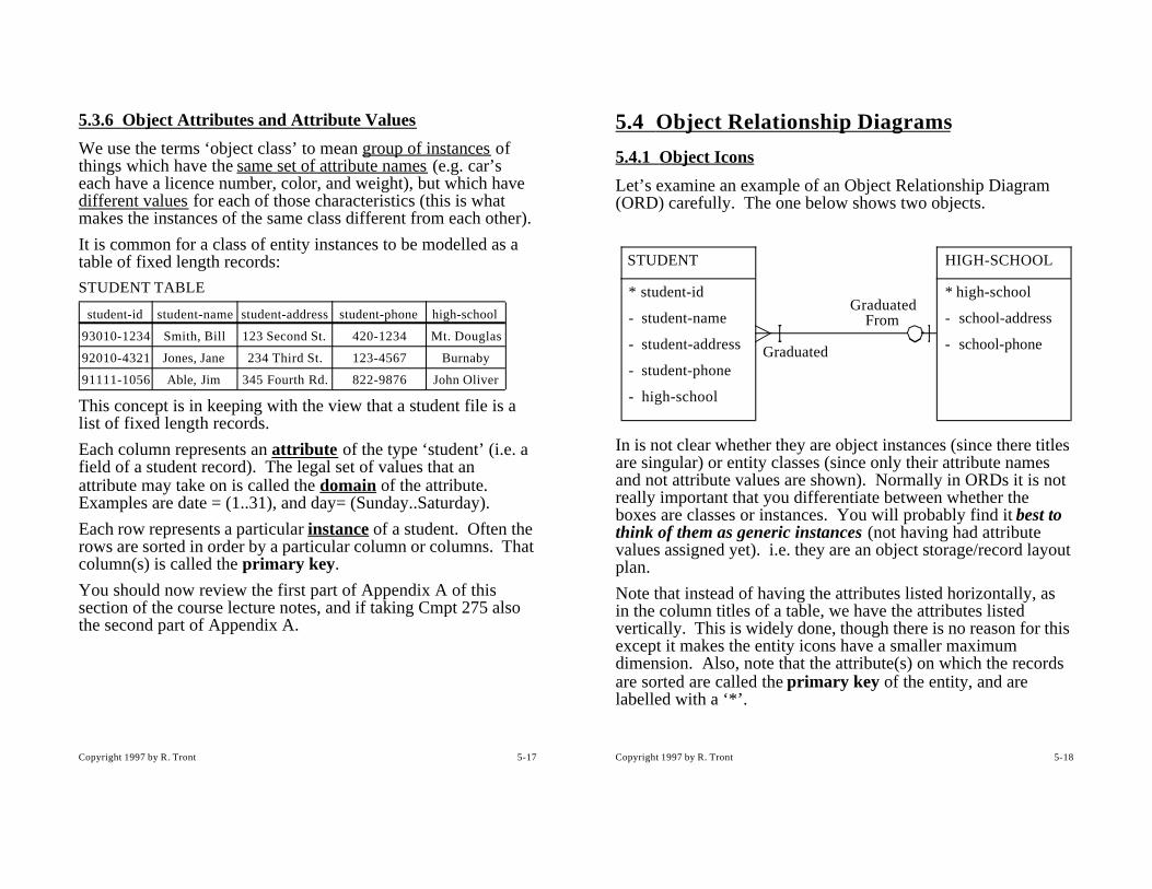
5.7.3 Step 3 - Make an Internal Call Trace for Each Scenario
Make many copies of the blank OCD diagram, one for each scenario-starting external event. For each scenario-starting event, design a trace for the anticipated calls needed to implement the proper response to that external event. (Some of the design issues which impact the choice between different trace options are discussed later). Document the trace on a single, blank OCD page. (By confining ourselves to designing one scenario’s implementation at a time, we need not be distracted by arrows involved in other scenarios).• The first scenario you should consider is the ‘program start’
event. This scenario should be designed to have the main module send a tree of internal initialization events (i.e. calls) to the key objects telling them to initialize (open their files, set stack to empty, etc.). The principle of low coupling dictates that the main module should not know the name of all the objects/modules in the system, but only those directly below it. Those mid-level objects in turn send initialization messages to their subordinate objects. Any of these calls might also create a number of default RAM objects necessary for the initial functioning of the program. Once the system is initialized, the main tells the external event source components (e.g. the user and/or network interfaces) that they can start accepting external events.
Copyright 1997 by R. Tront 5-38
Main Event Generator(e.g. User Interface)
Senior Object A
Object B Object C
4:start_accepting()
1: init_A()
2: init_B() 3: init_C()
Start-up Implementation Call Trace

Copyright 1997 by R. Tront 5-39
Label each message/call with a number indicating it’s sequence in the execution of that scenario, and with the name of the procedure being called.
• On another diagram, for the first external scenario-starting event on your list, draw the trace of calls/messages that will be sent from the external interface object receiving the starting event to the principle reactive objects required to implement the response to that event. This will, in turn, sometimes cause an intermediate control/orchestrator object to send one or more internal messages on to one or more other objects. Give each internal message a sequence number and a name which indicates what procedure is being called (or what the purpose of the message is).Each time you do this, you must think of all the internal object interactions that could take place in handling a particular external event. For instance, to register a student in a course offering, you must first check whether the course offering exists before adding a record to the association object called student-registration.For each diagram, it is usually necessary to document in either a paragraph, list of steps, or pseudo-code, a textural description of how the scenario is planned to be implemented. e.g. “check course exists and has space, then add student to course offering, and update available remaining course space”. This provides reviewers and subsequent implementation programmers with a more understandable idea of how the scenario is to unfold.
Copyright 1997 by R. Tront 5-40
• On a yet another diagram (see next page), do the same for the second user scenario-starting event on your list.
Main Event Generator(e.g. User Interface)
Senior Object A
Object B Object C
User Command #1 Implementation Call Trace
2:UC1()
3:add()
4:enqueue()
1:full?()

Copyright 1997 by R. Tront 5-41
Main Event Generator(e.g. User Interface)
Senior Object A
Object B Object C
User Command #2 Implementation Call Trace
2:UC2()
3:enqueue()
1:full?()
Copyright 1997 by R. Tront 5-42
• On a last diagram, show which module(s) can initiate program shutdown, and the trace/tree of calls to the reactive components which need to be informed of the upcoming shutdown. Such components, upon being notified, shut files, flush buffers, empty tanks, reset the video display mode (e.g. from MS-Windows graphic mode back to DOS text mode, etc.), and delete themselves as appropriate, before the main program ends. (I have not drawn this trace to keep the resulting OCM simple).
Copyright 1997 by R. Tront 5-43
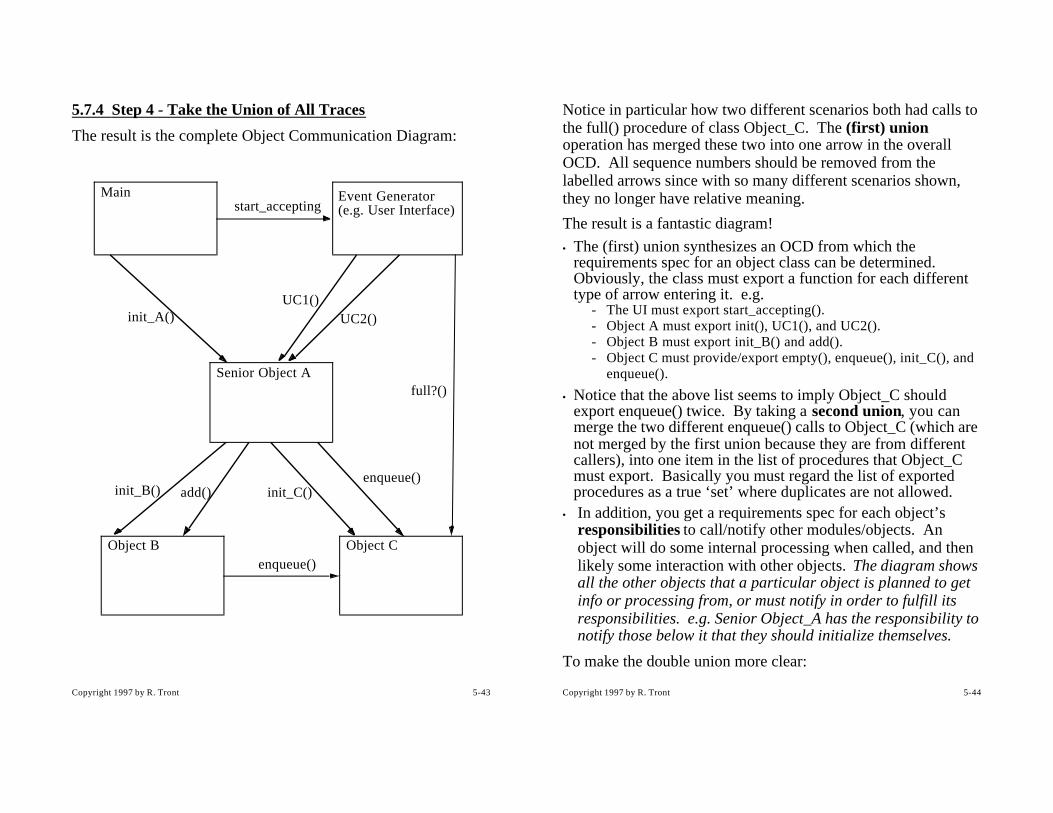
5.7.4 Step 4 - Take the Union of All Traces
The result is the complete Object Communication Diagram:
start_accepting
init_A()
init_B() init_C()
Main Event Generator(e.g. User Interface)
Senior Object A
Object B Object C
UC1()
add()
enqueue()
UC2()
enqueue()
full?()
Copyright 1997 by R. Tront 5-44
Notice in particular how two different scenarios both had calls to the full() procedure of class Object_C. The (first) union operation has merged these two into one arrow in the overall OCD. All sequence numbers should be removed from the labelled arrows since with so many different scenarios shown, they no longer have relative meaning.
The result is a fantastic diagram!
• The (first) union synthesizes an OCD from which the requirements spec for an object class can be determined. Obviously, the class must export a function for each different type of arrow entering it. e.g.
- The UI must export start_accepting().- Object A must export init(), UC1(), and UC2().- Object B must export init_B() and add().- Object C must provide/export empty(), enqueue(), init_C(), and
enqueue().
• Notice that the above list seems to imply Object_C should export enqueue() twice. By taking a second union, you can merge the two different enqueue() calls to Object_C (which are not merged by the first union because they are from different callers), into one item in the list of procedures that Object_C must export. Basically you must regard the list of exported procedures as a true ‘set’ where duplicates are not allowed.
• In addition, you get a requirements spec for each object’s responsibilities to call/notify other modules/objects. An object will do some internal processing when called, and then likely some interaction with other objects. The diagram shows all the other objects that a particular object is planned to get info or processing from, or must notify in order to fulfill its responsibilities. e.g. Senior Object_A has the responsibility to notify those below it that they should initialize themselves.
To make the double union more clear:

Copyright 1997 by R. Tront 5-45
1) The first union constructs the full OCD overlaying all the individual scenario message traces together. Since it is common that the same object could call a certain function in another object in two different scenarios, this first union removes this duplication. This is also why the trace arrow sequence numbers must be removed, since a particular arrow in an OCD can correspond to two or more sequence numbers from different scenarios.
2) The second union is the union of the sets of calls from each other reactive component to (say) object C. If two different other components each call the same function in object C, the second union removes the duplications from the list of functions object C must support. e.g.- set of calls from UI to object C = {full()}- set of calls from A to C = {init_C(), enqueue()}- set of calls from B to C = {enqueue()}The second union is:{full()} + {init_C, enqueue} + {enqueue()} = {full(), init_C(), enqueue()}This resulting list is the set of functions which must be exported via object_c.h and implemented in object_c.cpp!
Obviously the first union does not have to use transparencies, as a CASE tool could automate drawing single scenario traces and then taking the union (I don’t know of any CASE tools that do this yet! I think it would be a great product.). In fact, only one all encompassing union (which accomplishes both partial unions) is needed if the tool doesn’t have to bother creating the OCD for presentation to a software architect.
Copyright 1997 by R. Tront 5-46
5.7.5 Miscellaneous
The above strategy is very powerful as it constructively synthesizes the requirements for individual modules and object classes from an application’s external requirements. This makes it an extremely appropriate technique to bridge the so called ‘design gap’ that exists between the end of analysis and the beginning of writing code for individual modules.
Several methodologies suggest you should design critical scenario architectures individually, using some kind of object ‘interaction’ diagram (and some accompanying descriptive text). But none that I know of suggest that a significant benefit is to be gained by graphically designing them all, then using the double union to synthesize the requirements for every object. I hope you appreciate the beauty of the technique.
This technique could be easily automated. A Computer Aided Software Engineering (CASE) tool could be written which allows you to graphically enter a blank OCD (possibly using objects from your ORD), and then construct scenario traces, one scenario at a time. Finally, a computer is excellent at performing unions to construct the overall OCD, and function prototypes for each object class.
Please note that there are many alternatives in constructing the trace of a scenario. This is where the real design decisions are made. (The diagramming with a CASE tool and the double union are basically just documenting the design decisions and constructively gathering object specifications from the traces). Trace alternatives will be discussed in the next section of the course.
Finally, realize that the arrows you drew represented procedure calls. Data can be passed back to the caller at the end of the call. But not all systems support direct procedure calls. The interaction between different applications, or between different parts of a distributed application, often allow only one way

Copyright 1997 by R. Tront 5-47
messages. In this latter case, return data must be passed back by an additional arrow added to the scenario message diagrams. That is why I have been hesitant, or vague about calling the arrows procedures. In some systems they might not be procedures but one way operating system messages or network packets!
Copyright 1997 by R. Tront 5-48
5.8 Scenario Trace DesignEach and every scenario should be designed with care before you can truly know the system architecture. We will look at three issues to be careful about.
5.8.1 Adding and Designing Non-User Scenarios
Firstly, you have to realize that certain previously un-thought of scenarios may need to be necessary. These scenarios may not even be part of the user scenarios. Good examples are the start-up and shut down scenarios. Those of you familiar with modern languages are aware that they often provide each module or class with an initialization code fragment that is automatically executed at start up. You might not think then that a start up scenario is necessary, that each object or module can be written to automatically initialize itself. Systems can definitely be constructed to this way. But what if a system, while running, needs to do a ‘warm reset’. For example, a user is tired of the situation he has got himself in, and wants to reset everything to its starting condition. Such a system needs a ‘re-start’ scenario.
Also, shut down is necessary for reasons other than just closing files. For instance in a milk processing plant, you might want to shut down the system. This requires telling all tank objects/modules to drain themselves. Even if the main module or user interface detects that the user wants to do a shut down, for reasons of abstraction and design information hiding, the main or UI might not even know that a tank object exists. The shutdown scenario designer is aware of all the objects, and constructs a trace which will get the necessary shutdown control signal down to the tank via a trace of calls. This shutdown trace is constructed to weave down through the abstractions one layer at

Copyright 1997 by R. Tront 5-49
a time since usually each object or module knows only about those immediately below it.
Copyright 1997 by R. Tront 5-50
5.8.2 Labelling Semantic Order
Secondly, in addition to documenting which objects interact with which other objects in a scenario, the numbers on a call event trace document semantic ordering. Sometimes the tree of traces could have several alternative orderings, only one or two of which result in the correct processing of the scenario. If the ordering is not made clear, a implementation programmer who didn’t understand the overall system needs might write the wrong code. For example, given an object which can be both read and written, one scenario might require that the data be written (i.e. initialized) before anything can be read from it. Another scenario might need to read it first (in order to extract and preserve the data) before over-writing it. Numbering the individual calls in a trace documents the ordering you have decided is correct for that particular scenario.
Several methodologists have published various numbering schemes for the individual calls. In most, two calls with the same precedence number indicate that they can be made in either order. In some schemes, using numbers like 2 and 2’ mean that either one or the other message is sent, but not both. Some propose using 2* to indicate repetitive calls. And finally, some assign meaning to decimal numbers (e.g. 2.1, 2.1.3, etc.). These proposals are currently under debate in the OO community, and no common standard currently exists.

Copyright 1997 by R. Tront 5-51
5.8.3 Alternative Control Architectures
Thirdly, as with all design, there are usually several alternate ways to design a sequence of internal call events that will carry out a particular scenario. For example, when the UI receives an ‘exit program’ command from the user, should it send messages to all the objects telling them to shut down? Or should it call a procedure in the main module which should then tell the objects to shut down? ‘Design’ is choosing between workable implementation alternatives to pick the one that is most elegant, most easy to maintain, uses the least memory, and/or is best performing.
Let us consider a simple reservation system. Generally a reservation instance is for a particular flight, sailing, or video rental instance, etc. A reservation typically is related to a particular, say, sailing via a foreign key. When dealing with user-entered data, we must use every effort to maintain referential integrity of the database. Thus before creating a reservation instance for a person on a sailing, we must check that that particular sailing actually exists. This scenario implementation can be designed in one of three alternative ways. These three ways will be shown in the next 3 sub-sub-sections.
Copyright 1997 by R. Tront 5-52
5.8.4 Centralized Scenario Design
In this design, a particular reactive component which both is informed when the scenario is to be initiated, and which understands the scenario to be carried out, orchestrates the execution of the scenario.
Although often not the ideal design, this component may the event detector itself (e.g. user or network interface module), in which case application scenario code (possibly unfortunately) gets added to the UI or network interface module.
Sailing Reservation
1: checkExists() 2: makeReserv()
Detector (e.g. UI) andScenario-Starting Event
Scenario Orchestrator

Copyright 1997 by R. Tront 5-53
Alternatively, as shown below, an extra control module or object can instead be added to house a function which orchestrates a particular scenario. It is not unusual for this module to export more than one function, one in fact for each scenario to be orchestrated in an application (or for a particular subset of scenarios in the application). The external event detector is programmed to simply call the correct scenario orchestration function given the particular scenario-starting event that it just detected.
Sailing Reservation
2: checkExists() 3: makeReserv()
Scenario Description:1) Prompt user for all info;
2) If Sailing exists3) THEN make reservation
4) ELSE re-prompt user.
Event Detector (UI)
1:UC5()
Scenario-Control/Orchestration
Copyright 1997 by R. Tront 5-54
In both the above centralized schemes, the controller sends a message first to the sailing object to check that the sailing exists, then waits for the return from that call, then makes a call to the reservation object (supervisor/shepherd) to actually create the new reservation, the waits for that call to return. The centralized control scheme has the advantage of cohesively encapsulating in one function of one module (be it the Event detector or a special orchestration component) the control and sequencing of internal calls needed to carry out the processing needed in the scenario. Its advantage is that if the control or sequencing of the scenario might later during maintenance need change, only one function in one module needs to be updated. Also notice that the sailing and reservation objects do not communicate with each other, and thus don’t have to know about each other (this is occasionally a good design feature). On the other hand, the central object unfortunately gets coupled to all the parameter types of all the lower calls.
Notice the explanatory text or pseudo-code that can be included under a scenario trace diagram to more fully document the logic of the scenario. This pseudo-code might, for instance, indicate whether the sailing information needed from the user is read by the sailing module or by the central control module.
This pseudo-code may or may not eventually be put into any particular module. It may end up in the central module, or alternatively be spread out over several modules if either of the following designs is adopted. It is therefore not to be thought of as programming, but instead as documentation of the scenario logic from an architect’s point of view, so that programmers could later implement the design properly as per the architect’s plan.
Copyright 1997 by R. Tront 5-55
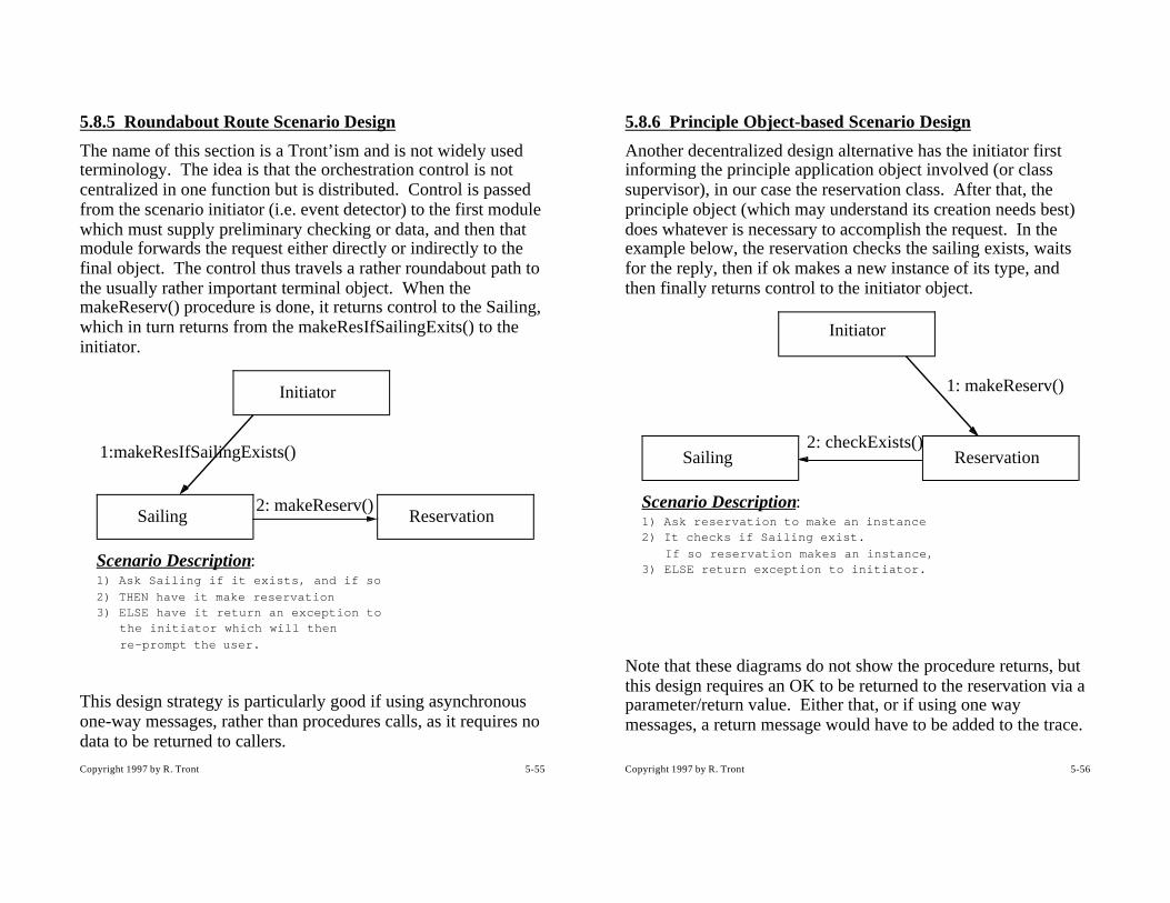
5.8.5 Roundabout Route Scenario Design
The name of this section is a Tront’ism and is not widely used terminology. The idea is that the orchestration control is not centralized in one function but is distributed. Control is passed from the scenario initiator (i.e. event detector) to the first module which must supply preliminary checking or data, and then that module forwards the request either directly or indirectly to the final object. The control thus travels a rather roundabout path to the usually rather important terminal object. When the makeReserv() procedure is done, it returns control to the Sailing, which in turn returns from the makeResIfSailingExits() to the initiator.
This design strategy is particularly good if using asynchronous one-way messages, rather than procedures calls, as it requires no data to be returned to callers.
Sailing Reservation
1:makeResIfSailingExists()
2: makeReserv()
Scenario Description:1) Ask Sailing if it exists, and if so
2) THEN have it make reservation3) ELSE have it return an exception to
the initiator which will then
re-prompt the user.
Initiator
Copyright 1997 by R. Tront 5-56
5.8.6 Principle Object-based Scenario Design
Another decentralized design alternative has the initiator first informing the principle application object involved (or class supervisor), in our case the reservation class. After that, the principle object (which may understand its creation needs best) does whatever is necessary to accomplish the request. In the example below, the reservation checks the sailing exists, waits for the reply, then if ok makes a new instance of its type, and then finally returns control to the initiator object.
Note that these diagrams do not show the procedure returns, but this design requires an OK to be returned to the reservation via a parameter/return value. Either that, or if using one way messages, a return message would have to be added to the trace.
Initiator
Sailing Reservation2: checkExists()
1: makeReserv()
Scenario Description:1) Ask reservation to make an instance2) It checks if Sailing exist.
If so reservation makes an instance,3) ELSE return exception to initiator.
Copyright 1997 by R. Tront 5-57
5.8.7 I/O Library Call Placement
A troubling design question relates to whether all modules/objects should be allowed to call the I/O library, or whether this privilege should be restricted. This is of concern, as one major maintenance headache is the possible future porting of the application to a different operating system or hardware platform (e.g. from MS-Windows to Mac). If you think this is likely, you may want to keep I/O calls confined to be from within a few modules (e.g. somewhat restricting you to centralized control), or within only one module (each object sends its I/O requests to the UI module which is the only one, by architectural policy, allowed to call the OS I/O library). This reduces porting effort as all I/O calls needing changing would be localized to a small number of source modules.
On the other hand, this distributes information about the data types of the attributes of every object needing I/O to the modules allowed to do I/O. It might be better if a student object (which defines the type and length of stud-name, address, phone) do it’s own I/O. That way if a new attribute must be added, or should the length of the address field or type of the phone number field ever need changing, the changes would be restricted to this one object class’s code.
There is no best answer. To port a distributed control application, you could always implement a translation module. Or perhaps C++ provides a good compromise. Define the student phone number type in the student object, overload the output operator for this type, and then let cout<< and cin>> work as they see fit on that type. Unfortunately, now that most UIs are GUI based, you must instead provide ‘convert to ASCII’ member functions for each attribute, and then the phone number (previously an integer) can be displayed via the GUI API.
Copyright 1997 by R. Tront 5-58
5.9 Classes, Instances, and FSMsIn a particularly good OO development methodology [Shlaer92], it is suggested that a excellent way to characterize the behavior of objects is with finite state machines (FSMs). This is because FSMs are perfect to specify the behavior of reactive components such as software modules and objects. This sub-section of the lectures will discuss the last step of the design process, object behavioral design.
5.9.1 Finite State Machines
Finite state machines are a particularly good way to document the required behavior of a reactive component. This is because a FSM is driven by events, and the arrival of an event causes a reaction by the FSM which is appropriate for it’s current state. This is a very common type of behavior needed from software components.
A reactive component’s state is a remembrance of historical context. The state is the current status or mode of the component. Past (i.e. historical) events have caused the component to change into the current mode. For instance, in MS-Windows typing a <shift>-a actually causes 4 event messages to be sent to your program:
1) the <shift> key is pressed.
2) the ‘a’ key is pressed.
3) the ‘a’ key is released.
4) the <shift> key is released.
Normally your winmain() function passes these messages back to Window’s via the keyboard translation procedure.
Message 1 causes the keyboard translation component of MS-Windows to change from the ‘unshifted’ to ‘shifted’ state.
Copyright 1997 by R. Tront 5-59
Message 2 causes the keyboard translation component to tell your program an “A”, not an “a”, has been entered by the user. It does this by first noting (i.e. referring to its memory of past history) that it is in the shifted state. It then performs an action appropriate to that past historical context (e.g. tells your program about the “A”).
Message 3 is ignored. i.e. the keyboard translation component is programmed to causes no action and makes no state change in response to this event.
Message 4 causes no apparent action, but the internal state variable is changed back to ‘unshifted’.
Thus if you worked for Microsoft, and were having to write or document the required behavior of the keyboard translation component of Windows, a FSM would be an idea medium to document this reactive, historically context sensitive behavior!
In fact, many objects that software components model have context sensitive behavior:• You shouldn’t heat a milk tank if it is in the empty state.• You shouldn’t create a diploma if a student hasn’t reached the
graduated state.• You shouldn’t pop from a stack that is empty.• Network connection objects often react to incoming packets in
different ways depending on their current state (e.g. depending on what kind of packet they last sent).
I will elaborate on the stack example to show you the proper way to program context-sensitive, software components.
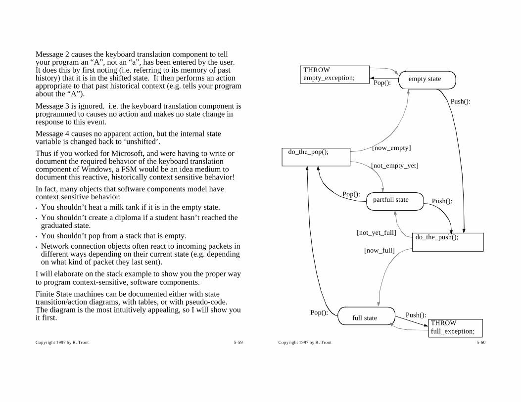
Finite State machines can be documented either with state transition/action diagrams, with tables, or with pseudo-code. The diagram is the most intuitively appealing, so I will show you it first.
Copyright 1997 by R. Tront 5-60
empty state
partfull state
full state
Push():
Pop():
Pop():
Push():
Pop():
[now_full]
[not_yet_full]
[now_empty]
[not_empty_yet]
Push():
THROW empty_exception;
do_the_pop();
do_the_push();
THROW full_exception;
Copyright 1997 by R. Tront 5-61
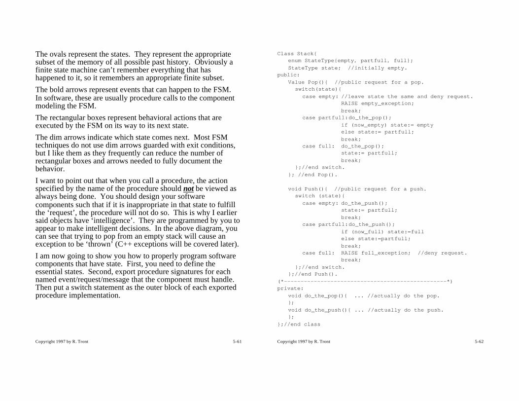
The ovals represent the states. They represent the appropriate subset of the memory of all possible past history. Obviously a finite state machine can’t remember everything that has happened to it, so it remembers an appropriate finite subset.
The bold arrows represent events that can happen to the FSM. In software, these are usually procedure calls to the component modeling the FSM.
The rectangular boxes represent behavioral actions that are executed by the FSM on its way to its next state.
The dim arrows indicate which state comes next. Most FSM techniques do not use dim arrows guarded with exit conditions, but I like them as they frequently can reduce the number of rectangular boxes and arrows needed to fully document the behavior.
I want to point out that when you call a procedure, the action specified by the name of the procedure should not be viewed as always being done. You should design your software components such that if it is inappropriate in that state to fulfill the ‘request’, the procedure will not do so. This is why I earlier said objects have ‘intelligence’. They are programmed by you to appear to make intelligent decisions. In the above diagram, you can see that trying to pop from an empty stack will cause an exception to be ‘thrown’ (C++ exceptions will be covered later).
I am now going to show you how to properly program software components that have state. First, you need to define the essential states. Second, export procedure signatures for each named event/request/message that the component must handle. Then put a switch statement as the outer block of each exported procedure implementation.
Copyright 1997 by R. Tront 5-62
Class Stack{enum StateType{empty, partfull, full};
StateType state; //initially empty.public:
Value Pop(){ //public request for a pop.switch(state){
case empty: //leave state the same and deny request. RAISE empty_exception;
break;case partfull:do_the_pop();
if (now_empty) state:= emptyelse state:= partfull;
break;case full: do_the_pop();
state:= partfull;
break;};//end switch.
}; //end Pop().
void Push(){ //public request for a push.switch (state){
case empty: do_the_push();state:= partfull;
break;case partfull:do_the_push();
if (now_full) state:=fullelse state:=partfull;
break;case full: RAISE full_exception; //deny request.
break;
};//end switch.};//end Push().
(*-------------------------------------------------*)private:
void do_the_pop(){ ... //actually do the pop.};
void do_the_push(){ ... //actually do the push.};
};//end class

Copyright 1997 by R. Tront 5-63
This pseudo-code implements the FSM documented in the previous diagram. You should take a moment to correlate these two different representations of the same FSM.
Note the lovely manner in which each exported function is implemented. Each begins with a switch statement which determines whether the software abstraction will honor the request, given the stack’s current state. The actual pushing and popping is done in non-exported procedures near the bottom of the module. If you write code this organized for most of your life, I will be very proud of you.
One last note. Not all software components are historically context sensitive. If you think your’s is not, you may have overlooked something though; double check your analysis! If you are sure, the component need only model a degenerate event-response machine which has no (or only one) state. The source code layout shown above is not needed, and the class/module can just be written as a collection of exported procedures implementing the requests.
Copyright 1997 by R. Tront 5-64
5.9.2 Class Supervisor and Instances
There are two behavioral parts of a software object class:1) the reactive nature of the class instances.2) the reactive nature of the class supervisor (shepherd).
Though it is not widely suggested, it is essential that you understand the difference between these two separately reactive parts of a class. This is because C++ syntax can blur them and mix you up.
First, you must realize that the behavioral nature of each instance in a class is identical. That’s why they are all in the same class! They all store the same fields of data, and they all have identical behavioral code. What is different about each is that each has different values in their data fields (including different state values). Therefore each may behave differently if sent the same message. For instance, sending a pop message to the night stack may cause a pop, but sending the identical message to the day stack may cause different behavior. This is because each instance might be in a different state.
On the other hand, each class has some supervisory functions that it exports. And this supervisor can have some static variables in which it keeps values relevant to the whole flock of instances. For instance, it might have a count of the number of instances, the average age of the instances, the total $ value of the instances, or a boolean indicating whether one or more instances are currently being used. Notice these are flock attributes! They are items like count, average, total, or boolean attributes of the flock. For this reason, only one copy is needed of each of these ‘supervisor’/‘flock’ variables. In contrast, instance attributes need a field in each instance.
When sending a message to a particular instance, you must specify the ID of the instance you are sending it to. But to send a message to the class supervisor, you specify the name of the

Copyright 1997 by R. Tront 5-65
class (in case different classes both export the same supervisory function name like ‘init()’) and the exact function name.
Since the supervisor’s behavior may be historically context sensitive, it can also be modeled and programmed as a separate finite state machine. And, since it appears as a somewhat different reactive component from the individual instances, you may want to put it as a separate icon on an Object Communication Diagram. Generally, you only put one copy of the instance icon for a class in an OCD, and it is regarded as a generic instance. If one instance sends a message to another instance of the same class, this can be drawn as a loop from the instance icon back to that same instance icon. e.g.
Notice that I have used ovals in this OCD rather than rectangles to indicate that messages are sent between FSMs, not between classes. In the Shlaer-Mellor OO methodology this is sometimes used when you are trying to indicate one rectangular object has two separate state machines (supervisor and instance state machine models), each represented as an oval.
main component UI component
Student Supervisor
Student Instance
Copyright 1997 by R. Tront 5-66
5.10 SummaryWe have taken a good introductory look at object orientation, and at object-oriented data analysis. OOA is nothing new. Information/database systems analysts have been doing it for decades, but it is now realized that it provides a good beginning to decomposing any large system into smaller components. Normalization and formalization help us obtain a clear organization in our head for this data. More recently, instead of regarding this data as passive records, we now encapsulate procedures with them to form the core reactive components of our OO architecture.
Note that it is unclear where analysis ends, and design begins. You must analyze (i.e. obtain through interviews, etc.) the required system behavior as well. This should be listed in the requirements spec. Normally design begins when you have to firm up exactly how the system will look and feel in the draft user manual (i.e. scenario appearance design).
Many software development methodologies lack a definitive process to synthesize/derive the behavioral requirements for programming a particular module from the overall requirements of the application. A key to this derivation is to identify all the use case scenarios that will need to be handled by the application, and to take a few minutes to design the implementation of each one thoughtfully (i.e. scenario implementation design). This is often overlooked by programmers who by their nature seem to want to start coding to early. By enumerating use cases in the requirements spec and in an early written user manual, and the start/reset/shutdown scenarios, we create a list to drive the design process one scenario at a time. The design process becomes the architecting of each scenario implementation with due respect to the various tactical alternatives.
If every scenario trace implementation is planned, a union of the resulting individual scenario implementation designs will

Copyright 1997 by R. Tront 5-67
synthesize the list of exported services that each individual reactive component (object or module) must provide! Then examination for state-dependent behavior and subsequent coding can begin on these individual components.
Unfortunately, you may notice that the design alternatives we have discussed have conflicting advantages (you can’t have everything), and compromises are necessary. Generally you should take the path that will give you the least headaches now, and the least effort later during maintenance (e.g. during later fixing, enhancing, and porting).
Finally, • We saw that finite state machines provide an ideal medium
with which to think about, document, and convey to programmers the behavioral nature of the desired reactive software components. This is because a module/object instance’s behaviour is so often dependent on the previous history of what has happened to it so far during execution (i.e. its response to a particular function call is mode sensitive).
• In addition, finite state machines can be beautifully mapped into a very clear source code using switch/case statement. They thus provide a wonderful guide for the actual code layout.
• And, don’t forget that care must be taken to differentiate between the mode sensitivities of the class supervisor component and of the class instances; they generally are quite different and are thus represented as separate finite state machines.
Copyright 1997 by R. Tront 5-68
5.11 Appendix A - Database OrganizationWe will now overview traditional information systems data modelling, as it provides us with a fantastically logical way to organize our data during the analysis phase of a project.
5.11.1 Why Organize Data Properly?
Information systems, by definition retain persistent data. Persistent data, usually, but not always, mean data retained overnight, between program executions, or over a power shutdown. Integers in RAM memory are also `retained' for shorter times, but the problems of informations systems are usually that of:• storing huge amounts of inter-related data, • for long periods of time, and
being able to rapidly create outputs which have been composed from the retained data, or to be able to easily and rapidly modify particular data records!
Interestingly, learning how to organize persistent data gives us wonderfully clear insights as to how to also organize even our non-persistent (RAM) objects!
Hard disk drives have access times typically in the order of 0.016 seconds (16 ms). Unfortunately, this is still a million times slower (i.e. 6 orders of magnitude) than the instruction time of a 66 MIPS processor! To obtain fast (relative to the processor) random access times requires very special techniques to be used in data bases. Invariably, this requires that retained records in a file all be the same length. That way, to read the 1000th record, you can simply position the read head of the disk drive a distance (999 x Record_Size) from the beginning of the file, and thus avoid reading all the records earlier in the file. It also means that when a record is deleted, then another one added, the added one can fit in the same length space as the one deleted. (If the added record were shorter, some space would be

Copyright 1997 by R. Tront 5-69
wasted. If it was longer, it wouldn't fit and would have to be placed elsewhere and the entire space from the deletion would be wasted until a smaller record needed to be added.)
But not all data records appear to be of fixed length. For instance a student and the courses she is taking this semester:
Student (student-id, semester, {course})
where {} is the Backus-Naur Form (BNF) symbol for zero or more courses. This is called a repeating group by database analysts.
For access performance, we would like to use fixed length disk records, but some students take more courses than others. If say we reserve space for 6 courses for every student, huge amounts of space are wasted if most students only take 5 courses on average.
Properly analyzing the data structure for such an application is done by constructing a data model of the information that needs to be retained, and modifying that model until you get:1) fixed length records.2) no wasted space due to empty or duplicated data.3) fast random and sequential access.4) fast insert and delete operations (not possible with simple
sorted records - why?)
Copyright 1997 by R. Tront 5-70
5.11.2 B+ Trees
This sub-sub-section gives a wonderful introduction to basic database index trees and links.
Generally, characteristics 1) and 2) above are very important tasks of the Analyst. On the other hand, characteristics 3) and 4) are achieved by writing or purchasing database software that uses the Indexed Sequential Access Method (ISAM) which is based on B+ tree index structures on disk. This special kind of tree is very short in height, thus requiring very few disk accesses to traverse down to any randomly-chosen leaf. The tree is always balanced so that no branches are very deep. The use of a tree makes random disk searches, inserts, and deletes as fast as is possible, which is very important as disks are orders of magnitude slower than RAM. Additionally, the leaves are sequentially accessible via a linear, doubly-linked (disk) list. The sequential links make access of the `next' and `previous' items in the sorted structure very fast.
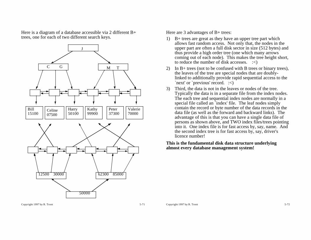
Copyright 1997 by R. Tront 5-71
Here is a diagram of a database accessible via 2 different B+ trees, one for each of two different search keys.
J
C G M T
Bill Celine Harry Kathy Peter Valerie
50000
12500 30000 62300 85000
0750015100 50100 37300 7000099900
Copyright 1997 by R. Tront 5-72
Here are 3 advantages of B+ trees:1) B+ trees are great as they have an upper tree part which
allows fast random access. Not only that, the nodes in the upper part are often a full disk sector in size (512 bytes) and thus provide a high order tree (one which many arrows coming out of each node). This makes the tree height short, to reduce the number of disk accesses. :<)
2) In B+ trees (not to be confused with B trees or binary trees), the leaves of the tree are special nodes that are doubly-linked to additionally provide rapid sequential access to the `next' or `previous' record. :<)
3) Third, the data is not in the leaves or nodes of the tree. Typically the data is in a separate file from the index nodes. The each tree and sequential index nodes are normally in a special file called an `index' file. The leaf nodes simply contain the record or byte number of the data records in the data file (as well as the forward and backward links). The advantage of this is that you can have a single data file of persons as shown above, and TWO index files/trees pointing into it. One index file is for fast access by, say, name. And the second index tree is for fast access by, say, driver's licence number!
This is the fundamental disk data structure underlying almost every database management system!

Copyright 1997 by R. Tront 5-73
5.12 Appendix B - NormalizationThis whole sub-section should give you a good insight into logically re-organizing the data attributes in a application such that the correct attributes are encapsulated together in sensible object classes.
Normalization is a process to modify the data model with the goal of getting fixed length records (for better performance), with little redundancy, and with few optional attribute fields (to save space). Recall that structures in RAM are just fixed length records, too, though it is easier and faster in RAM to have an attribute of a structure point at a linked RAM list to implement the effect of a variable length record. Nonetheless, learning how to implement a system without variable length records will teach you a lot about organizing your data.
In this sub-section I will try to give the rules which define the steps of the process, and illustrate the steps in both a graphical and textural form. I will use the familiar example of a university set of database files, as this will make the learning process easier. But don’t be deceived. In a familiar application, normalization can be done by the analyst almost without thinking because it is based more on common sense than on that weird relational algebra you learn in a database course. On the other hand, in an unfamiliar application area, we don’t have a good sense of what needs to be stored as part of, or related to, other things. Normalization is one important method by which we distill the huge pile of info we get during analysis of an unfamiliar application domain.
Before beginning normalization, you must determine as best you can all the dependencies and cardinalities by asking about the business rules. e.g. Each airliner has a licence number painted on its tail. When storing information about a particular flight, is the flight number or licence number the key? Can a particular plane be used on different flight numbers? Can a flight have many aircraft licence numbers? Maybe, but only on different
Copyright 1997 by R. Tront 5-74
days. So on a given day, the flight is the key, and the licence is the designator attribute which specifies which plane will be used on that flight.
Let’s say our database will need to hold a bunch of info about students, the courses and semesters, and instructors. (This is a good example as it is familiar to you, but a poor example as the relationships and normalizations are easy because are familiar with the application subject area. Remember in real life, you will be asked to analysis unfamiliar subject areas!). Assume the following attributes must be retained about a student.
stud-id
stud-name
address
phone
course
credit
semester
grade
course-room
instructor
instructor-office
We gathered this by interviews, looking at the university calendar, course timetable, telereg instructions, forms, examples of transcripts, and watching the current system in operation.
Repeated for each course taken.
Repeated for each time a particular course is attempted

Copyright 1997 by R. Tront 5-75
In addition to knowing the attributes, we have picked up an understanding of some of the business rules.1) Students take courses.2) Students typically take more than one course in their life.3) Students can fail courses, and can repeat the same course
later in a different semester. Students can thus take the same course more than once.
4) Each time a student takes a course, they are assigned a grade.
Notice I have underlined some nouns and cardinality info. This is a sometimes helpful technique.
Copyright 1997 by R. Tront 5-76
5.12.1 First Normal Form
The above set of attributes are in unnormalized form. They are in unnormalized form as the records needed for different students would NOT all be the same length. This is an unacceptable situation, as it will make fast access and fast insert/deletes impossible, and waste lots of space due to disk fragmentation. The solution is to (unfortunately) add redundancy, by creating a separate row for each occurrence of a student taking a course. (Note: we will later be able to remove this redundancy, but it is a necessary starting step).
CLUE: The data that needs to be retained has repeating groups.
PROCEDURE: Remove repeating groups by adding extra rows to hold the repeated attributes.
FIRST NORMAL FORM: Tables should have no repeating groups.
The result is a single table with a compound (i.e. multi-attribute) primary key.
1NF STUDENT TABLE
Notice that to find a certain row (e.g. find the grade for a particular student in a particular course in a particular semester), you must specify all 3 parts of the primary key. I have also put the 3 attributes that make up the primary key together on the left, and sorted the rows according to the resultant compound key.
student-id course semester grade stud-name
93010-1234 Cmpt 105 95-3 B John Smith
94444-9999 Cmpt 201 95-3 D Bill Jones
94444-9999 Cmpt 201 96-1 C+ Bill Jones

Copyright 1997 by R. Tront 5-77
This in effect creates a single entity class with a large number of attributes:
So now we have fixed length records!
But, there are several problems with this data model:• There is too much redundancy. For instance, if you think of
each entity instance as row in a table, we will be storing both a student’s id, name, address, and phone number each time he enrolls in a course. This is a ridiculous! We need to instead have a separate file of students and the attributes that depend on only the stud-id.
• There are insert anomalies that can occur. It is impossible to admit a student to the university and enter him in this table, unless he has enrolled in a course. This is because the table uses a compound key composed of three different attribute fields. None of these three fields can be null, as they are the data we ask the database access software (ISAM B+ tree) to use in its search. This software would fail if all three parts of the key were not specified.
STUDENT-COURSE* stud-id* course* semester - grade - stud-name - address - phone - course credit - course-room - instructor - instructor-office
Copyright 1997 by R. Tront 5-78
• There are delete anomalies which can occur. If this is the only file which stored which room a course is held in a particular semester, then if you deleted the row containing the only student who had registered in the course so far, you would also delete the only record of which classroom that course will be take place in. This is also ridiculous!
• There are update problems which can occur. Because of all the redundant data, if you wanted to change a woman student’s name because she just got married, you would have to change it in the rows corresponding to every instance of every course she had ever taken! Again this is ridiculous. Though marriage is not that frequent an occurrence for students (compared to the frequency with which they take courses), this is nonetheless a computationally burdensome task. And though many women keep their maiden name these days, the university has to be able to respond to those who do change their names, no matter how many or few occur, because this is provincial law and outside of the university’s jurisdiction to control. So this is a business rule that has been imposed on the university’s business. The analyst must also consider external rules that can be found out from interviews with management, but are not necessarily rules created by management dictate.
Copyright 1997 by R. Tront 5-79
5.12.2 Second Normal Form
CLUE: The problems in the 1st normal form (1NF) organization is that there are non-key attributes which depend on (i.e. are functions of) only part of the compound key. For instance, address is only a function of the stud-id, and credit is only a function of the course, not of the course + student + semester.
PROCEDURE: Remove partial key dependencies. Determine if there are any dependencies of non-key attributes on only part of the compound key. If so, break the first normal form table up into several tables such that in each table, each non-key attribute is dependent on only the primary key of that table.
Note that if the 1NF key is not compound, there cannot be partial key dependencies, and the table will already be in 2NF !
SECOND NORMAL FORM: There are no non-key attributes with partial key dependencies in any table.
For the university application, we ask about the business rules that will tell us something about these dependencies. What we are told is:1) stud-name, address, and phone number are a function of
only the stud-id. Thus we can create a student file of only this information.
2) credit is a function of only the course, and is independent of which semester it is offered in, and which student is taking it. We therefore must separate the concept of a ‘course’ and that of a ‘course offering’ in a particular semester.
3) course-room, course-instructor, and instructor office is a function of only the course and semester, and is independent of which student is taking it.
4) only course grade is necessarily a function of all three parts of the original primary key.
Copyright 1997 by R. Tront 5-80
To get the university application into 2NF, we separate the data into 4 files, each with only the minimal number of attributes needed in each file’s primary key. You will notice that it is a much better organization of the data.

Copyright 1997 by R. Tront 5-81
Second Normal Form ERD:
* stud-id* course* semester - grade
STUDENT-REG
* course* semester - course-room - instructor - instructor-office
COURSE OFFERING
* course - credit
COURSE
* stud-id - stud-name - address - phone
has
is of a
is registered via
is for a
is for a particular
has
many
STUDENT
Copyright 1997 by R. Tront 5-82
That was quite a big leap. We could have first pulled out the stuff that was just dependent only on course and semester. This would have resulted in two entities, student and course. Then we would have still found partial key dependencies in each of those. This is quite common. When you do break a file up, make sure you look again for partial key dependencies in each, as it is often easier to see even more that you might not have noticed in the big original 1NF organization!
Note that in going to 2NF we also had to ask questions about the cardinalities to show on the resultant ORD. These cardinalities did not come from the normalization process; we had to specifically understand or ask about the application domain rules. I have shown reasonable assumptions for the (business) rules regarding cardinality in a university application.
With the data model in 2NF, we can notice the following:• There is now far less redundancy in the organization. Note
that a student’s name doesn’t have to be stored with each of his many registrations, and the course credit needn’t be stored for every course offering.
• a student doesn’t have to be registered in a course for the student to be initially admitted to the university.
• A course, and the room that a course offering will be located in, can be entered even when there are no students registered in that offering yet.
• Most of the update problems have been solved.

Copyright 1997 by R. Tront 5-83
5.12.3 Third Normal Form
There is still problems with the 2NF data model. The course instructor’s office is stored for every occurrence of a course offering. If a professor teaches 4 courses over a year, why do we need to stored his office 4 times. Surely, offices are only a function of the prof’s name, not his name + course teaching assignments! This also causes some remaining insert/delete/update anomalies.
CLUE: The problems in the 2nd normal form (2NF) organization is that there are is an object class with non-key attributes which depend on (i.e. are functions of) other non-key attributes. For instance, instructor-office is a function of the instructor name, and not both of, or either of, course + semester!
PROCEDURE: Remove non-key dependencies. Determine if there are any non-key attributes with dependencies on any other non-key attribute(s). If so, split the table so that the functional dependency is enumerated in its own separate table.
THIRD NORMAL FORM: Every table is in 2NF and additionally, there are no non-key table attributes with dependencies on other non-key attributes (except that dependencies on columns which are also ‘candidate’ keys are allowed; this is a subtle issue covered in database courses).
The one object class in the previous ORD that does have a non-key attribute with a dependency on another non-key, non-candidate-key field is instructor-office. Instructor-office is purely a function of only the instructor’s name. Also note that we can’t move instructor and instructor-office to the course file, as a course can have several instructors teach it over the span of several semesters, or even during one semester. The solution is illustrated on the next diagram.
Copyright 1997 by R. Tront 5-84
Third Normal Form ERD:
* stud-id* course* semester - grade
STUDENT-REG
* course* semester - course-room - instructor
COURSE OFFERING
* course - credit
COURSE
* stud-id - stud-name - address - phone
has
is of a
is registered via
is for a
is for a particular
has
many
STUDENT
* instructor - instructor-office
INSTRUCTOR
has a
instructs a
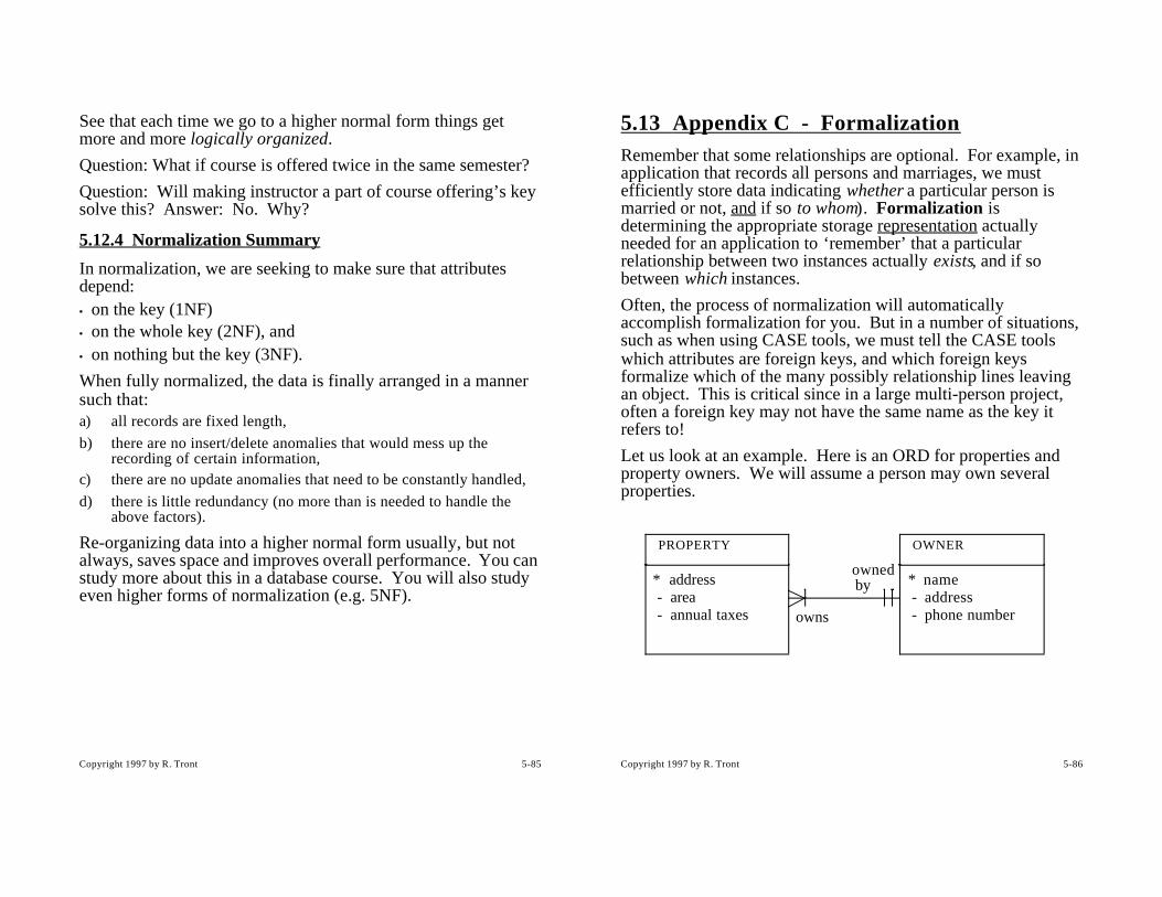
Copyright 1997 by R. Tront 5-85
See that each time we go to a higher normal form things get more and more logically organized.
Question: What if course is offered twice in the same semester?
Question: Will making instructor a part of course offering’s key solve this? Answer: No. Why?
5.12.4 Normalization Summary
In normalization, we are seeking to make sure that attributes depend:• on the key (1NF)• on the whole key (2NF), and• on nothing but the key (3NF).
When fully normalized, the data is finally arranged in a manner such that:a) all records are fixed length,
b) there are no insert/delete anomalies that would mess up the recording of certain information,
c) there are no update anomalies that need to be constantly handled,
d) there is little redundancy (no more than is needed to handle the above factors).
Re-organizing data into a higher normal form usually, but not always, saves space and improves overall performance. You can study more about this in a database course. You will also study even higher forms of normalization (e.g. 5NF).
Copyright 1997 by R. Tront 5-86
5.13 Appendix C - FormalizationRemember that some relationships are optional. For example, in application that records all persons and marriages, we must efficiently store data indicating whether a particular person is married or not, and if so to whom). Formalization is determining the appropriate storage representation actually needed for an application to ‘remember’ that a particular relationship between two instances actually exists, and if so between which instances.
Often, the process of normalization will automatically accomplish formalization for you. But in a number of situations, such as when using CASE tools, we must tell the CASE tools which attributes are foreign keys, and which foreign keys formalize which of the many possibly relationship lines leaving an object. This is critical since in a large multi-person project, often a foreign key may not have the same name as the key it refers to!
Let us look at an example. Here is an ORD for properties and property owners. We will assume a person may own several properties.
* name - address - phone number
OWNER
* address - area - annual taxes
PROPERTY
owns
owned by

Copyright 1997 by R. Tront 5-87
5.13.1 Foreign Keys
This is a nice diagram but does not provide for the storage of the relationships regarding which properties are owned by which owners. This is what is meant by ‘formalization’. The way to formalize most relationships is to add a foreign key to one end of each relationship according to the following rules: • If the multiplicity on one end of the relationship line is many,
and on the other end one, then put the foreign key in the many end.
• If the multiplicity on the two ends of the relationship line is both one, then put the foreign key in the optional end. If both ends are optional, then put the foreign key in either end.
• If the multiplicity on the two ends of the relationship line is both many, the you will need to form a new object called an ‘association’.
In the above case, we use the first rule.
I have added an attribute called “owner” to the ‘many’ end of the above relationship. This attribute, when stored on disk as part of each property entity, records/stores the relationship!
In addition, I have given the relationship a designator (R1), and written this designator beside the foreign key attribute. This is to clear up any misunderstanding that might occur since
* name - address - phone number
OWNER
* address - area - annual taxes - owner (R1)
PROPERTY
owns
owned byR1
Copyright 1997 by R. Tront 5-88
PROPERTY “owner” and the OWNER’s “name” attributes are synonyms. They are two names for the same thing. i.e. the value of an owner foreign key attribute in a PROPERTY entity is the name of the property owner as recorded in the primary key of the OWNER entity. By this I am saying that owner is a reference to that property’s owner’s OWNER record.
Once we have relationships formalized (i.e. stored), we can use them to navigate the ORD to satisfy application operations. e.g. Given the address of a property, I can find the owner’s phone number by:
- first, searching the PROPERTY file for a PROPERTY record whose address attribute value equals the address of the property.
- second, in that record, get the owner’s name by looking at the character string stored in the owner attribute,
- third, look in the PROPERTY_OWNER file for a record whose name = that string.
- finally, look at that PROPERTY_OWNER’s record to get the correct phone number.
This is what I meant earlier when I said that an ORD was a referential map. It shows you all the possible journey directions you can take when referring from one object instance to any related ones.
Note that I can also travel a relationship the other way. Given an owner, I can search the property file for all (i.e. the set of) properties owned by a particular owner.
Note: If we had wrongly added the foreign key to the opposite end of the relationship, the property owner records would then have repeated groups as an owner can own any number of properties. Clearly this leads to variable length records. The best thing is to, as suggested above, add the foreign key to the relationship end with the higher multiplicity.
Here is the student registration system with all the foreign keys identified.

Copyright 1997 by R. Tront 5-89
* stud-id(R1)* course(R2)* semester(R2) - grade
STUDENT-REG
* course(R3)* semester - course-room - instructor(R4)
COURSE OFFERING
* course - credit
COURSE
* stud-id - stud-name - address - phone
has
is of a
is registered via
is for a
is for a particular
has
many
STUDENT
* instructor - instructor-office
INSTRUCTOR
has a
instructs a
R1
R2
R3
R4
Copyright 1997 by R. Tront 5-90
5.13.2 Associations
In what are called ‘many-to-many’ relationships, where the multiplicity is ‘many’ at both ends of the relationship line, adding a foreign key is not enough to formalize the relationship. Instead, a whole new object called an association is needed if you are to keep all records of fixed length.
Continuing with our property registration system, let us now assume that we have recently been told that we have to adjust our system to handle the business rule that a property may be owned by several owners (i.e. partners).
Now a PROPERTY can have several owner attributes (i.e. repeated group, ---> variable length records). In fact there is no way to nicely formalize this simply with a single foreign key. Or with a foreign key in both ends!
We must create a new associative object to store the information about which properties are owned by which and how many owners. (The need for this becomes even more obvious when you consider that you should also store what percentage of each property each owner owns).
* name - address - phone number
OWNER
* address - area - annual taxes - owner (R1)
PROPERTY
owns
owned byR1

Copyright 1997 by R. Tront 5-91
When formalizing a many-to-may relationship with an associative object, the new object will have as a primary key, at least the UNION of the primary keys of the original two objects! This means the primary key of the associative object will be compound! This allows any and all possible pairs of PROPERTY instances and OWNER instances to be recorded via the association.
address owner percentage
123 9th Ave. Smith, Bill 49.5
123 9th Ave. Jones, Jane 50.5
500 First St. Able, Jim 100
999 3rd Ave. Able, Jim 100
* name - address - phone
OWNER
* address - area - annual taxes
PROPERTY
R3* address(R2)* owner (R3) - percentage
LAND TITLE
Refersto
titlerecordedby
R2
has propertytitles
records
Copyright 1997 by R. Tront 5-92
Here we see that such an association can both record the fact that 123 9th Ave. can be owned by two partners, and that Jim Able can own two different properties.
Note: When reading the above ORD, we know the address attribute in the LAND TITLE entity is the address of a property and not of an owner, because the analyst was kind enough to annotate the address attribute to indicate it is a foreign key which formalizes R2. Thus in addition to clarifying some synonym problems, annotating foreign keys can also clarify some homonym problems.
Often the normalization process will generate associative objects automatically for you, as in the university student database (can you find the association?). Other times you may have to do it your self as part of the design phase. And you may have to manually resolve synonym and homonym problems.
Note that an association is might not be an application domain object. It just be a creation of the implementation needed by the application. On the other hand, sometimes it is a physical object in the application domain. An example would be a property deed, which is a legal document stating property ownership.
Finally, the above formalization recommendations may not be optimum (memory or performance-wise) for relationships which are very sparse (not may instances participate in the relationship), or which are traversed during execution very frequently or infrequently. Nonetheless, it is an sound introduction to the concept of formalization.

Copyright 1997 by R. Tront 5-93
5.14 References[Booch98] “The Unified Modelling Language User Guide” by Grady Booch, James Rumbaugh, and Ivar Jacobson, Addison-Wesley, 1998.
[Shlaer 92] “Object Lifecycles: Modelling the World in States” by Sally Shlaer and Stephen Mellor, Prentice-Hall, 1992.
[Rumbaugh96] “To Form A More Perfect Union” by James Rumbaugh in Journal Of Object-Oriented Programming, January 1996, pp. 14-18.