Embed Size (px)
Citation preview
1
April 19, 2023TSPG – 8/16 bit Products Division
MOTOROLA and the Stylized M Logo are registered in the US Patent & Trademark Office. All other product or service names are the property of their respective owners. © Motorola, Inc. 2001.
LIN protocol description
2
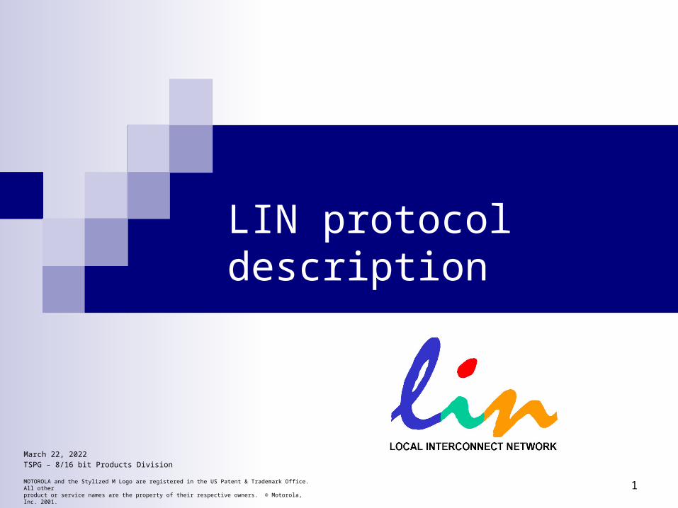
Motorola
LIN Consortium
Daimler-Chrysler
AUDIVW
Volvo
BMW
LINSpec
VCT
Consortium formed in 1998.Five Car manufacturersONE Semiconductor Supplier (Motorola)One tool Supplier (VCT)
LIN targets to low end applications
where the communication cost
per node must be two to three times
lower compared to CAN but
where the performance,
bandwidth, and versatility of
CAN is not required
3
The Need for LIN(a) Multimedia applications, calling for protocols providing high
speed, high bandwidth, and even wireless interconnection, like MOST, D2B, or Bluetooth;
(b) Emerging safety critical applications in chassis and power train (x-by wire) calling for a fault tolerant, dependable protocol,like TTP/C, byteflight, TT-CAN or others;
(c) Conventional body and power train applications, mainly using CAN;
(d) Mechatronic type applications such as smart sensors and actuator, or even complex ECUs with simple communications needs, being addressed by low-end protocols like LIN, TTP/A, J-1850, and quite a few other OEM or Tier-I in-house protocols.
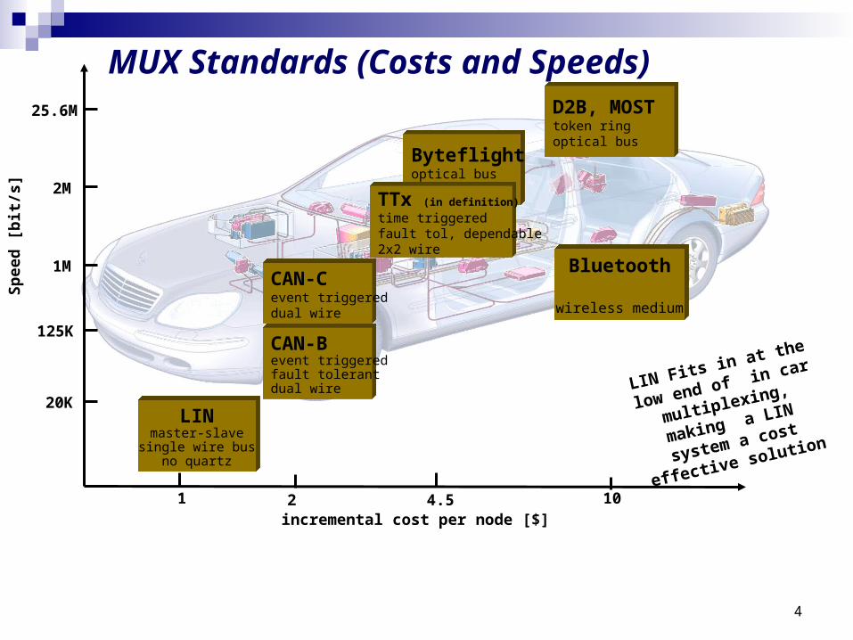
4
MUX Standards (Costs and Speeds)
Spee
d [b
it/s
]
Byteflightoptical bus
LINmaster-slave
single wire busno quartz
CAN-Bevent triggeredfault tolerantdual wire
CAN-Cevent triggereddual wire
TTx (in definition)
time triggeredfault tol, dependable2x2 wire
25.6M
20K
2M
1M
125K
incremental cost per node [$]
D2B, MOSTtoken ringoptical bus
1 2 4.5 10
LIN Fits in at the
low end of in car
multiplexing,
making a LIN
system a cost
effective solution
Bluetooth
wireless medium
5
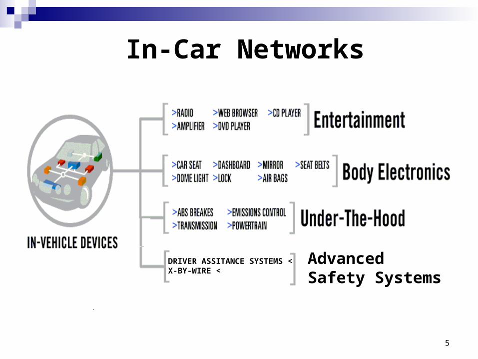
>DRIVER ASSITANCE SYSTEMS >X-BY-WIRE
Advanced Safety Systems
In-Car Networks
6
7
LIN Sub BusW. Specks, H.-C. Wense
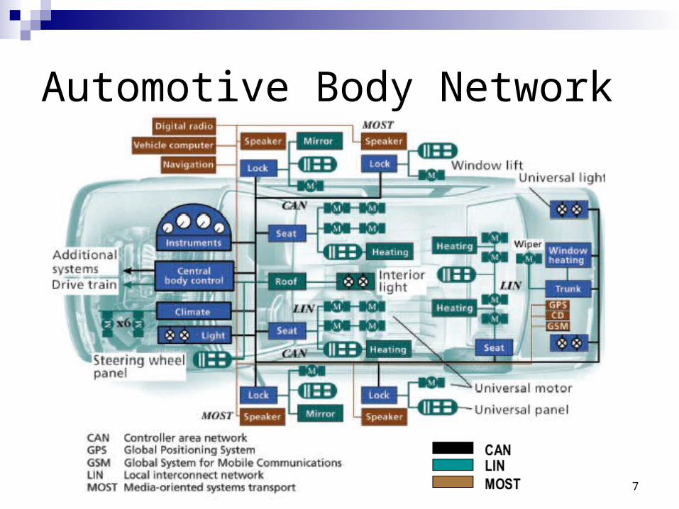
Automotive Body Network
8
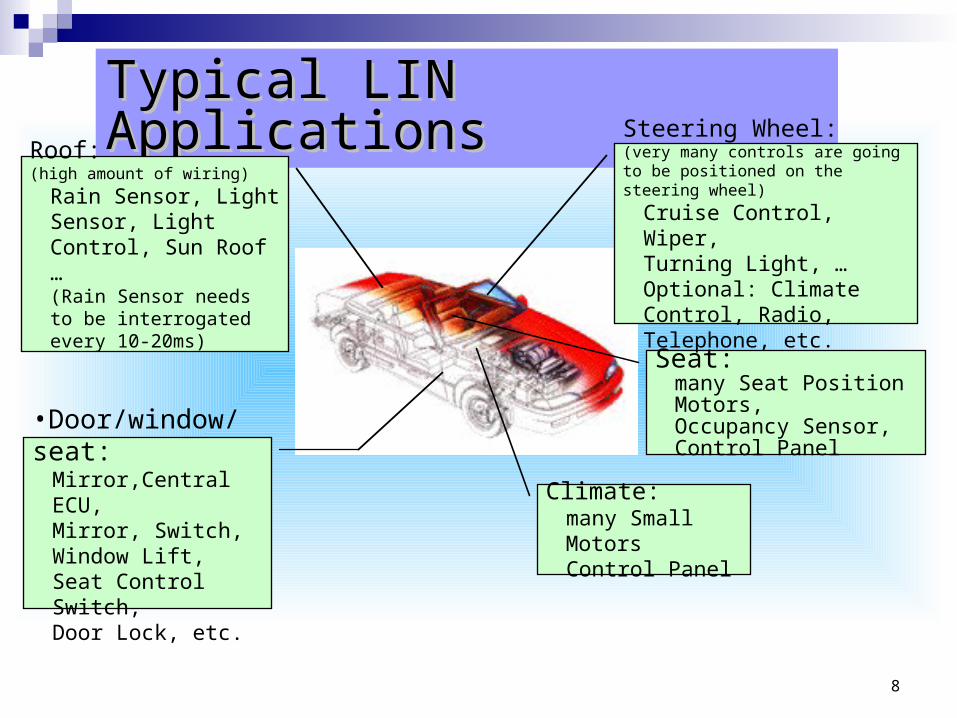
Typical LIN ApplicationsTypical LIN Applications
•Door/window/seat: Mirror,Central ECU, Mirror, Switch, Window Lift,Seat Control Switch,Door Lock, etc.
Roof:(high amount of wiring)
Rain Sensor, Light Sensor, Light Control, Sun Roof …(Rain Sensor needs to be interrogated every 10-20ms)
Seat:many Seat Position Motors,Occupancy Sensor,Control Panel
Steering Wheel:(very many controls are going to be positioned on the steering wheel)
Cruise Control, Wiper,Turning Light, …Optional: Climate Control, Radio, Telephone, etc.
Climate: many Small MotorsControl Panel
10
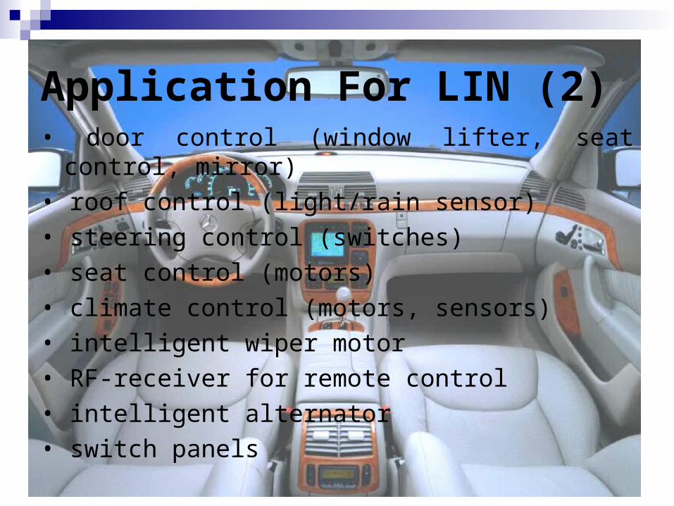
Application For LIN (2)• door control (window lifter, seat control, mirror)
• roof control (light/rain sensor)
• steering control (switches)
• seat control (motors)
• climate control (motors, sensors)
• intelligent wiper motor
• RF-receiver for remote control
• intelligent alternator
• switch panels
11
14
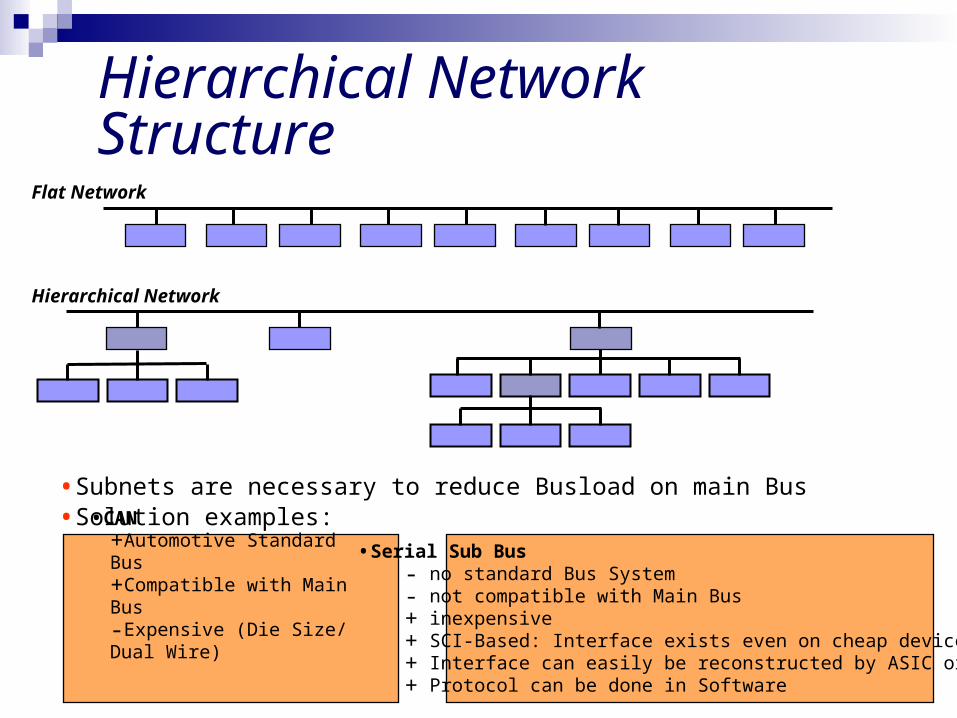
Hierarchical Network StructureFlat Network
•CAN+Automotive Standard Bus+Compatible with Main Bus-Expensive (Die Size/ Dual Wire)
Hierarchical Network
• Subnets are necessary to reduce Busload on main Bus• Solution examples:
•Serial Sub Bus- no standard Bus System- not compatible with Main Bus+ inexpensive+ SCI-Based: Interface exists even on cheap devices+ Interface can easily be reconstructed by ASIC or CPLD+ Protocol can be done in Software
15
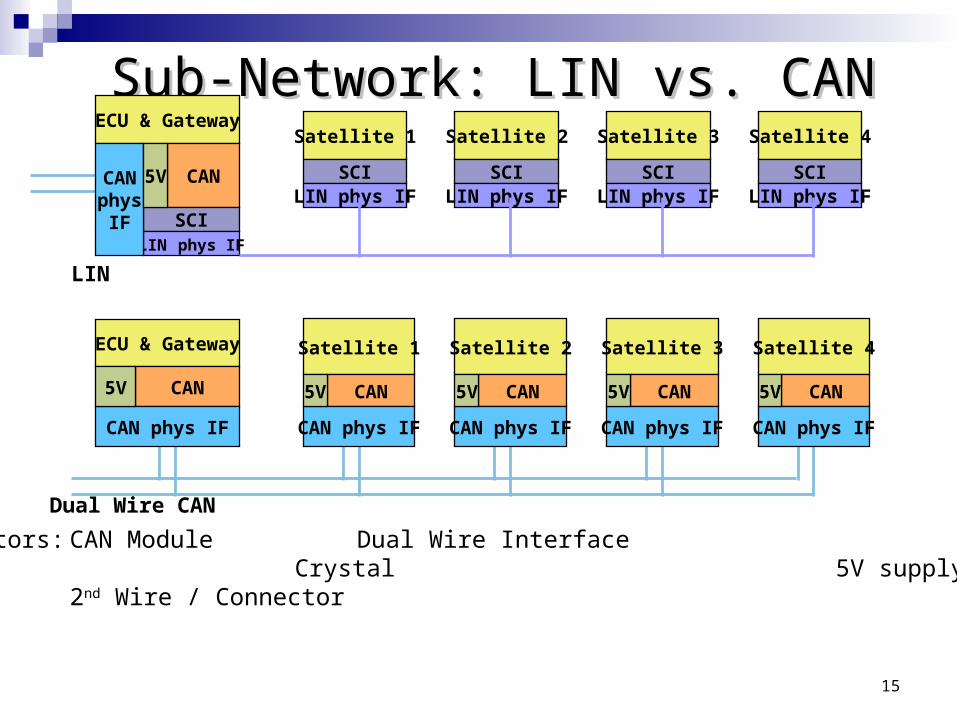
Sub-Network: LIN vs. CANSub-Network: LIN vs. CANECU & Gateway
CAN
SCI
Satellite 1
SCI
Satellite 2
LIN phys IFSCI
LIN phys IF
Satellite 3
SCILIN phys IF
Satellite 4
SCILIN phys IF
LIN phys IF
ECU & Gateway
CAN
Satellite 1 Satellite 2 Satellite 3 Satellite 4
CAN CAN CAN CAN
LIN
Dual Wire CAN
Cost Factors: CAN Module Dual Wire Interface Crystal 5V supply for bus 2nd Wire / Connector
CAN phys IF CAN phys IF CAN phys IF CAN phys IF CAN phys IF
CANphys
IF
5V 5V 5V 5V 5V
5V
16
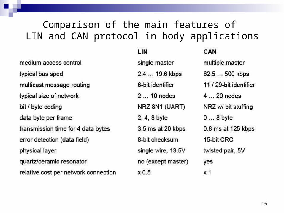
Comparison of the main features of LIN and CAN protocol in body applications
17
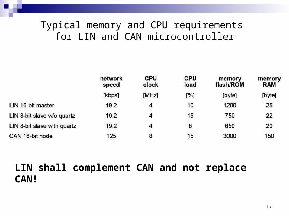
Typical memory and CPU requirements for LIN and CAN microcontroller
LIN shall complement CAN and not replace CAN!
19
Sub Bus Concept
Basic Requirements: Satisfy Need for a Standard for Sub Busses Cost driven: The solution must be cheaper than CAN Reliability: Same Level as CAN expected Long Term Solution Logical Extension to CAN Scalable: Capability to extend Systems with additional nodes Lowering Cost of Satellite nodes:
No Crystal or Resonator Easy implementation Simple State Machines
Low Reaction Time (100 ms max) Predictable Worst Case Timing
20
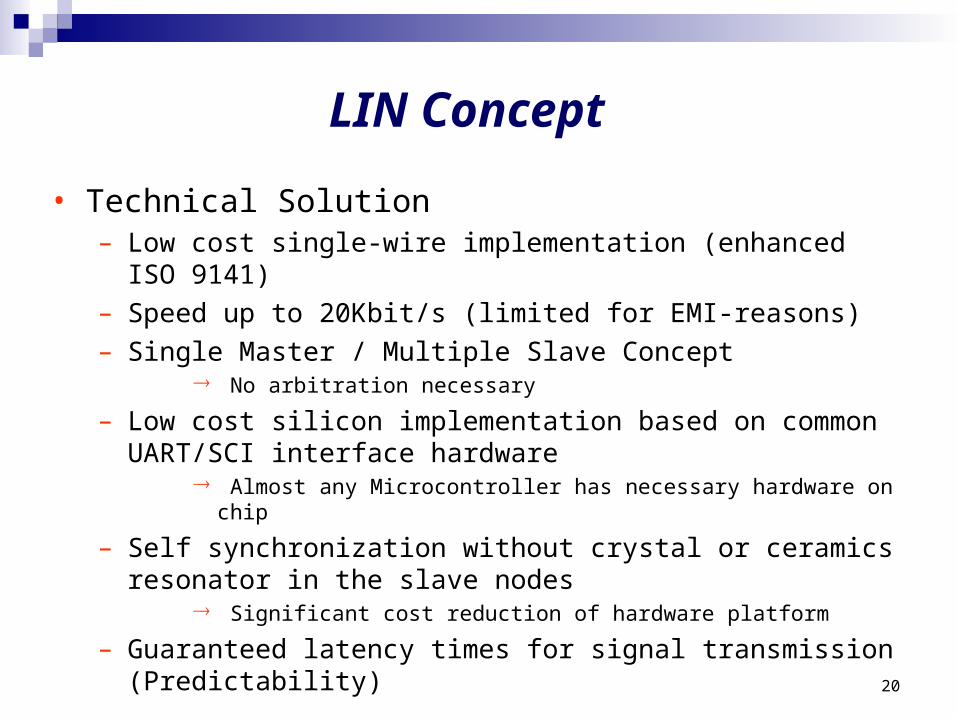
LIN Concept
• Technical Solution– Low cost single-wire implementation (enhanced ISO 9141)– Speed up to 20Kbit/s (limited for EMI-reasons)– Single Master / Multiple Slave Concept
No arbitration necessary
– Low cost silicon implementation based on common UART/SCI interface hardware
Almost any Microcontroller has necessary hardware on chip
– Self synchronization without crystal or ceramics resonator in the slave nodes
Significant cost reduction of hardware platform
– Guaranteed latency times for signal transmission(Predictability)
21
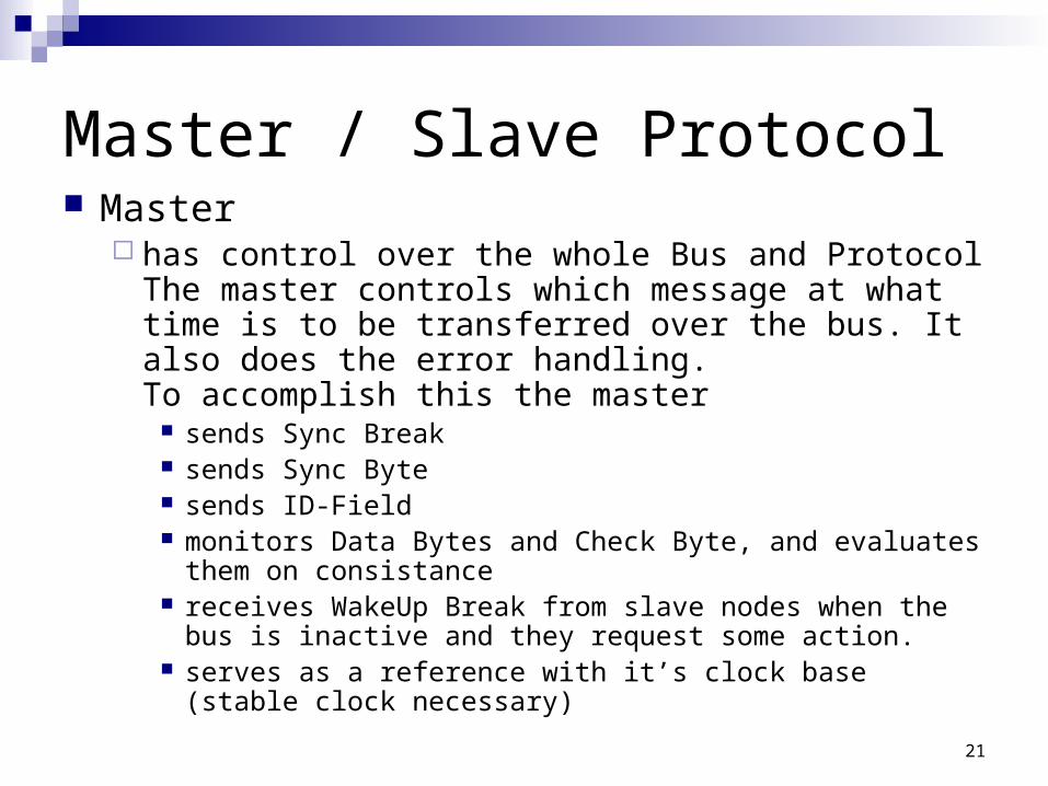
Master / Slave Protocol Master
has control over the whole Bus and ProtocolThe master controls which message at what time is to be transferred over the bus. It also does the error handling. To accomplish this the master
sends Sync Break sends Sync Byte sends ID-Field monitors Data Bytes and Check Byte, and evaluates them on
consistance receives WakeUp Break from slave nodes when the bus is
inactive and they request some action. serves as a reference with it’s clock base (stable clock
necessary)
22
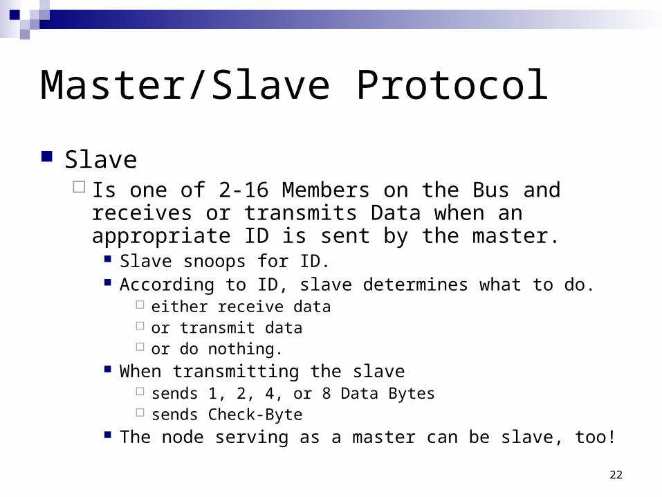
Master/Slave Protocol
Slave Is one of 2-16 Members on the Bus and receives or
transmits Data when an appropriate ID is sent by the master.
Slave snoops for ID. According to ID, slave determines what to do.
either receive data or transmit data or do nothing.
When transmitting the slave sends 1, 2, 4, or 8 Data Bytes sends Check-Byte
The node serving as a master can be slave, too!
24
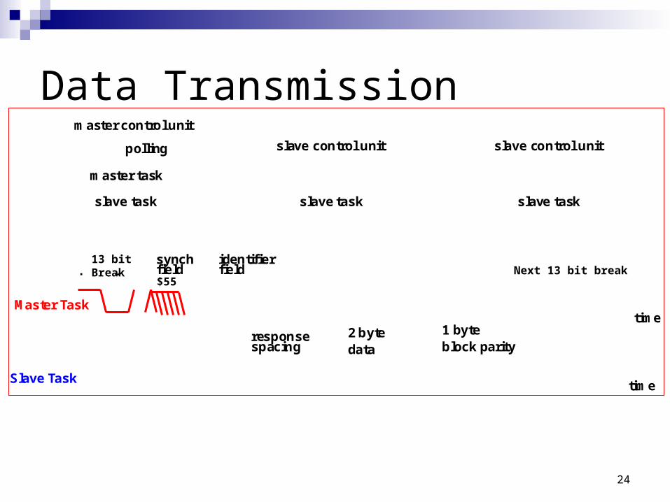
Data Transmission
timeMaster Task
timeSlave Task
next synch fieldinter-framespacing
synchfield
2 byte 1 byteresponse spacing
identifierfield
block paritydata
master control unit
slave task
master task
slave control unit
slave task
slave control unit
slave task
polling
13 bitBreak
$55Next 13 bit break
25
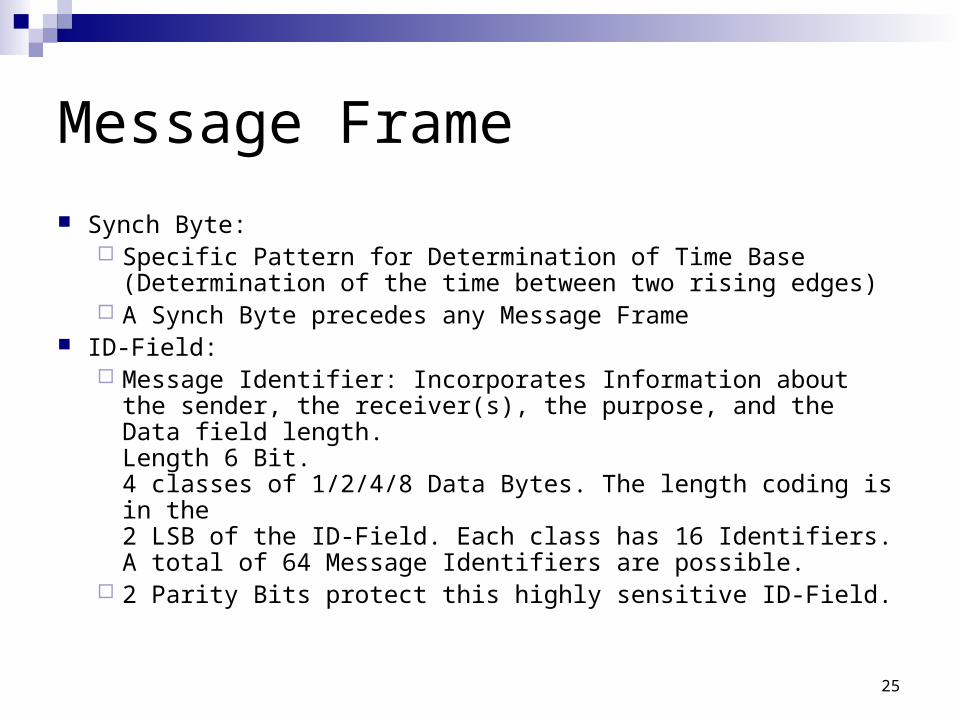
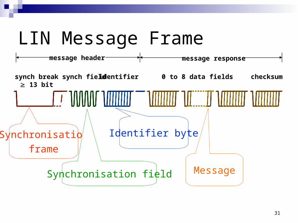
Message Frame
Synch Byte: Specific Pattern for Determination of Time Base
(Determination of the time between two rising edges) A Synch Byte precedes any Message Frame
ID-Field: Message Identifier: Incorporates Information about the
sender, the receiver(s), the purpose, and the Data field length.Length 6 Bit. 4 classes of 1/2/4/8 Data Bytes. The length coding is in the 2 LSB of the ID-Field. Each class has 16 Identifiers. A total of 64 Message Identifiers are possible.
2 Parity Bits protect this highly sensitive ID-Field.
26
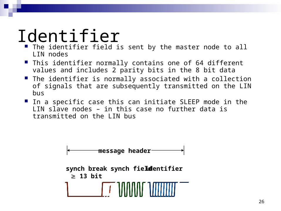
Identifier The identifier field is sent by the master node to all LIN nodes This identifier normally contains one of 64 different values
and includes 2 parity bits in the 8 bit data The identifier is normally associated with a collection of
signals that are subsequently transmitted on the LIN bus In a specific case this can initiate SLEEP mode in the LIN
slave nodes – in this case no further data is transmitted on the LIN bus
synch break 13 bit
synch field identifier
message header
27
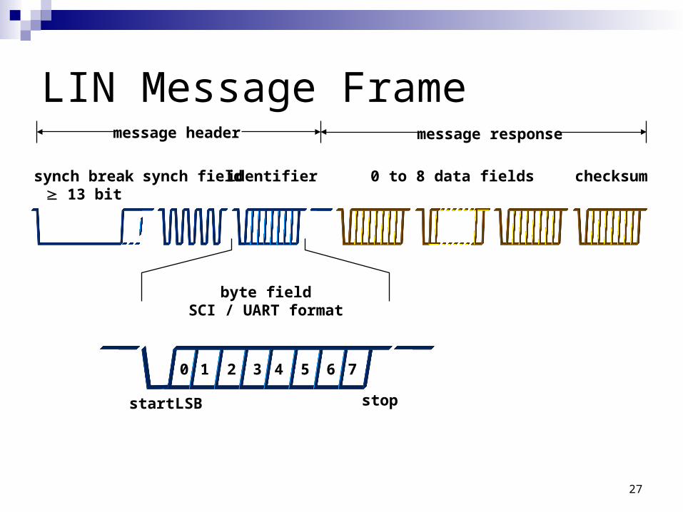
LIN Message Frame
0 to 8 data fields checksum
message response
synch break 13 bit
synch field identifier
message header
byte fieldSCI / UART format
start stop
0 1 2 3 4 5 6 7
LSB
28
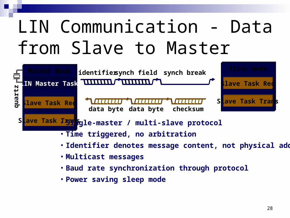
LIN Communication - Data from Slave to Master
data byte data byte checksum
synch field identifier synch break Slave Node
Slave Task Trans
Slave Task Rec
Master Node
LIN Master Task
Slave Task Trans
Slave Task Recqu
artz
• Single-master / multi-slave protocol
• Time triggered, no arbitration
• Identifier denotes message content, not physical address
• Multicast messages
• Baud rate synchronization through protocol
• Power saving sleep mode
29
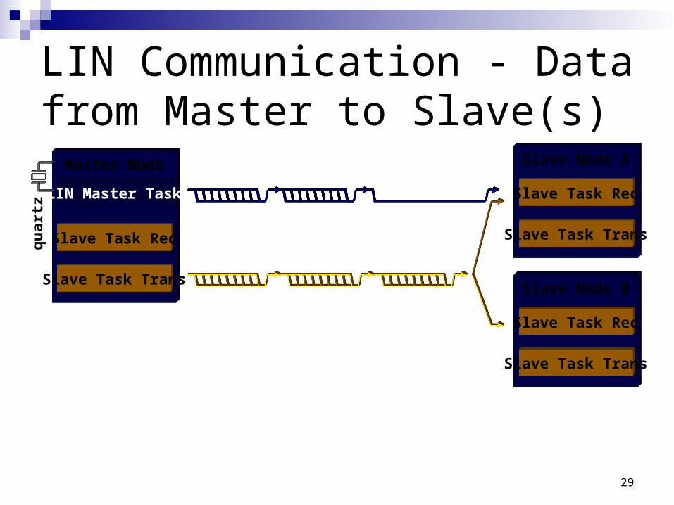
LIN Communication - Data from Master to Slave(s)
Master Node
LIN Master Task
Slave Task Trans
Slave Task Recqu
artz
Slave Node A
Slave Task Trans
Slave Task Rec
Slave Node B
Slave Task Trans
Slave Task Rec
30
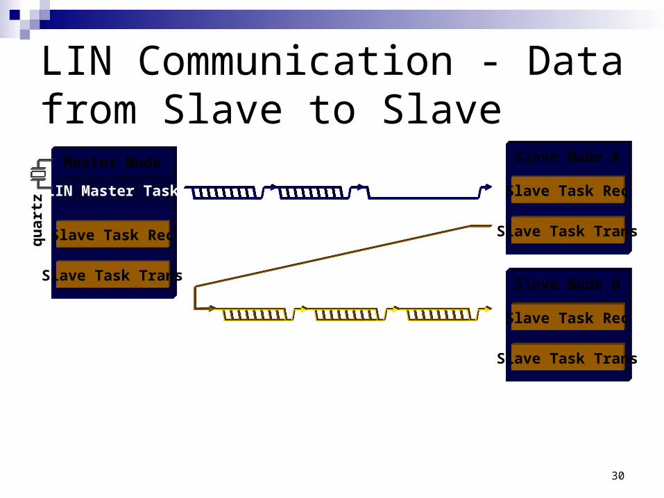
LIN Communication - Data from Slave to Slave
Slave Node A
Slave Task Trans
Slave Task Rec
Slave Node B
Slave Task Trans
Slave Task Rec
Master Node
LIN Master Task
Slave Task Trans
Slave Task Recqu
artz
31
LIN Message Frame
0 to 8 data fields checksum
message response
synch break 13 bit
synch field identifier
message header
Synchronisation
frame
Synchronisation field
Identifier byte
Message
32
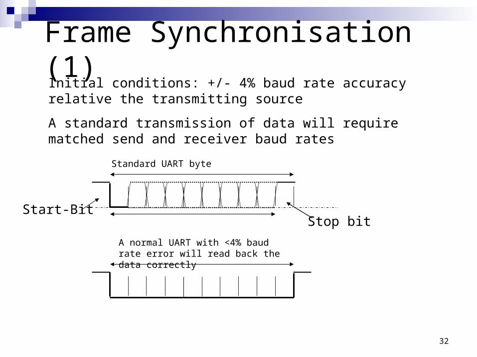
Frame Synchronisation (1)Initial conditions: +/- 4% baud rate accuracy relative the transmitting source
A standard transmission of data will require matched send and receiver baud rates
Stop bitStart-Bit
Standard UART byte
A normal UART with <4% baud rate error will read back the data correctly
33
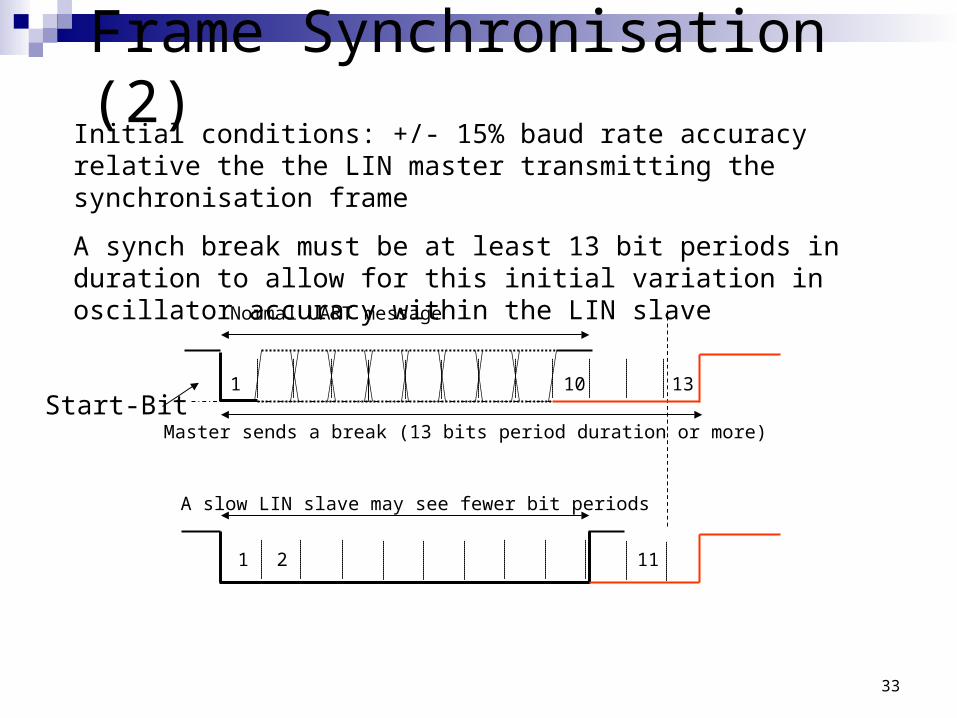
Frame Synchronisation (2)Initial conditions: +/- 15% baud rate accuracy relative the the LIN master transmitting the synchronisation frame
A synch break must be at least 13 bit periods in duration to allow for this initial variation in oscillator accuracy within the LIN slave
Start-Bit
Normal UART message
Master sends a break (13 bits period duration or more)
A slow LIN slave may see fewer bit periods
1 2 11
1 10 13
34
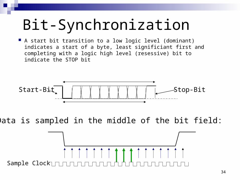
Bit-Synchronization A start bit transition to a low logic level (dominant) indicates
a start of a byte, least significiant first and completing with a logic high level (resessive) bit to indicate the STOP bit
Stop-BitStart-Bit
Data is sampled in the middle of the bit field:
Sample Clock
35
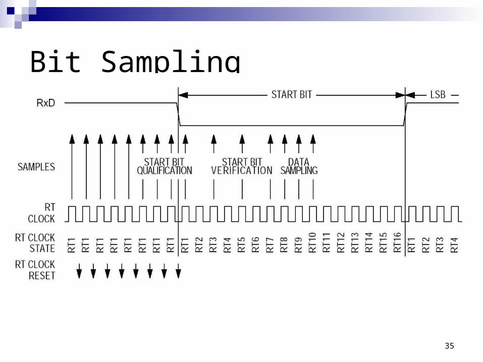
Bit Sampling
36
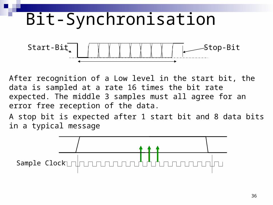
Bit-Synchronisation
Stop-BitStart-Bit
Sample Clock
After recognition of a Low level in the start bit, the data is sampled at a rate 16 times the bit rate expected. The middle 3 samples must all agree for an error free reception of the data.
A stop bit is expected after 1 start bit and 8 data bits in a typical message
37
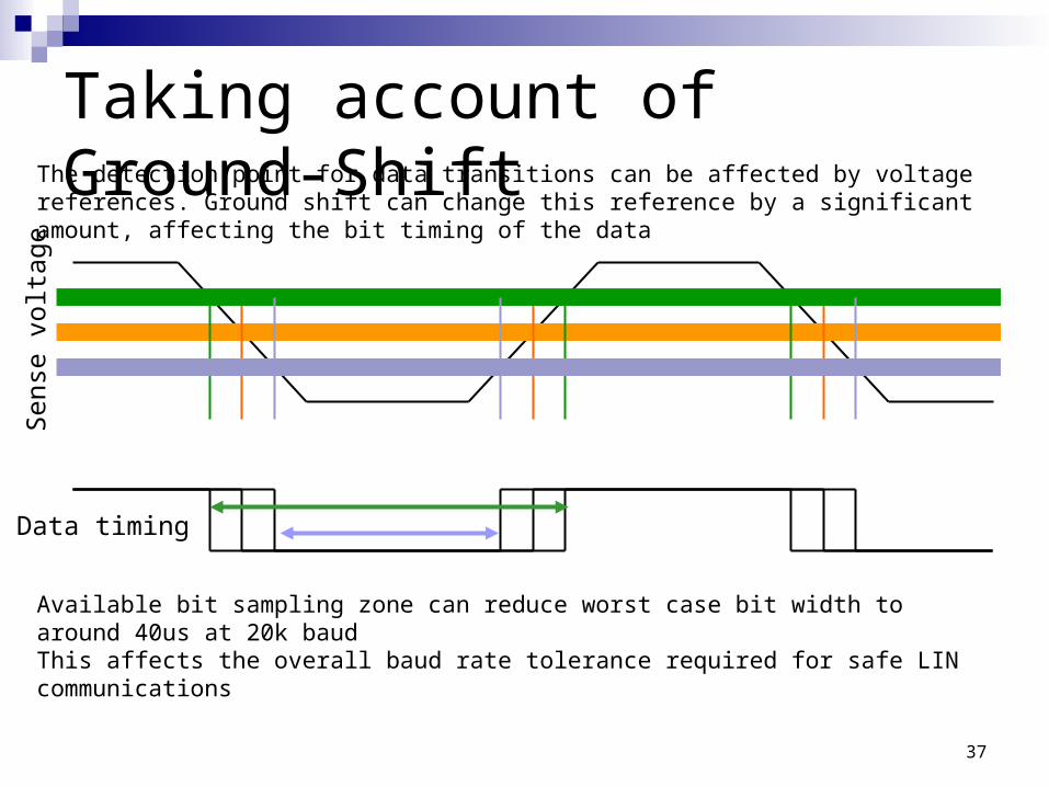
Taking account of Ground-ShiftThe detection point for data transitions can be affected by voltage references. Ground shift can change this reference by a significant amount, affecting the bit timing of the data
Data timing
Sen
se v
olta
ge
Available bit sampling zone can reduce worst case bit width to around 40us at 20k baudThis affects the overall baud rate tolerance required for safe LIN communications
38
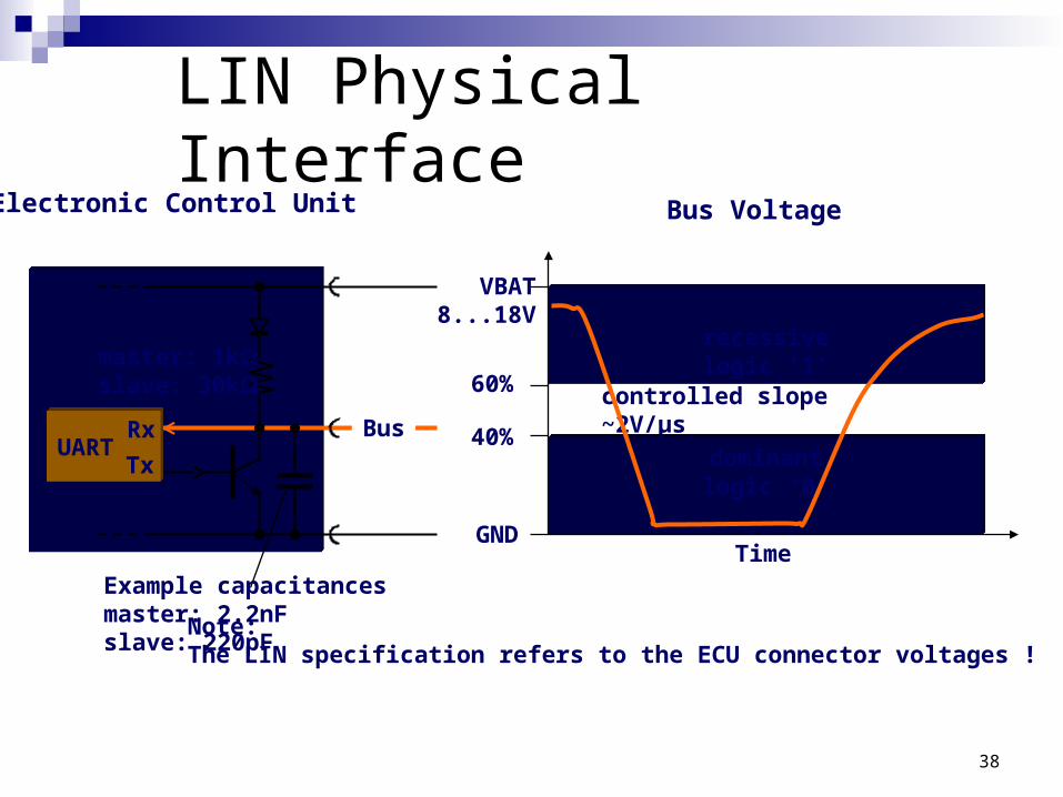
LIN Physical Interface
VBAT8...18V
GND
recessivelogic ‘1’
dominantlogic ‘0’
60%
40%
Bus Voltage
Time
UARTRx
Tx
Electronic Control Unit
master: 1kslave: 30k
Buscontrolled slope~2V/µs
Example capacitancesmaster: 2.2nFslave: 220pF
Note: The LIN specification refers to the ECU connector voltages !
40
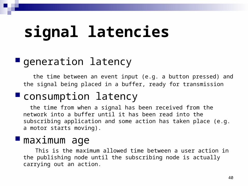
signal latencies
generation latency the time between an event input (e.g. a button pressed) and the signal being
placed in a buffer, ready for transmission
consumption latency the time from when a signal has been received from the network into a buffer
until it has been read into the subscribing application and some action has taken place (e.g. a motor starts moving).
maximum age This is the maximum allowed time between a user action in the publishing
node until the subscribing node is actually carrying out an action.
41
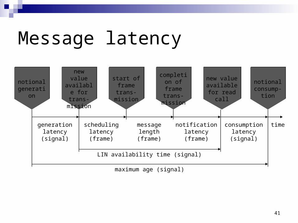
Message latency
new value available for
read call
completion of frame
trans-mission
start of frame trans-
mission
new value available for trans-mission
notionalgeneration
generationlatency(signal)
notionalconsump-
tion
timeconsumptionlatency(signal)
messagelength(frame)
schedulinglatency(frame)
notificationlatency(frame)
LIN availability time (signal)
maximum age (signal)
42
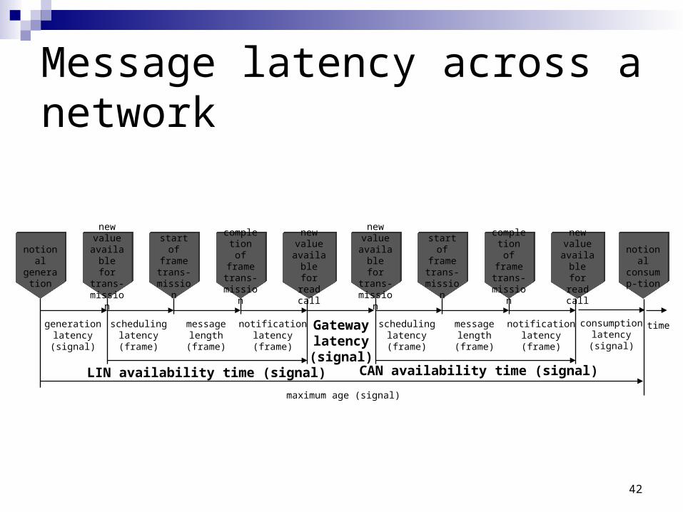
Message latency across a network
notionalgenerati
on
new value
available for
trans-mission
new value
available for read
call
start of frame trans-
mission
completion of frame trans-
mission
generationlatency(signal)
timeconsumptionlatency(signal)
messagelength(frame)
schedulinglatency(frame)
notificationlatency(frame)
LIN availability time (signal)
maximum age (signal)
new value
available for
trans-mission
new value
available for read
call
start of frame trans-
mission
completion of frame trans-
mission
messagelength(frame)
schedulinglatency(frame)
notificationlatency(frame)
Gatewaylatency(signal)
CAN availability time (signal)
notionalconsump-tion
43
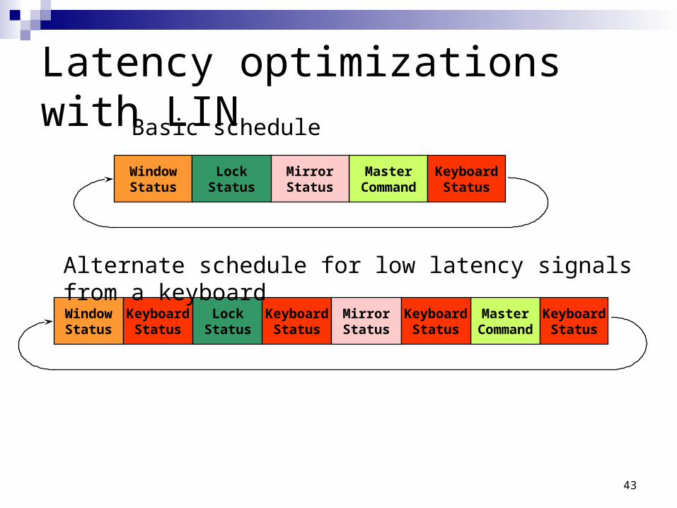
Latency optimizations with LIN
WindowStatus
MasterCommand
MirrorStatus
LockStatus
KeyboardStatus
WindowStatus
LockStatus
KeyboardStatus
MasterCommand
MirrorStatus
KeyboardStatus
KeyboardStatus
KeyboardStatus
Basic schedule
Alternate schedule for low latency signals from a keyboard
44
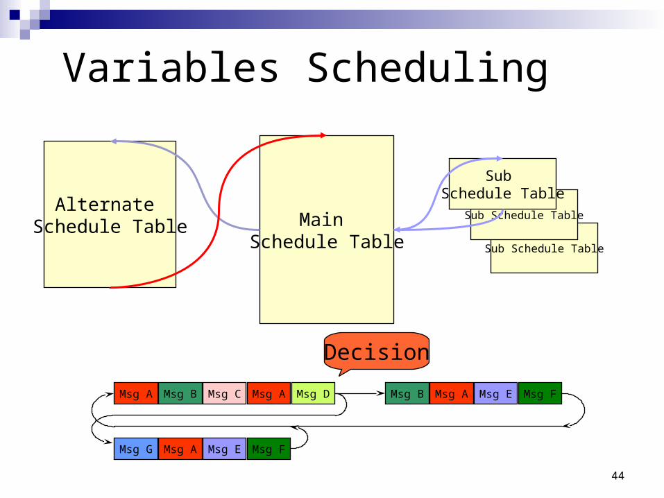
Sub Schedule Table
Variables Scheduling
Main Schedule Table
Sub Schedule Table
Sub Schedule Table
Alternate Schedule Table
Msg A Msg EMsg AMsg DMsg AMsg CMsg B Msg B Msg F
Decision
Msg EMsg AMsg G Msg F
45
Event Triggered Message Problem
Specific node communication required but this takes up too much time for all network messages
Solution : Event Triggered frame: Header is sent out
1. normal case: no answer 2. Rare response: only one node responds 3. Very rare response : several nodes respond simultaneously
Cases 1 and 3 are exceptions that should be addressed at the application design.
Event triggered messaging is complementary to the regular signal based messaging scheme
46
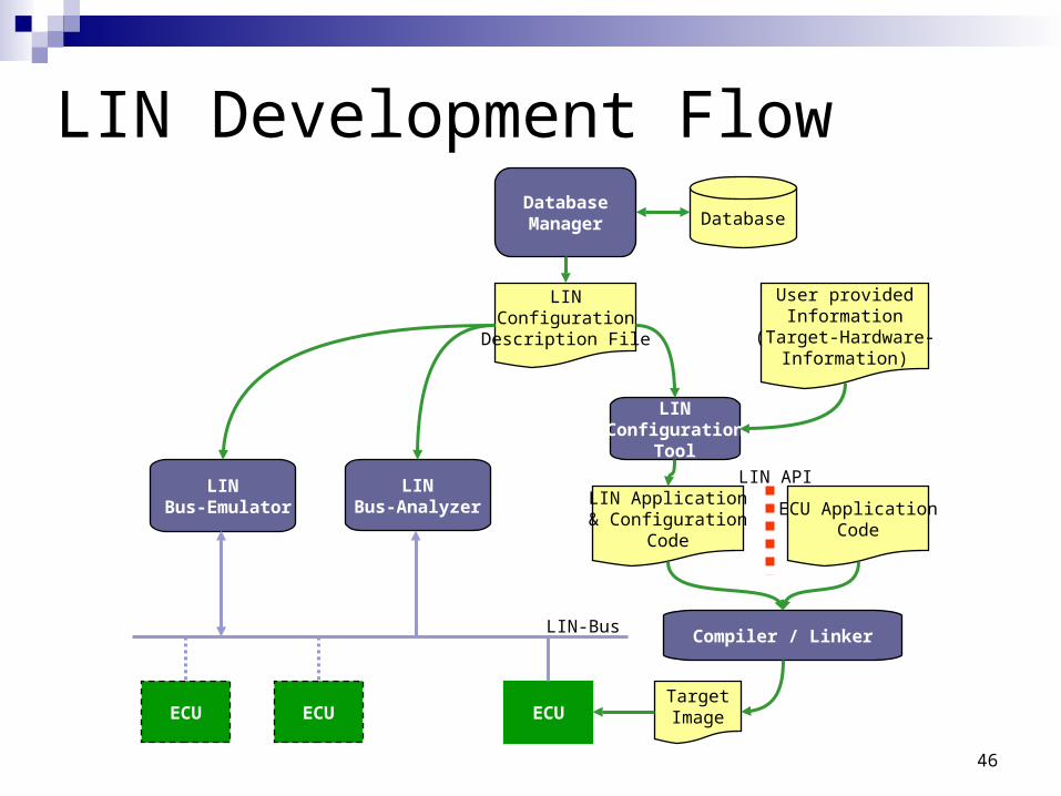
LIN Development FlowDatabaseManager Database
LINConfiguration
Description File
LINConfiguration
Tool
User providedInformation
(Target-Hardware-Information)
LIN Application& Configuration
Code
ECU ApplicationCode
LINBus-Analyzer
TargetImage
Compiler / Linker
LIN API
LIN-Bus
ECU
LIN Bus-Emulator
ECUECU