Embed Size (px)
Citation preview

The 14th
World Conference on Earthquake Engineering October 12-17, 2008, Beijing, China
(5) Unique Architectural Forms Enabled by Base-Isolation
Masayoshi Nakai1
1 General Manager, Advanced Structural Engineering Dept., Takenaka Corporation, Tokyo, Japan
Email: [email protected]
ABSTRACT :
Being freed from rationalism, recent architecture has a trend towards the integration of architecture and structure in the “façade” through collaboration between architect and structural engineer, and the trend has resulted in a number of buildings with free and novel appearances. However, in earthquake-prone countries such as Japan, where earthquake loads dominate significant part of structural design, it is often difficult and calls for hard decisions by the structural engineer to meet design requirements of the building owner and the architect. In this article are introduced projects in which the concept of “integration of façade and structure” has been achieved in earthquake-prone Japan by effectively utilizing base-isolation system, with particular focus on PRADA Boutique Aoyama building.
KEYWORDS: Base-isolation, Unique architectural form, Diagonal latticework frame, Cast steel
1. INTRODUCTION PRADA Boutique Aoyama, the brand's flagship retail store in Japan, was originally planned in Switzerland by Herzog & de Meuron (H&deM) with WGG Schnetzer Puskas as structural consultant, and then refined, detailed, finalized and realized in Japan through a collaboration of H&deM and Takenaka Corporation. 2. OUTLINE OF THE BUILDING PLAN For the outer lattice, the aim was to create a design that was both symbolic and revolutionary, befitting the building's role as a flagship PRADA Boutique. As shown in the photograph below, the building comprises a diagonal latticework frame with a façade consisting of rhombus-shaped units measuring approximately 3.2 m in width and 2.0 m in height, covered by a sash of flat and curved glass surfaces. The basic shape of the aboveground floors in plan view is a pentagon, with each side measuring approximately 10-22 meters (Fig.1). Each of the five vertical sides is set back at the top, so the plan view shape is gradually reduced at the 6th and 7th floors. Floors 1 through 4 are retail, floors 5 and 6 are offices, and the 7th floor houses the machine room. The B1F, measuring approximately 33 m x 23 m, is almost perfectly rectangular in plan view, in accordance with the shape of the site. It is used both as a storeroom and as a continuation of retail from the aboveground floors. The interior of the building has four vertical shafts for elevator and equipment duct/piping use. These are connected to the diagonal grid of the outer lattice by beams, with a floor slab matching the function of each story. The 1F, 2F, 4F and 5F stories are provided with an atrium along the outer wall,
Photo 1 Outside view of PRADA Boutique Aoyama

The 14th
World Conference on Earthquake Engineering October 12-17, 2008, Beijing, China
expressed as a continuous vertical space; moreover, the atriums on 2F, 4F and 5F are provided with horizontal tubes forming a space with a rhombus-shaped cross-section that connects the opposite sides of the pentagon in plan view; these areas are used for fitting rooms and the corridor (Fig.2). The façade of aboveground floors is of double glass mounted on each rhombus-shaped unit of the diagonal grid. A total of 840 panes of glass were used: in addition to flat glass, 205 panes of convex curved glass were used on the outside and 16 panes of concave curved glass were used on the inside.
3. STRUCTURAL CONCEPT The overall design concept for the building and the structural requirements as laid down by the owner and architects were as follows: (1) The diagonal lattice forming the outer lattice should form the structural framework while being an integral part of the glass facade (avoiding the need for vertical or horizontal members in the vertical planes). (2) The diagonal lattice members should be 250 mm in width and 300 mm in depth, including the dimensions of the finish materials. (3) The interior vertical shaft should be made as small as possible (without large horizontal rigidity), and atriums should be provided by floor openings on the 1st, 2nd, 4th and 5th floors. These requirements were fulfilled as outlined below while maintaining consistency between the architectural and mechanical designs. The lattice members are of steel construction, so all modules of the building use the same material, and each story is exactly the height of two rhomboid panels (4 m). The lattice meets each floor at intersection points on the lattice. Girders around the periphery of each floor are connected to these lattice intersections to form joints that transmit the vertical load. The peripheral girders also function as tension members (restraints on the vertical deformation of the lattice), thereby setting up a balance of horizontal forces between girders and lattice members. The floor load is supported by the lattice as well as by the interior vertical shaft through beams
Figure 1 3rd Floor Plan Figure 2 Section
Shop
Stairs
Overhead : void
Overhead : corridor tube
Overhead : floor
Stairs
Stairs
Storage
Av. G.L.
Shop
Office
Shop
Shop
Office
Office
Office
Shop
Shop Shop
Site
bou
ndar
y
Site
bou
ndar
y
Setback regulation
Setback regulations
Machine room
Eaves height
Pit for base isolation
Miyuki St.
Maximum height
Machine room
Corridor
Corridor
Backup water tank
Generator
Refresh corner
▽Design G.L.
X
Y

The 14th
World Conference on Earthquake Engineering October 12-17, 2008, Beijing, China
Outer lattice frame
Inner shaft frame
Cast-in-place pile
Horizontal tube
Seismic isolator
Floor frame
Figure 3 Overall framework
linking the peripheral girders and the shaft frames. As a result, the dead and live loads are borne almost equally by the lattice and the vertical shaft. On the other hand, most of the horizontal loading, such as the earthquake and wind loading, is carried by the lattice, since the vertical shaft has little horizontal rigidity. The lattice contains no vertical members, so it experiences greater deformation than typical column members under both long-term and short-term vertical loading, such as earthquake loading. (The vertical displacement at the uppermost floor under long-term loading is about 3 cm (Fig.4); the dimensions of the steel structural members are adjusted to accommodate this displacement.) Further, only those lattice members with upper or lower ends attached to the peripheral girders at each floor directly carry the vertical load. The other lattice members, whose ends do not attach to a floor girder (that is, the lattice members connected at corners between floors) function as anti-buckling stiffening members for the members directly carrying the load, but do not efficiently transmit the vertical load. The effects of the 2nd, 4th and 5th floor openings compound the problem of the small proportion of direct load-carrying lattice members. Further, the outer lattice framework that bears most of any earthquake loading demonstrates a lack of ductility because of its so-called brace construction. With these weaknesses, it was important to the overall structural design of the building as well as to the design of the facade itself to minimize earthquake loading on the outer lattice framework and thereby reduce deformation of the lattice. Given the restraints described and the consequent requirement to reduce earthquake loading, we proposed base-isolating the building by installing 14 laminated rubber bearings and 25 slide bearings below the basement floor. This made it possible to meet the requirements of the design concept by using fabricated H-section steel measuring 250 mm in depth and 150 mm in width for the lattice members. The lattice members were enclosed in a fire-resistant material that also serves as the finishing material (molded calcium silicate board with a minimum thickness of 20 mm). Moreover, for esthetic reasons, sash frames for the glass panels are made as compact as possible by limiting the vertical and horizontal deformation of each rhombus unit in an earthquake (to an inter-story drift of 1/300 or less). 4. OVERVIEW OF OVERALL STRUCTURE The aboveground floors of this building comprise (1) an outer lattice frame made up of a diagonal grid using built-up H-steel, (2) a floor configuration of reinforced concrete made up of steel frame beams and deck plates with built-in form, and (3) a frame (inner vertical shaft) made up primarily of vertical members (steel tubes) passing through each floor (Fig.3). The frame (horizontal tubes) of the rhombus-shaped cross-section of the atrium on the 2nd, 4th and 5th floors is a monocoque construction formed by steel with rib reinforcements. The B1F is made up of columns of steel frame construction, beams and braces. The horizontal force from the aboveground outer lattice frame is transmitted through the first floor slab of reinforced concrete to the braces provided on the periphery, etc. of the B1F. The floor of the B1F is of reinforced concrete, beneath which is a base-isolation system. However, directly beneath the high-rise portion is the B2F (approximately 40% of the B1F is taken up by equipment functions), and a clearance is provided on B1F for the elevator shaft on the main stairway side, with four base-isolation systems for the four columns provided on the B2 level. In addition, between the B1F and the base-isolation story floor is a space of approximately 1.6 m in height for use as the inspection pit for the base-isolation system. Also, between the B1F outer wall and the base slab and retaining wall is a clearance of 45 cm, out of consideration for the horizontal deformation of the base-isolation story.

The 14th
World Conference on Earthquake Engineering October 12-17, 2008, Beijing, China
5. OVERVIEW OF STRUCTURAL DESIGN 5.1. Design Load As constant vertical loads, the design takes into account the weight of the skeleton, the finished load and the equipment load, as well as the load from retail and offices (2,400 N/m2 and 1,800 N/m2, respectively, for analysis under dead and live loads and 1,300 N/m2 and 800 N/m2, respectively for analysis under seismic load). Seismic load was determined by establishing a story shear force coefficient in accordance with primary response analysis assuming a base-isolated structure, with the base shear as 0.165 (B1F) and with the distribution as a triangular distribution with 0.528 as the story shear force coefficient on the top floor (Fig.9). 5.2. Stress Deformation Stress deformation analysis for the superstructure (the portion above the base-isolation story) was performed using a three-dimensional frame model with the floor system on each story, the outer lattice frame, the inner shafts, the horizontal tubes and the lower floor portion including B1F all integrated with one another. As noted earlier, the floor weight of each story is supported by the inner shafts and the outer lattice frame, with each handling approximately 50% of the load. The vertical rigidity of the outer lattice frame was lower than that of the inner shafts, so at the floor of the top story the outer lattice frame was displaced approximately 3 cm vertically, and the maximum axial compressive force of the outer lattice grid members was 1,080 kN (Fig.4). For wind force, seismic force and other horizontal force, the outer lattice frame provided approximately 100% resistance, and horizontal displacement of the superstructure due to design seismic load when the base shear was set to 0.165 was approximately 6.5 cm at the floor of the top story, while the maximum story deformation angle was approximately 1/290 (on 6F). The structure exhibited a box-like resistance system with respect to horizontal force, and the maximum fluctuation in axial force on the tension and compression side was 1,300 kN and 1,100 kN, respectively (Fig.5).
5.3. Cross-sectional Design of Superstructure With respect to constant vertical load and horizontal load in the event of wind and seismic force, the outer lattice grid members serve primarily as members to transmit axial force. However, as bending moment will be produced along with in-plane and out-of-plane deformation of the outer lattice frame, the grid members are
29.7mm 65.6mm
Figure 4 Deformation of superstructure
(a) Dead and live loads (b) Seismic load
400.
0.
-400.
-800.
-1200.
-1600.
-2000.
400.
0.
-400.
-800.
-1200.
-1600.
-2000.
-1,030 kN
-1,078 kN
1,314 kN
-1,118 kN
(kN) (kN)
Figure 5 Axial force of superstructure
(a) Dead and live loads (b) Seismic load

The 14th
World Conference on Earthquake Engineering October 12-17, 2008, Beijing, China
designed for combined axial force and bending moment stress. The distance between supports in the grid member out-of-plane direction is approximately 7.5 m per story, and approximately 15 m for two stories in the atrium portion. However, the members that were not effective in transmitting axial force (placed at approximately 1.8 m intervals) could be evaluated as stiffening members. Therefore, the buckling length of the main axial force transmission members were accounted for 1/2 of the aforementioned distance between supports, based on buckling analysis results. Built-up H-steel was used for the grid members, with the basic size being BH-250 x 1150 x 9 x 19, and depending on the stress the flange thickness and web thickness were made 19-60 mm and 9-25 mm, respectively. At the base of the corner angles that would be subjected to the most severe stress, assembly box members (BX-250 x 150 x 25 x 40) were used. As tension members for reducing the deformation of the outer lattice frame and balancing the horizontal component of the grid member axial force (compressive force), H-steel beam members (600 mm beam depth and 400, 250 mm width) are placed around the floor slab on each story. Ideally these tension members should be placed in-plane on the outer lattice frame, but eccentricity with the core of the grid members unavoidably results in bending moment being produced in these floor peripheral members, so the H-steel is used laterally to resist combined tension and bending stress (Figs.6&7).
The joints between the grid members and the floor peripheral members (general portions and corner angles) needed to have a compact fit, so in places where the assembly materials could not be welded to one another, cast steel for welded structures (SCW 480) was used (Fig.7). For ease of construction and design considerations, cast steel was used for grid member joints in wall and roof portions not attached to floor peripheral members as well. A total of 219 cast steel members were used, including grid member joints interfacing with the floor peripheral members (a total of 99 members for (1) general portions (2) corner angle portions and (3) 1F column bases) and corner angle joints not attached to the floor (a total of 112 members (4) between walls and (5) between walls and roof). For these joints, models were fabricated for approximately 60% of the total number of members at the design stage, based on 3-dimensional CAD data, in order to confirm compliance with design requirements, and in this manner the member shape and minimum size were finalized. 5.4. Design of Base-Isolation Structure The base-isolation system was provided directly beneath the columns on B1F including the low-rise portion, and beneath the floor slab in the center where the distance between supports on the B1F slab was comparatively great. In placing the base-isolation system, as a rule, the plan called for small diameter elastic sliding bearings to be placed directly beneath the central columns where axial force fluctuations in the event of an earthquake would be low, and for lead rubber bearings (LRB) and rubber bearings (RB) to be provided at the corner angles of high-rise portions and directly beneath the corner columns in low-rise portions. At the same time, a comprehensive judgment was made regarding such matters as minimization of eccentricity in the base-isolation
Figure 6 3rd floor framing plan
Outer grid member Vertical shaft
Floor sub-beam
Floor peripheral beam
Figure 7 Detail of lattice and floor joint
Outer Diagonal Lattice
Joint of Outer Diagonal LatticeCast Steel (SCW480)
Tension Tie-Girder
Outer grid member
Cast steel joint (SCW480)
Floor peripheral beam
160
150
30
150
150
250 110 600 200 500
Glass Facade
Outer Diagonal Lattice
Joint of Outer Diagonal LatticeCast Steel (SCW480)
RC Slab
Tension Tie-Girder Sub-Beam
Glass facade Outer grid member
Cast steel joint
RC slab
Floor periphery beam Floor sub-beam

The 14th
World Conference on Earthquake Engineering October 12-17, 2008, Beijing, China
story (finding a balance between the rigidity of base-isolation systems in high-rise and low-rise portions), the target period resulting from base-isolation, control of displacement of the base-isolation story, reduction of superstructure response and so on, and a base-isolation system with six sizes of equipment outer diameters and rubber layer thicknesses was adopted. The base-isolation system that was adopted consisted of five LRB, with a diameter of 650 mm and a total rubber thickness of 160 mm, and nine RB, with a diameter of 650 mm and 600 mm and a total rubber thickness of 160 mm, and 25 elastic sliding bearings (SSR) measuring 450-300 mm in diameter, for a total of 39 bearings (Fig.8). The long-term surface pressure averaged 6.4 N/mm2 and was within the range of 0.8-17.6 N/mm2, and the surface pressure in the event of a Level 2 earthquake ground motion (to be discussed later) was 26.7 N/mm2 maximum and 0.4 N/mm2 minimum (tension), lower than the allowable tensile stress of the rubber bearing. With regard to torsion of the base-isolation story, within the range in which the shear deformation of the rubber bearing was small, the eccentricity ratio of the base-isolation story was somewhat high, but in the event of deformation whose shear strain exceeded 50%, the eccentricity ratio in the Y direction was approximately 2.5%. 6. OVERVIEW OF SEISMIC RESPONSE ANALYSIS 6.1. Base-Isolation Design Policy The following three levels were established for the earthquake ground motion input level: (1)"Earthquake ground motions that occur rarely" in Building Standard Law = Level 1 (2)"Earthquake ground motions that occur extremely rarely" in Building Standard Law = Level 2 (3)"Latitude Study Level" used to confirm the latitude for this building with respect to an earthquake greater than Level 2 The objective for earthquake-resistant safety of the building with respect to these input levels was that the isolators should be within stable deformation, performance assurance deformation and limit deformation for "Level 1" "Level 2" and "Latitude Study Level," respectively, and that the superstructure and base structure/foundation structure should be within the allowable (elastic) stress for all levels. 6.2. Input Earthquake Ground Motion Used for Design Purposes Three input earthquake ground motions for design were adopted, considering the seismicity of the region in which the building would be constructed, the characteristics of the ground at the site and conformity with the previous external force level for aseismic design. (1)Using the spectrum specified in the Japanese building regulations as the target spectrum, a simulated earthquake ground motion was created in the engineering model bedrock, and this was input to the ground model at the site to derive the input earthquake ground motion at the surface. (Abbr. ’Kokuji-1’ and ’Kokuji-2’) (2)With the aim of considering the site ground conditions that reflected the seismicity and long-term micro-motion at the construction site, a simulated earthquake ground motion that assumed an earthquake epicenter thought to affect the site was created. The fault model was the Great Kanto Earthquake (M =7.9) in 1923. (Abbr. ‘Kanto-SH’ and ‘Kanto-SV’) (3)El Centro 1940 NS, Taft 1952 EW and Hachinohe 1968 NS (three waves that were used in aseismic design even prior to the revision of the Building Standard Law, as reference waves and earthquake ground motions that
× + On the B2F
×:Center of rigidity
+:Center of gravity
X
Y
Figure 8 Layout of seismic isolators
Symbol Type Diameter Quantity
LRB 650 5
650 4
600 5
450 5
350 7
300 13
39
RB
SSR
Total
Diameter
SSR
Quantity Type Symbol
Total
The 14th
World Conference on Earthquake Engineering October 12-17, 2008, Beijing, China
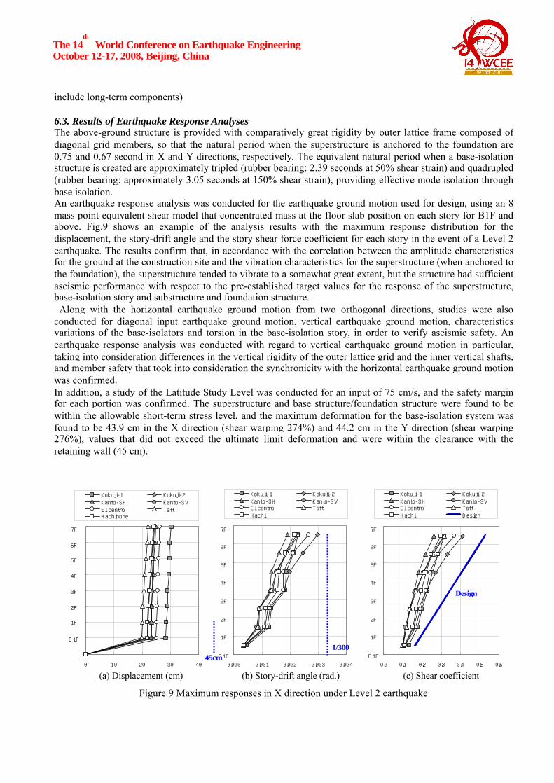
include long-term components) 6.3. Results of Earthquake Response Analyses The above-ground structure is provided with comparatively great rigidity by outer lattice frame composed of diagonal grid members, so that the natural period when the superstructure is anchored to the foundation are 0.75 and 0.67 second in X and Y directions, respectively. The equivalent natural period when a base-isolation structure is created are approximately tripled (rubber bearing: 2.39 seconds at 50% shear strain) and quadrupled (rubber bearing: approximately 3.05 seconds at 150% shear strain), providing effective mode isolation through base isolation. An earthquake response analysis was conducted for the earthquake ground motion used for design, using an 8 mass point equivalent shear model that concentrated mass at the floor slab position on each story for B1F and above. Fig.9 shows an example of the analysis results with the maximum response distribution for the displacement, the story-drift angle and the story shear force coefficient for each story in the event of a Level 2 earthquake. The results confirm that, in accordance with the correlation between the amplitude characteristics for the ground at the construction site and the vibration characteristics for the superstructure (when anchored to the foundation), the superstructure tended to vibrate to a somewhat great extent, but the structure had sufficient aseismic performance with respect to the pre-established target values for the response of the superstructure, base-isolation story and substructure and foundation structure. Along with the horizontal earthquake ground motion from two orthogonal directions, studies were also conducted for diagonal input earthquake ground motion, vertical earthquake ground motion, characteristics variations of the base-isolators and torsion in the base-isolation story, in order to verify aseismic safety. An earthquake response analysis was conducted with regard to vertical earthquake ground motion in particular, taking into consideration differences in the vertical rigidity of the outer lattice grid and the inner vertical shafts, and member safety that took into consideration the synchronicity with the horizontal earthquake ground motion was confirmed. In addition, a study of the Latitude Study Level was conducted for an input of 75 cm/s, and the safety margin for each portion was confirmed. The superstructure and base structure/foundation structure were found to be within the allowable short-term stress level, and the maximum deformation for the base-isolation system was found to be 43.9 cm in the X direction (shear warping 274%) and 44.2 cm in the Y direction (shear warping 276%), values that did not exceed the ultimate limit deformation and were within the clearance with the retaining wall (45 cm).
1
2
3
4
5
6
7
8
0.0 0.1 0.2 0.3 0.4 0.5 0.6
Kokuji-1 Kokuji-2Kanto-SH Kanto-SVEl centro TaftHachi no h e Design
7F
6F
5F
4F
3F
2F
1F
B1F
Design
1
2
3
4
5
6
7
8
0.000 0.001 0.002 0.003 0.004
Kokuji-1 Kokuji-2Kanto-SH Kanto-SVEl centro TaftHachi no h e
7F
6F
5F
4F
3F
2F
1F
B1F1/300
0
1
2
3
4
5
6
7
8
0 10 20 30 40
Kokuji-1 Kokuji-2Kanto-SH Kanto-SVEl centro TaftHachinohe
7F
6F
5F
4F
3F
2F
1F
B1F
45cm
Figure 9 Maximum responses in X direction under Level 2 earthquake
(a) Displacement (cm) (b) Story-drift angle (rad.) (c) Shear coefficient
The 14th
World Conference on Earthquake Engineering October 12-17, 2008, Beijing, China
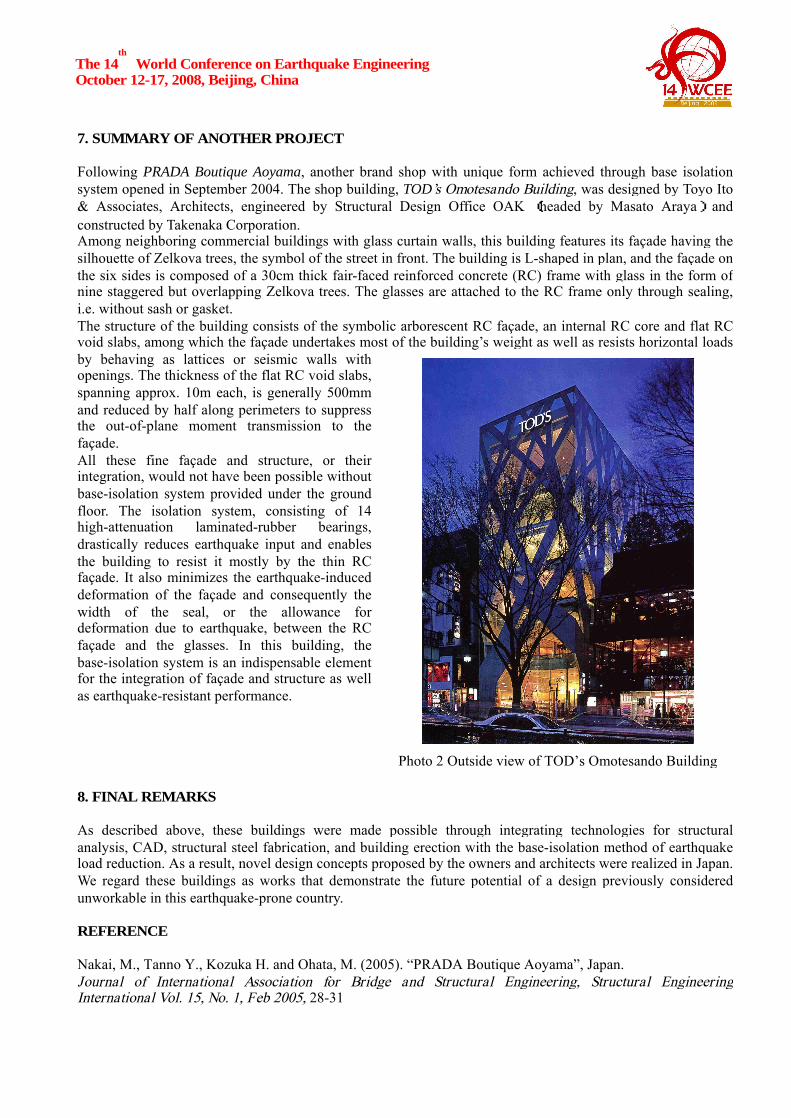
7. SUMMARY OF ANOTHER PROJECT Following PRADA Boutique Aoyama, another brand shop with unique form achieved through base isolation system opened in September 2004. The shop building, TOD’s Omotesando Building, was designed by Toyo Ito & Associates, Architects, engineered by Structural Design Office OAK (headed by Masato Araya) and constructed by Takenaka Corporation. Among neighboring commercial buildings with glass curtain walls, this building features its façade having the silhouette of Zelkova trees, the symbol of the street in front. The building is L-shaped in plan, and the façade on the six sides is composed of a 30cm thick fair-faced reinforced concrete (RC) frame with glass in the form of nine staggered but overlapping Zelkova trees. The glasses are attached to the RC frame only through sealing, i.e. without sash or gasket. The structure of the building consists of the symbolic arborescent RC façade, an internal RC core and flat RC void slabs, among which the façade undertakes most of the building’s weight as well as resists horizontal loads by behaving as lattices or seismic walls with openings. The thickness of the flat RC void slabs, spanning approx. 10m each, is generally 500mm and reduced by half along perimeters to suppress the out-of-plane moment transmission to the façade. All these fine façade and structure, or their integration, would not have been possible without base-isolation system provided under the ground floor. The isolation system, consisting of 14 high-attenuation laminated-rubber bearings, drastically reduces earthquake input and enables the building to resist it mostly by the thin RC façade. It also minimizes the earthquake-induced deformation of the façade and consequently the width of the seal, or the allowance for deformation due to earthquake, between the RC façade and the glasses. In this building, the base-isolation system is an indispensable element for the integration of façade and structure as well as earthquake-resistant performance. 8. FINAL REMARKS As described above, these buildings were made possible through integrating technologies for structural analysis, CAD, structural steel fabrication, and building erection with the base-isolation method of earthquake load reduction. As a result, novel design concepts proposed by the owners and architects were realized in Japan. We regard these buildings as works that demonstrate the future potential of a design previously considered unworkable in this earthquake-prone country. REFERENCE Nakai, M., Tanno Y., Kozuka H. and Ohata, M. (2005). “PRADA Boutique Aoyama”, Japan. Journal of International Association for Bridge and Structural Engineering, Structural Engineering International Vol. 15, No. 1, Feb 2005, 28-31
Photo 2 Outside view of TOD’s Omotesando Building