Embed Size (px)
Citation preview
Chapter 4 Unrestrained Beams 15/08/2007
J Y R Liew 1
Chapter 2: Member Design
Section 4: Unrestrained Beams
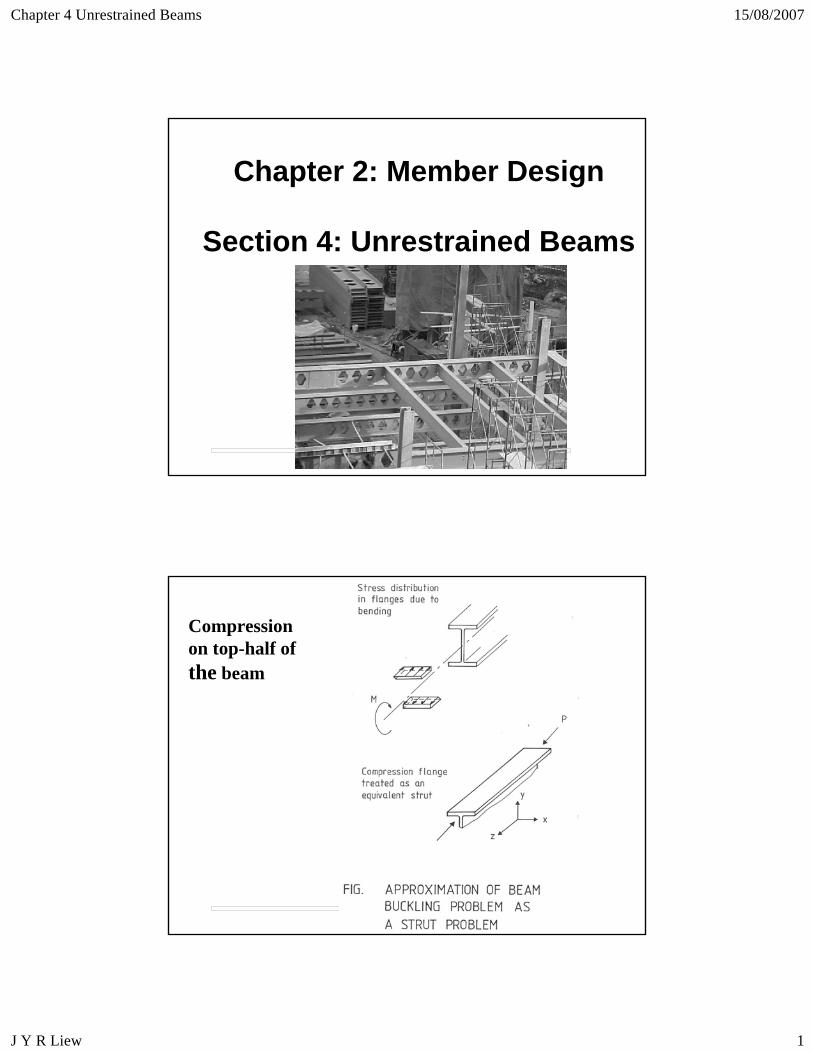
Compression on top-half of the beam
Chapter 4 Unrestrained Beams 15/08/2007
J Y R Liew 2
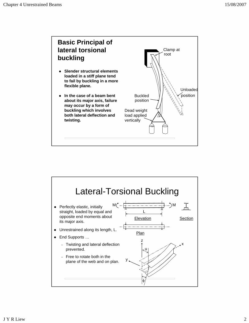
Basic Principal of lateral torsionalbuckling
Dead weightload appliedvertically
Buckledposition
Unloadedposition
Clamp atroot
In the case of a beam bent about its major axis, failure may occur by a form of buckling which involves both lateral deflection and twisting.
Slender structural elements loaded in a stiff plane tend to fail by buckling in a more flexible plane.
Lateral-Torsional BucklingM M
L
Elevation Section
Plan
y
zx
u
φ
Perfectly elastic, initially straight, loaded by equal and opposite end moments about its major axis.
Unrestrained along its length, L.
End Supports …
– Twisting and lateral deflection prevented.
– Free to rotate both in the plane of the web and on plan.
Chapter 4 Unrestrained Beams 15/08/2007
J Y R Liew 3
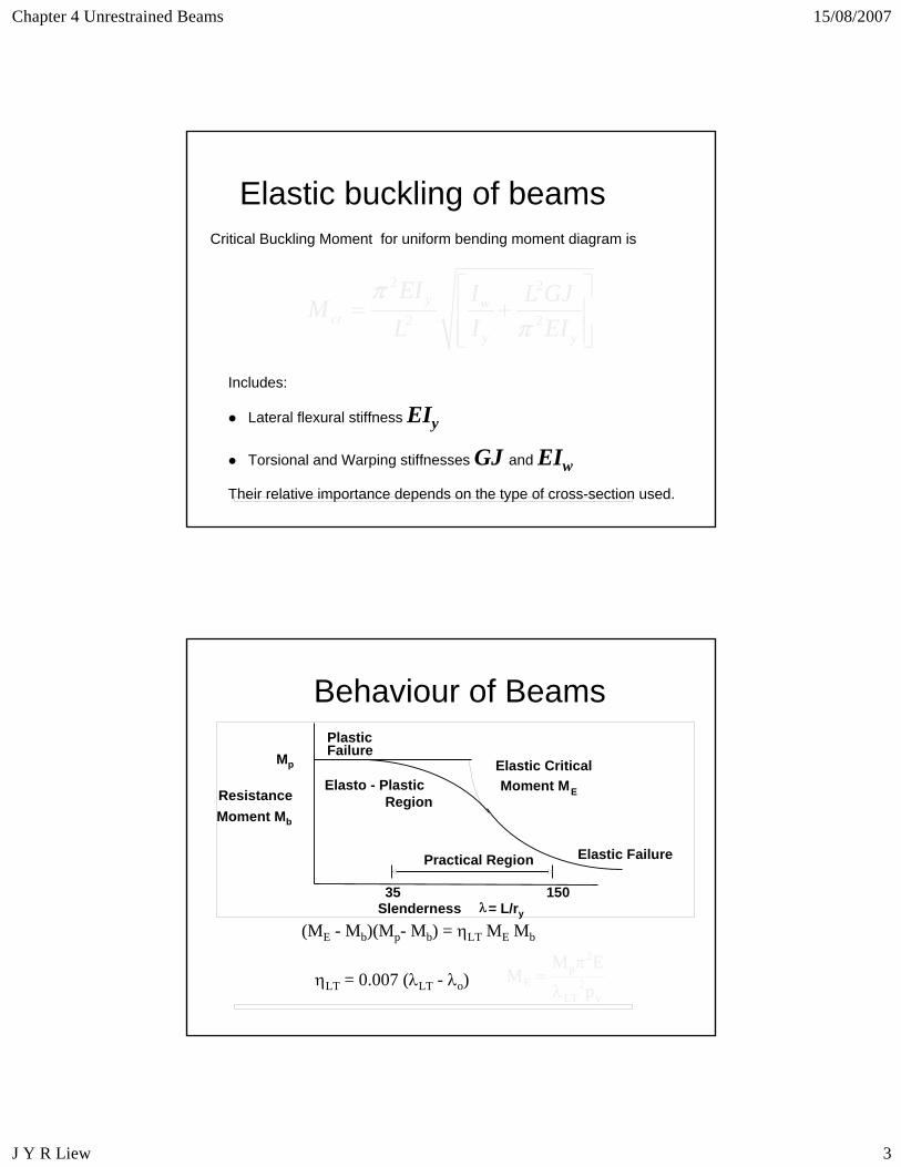
Elastic buckling of beams
Includes:
Lateral flexural stiffness EIy
Torsional and Warping stiffnesses GJ and EIw
Their relative importance depends on the type of cross-section used.
2 2
2 2y w
cry y
EI I L GJML I EI
ππ
⎡ ⎤= +⎢ ⎥
⎢ ⎥⎣ ⎦
Critical Buckling Moment for uniform bending moment diagram is
Behaviour of Beams
ηLT = 0.007 (λLT - λo)
(ME - Mb)(Mp- Mb) = ηLT ME Mb
y2
LT
2p
E pEM
Mλ
π=
35 150
Practical Region Elastic Failure
PlasticFailure
Elasto - PlasticRegion
Elastic CriticalMoment ME
Slenderness = L/ry
ResistanceMoment Mb
Mp
λ
Chapter 4 Unrestrained Beams 15/08/2007
J Y R Liew 4
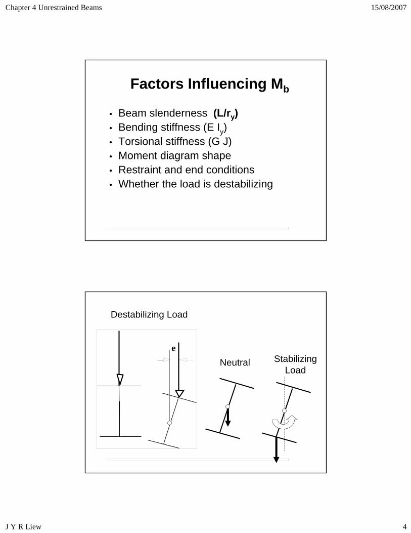
Factors Influencing Mb
• Beam slenderness (L/ry) • Bending stiffness (E Iy)• Torsional stiffness (G J)• Moment diagram shape• Restraint and end conditions• Whether the load is destabilizing
Destabilizing Load
Stabilizing Load
Neutrale
Chapter 4 Unrestrained Beams 15/08/2007
J Y R Liew 5
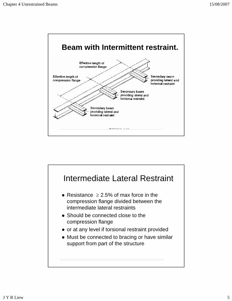
Beam with Intermittent restraint.
Intermediate Lateral Restraint
Resistance ≥ 2.5% of max force in the compression flange divided between the intermediate lateral restraintsShould be connected close to the compression flangeor at any level if torsional restraint providedMust be connected to bracing or have similar support from part of the structure
Chapter 4 Unrestrained Beams 15/08/2007
J Y R Liew 6
BAY 1Triangulated
BAY 2Tied to braced bay
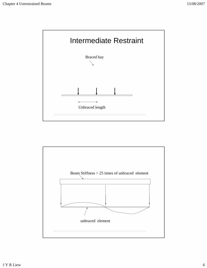
Intermediate Restraint
Unbraced length
Braced bay
Beam Stiffness > 25 times of unbraced element
unbraced element
Chapter 4 Unrestrained Beams 15/08/2007
J Y R Liew 7
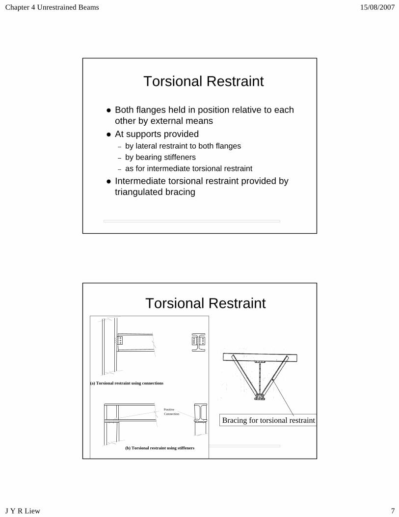
Torsional Restraint
Both flanges held in position relative to each other by external meansAt supports provided – by lateral restraint to both flanges– by bearing stiffeners– as for intermediate torsional restraint
Intermediate torsional restraint provided by triangulated bracing
Torsional Restraint
(a) Torsional restraint using connections
(b) Torsional restraint using stiffeners
Positive Connection
Bracing for torsional restraint
Chapter 4 Unrestrained Beams 15/08/2007
J Y R Liew 8
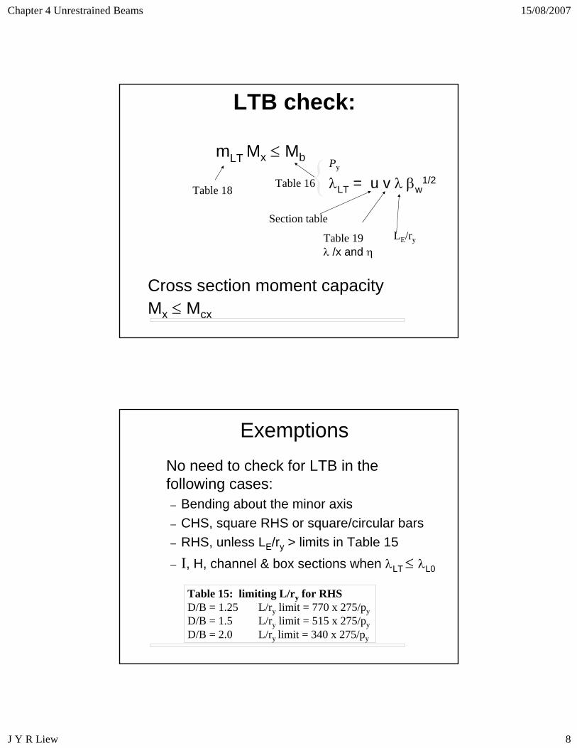
LTB check:
mLT Mx ≤ Mb
Cross section moment capacityMx ≤ Mcx
Table 18
Py
λLT = u v λ βw1/2
Table 19λ /x and η
LE/ry
Section table
{Table 16
ExemptionsNo need to check for LTB in the following cases:– Bending about the minor axis– CHS, square RHS or square/circular bars– RHS, unless LE/ry > limits in Table 15– I, H, channel & box sections when λLT ≤ λL0
Table 15: limiting L/ry for RHSD/B = 1.25 L/ry limit = 770 x 275/pyD/B = 1.5 L/ry limit = 515 x 275/pyD/B = 2.0 L/ry limit = 340 x 275/py
Chapter 4 Unrestrained Beams 15/08/2007
J Y R Liew 9
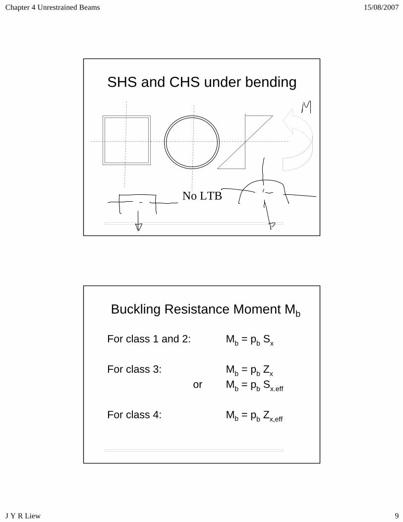
SHS and CHS under bending
No LTB
Buckling Resistance Moment Mb
For class 1 and 2: Mb = pb Sx
For class 3: Mb = pb Zx
or Mb = pb Sx.eff
For class 4: Mb = pb Zx,eff
Chapter 4 Unrestrained Beams 15/08/2007
J Y R Liew 10
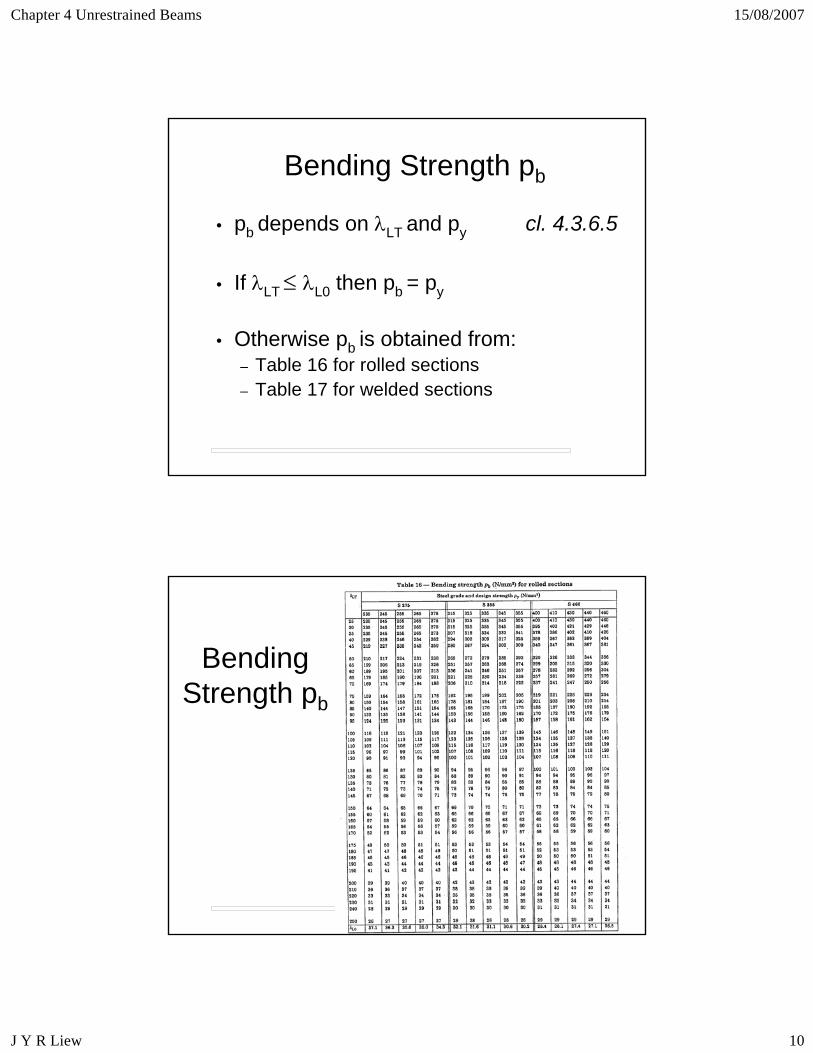
Bending Strength pb
• pb depends on λLT and py cl. 4.3.6.5
• If λLT ≤ λL0 then pb = py
• Otherwise pb is obtained from:– Table 16 for rolled sections– Table 17 for welded sections
Bending Strength pb
Chapter 4 Unrestrained Beams 15/08/2007
J Y R Liew 11
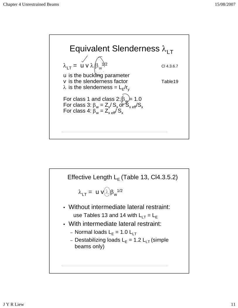
Equivalent Slenderness λLT
λLT = u v λ βw1/2 Cl 4.3.6.7
u is the buckling parameterv is the slenderness factor Table19λ is the slenderness = LE/ry
For class 1 and class 2: βw = 1.0For class 3: βw = Zx/ Sx or Sx eff/SxFor class 4: βw = Zx eff/ Sx
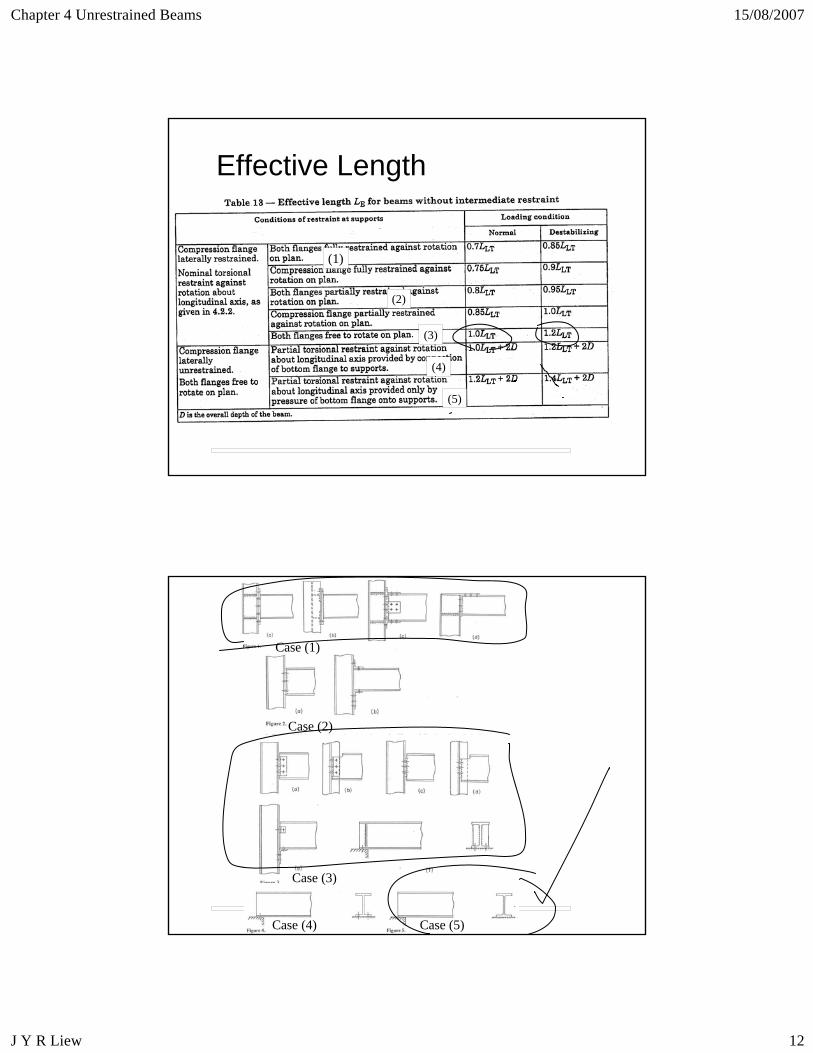
Effective Length LE (Table 13, Cl4.3.5.2)
• Without intermediate lateral restraint: use Tables 13 and 14 with LLT = LE
• With intermediate lateral restraint:– Normal loads LE = 1.0 LLT
– Destabilizing loads LE = 1.2 LLT (simple beams only)
λLT = u v λ βw1/2
Chapter 4 Unrestrained Beams 15/08/2007
J Y R Liew 12
Effective Length
(1)
(3)
(2)
(4)
(5)
Case (1)
Case (2)
Case (3)
Case (4) Case (5)
Chapter 4 Unrestrained Beams 15/08/2007
J Y R Liew 13
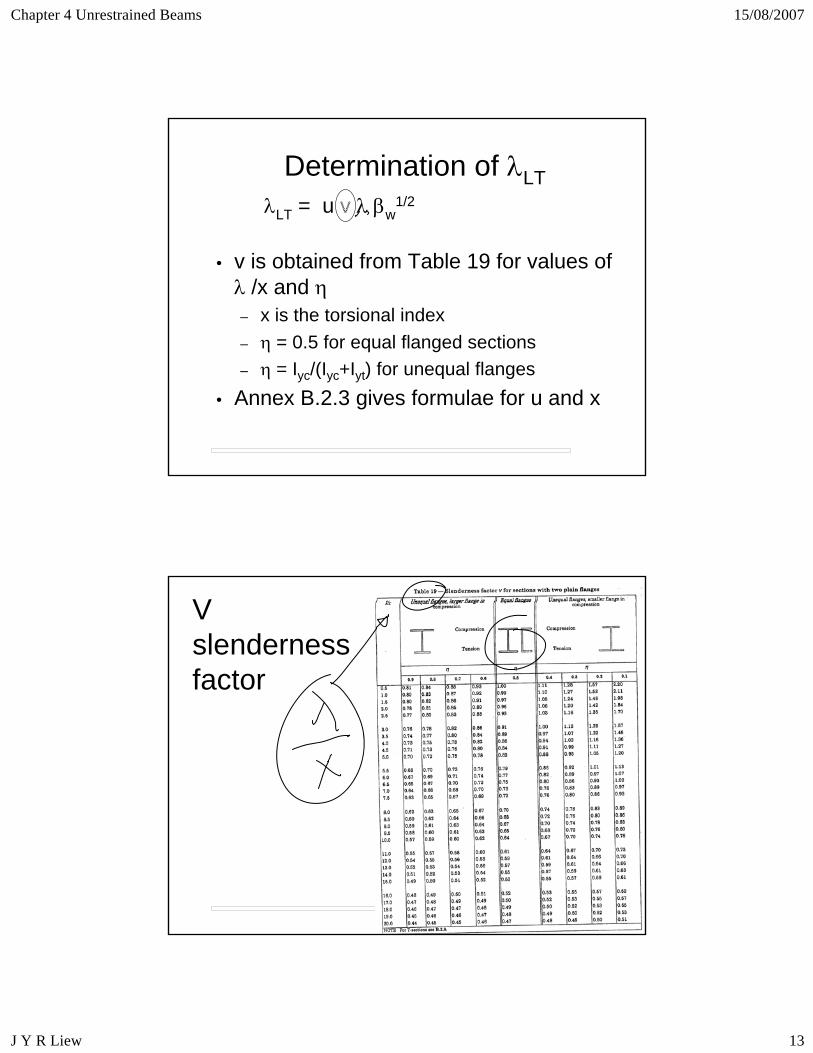
Determination of λLT
• v is obtained from Table 19 for values of λ /x and η – x is the torsional index– η = 0.5 for equal flanged sections– η = Iyc/(Iyc+Iyt) for unequal flanges
• Annex B.2.3 gives formulae for u and x
λLT = u v λ βw1/2
V slenderness factor
Chapter 4 Unrestrained Beams 15/08/2007
J Y R Liew 14
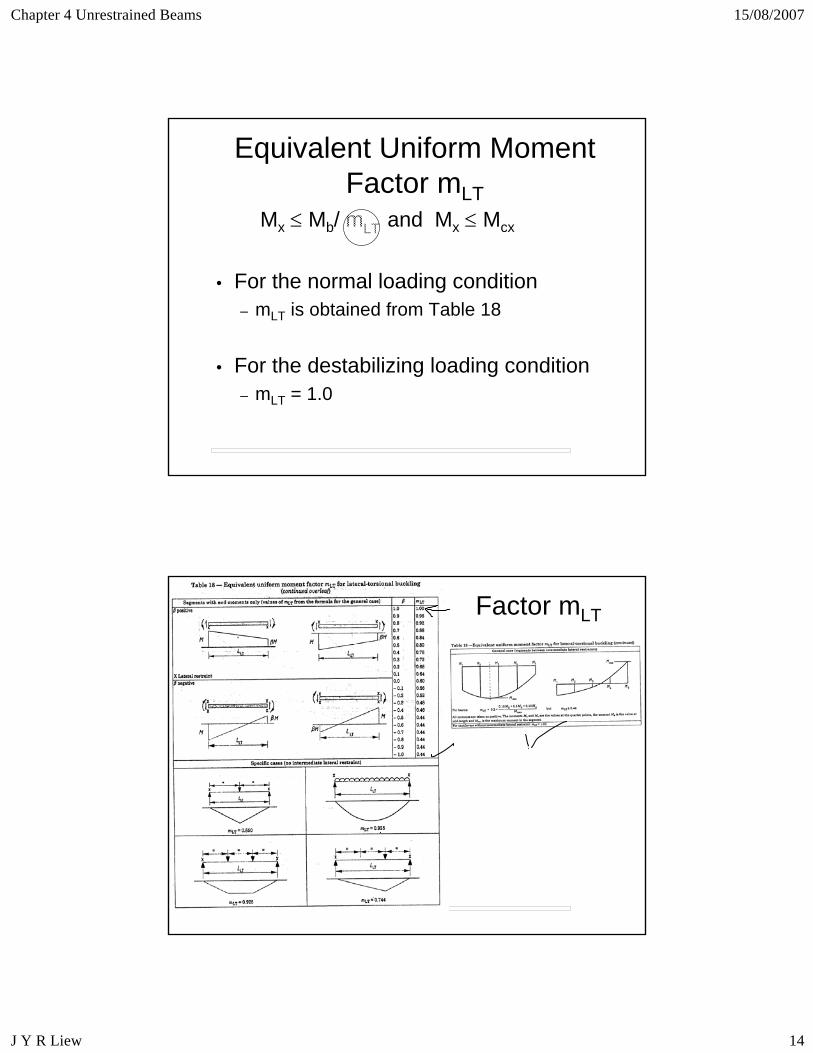
Equivalent Uniform Moment Factor mLT
• For the normal loading condition– mLT is obtained from Table 18
• For the destabilizing loading condition– mLT = 1.0
Mx ≤ Mb/ mLT and Mx ≤ Mcx
Factor mLT
Chapter 4 Unrestrained Beams 15/08/2007
J Y R Liew 15
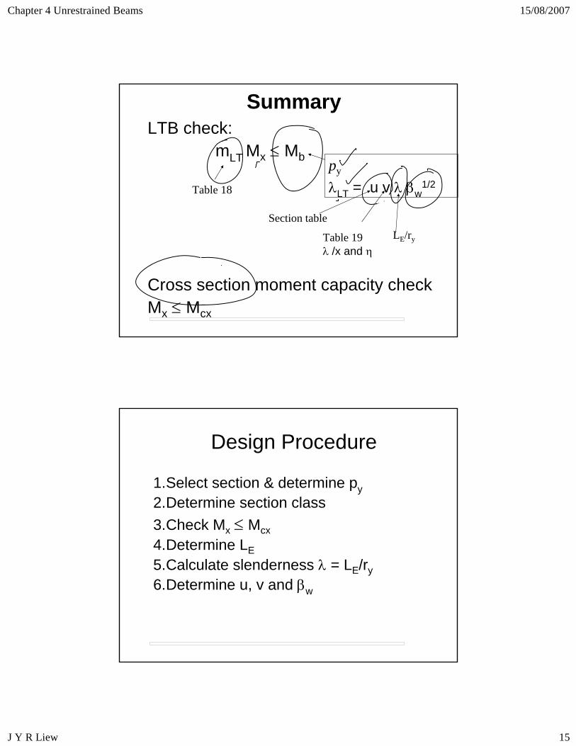
SummaryLTB check:
mLT Mx ≤ Mb
Cross section moment capacity checkMx ≤ Mcx
Table 18
py
λLT = u v λ βw1/2
Table 19λ /x and η
LE/ry
Section table
Design Procedure
1.Select section & determine py2.Determine section class3.Check Mx ≤ Mcx4.Determine LE5.Calculate slenderness λ = LE/ry6.Determine u, v and βw
Chapter 4 Unrestrained Beams 15/08/2007
J Y R Liew 16
Design Procedure continued
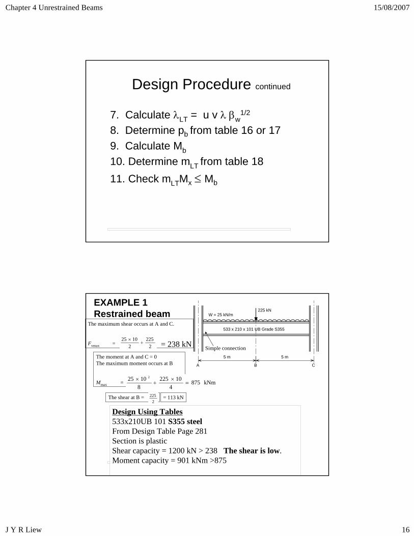
7. Calculate λLT = u v λ βw1/2
8. Determine pb from table 16 or 179. Calculate Mb
10. Determine mLT from table 1811. Check mLTMx ≤ Mb
The moment at A and C = 0The maximum moment occurs at B
Mmax =
EXAMPLE 1Restrained beam
5 m 5 m
225 kNW = 25 kN/m
A B C
533 x 210 x 101 UB Grade S355The maximum shear occurs at A and C.
Fvmax = 2225
21025
+×
kNm8754
102258
1025 2
=×
+×
The shear at B =2
225 = 113 kN
= 238 kN
Design Using Tables533x210UB 101 S355 steelFrom Design Table Page 281Section is plastic Shear capacity = 1200 kN > 238 The shear is low.Moment capacity = 901 kNm >875
Simple connection
Chapter 4 Unrestrained Beams 15/08/2007
J Y R Liew 17
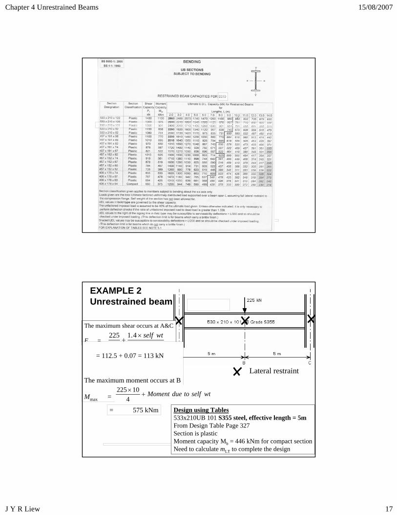
EXAMPLE 2Unrestrained beam
The maximum shear occurs at A&C
Fvmax= 24.1
2225 wtself×
+
= 112.5 + 0.07 = 113 kN
The maximum moment occurs at B
Mmax = wtselftodueMoment+×
410225
= 575 kNm Design using Tables533x210UB 101 S355 steel, effective length = 5mFrom Design Table Page 327Section is plastic Moment capacity Mb = 446 kNm for compact sectionNeed to calculate mLT to complete the design
Lateral restraint
Chapter 4 Unrestrained Beams 15/08/2007
J Y R Liew 18
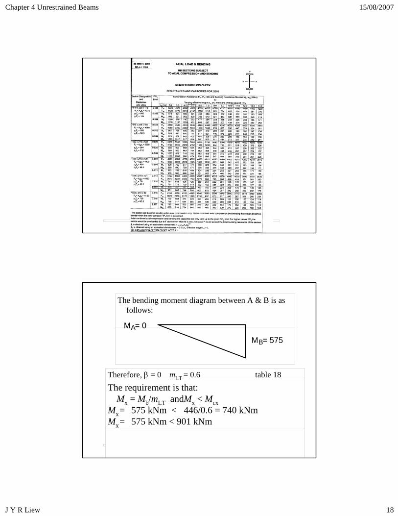
The bending moment diagram between A & B is as follows:
M = 575B
AM = 0
The requirement is that:Mx = Mb/mLT andMx < Mcx
Mx= 575 kNm < 446/0.6 = 740 kNmMx= 575 kNm < 901 kNm
Therefore, β = 0 mLT = 0.6 table 18
Chapter 4 Unrestrained Beams 15/08/2007
J Y R Liew 19
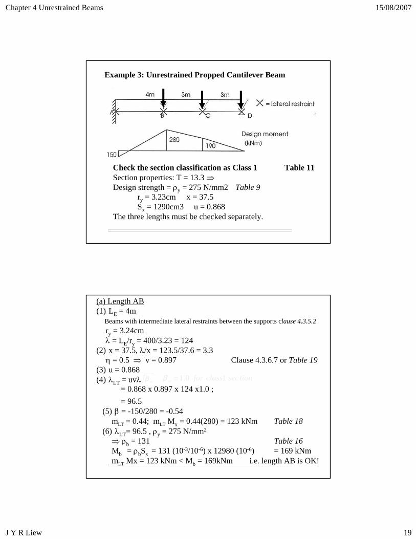
Example 3: Unrestrained Propped Cantilever Beam
Check the section classification as Class 1 Table 11Section properties: T = 13.3 ⇒Design strength = ρy = 275 N/mm2 Table 9
ry = 3.23cm x = 37.5Sx = 1290cm3 u = 0.868
The three lengths must be checked separately.
(a) Length AB(1) LE = 4m
Beams with intermediate lateral restraints between the supports clause 4.3.5.2ry = 3.24cm λ = LE/ry = 400/3.23 = 124
(2) x = 37.5, λ/x = 123.5/37.6 = 3.3 η = 0.5 ⇒ v = 0.897 Clause 4.3.6.7 or Table 19
(3) u = 0.868(4) λLT = uvλ wβ
= 0.868 x 0.897 x 124 x1.0 ; 1 0 1w . for class sec tionβ =
= 96.5 (5) β = -150/280 = -0.54
mLT = 0.44; mLT Mx = 0.44(280) = 123 kNm Table 18(6) λLT= 96.5 , ρy = 275 N/mm2
⇒ ρb = 131 Table 16Mb = ρbSx = 131 (10-3/10-6) x 12980 (10-6) = 169 kNmmLT Mx = 123 kNm < Mb = 169kNm i.e. length AB is OK!
Chapter 4 Unrestrained Beams 15/08/2007
J Y R Liew 20
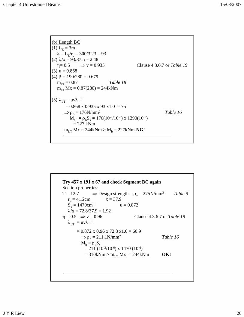
(b) Length BC (1) LE = 3m
λ = LE/ry = 300/3.23 = 93 (2) λ/x = 93/37.5 = 2.48
η= 0.5 ⇒ v = 0.935 Clause 4.3.6.7 or Table 19(3) u = 0.868 (4) β = 190/280 = 0.679
mLT = 0.87 Table 18mLT Mx = 0.87(280) = 244kNm
(5) λLT = uvλ wβ
= 0.868 x 0.935 x 93 x1.0 = 75 ⇒ ρb = 176N/mm2 Table 16
Mb = ρbSx = 176(10-3/10-6) x 1290(10-6) = 227 kNm
mLT Mx = 244kNm > Mb = 227kNm NG!
Try 457 x 191 x 67 and check Segment BC againSection properties: T = 12.7 ⇒ Design strength = ρy = 275N/mm2 Table 9
ry = 4.12cm x = 37.9 Sx = 1470cm3 u = 0.872 λ/x = 72.8/37.9 = 1.92
η = 0.5 ⇒ v = 0.96 Clause 4.3.6.7 or Table 19λLT = uvλ wβ
= 0.872 x 0.96 x 72.8 x1.0 = 60.9 ⇒ ρb = 211.1N/mm2 Table 16Mb = ρbSx
= 211 (10-3/10-6) x 1470 (10-6) = 310kNm > mLT Mx = 244kNm OK!
Chapter 4 Unrestrained Beams 15/08/2007
J Y R Liew 21
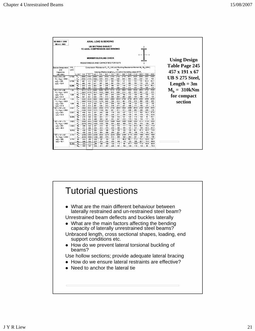
Using Design Table Page 245457 x 191 x 67 UB S 275 Steel,
Length = 3mMb = 310kNm
for compact section
Tutorial questionsWhat are the main different behaviour between laterally restrained and un-restrained steel beam?
Unrestrained beam deflects and buckles laterallyWhat are the main factors affecting the bending capacity of laterally unrestrained steel beams?
Unbraced length, cross sectional shapes, loading, end support conditions etc.How do we prevent lateral torsional buckling of beams?
Use hollow sections; provide adequate lateral bracing How do we ensure lateral restraints are effective?Need to anchor the lateral tie
Chapter 4 Unrestrained Beams 15/08/2007
J Y R Liew 22
Reading assignment:
BS5950:Part1 Cls 4.2 & 4.3Chapter 2 Sections 3 & 4Homework : Beams


![Rachmaninov 3rd Piano Concerto [First Movement] · PDF file53-g e5 = 5 !5 = 5 5 5 5 5 4 5 5 =5 5 = 5e5 5 5 5 5 5 5 5e5 5 5!55 5 5 5 5 5e5 5 5 5 5 5 5! 5 $3e55 5 5: 5 5 5 55 5e 55 5](https://img.pdfslide.net/doc/110x75/5a78944a7f8b9a1f128d15db/rachmaninov-3rd-piano-concerto-first-movement-53-g-e5-5-5-5-5-5-5-5-4-5.jpg)


![[XLS] · Web view4.95. 4.95. 5. 5. 5. 5. 5. 5. 4.95. 5. 5. 4.95. 4.95. 5. 4.95. 5. 5. 4.95. 4.95. 5. 5. 5. 5. 5. 5. 4.95. 5. 4.95. 4.95. 4.95. 4.95. 5. 5. 4.95. 4.95. 5. 5. 4.95](https://img.pdfslide.net/doc/110x75/5ba3371b09d3f2cc2e8da3f6/xls-web-view495-495-5-5-5-5-5-5-495-5-5-495-495-5-495.jpg)