Embed Size (px)
Citation preview
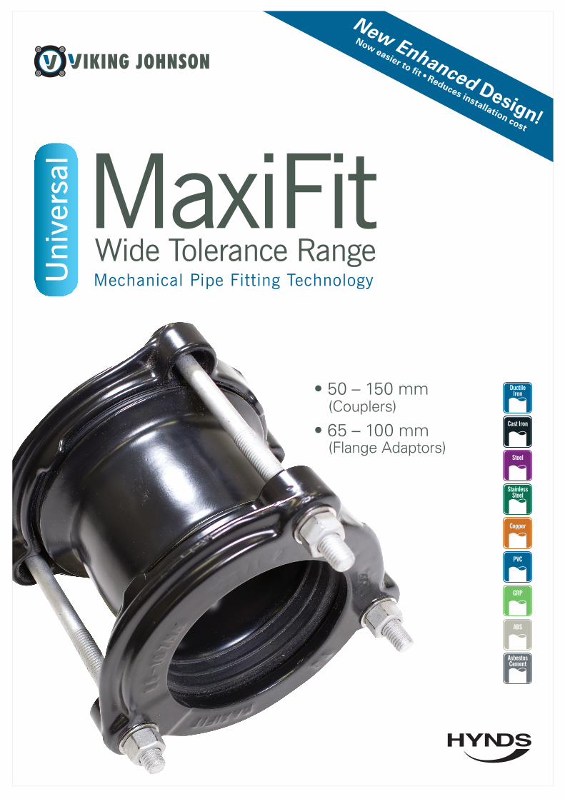
New Enhanced Design!
Now easier to fit • Reduces installation cost
• 50 – 150 mm (Couplers)
• 65 – 100 mm (Flange Adaptors)
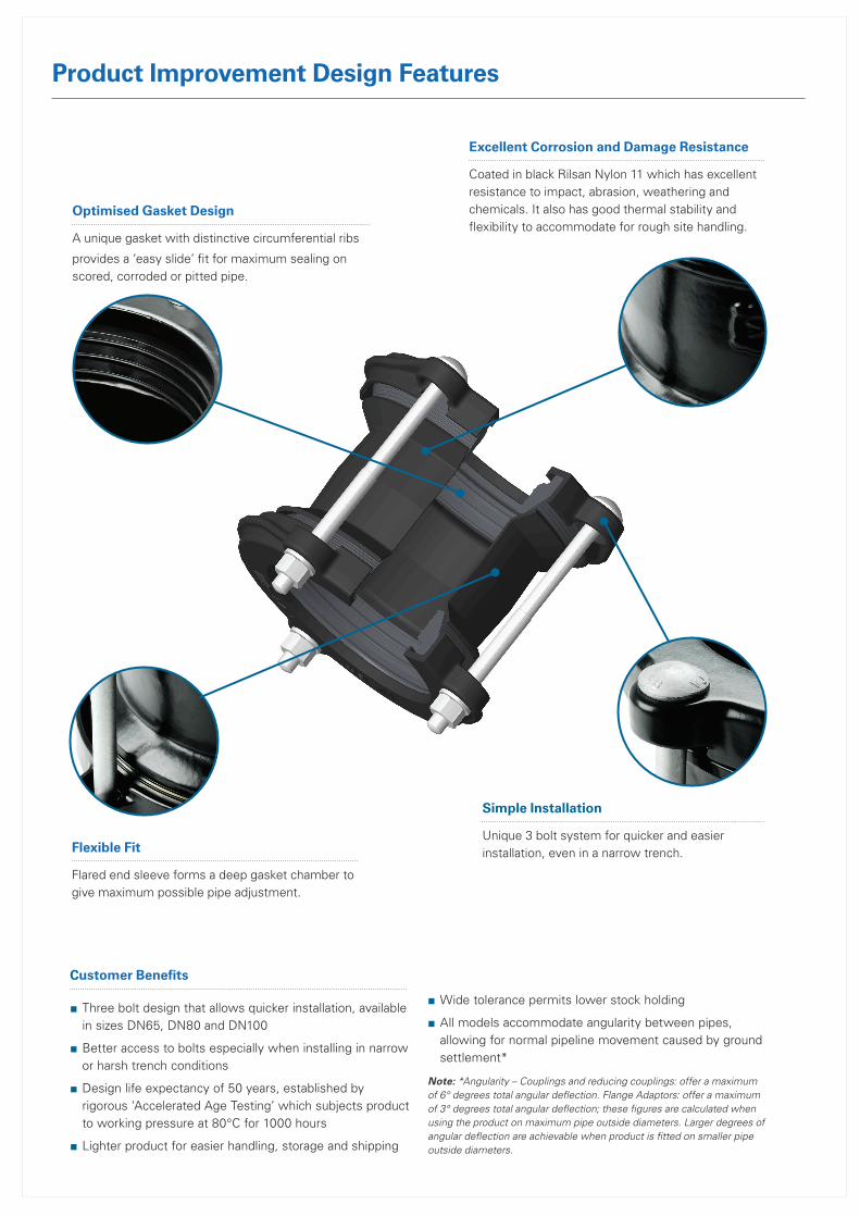
Optimised Gasket Design
A unique gasket with distinctive circumferential ribs
provides a ‘easy slide’ fit for maximum sealing on scored, corroded or pitted pipe.
Excellent Corrosion and Damage Resistance
Coated in black Rilsan Nylon 11 which has excellent resistance to impact, abrasion, weathering and chemicals. It also has good thermal stability and flexibility to accommodate for rough site handling.
Flexible Fit
Flared end sleeve forms a deep gasket chamber to give maximum possible pipe adjustment.
Simple Installation
Unique 3 bolt system for quicker and easier installation, even in a narrow trench.
Customer Benefits
■ Three bolt design that allows quicker installation, available in sizes DN65, DN80 and DN100
■ Better access to bolts especially when installing in narrow or harsh trench conditions
■ Design life expectancy of 50 years, established by rigorous ‘Accelerated Age Testing’ which subjects product to working pressure at 80°C for 1000 hours
■ Lighter product for easier handling, storage and shipping
■ Wide tolerance permits lower stock holding
■ All models accommodate angularity between pipes, allowing for normal pipeline movement caused by ground settlement*
Note: *Angularity – Couplings and reducing couplings: offer a maximum of 6° degrees total angular deflection. Flange Adaptors: offer a maximum of 3° degrees total angular deflection; these figures are calculated when using the product on maximum pipe outside diameters. Larger degrees of angular deflection are achievable when product is fitted on smaller pipe outside diameters.
Product Improvement Design Features
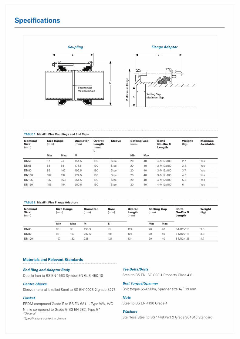
TaBlE 1 MaxiFit Plus Couplings and End Caps
NominalSize(mm)
Size Range(mm)
Diameter(mm)
OverallLength(mm)L
Sleeve Setting Gap(mm)
BoltsNo-Dia X Length
Weight(Kg)
MaxiCap Available
Min Max M Min Max
DN50 57 74 154.5 190 Steel 20 40 4-M12x180 2.7 Yes
DN65 63 85 173.5 190 Steel 20 40 3-M12x180 3.2 Yes
DN80 85 107 195.5 190 Steel 20 40 3-M12x180 3.7 Yes
DN100 107 132 224.5 190 Steel 20 40 3-M12x180 4.5 Yes
DN125 132 158 254.5 190 Steel 20 40 4-M12x180 5.2 Yes
DN150 158 184 280.5 190 Steel 20 40 4-M12x180 6 Yes
TaBlE 2 MaxiFit Plus Flange adaptors
NominalSize(mm)
Size Range(mm)
Diameter(mm)
Bore(mm)
OverallLength(mm)
Setting Gap(mm)
BoltsNo-Dia X Length
Weight(Kg)
Min Max M S Min Max
DN65 63 85 196.9 75 124 20 40 3-M12x115 3.6
DN80 85 107 202.5 101 124 20 40 3-M12x115 3.8
DN100 107 132 228 121 134 20 40 3-M12x125 4.7
Materials and Relevant Standards
End Ring and Adaptor Body
Ductile Iron to BS EN 1563 Symbol EN GJS-450-10
Centre Sleeve
Sleeve material is rolled Steel to BS EN10025-2 grade S275
Gasket
EPDM compound Grade E to BS EN 681-1, Type WA, WC
Nitrile compound to Grade G BS EN 682, Type G* *Optional
*Specifications subject to change
Tee Bolts/Bolts
Steel to BS EN ISO 898-1 Property Class 4.8
Bolt Torque/Spanner
Bolt torque 55-65Nm, Spanner size A/F 19 mm
Nuts
Steel to BS EN 4190 Grade 4
Washers
Stainless Steel to BS 1449:Part 2 Grade 304S15 Standard
Speci�cations
MaxiFit Plus Couplings & Flange Adaptors
End Ring and Adaptor BodyDuctile Iron to B S EN 1563 Symbol EN GJ S-450-10
Centre SleeveSleeve material is rolled Steel to BS EN 10025-2 grade S275 or Ductile Iron to BS EN1563 symbol EN GJS-450-10
GasketEPDM compound Grade E to B S EN 681-1, Type WA, WC
Nitrile compound to Grade G B S EN 682, Type G
Tee Bolts/BoltsSteel to B S EN ISO 898-1 Property Class 4.8
Bolt Torque/SpannerBolt torque 55-65Nm, Spanner size A/F 19mm
NutsSteel to B S EN 4190 Grade 4
WashersStainless Steel to B S 1449:Part 2 Grade 304 S15 Standard
Materials & Relevant Standards
MaxiFit Plus Couplings
MaxiFit Plus Flange Adaptors
Every e�ort has been made to ensure that the information contained in this publication is accurate at the time of publishing. Crane Ltd assumes no responsibility or liability for typographical errors or omissions or for any misinterpretation of the information within the publication and reserves the right to change without notice. D
R740
3_09
_201
4
MaxiFit PlusMaxiFitMaxiFit XtraMaxiStepMaxiDaptorMaxiFit Large DiameterMaxiCapMaxiThread End Cap
For further info visit:www.vikingjohnson.com
The full MaxiFit Range consists of:
Note:*Angularity - Couplings and reducing couplings: o�er a maximum of 6° degrees total angular deflection. Flange Adaptors: o�er a maximum of 3° degrees total angular deflection; these figures are calculated when using the product on maximum pipe outside diameters. Larger degrees of angular deflection are achievable when product is fitted on smaller pipe outside diameters.
NominalSize(mm)
Size Range(mm)
Diameter(mm)
OverallLength(mm)L
Sleeve Length x Thickness
Setting Gap(mm)
BoltsNo-Dia X Length
GasketMould
WeightKg
Min Max M (A) x (T) Min Max
DN50 57 74 154.5 190 95 x 3 20 40 4-M12x180 12392/1 2.7
DN65 63 85 173.5 190 95 x 4.5 20 40 3-M12x180 12392/2 3.5
DN65 63 85 173.5 190 95 x 3 20 40 3-M12x180 12392/2 3.1
DN80 85 107 195.5 190 95 x 4.5 20 40 3-M12x180 12392/3 3.1
DN80 85 107 195.5 190 95 x 3 20 40 3-M12x180 12392/3 2.6
DN100 107 132 224.5 190 95 x 4.5 20 40 3-M12x180 12392/4 3.8
DN100 107 132 224.5 190 95 x 3 20 40 3-M12x180 12392/4 3.3
DN125 132 158 254.5 190 95 x 3 20 40 4-M12x180 12392/6 5.2
DN150 158 184 280.5 190 95 x 3 20 40 4-M12x180 12392/7 6
NominalSize(mm)
Size Range(mm)
Diameter(mm)
Bore(mm)
OverallLength(mm)L
Sleeve Length x Thickness
FlangeDrilling
Setting Gap(mm)
BoltsNo-Dia X Length
GasketMould
WeightKg
Min Max M S (A) x (T) Min Max
DN65 63 85 196.9 75 124 75 x 5
60 PN10:16, 65 PN10:16, 80 PN10:16, 3” BS10 Table ADE, 2.5” ANSI125, 3” ANSI125, 80 AS2129 CD, 80 AS4087 16
20 40 3-M12 x 115 12392/2 2.8
DN80 85 107 202.5 101 124 75 x 580 PN10:16, 3”ANSI125, 3.5” BS10 Table AD, 3.5” BS10 Table E
20 40 3-M12 x 115 12392/3 3.0
DN100 107 132 228 121 134 75 x 5100 PN10:16, 4” BS10 Table AD, 4” BS10 Table E, 4” AWWAC207 D 100 AS2129 CD, 100 AS4087 16
20 40 3-M12 x 125 12392/4 3.7
L
M
Setting GapMaximum Gap
L
SSetting GapMaximum Gap
M M
axim
um F
lang
e
Coupling Flange Adaptor
Specifications

Disclaimer: While every effort has been made to ensure that the information in this document is correct and accurate, users of Hynds product or information within this document must make their own assessment of suitability for their particular application. Product dimensions are nominal only, and should be verified if critical to a particular installation. No warranty is either expressed, implied, or statutory made by Hynds unless expressly stated in any sale and purchase agreement entered into between Hynds and the user.