Embed Size (px)
Citation preview
50 Disassembly and assembly SEN01063-02
PC600-8 23
[*8]3 Joint bolt of turbocharger lubrication tube
(35): 24.5 – 34.3 Nm {2.5 – 3.5 kgm}
[*9]3 Mounting bolt of EGR cooler tube:
44.1 – 53.9 Nm {4.5 – 5.5 kgm}
[*10]Exhaust manifold, turbocharger and connector assembly1) Apply heat-resistant sealant to the fitting parts
of the exhaust manifold (between ports No. 2and No. 3 and between ports No. 4 and No. 5).2 Fitting parts:
Heat-resistant sealant (HOLTS MH705)2) Fit the gasket and sling and install exhaust
manifold (1).3) Tighten the mounting bolts in the following
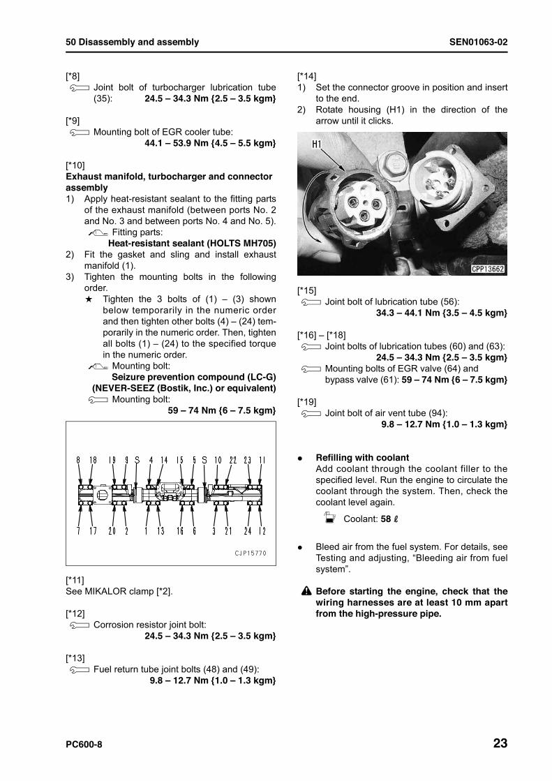
order.a Tighten the 3 bolts of (1) – (3) shown
below temporarily in the numeric orderand then tighten other bolts (4) – (24) tem-porarily in the numeric order. Then, tightenall bolts (1) – (24) to the specified torquein the numeric order.
2 Mounting bolt: Seizure prevention compound (LC-G)
(NEVER-SEEZ (Bostik, Inc.) or equivalent)3 Mounting bolt:
59 – 74 Nm {6 – 7.5 kgm}
[*11]See MIKALOR clamp [*2].
[*12]3 Corrosion resistor joint bolt:
24.5 – 34.3 Nm {2.5 – 3.5 kgm}
[*13]3 Fuel return tube joint bolts (48) and (49):
9.8 – 12.7 Nm {1.0 – 1.3 kgm}
[*14]1) Set the connector groove in position and insert
to the end.2) Rotate housing (H1) in the direction of the
arrow until it clicks.
[*15]3 Joint bolt of lubrication tube (56):
34.3 – 44.1 Nm {3.5 – 4.5 kgm}
[*16] – [*18]3 Joint bolts of lubrication tubes (60) and (63):
24.5 – 34.3 Nm {2.5 – 3.5 kgm}3 Mounting bolts of EGR valve (64) and
bypass valve (61): 59 – 74 Nm {6 – 7.5 kgm}
[*19]3 Joint bolt of air vent tube (94):
9.8 – 12.7 Nm {1.0 – 1.3 kgm}
q Refilling with coolantAdd coolant through the coolant filler to thespecified level. Run the engine to circulate thecoolant through the system. Then, check thecoolant level again.
5 Coolant: 58 l
q Bleed air from the fuel system. For details, seeTesting and adjusting, “Bleeding air from fuelsystem”.
k Before starting the engine, check that thewiring harnesses are at least 10 mm apartfrom the high-pressure pipe.
SEN01063-02 50 Disassembly and assembly
24 PC600-8
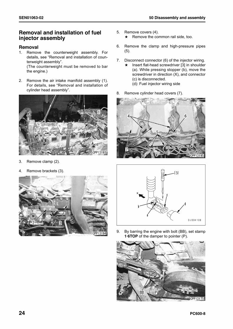
Removal and installation of fuel injector assembly 1Removal1. Remove the counterweight assembly. For
details, see “Removal and installation of coun-terweight assembly”.(The counterweight must be removed to barthe engine.)
2. Remove the air intake manifold assembly (1).For details, see “Removal and installation ofcylinder head assembly”.
3. Remove clamp (2).
4. Remove brackets (3).
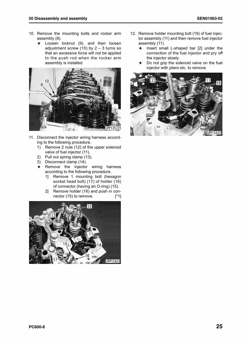
5. Remove covers (4).a Remove the common rail side, too.
6. Remove the clamp and high-pressure pipes(5).
7. Disconnect connector (6) of the injector wiring.a Insert flat-head screwdriver [3] in shoulder
(a). While pressing stopper (b), move thescrewdriver in direction (X), and connector(c) is disconnected.(d): Fuel injector wiring side
8. Remove cylinder head covers (7).
9. By barring the engine with bolt (BB), set stamp1·6TOP of the damper to pointer (P).
50 Disassembly and assembly SEN01063-02
PC600-8 25
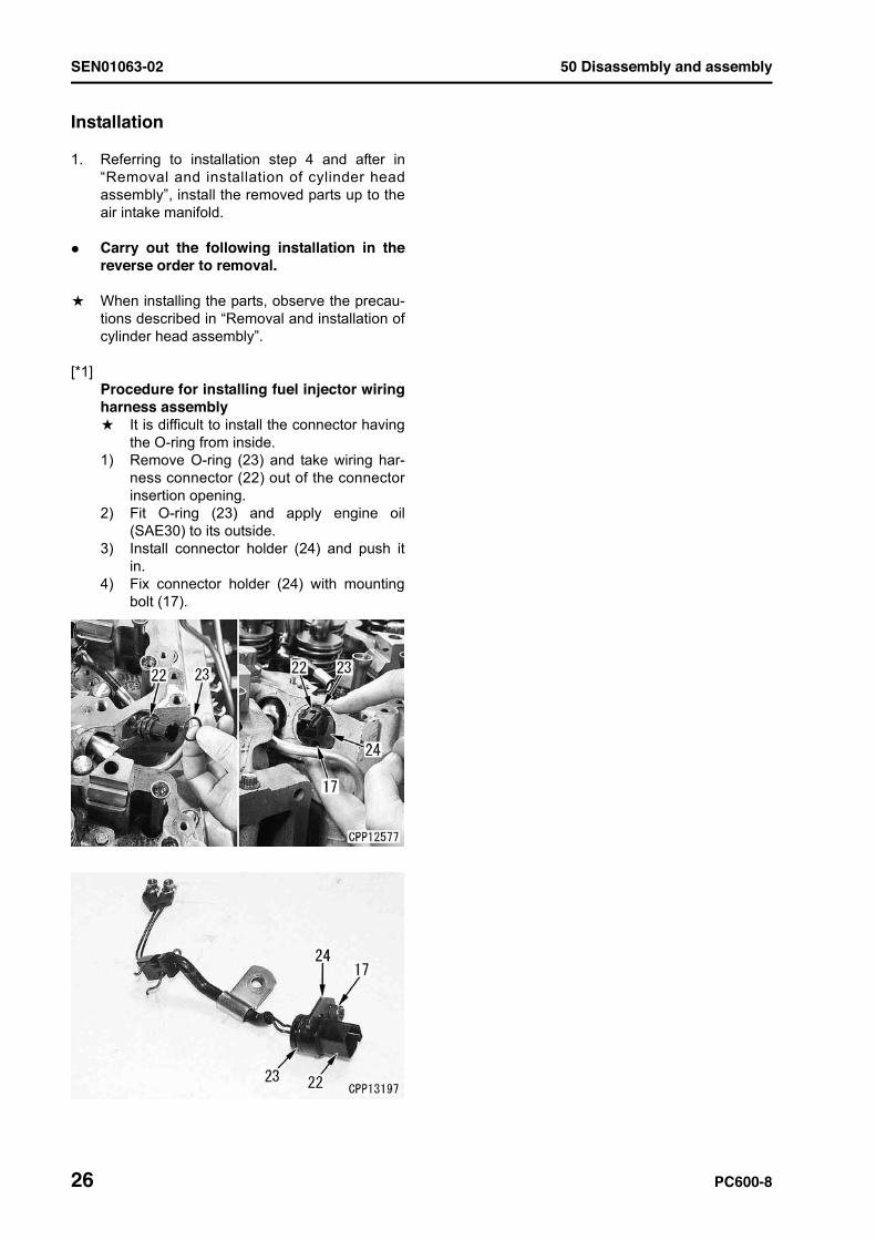
10. Remove the mounting bolts and rocker armassembly (8).a Loosen locknut (9), and then loosen
adjustment screw (10) by 2 – 3 turns sothat an excessive force will not be appliedto the push rod when the rocker armassembly is installed.
11. Disconnect the injector wiring harness accord-ing to the following procedure.1) Remove 2 nuts (12) of the upper solenoid
valve of fuel injector (11).2) Pull out spring clamp (13).3) Disconnect clamp (14).a Remove the injector wiring harness
according to the following procedure.1] Remove 1 mounting bolt (hexagon
socket head bolt) (17) of holder (16)of connector (having an O-ring) (15).
2] Remove holder (16) and push in con-nector (15) to remove. [*1]
12. Remove holder mounting bolt (19) of fuel injec-tor assembly (11) and then remove fuel injectorassembly (11).a Insert small L-shaped bar [2] under the
connection of the fuel injector and pry offthe injector slowly.
a Do not grip the solenoid valve on the fuelinjector with pliers etc. to remove.
SEN01063-02 50 Disassembly and assembly
26 PC600-8
Installation
1. Referring to installation step 4 and after in“Removal and installation of cylinder headassembly”, install the removed parts up to theair intake manifold.
q Carry out the following installation in thereverse order to removal.
a When installing the parts, observe the precau-tions described in “Removal and installation ofcylinder head assembly”.
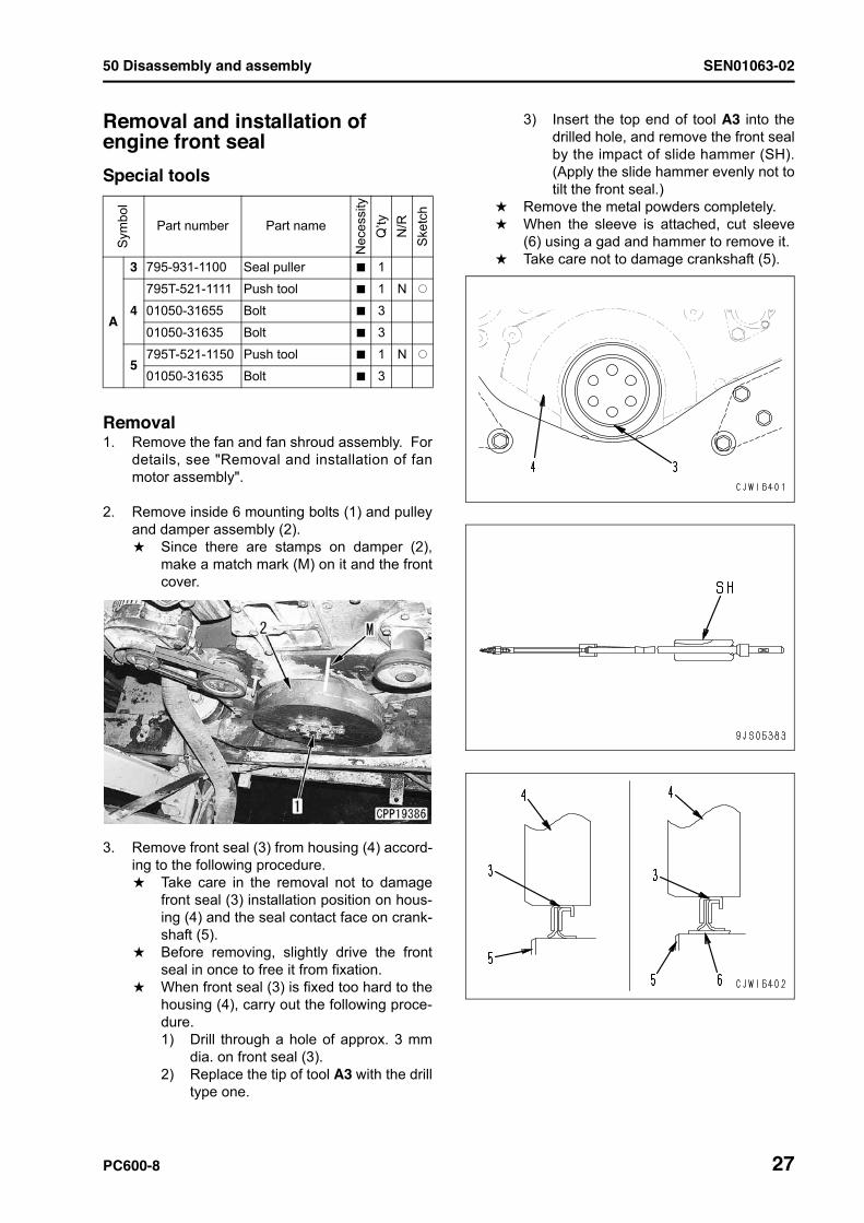
[*1]Procedure for installing fuel injector wiringharness assemblya It is difficult to install the connector having
the O-ring from inside.1) Remove O-ring (23) and take wiring har-
ness connector (22) out of the connectorinsertion opening.
2) Fit O-ring (23) and apply engine oil(SAE30) to its outside.
3) Install connector holder (24) and push itin.
4) Fix connector holder (24) with mountingbolt (17).
50 Disassembly and assembly SEN01063-02
PC600-8 27
Removal and installation of engine front seal 1Special tools
Removal1. Remove the fan and fan shroud assembly. For
details, see "Removal and installation of fanmotor assembly".
2. Remove inside 6 mounting bolts (1) and pulleyand damper assembly (2).a Since there are stamps on damper (2),
make a match mark (M) on it and the frontcover.
3. Remove front seal (3) from housing (4) accord-ing to the following procedure.a Take care in the removal not to damage
front seal (3) installation position on hous-ing (4) and the seal contact face on crank-shaft (5).
a Before removing, slightly drive the frontseal in once to free it from fixation.
a When front seal (3) is fixed too hard to thehousing (4), carry out the following proce-dure.1) Drill through a hole of approx. 3 mm
dia. on front seal (3).2) Replace the tip of tool A3 with the drill
type one.
3) Insert the top end of tool A3 into thedrilled hole, and remove the front sealby the impact of slide hammer (SH).(Apply the slide hammer evenly not totilt the front seal.)
a Remove the metal powders completely.a When the sleeve is attached, cut sleeve
(6) using a gad and hammer to remove it.a Take care not to damage crankshaft (5).
Sym
bol
Part number Part name
Nec
essi
tyQ
’tyN
/RS
ketc
h
A
3 795-931-1100 Seal puller t 1
4795T-521-1111 Push tool t 1 N Q
01050-31655 Bolt t 3
01050-31635 Bolt t 3
5795T-521-1150 Push tool t 1 N Q
01050-31635 Bolt t 3
SEN01063-02 50 Disassembly and assembly
28 PC600-8
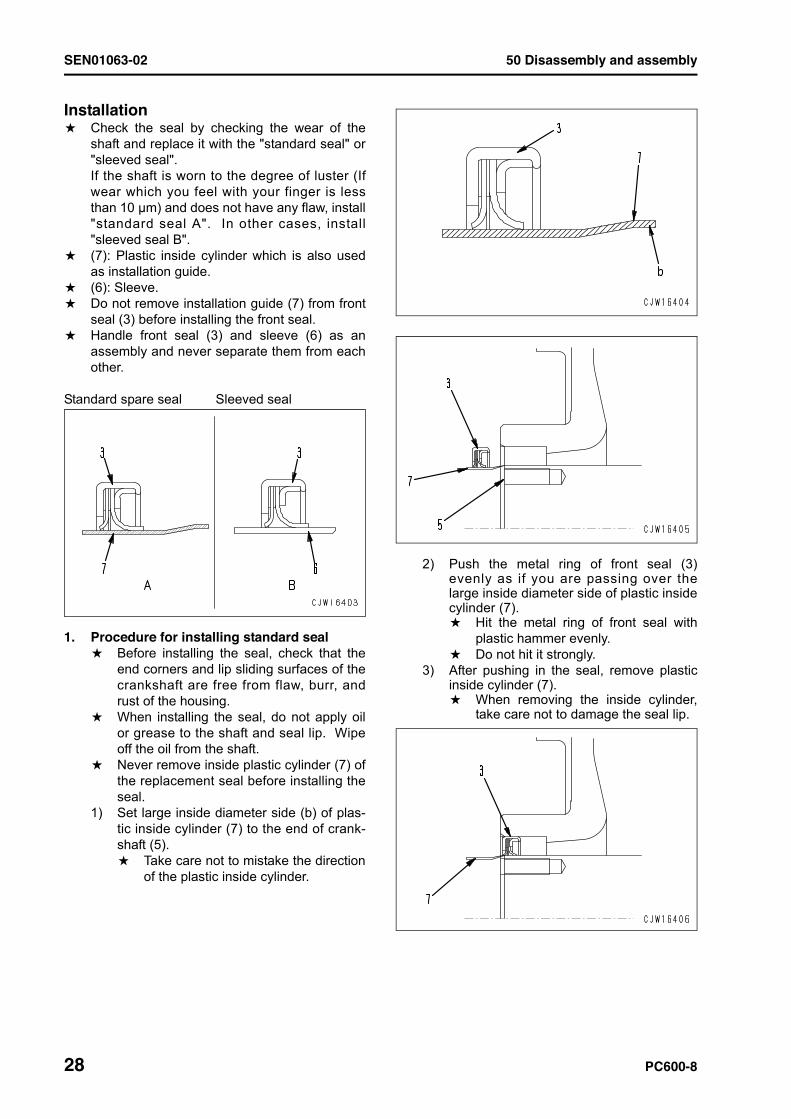
Installationa Check the seal by checking the wear of the
shaft and replace it with the "standard seal" or"sleeved seal".If the shaft is worn to the degree of luster (Ifwear which you feel with your finger is lessthan 10 mm) and does not have any flaw, install"standard seal A". In other cases, install"sleeved seal B".
a (7): Plastic inside cylinder which is also usedas installation guide.
a (6): Sleeve.a Do not remove installation guide (7) from front
seal (3) before installing the front seal.a Handle front seal (3) and sleeve (6) as an
assembly and never separate them from eachother.
Standard spare seal Sleeved seal
1. Procedure for installing standard seala Before installing the seal, check that the
end corners and lip sliding surfaces of thecrankshaft are free from flaw, burr, andrust of the housing.
a When installing the seal, do not apply oilor grease to the shaft and seal lip. Wipeoff the oil from the shaft.
a Never remove inside plastic cylinder (7) ofthe replacement seal before installing theseal.
1) Set large inside diameter side (b) of plas-tic inside cylinder (7) to the end of crank-shaft (5).a Take care not to mistake the direction
of the plastic inside cylinder.
2) Push the metal ring of front seal (3)evenly as if you are passing over thelarge inside diameter side of plastic insidecylinder (7).a Hit the metal ring of front seal with
plastic hammer evenly.a Do not hit it strongly.
3) After pushing in the seal, remove plasticinside cylinder (7).a When removing the inside cylinder,
take care not to damage the seal lip.
50 Disassembly and assembly SEN01063-02
PC600-8 29
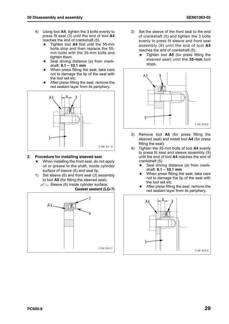
4) Using tool A4, tighten the 3 bolts evenly topress fit seal (3) until the end of tool A4reaches the end of crankshaft (5).a Tighten tool A4 first until the 55-mm
bolts stop and then replace the 55-mm bolts with the 35-mm bolts andtighten them.
a Seal driving distance (a) from crank-shaft: 9.1 – 10.1 mm
a When press fitting the seal, take carenot to damage the lip of the seal withthe tool set etc.
a After press fitting the seal, remove thered sealant layer from its periphery.
2. Procedure for installing sleeved seala When installing the front seal, do not apply
oil or grease to the shaft, inside cylindersurface of sleeve (6) and seal lip.
1) Set sleeve (6) and front seal (3) assemblyto tool A5 (for fitting the sleeved seal).2 Sleeve (6) inside cylinder surface:
Gasket sealant (LG-7)
2) Set the sleeve of the front seal to the endof crankshaft (5) and tighten the 3 boltsevenly to press fit sleeve and front sealassembly (9) until the end of tool A5reaches the end of crankshaft (5).a Tighten tool A5 (for press fitting the
sleeved seal) until the 35-mm boltstops.
3) Remove tool A5 (for press fitting thesleeved seal) and install tool A4 (for pressfitting the seal).
4) Tighten the 35-mm bolts of tool A4 evenlyto press fit seal and sleeve assembly (9)until the end of tool A4 reaches the end ofcrankshaft (5).a Seal driving distance (a) from crank-
shaft: 9.1 – 10.1 mma When press fitting the seal, take care
not to damage the lip of the seal withthe tool set etc.
a After press fitting the seal, remove thered sealant layer from its periphery.
SEN01063-02 50 Disassembly and assembly
30 PC600-8
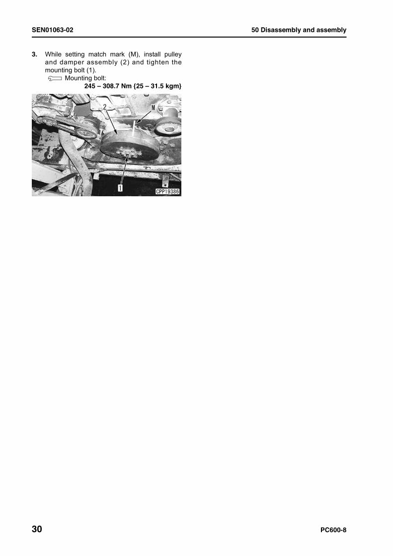
3. While setting match mark (M), install pulleyand damper assembly (2) and tighten themounting bolt (1).3 Mounting bolt:
245 – 308.7 Nm {25 – 31.5 kgm}
50 Disassembly and assembly SEN01063-02
PC600-8 31
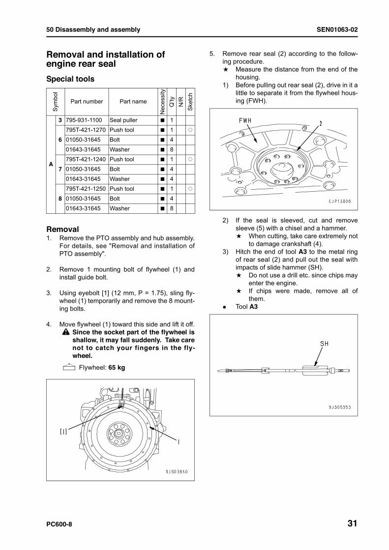
Removal and installation of engine rear seal 1Special tools
Removal1. Remove the PTO assembly and hub assembly.
For details, see "Removal and installation ofPTO assembly".
2. Remove 1 mounting bolt of flywheel (1) andinstall guide bolt.
3. Using eyebolt [1] (12 mm, P = 1.75), sling fly-wheel (1) temporarily and remove the 8 mount-ing bolts.
4. Move flywheel (1) toward this side and lift it off.k Since the socket part of the flywheel is
shallow, it may fall suddenly. Take carenot to catch your fingers in the fly-wheel.
4 Flywheel: 65 kg
5. Remove rear seal (2) according to the follow-ing procedure.a Measure the distance from the end of the
housing.1) Before pulling out rear seal (2), drive in it a
little to separate it from the flywheel hous-ing (FWH).
2) If the seal is sleeved, cut and removesleeve (5) with a chisel and a hammer.a When cutting, take care extremely not
to damage crankshaft (4).3) Hitch the end of tool A3 to the metal ring
of rear seal (2) and pull out the seal withimpacts of slide hammer (SH).a Do not use a drill etc. since chips may
enter the engine.a If chips were made, remove all of
them.q Tool A3
Sym
bol
Part number Part name
Nec
essi
tyQ
’tyN
/RS
ketc
h
A
3 795-931-1100 Seal puller t 1
6795T-421-1270 Push tool t 1 Q
01050-31645 Bolt t 4
01643-31645 Washer t 8
7795T-421-1240 Push tool t 1 Q
01050-31645 Bolt t 4
01643-31645 Washer t 4
8795T-421-1250 Push tool t 1 Q
01050-31645 Bolt t 4
01643-31645 Washer t 8
SEN01063-02 50 Disassembly and assembly
32 PC600-8
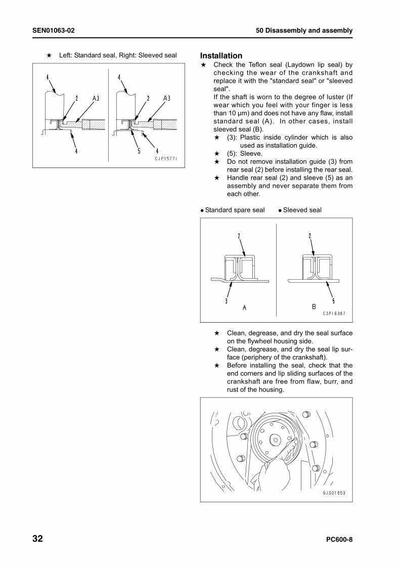
a Left: Standard seal, Right: Sleeved seal Installationa Check the Teflon seal (Laydown lip seal) by
checking the wear of the crankshaft andreplace it with the "standard seal" or "sleevedseal".If the shaft is worn to the degree of luster (Ifwear which you feel with your finger is lessthan 10 mm) and does not have any flaw, installstandard seal (A). In other cases, installsleeved seal (B).a (3): Plastic inside cylinder which is also
used as installation guide.a (5): Sleeve.a Do not remove installation guide (3) from
rear seal (2) before installing the rear seal.a Handle rear seal (2) and sleeve (5) as an
assembly and never separate them fromeach other.
q Standard spare seal q Sleeved seal
a Clean, degrease, and dry the seal surfaceon the flywheel housing side.
a Clean, degrease, and dry the seal lip sur-face (periphery of the crankshaft).
a Before installing the seal, check that theend corners and lip sliding surfaces of thecrankshaft are free from flaw, burr, andrust of the housing.
50 Disassembly and assembly SEN01063-02
PC600-8 33
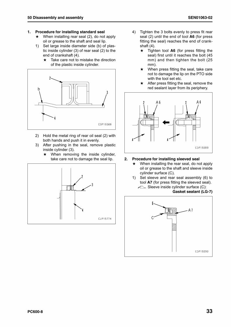
1. Procedure for installing standard seala When installing rear seal (2), do not apply
oil or grease to the shaft and seal lip.1) Set large inside diameter side (b) of plas-
tic inside cylinder (3) of rear seal (2) to theend of crankshaft (4).a Take care not to mistake the direction
of the plastic inside cylinder.
2) Hold the metal ring of rear oil seal (2) withboth hands and push it in evenly.
3) After pushing in the seal, remove plasticinside cylinder (3).a When removing the inside cylinder,
take care not to damage the seal lip.
4) Tighten the 3 bolts evenly to press fit rearseal (2) until the end of tool A6 (for pressfitting the seal) reaches the end of crank-shaft (4).a Tighten tool A6 (for press fitting the
seal) first until it reaches the bolt (45mm) and then tighten the bolt (25mm).
a When press fitting the seal, take carenot to damage the lip on the PTO sidewith the tool set etc.
a After press fitting the seal, remove thered sealant layer from its periphery.
2. Procedure for installing sleeved seala When installing the rear seal, do not apply
oil or grease to the shaft and sleeve insidecylinder surface (C).
1) Set sleeve and rear seal assembly (6) totool A7 (for press fitting the sleeved seal).2 Sleeve inside cylinder surface (C):
Gasket sealant (LG-7)
SEN01063-02 50 Disassembly and assembly
34 PC600-8
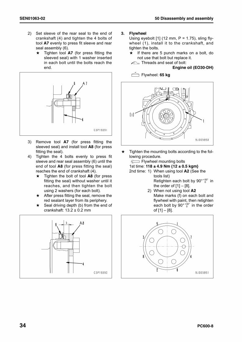
2) Set sleeve of the rear seal to the end ofcrankshaft (4) and tighten the 4 bolts oftool A7 evenly to press fit sleeve and rearseal assembly (6).a Tighten tool A7 (for press fitting the
sleeved seal) with 1 washer insertedin each bolt until the bolts reach theend.
3) Remove tool A7 (for press fitting thesleeved seal) and install tool A8 (for pressfitting the seal).
4) Tighten the 4 bolts evenly to press fitsleeve and rear seal assembly (6) until theend of tool A8 (for press fitting the seal)reaches the end of crankshaft (4).a Tighten the bolt of tool A8 (for press
fitting the seal) without washer until itreaches, and then tighten the boltusing 2 washers (for each bolt).
a After press fitting the seal, remove thered sealant layer from its periphery.
a Seal driving depth (b) from the end ofcrankshaft: 13.2 ± 0.2 mm
3. FlywheelUsing eyebolt [1] (12 mm, P = 1.75), sling fly-wheel (1), install it to the crankshaft, andtighten the bolts.a If there are 5 punch marks on a bolt, do
not use that bolt but replace it.2 Threads and seat of bolt:
Engine oil (EO30-DH)
4 Flywheel: 65 kg
a Tighten the mounting bolts according to the fol-lowing procedure.3 Flywheel mounting bolts
1st time: 118 ± 4.9 Nm {12 ± 0.5 kgm}2nd time: 1) When using tool A2 (See the
tools list)Retighten each bolt by 90° inthe order of [1] – [8].
2) When not using tool A2Make marks (f) on each bolt andflywheel with paint, then retighteneach bolt by 90° in the orderof [1] – [8].
+30°+0
+30°+0
50 Disassembly and assembly SEN01063-02
PC600-8 35
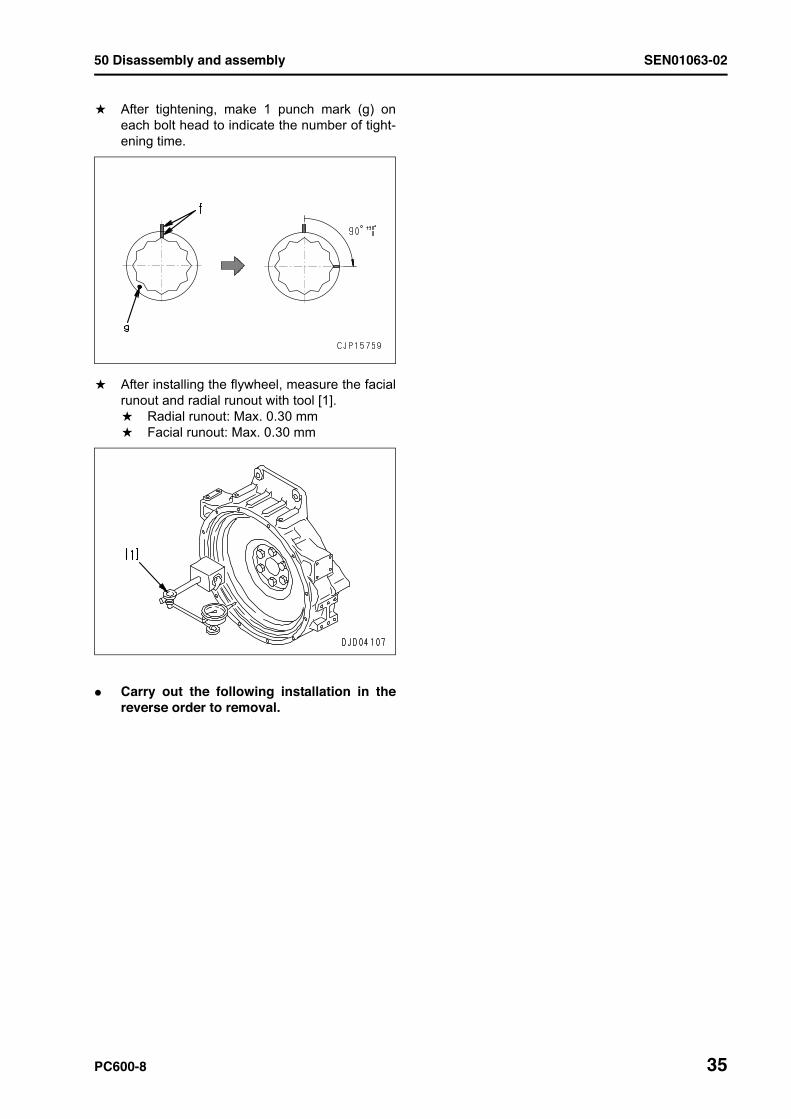
a After tightening, make 1 punch mark (g) oneach bolt head to indicate the number of tight-ening time.
a After installing the flywheel, measure the facialrunout and radial runout with tool [1].a Radial runout: Max. 0.30 mma Facial runout: Max. 0.30 mm
q Carry out the following installation in thereverse order to removal.
36
SEN01063-02
PC600, 600LC-8 Hydraulic excavator
Form No. SEN01063-02
© 2009 KOMATSUAll Rights ReservedPrinted in Japan 01-09 (01)