Embed Size (px)
Citation preview


1.1 DOCUMENTATION CROSS REFERENCE
502913 Orbit3 System Manual Details on installation and electrical requirements.
502914 Orbit3 Module Manual Details on installation and electrical requirements.
502920 Orbit3 Catalogue Describes the Orbit3 system and provides details of the products including specifications and dimensions
1.2 TRADEMARKS AND COPYRIGHTS
Information in this document is subject to change without notice.No part of this document may be reproduced or transmitted in any form or by means, electronic or mechanical, for any purpose, without the express permission of Solartron Metrology.
© 2010 Solartron Metrology Ltd. All rights reserved.
Microsoft®, Windows®XP, Windows®Vista, Windows®7, Excel®, VBA and VB are registered trademarks or trademarks of Microsoft Corporation in the United States and/or other countries.Delphi® and C++ Builder® are registered trademarks of Embarcadero.All other brand names, product names or trademarks belong to their respective holders.
Orbit® is a registered trademark of Solartron Metrology Ltd
1.3 CONTACT INFORMATIONFor updated information, troubleshooting guide and to see our full range of products, visit our website:http://www.solartronmetrology.com
Software Manual Issue 1 Page 2 of 182

2 TABLE OF CONTENTS1.1 Documentation Cross Reference.....................................................................................21.2 Trademarks and Copyrights.............................................................................................21.3 Contact Information..........................................................................................................2
2 TABLE OF CONTENTS.....................................................................................................3
3 INTRODUCTION...............................................................................................................103.1 Scope.............................................................................................................................103.2 Navigating this document...............................................................................................113.3 Terms and Abbreviations...............................................................................................11
4 SOFTWARE INTERFACING TO ORBIT.........................................................................124.1 Introduction....................................................................................................................124.2 Orbit COM Library..........................................................................................................124.3 Orbit COM Code Examples...........................................................................................12
4.3.1 COM Examples.................................................................................................................................124.3.2 Excel Examples.................................................................................................................................13
4.3.2.1 Standard Mode Example............................................................................................................134.3.2.2 Dynamic Examples.....................................................................................................................13
4.4 Orbit DLL........................................................................................................................134.4.1 DLL Examples...................................................................................................................................14
4.5 Using Orbit without Windows.........................................................................................144.6 Orbit Troubleshooting....................................................................................................14
5 ORBIT UTILITY PROGRAMS..........................................................................................145.1 Orbit COM Test..............................................................................................................145.2 Orbit Registration ..........................................................................................................155.3 Orbit Demonstrator........................................................................................................155.4 Orbit SW Report.............................................................................................................155.5 Orbit3 Network Power Calculator..................................................................................155.6 Orbit Support Pack for Excel..........................................................................................15
6 POWER UP CONDITIONS...............................................................................................16
7 NEW FEATURES AND COMMANDS WITH ORBIT3.....................................................177.1 HotSwap.........................................................................................................................17
7.1.1 Hot Swap Extra Modes......................................................................................................................187.1.1.1 FindHotswapped........................................................................................................................187.1.1.2 ResetTCons...............................................................................................................................18
7.2 Ping................................................................................................................................187.3 ReadCurrentInUOM.......................................................................................................19
8 ORBIT MEASUREMENT MODES...................................................................................208.1 Standard Measurement Mode.......................................................................................20
8.1.1 COM Library Method.........................................................................................................................208.1.2 DLL Method.......................................................................................................................................208.1.3 COM Library Versus DLL...................................................................................................................208.1.4 Difference Mode ...............................................................................................................................208.1.5 Programmable Resolution.................................................................................................................218.1.6 Programmable Electrical Measurement Bandwidth...........................................................................218.1.7 Programmable Baud Rate.................................................................................................................22
8.2 Buffered Mode................................................................................................................238.2.1 Introduction to Buffered Mode...........................................................................................................23
Software Manual Issue 1 Page 3 of 182

8.2.2 Synchronized Mode (Buffered)..........................................................................................................238.2.3 Sample Mode Buffered......................................................................................................................238.2.4 Sample Mode Buffered - Using EIM..................................................................................................24
8.3 Dynamic Mode...............................................................................................................258.3.1 Introduction to Dynamic Mode...........................................................................................................258.3.2 Why Use Dynamic Mode...................................................................................................................258.3.3 Alternatives to Dynamic Mode...........................................................................................................258.3.4 Resolution in Dynamic Mode.............................................................................................................268.3.5 Collection Rate..................................................................................................................................268.3.6 Dynamic Mode System Constraints...................................................................................................278.3.7 Dynamic Collection in Multicard Mode...............................................................................................28
8.3.7.1 Software Operation for Multicard Use........................................................................................288.3.8 Hardware Requirements for Dynamic Mode......................................................................................288.3.9 Software Requirements for Dynamic Mode.......................................................................................298.3.10 Hints and Tips on Using Dynamic Mode..........................................................................................298.3.11 Dynamic Schemes...........................................................................................................................30
8.3.11.1 Dynamic Scheme 1 - Network Card as the Sync source..........................................................308.3.11.2 Dynamic Scheme 2 - Encoder as the Sync source..................................................................31
8.3.12 Examples of Using Dynamic Mode..................................................................................................328.3.12.1 Dynamic Mode Example Using Time Triggered Readings, .....................................................328.3.12.2 Dynamic Mode Example Using Angle Triggered Readings......................................................32
8.3.13 Dynamic with EIM used as a Sync Source......................................................................................328.3.13.1 Calculating the number of Sync pulses required when using EIM as sync source...................328.3.13.2 Sync Pulse Rate when using EIM as a Sync source................................................................338.3.13.3 Speed Calculations when using an EIM as a Sync source.......................................................34
9 ORBIT COM LIBRARY....................................................................................................359.1 Introduction....................................................................................................................359.2 Target Languages..........................................................................................................359.3 Examples.......................................................................................................................369.4 COM Library Overview...................................................................................................36
9.4.1 Primary COM Object.........................................................................................................................379.4.2 Networks Manager Object.................................................................................................................379.4.3 Network Object..................................................................................................................................379.4.4 Modules Manager Object...................................................................................................................379.4.5 Module Object...................................................................................................................................37
9.5 Importing the Orbit COM Library....................................................................................389.5.1 Microsoft VBA (Visual Basic for Applications)....................................................................................399.5.2 Microsoft Visual Basic.......................................................................................................................419.5.3 Microsoft Visual C/C++......................................................................................................................439.5.4 Delphi................................................................................................................................................479.5.5 C++ Builder........................................................................................................................................499.5.6 C Builder - RAD Studio 2009.............................................................................................................519.5.7 Microsoft Visual C# (2008 Express Edition).......................................................................................55
9.6 Using the Orbit COM Library..........................................................................................569.6.1 Microsoft VBA (Visual Basic for Applications)....................................................................................569.6.2 C Builder - RAD Studio 2009.............................................................................................................56
10 ORBITSERVER OBJECTS............................................................................................5710.1 Methods.......................................................................................................................57
10.1.1 AbortCollection................................................................................................................................5710.1.2 Connect...........................................................................................................................................5710.1.3 Disconnect.......................................................................................................................................5710.1.4 StartCollection.................................................................................................................................5710.1.5 StopCollection.................................................................................................................................58
10.2 Properties.....................................................................................................................5810.2.1 CollectionDone................................................................................................................................5810.2.2 COMVersion....................................................................................................................................5810.2.3 Connected.......................................................................................................................................5810.2.4 IFVersionNumber............................................................................................................................5810.2.5 IFVersionStr.....................................................................................................................................5810.2.6 Networks..........................................................................................................................................58
Software Manual Issue 1 Page 4 of 182
10.2.7 NumNetworks..................................................................................................................................5810.2.8 SoundOn.........................................................................................................................................58
11 ORBITNETWORKS OBJECTS......................................................................................5911.1 Methods.......................................................................................................................5911.2 Properties.....................................................................................................................59
11.2.1 Count...............................................................................................................................................5911.2.2 Item.................................................................................................................................................59
12 ORBITNETWORK OBJECTS........................................................................................5912.1 Methods.......................................................................................................................60
12.1.1 ApplyRemap....................................................................................................................................6012.1.2 ClearBuffers.....................................................................................................................................6012.1.3 FindHotswapped..............................................................................................................................6012.1.4 Load................................................................................................................................................6012.1.5 Ping.................................................................................................................................................6012.1.6 PrepareForCollection.......................................................................................................................6012.1.7 ReadLiveData..................................................................................................................................6012.1.8 Reset...............................................................................................................................................6112.1.9 Save................................................................................................................................................6112.1.10 StartBufferedMode........................................................................................................................6112.1.11 StartDifferenceMode......................................................................................................................6112.1.12 StopBufferedMode.........................................................................................................................6112.1.13 StopDifferenceMode......................................................................................................................61
12.2 Properties.....................................................................................................................6212.2.1 CollectionMode................................................................................................................................6212.2.2 CollectionNumModules....................................................................................................................6212.2.3 CollectionRate.................................................................................................................................6212.2.4 ComSpeed.......................................................................................................................................6212.2.5 DynamicCapable.............................................................................................................................6212.2.6 HighSpeedCapable.........................................................................................................................6212.2.7 MasterStatus...................................................................................................................................6212.2.8 NetDescription.................................................................................................................................6212.2.9 NetName.........................................................................................................................................6212.2.10 NetType.........................................................................................................................................6312.2.11 NumModulesOnNW.......................................................................................................................63
13 ORBITMODULES OBJECTS.........................................................................................6413.1 Methods.......................................................................................................................64
13.1.1 Add..................................................................................................................................................6413.1.2 Remove...........................................................................................................................................6413.1.3 Notify...............................................................................................................................................6413.1.4 StopNotify........................................................................................................................................6413.1.5 NotifyAndAdd...................................................................................................................................6513.1.6 ResetTCons.....................................................................................................................................65
13.2 Properties.....................................................................................................................6513.2.1 Item.................................................................................................................................................6513.2.2 Count...............................................................................................................................................65
14 ORBITMODULE OBJECTS...........................................................................................6514.1 Methods.......................................................................................................................65
14.1.1 ChangeDirection..............................................................................................................................6514.1.2 ClearBufferedMode.........................................................................................................................6514.1.3 ClearDifferenceMode.......................................................................................................................6614.1.4 GetRefMark.....................................................................................................................................6614.1.5 Getstatus.........................................................................................................................................6614.1.6 ReadBuffer......................................................................................................................................6614.1.7 ReadCollected.................................................................................................................................6614.1.8 ReadCurrent....................................................................................................................................6714.1.9 ReadDifference................................................................................................................................6714.1.10 RestoreDefaults.............................................................................................................................67
Software Manual Issue 1 Page 5 of 182

14.1.11 SetBufferedMode...........................................................................................................................6714.1.12 SetDifferenceMode........................................................................................................................6714.1.13 SetPreset.......................................................................................................................................67
14.2 Properties.....................................................................................................................6814.2.1 BuffNumReadings...........................................................................................................................6814.2.2 DeviceType......................................................................................................................................6814.2.3 DiffMin.............................................................................................................................................6814.2.4 DiffMax............................................................................................................................................6814.2.5 DiffNumReadings............................................................................................................................6814.2.6 DiffSum............................................................................................................................................6814.2.7 Direction..........................................................................................................................................6814.2.8 Holdoff.............................................................................................................................................6814.2.9 HWType...........................................................................................................................................6914.2.10 InRange.........................................................................................................................................6914.2.11 IPType...........................................................................................................................................6914.2.12 ModuleError...................................................................................................................................6914.2.13 ModuleID.......................................................................................................................................6914.2.14 BaseModuleID...............................................................................................................................6914.2.15 ModuleInfo.....................................................................................................................................6914.2.16 ModuleName.................................................................................................................................6914.2.17 ModuleStatus.................................................................................................................................6914.2.18 ModuleType...................................................................................................................................6914.2.19 NotifyInProgress............................................................................................................................6914.2.20 QuadMode.....................................................................................................................................7014.2.21 ReadCurrentInUOM.......................................................................................................................7014.2.22 ReadingAveraging.........................................................................................................................7014.2.23 ReadingResolution........................................................................................................................7014.2.24 RefAction.......................................................................................................................................7014.2.25 ReMapAddress..............................................................................................................................7014.2.26 Scale..............................................................................................................................................7114.2.27 Stroke............................................................................................................................................7114.2.28 SWVersion.....................................................................................................................................7114.2.29 TxSample......................................................................................................................................7114.2.30 TxSync...........................................................................................................................................7114.2.31 UnitsOfMeasure.............................................................................................................................71
15 MODULE COMMANDS..................................................................................................7215.1 Command Types..........................................................................................................7215.2 Command Summary....................................................................................................72
15.2.1 Low Level Syntax Details.................................................................................................................7415.3 OrbitSetaddr.................................................................................................................7415.4 OrbitNotify....................................................................................................................7615.5 OrbitPing......................................................................................................................7815.6 OrbitIdentify..................................................................................................................7915.7 OrbitGetinfo..................................................................................................................8115.8 OrbitGetstatus..............................................................................................................84
15.8.1 Digital Probe - Status Format..........................................................................................................8515.8.2 Linear Encoder - Status Format......................................................................................................8615.8.3 Encoder Input Module (EIM) - Status Format..................................................................................8715.8.4 Digimatic Interface Module (DIM) – Status Format..........................................................................87
15.8.4.1 Status Word Examples.............................................................................................................8815.9 OrbitSetmode...............................................................................................................89
15.9.1.1 OrbitSetmode & DIM................................................................................................................9515.10 OrbitControl................................................................................................................95
15.10.1 OrbitControl & DIM........................................................................................................................9615.11 OrbitRead1.................................................................................................................9715.12 OrbitReadbuffer1.......................................................................................................9915.13 OrbitRead2...............................................................................................................10115.14 OrbitClr.....................................................................................................................10315.15 OrbitRst....................................................................................................................10415.16 OrbitDifference.........................................................................................................106
Software Manual Issue 1 Page 6 of 182

15.17 OrbitStartdiff.............................................................................................................10715.18 OrbitStopdiff.............................................................................................................10915.19 OrbitReaddiff1..........................................................................................................11015.20 OrbitReaddiff2..........................................................................................................11215.21 OrbitPreset...............................................................................................................11315.22 OrbitRefmark............................................................................................................11515.23 OrbitDirection...........................................................................................................11615.24 OrbitTconClr.............................................................................................................11815.25 Legacy Commands..................................................................................................119
15.25.1 OrbitAcquire.................................................................................................................................11915.25.2 OrbitTrigger.................................................................................................................................12015.25.3 OrbitReadia.................................................................................................................................120
16 ORBIT DLL - CONTROLLER COMMANDS................................................................12216.1 General Controller Commands..................................................................................122
16.1.1 ConnectToOrbitNetworks..............................................................................................................12216.1.2 DisconnectFromOrbitNetworks .....................................................................................................12316.1.3 GetOrbitNetworkNameAndType ...................................................................................................12316.1.4 ReportOrbitProbeAssignment .......................................................................................................12316.1.5 ReportOrbitModuleAssignment .....................................................................................................12316.1.6 ReportOrbitInterfaceVersion..........................................................................................................12316.1.7 ReportOrbitError ...........................................................................................................................12316.1.8 SetupNetworkController ................................................................................................................12416.1.9 ChangeNetworkSpeed ..................................................................................................................12416.1.10 RequestDataStorage ..................................................................................................................12416.1.11 FreeDataStorage ........................................................................................................................12416.1.12 InitialiseCallbacks .......................................................................................................................12416.1.13 GetDynamicLiveData ..................................................................................................................12416.1.14 GetCollectedReading ..................................................................................................................125
17 CONTROLLER SPECIFICS.........................................................................................12617.1 RS232 Controller (RS232IM).....................................................................................126
17.1.1 Introduction....................................................................................................................................12617.1.2 RS232IM Default Baud Rate.........................................................................................................12617.1.3 Operation.......................................................................................................................................12617.1.4 Command Order............................................................................................................................12617.1.5 RS232IM Command Format and Command Byte.........................................................................127
17.1.5.1 Command Byte 0 - Send Orbit message, no reply (Broadcast)..............................................12717.1.5.2 Command Byte 2 - Send Orbit message, wait for reply (Addressed).....................................12717.1.5.3 Command Byte 14 - Send Orbit message, wait for variable length reply (Addressed)...........128
17.1.6 RS232IM Specific Commands.......................................................................................................12817.1.6.1 Command Byte 10 - Change Baud Rate & Handshaking.......................................................12817.1.6.2 Command Byte 16 - Set RS232IM Orbit interface to ‘Idle’.....................................................130
17.1.7 RS232IM Error Codes...................................................................................................................13117.2 RS485 Controller (RS485IM).....................................................................................131
18 MODULE SPECIFICS..................................................................................................13218.1 Encoder Input Module (EIM)......................................................................................132
18.1.1 Introduction....................................................................................................................................13218.1.2 EIM & OrbitSetmode (Modes 70,71, 75 - 78)................................................................................13218.1.3 EIM & Dynamic Mode....................................................................................................................13218.1.4 EIM & Buffered Mode....................................................................................................................13218.1.5 EIM & Reference Mark..................................................................................................................132
18.2 Digital Input Output Module (DIOM)..........................................................................13418.2.1 Introduction....................................................................................................................................13418.2.2 Read Inputs...................................................................................................................................13418.2.3 Set Outputs....................................................................................................................................134
18.3 Digimatic Interface Module (DIM)..............................................................................13518.3.1 Introduction....................................................................................................................................13518.3.2 Using the Digimatic Interface Module (DIM)..................................................................................135
Software Manual Issue 1 Page 7 of 182

18.3.2.1 DIM & OrbitRead2 command:................................................................................................13518.3.3 Changing the Mode of Operation...................................................................................................13618.3.4 Reading the DIM status.................................................................................................................136
18.4 Linear Encoder...........................................................................................................13618.4.1 Introduction....................................................................................................................................13618.4.2 Linear Encoder & Reference Mark................................................................................................136
18.4.2.1 Reference Mark using the Orbit COM....................................................................................13618.4.2.2 Reference Mark using the Orbit DLL......................................................................................137
19 ORBIT ERROR CODES AND ERROR HANDLING....................................................13819.1 General......................................................................................................................13819.2 Handling Errors..........................................................................................................138
19.2.1 Error Handling When Using DLL...................................................................................................13819.2.2 Error Handling When Using COM..................................................................................................138
19.3 Common Errors..........................................................................................................13919.3.1 No Error.........................................................................................................................................13919.3.2 Timeout Error.................................................................................................................................13919.3.3 Overspeed Error............................................................................................................................13919.3.4 Address already set.......................................................................................................................139
19.4 Error Codes From Orbit Modules...............................................................................14019.5 DLL Error Codes........................................................................................................14419.6 Orbit Controller Error Codes......................................................................................145
19.6.1 Specific RS232IM Error Codes......................................................................................................146
20 APPLICATION NOTES & EXAMPLES........................................................................14720.1 COM Programming Techniques and Guidelines.......................................................147
20.1.1 General Guidelines........................................................................................................................14720.1.1.1 Error handling.........................................................................................................................147
20.1.2 Dynamic Collection Guidelines......................................................................................................14820.1.2.1 Steps in Performing a Dynamic Collection.............................................................................14820.1.2.2 Steps in Performing a Dynamic Collection with an EIM triggering readings as a master.......148
20.1.3 Number of modules allowed in Dynamic Mode..............................................................................14920.1.4 Maximum Number of Readings in a Collection..............................................................................14920.1.5 Reading from a subset of connected modules...............................................................................150
20.1.5.1 Valid Data...............................................................................................................................15020.1.5.2 Soft Errors (Module Under or Over Range) ..........................................................................15020.1.5.3 Fatal Errors.............................................................................................................................151
20.1.6 Use of ReadLiveData method .......................................................................................................15220.1.6.1 ReadLiveData Array Map for 1k Data Rate .........................................................................15320.1.6.2 ReadLiveData Array Map for 2k Data Rate............................................................................15320.1.6.3 ReadLiveData Array Map for 4k Data Rate............................................................................154
20.2 Reading an Orbit Module...........................................................................................15520.3 Digimatic Interface Module (DIM) Code Examples....................................................156
20.3.1 Taking a Gauge reading continuously ..........................................................................................15620.3.2 Taking a Gauge reading when ‘DATA’ switch is pressed..............................................................15720.3.3 Taking a Gauge reading when Key is pressed (using OrbitControl (Action=30))...........................158
20.4 DIOM Example...........................................................................................................15920.4.1 Multiple Readings..........................................................................................................................159
20.5 Using the Orbitgetinfo Command..............................................................................16020.5.1 Module Type..................................................................................................................................16020.5.2 Hardware Type..............................................................................................................................16120.5.3 Scale (formerly known as Resolution)...........................................................................................16120.5.4 ModuleInfo.....................................................................................................................................16220.5.5 Converting Readings to Units Of Measure (UOM).........................................................................164
20.5.5.1 UOM example - Digital Probe set to 16 bit mode...................................................................16420.5.5.2 UOM example - Analogue Input Module 4-20mA 18bit mode................................................16520.5.5.3 UOM example - Analogue Input Module +/-10V 14bit mode..................................................165
20.5.6 Method to use Moduleinfo for all module Types............................................................................165
21 APPENDIX A - ENUMERATED TYPES USED BY THE COM LIBRARY..................174
Software Manual Issue 1 Page 8 of 182
22 APPENDIX B - ORBIT NETWORK THROUGHPUT...................................................176
23 APPENDIX C - ORBIT COMPATIBILITY ROADMAP.................................................17723.1 Modules......................................................................................................................178
23.1.1 Orbit3.............................................................................................................................................17823.1.2 Orbit2.............................................................................................................................................17923.1.3 Orbit1.............................................................................................................................................180
23.2 Controllers & Software...............................................................................................18123.2.1 Orbit3.............................................................................................................................................18123.2.2 Orbit2.............................................................................................................................................18123.2.3 Orbit1.............................................................................................................................................181
24 REVISION HISTORY....................................................................................................182
Software Manual Issue 1 Page 9 of 182

3 INTRODUCTION
3.1 SCOPE
The Orbit®3 Measurement System is a modular measurement system that can be put together quickly, easily and is cost effective. It allows different types of sensors to be easily mixed and integrated on a single network independent of sensor technology. In addition to linear probes and linear displacement transducers, third party sensors can easily be integrated, this, combined with programmable input and output modules for interfacing to external equipment makes the Orbit®3 Measurement System a flexible solution for measurement applications.
Typically an Orbit®3 Measurement System will consist of four elements,windows support Measurements Modules with T-Connectors, Measurement System controllers, power supplies and cables. All of which can be obtained from the same supplier thus guaranteeing compatibility and accelerating system integration.
The Orbit®3 Measurement System also includes a range of readouts for stand alone measurement systems these also can be used as a basic interface to a PLC.
This document defines the software protocol of the Orbit®3 Measurement System and provides information and guidance on using the Orbit software drivers.The information is principally for users of PC systems who wish to develop software applications for use with the Orbit Measurement System.Orbit can also be used with low level commands using the RS232IM Controller Module. These commands are also detailed.
This manual should be used in conjunction with the Orbit®3 System and Module manuals.
The measurement and mechanical performance of individual products is detailed in the appropriate section of the Orbit®3 System & Module manuals.
Support software is supplied for Windows XP, Vista and Windows 7 (32 bit versions only).This software includes a COM object library for COM applications (and DLL’s for lower level programming)
Software for pre XP version of Windows is available as OSPW Version 4 from your equipment supplier.
Examples are provided for all of the major programming languages such as, VB, C++, C Builder and Delphi.
Software Manual Issue 1 Page 10 of 182
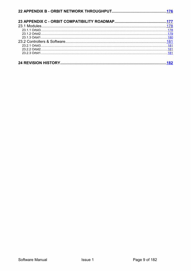
3.2 NAVIGATING THIS DOCUMENT
This is a large document, which is a useful reference when writing Orbit applications. To aid navigating the document, the following Navigation tip may be useful:It is often necessary to jump to another item and then go back to where you jumped from.This can be done in Adobe Reader by using the ‘Previous Page View’ button:
Other PDF readers will have a similar 'Previous Page View' option.
3.3 TERMS AND ABBREVIATIONS
See the 'Terms and Abbreviations' section in the Orbit3 System manual.
Software Manual Issue 1 Page 11 of 182
'Previous Page View' Button

4 SOFTWARE INTERFACING TO ORBIT
4.1 INTRODUCTION
The Orbit®3 Support Pack for Windows covers interfacing Orbit to a PC with Microsoft Windows Operating System. It contains an Install program which will installs the Orbit drivers, software libraries, applications and manuals on to your hard disc.
Included with Orbit®3 Support Pack for Windows is a COM object library, commonly known as the Orbit COM library. This is the simplest and best tool to use to communicate with an Orbit Measurement System.
See the Orbit®3 System manual for installation details.
For users that require a simple interface to an Excel spreadsheet, the Orbit Support Pack for Excel is available for purchase.See Orbit Support Pack for Excel section for more details.
4.2 ORBIT COM LIBRARY
Using the COM library greatly simplifies the development of Orbit systems since it:
• Allows for a more modern object orientated software design
• Allows the end user to avoid learning about the intricacies of the ‘low level’ Orbit interface. In particular, this:
• Seamlessly handles dynamic mode.• Calls all the necessary functions in the correct order.• Handles the timing constraints of different modules and controllers.• Handles the compatibility of modules and controllers.
• Easy to interface with other Windows based programs (e.g. Microsoft Excel)
For these reasons, the COM library is always recommended for use with new designs.
The COM can be easily interfaced to Windows based software using standard high level languages. Example programs are available that illustrate this.
4.3 ORBIT COM CODE EXAMPLES
To illustrate how to use Orbit software in different applications, various examples are provided. These are installed as part of the Orbit Support Pack for Windows.Note: The COM is recommended for use with new designs.
4.3.1 COM Examples• C++ Builder Example – this example is written using C++ Builder (RAD Studio 2009)• C# (C Sharp) Demonstrator – this example is written using Microsoft Visual C# . • Delphi Example – this example is written using Delphi (RAD Studio 2009)
Software Manual Issue 1 Page 12 of 182
• Visual BASIC Example – this example is written using Microsoft Visual Basic (Visual Studio 2008)• Visual C++ Example – this example is written using Microsoft Visual Basic (Visual Studio 2008)
4.3.2 Excel ExamplesThe Excel example workbooks all use the Orbit COM library. They can be modified to suit your application and do not need any external compilers. It is recommended that you use one of these examples to test your hardware set-up before writing any of your own code, this will give you a ‘known good’ system to return to if you experience any problems when writing your own application.
We recommend that you back up the Workbook before making any changes to the code.
If you wish to look at the VBA code for the Workbook, to see the sequence of actions required, select the Tools menu then use Macro - Visual Basic editor (or press Alt – F11).
Note. To run the VBA examples, the Macro security level in Excel should be set to Medium, i.e. “allowing you to choose whether or not to run potentially unsafe macros”.
4.3.2.1 Standard Mode Example• Orbit_Read.xls – this example demonstrates using Orbit COM in standard mode plus how to interface with an Digital Input Output Module (DIOM).
4.3.2.2 Dynamic Examples• DynamicEIMSync.xls – this example demonstrates using Orbit COM dynamic mode with the PCI Orbit network card.• DynamicNWCSync.xls – this example demonstrates using Orbit COM in dynamic mode with an Encoder Input Module (EIM) as ‘sync source’.
To use the examples simply open the Workbook and click on the “Module ID’s” tab then change the Module ID’s to suit the Modules in your application. Network 0 ID’s (channel 1) are in column B and Network 1 ID’s (channel 2) are in column D. The list of ID’s must have no gaps, so if you have 5 modules on network 0 their ID’s must be in cells B2 to B6. Now click on the “Network 0” tab and choose the Number of Modules, Collection rate, Collection size etc. that you require, then click “Start Collection” to start collecting readings. .
See the Orbit COM Library section for further details.
4.4 ORBIT DLL
The Orbit DLL (Dynamic Link Library) is the interface that handles the ‘low level’ Orbit interface. It is used by the Orbit COM for accessing all of the Orbit commands.
Modern software methods have moved away from directly using DLLs, therefore we always recommend using the Orbit COM with new designs.
Software Manual Issue 1 Page 13 of 182

The DLL can still be interfaced to Windows based software using standard high level languages, but it is not as simple as using the Orbit COM. Example programs are available that illustrate this.
Note. The Dynamic Mode and new Orbit3 commands are not available using the DLL directly.
4.4.1 DLL Examples• C Example – this example demonstrates how to interface to the DLL with C. It uses 'generic' code and should compile under any 32 bit C compiler (e.g. Microsoft Visual C++, C++ Builder). The exe is a 'stand alone' application and will run on all 32 bit platforms. • Delphi Example – this example demonstrates how to interface to the DLL with Delphi.• Visual BASIC 5 Example – this example demonstrates how to interface to the DLL with Visual BASIC 5
See the Orbit DLL - Controller Commands & Module Commands sections for further details.
4.5 USING ORBIT WITHOUT WINDOWSSome users require access to non Windows based computers (e.g. PLC – Programmable Logic Controllers). A standard RS232 interface module can be used to interface to this type of computer.The ‘Low Level’ Orbit protocol that should be adhered to is detailed in the RS232 Controller (RS232IM) section.
4.6 ORBIT TROUBLESHOOTINGIf you are having problems with interfacing with the Orbit Measurement System, it is highly recommended to use the OrbitSwReport program. This program is used to find Orbit Controllers and Modules on the Orbit Measurement System. It retrieves information about the PC set-up configuration, as well as any Orbit Software, Controllers and Modules found. This software is a useful utility for helping to diagnose software problems and resulting log file can then be sent to your supplier, along with a description of the problem itself, to aid technical support.See Orbit SW Report
5 ORBIT UTILITY PROGRAMS
These programs are all available as part of the installation of the Orbit Support Pack for Windows CD.
5.1 ORBIT COM TESTThis program is designed to demonstrate the functionality of the COM library. This program is a useful test program in its own right.
Software Manual Issue 1 Page 14 of 182
5.2 ORBIT REGISTRATION This program is used to register Orbit RS232IMs and Orbit ISA cards.Any RS232IMs or Orbit ISA networks card must be registered with this program in order to work with the Orbit software.
See Orbit3 System manual for details.
5.3 ORBIT DEMONSTRATORThis program is used to demonstrate (using bar graphs) readings from modules. The source code for this application is included as the C# (C Sharp) example.
5.4 ORBIT SW REPORTThis program is used to find Orbit Controllers and Modules on the Orbit Measurement System. It retrieves information about the PC set-up configuration, as well as any Orbit Software, Controllers and Modules found. This software is a useful utility for helping to diagnose software problems.Run the program, then click Start to collect set-up data about the versions of Orbit Software and this should find all available Orbit Networks. Then click ‘Check Modules’ to find modules on the networks found.Note that each network is separate and should be interrogated in turn by changing the ‘Orbit Network’ drop down box.Click Add Module(s) to discover modules on the selected network. Choose between entering Module Orbit identities manually, notifying or by using the Ping Modules (Orbit3 modules & controllers only) via the check boxes provided to select how to discover Orbit modules.Results for Orbit modules found are logged on screen.On exiting the program, the on screen results can be logged to a text file. Choose the appropriate file name & path and click Save.This file contains useful information about the Orbit Measurement System in question and is useful for troubleshooting & diagnosing problems.
5.5 ORBIT3 NETWORK POWER CALCULATORThis is an Excel spreadsheet used to determine power supply calculations and considerations. Refer to the Orbit System manual for Orbit installations.
5.6 ORBIT SUPPORT PACK FOR EXCEL
The Orbit Support Pack for Excel® software is intended for easy interface without the need for any programming skills. This software package enables you to take readings from up to 31 Orbit Modules forming an Orbit Network and place them in cells of an Microsoft® Excel® spreadsheet.The program is designed to work with the Orbit Controllers (Orbit NetworkCards, Orbit RS232 Interface Module and Orbit USB Interface Module).Note that this software supports Standard Measurement mode only (i.e. not suitable for dynamic, buffered or new features.
Software Manual Issue 1 Page 15 of 182
6 POWER UP CONDITIONS
On power up, the default conditions for all modules are: • Standard Measurment Mode• The Baud Rate for Standard Measurement Mode is 187.5 K Baud.• Orbit Modules default to address 0 on power up. This is to indicate that they are ‘un-
addressed’.• .
In addition, on power up default conditions for Digital Probes & AIMs are: • Resolution defaults to14 bits.• Averaging defaults to 16. (Sets the internal bandwidth)• Measurement Register Refresh Rate defaults to 244 updates per second (every 16
x 256µs = 4.096m).• The Contents of the Measurement register is the average of the last 16
measurement cycles. • The Electrical Measurement Bandwidth is nominally 100Hz.• The Baud Rate for Standard Measurement Mode can be set to 9600 Baud (Legacy
Mode). Baud rate selection takes place automatically, when the first break character command is sent. This first command should always be an OrbitRst command.
DIOM only:• Default state on all pins at switch on is INPUTs.
DIM only:• Default state is read continuous.
EIM only:• Default state is x1 quadrature mode and Reference Mark not active.
Software Manual Issue 1 Page 16 of 182

7 NEW FEATURES AND COMMANDS WITH ORBIT3New commands available with Orbit3 are:
7.1 HOTSWAP
Note: To use this mode in its simplest form requires Orbit3 compatible TCONS and Modules. However to fully use this mode requires additionally: PCI Card MK3 or Orbit3 RS232IM plus Orbit Support Pack for Windows Version 5 (or later).
Hot Swap is a feature of Orbit3 and is the ability to 'assume' a module's Orbit identity. The identity 'assumed' is stored in the module's T-Con (only written after successfully adding a module using the Add, NotifyAndAdd or Ping methods). This feature is particularly useful when replacing a module (but leaving the original T-Con in place, which contains the stored / original Orbit identity). The new (replaced) module automatically 'assumes' the original Orbit identity (from the T-Con) on power-up (if compatible**).
This means that after replacing a module, operating software does not need to change as all module identities are effectively the same as they were.
A further feature of Hot Swap mode is to store the module's last known address in the T-Con. This address is 'assumed' on power-up (if compatible**). This means that after initial set-up, operating software can be written / modified to be a more flexible and simpler design. See the FindHotswapped section for more details.
Notes
The module identity returned (e.g. via BaseModuleID in the COM or the OrbitIdentify command) is that of the actual Orbit identity, not the 'assumed' one.
In normal operation, the module Orbit identities and addresses are usually the same as they were the previous time, hence there is no need to 'assume' the Orbit identity.
** A compatible module is the same module type and stroke. For example a 2mm Digital probe is only compatible with another 2mm Digital Probe. Incompatible modules indicate this by flashing the red status LED. Note that incompatible modules do not 'assume' Orbit identities and addresses.
To clear an incompatible module, simply add this module (using the Add or NotifyAndAdd methods) to the Orbit network. This will store the module's actual Orbit identity in the T-Con and thus clear the compatibility issue.
Software Manual Issue 1 Page 17 of 182
7.1.1 Hot Swap Extra ModesThe commands detailed in the next section are extra COM methods added for Hot Swap.
7.1.1.1 FindHotswappedNote: To use this mode requires PCI Card MK3 or Orbit3 RS232IM, Orbit Support Pack for Windows Version 5 and Orbit3 compatible TCONS and Modules.Available in the COM only.This function scans the selected Orbit network for hot swap 'assumed' addresses. This allows modules to be communicated to without having to use the Add, NotifyAndAdd or Ping methods each time.Note that this feature is one command only.
Note also that the Add, NotifyAndAdd or Ping methods need to be called once, to initially store the T-Con data (hot swap 'assumed' addresses). This operation would only need to be performed once and could use standard utility programs to action this (avoiding the need to write custom software).
Note that if modules have been altered (e.g. a module has been removed), non contiguous addresses (i.e. there is a gap) will mean that addresses after the gap will be ignored. For example, if there are modules with T-Con addresses:1,2,3,5,6 then only 1,2,3 will be setup as there is a gap between 3 and 5, i.e. 5 & 6 are not set up.
7.1.1.2 ResetTConsNote: To use this mode requires Orbit Support Pack for Windows Version 5 and Orbit3 compatible TCONS and Modules.This function clears the T-Con Hot Swap data.It should only need be used when rebuilding systems from parts from existing systems, in order to clear conflicting hotswap data.(ie 2 TCONS with the same address data).
See ResetTCons section for more details.
7.2 PINGNote: To use this mode requires: PCI Card MK3 or Orbit3 RS232IM, Orbit Support Pack for Windows Version 5 and Orbit3 compatible TCONS and Modules.
This Orbit3 command interrogates the specified Orbit network to find all modules connected on it.Each module found will be set-up / added in a process that takes about 20 seconds.Orbit modules that have already been added (using Add, NotifyAndAdd or Ping methods) will not be picked up by a subsequent Ping.
Note: that due to the way the OrbitPing command works, the order (address) in which the modules are found may be different each time. Therefore, the order may need to be changed using the ReMapAddress and ApplyRemap methods.
Ping can be used in conjunction with the Save method to quickly configure a system with the modules found.
See Ping for more details.
Software Manual Issue 1 Page 18 of 182

7.3 READCURRENTINUOMNote: To use this mode requires: Orbit Support Pack for Windows Version 5 and Orbit 2 or Orbit3 Modules. This is a new function is a feature of the COM, not the moduleIt is not available as a DLL commands.
This feature allows Orbit modules to simply return their reading in the required Units Of Measure (UOM). For example, a 2mm Digital probe at mid position would return 1mm, whereas the ReadCurrent method would return 8192 counts.
For more information when using this feature with the COM, refer to the ReadCurrentInUOM section.
Software Manual Issue 1 Page 19 of 182

8 ORBIT MEASUREMENT MODES
See the Orbit3 System Manual for a description of the Measurement Modes. Their are three measurement modes, standard, buffered and dynamic.
8.1 STANDARD MEASUREMENT MODE
In this mode the Orbit Modules are communicated with on an individual basis. Each module is asked for its measurement data by the controller as required.
Standard mode requires that all modules that are to be communicated too are set to an address using their unique Orbit Identity. Once assigned, that module will communicate with that address. The general method depends on whether the COM library or the DLL is used.
8.1.1 COM Library Method• Connect to Orbit.• Add Module with Orbit Identity to Selected Network (Module0)• Call Read method (Reading = Module0.ReadCurrentInUOM() ). See Reading an
Orbit Module.
8.1.2 DLL Method• Connect to Orbit.• Reset Selected Network• Wait 0.5 seconds• Send OrbitSetaddr with Orbit Identity to Selected Network (at address 1)• Call OrbitIdentify (at address 1)• Call OrbitGetinfo (at address 1)• Work out Units Of Measure (UOM) and Counts Per Unit Of Measure (CPUOM).• Call OrbitRead1 or OrbitRead2 command (depending on module being
communicated with). See Reading an Orbit Module.• Calculate Reading (using OrbitRead result and CPUOM).
8.1.3 COM Library Versus DLLAs can be seen from the general method described above, it can be clearly seen how much simpler it is to use the COM library than to use the DLL. See Orbit COM Library for more details.
8.1.4 Difference Mode
In Standard measurement mode it is possible to set the Modules into Difference mode. In Difference mode, readings are taken continually and the maximum, minimum, number and sum of readings are stored in the module itself. These values can be read at any time using the appropriate Orbit commands. This mode has the advantage that the modules themselves do the calculations, not by the controlling software. Thus, the Orbit Communication speed does not affect reading rate.
Software Manual Issue 1 Page 20 of 182
Notes:The sum and number of readings can be used to simply obtain the mean (average) reading.For Digital Probe and AIMs, Difference mode is only available in 14-bit resolution. For Linear Encoder, Difference mode does not return the sum and number of readings.
For Digital Probe and AIMs, the Measurement Register Refresh Rate during Orbit Difference Command is 244 updates per second (4.096ms).
When the Module exits from Difference Mode, the measurement conditions prior to entering difference mode are restored.
8.1.5 Programmable Resolution
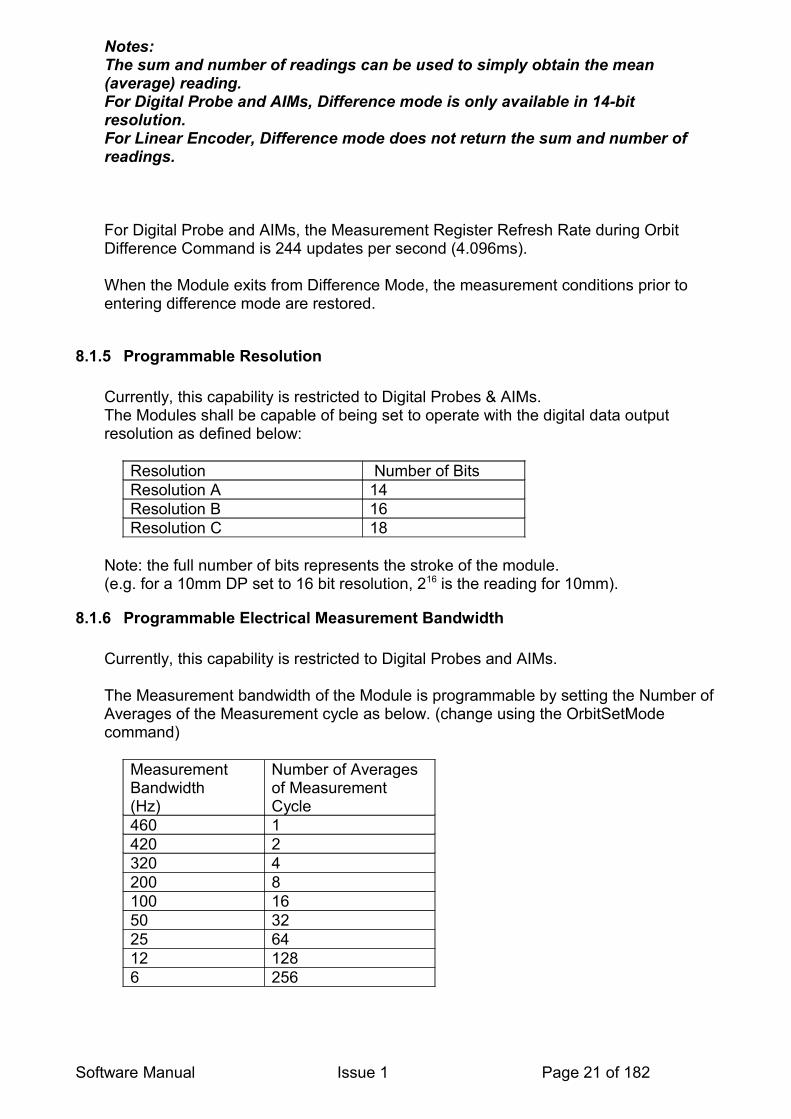
Currently, this capability is restricted to Digital Probes & AIMs. The Modules shall be capable of being set to operate with the digital data output resolution as defined below:
Resolution Number of BitsResolution A 14 Resolution B 16 Resolution C 18
Note: the full number of bits represents the stroke of the module.(e.g. for a 10mm DP set to 16 bit resolution, 216 is the reading for 10mm).
8.1.6 Programmable Electrical Measurement Bandwidth
Currently, this capability is restricted to Digital Probes and AIMs.
The Measurement bandwidth of the Module is programmable by setting the Number of Averages of the Measurement cycle as below. (change using the OrbitSetMode command)
Measurement Bandwidth(Hz)
Number of Averages of Measurement Cycle
460 1420 2320 4200 8100 1650 3225 6412 1286 256
Software Manual Issue 1 Page 21 of 182

8.1.7 Programmable Baud Rate
The Baud Rate for standard measurement mode is programmable to 1.5MB/s (High Speed) or 187.5kB/s (Low Speed). The Baud rate is programmed using the OrbitSetMode command.
A check is performed on power up, whether to switch to 9600 Bits/s (Very Low Speed or to default to 187.5kB/s (Low Speed) - see section on Power Up Conditions.
Software Manual Issue 1 Page 22 of 182
8.2 BUFFERED MODE
8.2.1 Introduction to Buffered Mode
Buffered Orbit modules have internal memory that can store readings which can then be retrieved; they also have the ability to take synchronized readings at a user programmable rate. It offers the ability to synchronize readings with other modules on the same Orbit network. Since readings are stored locally and downloaded when finished, the Orbit network is not communicated on whilst buffering is in progress. Thus readings are not limited by the Orbit bus speed, giving rise to increased reading rates
Currently buffered capability is restricted to Digital Probes (including Mini probes and Lever Probes), AIMs and DIOM.
8.2.2 Synchronized Mode (Buffered)
Modules are synchronized to each other by sending a Control command. After this, the crystal oscillator on each module maintains synchronisation. It is advisable to synchronize and then take the readings within a short period of time to eliminate any possible errors due to the module’s electronics oscillator drifting.
In buffered mode, up to 3000 readings can be stored at a maximum rate of 244 reading / second. When completed, stored readings are downloaded in order for processing.
Measurements are taken at a rate determined by a pre-programmed delay and stored within an internal buffer. All measurements are 14 bit. (higher resolutions (16 or 18 bits) are not allowed).
synchronized buffered operation is initiated via the OrbitControl command which synchronizes all modules set into synchronized mode. There is a 12ms delay before the first measurement is written into the internal buffer.
The Delay between readings is user configurable – see section on the OrbitSetMode command for more details.
Readings are obtained from the module via the ReadBuffer1 command. This reads up to 32 buffered readings at a time. The next ReadBuffer1 command sent returns the next 32 readings and so on – until there are no more readings left in the buffer.
8.2.3 Sample Mode Buffered
This mode allows modules to sample, synchronously on receiving a sample command.
A reading is taken each time the module receives the OrbitControl command (action=Sample). Each new reading is placed in a buffer in the module and the buffer pointer is incremented. The Digital Probe buffer can store up to 3000 readings.
Readings are obtained from the Digital Probe via the OrbitReadbuffer1 command.
Software Manual Issue 1 Page 23 of 182

A new reading being transferred to the buffer as soon as the OrbitControl command (action=Sample) has been received (delay = approximately 250µs at 187.5kBaud).
8.2.4 Sample Mode Buffered - Using EIM
An alternative Sample Buffered Mode is available for use with an Encoder Input Module (EIM). The Encoder can be set to generate the sample control command itself, instead of the Orbit Controller. For example, samples can be taken every time the Encoder moves one degree.
To action this mode, the following steps should be performed:Set the Buffered Modules to Sample Mode Buffered Mode (via OrbitSetmode command)Set the EIM to sample mode buffered (via OrbitSetmode command)Set the Network Controller to Idle
Software Manual Issue 1 Page 24 of 182
8.3 DYNAMIC MODE
8.3.1 Introduction to Dynamic ModeDynamic mode provides a method of obtaining synchronized measurements at high speed from Digital Probes, EIM, AIM, DIOM and other compatible Orbit products. This mode is of importance when measuring moving objects. It gives the user the ability to take high-speed measurements from a set of transducers that are sampled at the same point in time – i.e. simultaneous sampling. Dynamic mode uses high speed Orbit communication (1.5 MBaud) and is only available with a PCI Mark 2 and above network card.Operation of dynamic mode (listed in this document) is pretty straightforward to use / program. Writing an Orbit Dynamic application is a fairly simple task, which is made easy by the use of the Orbit COM library. This hides all the low-level complexity of the Dynamic system and allows you to concentrate on the application itself.
To help you write your application we recommend that you refer to the Orbit COM Library & COM Programming Techniques and Guidelines sections of this manual before starting.
Various examples for using the COM with Dynamic Mode can also be found on the Orbit Support Pack for Windows installation CD.
8.3.2 Why Use Dynamic ModeIn standard measuring mode (non-dynamic), readings are read back from Orbit modules as required. A command to request a reading is transmitted from the controller & the reply from the Orbit module is then received. A finite amount of time is taken with the Orbit communications to transmit and receive data.A single module on a network works well in this mode, as there is only the one module to communicate to, which gives fast reading rates. However, when there is more than one module on the network, there are several issues to consider:
• Is it important to synchronize readings?• What reading rate is required?• What type of Orbit controller is to / can be used? (e.g. PC card, RS232IM etc.)
If the required reading rate is not high & no synchronization is required, standard measuring mode (non-dynamic) should be still be used.
Dynamic mode allows the highest possible reading rates to be achieved and for all readings to be synchronized together. Synchronization is important to allow two (or more) modules to be read at the same time. The Dynamic measurement system captures readings from each Orbit module on the network and returns them to the Orbit controller within a specific time period of 256μs. This allows multiple modules to be read, synchronously, as fast as 3906 readings a second.
8.3.3 Alternatives to Dynamic ModeMost modules have the Buffered Mode available. Buffered mode allows a network of modules to store a collection of up to 3000 readings, synchronously. The completed collection of readings can then be
Software Manual Issue 1 Page 25 of 182
downloaded to the controller. Note that this mode is not available on modules without the buffered mode enabled. Note also, that buffered mode is slower than dynamic and not as flexible. Therefore, it is not recommended for new designs, where dynamic mode is available for use.
Buffering Limitations: Probe reading rate = 250/secRotation speed must be limited if small features are to be detected.Limited to 14bit Resolution.Over a period of time, synchronization of the probes will drift by up to a maximum of +/-256µS.
However, Buffered Mode is supported with • PCI /PC104 Network cards.• Older PC cards (ISA, Mark 1 PCI cards).• USB Interface Module.• RS232 Interface Module.• RS485 Interface Module
Therefore it is a good option to use when Dynamic Mode is not available (i.e. when you cannot use a PCI network card)
See Buffered Mode section
8.3.4 Resolution in Dynamic ModeReadings from modules in Dynamic Mode can still be set to 14, 16 or 18 bit resolution. The resolution should be set to the desired setting before starting dynamic collections
8.3.5 Collection RateDynamic Mode operates using 256μs period time slots. In each 256μs period, readings from up to 8 Orbit modules can be collected.To accommodate larger numbers of Orbit modules, the periods are chained’ together in groups of 2 or 4. This grouping is referred to as the Collection Rate (1k, 2k or 4k) – the timing for the three Rates is shown in table 1. Every 256μs period starts with a ‘Sync’ pulse that is generated by the Network card or externally from an Encoder Input module.Note. The EIM has a minimum time slot of 290µS.
Table 10. Collection rate detailsCollection Rate
Maximum Modules per Orbit Network (Channel)
Number of Time periods per cycle
Reading Rate for each Module (Rdgs/Sec)
Time between capture phase (µS)
4k 8 1 3906 2562k 16 2 1953 5121k 31 4 977 1024
To ensure that the ‘skew’ between each of the modules’ readings is kept to a minimum all modules will capture their current reading at the beginning of the dynamic cycle. The time between each capture phase is determined by the Collection Rate as shown in the table above.
Software Manual Issue 1 Page 26 of 182

Note: Both channels on an Orbit PCI Network Card may be used in Dynamic Mode, eg. for 16 Orbit modules at 4k collection rate; use the two Orbit channels, both set to 4k rate with 8 modules.
Dynamic TimingEach of the three Collection Rates follows a specific sequence of time periods as shown in the table below.
Table 11. Time period sequences (for each Network Channel)(1) Collection of 8 readings using 4k
RateA A A A A A A A
(2) Collection of 4 readings using 2k Rate
A B A B A B A B
(3) Collection of 2 readings using 1k Rate
A B C D A B C D
Where each letter indicates a 256µS time period allocated to a range of Module addresses, as below:
Table 12. Module Addresses Allocated to each Time PeriodTime Period A B C DAllocated to Modules with Addresses: 1 to 8 9 to 16 17 to 24 25 to 31
Important Note: Regardless of which Rate is being used all the modules will capture their readings at the beginning of time period ‘A’.
The maximum modules figure shown in the first tableis for one Network channel only, by using the second Network the number of modules for any given Collection Rate can be doubled. The second Network has exactly the same timing as the first, thus maintaining module to module synchronization across both Networks.
8.3.6 Dynamic Mode System Constraints
To prevent loss of information the Measurement Bandwidth and the Measurement Register Output Rate should be programmed compliant with the table below:
Measurement Bandwidth(Hz)
Measurement Register Output Rate(Readings per second)
450 4K Mode420 4K or 2K Mode320
4K, 2K or 1K Mode
2001005025126
The programming of the correct Bandwidth and Register Output Rate is the responsibility of the user. The DP will not provide error checking.
Software Manual Issue 1 Page 27 of 182

In conjunction with the Network Card, Orbit Modules and Probes operating in Dynamic Mode can be configured as per the table below
Mode Number of Probes/Dynamic Modules
Measurement Update TimeµS
Maximum Measurement BandwidthHz
4K 8 256 4602K 16 512 4201K 30 1024 320
8.3.7 Dynamic Collection in Multicard Mode
To run Dynamic Collection on a larger number of Modules, Dynamic Multicard operation should be used.This requires multiple Orbit Network PCI cards interlinked - see the Orbit System Manual for Hardware details.This feature enables the user to connect higher numbers of Modules and still perform a collection at 3906 readings/Sec (4k rate), while retaining synchronous readings across all networks.Also, it is possible to achieve the higher 4k rate on 32 Modules (instead of the standard 16).Up to 4 PCI cards may be linked giving the user a maximum of:64 Modules @ 4k rate or 128 Modules @ 2k rate or 256 Modules @ 1k rate.
Note. It is necessary to have Mark 2 Orbit PCI Network Cards with firmware version V2.60 or greater for this function. The utility, OrbitSwReport may be used to check the firmware version.
8.3.7.1 Software Operation for Multicard UseNo additional software commands are needed to perform Multicard Collections.The PCI Network Cards automatically detect whether the cards are linked as 'Master' or 'Target'.Simply use the standard COM Dynamic methods.
8.3.8 Hardware Requirements for Dynamic ModeThe Dynamic measurement system requires an Orbit Network PCI card (Mark 2 or later) to be installed.To use the Dynamic mode, the Orbit COM library must be used. The Orbit COM is installed as part of the Orbit Support pack for Windows.
Note: Dynamic mode is not available with:• Older PC cards (ISA, Mark 1 PCI cards).• USB Interface Module.• RS232 Interface Module.• RS485 Interface Module.
Software Manual Issue 1 Page 28 of 182

8.3.9 Software Requirements for Dynamic Mode
To be able to use Dynamic mode, ensure that you are running the latest software for modules, controllers and Orbit Support Pack For Windows.
Notes: • ORBIT SOFTWARE REPORT PROGRAM (510346) should be run to check the firmware / software of the Orbit Measurement system connected.This software is supplied on the Orbit Support Pack for Windows CD.• Contact your supplier for upgrades
8.3.10 Hints and Tips on Using Dynamic Mode• Make sure your software & firmware is up-to-date for running dynamic mode.
• Refer to the Orbit COM Library section of this manual whilst writing any code.
• See the supplied Dynamic Examples.
• If using an EIM as a ‘sync source’, remember to set the Orbit network to High Speed before setting the .TxSync and ReAction properties .
• EIM does not send Sync pulses - the EIM could be counting in the wrong direction, confirm that when the encoder is rotated the direction of count is as expected (see below).
Note: TxSync is positive (e.g. .TxSync = 5) the EIM will be expecting the count to increase
when the Encoder is rotated. TxSync is negative (e.g. .TxSync = -5) the EIM will be expecting the count to
decrease when the Encoder is rotated.Digimatic Interface Module Code Examples
Software Manual Issue 1 Page 29 of 182

8.3.11 Dynamic Schemes
8.3.11.1 Dynamic Scheme 1 - Network Card as the Sync sourceThis method uses the Orbit Network card to provide a stream of Sync pulses 256μs apart, the collection rate and the number of readings determine the total number of pulses needed.If required, the second Network (Channel 2) can be used to increase the amount of modules in the collection, all that is required is that the PrepareForCollection method is applied to the second network.
Figure 1 Typical application using an Orbit PCI Network card as the Sync source
After the modules on each Orbit Network have been prepared via the PrepareForCollection method of OrbitServer, the StartCollection method is used to start the collection. The CollectionRate and NumCollectedReadings parameters determine the number of Sync pulses that will be transmitted.
If a continuous collection has been started (NumCollectedReadings = 0) the StopCollection method is used to stop the collection (finite Collections NumCollectedReadings <> 0 automatically stop on completion). The StopCollection method can also be used to stop a Finite Collection if required.
Software Manual Issue 1 Page 30 of 182

8.3.11.2 Dynamic Scheme 2 - Encoder as the Sync sourceThis method uses an Encoder Input module (EIM) on channel 1 to provide the Sync pulses required for a Dynamic collection, the collection rate and the number of readings determine the total number of pulses needed. As with scheme 1, the second Network (Channel 2) can be used to increase the amount of modules in the collection.
Figure 2 Typical application using an Encoder Input Module (EIM) as the Sync source
Important Note: When the EIM is used for a ‘Sync source’, it does not form part of the collection. In other words, it is not possible to collect readings from the EIM if it is being used as a ‘Sync source’. The EIM used as a ‘Sync source’ must be added after the Modules used for the collection, i.e. it should be the last Module on the network.
It is important to note that Sync pulses are generated when the current EIM count matches the value in the EIM comparison register. This comparison is an absolute, which means it is possible to set the EIM into a condition where a match is never met, as in Example 1 below.
Example 1. Match condition is never met
Encoder continuously running. EIM counter is Preset to 0 (this will also load 0 into internal comparison register) some time later .TxSync is used to start the collection but because the count is now greater than 0 the initial match is never made.It is recommended that in most applications RefAction is set to either 5 (Reset counter / enable Sync) or 6 (Preset counter / enable Sync), this will stop this situation occurring.
Software Manual Issue 1 Page 31 of 182

8.3.12 Examples of Using Dynamic ModeThe following are general examples to illustrate what Dynamic Mode offers.
8.3.12.1 Dynamic Mode Example Using Time Triggered Readings, This option is used to measuring the profile of a rotating cam shaft.In this example, a cam shaft has six DPs (Digital Probes) measuring various positions. A motor rotates the cam shaft and a rotary encoder, connected to a EIM (Encoder Input Module), measures the angle of rotation.
The six DPs should be synchronized together – i.e. they should all take their readings at the same time with no skew. The EIM will measure the angle at which the six DPs are being read. The readings are all synchronized directly from the PCI card itself.
Dynamic mode can be used in this particular case to read every 256μs (approximately 4k readings / second). Enough readings should be taken to ensure that a complete cycle has taken place.
8.3.12.2 Dynamic Mode Example Using Angle Triggered ReadingsThis option is used to measuring the profile of a rotating cam shaftIn this example, the same set-up is used as the example above, i.e. 1 cam shaft with six DPs and an EIM.
It is possible to set Dynamic Mode to synchronize readings directly to the EIM’s position. Thus readings from the DPs are taken when the EIM reads a pre-defined value (e.g. every degree of rotation).
The six DPs will be synchronized together – i.e. they should all take their readings at the same time. However, the EIM now takes a more active role and directly synchronizes when the readings take place.
Thus, the readings taken are more useful to the application, since they are directly relative to the angle of rotation.
Various settings are provided to allow flexible methods to start Dynamic mode using the EIM. These include using the EIM’s reference mark. Note. The EIM must be the last module added on the Channel.See later sections for more details.
8.3.13 Dynamic with EIM used as a Sync Source
8.3.13.1 Calculating the number of Sync pulses required when using EIM as sync source
As shown in Table10 the number of Time periods (Sync pulses) required per collection cycle depends on the Collection Rate used. When the EIM is being used as the Sync source it is important to understand that each Sync pulse only transfers data from a maximum of 8 modules per Network. If the Collection Rate is set to 1k or 2k then additional Sync pulses are required to transfer all the data.This can best be explained by means of a simplified example below.For full details see Steps in Performing a Dynamic Collection with an EIM
Software Manual Issue 1 Page 32 of 182
We require that the Modules on the network are to be read every degree,Using an Encoder with 7200 pulses per revolution .
Scenario 1
• Use .TxSync = 20 to set EIM to generate a Sync pulse ever 20 Encoder pulses (360 per revolution – one per degree). Explanation: as the 4k rate is being used, readings from all of the 8 modules are sent in time frame A. All 8 modules are synchronized to each other, so only one EIM sync pulse should be generated per degree.
• PrepareForCollection to set each Network. • Use StartCollection (4, Number of Readings) to start the collection.
Explanation: as there are 8 modules, the maximum (4k) rate can be used.
The time period sequence for this set-up is shown in Table11 (1)
Scenario 2
• Use .TxSync = 10 to set EIM to generate a Sync pulse ever 10 Encoder pulses (720 per revolution – two per degree).
Explanation: as the 2k rate is being used, readings from the first 8 modules are sent in time frame A and the last 2 modules are sent in time frame B. All 10 modules are synchronized to each other, but two EIM sync pulses should be generated per degree.• Use PrepareForCollection to set each Network. • Use StartCollection (2, Number of Readings) to start the collection.
Explanation: as there are more than 8 modules, the slower (2k) rate should be used.
The time period sequence for this set-up is shown in Table11 (2)
In both cases the readings from all the modules in the collection are captured every degree.
Note: In this example, if a 1k Collection Rate were required (more than 16 modules per Network) set .TxSync = 5 to allow all modules to be read every degree.
8.3.13.2 Sync Pulse Rate when using EIM as a Sync sourceWhen using an EIM to generate Sync pulses the rate is determined by several factors:
• Encoder rotation speed• Number of encoder pulses per revolution • Number of encoder pulses required per Sync pulse
The Orbit EIM Dynamic system is based around a minimum time between sync pulses of 290µs. Because it is possible to violate this timing the calculation below should be made to guarantee reliability.
Software Manual Issue 1 Page 33 of 182
8.3.13.3 Speed Calculations when using an EIM as a Sync sourceMaximum speed (Revolutions per second) = (N / P) * 3906
Where P = Encoder pulses per revolution and N = Number of encoder pulses required per Sync pulse
Example with P = 1000 (Encoder with 1000 pulses / rev) and N = 2
Max speed = (2 / 1000) * 3906 = 7.8 revs / s If this maximum speed is exceeded, the Network card will automatically stop the collection (.CollectionMode = cmDone) and place an error value (0x8000FA) in the collected readings at the place where the timing violation occurred. The termination of the collection will also release the EIM from TxSync Mode.
The EIM will have also detected the timing violation and set its error status, if the EIM is read via the OrbitModule ReadCurrent method it will return an ‘Encoder Module Sync Gap Error’, this can be cleared by using the OrbitModule GetStatus method.
Software Manual Issue 1 Page 34 of 182

9 ORBIT COM LIBRARY
9.1 INTRODUCTIONThe Orbit COM library provides a Component Object Model (COM) Object that enables users of the Orbit Measurement System to communicate with any PC Based Orbit Controller and the complete range of Orbit Modules. Orbit COM provides a language independent library capable of easy integration into any user application. Most of the commonly available programming languages are supported as well as an automation capability for use with several MS Applications (Word, Excel etc.).Note. To make use of the Dynamic measurement modes of the Orbit Measurement System, it is necessary to use the COM Software.
Using the Orbit COM library simplifies Orbit Measurement System implementation by automatically performing some of the lower level tasks, these include:
• Easier Module Management with Add and Remove Methods.• Single Call NotifyAndAdd method.• Find Hotswapped Command• Use of single Read (and ReadDiff) commands that perform the correct Read1 or
Read2 call dependent on what probe is in use.• Any module specific delays, such as the delay required after an OrbitRst command,
are performed automatically within the COM library.• Simple control for entering High speed mode.• An easy interface for making High speed simultaneous readings (Orbit Dynamic).
The key characteristics of COM are
• COM stands for Component Object Model(follows on from DDE and OLE).
• COM is a vital building block of Windows andMicrosoft Applications.
• A COM library gives a language independent library, capable of easier integration into any user application,written in any of the commonly used available Languages.
• It is self contained and contains all the informationnecessary to allow easy import into the users developmentenvironment (VB, VBA, VC++, Delphi etc).
A secondary aim of the COM library design is to simplify the use of the Orbit System, by performing some work for the user, such as:
9.2 TARGET LANGUAGES
The COM library is able to be used from Visual C++, Visual Basic, Delphi, C#, LabView and any other Language supporting import of COM Type Libraries.
Software Manual Issue 1 Page 35 of 182

9.3 EXAMPLESExamples can be found on the Orbit Support Pack for Windows CD. They are also installed as part of the Orbit installation process and will be located in the 'COM examples' sub-directory of Orbit Support Pack for Windows.
9.4 COM LIBRARY OVERVIEWThe following diagram shows a top-down view of the Orbit COM Object library. The Primary COM object is OrbitServer; beneath this are other objects that are created automatically when OrbitServer is created. Each object has a set of functions or ‘Methods’ that are used to initiate specific actions and a set of parameters or ‘Properties’ that can be read or set.
See below for an explanation of each object and for further details, see the following sections:
OrbitServer ObjectsOrbitNetworks ObjectsOrbitModules Objects
Software Manual Issue 1 Page 36 of 182

9.4.1 Primary COM ObjectObject name: OrbitServerOrbit Server is the primary COM Object in the Orbit COM hierarchy.It contains the whole system, connecting to it, disconnecting from it and providing system wide controls, providing the network's object to the users and maintaining it.
9.4.2 Networks Manager ObjectObject name: OrbitNetworksThe Networks object maintains and manages all available networks on the PC, providing information about how many networks are available and providing a simple interface to them and providing and maintaining the individual Network objects.
9.4.3 Network ObjectObject name: OrbitNetwork.
The Network Objects are a software model of the network channel hardware, providing information about the network and controls (such as speed settings, and dynamics readings controls), also providing and Maintaining the Modules Object.Each Network Object represents a single Orbit network channel.
9.4.4 Modules Manager ObjectObject name: OrbitModules.Managing object for all the OrbitModule objects currently active on a specific OrbitNetwork.The Modules Objects maintains the individual module objects providing interfaces for adding and removing modules and for directly interfacing with the individual module objects (for reading and setting of their properties etc).It manages all the OrbitModule objects currently active on a specific OrbitNetwork.
9.4.5 Module ObjectObject name: OrbitModule.Represents a single Orbit module.The Module Objects provides a model of each individual connected orbit module exposing functions and properties that enable to user to read the modules and set their properties.Each Module Object represents a single Orbit module.
Software Manual Issue 1 Page 37 of 182
9.5 IMPORTING THE ORBIT COM LIBRARY
It is a requirement that the Orbit COM library has been installed before starting the import procedure. The installation is accomplished by installing the Orbit Support Pack for Windows, Version 5.0 or above.
The library can then be imported into any project that requires Orbit COM functions.
This Chapter describes the process of configuring the Orbit COM library for each of the programming languages listed below:
• Microsoft VBA (Visual Basic for Applications) • Microsoft VB (Visual Basic) Version 6• Microsoft Visual C/C++ Version 6• Delphi Version 5• C++ Builder Version 5
For other development platforms and or versions supporting the COM interface, please consult the relevant documentation supplied with the specific language.
Software Manual Issue 1 Page 38 of 182

9.5.1 Microsoft VBA (Visual Basic for Applications)
To import the Orbit COM library, enter the Visual Basic editor and select the Tools/References menu option.
Software Manual Issue 1 Page 39 of 182
Visual Basic Project Window.
Menu option for importing COM Type libraries.

Then, from the displayed dialog search through the list of available references for the Orbit COM library and select it with the mouse.
Please consult the VBA Help files for more information on this dialog.
Finally, click on the OK button.
The Orbit COM library will now be available for VBA applications. Please see the example program code Chapter under Creating an Orbit COM Server Session for more information.
Software Manual Issue 1 Page 40 of 182
List of available COM Type libraries.

9.5.2 Microsoft Visual Basic
To import the Orbit COM library, start Visual Basic and select the Project/References menu option.
Software Manual Issue 1 Page 41 of 182
Visual Basic Project Window.
Menu option for importing COM Type libraries.
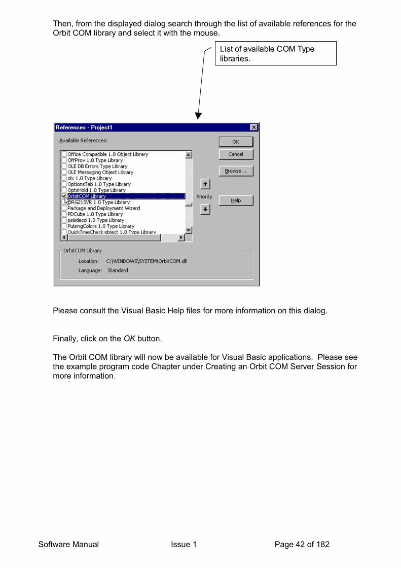
Then, from the displayed dialog search through the list of available references for the Orbit COM library and select it with the mouse.
Please consult the Visual Basic Help files for more information on this dialog.
Finally, click on the OK button.
The Orbit COM library will now be available for Visual Basic applications. Please see the example program code Chapter under Creating an Orbit COM Server Session for more information.
Software Manual Issue 1 Page 42 of 182
List of available COM Type libraries.
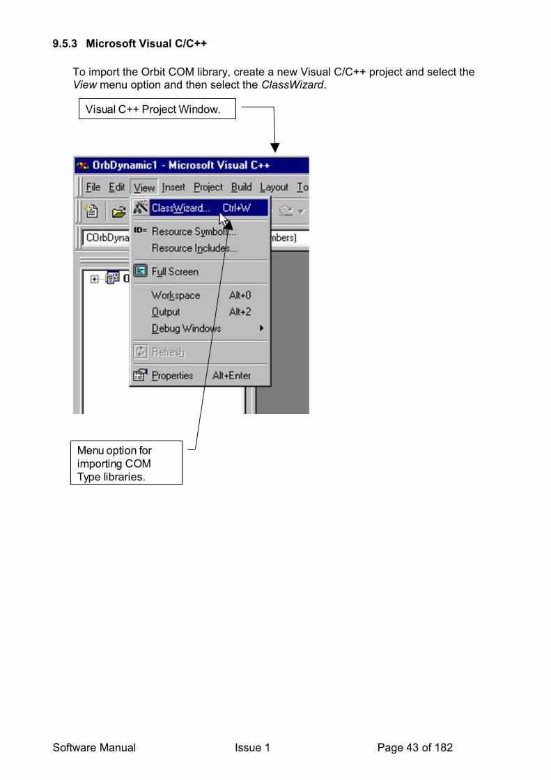
9.5.3 Microsoft Visual C/C++
To import the Orbit COM library, create a new Visual C/C++ project and select the View menu option and then select the ClassWizard.
Software Manual Issue 1 Page 43 of 182
Visual C++ Project Window.
Menu option for importing COM Type libraries.

The following dialog will be displayed. Click on the Add Class… button and then select the From a type library… menu option as shown.
Please consult the VC++ Help files for more information on this dialog.
This will produce a file requester dialog which is used to select the OrbitCOM.dll file that was copied onto the computer during the installation of the OSPW Version 5.0 (or above) software. The location of this file depends on the version of the Windows Operating system installed; it is normally the System32 sub-directory.
E.g. For a standard Windows XP installation on drive C, the complete path would be:C:\Windows\System32\OrbitCOM.dll
Software Manual Issue 1 Page 44 of 182
MFC Class Wizard dialog used for importing COM Type libraries.
Add Class… button used for Type library selection.

The following diagram shows the selection of the Orbit COM library file from a Windows98 system:
Software Manual Issue 1 Page 45 of 182
Standard Windows File selection dialog.
Click Open to start importing.
Selection of the OrbitCOM type library.

Having located the file, click on the Open button, which will then display the following Confirm Classes dialog:
Please consult the VC++ Help files for more information on this dialog.
Click the OK button to confirm and then finally click on the OK button on the MFC ClassWizard dialog to complete the process. The Orbit COM library is now available to the project and a machine generated IDispatch wrapper class will have been created automatically. This wrapper class is located within the header file orbitcom.h that can be included in the necessary project source files to provide access to the methods and properties of the Orbit COM object. Please see the example program code Chapter under Creating an Orbit COM Server Session for more information.
Software Manual Issue 1 Page 46 of 182
List of classes associated with the selected Type Library.
Click OK to confirm the import.

9.5.4 Delphi
To import the Orbit COM library start Delphi and select the Project/Import Type Library menu option.
Software Manual Issue 1 Page 47 of 182
Delphi Project Window
Menu option for importing COM Type libraries.

Then, from the displayed dialog search through the list of available references for the Orbit COM library and select it, as shown below.
Please consult the Delphi help files for more information on this dialog.
Please ensure that the Generate Component Wrapper option is not selected. For the example program code described in this manual we will not be creating a Delphi specific component. To complete the operation click on the Create Unit button which will then generate an OrbitCOM_TLB.pas unit, which can then be used within your projects. Please see the example program code Chapter under Creating an Orbit COM Server Session for more information.
Software Manual Issue 1 Page 48 of 182
List of available COM object Type libraries.
Options to add and remove COM Object Type libraries.
Option for creating Delphi specific components. N.B. please see note below.
Button for creating the required Delphi unit.
List of classes associated with the selected Type Library.
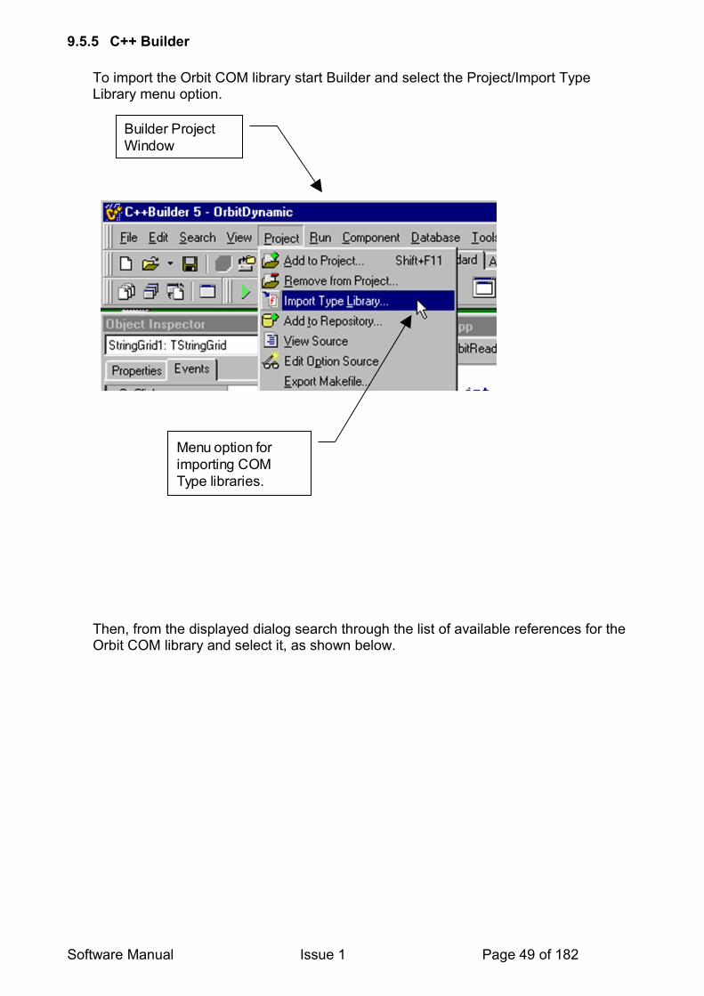
9.5.5 C++ Builder
To import the Orbit COM library start Builder and select the Project/Import Type Library menu option.
Then, from the displayed dialog search through the list of available references for the Orbit COM library and select it, as shown below.
Software Manual Issue 1 Page 49 of 182
Builder Project Window
Menu option for importing COM Type libraries.

Please consult the Builder help files for more information on this dialog.
Please ensure that the Generate Component Wrapper option is not selected. For the example code described in this manual we will not be creating a Builder specific component.
To complete the operation click on the Create Unit button which will then generate an OrbitCOM_TLB.cpp file and an OrbitCOM_TLB.h file, both of which can then be used within your projects. Please see the example program code Chapter under Creating an Orbit COM Server Session for more information.
Software Manual Issue 1 Page 50 of 182
List of available COM object Type Libraries.
Options to add and remove COM Object Type Libraries.
List of classes associated with the selected Type Library.
Option for creating Builder specific components.N.B. please see note below.
Button for creating the required Builder unit.

9.5.6 C Builder - RAD Studio 2009
To import the Orbit COM library start Builder and select the “Component.Import Component” menu option.
Then select Import Type Library and click next
Select the Orbit COM library from the list then click next
Software Manual Issue 1 Page 51 of 182
Menu option for importing COM Type libraries.
RAD Studio C++ Builder Project Window

Software Manual Issue 1 Page 52 of 182
Select OrbitCOM Library
Click Next

Enter a location for the unit, then click Next.
Software Manual Issue 1 Page 53 of 182
Enter a unit directory.
Click Next

Select Create Unit then click Finish, The unit that is created will need to be added to the projects where the Orbit COM is required.
Software Manual Issue 1 Page 54 of 182
Create Unit
Click Finish

9.5.7 Microsoft Visual C# (2008 Express Edition)
To be able to use the COM a reference needs to be added to the project. This is done by selecting “Project.Add Reference”
Then Select the “COM” tab and click on “Orbit COM library” from the “Component Name” list, then click “OK”
Software Manual Issue 1 Page 55 of 182
MS Visual C# Project Window
Add Reference to OrbitCOM Object
Select COM tab
Select OrbitCOM Library
Click OK

9.6 USING THE ORBIT COM LIBRARY
When attempting to use the COM, refer to the examples supplied as part of the Orbit Support Pack for Windows.Also, a useful tip is that most modern programming environments have a Code Completion function. This feature can be used to explore the different properties and methods of the COM.Some examples of Code Completion are shown here.
9.6.1 Microsoft VBA (Visual Basic for Applications)The Code Completion feature shows the object's available properties and methods / functions.The screenshot next shows Orbit's (OrbitServer object) available properties and methods / functions. This shows that “Connect” is a method. The Code Complete feature can be turned on using the <Ctrl> <SPACE> key combination.
9.6.2 C Builder - RAD Studio 2009The Code Completion feature shows the object's available properties and methods / functions as well as the required parameter and return data types.The screenshot next shows OrbServ's (OrbitServer object) available properties and methods / functions. This shows that “Connected” is a property of type boolean. The Code Complete feature can be turned on or off from Tools->Options or use the <Ctrl> <SPACE> key combination.
Software Manual Issue 1 Page 56 of 182
10 ORBITSERVER OBJECTSThis is the primary Orbit COM object that must be created by the user before any of Orbit’s methods and properties can be accessed. Its methods may be put into two categories:
• Connection and disconnection from Orbit networks.• Starting and stopping a dynamic data collection across Orbit networks.
A finite collection is one where the NumCollectedReadings parameter is 1 or more.A continuous collection is one where the NumCollectedReadings parameter is 0.The StopCollection method is used to stop a continuous collection.
10.1 METHODS
10.1.1 AbortCollectionParameters: None.Returns: Nothing.Used to stop collection and reset all networks.This method can be used to correct network ‘lockups’ caused by incomplete collections. Requires a Disconnect after use.
10.1.2 ConnectParameters: None.Returns: Nothing.Connects to all available Orbit networks and resets each one ready for use. This initialises the Orbit Measurement System to find all registered Orbit Controllers and their networks.
VB Example:
‘Creates an OrbitServer object.Dim Orbit As New OrbitServer
‘Connects and initialises all Orbit networks.Orbit.Connect
Print "Found " + Str$( Orbit.NumNetworks ) + " Orbit networks."
10.1.3 DisconnectParameters: None.Returns: Nothing.Disconnects from all connected Orbit networks and frees resources that were created using Connect. This should be called at the end of the user's application to 'shut down' the COM.
10.1.4 StartCollectionParameters: ( Int CollectionRate, Int NumCollectedReadings)Returns: Nothing.
Starts a dynamic data collection on all networks that have been prepared for collection, at the given collection rate and number of readings.
Software Manual Issue 1 Page 57 of 182
10.1.5 StopCollectionParameters: NoneReturns: Int, 0 = successfulUsed to stop a continuous collection, or intentionally abort a finite collection before it has completed. (Finite collections are automatically stopped on completion.)
10.2 PROPERTIES
10.2.1 CollectionDoneSet True once a Dynamic collection has completed.
10.2.2 COMVersionReturns the version of the Orbit COM library as a string.
10.2.3 ConnectedReturns the status of the current Orbit networks connection as a Boolean, i.e. True = connected, False = disconnected.
10.2.4 IFVersionNumberReturns the version of the Orbit_IF.dll (Orbit Interface) file installed on the user’s computer, as an integer.
10.2.5 IFVersionStrAs per IFVersionNumber but returns a string.
10.2.6 NetworksProvides access all available Orbit networks found using the connect method described above.
10.2.7 NumNetworksReturns the number of Orbit networks found as an integer.
10.2.8 SoundOnReturns or sets the value of the SoundOn property as a BooleanTrue = Audible Click during Collection, False = Silent
Software Manual Issue 1 Page 58 of 182

11 ORBITNETWORKS OBJECTSThis object manages a collection of OrbitNetwork objects. It provides an interface to access the network objects.
This object is automatically created and destroyed.
11.1 METHODSThere are no methods in this object.
11.2 PROPERTIES
11.2.1 CountReturns the number of Orbit networks available as an integer.
11.2.2 ItemItem (Index variant)
Given an index, returns a specific OrbitNetwork object. The index may be specified as either an integer or a string.As an integer it’s a zero-based value up to the number of networks minus one.As a string it should be a unique name given to a network using the NetName property of the OrbitNetwork object.
VB Example:
Print “First Orbit Network name is “ + Orbit.Networks.Item( 0 ).NetName
Note, in VB, the Item property is a default property and will be used if a property is not specified. This means that we can access the methods and properties of the OrbitNetwork object with just an OrbitNetwork index. The above example becomes:
Print “First Orbit Network name is “ + Orbit.Networks( 0 ).NetName
12 ORBITNETWORK OBJECTSThis Orbit COM Network object controls a single Orbit network and acts as a host for 1 to 31 Orbit Modules. For example, it has methods to specify the type of data collection across modules.
This object is automatically created and destroyed.
Software Manual Issue 1 Page 59 of 182
Adding and removing OrbitNetworks objects.
There is no need to add or remove networks; this is handled automatically by the OrbitServer object.

12.1 METHODS
12.1.1 ApplyRemapParameters: None.Returns: Nothing.
Note: To use this mode requires: Orbit Support Pack for Windows Version 5 and Orbit3 compatible TCONS and Modules. It is available in the Orbit COM only.
This network method is used to action the address changes on the selected Orbit network previously requested via the ReMapAddress command(s).
12.1.2 ClearBuffersParameters: None.Returns: Nothing.Clears buffers of modules set to buffered mode.
12.1.3 FindHotswappedParameters: None.Returns: Nothing.See FindHotswapped in the New Features Section for more details.
12.1.4 LoadParameters: (WideString Path).Returns: Nothing.Load( Path )Loads the Orbit network details from the named path (.ini file).
12.1.5 PingParameters: None.Returns: Nothing.This method automatically scans for and sets up all modules detected on the network without the need for changing the module's inputs (as for a Notify method). Note that the module's physical location will not match to the address assigned. See Ping in the New Features Section.
12.1.6 PrepareForCollectionParameters: (Int NumModules).Returns: Int, 0 = successful.PrepareForCollection( NumModules )Prepares a network of Dynamic capable modules for collection. NumModules can range from 1 to NumModulesOnNW property value.
12.1.7 ReadLiveDataParameters: None.Returns: Variant.Returns a Variant array of 64 integers, which represents the live data from modules in a continuous or finite collection.
VB Example:
Dim LiveData As Variant
‘This retrieves the readings from modules on the first Orbit network into a variant.
Software Manual Issue 1 Page 60 of 182

LiveData = Orbit.Networks( 0 ).ReadLiveData
‘This displays the first reading in the array.Print LiveData( 0 )
12.1.8 ResetParameters: None.Returns: Nothing.Resets the network.This clears all modules and leaves the network in Std Speed. This command is not normally needed.
12.1.9 SaveParameters: (WideString Path)Returns: Nothing.Save( Path )Saves the current Orbit network details to the named path (.ini file). See COM Programming Techniques and Guidelines
12.1.10 StartBufferedModeParameters:None.Returns: Nothing.Starts a buffered collection on modules set to buffered mode.See SetBufferedMode
12.1.11 StartDifferenceModeParameters:None.Returns: Nothing.Starts a difference mode collection on modules set to difference mode.See SetDifferenceMode
12.1.12 StopBufferedModeParameters:None.Returns: Nothing.Stops buffered collection on modules set to buffered mode.
12.1.13 StopDifferenceModeParameters: NoneReturns: Nothing.Stops a difference mode collection on modules set to difference mode.
Software Manual Issue 1 Page 61 of 182
12.2 PROPERTIES
12.2.1 CollectionModeReturns an integer indicating the state of a dynamic collection on this network. Possible values are:0 = None,1 = Armed,2 = Collecting,3 = Done.
12.2.2 CollectionNumModulesReturns an integer of the number of modules in use for the current collection. It may be less than NumModulesOnNW
12.2.3 CollectionRateReturns the collection rate in use as an integer. Possible values are:1 = 1K2 = 2K4 = 4K
12.2.4 ComSpeedReturns or sets the Orbit network communication speed as an integer. Possible values are:0 = Standard (187.5KBaud ), 5 = High (1.5MBaud )Note: To be able to operate at High speed, all modules must be High speed capable.
12.2.5 DynamicCapableReturns a Boolean indicating if the Network and all modules currently added are capable of dynamic collection.True = Yes, False = No.
12.2.6 HighSpeedCapableReturns a Boolean indicating if the Network and all modules currently added are capable of operating at high-speed (1.5MBaud). True = Yes, False = No.
12.2.7 MasterStatusReturns the status of the Networks controlling card on PCI Enumeration. (Both Networks on the same card will always have the same value) 0 = Invalid (set for Non Dynamic Networks) 1 = Master (No cable connected) 2 = Target (Linked by cable to a Master (Multicard operation) -see the Orbit System Manual for Hardware details.
12.2.8 NetDescriptionReturns a string containing the Orbit description of the network, e.g. “OrbitPCICard0.Channel1”
12.2.9 NetNameThis string property sets or returns the user name for the network.Modules (Property)Provides access to all available Orbit modules on the network.
Software Manual Issue 1 Page 62 of 182

12.2.10 NetTypeReturns an integer of the network controller type. This can be one of the following values:0 = Unknown1 = ISA2 = RS2323 = PCI_Std4 = PCI_Dynamic
12.2.11 NumModulesOnNWReturns the number of modules added to the network as an integer.
Software Manual Issue 1 Page 63 of 182

13 ORBITMODULES OBJECTSThis object manages a collection of OrbitModule objects. It has methods for adding and removing modules from a network.
This object is automatically created and destroyed.
13.1 METHODS
13.1.1 AddParameters (WideString ModuleID, WideString ModuleName)Returns OrbitModule.Add( ModuleID, ModuleName )
Adds a module defined by ModuleID to the network and sets its name to ModuleName.
Returns a value of type OrbitModule that references the module just added.
13.1.2 RemoveParameters: (int Index)Parameters: (WideString ModuleID)Returns: Nothing.Remove( Index )
Removes the Item with the specified array Index or ModuleID from the network.
13.1.3 NotifyParameters: (WideString &ModuleID).Returns: Int, 0 = successful.Notify(ModuleID)
Similar to Orbit Notify Command.Returns immediately with an integer value.ModuleID is a string variable in the caller program.
If a Notify has occurred the return value is 0 and Module ID will contain the 10 character ID of the notified Module.If Notify has not occurred returns 255 and Module ID = “!!!!!!!!!!” (10 exclamation marks)
13.1.4 StopNotifyParameters: None.Returns: Nothing.StopNotifyAndSetAddress.
Software Manual Issue 1 Page 64 of 182

13.1.5 NotifyAndAddParameters: (WideString ModuleName).Returns: OrbitModule.NotifyAndAdd( ModuleName )
Waits for a module on the network to see an input change, gets its ModuleID, sets its ModuleName property, and then adds it to the network.
13.1.6 ResetTConsParameters: None.Returns: Nothing.Clear probe details stored in the TCONS. See ResetTCons section.
13.2 PROPERTIES
13.2.1 ItemItem( Index Variant )Given an index, returns a specific OrbitModule object. The index may be specified as either an integer or a string. As an integer it’s a zero-based value up to the number of modules minus one. As a string it is the unique name given to the module using the Add methods described above.
13.2.2 CountReturns the number of available modules as an integer.VB Example:‘This displays the number of available modules on the first network.Print “Number of available modules is “ + Str$( Orbit.Networks( 0 ).Modules.Count )
14 ORBITMODULE OBJECTSThis object is automatically created by the OrbitServer object and provides methods and properties for controlling a single Orbit Module on a network.
This object is automatically created and destroyed.
14.1 METHODS
14.1.1 ChangeDirectionParameters: None.Returns: Nothing.LE OnlyChanges the encoders counting direction and returns a string indicating it’s new direction. Returns either “EXT+” for extension being the positive direction or “RET+” for retraction being the positive direction.For non-linear encoders returns “N/A”.
14.1.2 ClearBufferedModeParameters: None.Returns: Nothing.Switches module out of buffered mode and back into normal mode.
Software Manual Issue 1 Page 65 of 182

14.1.3 ClearDifferenceModeParameters: None.Returns: Nothing.Sets modules from Difference Mode back into normal mode.
14.1.4 GetRefMarkParameters: None.Returns: Int, Reading at refmark (in counts)LE OnlyCauses the module to wait for a reference mark. When the module is moved and the reference mark found, an integer is returned indicating this point.The waiting loop can be aborted by pressing the Escape key in which case –1 is returned.For non-linear encoders this will return immediately with a 0 value.
14.1.5 GetstatusParameters: None.Returns: Nothing.Updates the status properties of the module. See the ModuleStatus and ModuleError properties for more details.
14.1.6 ReadBufferParameters: None.Returns: Variant.Read values from a module set in buffered mode. The BuffNumReadings property returns the number of readings available. Returned values are stored in a Variant array of 32 integers.
VB Example:
Dim ReadBuffer As Variant
‘This retrieves the readings from the first module on the first Orbit network into a variant.ReadBuffer = Nets( 0 ).Modules( 0 ).ReadBuffer
‘This displays the first reading obtained.Print ReadBuffer( 0 )
14.1.7 ReadCollectedParameters: (int ReadingIndex)Returns: Long, Reading Value.ReadCollected( n )Returns an integer of the zero based, nth collected module reading, after a dynamic collection has completed.
VB Example:
Dim Value As Long
‘Retrieves the first collected value from the first module on the first Orbit network.Value = Nets( 0 ).Modules( 0 ).ReadCollected( 0 )
Software Manual Issue 1 Page 66 of 182
14.1.8 ReadCurrentParameters: None.Returns: Long, Reading Value.Returns the current reading as an integer.
VB Example:
Dim Value As Long
‘Reads the current value from the first module on the first Orbit network.Value = Nets( 0 ).Modules( 0 ).ReadCurrent
14.1.9 ReadDifferenceParameters:None.Returns: Nothing.Updates the following properties: DiffMax, DiffMin, DiffSum and DiffNumReadings
14.1.10 RestoreDefaultsParameters: None.Returns: Int, 0 = successful.Sets Module back to its default state.
14.1.11 SetBufferedModeParameters: (int Delay)Returns: Nothing.SetBufferedMode( Delay )This sets a module into buffered mode with a sample delay in OTU’s. Digital modules can hold 3000 readings and Linear Encoders 2000 readings.1 OTU (Orbit Timing Unit) = 102.4 µs.
14.1.12 SetDifferenceModeParameters:None.Returns: Nothing.Sets modules into Difference Mode Difference Mode.
14.1.13 SetPresetParameters: (long PresetValue)Returns: Nothing.EIM & LE onlySetPreset( Value )Sets encoder’s pre-set value. If not used on an encoder the setting is ignored.
Software Manual Issue 1 Page 67 of 182

14.2 PROPERTIES
14.2.1 BuffNumReadingsReturns an integer of the number of buffered readings available.
Note on the Variant data type:
A single variable declared as a Variant is able to store many different data types such as strings, integers, and floating-point values. This is unlike its static counterparts, which are locked into holding a particular type as defined by their declarations. For example, a normal variable declared as a string cannot hold a floating-point value.
14.2.2 DeviceTypeReturns a 12-character string of the module type, e.g. “970100-DP2 “.The string will be right padded with spaces to make it 12-characters.
14.2.3 DiffMinReturns the minimum module reading as an integer. This is for digital and linear encoder modules only.
14.2.4 DiffMaxReturns the maximum module reading as an integer. This is for digital and linear encoder modules only.
14.2.5 DiffNumReadingsReturns the number of difference readings as an integer.This is for digital modules only, returns 0 for linear encoders.
14.2.6 DiffSumReturns the summation of all readings as an 8-byte floating-point value.This is for digital modules only, returns 0 for linear encoders.
14.2.7 DirectionLE OnlyReturns a string containing the encoder's counting direction. Either “EXT+” for extension being the positive direction or “RET+” for retraction being the positive direction.For non-linear encoders returns “N/A”.
14.2.8 HoldoffEIM OnlySets or returns the modules HoldOff property.This value is used to delay the Sync Pulse or Sample operation of the EIM.Values are 0 = Holdoff ±1 to 65,535 = Delay the generation of the first sync pulse or Orbit Sample Command until N encoder pulses have occurred.(The sign is used to indicate direction of rotation) Default Value is 0
Software Manual Issue 1 Page 68 of 182

14.2.9 HWTypeReturns the hardware type as an integer.
14.2.10 InRangeReturns a string result after using the ReadCurrent or ReadCollected methods. Possible results are “In Range”, “Over Range”, and “Under Range”.
VB Example:
Dim strRange As String
‘This gets the in range status from the first module on the first Orbit network as a string.strRange = Nets( 0 ).Modules( 0 ).InRange
14.2.11 IPTypeEIM OnlySets or returns the modules input type. Possible integer values are: 0 = Differential (Default value)1 = Single ended.
14.2.12 ModuleErrorReturns an integer describing a module error condition and is updated by the Getstatus method. See Orbit Error Codes and Error Handling for more details.
14.2.13 ModuleIDReturns a 10-character string of the module ID that was used to set up the device (either the assumed ID from Hotswap or the Actual ID if used or setup using Notify), e.g. “160SENG306”.
14.2.14 BaseModuleIDReturns a 10-character string of the module ID, e.g. “160SENG306”. This is the Actual ID and not the assumed ID. This ensures that the correct Module details are available for the purpose of traceability.
14.2.15 ModuleInfoReturns a 32-character string of module information. String will be right padded with spaces if required.
14.2.16 ModuleNameString containing a user specified module name. Modules may be later identified with this and therefore it must be unique on a network.
14.2.17 ModuleStatusReturns an integer of the module status and is updated by the Getstatus method.
14.2.18 ModuleTypeReturns a 4-character string describing the type of module, e.g. “DP “ for a digital probe. String will be right padded with spaces if required.
14.2.19 NotifyInProgressTrue when notifying on the specified channel.
Software Manual Issue 1 Page 69 of 182
14.2.20 QuadModeEIM OnlySets or returns the modules quad mode property.Possible integer values are 0, 1, 2, 3 or 4.
14.2.21 ReadCurrentInUOMTake a reading and convert it into its base units of measure (eg reading in mm, mA, mV).
14.2.22 ReadingAveragingReturns or sets the module averaging property. This integer value determines the number of readings that are taken and averaged before the final reading is obtained. Possible values are 1,2,4,8,16,31,64,128, and 256. The default value is 16.
14.2.23 ReadingResolutionReturns or sets the module reading resolution and is defined as an integer.Possible values are 14, 16, and 18, which define the number of bits of resolution. Default value is 14 bit.
VB Example:
‘This sets the reading resolution of the first module on the first Orbit network to 16 bits.Nets( 0 ).Modules( 0 ).ReadingResolution = 16
14.2.24 RefActionEIM OnlySets or returns the modules Reference Action property.This defines the encoder’s behaviour when the reference mark is located.Possible integer values are: 0 = No action (default value), 1 = Reset counter to 0 every time Ref pulse is detected 2 = Pre-set the counter to last pre-set value every time Ref pulse is detected.3 = Reset counter to 0 first time Ref pulse is detected 4 = Pre-set the counter to last pre-set value first time Ref pulse is detected.5 = Reset counter to 0 first time Ref pulse is detected and enable EIM as as sync source (see Dynamic with EIM used as a Sync Source)6 = Pre-set the counter to last pre-set value first time Ref pulse is detected and enable EIM as sync source (see Dynamic with EIM used as a Sync Source)
14.2.25 ReMapAddressNote: To use this mode requires Orbit Support Pack for Windows Version 5 and Orbit3 compatible TCONS and Modules. It is available in the COM only.
This module property changes a module's address. This is typically used to change the address order for modules found following a Ping command. Use ReMapAddress for each module requiring an address change. Then, call ApplyRemap to action this change.
For example if modules 2 and 3 require to be swapped, then: For Module2 set ReMapAddress = 3.For Module3 set ReMapAddress = 2.Call ApplyRemap method.
Software Manual Issue 1 Page 70 of 182
Note if a conflict of modules occurs (i.e. if two modules are assigned the same address or an invalid address is chosen or there is a gap in the address range), then the call to ApplyRemap will generate an error / exception.
14.2.26 ScaleReturns the scale of the module as an integer.
14.2.27 StrokeReturns the stroke of the Module in millimetres as an integer.
14.2.28 SWVersionReturns a 5-character string of the Module Firmware version, e.g. “V8.25”.
14.2.29 TxSampleEIM Only, triggering samples for BufferedSets or returns the modules TxSample property.
This value is used to control the Orbit Sample operation.Values are : 0 = No Orbit Sample commands ±1 to 65,535 = Generate an Orbit Sample command every N encoder pulses where N is the value of TxSample.(The sign is used to indicate direction of rotation) Default Value is 0
Note. When using TxSample, TxSync must be set to zero.
14.2.30 TxSyncEIM OnlySets or returns the modules TxSync property.This value is used to control the Sync Pulse operation.Values are 0 = No sync pulses generated ±1 to 65,535 = EIM generates a sync pulse every N encoder pulses.(The sign is used to indicate direction of rotation) where N is the value of TxSync.Default Value is 0
Note. When using TxSync, TxSample must be set to zero.
14.2.31 UnitsOfMeasureReturn the probe's base units of measure.
Software Manual Issue 1 Page 71 of 182

15 MODULE COMMANDS
All of the Orbit commands available (used to set up a module and get information from a module) are detailed in this section. Each command has its low level syntax detailed (explaining the Orbit protocol) and then the syntax required to use these commands with the DLL are presented in Visual Basic (VB), Delphi and C. The COM library (recommended) is a higher level solution that avoids the need to enter into 'low level' and the DLL. See Orbit COM Library section.Also included is the RS232IM syntax required for applications that do not use the COM or DLL (e.g. PLC).
Note.Orbit Modules may not respond to all commands as different types of module have different operating requirements. Refer to the command detail sections, as there may be additional information on commands, error codes or special requirements for a particular module type.
15.1 COMMAND TYPES
”ADDRESSED” Commands - Only the Module being addressed will respond to an addressed command. The Orbit Module responds with either an acknowledgement followed by some information or an error followed by a code. All other Orbit Modules on the Orbit Network will ignore the command and continue operating in their present mode.
”BROADCAST” Commands - All Modules on the Orbit Network will react to a broadcast command depending on their previous set-up. No reply or acknowledgement from Modules is expected after a broadcast command. Further information from a Module can be obtained by using addressed commands.
15.2 COMMAND SUMMARYThe table shown next details all available Orbit commands.
Command Type Modules Command Type
Description
OrbitSetaddr Addressed All Standard Sets up an address for an Orbit module on a Network
OrbitNotify Broadcast All Standard A module will respond to a Notify command by returning their unique 10 digit identity when their output is changes (e.g. pressing tip). Otherwise, a timeout condition occurs.
OrbitIdentify Addressed All Standard Returns the Orbit Module ID, type, software version and calibrated stroke
OrbitGetinfo Addressed All Standard Returns information about the Orbit module (see section on Orbit Information)
OrbitGetstatus Addressed All Standard Returns error and status information about the Orbit Module
Software Manual Issue 1 Page 72 of 182

OrbitRead1 Addressed DP, AIM, DIOM
Standard Returns the present reading or measurement value (16 bit)
OrbitRead2 Addressed DP, AIM, EIM, DIM
Standard Returns the present reading or measurement value (32 bit)
OrbitClr Addressed All Standard Performs a software reset on the addressed module
OrbitRst Broadcast All Standard Resets the addressed Network –all modules on the network are reset to default conditions
OrbitAcquire Addressed DP1 to DP10 pre –1 prefix
OLD COMMAND NO LONGER SUPPORTED
OrbitTrigger Addressed OLD COMMAND NO LONGER SUPPORTED
OrbitReadia Addressed OLD COMMAND NO LONGER SUPPORTED
OrbitDifference Addressed All Standard Sets the Orbit Module into Difference Mode
OrbitStartdiff Broadcast All Standard Starts a collection on a module set into difference mode
OrbitStopdiff Broadcast All Standard Stops a collection on a module set into difference mode
OrbitReaddiff1 Addressed All except LE
Standard Reads data back from a module that has performed a collection in difference mode
OrbitReaddiff2 Addressed LE Standard Reads data back from a LE that has performed a collection in difference mode
OrbitPreset Addressed LE, EIM, DIOM
Standard Presets specific values into an Orbit module
OrbitRefmark Addressed LE Standard Set module to wait until Ref mark found
OrbitDirection Addressed LE Standard Changes direction of Orbit Count
OrbitSetMode Addressed All except LE
Standard Set up different Module modes
OrbitControl Broadcast All except LE
Standard Broadcast command to action SetModes
OrbitReadBuffer1 Addressed DP, AIM, DIOM
Standard Reads Buffer (download buffered mode readings).
OrbitPing Broadcast All except LE
Orbit3 Pings the orbit network to automatically find all connected modules and set up their addresses.
OrbitTconClr Broadcast All except LE
Orbit3 Clears T-CON (hot swap) memory
Note: Orbit3 style commands require either a PCI Mark3 card or Orbit3 controller to operate.
Software Manual Issue 1 Page 73 of 182
15.2.1 Low Level Syntax DetailsLow level syntax is typically required where the DLL is not being used.Unless specified in the following sections, values sent to the modules at low level are in binary hex, Least Significant Byte (LSB) first.Other notations:• Values prefixed with 0x are in binary hex (e.g. 0x53 = 83 decimal)• Values specified with “” – e.g. “S” - are ASCII (0x53 in this example)• Values specified as [000AAAAA] are binary hex (e.g. 0x01 for [00000001])
15.3 ORBITSETADDR
Module Type: All
Command Type: Special addressed
Description
Each Orbit Module is given a unique 10-byte identity during manufacture. This identity is built up from the part number, date and batch. To simplify use on the network, each module on a channel is given a shorter temporary address 1 to 31. The OrbitSetaddr command is used to allocate these temporary addresses and set the module to respond to the temporary address.Orbit3 modules also store the temporary address in memory in the T-CON on receipt of a valid OrbitSetaddr command. See section on Hot Swap for more details.
Low Level Syntax
Network to Module: <BREAK> “S”, [000AAAAA], (10 byte ID),(1 byte for future expansion set to 0)
Module response: “S”,[000aaaaa] //No Error
Where [000aaaa] is the previous address of the module.
Note1: S is ASCII, [000aaaaa] is binary
Note2: A gap of at least 50µS must be allowed between each byte of the ID string. When using an Orbit network controller this is done automatically.
Note3: No reply from the Orbit module is returned if the 10 byte ID sent does not match (note: case sensitive). This will be returned as a timeout error (see section on error codes for more details) if using the DLL.
Note4: If an address has already been allocated, a call to OrbitSetAddr will (at low level) overwrite the previous module’s assignment. The DLL keeps track of address allocations and will return an error: 0x000f (Address already set) & prevent the change.
Once the module’s identity is known, set it up at an address from 1 to 31.
Software Manual Issue 1 Page 74 of 182

RS232IM SyntaxSend:• 0x02 = Command type• 0x02 = NumChars to receive• 0x0D = NumChars to send• 0x53 ( = “S” = SetAddr command)• 0x01 = Address to set to• Ten character identity (Byte 1 to Byte 10)• 0x00
Reply (OK):• 0x00 = Status Byte• 0x02 = NumChars• “S” = Acknowledge Byte• 0x00 = Address previously set to
If the identity is not found, the ErrorStatus will be set to 0xFF (timeout) and NumChars will be set to 0x00. No acknowledge byte or previous address will be returned.
DLL Syntax
VB Function OrbitSetaddr(ByVal NetworkNumber As Long, ByVal ModuleAddress As Long, ByVal ModuleIdentity As String, ByRef Option As Long) As Long
Delphi Function OrbitSetaddr(NetworkNumber:Integer; ModuleAddress: Integer; ModuleIdentity: Pchar; var Option): Integer
C Int OrbitSetaddr(int NetworkNumber, int ModuleAddress, char* ModuleIdentity, int* Option)
Parameters Data Type
Range Format Example
To ModuleNetwork Number 16 bit int 1 to 12Address 16 bit int 1 to 31 Binary 00010111 Identification String 10 chars ASCII 110A123P01Option 16 bit int 0 Binary Must set to 0From ModuleReturn 16 bit int 0 or error code
Software Manual Issue 1 Page 75 of 182

15.4 ORBITNOTIFY
Module Type: All
Command Type: Special Broadcast
Description
Returns the Module factory allocated identification if change in measured parameter exceeds 1% of full-scale output.
Used to obtain the allocated Identification (ID) during initial system configuration, reconfiguration or when using unknown Orbit Modules. Once set into this configuration any module will return its ID once its measurement changes by more than 1%.
If the module is in error, it automatically notifies (i.e. without pressing the probe).
Low Level Syntax
To Module: <BREAK>,”N”,[00000000]From Module “N”, 10 byte ID (when displaced >1%)
Orbit modules that have had their address set by the OrbitSetaddr command will not respond to the OrbitNotify command. This will be returned as a timeout error (see section on error codes for more details) if using the DLL. Send another Notify command in a loop until a module identity is successfully returned.
RS232IM SyntaxSend:• 0x02 = Command type• 0x0B = NumChars to receive• 0x02 = NumChars to send• 0x4E ( = “N” = notify command)• 0x00
Reply (OK):0x00 = Status Byte0x0B = NumChars to be received“N” = Acknowledge byte10 Character Identity
Status Byte = 0xFF implies that no module has been notified (Time-out error). No characters are returned, so NumChars is set to 0. Nothing else will be sent. Send another Notify command in a loop until a module identity is successfully returned.
Software Manual Issue 1 Page 76 of 182
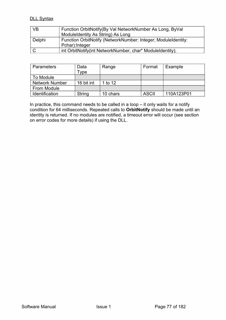
DLL Syntax
VB Function OrbitNotify(By Val NetworkNumber As Long, ByVal ModuleIdentity As String) As Long
Delphi Function OrbitNotify (NetworkNumber: Integer; ModuleIdentity: Pchar):Integer
C int OrbitNotify(int NetworkNumber, char* ModuleIdentity);
Parameters Data Type
Range Format Example
To ModuleNetwork Number 16 bit int 1 to 12From ModuleIdentification String 10 chars ASCII 110A123P01
In practice, this command needs to be called in a loop – it only waits for a notify condition for 64 milliseconds. Repeated calls to OrbitNotify should be made until an identity is returned. If no modules are notified, a timeout error will occur (see section on error codes for more details) if using the DLL.
Software Manual Issue 1 Page 77 of 182
15.5 ORBITPING
Module Type: All Except LE
Command Type: Special Broadcast
Description
This Orbit3 command interrogates the specified Orbit network to find a module connected on it. Like the OrbitNotify command, it returns the Module factory allocated identification of the un-addressed module found first. Once found, the module’s address should be set via the OrbitSetaddr command. Otherwise, the same module would be found again on subsequent OrbitPing commands.To find further modules, the OrbitPing command should be sent again, until no further modules are found.
The COM is written to simplify this process and sends multiple OrbitPing commands and sets addresses of modules found on the specified network. Therefore, it is only accessible via the COM.
Orbit modules that have had their address set by the OrbitSetaddr command will not respond to the OrbitPing command.
Note: that due to the way the OrbitPing command works, the order (address) in which the modules are found may be different each time.
Low Level Syntax
None available
RS232IM SyntaxDue to the higher level code required, the OrbitPing command is not recommended for use without the COM.
Software Manual Issue 1 Page 78 of 182

15.6 ORBITIDENTIFY
Module Type: All
Command Type: Addressed
Description
Returns the Orbit Module Identification Code, Device type, Software version and Stroke. This command is used to return basic information about the module.
Low Level Syntax
To Module <BREAK>,”I”,[000AAAAA]From Module “I”10 byte ID, 12 byte devicetype, 5 byte version, 2 byte stroke. //No Error
Notes: “I”, 10 byte ID, 12 byte devicetype, 5 byte version are ASCII, [000AAAAA] and 2 byte stroke are binary.
For multi-byte parameters byte order is 0(least significant), 1,2 3 etc.
Note: If an address to Identify has not be set, no reply will be sent. This will be returned as a timeout error (see section on error codes for more details) if using the DLL.
RS232IM SyntaxSend:• 0x02 = Command type• 0x1E = NumChars to receive• 0x02 = NumChars to send• 0x49 ( = “I” = Identify command)• 0x01 = address to talk to
Reply:• 0x00 = Status Byte• 0x1E = NumChars• “I” = Acknowledge Byte• 10 character identity• 12 character device type• 5 byte version• 2 byte (16 bit) integer stroke (Least Signiicant Byte sent first)
Software Manual Issue 1 Page 79 of 182
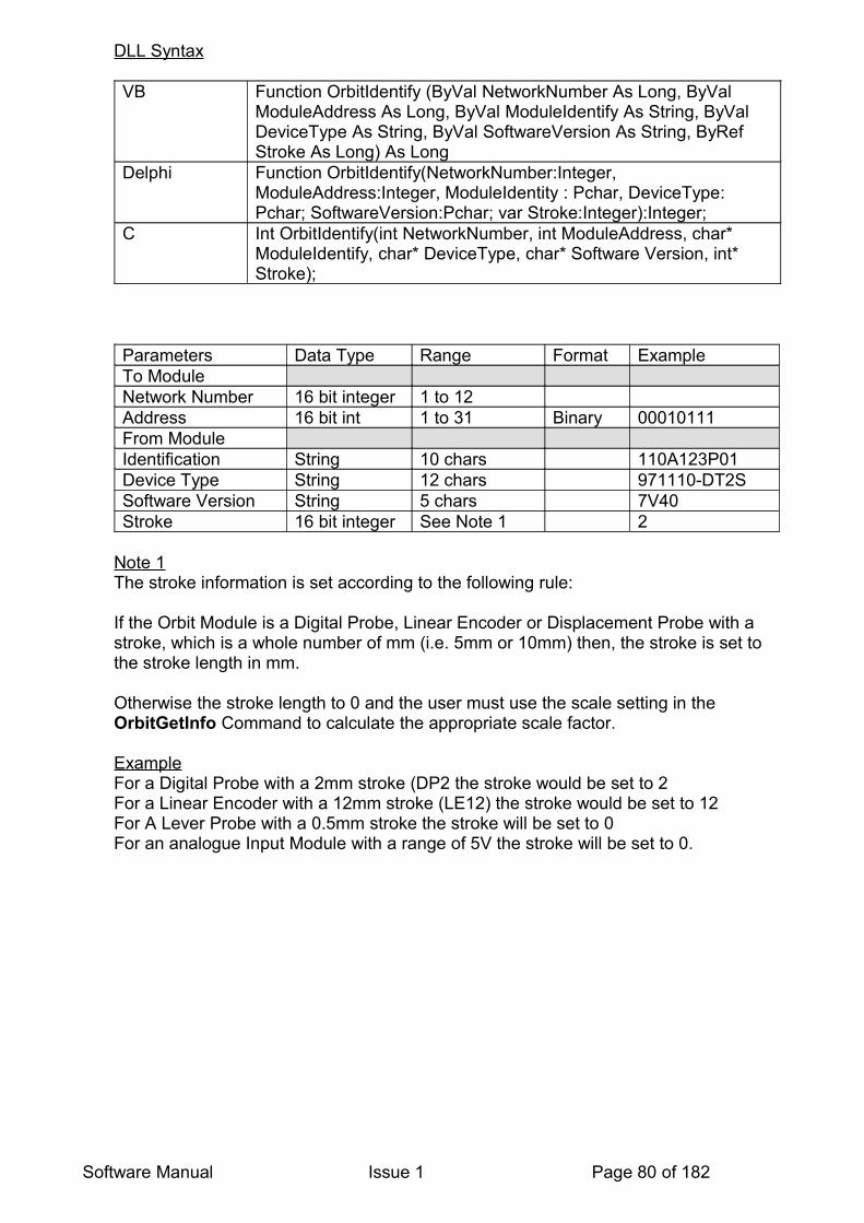
DLL Syntax
VB Function OrbitIdentify (ByVal NetworkNumber As Long, ByVal ModuleAddress As Long, ByVal ModuleIdentify As String, ByVal DeviceType As String, ByVal SoftwareVersion As String, ByRef Stroke As Long) As Long
Delphi Function OrbitIdentify(NetworkNumber:Integer, ModuleAddress:Integer, ModuleIdentity : Pchar, DeviceType: Pchar; SoftwareVersion:Pchar; var Stroke:Integer):Integer;
C Int OrbitIdentify(int NetworkNumber, int ModuleAddress, char* ModuleIdentify, char* DeviceType, char* Software Version, int* Stroke);
Parameters Data Type Range Format ExampleTo ModuleNetwork Number 16 bit integer 1 to 12Address 16 bit int 1 to 31 Binary 00010111 From ModuleIdentification String 10 chars 110A123P01Device Type String 12 chars 971110-DT2SSoftware Version String 5 chars 7V40Stroke 16 bit integer See Note 1 2
Note 1The stroke information is set according to the following rule:
If the Orbit Module is a Digital Probe, Linear Encoder or Displacement Probe with a stroke, which is a whole number of mm (i.e. 5mm or 10mm) then, the stroke is set to the stroke length in mm.
Otherwise the stroke length to 0 and the user must use the scale setting in the OrbitGetInfo Command to calculate the appropriate scale factor.
ExampleFor a Digital Probe with a 2mm stroke (DP2 the stroke would be set to 2For a Linear Encoder with a 12mm stroke (LE12) the stroke would be set to 12For A Lever Probe with a 0.5mm stroke the stroke will be set to 0For an analogue Input Module with a range of 5V the stroke will be set to 0.
Software Manual Issue 1 Page 80 of 182

15.7 ORBITGETINFO
Module Type: All
Command Type: Addressed
The OrbitGetinfo command is a powerful but complex command. It is recommended to use the Orbit COM library for accessing this command.
All Orbit products contain embedded information which is used to provide information about the specific Orbit Module. This includesModule TypeHardware TypeRange ValuesModule InformationCompatibility (Classic, Dynamic, High Speed)Units of measure (UOM)Counts per Unit of measure (CPUOM)Offset (OS)No of characters before decimal pointRead Types supportedMultiplier
This information is read back using the OrbitGetinfo command. See Using the Orbitgetinfo Command
Description
Returns information about the Orbit Module as described in the parameter list below. This command is only applicable to DP’s with Dynamic capability, do not try and use with old classic DP’s those without -1 In the part number.
Low Level Syntax
Network to Module: <BREAK>,”B”,[000AAAAA]From Module: “B”, 4 byte module type, 2 byte hardware type, 2 byte resolution, 32 byte module information. //No Error
Note1: “B”, 4 byte moduletype and 32 byte moduleinfo are all ASCII, all other parameters are binary.
Note: If an address to Getinfo has not be set, no reply will be sent. This will be returned as a timeout error (see section on error codes for more details) if using the DLL.
RS232IM SyntaxSend:• 0x02 = Command type• 0x29 = NumChars to receive• 0x02 = NumChars to transmit• 0x42 ( = “B” = Getinfo command)• 0x01 = address to talk to
Software Manual Issue 1 Page 81 of 182

Reply:• 0x00 = Status Byte• 0x29 = NumChars• “B” = Acknowledge Byte• 4 character Module type• 2 byte (16 bit) integer hardware type (Least Significant Byte sent first)• 2 byte (16 bit) integer resolution (Least Significant Byte sent first)• 32 character Module Info
DLL Syntax
VB Function OrbitGetinfo (ByVal NetworkNumber As Long, ByVal ModuleAddress As Long, ByVal ModuleType As String, ByRef HardwareType As Long, ByRef Scale As Long, ByVal ModuleInfo As String) As Long
Delphi function OrbitGetinfo (NetworkNumber: Integer; ModuleAddress: Integer; ModuleType: PChar; var HardwareType: Integer; var Scale: Integer; ModuleInfo: Pchar ): Integer
C int OrbitGetInfo (int NetworkNumber, int ModuleAddress, char* ModuleType, int* HardwareType, int* Scale, char* ModuleInfo);
Parameters Data Type Range ExampleTo ModuleNetwork Number 16 bit integer 1 to 12Address 16 bit integer 1 to 31 5
From ModuleModule Type String 4 chars “DP “Hardware type 16 bit integer 1 to XX (note 1) 150Scale 16 bit integer See Note 2 1000Module Information String 32 characters
(See note 3)D
Note1: Hardware Type (No longer supported)Used to describe the generic hardware configuration of the product See Appendix 1 to this document for hardware types. The hardware type can distinguish between for example buffered capability and non-buffered.
Note2: Scale InformationThe scale information is used to define what the output of the module is in real terms. The following rules apply.
For Linear Encoder set to 5 (Meaning 0.05µm = 1 count)For Encoder Input Module set to 1 (application software will need to handle this module)
For Digital Probes where stroke (See OrbitIdentify) is not set to 0, scale is set to 0 and the scale is calculated from the stroke information
Software Manual Issue 1 Page 82 of 182

If stroke is set to zero then scale is set as below:
Transducer modules with stroke less than 1mm, scale is set to the equivalent of stroke in µm.
AIM set scale to full range input in mV or mA.
Examples
Module Module Stroke or Range Scale UnitsLever Probe 0.5mm 500 µmAIM 0-5V 5000 mVAIM -10 to + 10 V (20V FRO) 20000 mVAIM 4-20mA (16mA FRO) 16 mA
FRO = Full Scale Reading
Software Manual Issue 1 Page 83 of 182

15.8 ORBITGETSTATUS
Module Type: All
Command Type: Addressed
Description
Will return the status of an Orbit module including any error codes. This also resets certain errors (for example overspeed error for LE).
Low Level Syntax
Network to Module <BREAK>,”G”, [000AAAAA]Module to Network “G”, 1 byte error code, 2 byte status
Note “G” in ASCII. All other parameters binary, with LS byte transmitted first.
Note: If an address to Getstatus has not be set, no reply will be sent. This will be returned as a timeout error (see section on error codes for more details) if using the DLL.
RS232IM SyntaxSend:• 0x02 = Command type• 0x04 = NumChars to receive• 0x02 = NumChars to transmit• 0x47 ( = “G” = Getstatus command)• 0x01 = address to talk to
Reply:• 0x00 = Status Byte• 0x04 = NumChars• “G” = Acknowledge Byte• 1 byte (8 bit) Error Code• 2 byte (16 bit) status.
DLL Syntax
VB Function OrbitGetstatus (ByVal NetworkNumber As Long, ByVal ModuleAddress As Long, ByRef ErrorCode As Long, ByRef Status As Long) As long
Delphi Function OrbitGetstatus (NetworkNumber :Integer; ModuleAddress :Integer; var ErrorCode :Integer; var Status :Integer): Integer
C int OrbitGetstatus (int NetworkNumber , int ModuleAddress, int* ErrorCode, int* Status);
Software Manual Issue 1 Page 84 of 182

Parameters Data Type Range ExampleTo ModuleNetwork Number 16 bit integer 1 to 12Address 16 bit integer 1 to 31 5
From ModuleError Code Integer 16 bitsStatus Integer 16 bits
Return is 0 if the command has been successful or errors code if not. The value of the data in the status bytes varies with the module type and is explained in the following:
15.8.1 Digital Probe - Status Format
Byte 1 (sent after byte 0) Byte 0 (sent first)
D7 D6 D5 D4 D3 D2 D1 D0 D7 D6 D5 D4 D3 D2 D1 D0TR ST NU NU NR C C C NU RT RT RT RT RT RT RT
Default values0 0 0 0 1 0 0 0 0 0 0 0 0 0 0 0
Flag meaning when set:
TR Orbit Module triggered (after OrbitAcquire and OrbitDifference commands), will be set to 1 when the module is triggered via OrbitTrigger or OrbitStartdiff or started Buffered Mode Readings.
ST Orbit Module stopped (after OrbitAcquire and OrbitDifference commands), will be set to 1 after the module is stopped via OrbitAcquire stop or OrbitStopdiff or stopped Buffered Mode Readings.
NR New reading available. If the module is read using OrbitRead commands this flag is set to 0 and only set to 1 once a new value is ready to be read from the module. This flag can be used to stop a fast network reading the same value more than once. To do this continually check the status byte by calling OrbitGetstatus, and only read the module result if the NR = 1.Note that NR is not set in buffered mode (always NR = 0)
RT No.of readings taken (OrbitAcquire mode).NU Not used and set to 0CCC 000 Normal mode
001 OrbitDifference mode010 OrbitAcquire mode011 Sync mode100 Sample Mode (Buffered)101 Capture Mode (Buffered)110 – 111 Reserved
If OrbitRst or OrbitClr is used all status bytes will be set to their default values. This command also clears the Orbit Module ‘hard’ error flag if set, see Error Codes section for details.Note: the OrbitAcquire mode is no longer supported.
Software Manual Issue 1 Page 85 of 182

15.8.2 Linear Encoder - Status Format
This command is the same as for Digital Probe except the 16 bit status word returned has a different meaning.
Byte 1 (sent after byte 0) Byte 0 (sent first)
D7 D6 D5 D4 D3 D2 D1 D0 D7 D6 D5 D4 D3 D2 D1 D0TR ST NU NU NR NU NU NU NU NU RS RR RF D NU NU
Default values0 0 0 0 1 0 0 0 0 0 0 0 0 0 0 0
Flag meaning when set:
TR Orbit Module triggered (after OrbitDifference commands), will be set to 1 when the module is triggered via OrbitStartdiff
ST Orbit Module stopped (after OrbitDifference commands), will be set to 1 after the module is stopped via OrbitStopdiff.
NR New reading available. If the module is read using OrbitRead2 commands this flag is set to 0 and only set to 1 once a new value is ready to be read from the module. This flag can be used to stop a fast network reading the same value more than once. To do this continually check the status byte by calling OrbitGetstatus, and only read the module result if the NR = 1.
D Indicates direction of count, 1= positive or 0 = negative (cnage using OrbitDirection command)
RS 1 = looking for Ref MarkRF 1 = Ref Mark foundRR 1 = Ref Mark read.NU Not used and set to 0
If OrbitRst, OrbitClr or OrbitPreset is used both status bytes will be set to default values.
If an overspeed (LE only) has occurred OrbitGetstatus will return both the relevant error code and the status of the module just before the overspeed occurred. All status flags will then be set to default values and the module reading will be reset to zero. The next OrbitGetstatus will return the new status of the module, if no errors have occurred or modes entered the error code and status bytes will be at their default values. The Module will retain its network address.
Software Manual Issue 1 Page 86 of 182

15.8.3 Encoder Input Module (EIM) - Status FormatA call to the OrbitGetstatus function will return a 16-bit status value, the flag meanings are similar to those on the Linear Encoder but, unlike the Linear Encoder, the EIM handles the Reset and Preset on Reference mark internally in hardware.
Byte 1 (MSB) Byte 2 (LSB)D7 D6 D5 D4 D3 D2 D1 D0 D7 D6 D5 D4 D3 D2 D1 D0NU NU NU NU NU NU NU NU NU NU RS RR RF NU NU NU
Flag Meaning when set.RS = Looking for reference marker.
Set when OrbitSetmode Reset / Preset counter on reference pulse (Mode 75, M_Arg 1,2,3 & 4) is called. Cleared when OrbitSetmode Do nothing (Mode 75, M_Arg 0) is called or when Reset / Preset counter on first reference pulse (Mode 75, M_Arg 3 & 4) is active and Reference mark has been 'Read'.
RF = Reference mark found. Set when Reference mark has been passed Cleared when the Reference mark has been 'Read' via the OrbitRead2 command
RR = Reference mark has been 'Read'. Set when the Reference mark has been 'Read' via the OrbitRead2 command Cleared when OrbitSetmode - Mode 75 (M_Arg 1 & 2) is active and new Reference mark found after previous Reference mark has been 'Read' NU = Not used. (Currently set to 0)
The Default State of all flags is 0 at power on
15.8.4 Digimatic Interface Module (DIM) – Status Format
handles the Reset and Preset on Reference mark internally in hardware.
Byte 1 (MSB) Byte 2 (LSB)D7 D6 D5 D4 D3 D2 D1 D0 D7 D6 D5 D4 D3 D2 D1 D0NU NU NU NU NR C C C NU NU RU NU NU NU NU TO
Default value at power on (if the gauge is connected and operating).
Byte 1 (MSB) Byte 2 (LSB)D7 D6 D5 D4 D3 D2 D1 D0 D7 D6 D5 D4 D3 D2 D1 D00 0 0 0 1 0 0 0 0 0 0 0 0 0 0 0
i.e. 0x0800 Hex.
Flag meaning when set:
RA - Reading available.
Software Manual Issue 1 Page 87 of 182

Set when a valid reading is in the buffer. Cleared when module is waiting for a gauge data transfer to complete.
TO - Gauge timeout. Set when a gauge data transfer has been requested and the gauge has failed to respond, this will occur if the gauge is disconnected or switched off.
C - Mode: 000 Read Gauge continuously (default) 001 Read Gauge when ‘Data send’ button pressed 010 Read Gauge when OrbitControl (Action = 30) received
See OrbitSetmode for detailed description of Digimatic Interface Module modes.
NR - New reading. Set when gauge data is transferred into the modules’ internal register, cleared when the register is read via the OrbitRead2 command.
15.8.4.1 Status Word Examples
DIM mode = Read Gauge continuously
Status Word Flags set CommentsDecimal Hex0 0x0000 None Waiting for new reading from gauge1 0x0001 TO Gauge disconnected or switched off2048 0x0800 NR New reading transferred from gauge
DIM mode = Read Gauge when ‘Data send’ button pressed.
Status Word Flags set CommentsDecimal Hex256 0x0100 None Waiting for new reading from gauge257 0x0101 TO Gauge disconnected or switched off2304 0x0900 NR New reading transferred from gauge
DIM mode = Read Gauge when OrbitControl (Action = 30) received
Status Word Flags set CommentsDecimal Hex512 0x0200 None Waiting for new reading from gauge513 0x0201 TO Gauge disconnected or switched off2560 0x0A00 NR New reading transferred from gauge
Software Manual Issue 1 Page 88 of 182
15.9 ORBITSETMODE
Module Type: Digital Probe, AIM, EIM, DIOM, DIM
Command Type: Addressed
Description
Sets the Orbit Module up for Different Operating Modes – including: resolution, averaging, dynamic, buffered. This is a complicated command and is defined below.
Low Level Syntax
Network: to Module <break>,”V”,[000AAAAA],Mode, Mode_ArgFrom Module “V”,[000AAAAA] No ErrorFrom Module “!”,Error Code If in error (e.g. incompatible mode)
Where V is the command character for Set Mode (1 byte) in ASCII, [000AAAAA] is the Orbit Address 1 to 31 (one byte) Mode is the mode to set (two bytes – in binary HEX, LSB first) Mode_Arg is the argument – contains any parameters for the desired mode (two bytes – in binary HEX, LSB first)
! is the command character for a module error (1 byte) in ASCII Error Code is the Orbit Error Code (one byte)
Note: If an address to SetMode has not be set, no reply will be sent. This will be returned as a timeout error (see section on error codes for more details) if using the DLL.
RS232IM SyntaxSend:• 0x02 = Command type• 0x02 = NumChars to receive• 0x06 = NumChars to transmit• 0x56 ( = “V” = Setmode command)• 0x01 = address to talk to• Mode (Least Significant Byte)• Mode (Most Significant Byte)• Mode Arg (Least Significant Byte)• Mode Arg (Most Significant Byte)
Reply:• 0x00 = Status Byte• 0x02 = NumChars• “V” = Acknowledge Byte• 1 byte (8 bit) Orbit address.
Software Manual Issue 1 Page 89 of 182
DLL Syntax
VB Function OrbitSetmode (ByVal Network Number As Long, ByVal Module Address As Long, ByRef Mode As Long, ByRef M_Arg As Long) As Long
Delphi function OrbitSetmode (NetworkNumber:Integer; ModuleAddress:Integer; var Mode:Integer;M_Arg : Integer):Integer;
C int OrbitSetmode (int NetworkNumber, int ModuleAddress, int*Mode, int*M_Arg)
In each case the returned value is the error status (0=no error)
DLL parameters
Parameters Data Type Range ExampleNetwork Number 16 bit integer 1 to 12 2Address 16 bit integer 1 to 31 5Mode 16 bit integer See table belowModeargument 16 bit integer See table below
Mode and Mode_Arg
These parameters are used to set up the Orbit Module
Mode(Dec)
Mode Description Mode_Arg(Dec)
SupportedBy
0 Standard mode (Default) DP, EIM10 Reserved for synchronized Mode
Unbuffered. (not implemented)DP
11 synchronized Mode Buffered (implemented in buffered DP)
DP
12 Reserved13 Reserved20 Reserved for Sample Mode Unbuffered
(not implemented)21 Sample Mode Buffered (implemented in
buffered DPDP
30 Capture (Linear Encoder Only) (not implemented)
40 Prepare module for 187.5kB/s Orbit operation
DP,AIM,EIM
41 Prepare module for 1.5MB/s Orbit operation
DP,AIM,EIM
50 Set Averaging (For relationship between bandwidth and Mode_Arg values refer to Programmable Measurement Bandwidth Section)
1,2,4,8,16,32,64,128, 256
DP,AIM
51 Set Resolution(14bit, 16bit or 18bit mode resolution)
14, 16, 18 DP,AIM
Software Manual Issue 1 Page 90 of 182

60* Prepare module for dynamic 1k mode - 977rdgs/s, 1.024us frame time, max 31 modules
DP,AIM,EIM
61* Prepare module for dynamic 2k mode - 1954rdgs/s, 512us frame time, max 16 modules
DP,AIM,EIM
62* Prepare module for dynamic 4k mode - 3906rdgs/s, 256us frame time, max 8 modules
DP,AIM,EIM
70 Set Input Type EIM71 Set quadrature mode EIM75 Action to take when Reference pulse is
detectedEIM
76 Transmit Dynamic Sync pulse every N encoder pulses
EIM
77 Transmit OrbitControl (Action = Sample) every N encoder pulses
EIM
78 Load HoldoffCount EIM90 DIM Reading Mode DIM
*Modules must be set to 1.5MB/s Orbit operation for commands 60, 61 and 62 to operate.
Detailed Description of Modes
Mode(Dec)
Description
0 Normal ModeIn this mode the Digital Module are free running, with readings taken every 4ms. This is the default mode. The M_Arg value is ignored
11 Sync mode (buffered) – DPReadings are taken at a rate determined by M_Arg. Each new reading is placed in a buffer in the module and the buffer pointer is incremented. The Digital Probe buffer can store up to 3000 readings. Readings are obtained from the Digital Probe via the OrbitReadbuffer1 command.
Sync operation is initiated via the OrbitControl command (Action = Start Sync mode), which synchronizes all modules set into modes 1 or 2.
The OrbitControl command (Action = Stop Sync mode) stops the module taking further readings.Note: In Classic DP’s there is a delay of 12ms before the first reading is put into the buffer.
To clear the current mode and set the module to its default condition call the OrbitSetmode command ensuring that M_Arg is set to 0. If a call is made to OrbitSetmode with M_Arg set to the mode that the module is currently in, the internal buffer is cleared.
Software Manual Issue 1 Page 91 of 182

M_Arg (Delay) - is in Orbit Timing Units, where 1 OTU = 102.4us. The Digital Probe delay must be specified in multiples of 40 OTU’s.
21 Sample Mode (buffered) DPA reading is taken each time the module receives the OrbitControl command (Action=Sample). Each new reading is placed in a buffer in the module and the buffer pointer is incremented. The Digital Probe buffer can store up to 3000 readings. Readings are obtained from the Digital Probe via the OrbitReadbuffer1 command.The M_Arg value is ignored.
4041
Prepare module for 187.5kB/s Orbit operationPrepare module for 1.5MB/s Orbit operationSet module Baud rate command. If module is not capable of this rate, the command will fail (return error code or timeout). Default baud rate at power on or after an OrbitRst command will be 187.5kB/s. The reply from the module will always be at the rate the network was set to before the OrbitSetmode (Mode 40 or Mode 41) command. The broadcast command OrbitControl (with action = 10) will be used to switch the modules to the prepared rate.
It will be the responsibility of the driver software (DLL or COM) to ensure that all modules on the network are capable of the required Orbit Baud rate before issuing the OrbitControl (action = 10) command
Note: The M_Arg parameter is ignored. For COM based applications use IOrbitNetwork ComSpeed property
50 Set Module Reading AverageThe M_Arg parameter is used to set the reading average. The default averaging is 16 on power up.
60
61
62
Prepare module for dynamic 1k mode - 977rdgs/s, 1.024us frame time, max 31 modules
Prepare module for dynamic 2k mode – 1954rdgs/s, 512us frame time, max 16 modules
Prepare module for dynamic 4k mode – 3906rdgs/s, 256us frame time, max 8 modules
Module must be set to 1.5MB/s Orbit operation for this command to be successful, the M_Arg value is ignored.
The broadcast command OrbitControl (with action = 20) will be used to switch the modules to the prepared dynamic mode. It will be the responsibility of the driver software (DLL or COM) to ensure that all modules set to dynamic operation are set to the same mode before issuing the OrbitControl (action = 20) command. All modules in the dynamic group must be set to the same mode.
70 Set Input Type –EIMThe EIM can accommodate both differential and single ended
Software Manual Issue 1 Page 92 of 182

encoders, use this command to set the module for the appropriate type.
Input Type M_Arg=0 DifferentialM_Arg=1 Single ended In single ended mode, connect encoder signals to A+, B+ and Ref+. Leave A-, B- and Ref- inputs unconnected.
The Encoder module defaults to '0' (Differential) at power up.
71 Set Quadrature Mode EIMThe encoder can be set to provide interpolation of the incoming square waves from an incremental encoder.These square waves are connected to the A and B inputs of the EIM The level of interpolation is x1, x2 and x4. These are set using the M_Arg Values as below:
Quadrature ModeM_Arg =0 X1M_Arg = 1 X2M_Arg = 2 X4
There are two other modes which the EIM can be set to. In these modes, the EIM acts as a simple Up-Down counter.Do not use these modes with incremental encoder type devices.M_Arg=3 CountAB Configuration 1 A = Up count input, B = High Configuration 2 B = Down count input, A = HighThe count increments / decrements on the Low to High edge of the input signal.The unused input must be kept High when the edge occurs. This can be achieved by connecting the unused input to the +5V line.
M_Arg=4 CountDIR A = Up count input, B = count direction [Low = UP, High = DOWN] B may only switch when A is High.
The EIM defaults to '0' (x1) at power up.
75 Set Reference actionThe EIM can be set to take various actions when the encoder reference pulse is detected.
M_Arg (RefAction) = 0 Do nothingM_Arg (RefAction) = 1 Reset counter every time reference pulse is detectedM_Arg (RefAction) = 2 Preset counter every time reference pulse is detectedM_Arg (RefAction) = 3 Reset counter first time reference pulse is detectedM_Arg (RefAction) = 4 Preset counter first time reference pulse is detected
Software Manual Issue 1 Page 93 of 182
M_Arg (RefAction) = 5 Reset counter first time reference pulse is detected & enable mode 76 / 77M_Arg (RefAction) = 6 Preset counter first time reference pulse is detected & enable mode 76 / 77
If reset counter is chosen the module will ignore the OrbitPreset command.If preset counter is chosen, the required preset value can be written to the module via the OrbitPreset command. If OrbitPreset is performed after mode 75 then the current reading will be unaffected until the encoder Reference pulse is detected.If OrbitPreset is NOT performed after mode 75 then the current preset value (written to the module via the most recent OrbitPreset command) is used. If the OrbitPreset command has not been used since OrbitRst then this value will be 0.
The EIM defaults to '0' (Do nothing) at power up.
76 Set Transmit syncThe EIM can be set to transmit Dynamic Sync pulse(s) every N encoder pulses (counts).(TxSync property)
M_Arg(PulsesPerSync) = positive number between 1 and 65,535
M_Arg=0 will clear this mode of operation.The EIM defaults to '0' at power up.
Note.The module must be set to 1.5MBaud before setting the module to this mode. Also, the module must be set to the same dynamic mode as the rest of the modules in the dynamic group.
77 Set Transmit sampleThe EIM can be set to transmit OrbitControl (Action = Sample) every N encoder pulses.(TxSample property)
M_Arg(PulsesPerSample) = positive number between 1 and 65,535
M_Arg=0 will clear this mode of operation.The EIM defaults to '0' at power up.
Note.The other modules on the network must support Sample mode (buffered) commands.
78 Load Holdoff CountM_Arg = Required counter valueUsed before setting Modes 76 or 77 to set the counter value at which the first Sync pulse (or Sample) will be sent. Subsequent sync pulses will be sent every N encoder pulses
Software Manual Issue 1 Page 94 of 182

** Use OrbitSetmode normal (Mode=0, M_Arg =don’t care) to clear this condition.
Note: At power on the module mode(s) default to the state described by Mode_Arg=0
90 DIM Reading Mode
Comments
To clear the current mode call OrbitSetmode with Mode set to 0. Calls made to OrbitSetmode with the mode = modules current mode will clear any buffers
15.9.1.1 OrbitSetmode & DIM
Syntax: OrbitSetmode (NetworkNumber; ModuleAddress, Mode, M_Arg)
Mode and M_Arg are used to set the gauge triggering as below.
Mode 90 Set Gauge Reading Mode [GaugeRdgMode]M_Arg = 0 Read Gauge continuously [rdContinuous] The gauge is continuously triggered and the resulting data is stored in an internal register ready to be read via the OrbitRead2 command. This is the power on default setting.M_Arg = 1 Read Gauge when ‘Data send’ button pressed [rdOnSwitch] The gauge ‘Data send’ button is continuously monitored for a button press. When the button is pressed the module triggers the gauge and the resulting data is stored in an internal register ready to be read via the OrbitRead2 command. M_Arg = 2 Read Gauge when OrbitControl (Action = 30) received [rdOnControl]
The module continuously monitors the Orbit network for an OrbitControl command. When an OrbitControl command (with Action = 30) is received the module triggers the gauge and the resulting data is stored in an internal register ready to be read via the OrbitRead2 command.
15.10 ORBITCONTROL
Module Type: Digital Probe, AIM, EIM, DIOM, DIM
Command Type: Broadcast – no reply is expected for this command
Description
The OrbitControl is a broadcast command that sets modules to modes 10, 11, 20 and 21. This is typically used to start or stop modules operating in a mode individually set by the OrbitSetmode command.
Low Level SyntaxNetwork: to Module <break>,”W”,Action
From Module No response
Where “W” is the command character for OrbitControl (1 byte) in ASCII Action is as below (one byte) in binary
Software Manual Issue 1 Page 95 of 182

RS232IM SyntaxSend:• 0x00 = Command type• 0x02 = NumChars to send• 0x57 (= “W”)• 1 byte action (e.g. 0x01 = Start synchronized Mode - Buffered DP)
There is no reply to this command.
DLL Syntax
VB Function OrbitControl (ByVal Network Number As Long, ByVal Action As Long
Delphi Function OrbitControl (NetworkNumber:Integer; Action:Integer) :Integer;
C int OrbitControl (int NetworkNumber, int*Action)
Parameters Data Type Range ExampleTo ModuleNetwork Number 16 bit integer 1 to 12 2Action 16 bit integer See table below 2
These actions are used to set the Orbit Module
Action values Action0 Clear Internal Buffers1 Start synchronized Mode (Buffered DP)2 Stop synchronized Mode (Buffered DP)3 Sample 10 Switch Module to prepared baud Rate.
Modules must have been first prepared with the OrbitSetmode command
20 Switches modules to the dynamic mode. Modules must have been prepared for dynamic mode via OrbitSetmode modes.. Modules will transfer readings in conjunction with sync pulses from the network controller.
21 Terminates dynamic mode for any modules that have been started by action 20, modules revert back to non dynamic mode
30 Samples a reading of the DIM in reading mode 2
15.10.1 OrbitControl & DIM
Action = 30 Trigger Gauge [TriggerGauge]
This command will make the module trigger the Gauge to take a reading if the module has previously been set to Mode 90, M_Arg 2 (see OrbitSetmode & DIM).
Software Manual Issue 1 Page 96 of 182

15.11 ORBITREAD1
Module Type: AIM, DP, Displacement
Command Type: Addressed
Description
Returns a 16 bit reading from an Orbit Module, Readings are updated at fixed intervals. Use the OrbitRead2 command for reading Linear Encoders, DIM, EIM and higher resolution modes (16 or 18 bit Digital Probe).
Note that this command is not available in buffered mode (sync or sample) .
Low Level Syntax
Network:to Module <break>,”1”,[000AAAAA],From Module “1”, 2 byte probe position/module output //No ErrorFrom Module “!”,Error Code //If in error. Ignore subsequent bytes
Note “1” or ‘!’ is in ASCII, probe position/module output is binary
RS232IM SyntaxSend:• 0x02 = Command type• 0x03 = NumChars to receive• 0x02 = NumChars to transmit• 0x31 ( = “1” = Read1 command)• 0x01 = address to talk to
Reply:• 0x00 = Status Byte• 0x03 = NumChars• “1” = Acknowledge Byte• 2 byte (16 bit) integer reading (Least Significant Byte sent first)
DLL Syntax
VB Function OrbitRead1 (ByVal NetworkNumber As Long, ByVal ModuleAddress As Long, ByRef Reading16 As Long) As Long
Delphi Function OrbitRead1(NetworkNumber:Integer; ModuleAddress:Integer; var Reading16:Integer):Integer;
C int OrbitRead1 (int NetworkNumber, int ModuleAddress, int*Reading16);
Parameters Data Type Range ExampleTo ModuleNetwork Number 16 bit integer 1 to 12 2Module Address 16 bit integer 1 to 31 2From ModuleReading 16 bit integer 0 to 16384
Software Manual Issue 1 Page 97 of 182
The return value is either the module reading or an error code if a reading cannot be taken. (refer to section on Error codes)
Digital Probes and most Orbit Modules have a calibrated range and are by default 14-bit resolution on power-up. See Orbit Information Data section for more details on handling the returned measurements.
Software Manual Issue 1 Page 98 of 182
15.12 ORBITREADBUFFER1
Module Type: Digital Probe, AIM, DIOM
Command Type: Addressed
Description
Reads a buffered Orbit Modules buffer contents as a two byte sequence. This command is used to read the buffer in buffered mode Digital Probes.
Low Level Syntax
Network:to Module <BREAK >,”2”,[000AAAAA],From Module “2”, 1 byte length, array of 2 byte readings (max 64 bytes), 1 byte checksumFrom Module “!”, 2, Error Code, CheckSum //if in errorNote: If in error the checksum is still sent along with the error code, meaning the byte length is fixed at 2Note: “2” or “!” is in ASCII, all else binaryNote: 2 byte readings are sent Least Significant byte followed by Most Significant byte.
RS232IM SyntaxSend:• 0x0D = Command type (Variable length reply)• 0x02 = NumChars to receive• 0x32 ( = “2” = ReadBuffer1 command)• 0x01 = address to talk to
Reply (OK):• 0x00 = Status Byte• NumChars to follow• ‘2’ = Acknowledge Byte• Reading1 (LS Byte – Byte 0)• Reading1 (MS Byte – Byte 1)
…...........................• ReadingN (LS Byte – Byte 0)• ReadingN (MS Byte – Byte 1)• Checksum Byte
Where N denotes the number of reading sent back. Note that a maximum of 32 readings can be returned at a time.DLL Syntax
VB Function OrbitReadBuffer1 (ByVal NetworkNumber As Long, ByVal ModuleAddress As Long, ByRef Number of Readings As Long, ByRef ReadingBuffer16 As Long) As Long
Delphi function OrbitReadBuffer1 (NetworkNumber:Integer; ModuleAddress:Integer; var NumberOfReadings:Integer; var ReadingBuffer16:Integer):Integer;
C int OrbitReadBuffer1 (int NetworkNumber, int ModuleAddress, int* Number of Readings, int*ReadingBuffer16[]);
Software Manual Issue 1 Page 99 of 182

The module responds to these commands with up to 32 readings on a First In/First Out (FIFO) basis. If there are more than 32 readings in the buffer this process will need to be repeated until the buffer has been emptied. The buffer read pointer is re-positioned each time the buffer is read.
If at any stage the buffer becomes full the transfer of readings into the buffer is halted.
If at any stage the buffer becomes full the transfer of readings into the buffer is halted. At this point the ‘stopped’ flag (D6 byte 1, in the status word) is set. Under this condition the module responds to OrbitReadbuffer1 and OrbitGetstatus commands with a “buffer full” error message.
The next OrbitReadbuffer1 command will clear the “buffer full” condition, and return the first set of readings. The remaining contents of the buffer can be read via subsequent calls of the OrbitReadbuffer1 command (reading up to 32, 2 byte readings). The OrbitReadbuffer1 command will eventually return 0 bytes back. This indicates that the buffer is empty. A subsequent OrbitReadbuffer1 command will reset the module out of buffered mode and return a BUFFER_EMPTY error code. A further OrbitReadbuffer1 command will return a NOT_IN_BUFFERED_MODE error.
Note:1. The Length byte (Network: from module) indicates the number of bytes to follow
and is used by the driver to calculate the number of bytes to expect.
2. The 8 bit checksum (Network: from module) is the 2’s complement of the sum of all bytes of the array of 2 byte readingsand the length byte = NOT(Sum of all bytes) + 1
3. The Integer (2 bytes) number range = +/- 32,768with Digital Probe, overrange and underrange are returned as -1 and -32,768 respectively.
Software Manual Issue 1 Page 100 of 182

15.13 ORBITREAD2
Module Type: Linear Encoder, Digital Probe, AIM, EIM, DIM
Command Type: Addressed
Description
Returns a 32 bit reading (higher precision than Orbit Read1) from an Orbit Module. Readings are updated at fixed intervals. For more details, refer to the Detailed Information Section in this document.Note: This command does not work whilst the module is in Difference Mode.
Low Level Syntax
Network:to Module <break>,”L”,[000AAAAA],From Module “L”, 4 byte probe position/module output //No ErrorFrom Module “!”,Error Code //If in error. Ignore subsequent bytes
Note “L” or “!” is in ASCII, probe position/module output is binary
RS232IM SyntaxSend:• 0x02 = Command type• 0x05 = NumChars to receive• 0x02 = NumChars to transmit• 0x4C ( = “L” = Read2 command)• 0x01 = address to talk to
Reply:• 0x00 = Status Byte• 0x05 = NumChars• “L” = Acknowledge Byte• 4 byte (32 bit) integer reading (Least Significant Byte sent first)
DLL Syntax
VB Function OrbitRead2 (ByVal NetworkNumber As Long, ByVal ModuleAddress As Long, ByRef Reading32 As Long) As Long
Delphi Function OrbitRead1(NetworkNumber:Integer; ModuleAddress:Integer; var Reading32:Integer):Integer;
C int OrbitRead1 (int NetworkNumber, int ModuleAddress, int*Reading32);
Parameters Data Type Range ExampleTo ModuleNetwork Number 16 bit integer 1 to 12 2Module Address 16 bit integer 1 to 31 2From ModuleReading 32 bit integer
Software Manual Issue 1 Page 101 of 182

The return value is either the module reading or an error code if a reading cannot be taken. (refer to section on Error codes).
CommentsReturns a reading from the Orbit Module. Readings are updated at fixed intervals.
Linear Encoder has an internal reading update time of 1 ms. This means that a new reading is available every 1 ms.
If there is a fault or condition where a reading is not possible, such as overspeed, an error code sequence is returned instead of the reading. Refer to the Error Codes section for details.The Linear Encoder has a fixed resolution regardless of stroke, each ‘bit’ represents a fixed distance (other probe or module types may have a fixed stroke but no fixed resolution per bit).The Incremental position or reading is returned by OrbitRead2 and OrbitReaddiff2 commands, but must be multiplied by the resolution depending on probe type to give a reading in mm.
Incremental position = N x resolution
Where N is the returned reading (rdLong& etc.). The probe stroke can be obtained by using the OrbitIdentify command and probe resolution can be given by the OrbitGetinfo command.
This command will return the reference mark position if OrbitRefmark is set and the probe reference mark is passed, or clear OrbitRefmark if the probe reference mark has not been passed. Refer to OrbitRefmark command for details.
Software Manual Issue 1 Page 102 of 182
15.14 ORBITCLR
Module Type: AIM, DP, Displacement, EIM, LE, DIOM, DIM
Command Type: Addressed
Description
Performs software reset on an Orbit Module, The module will then need to be re-addressed. Allow approximately 0.5secs to complete the command. Note: This is an addressed version of the OrbitRst command.
Low Level Syntax
Network: to Module <break>,”C”,[000AAAAA],From Module “C”, [000AAAAA]
Note “C” is in ASCII, [000AAAAA] is in binary
RS232IM SyntaxSend:• 0x02 = Command type• 0x02 = NumChars to receive• 0x02 = NumChars to transmit• 0x43 ( = “C” = Clr command)• 0x01 = address to talk to
Reply:• 0x00 = Status Byte• 0x02 = NumChars• “C” = Acknowledge Byte• 1 byte (8 bit) Orbit address.
DLL Syntax
VB Function OrbitClr (ByVal NetworkNumber As Long, ByVal ModuleAddress As Long,) As Long
Delphi Function OrbitClr (NetworkNumber:Integer; ModuleAddress:Integer):Integer;
C int OrbitClr (int NetworkNumber, int ModuleAddress);
Parameters Data Type Range ExampleTo ModuleNetwork Number 16 bit integer 1 to 12 2Module Address 16 bit integer 1 to 31 2
This command will perform a software reset on an addressed Orbit module which will need to be re-addressed before it can be used again. It is vital to allow 0.5s before attempting to re-address any module cleared with the OrbitClr command. It will clear
Software Manual Issue 1 Page 103 of 182

previously set values from modules previously configured with the following commands.
Clear address (cancels OrbitSetaddr)Orbit Module will now respond to OrbitNotify commandClear OrbitAcquire command status (single sample no delay)Clear OrbitDifference command status (don’t record difference)Reset Orbit Module software
An OrbitClr command effectively removes a module from the network. To re-instate the module, the network must be in low speed (187.5kBaud).This is because this command will reset the module back to normal Orbit Baud rate (187500 bps), therefore a network in high-speed mode cannot re-instate a module removed by the OrbitClr command. It should switch to normal speed first.
15.15 ORBITRST
Module Type: All module types
Command Type: Broadcast – no reply is expected for this command
Description
Performs software reset on all Orbit Modules on a network at the same time (See OrbitClr command for details). The modules will then need to be re-addressed. Allow approximately 0.5secs to complete before attempting further commands.This command will reset all modules back to normal Orbit Baud rate (187500 bps)
Low Level Syntax
Network: to Module <break>,”R”,[00000000],From Module No response]
Note “R” is in ASCII, [00000000] is in binary
RS232IM SyntaxSend:• 0x00 = Command type• 0x02 = NumChars to send• 0x52 (= “R”)• 0x00
There is no reply to this command.
DLL Syntax
VB Function OrbitRst (ByVal NetworkNumber As Long) As LongDelphi Function OrbitClr (NetworkNumber:Integer;):Integer;
C int OrbitClr (int NetworkNumber,);
Software Manual Issue 1 Page 104 of 182

Parameters Data Type Range ExampleTo ModuleNetwork Number 16 bit integer 1 to 12 2
This command will perform a software reset on all Orbit Modules on a network which will need to be re-addressed before it can be used again. It is vital to allow 0.5s before attempting to re-address any module cleared with the OrbitRst command. It will clear previously set values from modules previously configured with the following commands.
Clear address (cancels OrbitSetaddr)Orbit Module will now respond to OrbitNotify commandClear OrbitAcquire command status (single sample no delay - no longer supported).Clear OrbitDifference command status (don’t record difference)Reset Orbit Module software
An OrbitRst command puts the whole network back to low speed mode and clears any module set up with the OrbitSetmode command back to default conditions.
Note that although some Orbit Modules can operate at different data rates, Orbit Modules set to different speeds cannot be used on the same network. To set the Orbit Module Baud rate a OrbitRst command must be sent to the network after power up and before any other command.The OrbitRst command character is analysed by the receiving module(s) and the Baud rate is set accordingly.
Software Manual Issue 1 Page 105 of 182

15.16 ORBITDIFFERENCE
Module Type: All modules
Command Type: Addressed
Description
This command sets up the Orbit module to take readings continually once started using the OrbitStartdiff command. The module will then store depending on module type:
maximum Reading (2 bytes)minimum reading (2 bytes)Sum of all readings (5 bytes)Number of readings taken (3 bytes)A simple (max – min) calculation allows the difference to be taken.A simple (Sum / Num) calculation allows the average to be taken.
Low Level Syntax
Network: to Module <break>,”F”,[000AAAAA],From Module “F”, [000AAAAA]From Module “!”,Error Code //If in error (e.g. incompatible mode)
Note “F” or “!” is in ASCII, [000AAAAA] is in binary
RS232IM SyntaxSend:• 0x02 = Command type• 0x02 = NumChars to receive• 0x02 = NumChars to transmit• 0x46 ( = “F” = Difference command)• 0x01 = address to talk to
Reply:• 0x00 = Status Byte• 0x02 = NumChars• “F” = Acknowledge Byte• 1 byte (8 bit) Orbit address.
DLL Syntax
VB Function OrbitDifference (ByVal NetworkNumber As Long, ByVal ModuleAddress As Long,) As Long
Delphi Function OrbitDifference (NetworkNumber:Integer; ModuleAddress:Integer):Integer;
C int OrbitDifference (int NetworkNumber, int ModuleAddress);
Software Manual Issue 1 Page 106 of 182

Parameters Data Type Range ExampleTo ModuleNetwork Number 16 bit integer 1 to 12 2Module Address 16 bit integer 1 to 31 2
Returns a 0 if the command is successful otherwise an error code.
Comments
Difference mode does not work if orbit Module set to high resolution.
The maximum and minimum readings will start to recorded as soon as the Orbit Module receives a OrbitStartdiff command. Once the Orbit Module has received OrbitStartdiff it will only respond to OrbitRst, OrbitClr, OrbitIdentify, OrbitRead1, OrbitRead2, OrbitGetstatus, OrbitReaddiff1, OrbitReaddiff2 and OrbitStopdiff depending on module type. This command cannot be used if the Orbit Module is already in Acquire mode.
Orbit Modules set in this mode will start their first measurement cycle after the OrbitStartdiff command. Allow time (ie 12 ms for Digital Probe) after the OrbitStartdiff before taking a reading from the module. This time may be different for other Orbit Modules, refer to module specifications.
15.17 ORBITSTARTDIFF
Module Type: All modules
Command Type: Broadcast – no reply is expected for this command
Description
This command triggers an Orbit Module set up to difference mode to begin taking readings
Low Level Syntax
Network: to Module <break>,”O” ,[00000000]From Module: None
Note “O” is in ASCII.
RS232IM SyntaxSend:• 0x00 = Command type• 0x02 = NumChars to send• 0x4F (= “O”)• 0x00
There is no reply to this command.
Software Manual Issue 1 Page 107 of 182
DLL Syntax
VB Function OrbitStaretdiff (ByVal NetworkNumber As) As LongDelphi function OrbitStartdiff (NetworkNumber:Integer;):Integer;
C int OrbitStartdiff (int NetworkNumber,);
Parameters Data Type Range ExampleTo ModuleNetwork Number 16 bit integer 1 to 12 2
Returns a 0 if the command is successful otherwise an error code.
Comments
This mode starts all Orbit Modules that have previously been set to OrbitDifference to commence readings. All Orbit Modules will start at the same time. Useful for reading synchronization. See OrbitStopdiff, OrbitReaddiff1 (or 2).
Depending on the module type the contents of the buffer can be read using OrbitReaddiff1 (or 2), OrbitRead1 (or 2). OrbitReaddiff commands will return a snap-shot of the buffer contents. OrbitRead commands will return a single reading in the normal manner.
Once the Orbit Module has received OrbitStartdiff it will only respond to OrbitRst, OrbitClr, OrbitIdentify, OrbitGetstatus, OrbitRead1, OrbitRead2, OrbitReaddiff1, OrbitReaddiff2 and OrbitStopdiff.
Software Manual Issue 1 Page 108 of 182

15.18 ORBITSTOPDIFF
Module Type: All modules
Command Type: Broadcast – no reply is expected for this command
Description
This command stops an Orbit Module that is taking readings in Difference Mode
Low Level Syntax
Network: to Module <break>,”H” ,[00000000]From Module: None
Note “H” is in ASCII.
RS232IM SyntaxSend:• 0x00 = Command type• 0x02 = NumChars to send• 0x48 (= “H”)• 0x00
There is no reply to this command.
DLL Syntax
VB Function OrbitStopdiff (ByVal NetworkNumber As) As LongDelphi function OrbitStopdiff (NetworkNumber:Integer;):Integer;
C int OrbitStopdiff (int NetworkNumber,);
Parameters Data Type Range ExampleTo ModuleNetwork Number 16 bit integer 1 to 12 2
Returns a 0 if the command is successful otherwise an error code.
Comments
This mode stops all Orbit Modules that have previously been set to OrbitDifference mode and started using the OrbitStartdiff command. See OrbitReaddiff1 (or 2).
The contents of the buffer can be read by the OrbitReaddiff1 (or 2) command depending on module type. If an OrbitRead1 (or 2) is used before an OrbitReaddiff1 (or 2) a single reading is returned as normal and the contents of the OrbitReaddiff buffer will remain until cleared. See OrbitReaddiff1 (and 2).
Software Manual Issue 1 Page 109 of 182

15.19 ORBITREADDIFF1
Module Type: All modules
Command Type: Addressed
Description
This command reads the results of the values stored when a module has been used in Difference Mode
Low Level Syntax
Network: to Module <BREAK >,”D”,[000AAAAA],Module to Network “D”, 2 bytes Minimum reading, 2 Bytes Maximum reading, 5 bytes Sum of all readings, 3 bytes Number of readings taken.
Module to Network “!”,Error Code //If in error. Ignore subsequent bytes
Note “D” or “!” is in ASCII, all others are binary
RS232IM SyntaxSend:• 0x02 = Command type• 0x0D = NumChars to receive• 0x02 = NumChars to transmit• 0x44 ( = “D” = Readdiff1 command)• 0x01 = address to talk to
Reply:• 0x00 = Status Byte• 0x0D = NumChars• “D” = Acknowledge Byte• 1 byte (8 bit) Orbit address.• Minimum (LS Byte – Byte 0)• Minimum (MS Byte – Byte 1)• Maximum (LS Byte – Byte 0)• Maximum (MS Byte – Byte 1)• Sum (Byte 0)• Sum (Byte 1)• Sum (Byte 2)• Sum (Byte 3)• Sum (Byte 4)• Number Readings (Byte 0)• Number Readings (Byte 1)• Number Readings (Byte 2)
Software Manual Issue 1 Page 110 of 182

DLL Syntax
VB Function OrbitReaddiff1 (ByVal NetworkNumber As, ByVal ModuleAddress As long, ByRef MinReading As Long, ByRef MaxReading As Long, ByRef SumOfReading As Double, ByRef NumberOfReadings As Long) As Long
Delphi function OrbitReaddiff1 (NetworkNumber:Integer; ModuleAddress:Integer; var MinReading 16:Integer; var MaxReading:Integer; var SumOfReadings:Double; var NumberOfReadings:Integer):Integer;
C int OrbitStopReaddiff1 (int NetworkNumber,) int ModuleAddress, int* MinReading16, int MaxReading16, double* SumOfReadings, int* NumberOfReadings;
Parameters Data Type Range ExampleTo ModuleNetwork Number 16 bit integer 1 to 12 2Module Address 16 bit integer 1 to 31From ModuleMinReading 16 bit integerMaxReading 16 bit integerSumOfReadings DoubleNumberof Readings 16 bit integer
Returns 0 if command is successful or an error code if there has been an error. See Error Codes From Orbit Modules.
Comments
This mode returns results from an Orbit Module that has been set in OrbitDifference mode and received an OrbitStopdiff, or will return the latest result from an Orbit Module still taking readings in OrbitDifference mode.
Maximum reading (2 bytes)Minimum reading (2 bytes)Sum of all readings (5 bytes, max. 4.6 hours of readings at full stroke, more readings at less than full stroke)Number of readings taken (3 bytes, up to 16.7 million readings)
If the OrbitDifference command has been stopped via OrbitStopdiff the Orbit Module will be set back to single reading mode on the first OrbitRead1 after a successful OrbitReaddiff1 / OrbitReaddiff2 command.
Note: Reading errors are signified by the most significant bit being set, hence over and under range readings are saved as -1 (FFFFh). and -32768 (8000h) respectively. If an out of range reading is detected, the sum reading is set to zero and Max./Min. readings continue to be taken.
Software Manual Issue 1 Page 111 of 182

15.20 ORBITREADDIFF2
Module Type: Linear Encoder
Command Type: Addressed
Description
This command reads the results of the values stored when a module has been used in Difference Mode
Low Level Syntax
Network: to Module <BREAK >,”X”,[000AAAAA],Module to Network “X”, 4 bytes Minimum reading, 4 Bytes Maximum reading, Module to Network “!”,Error Code //If in error. Ignore subsequent bytes
Note “X” or “!” is in ASCII, all others are binary
RS232IM SyntaxSend:• 0x02 = Command type• 0x09 = NumChars to receive• 0x02 = NumChars to transmit• 0x58 ( = “X” = Readdiff2 command)• 0x01 = address to talk to
Reply:• 0x00 = Status Byte• 0x09 = NumChars• “X” = Acknowledge Byte• 1 byte (8 bit) Orbit address.• Minimum (LS Byte – Byte 0)• Minimum (Byte 1)• Minimum (Byte 2)• Minimum (MS Byte – Byte 3)• Maximum (LS Byte – Byte 0)• Maximum (Byte 1)• Maximum (Byte 2)• Maximum (MS Byte – Byte 3)
Software Manual Issue 1 Page 112 of 182
DLL Syntax
VB Function OrbitReaddiff2 (ByVal NetworkNumber As, ByVal ModuleAddress As long, ByRef MinReading As Long, ByRef MaxReading As Long,) As Long
Delphi function OrbitReaddiff2 (NetworkNumber:Integer; ModuleAddress:Integer; var MinReading32:Integer; var MaxReading32:Integer;):Integer;
C int OrbitStopReaddiff2 (int NetworkNumber,) int ModuleAddress, int* MinReading, int MaxReading);
Parameters Data Type Range ExampleTo ModuleNetwork Number 16 bit integer 1 to 12 2Module Address 16 bit integer 1 to 31From ModuleMinReading 32 bit integerMaxReading 32 bit integer
Returns 0 if command is successful or an error code if there has been an error. See Error Codes From Orbit Modules.
Comments
This mode returns results from an Orbit Module that has been set in OrbitDifference mode and received an OrbitStopdiff, or will return the latest result from an Orbit Module still taking readings in OrbitDifference mode.
If the OrbitDifference command has been stopped via OrbitStopdiff the Orbit Module will be set back to single reading mode on the first OrbitRead2 after a successful OrbitReaddiff2 command.
Note: Linear Encoders do not have over or under range conditions.
15.21 ORBITPRESET
Module Type: Linear Encoder, EIM and DIOM.
Command Type: Addressed
Description
This command presets a value into an Orbit Module. This is most useful by setting a value of zero (Zeroing the reading).Note: For the DIOM, this preset must be an 8 bit value (i.e. 0 to 255)
Low Level Syntax
Network: to Module <break>,”P”,[000AAAAA], 4 Byte Setting
Software Manual Issue 1 Page 113 of 182
From Module: “P”[000AAAAA]From Module: “!”,Error Code //If in error.
Note “P” or “!” is in ASCII, [000AAAAA] and 4 Byte preset is in binary
RS232IM SyntaxSend:• 0x02 = Command type• 0x02 = NumChars to receive• 0x06 = NumChars to transmit• 0x50 ( = “P” = Preset command)• 0x01 = address to talk to• Preset Value (Byte 0)• Preset Value (Byte 1)• Preset Value (Byte 2)• Preset Value (Byte 3)
Reply:• 0x00 = Status Byte• 0x02 = NumChars• “P” = Acknowledge Byte• 1 byte (8 bit) Orbit address.
DLL Syntax
VB Function OrbitPreset (ByVal NetworkNumber As Long, ByVal ModuleAddress As Long, ByRef preset As Long) As Long
Delphi function OrbitPreset (NetworkNumber:Integer; ModuleAddress:Integer; var Preset:Integer)):Integer;
C int OrbitPreset (int NetworkNumber, int ModuleAddress, int* Preset);
Parameters Data Type Range ExampleTo ModuleNetwork Number 16 bit integer 1 to 12 2ModuleAddress 16 bit integerPreset 32 bit integer 0x000000FF
Returns a 0 if the command is successful otherwise an error code.
Comments
This mode is used where Orbit modules may be preset with a value (i.e. Linear Encoder, DIOM, EIM).
For Linear Encoder, this command will set the Reference Read flag (RR - refer to OrbitGetstatus command) to the default reading as the probe datum is affected. If necessary the OrbitRefmark command should be used. This preset could also be applied effectively using the application software in which case the datum would not be affected.
Software Manual Issue 1 Page 114 of 182

This command cannot be used when the module is set in certain modes such as OrbitDifference or OrbitRefmark. The status flags can be interrogated to determine module mode.
LE only - there is a delay before this command is implemented and the result valid. Linear Encoder has an internal update time of 1 ms.
15.22 ORBITREFMARK
Module Type: Linear Encoder
Command Type: Addressed
Description
This command set the Orbit Module to wait until the reference mark signal from the transducer is received. For more details, refer to the Linear Encoder & Reference Mark Section in this document.
Low Level Syntax
Network: to Module <break>,”K”,[000AAAAA],From Module: “K”[000AAAAA]From Module: “!”,Error Code //If in error. Note “K” or “!” is in ASCII, [000AAAAA] setting is in binary
RS232IM SyntaxSend:• 0x02 = Command type• 0x02 = NumChars to receive• 0x02 = NumChars to transmit• 0x4B ( = “K” = Refmark command)• 0x01 = address to talk to
Reply:• 0x00 = Status Byte• 0x02 = NumChars• “K” = Acknowledge Byte• 1 byte (8 bit) Orbit address.
DLL Syntax
VB Function OrbitRefMark (ByVal NetworkNumber As Long, ByVal ModuleAddress As Long) As Long
Delphi function OrbitRefMark (NetworkNumber:Integer; ModuleAddress:Integer):Integer;
C int OrbitRefMark (int NetworkNumber, int ModuleAddress);
Software Manual Issue 1 Page 115 of 182

Parameters Data Type Range ExampleTo ModuleNetwork Number 16 bit integer 1 to 12 2ModuleAddress 16 bit integer 1 to 31 1
Returns a 0 if the command is successful otherwise an error code.
Comments
This mode sets the Orbit Module to waiting until the reference mark signal is received from the probe connected to it (such as Linear Encoder). The Module can be interrogated to see whether the reference mark has been found using the OrbitGetstatus command. When found, the reading at the reference mark is returned the first time OrbitRead2 is used.
When in OrbitRefmark mode the module is waiting until the reference mark is passed, status flag RS = 1 (refer to OrbitGetstatus). When the reference mark is passed the flag RF = 1. The reading at the reference mark can be read using OrbitRead2, once read flag RR = 1, at the same time RS and RF will be reset to 0 and the module will be in normal operating mode again. OrbitRead2 will reset the Module back to its normal mode of operation at any time even if the reference mark had not been passed.
OrbitRefmark cannot be used when the module is set in certain modes such as OrbitDifference mode. The status flags can be interrogated to determine module mode.
The RR flag will equal 1 until the datum is changed in some way. This will occur if OrbitRst, OrbitClr, OrbitPreset, OrbitDirection or OrbitRefmark are used or OrbitRead2 is used to clear an overspeed error.
15.23 ORBITDIRECTION
Module Type: Linear Encoder Only
Command Type: Addressed
Description
This command is used to change the direction of the readings from an Orbit Module
Low Level Syntax
Network: to Module <break>,”U”,[000AAAAA]From Module: “U”[000AAAAA]From Module: “!”,Error Code //If in error.
Note “U” or “!” is in ASCII, [000AAAAA] is in binary
RS232IM SyntaxSend:• 0x02 = Command type• 0x02 = NumChars to receive
Software Manual Issue 1 Page 116 of 182

• 0x02 = NumChars to transmit• 0x55 ( = “U” = Direction command)• 0x01 = address to talk to
Reply:• 0x00 = Status Byte• 0x02 = NumChars• “U” = Acknowledge Byte• 1 byte (8 bit) Orbit address.
DLL Syntax
VB Function OrbitDirection (ByVal NetworkNumber As Long, ByVal ModuleAddress As Long) As Long
Delphi Function OrbitDirection (NetworkNumber:Integer; ModuleAddress:Integer):Integer;
C int OrbitDirection (int NetworkNumber, int ModuleAddress);
Parameters Data Type Range ExampleTo ModuleNetwork Number 16 bit integer 1 to 12 2ModuleAddress 16 bit integer
Returns a 0 if the command is successful otherwise an error code.
Comments
This mode will toggle the readings from an Orbit module to change direction. In the case of a Linear Encoder the count from the probe would change from counting in the positive direction to the negative direction.This command will set the Reference Read flag (RR - refer to OrbitGetstatus command) to the default reading as the probe datum is affected. If necessary OrbitPreset or OrbitRefmark commands should be used.
There is a delay before this command is implemented and the result valid. Linear Encoder has an internal update time of 1 ms.
Software Manual Issue 1 Page 117 of 182

15.24 ORBITTCONCLR
Module Type: DP, AIM, DIOM, EIM, DIM
Command Type: Broadcast – no reply is expected for this command
Description
Clears the T-Con ‘Hot Swap’ memory for all Orbit Modules on a network. This operation is useful to clear hot swap memory when building a new system with previously used T-CONs. The modules do not need to be addressed. Allow approximately 50 milliseconds to complete before attempting further commands.This delay is automatically inserted if using the DLL or COM.
Low Level Syntax
Network: to Module <break>,”r”,[00000000],
Where r is the command character for OrbitTconClr (1 byte) in ASCII, [00000000] is always zero (one byte)
RS232IM SyntaxSend:• 0x00 = Command type• 0x02 = NumChars to send• 0x72 (= “r”)• 0x00
There is no reply to this command.
DLL Syntax
VB Function OrbitTconClr (ByVal NetworkNumber As Long) As LongDelphi Function OrbitTconClr (NetworkNumber:Integer;):Integer;C int OrbitTconClr (int NetworkNumber);
Parameters Data Type Range ExampleTo ModuleNetwork Number 16 bit integer 1 to 12 2
Software Manual Issue 1 Page 118 of 182

15.25 LEGACY COMMANDSThe following commands were available (pre 2003) for use with the original Orbit1 system. They are now dis-continued.
DO NOT USE THESE COMMANDS FOR ANY NEW APPLICATIONS
15.25.1 OrbitAcquire
Module Type: DP Only
Command Type: Addressed
Parameters : card, channel, address, readings, delay
DescriptionThe OrbitAcquire command is no longer supported in New Orbit products. The command was available in old style Digital Probes DP1 to DP10 without the –1 suffix
This command will set the Orbit Module to record 1 to 25 readings with a specific time delay (0.1s to 819.1s) between readings. The taking of readings will not start until a OrbitTrigger command is received. The stored readings are read using the OrbitReadia command. Orbit Module reading synchronization is also possible using this command.
Low Level Syntax
Network: To Module. <BREAK>, ”A”,[000AAAAA],1 byte no of rdgs(1 - 25 [0 and 255 special case]), 2 byte delay (1 - 1FFFh)
From Module. ”A”,[000AAAAA]
Where A is the command character for OrbitAcquire (1 byte) in ASCII, [000AAAAA], 1 byte number of rdgs and 2 byte delay are in binary.For multi byte parameters byte order is 0(LS),1,2,3 etc..
Quick Basic example:CALL OrbitAcquire (card%, chnl%, oaddr%, rdgs%, dly%)[oaddr% → 000AAAAA, rdgs% → rdgs, dly% → delay]
Once set the Orbit Module will start taking readings immediately after a OrbitTrigger command.Once the Orbit Module has been triggered it will only respond to OrbitRst, OrbitClr, OrbitIdentify,OrbitGetstatus, OrbitReadia and OrbitAcquire.This command cannot be used if the Orbit Module is already in OrbitDifference mode.
Special Cases :-1. OrbitAcquire stop i.e. to leave OrbitAcquire mode. Call the OrbitAcquire
command again with the number of rdgs byte set to 0.
2. Orbit Module synchronisation. Call the OrbitAcquire command with the number of
Software Manual Issue 1 Page 119 of 182

readings byte set to 255 (0FFh). All Orbit Modules set in this mode will start their first measurement cycle after the OrbitTrigger command. Allow time (i.e. 12 ms for Digital Probe) after the OrbitTrigger before taking a reading from the module.
15.25.2 OrbitTrigger
Module Type: DP Only
Command Type: Broadcast
Parameters : card, channel
DescriptionThe OrbitTrigger Command is no longer supported in New Orbit products. The command was available in old style Digital Probes DP1 to DP10 without the –1 suffix
This command will trigger all Orbit Modules that have previously been set by an OrbitAcquire command. The first reading will be taken immediately, any further readings will be taken after the delay set by the OrbitAcquire command. (See OrbitAcquire special cases)
Low Level Syntax
Network: to Module <break>,”T”,[00000000],From Module. No response
Where T is the command character for OrbitTrigger (1 byte) in ASCII, [00000000] is always zero (one byte)
Quick Basic example:CALL OrbitTrigger (card%, chnl%)
15.25.3 OrbitReadia
Module Type: DP Only
Command Type: Addressed
Parameters : card, channel, address, reading
DescriptionThe OrbitReadia Command is no longer supported in New Orbit products. The command was available in old style Digital Probes DP1 to DP10 without the –1 suffix .
This mode allows information stored during OrbitAcquire to be read. Readings can be taken at any time during the OrbitAcquire period, though obviously all readings may not have been taken. Readings are stored until read or cleared.
Low Level Syntax
Software Manual Issue 1 Page 120 of 182

Network: To Module. <BREAK>, ”E”,[000AAAAA]From Module. ”E”,25 x 2 byte readings
Where E is the command character for OrbitReadia (1 byte) in ASCII, [000AAAAA] and 25 x 2 byte readings are in binary. For multi byte parameters byte order is 0(LS),1,2,3 etc..
Quick Basic example:CALL OrbitReadia (card%, chnl%, oaddr%, rdarray%( ))[oaddr% → 000AAAAA, 25 x 2 byte readings → rdarray%( )]
On receiving the OrbitReadia command the Orbit Module will transmit the 25 reading buffer to thenetwork. The first reading transmitted will be the first one taken after the Orbit Module received the OrbitTrigger command. Any readings that have not been logged yet will be transmitted as zero’s. If the OrbitAcquire command has been stopped the Orbit Module will be set back to single reading mode on the first OrbitRead1 after a successful OrbitReadia command.
Note: Reading errors are signified by the most significant bit being set, hence over and under range readings are saved as FFFFh and 8000h, respectively.
Software Manual Issue 1 Page 121 of 182

16 ORBIT DLL - CONTROLLER COMMANDS
All of the Orbit commands used to set up the Orbit Measurement System and Orbit Controllers are detailed in the subsequent paragraphs.Each command is described, the low level syntax detailed and then the syntax required to use these commands with the DLL are presented in Visual Basic (VB), Delphi and C. We recommend using the DLL in conjunction with an Orbit network controller.Note. The best method of implementing Orbit on a PC is to use the newer COM library described elsewhere in this document.
16.1 GENERAL CONTROLLER COMMANDS
16.1.1 ConnectToOrbitNetworks
Syntax C: int ConnectToOrbitNetworks(int* NumberOfOrbitNetworks);
The application needs to establish a connection to the Orbit Controllers that exist on the Orbit Measurement system. The DLL (and COM) scan all existing controllers and returns a list of available Orbit Networks. This occurs in the ConnectToOrbitNetworks function in the DLL.
When you connect to orbit networks (using either DLL or COM) a function in the DLL determines the order that these are added (i.e. what order the Orbit Networks are ordered in the list)
List Order Orbit Controller Networks Name – as appears in List1 RS232IM Single Network COMn2 ISA NW CARD Each card will have
create 2 networksOrbitISACardX.ChannelY
3 PCI NW CARD Each card will have create 2 networks
OrbitPCICardX.ChannelY
4 USB IM Single Network OrbitUSBIM(**********)5+ FUTURE
n refers to RS232 communications port connected to (e.g. COM1 => n = 1) X refers to Controller Number (e.g. 1 for first card)Y refers to Controller channel (1 or 2 for PC cards)********** refers to the OrbitIM identity (ten characters)
For both DLL and COM, existing connected Network Numbers start at 0 and increment.
This ordering will remain and future Controller Types will be added at the end.
Software Manual Issue 1 Page 122 of 182
16.1.2 DisconnectFromOrbitNetworks
DLL Syntax (C) int DisconnectFromOrbitNetworks(void);
DescriptionDisconnects the application from Orbit – called at the end of an application.
ResetNetworkController DLL Syntax (C) int ResetNetworkController(int NetworkNumber);
Description Resets a network controller – internal function to reset the Orbit controller. This is called by ConnectToOrbitNetworks. The user does not need to call this function.
16.1.3 GetOrbitNetworkNameAndType
DLL Syntax (C)
INT GetOrbitNetworkNameAndType(int NetworkNumber, char* NetworkName, int* NetworkType);DescriptionReturns the name and network type related to the specified network number.
16.1.4 ReportOrbitProbeAssignment DLL Syntax (C)
int ReportOrbitProbeAssignment(int NetworkNumber, STRUCT MODULE_ASSIGNMENT* ReportAssignment);
DescriptionReturns a structure of the assignment at a certain address – returns an identity, if assigned.
16.1.5 ReportOrbitModuleAssignment
DLL Syntax (C)int ReportOrbitModuleAssignment(int NetworkNumber, struct MODULE_ASSIGNMENT* ReportAssignment);Description
Same as ReportOrbitProbeAssignment()
16.1.6 ReportOrbitInterfaceVersionDLL Syntax (C)
int Reportorbitinterfaceversion(Int* Revisionnumbers, Char* Versionstr);Description
Returns DLL version.
16.1.7 ReportOrbitError DLL Syntax (C)
Software Manual Issue 1 Page 123 of 182

Int ReportOrbitError(int* pErrorCode, char* pDiagnosticMessage);
DescriptionReturns a char array of the decoded error passed to it.
16.1.8 SetupNetworkController DLL Syntax (C)
int SetupNetworkController(int NetworkNumber, int Mode, int CardCommand, int Param1, int Param2, int* Result);
Description Sets up a network controller – internal function. This is called by ConnectToOrbitNetworks. The user does not need to call this function.
16.1.9 ChangeNetworkSpeed DLL Syntax (C)
Int ChangeNetworkSpeed(int NetworkNumber, int InterfaceSpeed, int OrbitSpeed);
Description Change the speed of the network controller. This is called automatically by the COM library, so the user doesn’t need to call this.
16.1.10 RequestDataStorage DLL Syntax (C)int RequestDataStorage(int NetworkNumber, int NumPackets, int MemSize, int* MemAddr);Description Allocate PC memory for a dynamic collection from the network controller. This is called automatically by the COM library, so the user doesn’t need to call this.
16.1.11 FreeDataStorage DLL Syntax (C)int FreeDataStorage(int NetworkNumber);Description De-allocate PC memory used for a dynamic collection. This is called automatically by the COM library, so the user doesn’t need to call this.
16.1.12 InitialiseCallbacks DLL Syntax (C)int InitialiseCallbacks(void* CDProc, void* PRProc, void* CBProc);Description This is an internal call for dynamic collections used by the COM library, so the user doesn’t need to call this.
16.1.13 GetDynamicLiveData DLL Syntax (C)int GetDynamicLiveData(int NetworkNumber,int CollectionRate,int LiveDataBuffer[]);
Description This is a method to view a snapshot of data collected during a dynamic collection. This is normally used for user indication.
Software Manual Issue 1 Page 124 of 182
16.1.14 GetCollectedReading DLL Syntax (C)int GetCollectedReading(int NetworkNumber, int CollectionRate, int ProbeNumber, int ReadingNumber, int* Result);ORBIT COMMANDSDescription This is an internal call for dynamic collections used by the COM library, so the user doesn’t need to call this.
Software Manual Issue 1 Page 125 of 182

17 CONTROLLER SPECIFICS
17.1 RS232 CONTROLLER (RS232IM)
17.1.1 IntroductionThe RS232IM is designed to act as a bridge between any device with a full duplex RS232 serial port and the Orbit Network.
The RS232IM receives a command header string and an Orbit command string from the ‘Master’ device. It then re-transmits the Orbit command string to the Orbit network @ 187.5 kBaud.
Note. Due to bandwidth limitations on the RS232 communications port, the RS232IM is not Orbit High Speed or Dynamic capable. For these functions, the Orbit PCI Network Card should be used.
The Orbit module processes the command and returns a reply (if appropriate) to the RS232IM which then adds a reply header and transmits both header and reply to the ‘Master’.
The production of the break character and the handling of the Orbit message turn around are all performed by the RS232IM.
The command and reply header strings contain information which is used by the RS232IM to control and report on the Orbit Network.
17.1.2 RS232IM Default Baud RateThe default RS232 Baud rate is 9600 Baud.
17.1.3 OperationThe RS232IM operates using a fixed protocol of bytes sent and received via the RS232 interface.
The information below describes each type of RS232IM command and the meaning of all the bytes in the command and reply headers.
It is important to understand the order of commands required to configure the RS232IM. The recommended command order is listed below.
17.1.4 Command OrderPower on – Note: The standard RS232IM defaults to 9600 Baud on start-up. It will keep this baud rate until it is changed or after power-on. See section on changing the baud rate.
Software Manual Issue 1 Page 126 of 182

Change baud rate, if desired. (Don’t forget to now change the Baud rate on the controlling PC or PLC from this point onwards).OrbitResetOrbitNotify (if desired)OrbitSetaddr (to set the module up at an address)OrbitIdentify (to return information about the module)OrbitGetinfo (to return information about the module)OrbitRead1 or OrbitRead2 (to read module)
See Module Commands section for further information on each command listed.
17.1.5 RS232IM Command Format and Command Byte
For the RS232IM, for each Module Command, the first byte sent is the Command Byte. This determines what actions are to be performed, it also dictates the number of bytes that are to be transmitted and received. The command byte depends on the type of command being sent (for example: addressed, broadcast etc.) – refer to the RS232IM Syntax for which Command Byte to use and the sequence to send bytes for each command.
The command byte can be one of the following types:
17.1.5.1 Command Byte 0 - Send Orbit message, no reply (Broadcast)
String received by RS232IM on RS232 Rx (9 pin D skt pin 3).To RS232IM: Byte 1 Byte 2 Byte 3 - 257(max)
Cmd byte - 0 Cmd Length Cmd StringRS232IM Command byte
Length of Orbit Cmd string
Orbit command string
String transmitted from RS232IM on RS232 Tx (9 pin D skt pin 2).From RS232IM: NO REPLY
Example: OrbitRst command.
17.1.5.2 Command Byte 2 - Send Orbit message, wait for reply (Addressed)
String received by RS232IM on RS232 Rx (9 pin D skt pin 3).To RS232IM: Byte 1 Byte 2 Byte 3 Byte 4-
258(max)Cmd byte - 2 Reply Length Cmd Length Cmd StringRS232IM Command byte
Length of Orbit Reply string
Length of Orbit Cmd string
Orbit command string
String transmitted from RS232IM on RS232 Tx (9 pin D skt pin 2).From RS232IM: Byte 1 Byte 2 Byte 3 - 257(max)
Status byte Byte count Reply stringRS232IM / Orbit status
Number of bytes in Orbit reply
Orbit reply string
Example: OrbitSetaddr command
Software Manual Issue 1 Page 127 of 182

17.1.5.3 Command Byte 14 - Send Orbit message, wait for variable length reply (Addressed)
String received by RS232IM on RS232 Rx (9 pin D skt pin 3).To RS232IM: Byte 1 Byte 2 Byte 3 - 257
Cmd byte - 14 (0E Hex)
Cmd Length Cmd String
RS232IM Command byte
Length of Orbit Cmd string
Orbit Cmd string
String transmitted from RS232IM on RS232 Tx (9 pin D skt pin 2).From RS232IM: Byte 1 Byte 2 Byte 3 - 257(max)
Status byte Byte count Reply stringRS232IM / Orbit status
Number of bytes in Orbit reply
Orbit reply string
Example: OrbitReadbuffer1 command
See the Module Commands section for RS232IM Syntax details for individual command formats.
17.1.6 RS232IM Specific Commands
There are two RS232 Interface Module configuration commands. These are used to: • Set RS232 and Orbit Baud Rates (Setup Interface)• Put the module in ‘Idle’ mode to allow another Module to act as the controller on the
Orbit Network (eg an Encoder Input Module).
Note. These specific commands are for the RS232IM Controller only. They do not affect the Orbit modules that are communicated with.Note that they have different command bytes.
17.1.6.1 Command Byte 10 - Change Baud Rate & HandshakingThis is the most important command to understand. If incorrectly applied, the user will be unable to communicate with the RS232 Interface Module.There are two Baud rates that can be configured.The RS232 Baud RateThe Orbit Baud Rate
The standard RS232IM defaults to 9600 Baud on start-up. It keeps this baud rate until it is changed by the user or after switch on. Thus, if the baud rate has already been changed without a power cycle occurring, the Baud rate may well be set to an unknown baud rate at the start of the user program.Therefore, it may be necessary to send the Change Baud command at all possible baud rates (starting with the most probable) and see if they respond correctly. If a reply is received (with no error), then that baud rate is the one the RS232IM is currently set to.
Software Manual Issue 1 Page 128 of 182

The Orbit Baud Rate defaults to 187500 Baud, this should always be used. There is a 9600 Baud rate, but this should not be used for any new installations. It is only provided for backwards compatibility with legacy products.
Command Structure
To RS232IM: Byte 1 Byte 2 Byte 3Cmd byte - 10 (0A Hex)
RS232 Settings Orbit Speed
RS232IM Command byte
RS232 Baud Rate / Handshake
Orbit Baud Rate
String transmitted from RS232IM on RS232 Tx (9 pin D skt pin 2).
From RS232IM: Byte 1 Byte 2Status byte Byte count, always = 0RS232IM status Number of bytes in Orbit reply
Notes:If the ‘RS232 settings’ and ‘Orbit speed’ codes are valid, the RS232IM will be set to the new values after the status byte and byte count have been transmitted. The status byte and byte count are transmitted at the same Baud rate as the received command.
Setup Codes
RS232 settings Byte
This byte is used to set the RS232 Baud rate and handshaking, the Baud rate code selects the rate at which the RS232IM will operate after the command has been acknowledged.Hardware handshaking (CTS/RTS) can be turned on/off by setting/clearing the MS bit of the in RS232 Settings byte, hence:
If handshaking is required, RS232 Settings byte = Baud rate code + 128 If no handshaking is required, RS232 Settings byte = Baud rate code
Baud rate codes 0 RS232_DefaultBaud - 9600, RS232IM is set to this rate and no handshaking at power on.1 RS232_96002 RS232_192003 RS232_288004 RS232_384005 RS232_576006 RS232_115200
Orbit Speed Byte 3
This byte is used to set the Orbit Baud rate. Currently only 9600 Baud and 187.5k Baud are available, the other codes are reserved for future expansion.
Software Manual Issue 1 Page 129 of 182

0 RS485_DefaultBaud - 187.5kBaud. RS232IM is set to this rate at power on1 RS485_1875002 RS485_96003 reserved for future expansion
RS232 Setup interface - status codes. (byte 1 in String transmitted from RS232IM).
The status byte can contain an error code as detailed in Specific RS232IM Error Codes.
Example change from 9600 (default) to 115200 Baud
Send:• 0x0A (Set-up command)• 0x06 (115200 Baud, no handshaking)• 0x01 (187.5k Orbit Speed)
Reply: • 0x00 => No Error• 0x00 => Byte Count - Always 0
Remember to change the baud rate of your serial port to the new rate from this point onwards.
17.1.6.2 Command Byte 16 - Set RS232IM Orbit interface to ‘Idle’Used when another Module (for example: an EIM) is to act as the controller on the Orbit Network. See Sample Mode Buffered - Using EIM Section.
Command Structure
String received by RS232IM on RS232 Rx (9 pin D skt pin 3).To RS232IM: Byte 1
Cmd byte - 16 (10 Hex)RS232IM Command byte
String transmitted from RS232IM on RS232 Tx (9 pin D skt pin 2).From RS232IM: Byte 1 Byte 2
Status byte Byte count0 0
Example change from 9600 (default) to 115200 Baud
Send:• 0x10 (Idle command)
Reply: • 0x00 => No Error• 0x00 => Byte Count - Always 0
On sending this command, the RS232IM will idle (allowing another Module to be the controller). It returns to normal (non idle) mode on receipt of another module command via RS232.
Software Manual Issue 1 Page 130 of 182

17.1.7 RS232IM Error CodesEach command sent to the RS232IM returns a status byte that details whether it succeeded or not. The value in the Status byte should indicate what occurred.The possible values of status byte are detailed in Specific RS232IM Error Codes.
Note: This status byte relates to the RS232IM itself, not to the Orbit modules it is communicating with.
17.2 RS485 CONTROLLER (RS485IM)This is a variant of the RS232IM. It uses the same command set. It differs from the RS232IM in two ways:• Its user hardware interface is RS485 full duplex instead of RS232.• There is no handshaking, therefore the handshaking commands are ignored.
Software Manual Issue 1 Page 131 of 182
18 MODULE SPECIFICSSome Modules have specific commands, these are detailed below.
18.1 ENCODER INPUT MODULE (EIM)
18.1.1 IntroductionThe EIM can be integrated into the Orbit Measurement System in various modes. Note that using the COM greatly simplifies the usage of the EIM in these modes.
18.1.2 EIM & OrbitSetmode (Modes 70,71, 75 - 78)The various modes of the EIM are set up via the Setmode command.See the OrbitSetmode section for details.
18.1.3 EIM & Dynamic ModeThe EIM can either be used as part of a dynamic collection.
see Dynamic Scheme 1 - Network Card as the Sync source)or to trigger dynamic readings.
see Dynamic Scheme 2 - Encoder as the Sync source)
18.1.4 EIM & Buffered ModeThe EIM can used to trigger buffered readings (see Sample Mode Buffered - Using EIM)
18.1.5 EIM & Reference MarkWith the Linear Encoder, the Reference mark position was read back by means of the OrbitRead2 command. This action also changed several of the Reference mark flags read back via the OrbitGetStatus command (see Encoder Input Module (EIM) - Status Format). The EIM handles the Reference mark reset and preset differently to the LE, but for consistency, calling the OrbitRead2 command is used to change several of the Reference mark flags.
Typical EIM Reference mark flag sequences
EIM set to reset / preset counter every time reference pulse is detected 1. Call OrbitSetmode Mode 75 (M_Arg 1 or 2)2. *Call Orbitgetstatus - Status = 0x20 (RS=1,RR=0,RF=0)3. Rotate encoder through Reference mark4. *Call Orbitgetstatus - Status = 0x28 (RS=1,RR=0,RF=1)5. *Call OrbitRead2 (this will set RR and clear RF)6. *Call Orbitgetstatus - Status = 0x30 (RS=1,RR=1,RF=0)7. Rotate encoder through Reference mark8. Sequence will continue at step 4
EIM set to reset / preset counter first time reference pulse is detected1. Call OrbitSetmode Mode 75 (M_Arg 3 or 4)2. *Call Orbitgetstatus - Status = 0x20 (RS=1,RR=0,RF=0)3. Rotate encoder through Reference mark4. *Call Orbitgetstatus - Status = 0x28 (RS=1,RR=0,RF=1)5. *Call OrbitRead2 (this will set RR and clear RF)6. *Call Orbitgetstatus - Status = 0x10 (RS=0,RR=1,RF=0)
Note.
Software Manual Issue 1 Page 132 of 182

The calls marked * are only required if the application program is monitoring the Reference mark flags. Omitting these calls will have no effect on the operation of the EIM.
Software Manual Issue 1 Page 133 of 182

18.2 DIGITAL INPUT OUTPUT MODULE (DIOM)
18.2.1 IntroductionThe Digital Input / Output Module (DIOM) enables the ‘Orbit Network’ to interface with the outside world. The module provides 8 general purpose input / output lines. Each line can be individually configured as Input or Output.Although there are no specific commands for use with the DIOM, the application code writer should be mindful of one important fact. The DIOM has a common Input/Output bus. Therefore, to use a particular Input line, the corresponding Output line must first be set High (via OrbitPreset).
Default state on all pins at switch on is INPUTs.
The DIOM uses the following commands to access its common Input/Output bus.
18.2.2 Read InputsUses OrbitRead1 & OrbitRead2 commands.For OrbitRead1, the 8 least significant bits of the returned 16-bit number show the state of the input pins.For OrbitRead2, the 8 least significant bits of the returned 32-bit number show the state of the input pins.
Each pin MUST first be set high (via OrbitPreset) if it is to be used as an input. A Low state on the input pin will be returned as a logic Low (0).A High state on the input pin will be returned as a logic High (1).
18.2.3 Set OutputsUses OrbitPreset command.
The 8 least significant bits of the 32-bit number are used to set the output pins.A logic Low (0) will turn the output driver ON; The output pin will be set Low (0 V). A logic High (1) bit will turn the output driver OFF; the pin will be pulled up to Orbit +5 V via 4K7 and series diode or external load if connected.The pin MUST be set High if it is to be used as an input.
Note. A Preset of >255 will return a ‘Preset out of range’ error.
Software Manual Issue 1 Page 134 of 182
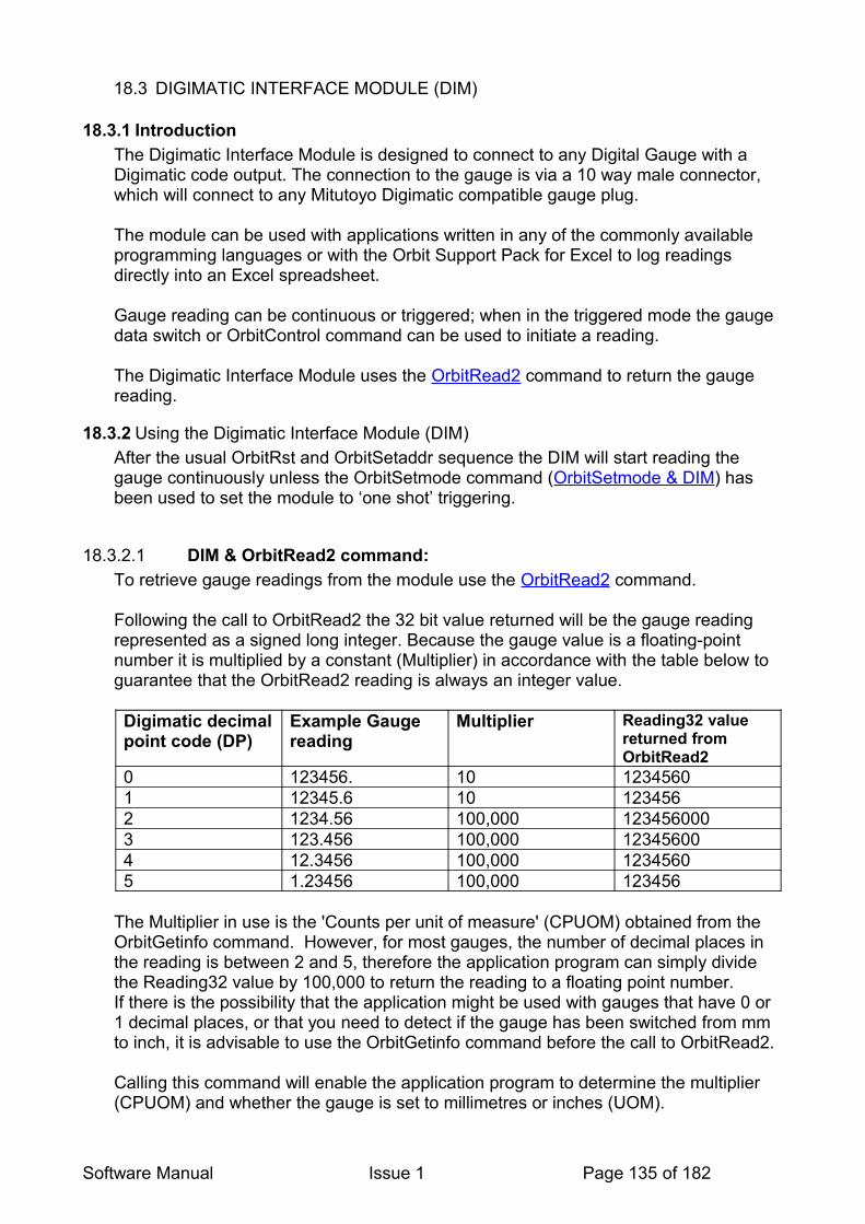
18.3 DIGIMATIC INTERFACE MODULE (DIM)
18.3.1 IntroductionThe Digimatic Interface Module is designed to connect to any Digital Gauge with a Digimatic code output. The connection to the gauge is via a 10 way male connector, which will connect to any Mitutoyo Digimatic compatible gauge plug.
The module can be used with applications written in any of the commonly available programming languages or with the Orbit Support Pack for Excel to log readings directly into an Excel spreadsheet.
Gauge reading can be continuous or triggered; when in the triggered mode the gauge data switch or OrbitControl command can be used to initiate a reading.
The Digimatic Interface Module uses the OrbitRead2 command to return the gauge reading.
18.3.2 Using the Digimatic Interface Module (DIM)After the usual OrbitRst and OrbitSetaddr sequence the DIM will start reading the gauge continuously unless the OrbitSetmode command (OrbitSetmode & DIM) has been used to set the module to ‘one shot’ triggering.
18.3.2.1 DIM & OrbitRead2 command:To retrieve gauge readings from the module use the OrbitRead2 command.
Following the call to OrbitRead2 the 32 bit value returned will be the gauge reading represented as a signed long integer. Because the gauge value is a floating-point number it is multiplied by a constant (Multiplier) in accordance with the table below to guarantee that the OrbitRead2 reading is always an integer value.
Digimatic decimal point code (DP)
Example Gauge reading
Multiplier Reading32 value returned from OrbitRead2
0 123456. 10 12345601 12345.6 10 1234562 1234.56 100,000 1234560003 123.456 100,000 123456004 12.3456 100,000 12345605 1.23456 100,000 123456
The Multiplier in use is the 'Counts per unit of measure' (CPUOM) obtained from the OrbitGetinfo command. However, for most gauges, the number of decimal places in the reading is between 2 and 5, therefore the application program can simply divide the Reading32 value by 100,000 to return the reading to a floating point number.If there is the possibility that the application might be used with gauges that have 0 or 1 decimal places, or that you need to detect if the gauge has been switched from mm to inch, it is advisable to use the OrbitGetinfo command before the call to OrbitRead2.
Calling this command will enable the application program to determine the multiplier (CPUOM) and whether the gauge is set to millimetres or inches (UOM).
Software Manual Issue 1 Page 135 of 182

The gauge reading can now be calculated as follows:
Gauge reading = Reading32 / CPUOM
See Using the Orbitgetinfo Command for more details.
18.3.3 Changing the Mode of OperationWhen in its default state after power up the DIM will attempt to read the gauge continuously, to set the module to ‘one shot’ triggering the OrbitSetmode (OrbitSetmode & DIM) and OrbitControl (OrbitControl & DIM) commands are used as follows.
18.3.4 Reading the DIM statusTo allow the application program to monitor the status word of the module for example to determine if a new reading is ready, or a timeout has occurred, various flags have been assigned in the Orbit status register; these can be read via the OrbitGetstatus command (Digimatic Interface Module (DIM) – Status Format).
18.4 LINEAR ENCODER
18.4.1 Introduction
The Linear Encoder is an incremental, high accuracy measurement module. This module does not support dynamic or buffered modes. Readings are returned via the OrbitRead2 command. The module status word (for example: new reading ready) is returned via the GetStatus command (see Linear Encoder - Status Format).
18.4.2 Linear Encoder & Reference MarkThe OrbitRefmark command is used to obtain the position of the Reference Mark on the Linear Encoder's glass scale. The position information can be used to get absolute reading position in case of a power down or error condition.This eliminates the need to re-master and calibrate your sensor. It is simply required to extend/retract the sensor´s tip which can be done comfortably with pneumatic / motorized linear encoders.The Reference Mark is located approximately 5mm from fully in (retracted).
18.4.2.1 Reference Mark using the Orbit COMThe usage of the reference mark is much easier when using Orbit COM.Simply store the reference mark position in an Offset-Register and subtract this register from any further reading.
The reference mark is being read by using the GetRefMark method shown below:
Moduleobject.GetRefMark
This command returns the Reference Mark position once the mark is passed and needs to be stored into the register.
Software Manual Issue 1 Page 136 of 182

The returned reference mark position needs to be stored into the offset-register. Substract the offset-register value from all further readings returned from ReadCurrent.
After a power down or error, simply read the Reference Mark again and store the returned position in the offset-register.In case of any error (for example: overspeed error) , clear the error (by using the Getstatus method) and read the reference mark again. Once the position has been stored into the offset-register, continue to measure.
Please note:Without using this reference mark sequence, it would always be necessary to remaster or calibrate the sensor after a power-down/error condition.
The reference mark will only be read when moving INWARDS. During outward movement the reference mark will not be read.
18.4.2.2 Reference Mark using the Orbit DLLTo implement the OrbitRefmark command, an offset register is required. This register will store the Reference Mark position and needs to be subtracted from any further readings.
During the initialisation routine , the OrbitRefmark command needs to be send to the module. The PIE module will now wait for the Reference Mark to be passed.When this has been done there will be a flag set which can be read through the OrbitGetstatus command.
Once the flag has been set, the next OrbitRead2 command will return the Reference Mark position.
Note: Another flag in OrbitGetstatus indicates that this reference reading has been read and can be used to avoid misinterpreting the OrbitRead2 value as a normal reading.
The returned Reference Mark position needs to be stored into the offset-register. Substract the offset-register value from all further readings returned from OrbitRead2.
After a power down, simply read the reference mark again and store the returned position in the offset-register.In case of any error (for ex. overspeed error) , clear the error (by using the OrbitGetstatus command) and read the reference mark again. Once the position has been stored into the offset-register, continue to measure.
Software Manual Issue 1 Page 137 of 182
19 ORBIT ERROR CODES AND ERROR HANDLING
19.1 GENERALWhen communicating with the DLL, errors are returned from the DLL function itself.Example: OrbitRead2 command (C format):int OrbitStatus = OrbitRead1 (NetworkNumber, ModuleAddress, &Reading32);//OrbitStatus contains the error code
Errors can be broken down into the following sections:• Module Errors The module has been asked to perform a function that is not allowed orThe module has a fault.• DLL ErrorsThe information passed to the DLL is incorrect or not in the required format.• Orbit Controller ErrorsThe command failed to send from the Orbit Controller.
The following sections list the Error codes and their associated meaning.
19.2 HANDLING ERRORS
Important Note: It is good practice to check for errors after each call to Orbit (DLL/COM)
19.2.1 Error Handling When Using DLL
Each command, when issued, goes:
• Application issues a command to the DLL• If OK, to the Network Controller• If OK, to the Module• Reply To the Network Controller• Reply relayed via the DLL to the application.
Each DLL call returns an error code. The meaning of these individual codes is explained in the following sections.
19.2.2 Error Handling When Using COM
Each command, when issued, goes:
• Application issues a COM function• If OK, to the DLL• If OK, to the Network Controller• If OK, to the Module• Reply To the Network Controller• Reply relayed via the DLL.• Reply relayed via the COM to the application.
Software Manual Issue 1 Page 138 of 182

An error will generate an exception in the COM, which can be handled by the application.
Refer to the Error Handling When Using COM section for more details on error handling with the COM library.
19.3 COMMON ERRORSBelow are listed common error codes. A full list of error codes is shown in the following section.
19.3.1 No ErrorAn error code of 0 implies the command has been successful.
19.3.2 Timeout ErrorAn error code of 0xff (255) implies the command has not been successful – it has ‘timed out’. In other words, an expected reply from the module was not seen and the receiving Orbit Controller ‘timed out’.Under and Over Range
Digital Probe only (0x2112 = UNDER, 0x2113 = OVER)Under and over range are special cases of errors. These are ‘soft’ errors and thus will not cause an exception to be generated if using the COM library. Refer to the COM manual for more details on error handling with the COM library.
19.3.3 Overspeed ErrorLinear Encoder only(0x21C4)This error is returned when the LE has been moved too fast. The readings (incremental) are now suspect and thus should be reset.
The recommended guidelines for dealing with an overspeed error are:
• Wait until the overspeed condition has ceased – otherwise it may be triggered again immediately.
• Send an OrbitGetstatus error – this will reset the LE PIE module.
19.3.4 Address already set(0x000F)If an address has already been allocated, a call to OrbitSetAddr will (at low level) would overwrite the previous module’s assignment. The DLL keeps track of address allocations and will return an error: 0x000f (Address already set) & prevent the change.
Software Manual Issue 1 Page 139 of 182

19.4 ERROR CODES FROM ORBIT MODULES
The table below lists all of the error codes obtained from an Orbit Module. These are returned as a 16 bit code from the DLL. The first (MSB) byte is always 21 hex (‘!’) to indicate that the error emanates from a module.
If a module error occurs, at low (module) level, the acknowledge byte normally sent (e.g. ‘1’ for OrbitRead1) is replaced by a ‘!’ (0x21). The error code is sent on the next byte. Subsequent bytes should be ignored. Note that the number of bytes returned will remain the same, error or not.
Note the 0x prefix implies the number is in hex.
GROUP CODE TYPE DESCRIPTIONGeneral 0x2101 Parity module has received a byte
with a parity error0x2102 Coil Range error with the coil
frequency/parameter. N/A0x2103 No Command module has received an
unrecognized command0x2104 broadcast broadcast address not allowed0x2105 broadcast broadcast address [00]
expected0x2106 Address address change not allowed
(module is set into difference mode)
0x2107 mode cal_mode pin high and cmdR requested or cal_mode pin low and cmd0 requested. N/A
0x2108 calibration table no calibration table in module and cmdR requested.
0x2109 ADC error New ADC cycle started before last cycle completed.
0x210A reading error Reading not yet available, waiting for reading cycle to complete.
0x210B framing error Module received bye with framing error
Algorithm 0x2111 slope error Countx-nearest calibration point>16 bit.
0x2112 range error Countx below min calibration point (underrange)
0x2113 range error Countx above max calibration point (overrrange)
0x2114 maths error multiplication overflowBuffered Mode 0x211A buffer not empty The Orbit Module buffer is not
empty (was error code20h)0x211B buffer empty, probe
stoppedThe orbit module buffer is empty and the probe has stopped collecting data (was error code 21h)
Software Manual Issue 1 Page 140 of 182

Difference Mode 0x2121 Difference Flag not set
0x2122 Diff waiting for trigger to be set
The module has been put into difference mode and is waiting for a trigger command, therefore will respond to other commands like OrbitRead 1 with this error code.
0x2123 Diff mode not allowed, Aquire mode is set
0x2124 diff number overflow >3 bytes
0x2125 diff sum overflow > 5 bytes
0x2126 Diff mode set and running
0x2127 Diff mode not allowed, probe set to high resolution.
Acquire Mode 0x2131 Acquire flag not set NO LONGER SUPPORTED – OLDER PROBES ONLY
Setmode 0x2140 Mode not valid An incorrect mode has been sent to the module either in error or the module cannot respond to that specific mode command.
0x2141 Delay not valid0x2142 Waiting for synch0x2143 Sample running0x2152 capture/sample
mode set 0x2160 Average not valid An illegal average value has
been attempted (-1 DP and New Orbit Modules post 2003 approx.)
0x2161 Average Change not allowed
The module cannot accept a change to the averaging
0x2162 Resolution not valid An illegal resolution value has been attempted (-1 DP and New Orbit Modules post 2003 approx.)
0x2163 Resolution Change not allowed
The module cannot accept a change to the resolution
0x2164 Module set to high resolution
Module in 16 bit or 18 bit mode
0x2165 Module set to low resolution
Module in 14 it mode
0x2166 Not in Normal Mode Module is not in normal mode , module may be in Dynamic mode.
0x2167 address range error (dynamic)
Software Manual Issue 1 Page 141 of 182

0x2168 Module not in high baud rate 1.5 Mbaud
This error would be returned if a module in 187.5kBaud was attempted to be set into dynamic mode
Encoder Module Specific Error codes
0x2170 Input type not valid Mode 70 (Set input type) M_Arg value not valid
0x2171 Quadrature code not valid
Mode 71 (Set quadrature mode) M_Arg value not valid
0x2172 Reference marker Action not valid
Mode 75 (Reference pulse Action) M_Arg value not valid
0x2175 Preset out of range0x2176 OrbitPreset Ignored0x2177 Encoder error EIM has detected change of
state in Error input (Grey wire) Use OrbitGetstatus to clear this condition.
0x2178 Sync gap errorOrbit 5V Power Error Codes
0x2190 Orbit 5V Too Low Warning
0x2191 Orbit 5V Too Low Error.
0x2192 Orbit 5V Too High Error.
0x2194 Orbit 5V High Warning
Hardware Fault Error Codes
0x2193 ADS1252 ADC Fault
Linear Encoder Specific Error Codes
0x21B0 In phase input Low The signal from the LE readhead to the PIE module is too low, probe maybe moving too quickly
0x21B1 In phase Input High0x21B2 Quadrature Input
LowThe signal from the LE readhead to the PIE module is too low, probe maybe moving too quickly
0x21B3 Counter Error Internal Electronics Errors (should not be seen by end users)
0x21B4 DAC Error0x21B8 No ID programmed0x21B9 No Type
programmed0x21BA No Software Version
programmed0x21BB No stroke
programmed0x21BC No calibration Table0x21BD Colon Error0x21BE Checksum Error
Software Manual Issue 1 Page 142 of 182
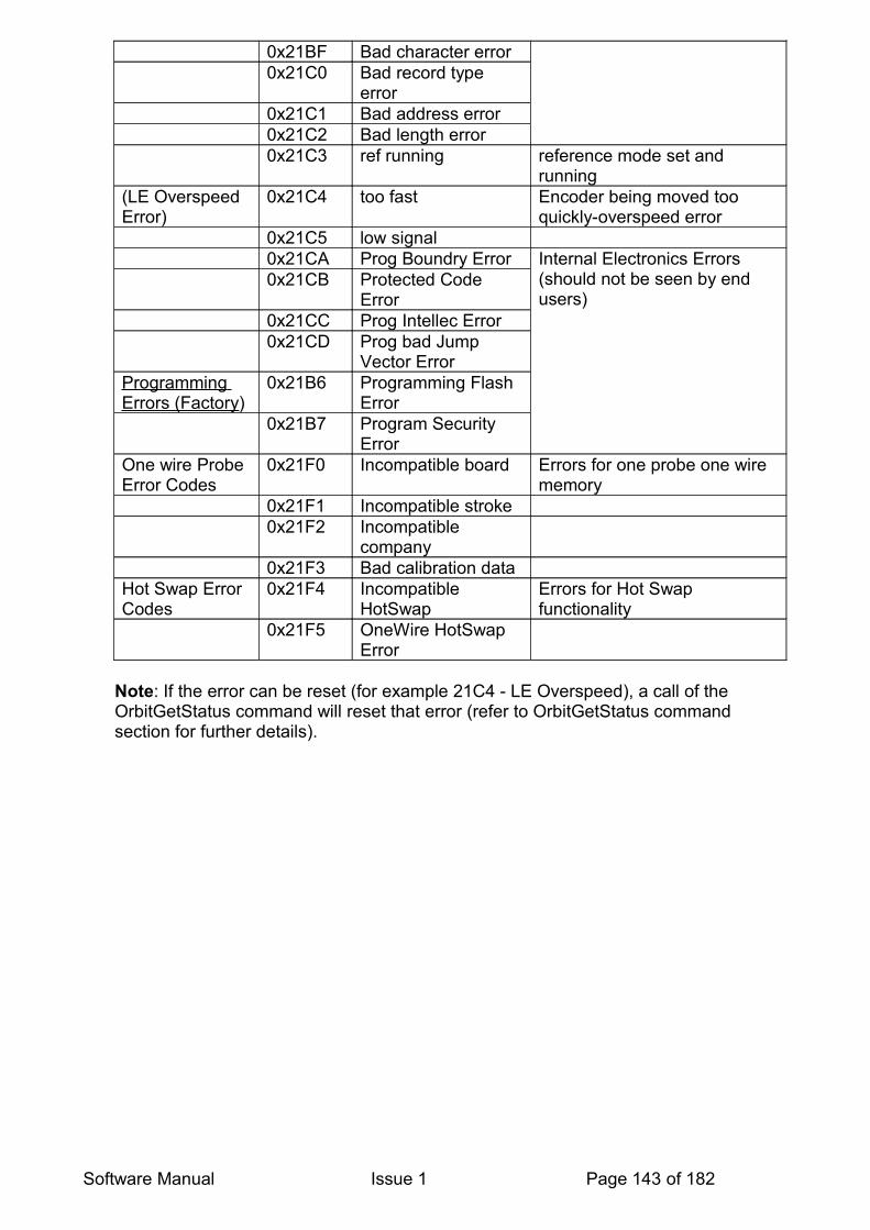
0x21BF Bad character error0x21C0 Bad record type
error0x21C1 Bad address error0x21C2 Bad length error0x21C3 ref running reference mode set and
running(LE Overspeed Error)
0x21C4 too fast Encoder being moved too quickly-overspeed error
0x21C5 low signal0x21CA Prog Boundry Error Internal Electronics Errors
(should not be seen by end users)
0x21CB Protected Code Error
0x21CC Prog Intellec Error0x21CD Prog bad Jump
Vector ErrorProgramming Errors (Factory)
0x21B6 Programming Flash Error
0x21B7 Program Security Error
One wire Probe Error Codes
0x21F0 Incompatible board Errors for one probe one wire memory
0x21F1 Incompatible stroke0x21F2 Incompatible
company0x21F3 Bad calibration data
Hot Swap Error Codes
0x21F4 Incompatible HotSwap
Errors for Hot Swap functionality
0x21F5 OneWire HotSwap Error
Note: If the error can be reset (for example 21C4 - LE Overspeed), a call of the OrbitGetStatus command will reset that error (refer to OrbitGetStatus command section for further details).
Software Manual Issue 1 Page 143 of 182

19.5 DLL ERROR CODES
The list below describes the error codes that occur from the DLL. As these errors are picked up by the DLL, they are not prefixed by the 0x21 (‘!’) byte.
CODE DESCRIPTIONNetwork Controllers 0x0001 Network Controller not found
0x0002 Network Controller Timeout0x0003 Network Controller Write Timeout0x0004 Network Controller Read Timeout0x0005 Not Connected to Orbit Networks0x0006 Unrecognised Network Controller0x0007 Bad RS232 Setting Byte0x0008 Bad Orbit Speed Byte0x0009 Missing Module Acknowledgment
passed parameter errors 0x000A Bad Network Number0x000B Bad Module Address0x000C Bad ID String Length0x000D Bad Module Type String Length0x000E Bad Software Version String Length0x000F Network Address Already Allocated0x0010 Bad Network String Length0x0011 Bad Device Sting Length0x0012 Bad Module Info String Length0x0013 Bad IF Version String Length0x0014 Bad Error String Length
Software Manual Issue 1 Page 144 of 182
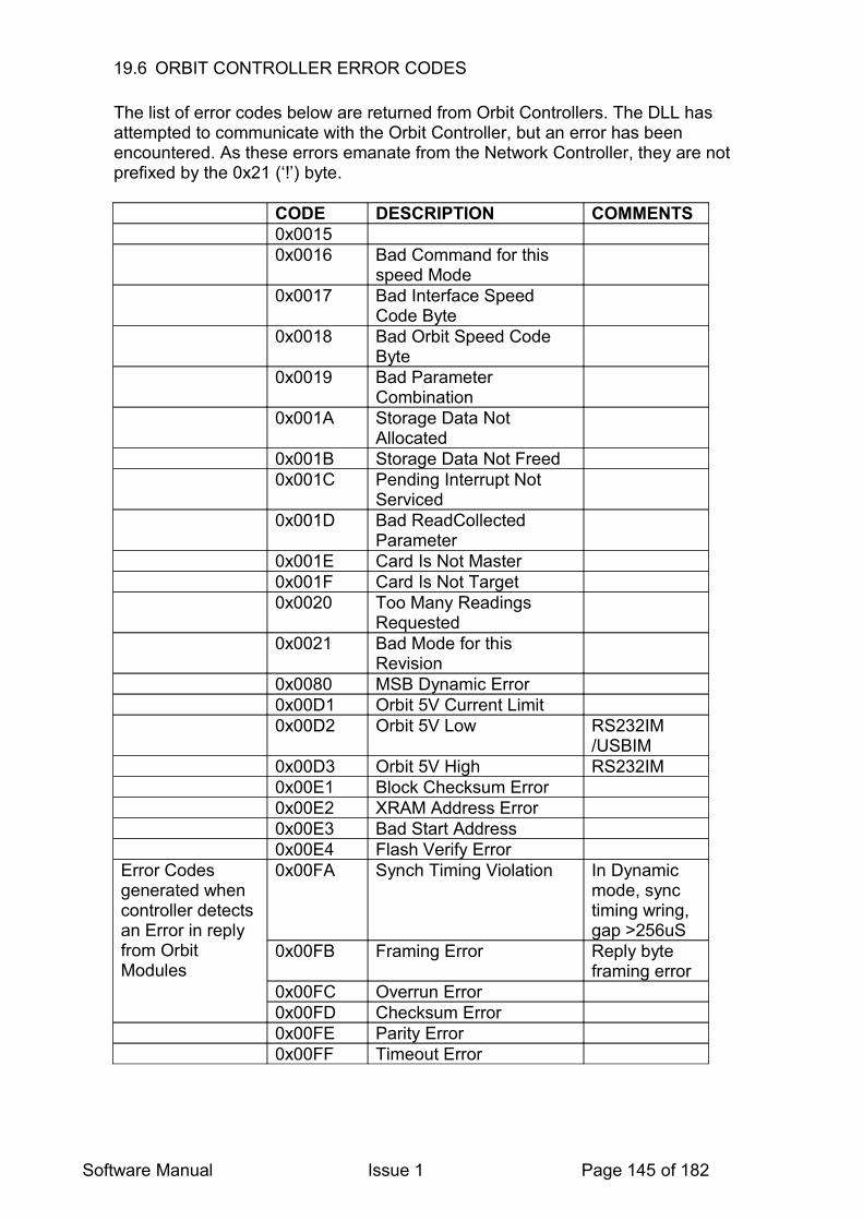
19.6 ORBIT CONTROLLER ERROR CODES
The list of error codes below are returned from Orbit Controllers. The DLL has attempted to communicate with the Orbit Controller, but an error has been encountered. As these errors emanate from the Network Controller, they are not prefixed by the 0x21 (‘!’) byte.
CODE DESCRIPTION COMMENTS0x00150x0016 Bad Command for this
speed Mode0x0017 Bad Interface Speed
Code Byte0x0018 Bad Orbit Speed Code
Byte0x0019 Bad Parameter
Combination0x001A Storage Data Not
Allocated0x001B Storage Data Not Freed0x001C Pending Interrupt Not
Serviced0x001D Bad ReadCollected
Parameter0x001E Card Is Not Master0x001F Card Is Not Target0x0020 Too Many Readings
Requested0x0021 Bad Mode for this
Revision0x0080 MSB Dynamic Error0x00D1 Orbit 5V Current Limit0x00D2 Orbit 5V Low RS232IM
/USBIM0x00D3 Orbit 5V High RS232IM0x00E1 Block Checksum Error0x00E2 XRAM Address Error0x00E3 Bad Start Address0x00E4 Flash Verify Error
Error Codes generated when controller detects an Error in reply from Orbit Modules
0x00FA Synch Timing Violation In Dynamic mode, sync timing wring, gap >256uS
0x00FB Framing Error Reply byte framing error
0x00FC Overrun Error0x00FD Checksum Error0x00FE Parity Error0x00FF Timeout Error
Software Manual Issue 1 Page 145 of 182

Errors in reply from Orbit Module in Dynamic Mode, replaces the 3 byte module output in relevant slot
0x8000FA Dynamic Card Synch Timing Error
0x8000FB Dynamic Module Framing Error
0x8000FC Dynamic Module Overrun Error
0x8000FD Dynamic Module Checksum Error
0x8000FE Dynamic Module Parity Error
0x8000FF Dynamic Module Timeout Error
0x7FFFFFFF
Dynamic Mode Under Range
0xFFFFFFFF
Dynamic Mode Over Range
19.6.1 Specific RS232IM Error CodesFor command types 2, 6 and 8 the RS232IM returns a status byte (byte 1 in String transmitted from RS232IM) to indicate the RS232IM / Orbit status.
Error Code
Error Description
0 Status OK3 RS232Rx receive timeout (RS232Rx command string too short)7 bad RS232Settings byte8 bad Orbit speed byte210 (0D2h) Orbit 5V supply Low211 (0D3h) Orbit 5V supply High253 (0FDh)
Bad checksum - RS232IM calculated checksum not equal to received Orbit module checksum
254 (0FEh) Orbit (RS485) receive parity error255 (0FFh) Orbit (RS485) receive timeout (module reply too short)
Software Manual Issue 1 Page 146 of 182

20 APPLICATION NOTES & EXAMPLES
20.1 COM PROGRAMMING TECHNIQUES AND GUIDELINES
20.1.1 General GuidelinesThis Chapter contains some general suggestions and ideas, which may be useful in the development of software using the Orbit COM library.
Saving and loading Orbit network set-upsIt is possible to save to file the details of the current Orbit network. This file will include the following information:
• Network name • Network type• Communication speed• Number of attached modules• Individual Module ID’s• Module names
It is stored as a standard Windows ini file, an example follows:
[Network]NetName=OrbNetwork1NetType=4ComSpeed=1NumModules=3
[Module0]ModuleID=160SENG306ModuleName=1
[Module1]ModuleID=160SENG303ModuleName=2
[Module2]ModuleID=160SENG304ModuleName=3
Saving the network allows easy re-call of the current network set-up simply by loading in the relevant ini file. This will automatically configure the network with the stored details.
The methods Save( path ) and Load( path ) of the OrbitNetwork object are used to save and load the network set-up ini files respectively with the chosen filename and file path. It is recommended to use both a file load dialog and a file save dialog in conjunction with these methods to make locating the stored ini files easier.
20.1.1.1 Error handlingThe Orbit COM library will generate exceptions as and when needed. If the user does not trap these error conditions, a message box with a description of the problem will be displayed and this will prevent the normal flow of the program. If the user wishes to
Software Manual Issue 1 Page 147 of 182

handle these error conditions, it is recommended to define an exception handling routine that performs any clean up code required, and then displays the generated error message from the Orbit COM library.
20.1.2 Dynamic Collection Guidelines
20.1.2.1 Steps in Performing a Dynamic Collection
1. Add Modules to the Network
2. Prepare the Network for Collection Network Object : PrepareForCollection(NumModules)
3. Start the Collection Server Object : Start Collection(Collection Rate, NumCollectedReadings)
4. Wait for the Networks CollectionMode Property to be CM_DONE ( CM_NONE = 0, CM_ARMED = 1, CM_COLLECTING = 2, CM_DONE = 3 )
5. For each Module in the Network retrieve the collected readings usingModule Object : ReadCollected(ReadingNumber) (0 based)
To perform a new collection repeat steps 2 to 5.
Selecting Networks to be collected on a Network Card
Before Step 3 above you must arm the networks on that card before starting the collection.Valid options are to collect on Channel1 of a card , or on both channels.It is not valid to collect only on Channel 2 as the hardware does not allow this.
20.1.2.2 Steps in Performing a Dynamic Collection with an EIM triggering readings as a master
A minimum of Orbit COM library Version 4.2 is required to use this with an EIM with a Hardware Type of a minimum of 100.
The EIM Must be the last module – so if you have 3 Modules and an EIM the EIM must at Address 4 and the probes 1,2,3.
Due to sharing a bus where only one device can talk at one time care must be taken with the timings there should be a 100ms delay after StartCollection Before Either the Refmark/Preset/Instantaneous Mode causes the EIM to start triggering readings (as such we advise the encoder not be moving during this time).
The readings must not trigger more frequently than every 290µs.
There are 3 Modes that this can be done – Instantaneous, HoldOff or RefMark.
Instantaneous – after StartCollection the EIM starts counting Encoder pulses to trigger a reading straight away.
Software Manual Issue 1 Page 148 of 182

RefMark – After Start Collection the EIM Waits till it has passed its reference mark before it starts counting to trigger pulses.
HoldOff – After StartCollection the EIM starts triggering after the holdoff number of counts have passed
1. Add Modules to the Network2. Set the Network to high speed• If a you wish the device to start instantly then set a preset of 0 on the EIM• If you require a holdoff set the holdoff value.• If you want the readings to trigger off refmark:◦ set RefAction◦ Set Preset
3. Set the TX Sync (number of counts between reads)) value4. Prepare for Collection5. StartCollection6. Sleep for 100ms7. Wait till CollectionMode set to cmDone – during this time ReadLiveData can be
called
20.1.3 Number of modules allowed in Dynamic ModeThe number of modules that can be used on a single network in a dynamic collection varies with the collection rate. The slower the collection rate, the more modules that can be used. The following restrictions apply:
Collection rate Maximum modules
1K 31
2K 16
4K 8
20.1.4 Maximum Number of Readings in a Collection.
The maximum number of Readings that can be taken varies with the Collection Rate as shown in the table below :
Collection rate Maximum No of
Readings
1K 4194303
2K 8338607
4K 16777215
Attempting to use a value greater than these values in StartCollection will result in an error.
Software Manual Issue 1 Page 149 of 182
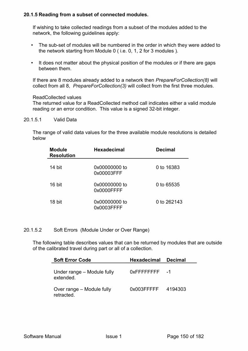
20.1.5 Reading from a subset of connected modules.
If wishing to take collected readings from a subset of the modules added to the network, the following guidelines apply:
• The sub-set of modules will be numbered in the order in which they were added to the network starting from Module 0 ( i.e. 0, 1, 2 for 3 modules ).
• It does not matter about the physical position of the modules or if there are gaps between them.
If there are 8 modules already added to a network then PrepareForCollection(8) will collect from all 8, PrepareForCollection(3) will collect from the first three modules.
ReadCollected valuesThe returned value for a ReadCollected method call indicates either a valid module reading or an error condition. This value is a signed 32-bit integer.
20.1.5.1 Valid Data
The range of valid data values for the three available module resolutions is detailed below
Module Resolution
Hexadecimal Decimal
14 bit 0x00000000 to 0x00003FFF
0 to 16383
16 bit 0x00000000 to 0x0000FFFF
0 to 65535
18 bit 0x00000000 to 0x0003FFFF
0 to 262143
20.1.5.2 Soft Errors (Module Under or Over Range)
The following table describes values that can be returned by modules that are outside of the calibrated travel during part or all of a collection.
Soft Error Code Hexadecimal Decimal
Under range – Module fully extended.
0xFFFFFFFF -1
Over range – Module fully retracted.
0x003FFFFF 4194303
Software Manual Issue 1 Page 150 of 182

20.1.5.3 Fatal Errors
The following table describes fatal error codes that can be returned by modules during a collection.
Probe Collection Errors Hexadecimal Decimal
Framing error 0x008000FB 8388859
Overrun error 0x008000FC 8388860
Checksum error 0x008000FD 8388861
Parity error 0x008000FE 8388862
Timeout 0x008000FF 8388863
If any of these fatal error codes are encountered, the collection will terminate, and any values reserved for readings not yet taken will be set to:
Condition Hexadecimal Decimal
Empty – No reading from module.
0x00400000 4194304
Software Manual Issue 1 Page 151 of 182

20.1.6 Use of ReadLiveData method
To enable readings to be sampled during a collection a Method is providedat Network Object level called ReadLiveData.
This returns a variant array of 64 Integers which represent the Module Reading values for both channels of a Network Card. (Up to 16 Modules @ 4k, 32 @ 2k or 62 @ 1k)This is an asynchronous call and will just give the last data collected for that network card. However this is useful for monitoring values during a finite collection.
The collected values will not be affected by using this call, it just obtains a ‘snapshot’of the most recent collected data for a particular network card.
This call is best used during the loop in step 4 above, while waiting for the Networks CollectionMode property to change from CM_COLLECTING to CM_DONE
The array size is always 64 for all collection Rates , but all elements may not befilled, depending on Data Rate and Number of Modules used in the collection.Unused elements are set to the ‘Empty Reading’ value 00400000 in Hex
DataMaps for each Rate are shown below
Array element 63 now contains an integer showing the reading number of the dynamic collection that was sampled.
Software Manual Issue 1 Page 152 of 182
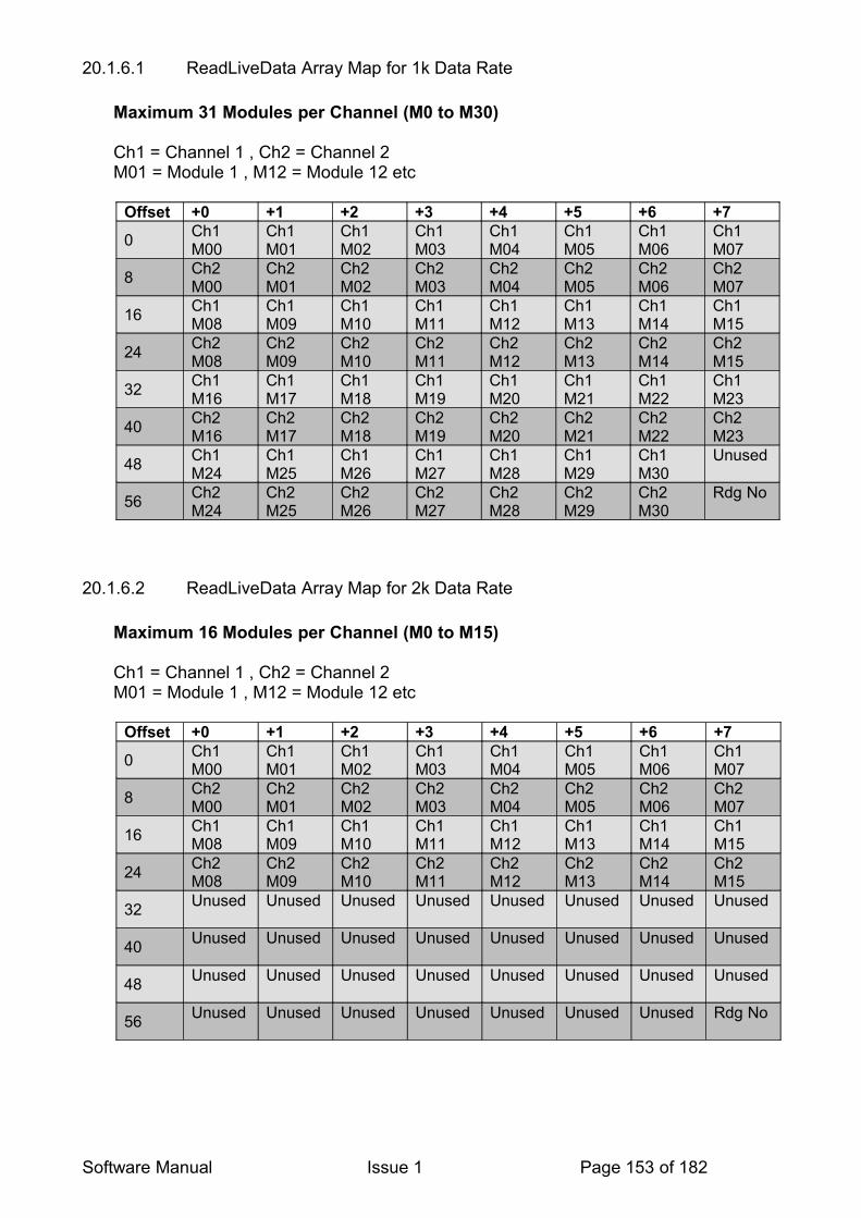
20.1.6.1 ReadLiveData Array Map for 1k Data Rate
Maximum 31 Modules per Channel (M0 to M30)
Ch1 = Channel 1 , Ch2 = Channel 2M01 = Module 1 , M12 = Module 12 etc
Offset +0 +1 +2 +3 +4 +5 +6 +7
0 Ch1M00
Ch1M01
Ch1M02
Ch1M03
Ch1 M04
Ch1 M05
Ch1 M06
Ch1 M07
8 Ch2 M00
Ch2 M01
Ch2 M02
Ch2 M03
Ch2 M04
Ch2 M05
Ch2 M06
Ch2 M07
16 Ch1M08
Ch1M09
Ch1M10
Ch1M11
Ch1 M12
Ch1 M13
Ch1 M14
Ch1 M15
24 Ch2 M08
Ch2 M09
Ch2 M10
Ch2 M11
Ch2 M12
Ch2 M13
Ch2 M14
Ch2 M15
32 Ch1M16
Ch1M17
Ch1M18
Ch1M19
Ch1 M20
Ch1 M21
Ch1 M22
Ch1 M23
40 Ch2 M16
Ch2 M17
Ch2 M18
Ch2 M19
Ch2 M20
Ch2 M21
Ch2 M22
Ch2 M23
48 Ch1M24
Ch1M25
Ch1M26
Ch1M27
Ch1 M28
Ch1 M29
Ch1 M30
Unused
56 Ch2 M24
Ch2 M25
Ch2 M26
Ch2 M27
Ch2 M28
Ch2 M29
Ch2 M30
Rdg No
20.1.6.2 ReadLiveData Array Map for 2k Data Rate
Maximum 16 Modules per Channel (M0 to M15)
Ch1 = Channel 1 , Ch2 = Channel 2M01 = Module 1 , M12 = Module 12 etc
Offset +0 +1 +2 +3 +4 +5 +6 +7
0 Ch1M00
Ch1M01
Ch1M02
Ch1M03
Ch1 M04
Ch1 M05
Ch1 M06
Ch1 M07
8 Ch2 M00
Ch2 M01
Ch2 M02
Ch2 M03
Ch2 M04
Ch2 M05
Ch2 M06
Ch2 M07
16 Ch1M08
Ch1M09
Ch1M10
Ch1M11
Ch1 M12
Ch1 M13
Ch1 M14
Ch1 M15
24 Ch2 M08
Ch2 M09
Ch2 M10
Ch2 M11
Ch2 M12
Ch2 M13
Ch2 M14
Ch2 M15
32 Unused Unused Unused Unused Unused Unused Unused Unused
40 Unused Unused Unused Unused Unused Unused Unused Unused
48 Unused Unused Unused Unused Unused Unused Unused Unused
56 Unused Unused Unused Unused Unused Unused Unused Rdg No
Software Manual Issue 1 Page 153 of 182
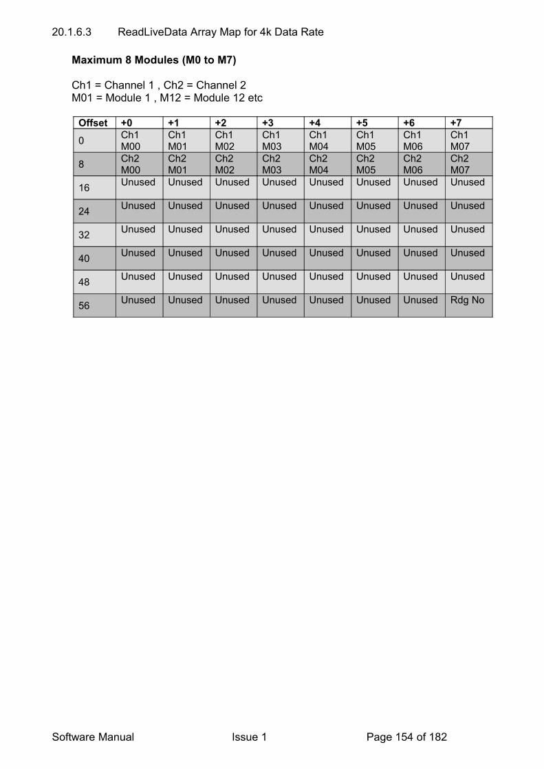
20.1.6.3 ReadLiveData Array Map for 4k Data Rate
Maximum 8 Modules (M0 to M7)
Ch1 = Channel 1 , Ch2 = Channel 2M01 = Module 1 , M12 = Module 12 etc
Offset +0 +1 +2 +3 +4 +5 +6 +7
0 Ch1M00
Ch1M01
Ch1M02
Ch1M03
Ch1 M04
Ch1 M05
Ch1 M06
Ch1 M07
8 Ch2 M00
Ch2 M01
Ch2 M02
Ch2 M03
Ch2 M04
Ch2 M05
Ch2 M06
Ch2 M07
16 Unused Unused Unused Unused Unused Unused Unused Unused
24 Unused Unused Unused Unused Unused Unused Unused Unused
32 Unused Unused Unused Unused Unused Unused Unused Unused
40 Unused Unused Unused Unused Unused Unused Unused Unused
48 Unused Unused Unused Unused Unused Unused Unused Unused
56 Unused Unused Unused Unused Unused Unused Unused Rdg No
Software Manual Issue 1 Page 154 of 182

20.2 READING AN ORBIT MODULEIn order to read from an Orbit module using the COM, simply call the ReadCurrentInUOM method to get the readings in the units of measure. Alternatively you can call the ReadCurrent method to get the reading as a scaled integer (from 0 to the module resolution),however you will need to do the calculations yourself.
If you need to read from an Orbit module not using the COM, it is first necessary to get information about that module. • Use OrbitIdentify to return the stroke.
• Use OrbitGetinfo to return the moduleinfo & scale.
• Look at RTS from the moduleinfo string (Refer to Converting Readings to Units Of Measure (UOM) section)
• Values: 0 = Read1 and Read2, 1 = Read 1 only ,2 = Read2 only
• Call OrbitRead1 or OrbitRead2 as appropriate.
• Tip: DP, LE, EIM, AIM modules all support OrbitRead2 commands. Use OrbitRead2 command by default.
• Use the COM or “Method to use Moduleinfo for all module Types” section to work out the reading. Use the examples in this section to aid this calculation.
Note: Because of the RANGE flag you can only ever read up to one bit less than the stroke (before you hit OVER and UNDER range) this means the probe never quite has the range of the stroke.
Software Manual Issue 1 Page 155 of 182

20.3 DIGIMATIC INTERFACE MODULE (DIM) CODE EXAMPLESThe examples below are written in C format and describe how to read a DIM in its three different operating modes.
20.3.1 Taking a Gauge reading continuously
NetworkNumber = 0;ModuleAddress = 1;Mode = 90;M_Arg = 0;
OrbitStatus = OrbitSetmode(NetworkNumber,ModuleAddress,&Mode,&M_Arg); // see note 1
do{
do{
// see note 2OrbitStatus =
OrbitGetstatus(NetworkNumber,ModuleAddress,&errcode,&status); }while ((status & 0x800) == 0 && (status & 1) == 0);
if((status & 1) == 1) {
printf(“Timeout \n”); } else {
// get reading and print OrbitStatus = OrbitRead2(NetworkNumber,ModuleAddress,&Reading32); Reading = (double) Reading32 / 100000; // see note 3 printf(“Reading32 = %d, Gauge Reading = %4.4f \n”, Reading32, Reading);
}}while(OrbitStatus == 0 && !kbhit());
Note 1 - This line is setting the DIM to mode 0 is only required if modes 1 or 2 have previously been set, the default at ‘power on’ or after an OrbitRst is mode 0 (continuous).
Note 2 - Calling OrbitGetstatus is only required if you wish to check for a ‘New’ reading from the gauge or to check for a gauge communication timeout.
Note 3 - OrbitGetstatus can be used to get the divisor value (CPUOM) if required, in this example we use the constant (100,000) which will be satisfactory for applications where the gauge used has a resolution of between 2 and 5 decimal places.
Software Manual Issue 1 Page 156 of 182
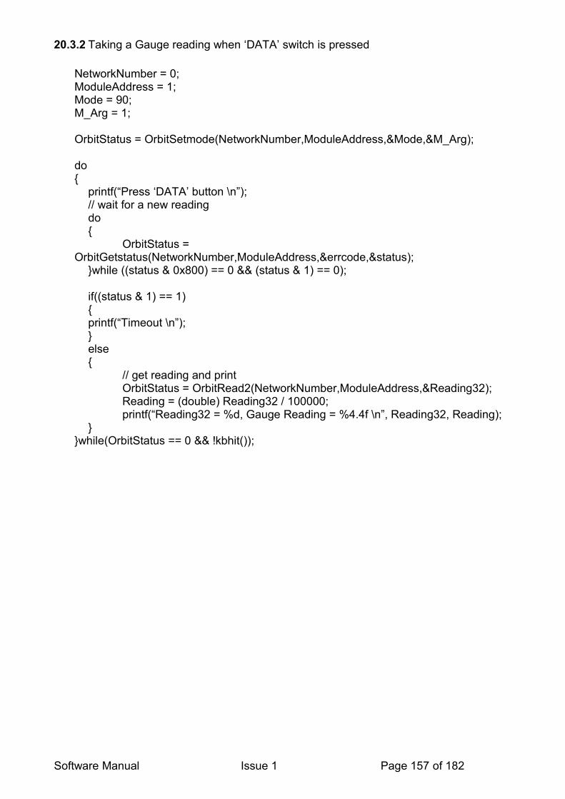
20.3.2 Taking a Gauge reading when ‘DATA’ switch is pressed
NetworkNumber = 0;ModuleAddress = 1;Mode = 90;M_Arg = 1;
OrbitStatus = OrbitSetmode(NetworkNumber,ModuleAddress,&Mode,&M_Arg);
do{
printf(“Press ‘DATA’ button \n”); // wait for a new reading do {
OrbitStatus = OrbitGetstatus(NetworkNumber,ModuleAddress,&errcode,&status);
}while ((status & 0x800) == 0 && (status & 1) == 0);
if((status & 1) == 1) { printf(“Timeout \n”); } else {
// get reading and print OrbitStatus = OrbitRead2(NetworkNumber,ModuleAddress,&Reading32); Reading = (double) Reading32 / 100000; printf(“Reading32 = %d, Gauge Reading = %4.4f \n”, Reading32, Reading);
}}while(OrbitStatus == 0 && !kbhit());
Software Manual Issue 1 Page 157 of 182

20.3.3 Taking a Gauge reading when Key is pressed (using OrbitControl (Action=30))
NetworkNumber = 0;ModuleAddress = 1;Mode = 90;M_Arg = 2;
OrbitStatus = OrbitSetmode(NetworkNumber,ModuleAddress,&Mode,&M_Arg);
do{
// wait for operator to press key printf(“Press any key to take reading \n”); do { }while(!kbhit());
Action = 30; OrbitStatus = OrbitControl(NetworkNumber,&Action); // wait for new reading do {
OrbitStatus = OrbitGetstatus(NetworkNumber,ModuleAddress,&errcode,&status);
}while ((status & 0x800) == 0 && (status & 1) == 0);
if((status & 1) == 1) {
printf(“Timeout \n”); } else {
// get reading and print OrbitStatus = OrbitRead2(NetworkNumber,ModuleAddress,&Reading32); Reading = (double) Reading32 / 100000; printf(“Reading32 = %d, Gauge Reading = %4.4f \n”, Reading32, Reading);
} int c = getch();
}while(OrbitStatus == 0 && !kbhit());
Software Manual Issue 1 Page 158 of 182

20.4 DIOM EXAMPLEIn the example below, Port 1 (bit 1) is driving a load and Port 0 (bit 0) is an input to a switch. No other port is used in this example.All example input states are read back correctly except the last, where Port 1 (bit 1) output driver is switched ON, causing a false input state to be read by the Port 1 inputbuffer.Note. This last condition is an example of the DIOM monitoring its own output state
Remember: Input and output ports are internally connected.Therefore, for each I/O line, the output driver must be OFF (bit=1) before it can be used as an input.
20.4.1 Multiple ReadingsIn some applications, multiple readings of OrbitRead1 maybe required, i.e:• External electrical interference• Switch bounce• Noisy supplies• Mechanical vibrationIf a port is being used to read a switch condition forexample, a single OrbitRead1 may have missed the event ormay have seen a noise spike in the place of the event.A possible solution is to issue multiple OrbitRead1commands to confirm the input status.
Software Manual Issue 1 Page 159 of 182
20.5 USING THE ORBITGETINFO COMMAND
It is highly recommended that the Orbit COM library is used for accessing the OrbitGetinfo command.The COM library provides a ReadCurrentInUOM method along with other properties so the user does not need to access the low level OrbitGetinfo commandThis is a very complex command and the Orbit COM library has been structured to simplify its use.
If you really need to access it at the low level, the method is described below.
A call to the OrbitGetinfo command returns 4 parameters these are:
Module Type (4 character string)Hardware Type (integer)Scale (integer)Module Information (32 character string)
They are described in detail in the subsequent paragraphs
20.5.1 Module Type
This parameter shows the generic type of the module. It does not change for customer specials. The details are shown in the table below.
Character No1 2 3 4 DescriptionD P Digital probeD A Analogue input moduleD D Gauging / displacement etc.D L Digital Lever probeD M Digital Mini ProbeD K Digital block gaugeD E Encoder input moduleL E Linear EncoderD I O M Digital I/O module M D M Motor Drive Module (see note 1)D H LE & EIM combination (LEIM)D U Digital FlexureD I M Digimatic Interface Module
Note 1. MDM will have ModuleInfo = 32 spacesThis is a legacy product, used with the LE50M & LE100M products.
Note2: The ‘DeviceType’, which is returned from the OrbitIdentify command, is different to the ModuleType. DeviceType can be modified to suit customer needs if required (example DeviceType -JPN10)
Software Manual Issue 1 Page 160 of 182

20.5.2 Hardware Type
This parameter shows the Hardware Type of the module. Until 2006, this command was used internally to distinguish between different hardware e.g. LE, DP, AIM etc. and different builds of the same hardware e.g. standard v buffered.It is no longer maintained, but is listed for backward compatibility only.
Value Description1 LE (and MDM in error)2 Classic DP – Buffered3 Jupiter Issue 1 (PCB 104126)4 Jupiter Issue 2 (PCB 104126)5 Jupiter Issue (3 & 4 PCB 104126)6 Reserved – intended for buffered 1041267 Jupiter Issue 2 – 4 (PCB 104266) dynamic8 Jupiter Issue 2 – 4 (PCB 104266) dynamic & buffered9 Analogue Input Module Issue 1 & 2 (PCB 104416) (AIM)10 Reserved for buffered 10441611 Encoder Input Module Issue 1 & 2 (PCB 104426)12 Reserved for buffered 10442613 AIM – Bridge Version (104706)14 Digimatic Interface Module (104606)15 Jupiter Issue 1 ext. memory option (104726)16 Probe only – external memory option100 P300 DP_AIM, EIM, DIOM, DIM – metal PIE case150 ORBIT3 DP_AIM, EIM, DIOM, DIM – plastic PIE case
20.5.3 Scale (formerly known as Resolution)
This parameter (formerly known as Resolution) is used to store information relating to the physical measurement.
Value Description (used with)0 DP / DD / Digital Flexure & Block Gauge with strokes >= 1mm 1 Encoder input module – EIM, Digimatic Interface Module5 Linear Encoder – LE (represents 50nm)16 Analogue input module – AIM (4-20mA)20 LEIM (represents 200nm)500 Digital probe (0.5mm), Digital Mini Probe, Digital Lever probe5000 Analogue input module – AIM (0-5V)20000 Analogue input module – AIM (0-20V or –10V to +10V)
Note 1. If the Stroke returned from the OrbitIdentify command is 0 then the measuring range of the module is held in the Scale parameter.
Software Manual Issue 1 Page 161 of 182
20.5.4 ModuleInfo
Please note that in the following text ‘Classic ’ modules are defined as LE , non-Jupiter DP, The ModuleInfo string is split into different fields as shown below.
Compatibility
ModuleInfo Character 1
1 Module typeClassic module - blank
D Dynamic (plus high speed)H High speed (1.5MBaud)
Unit of measure (UOM)
ModuleInfo Characters 2 – 7
DR units uses the first 4 characters to go above one of the buttons. Text is centered to suit DR.UOM can also be used by an application if required.
2 3 4 5 6 7 Module typeClassic module - blank
m m Digital Probes, Gauging / displacement, DIM etc.
m A AIM (mA)V AIM (V)
EIM / DIMD e g C AIM (Temperature)
g AIM (load cell)i n c h DIM set to inches
Counts per unit of measure (CPUOM)
ModuleInfo Characters 8 – 15
Floating point numberexpressed as string(e.g. “1.2345”)
CPUOM is the value when the module is at its default resolution
8 9 10 11 12 13 14 15 Module typeClassic module – all blank
0 0 0 2 0 0 0 0 LE120 0 0 2 0 0 0 0 LE250 0 0 2 0 0 0 0 LE500 0 0 2 0 0 0 0 LE1000 0 0 3 2 7 6 8 DP05, DM05, DL050 0 0 1 6 3 8 4 DP10 0 0 0 8 1 9 2 DP20 0 3 2 7 6 . 8 DP50 0 1 6 3 8 . 4 DP100 0 0 8 1 9 . 2 DP205 4 . 6 1 3 3 3 DD3000 0 0 1 6 3 8 4 1V AIM0 0 3 2 7 6 . 8 5V AIM0 0 1 6 3 8 . 4 10V AIM0 0 0 0 1 0 2 4 4 – 20 mA AIM0 0 0 0 8 1 9 2 +/- 1V AIM0 0 1 6 3 8 . 4 +/- 5V AIM0 0 0 8 1 9 . 2 +/- 10V AIM0 0 0 4 0 9 . 6 +/- 20 mA AIM0 0 0 0 0 0 0 1 EIM0 0 0 0 0 0 0 1 DIOM0 0 0 2 0 . 4 8 Temp 0 to 8000 0 0 0 0 0 1 6 Temp –24 to +10000 0 0 0 5 0 0 0 LEIM (x200)
Software Manual Issue 1 Page 162 of 182

0 0 0 0 0 0 5 0 EIM 20um scale (LUK GmbH)
0 0 0 0 0 0 1 0 DIM - DP code 0 or 10 0 1 0 0 0 0 0 DIM - DP code 2 to 5
Offset (OS)
ModuleInfo Characters 16 – 21
Floating point number expressed as string e.g. “+32.1”
16 17 18 19 20 21 Module typeClassic module - blank
+ 0 0 0 0 0 DP, LE, EIM, DIOM, LEIM, DM, DL, DK, DU, Unipolar AIM, DIM
- 0 0 0 0 1 + / - 1V AIM- 0 0 0 0 5 + / - 5V AIM- 0 0 0 1 0 + / - 10V AIM- 0 0 0 2 0 + / - 20mA AIM+ 0 0 0 0 4 4 – 20 mA AIM- 0 0 0 2 4 Temp –24 to +1000
No of chars before decimal point (NCBDP)
ModuleInfo character 22 Mainly used by DRO etc. to position the decimal point on the display, Range “0” to “9”
22 Module typeClassic module – blank
3 DP, LE, DD, AIM, LEIM, DM, DL, DK, DU(EIM for LUK GmbH), DIM
6 EIM, DIOM, AIM (temp)
Explanation: DRO 10 character display layout
No of chars before decimal point = 3
(-) X X X ▪ X X X X X X
No of chars before decimal point = 6
(-) X X X X X X ▪ X X X
Read types supported (RTS)
ModuleInfo character 23Used by DRO etc. to check the module read capabilities, Range “0” to “9”
23 Module typeClassic module - blank
0 DP, AIM, DM, DL, DK, DU1 DIOM2 LE, EIM, LEIM, DIM
0 = OrbitRead1 and OrbitRead21 = OrbitRead1 only2 = OrbitRead2 only
Characters 24 – 30 = Spaces (reserved for future expansion)Multiplier (MULT)ModuleInfo characters 31 - 32 Range “00” to “99”
31 32Classic module - blank
0 1 module set to default resolution (14bits), EIM / LEIM Quad x1 mode
0 2 EIM / LEIM Quad x2 mode0 4 module set to 4x default resolution (16 bits), &
EIM / LEIM Quad x41 6 module set to 16x default resolution (18 bits)
Software Manual Issue 1 Page 163 of 182

For Jupiter modules “01” = 14bit, “04” = 16bit, “16” = 18bit.
For Digital Probe Jupiter products the Module initialises MULT at power up to the default resolution (14bits), this can be changes with the OrbitSetmode command
MULT will be “01” for the remaining types of measurement modules (LE, EIM and DIOM)The default MULT value blown into code at calibration must be “01” (the value “ 1”, used previously, has been superseded)
Notes: Where there is a blank character position, the ASCII character is SPACE (0x20 Hex, 32 decimal)Classic modules are: Classic DP, LE, DIOM, MDM.These Modules all contain 32 spaces.A Classic non buffered DP does not support OrbitGetinfo, a call to this function will return status=0xFF (timeout). Software can use this response as confirmation of module type = “DP “
20.5.5 Converting Readings to Units Of Measure (UOM)
The Moduleinfo is used to calculate the reading in the correct units. The prefered way of interrogating the ModuleInfo string is to use the COM object ReadCurrentInUOM. However, if the user wants to implement their own algorithm using the supplied DLL, the reading can be calculated from the equation below and using the ModuleInfo conversion methods detailed in the following sections.
Reading in UOM = (N/(CPUOM * MULT)) + OS
Where
N = number returned from OrbitRead1 or OrbitRead2UOM = units of measureMULT = multiplier which will be1, 4 or 16 depending on how the module resolution has been set, i.e. 14 bit, 16 bit or 18 bit.CPUOM = counts per unit of measureOS = offset in units of measure
20.5.5.1 UOM example - Digital Probe set to 16 bit mode.
From the tables under the previous paragraphMULT=4, CPUOM=1638., OS = 0, UOM = “mm”
Therefore Reading in UOM = (N/(CPUOM * MULT)) + OS
And so Reading (mm) = (N/(1638.4 * 4) + 0
For a Digital Probe set to 16 bit mode N will range from 0 to 2^16 (65536)
Examples are as below
Software Manual Issue 1 Page 164 of 182
N Equation Reading (mm) Note1 Reading = 1/(1638.4*4)+0 0.00015 Resolution10 Reading = 10/(1638.4*4)+0 0.00152000 Reading = 2000/(1638.4*4)+0 0.30532768 Reading = 32768/(1638.4*4)+0 5 Mid Range
20.5.5.2 UOM example - Analogue Input Module 4-20mA 18bit mode
From the tables under the previous paragraphMULT=16, CPUOM=1024., OS = 4, UOM = “mA”
For an AIM set to 18 bit mode N will range from 0 to 2^18 (262144)
N Equation Reading (mA) Note0 Reading = 0/(1024*16)+4 4 Minimum131072 Reading = 131072/(1024*16)+4 16 Mid Range262144 Reading = 262144/(1024*16)+4 20 Full Range
20.5.5.3 UOM example - Analogue Input Module +/-10V 14bit mode
From the tables under the previous paragraphMULT=1, CPUOM=819.2, OS = -10, UOM = “mA”
For an AIM set to 14 bit mode N will range from 0 to 2^14 (16384)
N Equation Reading (mA) Note0 Reading = 0/(819.2*16)-10 -10 Minimum8192 Reading = 8192/(819.2*16)-10 0 Mid Range16348 Reading = 16348/(819.2*16)-10 +10 Full Range
20.5.6 Method to use Moduleinfo for all module Types
The following flow chart describes a general-purpose method that can used to enable any future Orbit software to correctly calculate a result, representing the Module Output Value in it's native Units of Measurement. (I.e. 2.1043 V). It caters for newer Modules with a fully completed ModuleInfo string and also earlier Modules by examining other Module data.Providing future Modules have correct ModuleInfo information, the programs should not require modification to cope with future module types. The process modifies a generic set of data values described below
DATA VARIABLES USED BY THIS PROCESS
Compatibility Type : CharValue 'D' = Dynamic plus Hi Speed 'H' = Hi Speed (Not used at present) ' ' = Classic
Software Manual Issue 1 Page 165 of 182
UOM:Type : 6 character String describing Unit of Measurement
CPUOMType : Floating Point Value representing Counts per Unit of Measure
OSType : Floating Point Value representing Offset in Units of Measure NCBDPType : Integer (Used by DRO Only)
RTSType : Integer showing Read Types SupportedValues: 0 = Read1 and Read21 = Read 1 only 2 = Read2 only
MULTType: Integer used to scale result when Module Resolution is changedValues : 1 , 4, 16 (0 to 99 legal range)
The program can now represent the Reading in Units of Measure by using the equation below. N represents the integer value returned from a OrbitRead1 or OrbitRead2 command.
Reading = ( N / ( CPUOM * MULT)) + OS
The UOM String can be used to show the units of measurement .
Using Moduleinfo - FlowchartThe following flowchart can be used to determine the method required to read a module. Note that specific part numbers are listed here that cover certain modules and how to read them. Note also that the module info string was not implemented in classic modules or early Jupiter Digital Probes. This complicates the method somewhat.
Software Manual Issue 1 Page 166 of 182

Software Manual Issue 1 Page 167 of 182
Convert the last two characters ofModuleInfo to an integer.
Is the result > 0 ?
Module does notuse full
ModuleInfoformat
Module uses fullModuleInfo
format
OLD FORMATGo to
OF
NEW FORMATGo to
NF
Use Orbit Identify toobtain DeviceType
and Stroke
Use Orbit GetInfo
Did GetInfo Respond ?
ModuleType, HWType, Scale andModuleInfo
will have been set by call to GetInfo
Yes
Set ModuleType = "DP "Compatibility = ' '
No
Is First Character ofModuleInfo = 'D' ?
Compatibility =' '
Compatibility ='D'
YesNo
No Yes

Software Manual Issue 1 Page 168 of 182
From NF
NEW FORMAT
Extract Data from ModuleInfo String and put into variables
( See Data Module on Page 1)
Compatibility = ModuleInfo String Character 1
UOM = String copied from Characters 2 to 7
CPUOM = Float value of Characters 8 to 15
OS = Float Value of Characters 16 to 21
NCBDP = Integer value of Character 22
RTS = Integer value of Character 23
MULT = Integer value of Characters 31 to 32
End of Process for NEW FORMAT
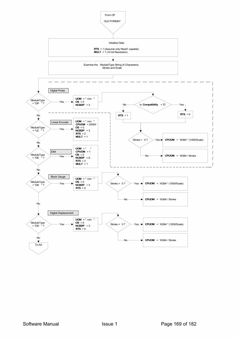
Software Manual Issue 1 Page 169 of 182
From OF
OLD FORMAT
Initialise Data
RTS = 1 (Assume only Read1 capable)MULT = 1 (14 bit Resolution)
Examine the ModuleType String (4 Characters)Stroke and Scale
ModuleType= "DP " ?
UOM = " mm " OS = 0 NCBDP = 3
Yes
Stroke = 0 ? CPUOM = 16384 * (1000/Scale)Yes
CPUOM = 16384 / StrokeNo
ModuleType= "LE " ?
No
UOM = " mm "CPUOM = 20000
OS = 0 NCBDP = 3
RTS = 2MULT = 1
Yes
ModuleType= "DE " ?
UOM = " "CPUOM = 1
OS = 0 NCBDP = 6
RTS = 2MULT = 1
Yes
No
ModuleType= "DK " ?
UOM = " mm " OS = 0 NCBDP = 3
RTS = 0
Stroke = 0 ? CPUOM = 16384 * (1000/Scale)Yes
CPUOM = 16384 / StrokeNo
No
Yes
ModuleType= "DD " ?
UOM = " mm " OS = 0 NCBDP = 3
RTS = 0
Stroke = 0 ? CPUOM = 16384 * (1000/Scale)Yes
CPUOM = 16384 / StrokeNo
Yes
No
To AA
No
Digital Probe
Linear Encoder
EIM
Block Gauge
Digital Displacement
Is Compatibilty = 'D'
RTS = 1 RTS = 0
No Yes

Software Manual Issue 1 Page 170 of 182
FromAA
ModuleType= "DM " ?
UOM = " mm " OS = 0 NCBDP = 3
Stroke = 0 ? CPUOM = 16384 *(1000/Scale)
Yes
CPUOM = 16384 / StrokeNo
Yes
ModuleType= "DL " ?
UOM = " mm " OS = 0 NCBDP = 3
Stroke = 0 ? CPUOM = 16384 *(1000/Scale)
Yes
CPUOM = 16384 / StrokeNo
Yes
No
UOM = " "CPUOM = 1
OS = 0 NCBDP = 6RTS = 1MULT = 1
ModuleType= "DIOM " ?
No
Mini Probe
Lever Probe
Yes
DIOM
ToAB
No
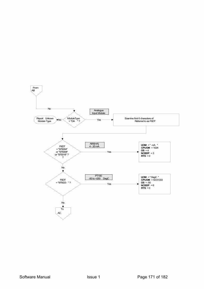
Software Manual Issue 1 Page 171 of 182
FromAB
ModuleType= "DA " ?
NoAnalogue
Input Module
Report UnkownModule Type No Examine first 6 characters of
DevType Referred to as F6DTYes
F6DT= "975004"or "975008"
or "975018" ? ?
UOM = " mA "CPUOM = 1024
OS = 4 NCBDP = 3
RTS = 0
Yes
F6DT= "975023 " ?
UOM = "DegC "CPUOM = 54.61333
OS = -50 NCBDP = 6
RTS = 0
Yes
No
AIM(mA)4 - 20 mA
PT100-50 to +250 DegC
To
AC
No
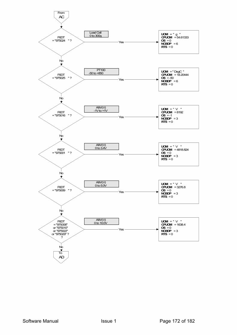
Software Manual Issue 1 Page 172 of 182
FromAC
F6DT= "975024 " ?
UOM = " g "CPUOM = 54.61333
OS = 0 NCBDP = 6RTS = 0
Yes
Load Cell0 to 300g
F6DT= "975025 " ?
UOM = " DegC "CPUOM = 18.20444
OS = -50 NCBDP = 6RTS = 0
Yes
PT100-50 to +850DegC
No
F6DT= "975016 " ?
UOM = " V "CPUOM = 8192
OS = -1 NCBDP = 3RTS = 0
Yes
AIM (V)-1V to +1V
No
F6DT= "975001 " ?
UOM = " V "CPUOM = 4818.824
OS = 0 NCBDP = 3RTS = 0
Yes
AIM (V)0 to 3.4V
No
F6DT= "975009 " ?
UOM = " V "CPUOM = 3276.8
OS = 0 NCBDP = 3RTS = 0
Yes
AIM (V)0 to 5.0V
No
F6DT= "975006"or "975010"or "975022"
or "975029" ? ?
No
UOM = " V "CPUOM = 1638.4
OS = 0 NCBDP = 3RTS = 0
Yes
AIM (V)0 to 10.0V
ToAD
No

Software Manual Issue 1 Page 173 of 182
From
AD
F6DT= "975002"or "975005"or "975007"or"975021"
or "975030" ? ?
UOM = " V "CPUOM = 819.2
OS = -10 NCBDP = 3
RTS = 0
Yes
AIM (V)-10 to +10.0V
F6DT= "975017 " ?
UOM = " V "CPUOM = 682.6667
OS = 0 NCBDP = 3
RTS = 0
Yes
AIM (V)0 to 24.0V
No
Report ErrorUnknown Module Type
No
End of Process for OLD FORMAT
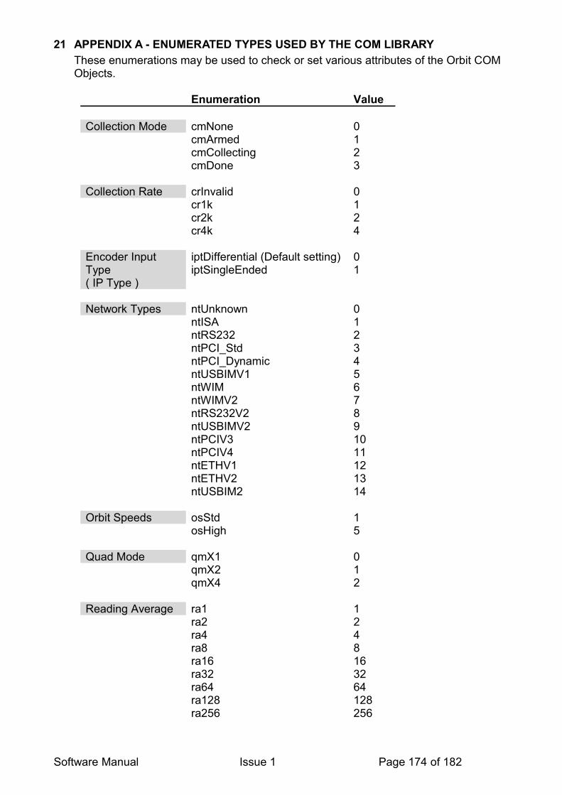
21 APPENDIX A - ENUMERATED TYPES USED BY THE COM LIBRARYThese enumerations may be used to check or set various attributes of the Orbit COM Objects.
Enumeration Value
Collection Mode cmNone 0cmArmed 1cmCollecting 2cmDone 3
Collection Rate crInvalid 0cr1k 1cr2k 2cr4k 4
Encoder Input Type ( IP Type )
iptDifferential (Default setting) 0iptSingleEnded 1
Network Types ntUnknown 0ntISA 1ntRS232 2ntPCI_Std 3ntPCI_Dynamic 4ntUSBIMV1 5ntWIM 6ntWIMV2 7ntRS232V2 8ntUSBIMV2 9ntPCIV3 10ntPCIV4 11ntETHV1 12ntETHV2 13ntUSBIM2 14
Orbit Speeds osStd 1osHigh 5
Quad Mode qmX1 0qmX2 1qmX4 2
Reading Average ra1 1ra2 2ra4 4ra8 8ra16 16ra32 32ra64 64ra128 128ra256 256
Software Manual Issue 1 Page 174 of 182

Reading Resolution
rr14bit 14
rr16bit 16rr18bit 18
Reference Action refactNone 0refactReset_EveryTime 1refactPreset_EveryTime 2refactReset_FirstTime 3refactPreset_FirstTime 4refactReset_FirstTimeAndEnable
5
refactPreset_FirstTimeAndEnable
6
Software Manual Issue 1 Page 175 of 182

22 APPENDIX B - ORBIT NETWORK THROUGHPUTBelow is listed the available speeds for different Orbit Controllers working at different measurement modes (Baud rates). The figures stated here are maximum number of Orbit reads per second. These values are only intended as a guide and will depend heavily on the PC speed, Operating system and number of other applications running.
Orbit3 Timings
RS232 Module Baud Rate Readings/sec(OrbitRead1)
Readings/sec (OrbitRead2)
9600 64 5619200 118 10528800 170 15038400 225 19557600 310 270115200 500 445
PCI Card @ 187.5k Orbit Baud Rate Readings/sec(OrbitRead1)
Readings/sec (OrbitRead2)
187.5 kBaud 1600 1300
PCI Card @ 1.5 M Orbit Baud Rate Readings/sec(OrbitRead1)
Readings/sec (OrbitRead2)
1.5 Mbaud 4400 4070
USBIM Orbit Baud Rate Readings/sec(OrbitRead1)
Readings/sec (OrbitRead2)
187.5 kBaud 490 490
1 Note: Figures obtained are for Orbit Support Pack for Windows Ver 5.0 and above
Software Manual Issue 1 Page 176 of 182

23 APPENDIX C - ORBIT COMPATIBILITY ROADMAP
The Orbit system has evolved over the years and it is now in its third generation.Some features will only be available with newer hardware and some features have been removed over time.A summary of the Orbit commands and hardware with their usage is provided on the following pages.
Software Manual Issue 1 Page 177 of 182

23.1 MODULES
23.1.1 Orbit3
Command *** Digital Probe AIM Linear
Encoder DIOM EIM DIM
OrbitSetaddr
OrbitNotify
OrbitIdentify
OrbitGetinfo
OrbitGetStatus
OrbitRead1
OrbitRead2
OrbitClr
OrbitRst
OrbitAcquireOrbitTriggerOrbitReadiaOrbitDifference
OrbitStartDiff
OrbitStopDiff
OrbitReadDiff1
OrbitReadDiff2
OrbitPreset
OrbitRefmark
OrbitDirectionOrbitSetmode
OrbitControl
OrbitReadBuffer1
OrbitPing
OrbitTconClr
Buffered Mode*
9600 Baud (Very Low Speed)
187500 Baud (Standard / Low Speed)
1500000 Baud (High Speed)
Dynamic Mode
EIM Sync Mode
100 Modules / network
Hot Swap
LEDs
* Buffered Mode is standard*** Digital Probes range includes DP1, DP2, DP5, DP10, DP20, DD, DK, DL, DM, DU, DZ
Software Manual Issue 1 Page 178 of 182

23.1.2 Orbit2
Command *** Digital Probe AIM Linear
Encoder DIOM EIM DIM
OrbitSetaddr
OrbitNotify
OrbitIdentify
OrbitGetinfo
OrbitGetStatus
OrbitRead1
OrbitRead2
OrbitClr
OrbitRst
OrbitAcquireOrbitTriggerOrbitReadiaOrbitDifference
OrbitStartDiff
OrbitStopDiff
OrbitReadDiff1
OrbitReadDiff2
OrbitPreset
OrbitRefmark
OrbitDirection
OrbitSetmode
OrbitControl
OrbitReadBuffer1
Buffered Mode*
9600 Baud (Very Low Speed)
187500 Baud (Standard / Low Speed)
1500000 Baud (High Speed)
Dynamic Mode
EIM Sync Mode
* Buffered Mode was a factory installed option*** Digital Probes range extended to DP1, DP2, DP5, DP10, DP20, DD, DK, DL, DM, DU,DZ
Software Manual Issue 1 Page 179 of 182

23.1.3 Orbit1
Command *** Digital Probe
Linear Encoder DIOM
OrbitSetaddr
OrbitNotify
OrbitIdentify
OrbitGetinfo
OrbitGetStatus
OrbitRead1
OrbitRead2
OrbitClr
OrbitRst
OrbitAcquire
OrbitTrigger
OrbitReadia
OrbitDifference
OrbitStartDiff
OrbitStopDiff
OrbitReadDiff1
OrbitReadDiff2
OrbitPreset
OrbitRefmark
OrbitDirection
OrbitSetmode
OrbitControl
OrbitReadBuffer1
Buffered Mode*
9600 Baud (Very Low Speed)
187500 Baud (Standard / Low Speed)
* Buffered Mode was a factory installed option*** Digital Probes were limited to DP1, DP2, DP5 or DP10
Software Manual Issue 1 Page 180 of 182
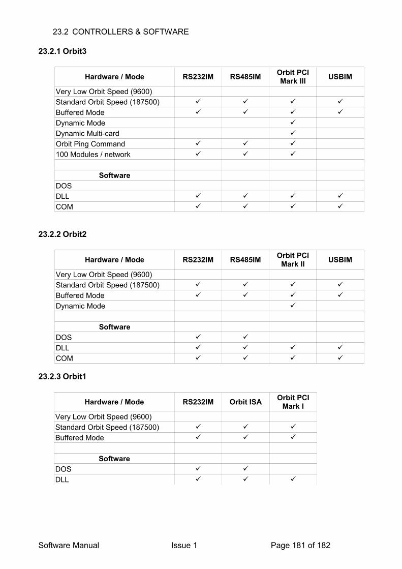
23.2 CONTROLLERS & SOFTWARE
23.2.1 Orbit3
Hardware / Mode RS232IM RS485IM Orbit PCI Mark III USBIM
Very Low Orbit Speed (9600)Standard Orbit Speed (187500)
Buffered Mode
Dynamic Mode
Dynamic Multi-card
Orbit Ping Command
100 Modules / network
SoftwareDOSDLL
COM
23.2.2 Orbit2
Hardware / Mode RS232IM RS485IM Orbit PCI Mark II USBIM
Very Low Orbit Speed (9600)Standard Orbit Speed (187500)
Buffered Mode
Dynamic Mode
SoftwareDOS
DLL
COM
23.2.3 Orbit1
Hardware / Mode RS232IM Orbit ISA Orbit PCI Mark I
Very Low Orbit Speed (9600)Standard Orbit Speed (187500)
Buffered Mode
SoftwareDOS
DLL
Software Manual Issue 1 Page 181 of 182

24 REVISION HISTORY
REVISION DATE COMMENTS1 22/02/10 Initial Issue
Software Manual Issue 1 Page 182 of 182