Embed Size (px)
Citation preview

INSTALLATION, OPERATION AND MAINTENANCE INSTRUCTIONS
Packaged Rooftop Units
50/48 UC-(V)/UP-(V) 025-090
Original document

2
Contents
1 - INTRODUCTION ..................................................................................................................................................... 41.1 - Check equipment received ..................................................................................................................................... 41.2 - Installation safety considerations ........................................................................................................................... 41.3 - Equipment and components under pressure ......................................................................................................... 51.4 - Maintenance safety considerations ........................................................................................................................ 51.5 - Repair safety considerations .................................................................................................................................. 62 - MOVING AND PLACING THE UNIT ...................................................................................................................... 72.1 - Moving .................................................................................................................................................................... 72.2 - Placing the unit ....................................................................................................................................................... 72.3 - Checks before system start-up............................................................................................................................... 83 - INSTALLATION ...................................................................................................................................................... 83.1 - Unit base frame ...................................................................................................................................................... 8 3.2 - Sensor connection and location ............................................................................................................................. 93.3 - Ductwork ................................................................................................................................................................ 93.4 - Condensate and rainwater drainage .................................................................................................................... 104 - DIMENSIONS, CLEARANCES, MM ................................................................................................................... 114.1 - Multiple Rooftop Installation ................................................................................................................................. 145 - PHYSICAL DATA .................................................................................................................................................. 156 - ELECTRICAL DATA ............................................................................................................................................. 177 - APPLICATION DATA ............................................................................................................................................ 187.1 - Air filter replacement............................................................................................................................................. 187.2 - Fan performances, 50/48UCV-UPV 025 .............................................................................................................. 197.3 - Fan performances, 50/48UCV-UPV 035 .............................................................................................................. 197.4 - Fan performances, 50/48UCV-UPV 045 .............................................................................................................. 197.5 - Fan performances, 50/48UCV-UPV 055 .............................................................................................................. 207.6 - Fan performances, 50/48UC-UP 065 ................................................................................................................... 207.7 - Fan performances, 50/48UC-UP 075 ................................................................................................................... 207.8 - Fan performances, 50/48UC-UP 090 ................................................................................................................... 217.9 - Pressure Drops (Pa)............................................................................................................................................. 227.10 - Air Flow Rate Limits.............................................................................................................................................237.11 - Indoor fan air flow adjustment ............................................................................................................................ 238 - ELECTRICAL CONNECTIONS ............................................................................................................................ 238.1 - Control box ........................................................................................................................................................... 238.2 - Power supply ........................................................................................................................................................ 238.3 - Voltage phase imbalance (%)............................................................................................................................... 238.4 - Recommended wire sections ............................................................................................................................... 248.5 - Field control wiring ............................................................................................................................................... 248.6 - Power supply ........................................................................................................................................................ 249 - START-UP ............................................................................................................................................................. 249.1 - Preliminary checks ............................................................................................................................................... 249.2 - Actual start-up ...................................................................................................................................................... 259.3 - Defrost cycle ........................................................................................................................................................ 2510 - MAJOR SYSTEM COMPONENTS ...................................................................................................................... 2510.1 - Compressors ...................................................................................................................................................... 2510.2 - Lubricant............................................................................................................................................................. 2510.3 - Condensers ........................................................................................................................................................ 2510.4 - Outdoor fans....................................................................................................................................................... 2510.5 - Indoor fans ......................................................................................................................................................... 2610.6 - Electronic expansion valve (EXV) ...................................................................................................................... 2610.7 - Moisture indicator ............................................................................................................................................... 2610.8 - Filter drier ........................................................................................................................................................... 2610.9 - Refrigerant.......................................................................................................................................................... 26

3
10.10 - Four-way valve (50/48 UP-(V) heat pumps) ..................................................................................................... 2610.11 - Sensors ............................................................................................................................................................ 2610.12 - High-pressure safety switch ............................................................................................................................. 2610.13 - Variable Frequency Driver(VFD) ...................................................................................................................... 26 11 - OPERATING LIMITS ....................................................................................................................................... 2612 - GAS HEATING (48UC(V)/UP(V) ONLY) .......................................................................................................... 2712.1 - Introduction......................................................................................................................................................... 2712.2 - Preliminary checks before start-up ..................................................................................................................... 2712.3 - Safety instructions .............................................................................................................................................. 2812.4 - Installation of the gas heating module ................................................................................................................ 2812.5 - Commissioning ................................................................................................................................................... 3012.6 - Combustion Analysis .......................................................................................................................................... 3112.7 - Operating sequence ........................................................................................................................................... 3212.8 - Maintenance operations ..................................................................................................................................... 3312.9 - Control of PCH heater ........................................................................................................................................ 3413 - OPTION ........................................................................................................................................................... 3613.1 - Electric heaters................................................................................................................................................... 3613.2 - Hot-water coil ..................................................................................................................................................... 3613.3 - Economizer options (thermostatic or enthalpic) ................................................................................................. 3613.4 - Manual outside air damper ................................................................................................................................. 3813.5 - Economizer with CO2 sensor options (thermo-static or enthalpic) ...................................................................... 3913.6 - Power exhaust option ......................................................................................................................................... 3913.7 - Return air fan options ......................................................................................................................................... 4113.8 - Dirty filter detection option .................................................................................................................................. 4513.9 - Smoke detector .................................................................................................................................................. 4513.10 - Fire thermostat ................................................................................................................................................. 4513.11 - Thermodynamic Energy Recovery (THR) ........................................................................................................ 4513.12 - Energy Recovery Module (ERM)...................................................................................................................... 4614 - ACCESSORIES ............................................................................................................................................... 5114.1 - Roofcurbs .......................................................................................................................................................... 5115 - STANDARD MAINTENANCE .......................................................................................................................... 5215.1 - Maintenance program ........................................................................................................................................ 5215.2 - Maintenance instructions.................................................................................................................................... 5215.3 - Level 1 maintenance .......................................................................................................................................... 5215.4 - Level 2 maintenance .......................................................................................................................................... 5315.5 - Level 3 (or higher) maintenance......................................................................................................................... 5315.6 - Tightening torques for main electrical connections ............................................................................................ 5415.7 - Tightening torques for the main bolts and screws .............................................................................................. 5415.8 - Indoor/outdoor coils ............................................................................................................................................ 5515.9 - Refrigerant volume ............................................................................................................................................. 5515.10 - Characteristics of R410A .................................................................................................................................. 5615.11 - Servicing recommendations ............................................................................................................................. 5715.12 - Final recommendations .................................................................................................................................... 5715.13 - Troubleshooting chart ....................................................................................................................................... 5716 - START-UP CHECKLIST FOR 48/50UC(V)-UP(V) ROOFTOP UNITS (USE FOR JOB FILE) ....................... 5817 - GAS HEATING SECTION ............................................................................................................................... 61
NOTES FOR 48 SERIES UNITS FITTED WITH A GAS BURNER
IMPORTANT: The appliance must be installed in accordance with local safety codes and regulations and is intended for outdoor use only.
Please read the manufacturer’s instructions carefully before starting this unit.
CAUTION: Before installation, check that the local distribution conditions, type of gas and available pressure, and the power supply and adjustments of the appliance are correct.
The drawings in this document are for illustrative purposes only and is not part of any offer for sale or contract.

4
1 - INTRODUCTIONPrior to the initial start-up of the 50/48 UC-(V)/UP-(V) units, the people involved should be thoroughly familiar with these instructions and the specific project data for the installation site. The 50/48 UC-(V)/UP-(V packaged rooftop units are designed to provide a very high level of safety and reliability making installation, start-up, operation and maintenance easier and more secure. They will provide safe and reliable service when operated within their application range.
They are designed for an operating life of 15 years by assuming a 75% utilization factor; that is approximately 100,000 operating hours.
The procedures in this manual are arranged in the sequence required for machine installation, start-up, operation and maintenance.
Be sure you understand and follow the procedures and safety precautions contained in the instructions supplied with the machine, as well as those listed in this guide, such as: protective clothing such as gloves, safety glasses, safety shoes and appropriate tools, and suitable qualifications (electrical, air conditioning, local legislation).
To find out, if these products comply with European directives (machine safety, low voltage, electromagnetic compatibility, equipment under pressure, etc.) check the declarations of conformity for these products.
1.1 - Check Equipment Received
• Inspecttheunitfordamageormissingparts.Ifdamageis detected, or if shipment is incomplete, immediately file a claim with the shipping company.
• Confirmthattheunitreceivedistheoneordered.Compare the name plate data with the order.
• Thenameplateisattachedtotheunitontheoutsideon one of the unit sides
• Theunitnameplatemustincludethefollowinginformation:
- Model number - size
- CE marking
- Serial number
- Year of manufacture and pressure and leak tightness test date
- Refrigerant used
- Refrigerant charge per circuit
- PS: Min/max allowable pressure (high and low pressure side) - see chapter 11
- TS: Min/max allowable temperature (high and low pressure side) - see chapter 11
- Pressure switch cut-out pressure
- Unit leak test pressure
- Voltage, frequency, number of phases
- Maximum current input
- Maximum power input
- Unit net weight
• Confirmthatalloptionsorderedforon-siteinstalla-
tion have been delivered, are complete and undamaged.
The unit must be checked periodically during its whole operating life for possible damage of the insulation (thermal, acoustic) to ensure that no shocks (handling accessories, tools, etc.) have damaged it. If necessary, the damaged insulation parts must be repaired or replaced. See also chapter “Maintenance”.
1.2 - Installation Safety Considerations
After the unit has been received, and before it is started up, it must be inspected for damage. Check that the refrigerant circuits are intact, especially that no components or pipes have shifted or been damaged (e.g. following a shock). If in doubt, carry out a leak tightness check. If damage is detected upon receipt, immediately file a claim with the shipping company or repair.
The unit must be installed in a place that is not accessible to the public or protected against access by non-authorised persons.
The unit should not be installed in an explosive atmosphere. Do not remove the skid or the packaging until the unit is
in its final position. These units can be moved with a forklift truck, as long as the forks are positioned in the right place and direction on the unit.
The units can also be lifted with slings, using only the designated lifting points marked on the unit (labels on the chassis and a label with all unit handling instructions are attached to the unit).
Use slings with the correct capacity, and always follow the lifting instructions on the certified drawings supplied for the unit.
This unit is designed for ducted installation (indoor air supply and return). If ducts are not used the installer must place a protection grille in the supply and return.
Safety is only guaranteed, if these instructions are carefully followed. If this is not the case, there is a risk of material deterioration and injuries to personnel.
These units are not designed to be lifted from above.
All precautions concerning handling of refrigerant must be observed in accordance with local regulations.
Accumulation of refrigerant in an enclosed space can displace oxygen and cause asphyxiation or explosions.
Inhalation of high concentrations of refrigerant is harmful and may cause heart irregularities, unconsciousness, or death. Refrigerant is heavier than air and reduces the amount of oxygen available for breathing. These products cause eye and skin irritation. Decomposition products can be hazardous.

5
1.3 - Equipment and Components Under Pressure
These products incorporate equipment or components under pressure, manufactured by Carrier or other manufacturers.
We recommend that you consult your appropriate national trade association or the owner of the equipment or components under pressure (declaration, re-qualification, retesting, etc.). The characteristics of this equipment/these components are given on the nameplate or in the required documentation, supplied with the products.
The units are intended to be stored and operate in an environment where the ambient temperature must not be less than the lowest allowable temperature indicated on the nameplate.
Do not introduce high static and dynamic pressure compared with the existing operating pressures - either service or test pressures in the refrigerant circuit.
1.4 - Maintenance Safety Considerations
Carrier recommends the following drafting for a logbook (the table below should not be considered as reference and does not involve Carrier responsibility):
Date Operation*
*Maintenance, repairs, regular verifications (EN 378), leakage, etc.
Intervention Name of the Commissioning
Engineer
Applicable National
Regulations
Verification Organism
Engineers working on the electric or refrigeration or gas heating components must be authorized, trained and fully qualified to do so (e.g. electricians trained and qualified in accordance with IEC 60364 Classification BA4).
All refrigerant circuit work must be carried out by a trained person, fully qualified to work on these units. They must have
been trained and be familiar with the equipment and the installation. All welding operations must be carried out by qualified specialists.
These units use high pressure R410A refrigerant (the unit operating pressure is above 40 bar, the pressure at 35 °C air temperature is 50% higher than R22). Special equipment must be used when working on the refrigerant circuit (pressure gauge, charge transfer, etc.).
Any manipulation of a refrigerant recovery valve must be carried out by a qualified and authorized engineer,
observing applicable standards (e.g. during refrigerant removal). The unit must be switched off while this is done.
Equip the engineers that work on the unit as follows:
Never work on a unit that is still energized. Never work on any of the electrical components, until the general power supply to the unit has been cut.
If any maintenance operations are carried out on the unit, lock the power supply circuit in the open position and secure the machine upstream with a padlock.
If the work is interrupted, always ensure that all circuits are still deenergized before resuming the work.
ATTENTION: Even if the unit has been switched off, the power circuit remains energized, unless the unit or circuit disconnect switch is open. Refer to the wiring diagram for further details. Attach appropriate safety labels.
If any work is carried out in the fan area, specifically if the grilles or casings have to be removed, cut the power supply to the fans to prevent their operation.
OPERATING CHECKS:
Important information regarding the refrigerant used:
This product contains fluorinated greenhouse gas covered by the Kyoto protocol.
Refrigerant type: R410A
Global Warming Potential (GWP): 2,088 CAUTION:
1. Any intervention on the refrigerant circuit of this product should be performed in accordance with the applicable legislation. In the EU, the regulation is called F-Gas, N°517/2014.
2. Ensure that the refrigerant is never released to the atmosphere during installation, maintenance or equipment disposal.
3. The deliberate gas release into the atmosphere is not allowed
4. If a refrigerant leak is detected, ensure that it is stopped and repaired as quickly as possible.
Handling Maintenance, Service Welding or Brazing**
Protective gloves, eye protection, safety shoeProtective clothing x x xEar protection x xFiltering respirator x x x
*We recommend to follow the instructions in EN 378-3.**Performed in the presence of A1 refrigerant according to EN 378-1.
OperationsPersonal Protection Equipment (PPE)*

6
5. Only a qualified and certified personnel can perform installation operations, maintenance, refrigerant circuit leak test as well as the equipment disposal and the refrigerant recovering.
6. The gas recovery for recycling, regeneration or destruc- tion is at customer charge.
7. Periodic leak tests have to be carried out by the customer or by third parties. The EU regulation set the periodicity here after:
8. A logbook must be established for equipments subject to periodic leak tests. It should contain the quantity and the type of refrigerant present within the installation (added and recovered), the quantity of recycled refrigerant, regenerated or destroyed, the date and output of the leak test, the designation of the operator and its belonging company, etc.
9. Contact your local dealer or installer if you have any questions.
Protection device checks:
• Ifnonationalregulationsexist,checktheprotectiondevices on site in accordance with standard EN378: once a year for the high-pressure switches.
The company or organization that conducts a pressure switch test shall establish and implement a detailed procedure to fix:
- Safety measures
- Measuring equipment calibration
- Validating operation of protective devices
- Test protocols
- Recommissioning of the equipment.
Consult Carrier Service for this type of test. Carrier mentions here only the principle of a test without removing the pressure switch:
- Verify and record the set-points of pressure switches
- Be ready to switch-off the main disconnect switch of the power supply if the pressure switch does not trigger (avoid over pressure)
- Connect a calibrated pressure gauge (the values displayed on the user interface may be inaccurate in an instant reading because of the scanning delay applied in the control)
- Activate the HP quick test included in the control procedure.
CAUTION: If the test leads to replacing the pressure switch, it is necessary to recover the refrigerant charge, these pressure switches are not installed on automatic valves (Schrader type).”
At least once a year thoroughly inspect the protection devices. If the machine operates in a corrosive environment, inspect the protection devices more frequently.
Regularly carry out leak tests and immediately repair any leaks.
Ensure regularly that the vibration levels remain acceptable and close to those at the initial unit start-up.
Before opening a refrigerant circuit, transfer the refrigerant to bottles specifically provided for this purpose and consult the pressure gauges.
Change the refrigerant after an equipment failure, and carry out a refrigerant analysis in a specialist laboratory.
If the refrigerant circuit remains open for longer than a day after an intervention (such as a component replacement), the openings must be plugged and the circuit must be charged with nitrogen (inertia principle). The objective is to prevent penetration of atmospheric humidity and the resulting corrosion on the internal walls and on non-protected steel surfaces.
1.5 - Repair Safety Considerations
All installation parts must be maintained by the personnel in charge, in order to avoid deterioration and injury. Faults and leaks must be repaired immediately. The authorized technician must have the responsibility to repair the fault immediately. After each repair of the unit, check the opera- tion of the protection devices and create a report of the parameter operation at 100%.
No Check 12 Months 6 Months 3 Months
No Check 24 Months 12 Months 6 Months
< 5 Tons 5 ≤ Charge < 50 Tons 50 ≤ Charge < 500 Tons Charge > 500 Tons*
R134a (GWP: 1,430) Charge < 3.5 kg 3.5 ≤ Charge < 34.9 kg 34.9 ≤ Charge < 349.7 kg Charge > 349.7 kg
R407C (GWP: 1,774) Charge < 2.8 kg 2.8 ≤ Charge < 28.2 kg 28.2 ≤ Charge < 281.9 kg Charge > 281.9 kg
R410A (GWP: 2,088) Charge < 2.4 kg 2.4 ≤ Charge < 23.9 kg 23.9 ≤ Charge < 239.5 kg Charge > 239.5 kg
HFO's: R1234ze
*From 01/01/2017, units must be equipped with a leakage detection system
System WITHOUT Leakage detection
System WITH Leakage detection
Refrigerant Charge/Circuit (CO2
Equivalent)
Refrigerant Charge (kg)
No Requirement

7
Comply with the regulations and recommendations in unit and HVAC installation safety standards, such as: EN 378, ISO 5149, etc.
RISK OF EXPLOSION
Never use air or a gas containing oxygen during leak tests to purge lines or to pressurize a machine. Pressurized air mixtures or gases containing oxygen can be the cause of an explosion. Oxygen reacts violently with oil and grease.
Only use dry nitrogen for leak tests, possibly with an appropriate tracer gas.
If the recommendations above are not observed, this can have serious or even fatal consequences and damage the installation.
Never exceed the specified maximum operating pressures. Verify the allowable maximum high and low side test pressures by checking the instructions in this manual and the pressures given on the unit name plate.
Do not unweld or flamecut the refrigerant lines or any refrigerant circuit component until all refrigerant (liquid and vapour) and the oil have been removed from the unit. Traces
of vapour should be displaced with dry nitrogen. Refrigerant in contact with an open flame can produce toxic gases.
The necessary protection equipment must be available, and appropriate fire extinguishers for the system and the refrigerant type used must be within easy reach.
Do not siphon refrigerant. Avoid spilling liquid refrigerant
on skin or splashing it into the eyes. Use safety goggles and safety gloves. Wash any spills from the skin with soap and water. If liquid refrigerant enters the eyes, immediately and abundantly flush the eyes with water and consult a doctor.
The accidental releases of the refrigerant, due to small leaks or significant discharges following the rupture of a pipe or an unexpected release from a relief valve, can cause frostbites and burns to personnel exposed. Do not ignore such injuries. Installers, owners and especially service engineers for these units must:
- Seek medical attention before treating such injuries.
- Have access to a first-aid kit, especially for treating eye injuries.
We recommend to apply standard EN 378-3 Annex 3.
Never apply an open flame (blow lamp) or overheated steam (high-pressure cleaner) to the refrigerant circuit. Dangerous overpressure can result.
During refrigerant removal and storage operations follow applicable regulations. These regulations, permitting conditioning and recovery of halogenated hydrocarbons under optimum quality conditions for the products and optimum safety conditions for people, property and the environment are described in standard NF E29-795.
Refer to the certified dimensional drawings for the units.
It is dangerous and illegal to re-use disposable (non-return- able) cylinders or attempt to refill them. When cylinders are empty, evacuate the remaining gas pressure, and move them to a designated place for recovery. Do not incinerate.
Do not attempt to remove refrigerant circuit components or fittings, while the machine is under pressure or while it is running. Be sure pressure is at 0 kPa and that the unit has been shut-down and deenergised before removing components or opening a circuit.
Do not attempt to repair or recondition any safety devices when corrosion or build-up of foreign material (rust, dirt, scale, etc.) is found within the valve body or mechanism. If necessary, replace the device.
ATTENTION: No part of the unit must be used as a walkway, rack or support. Periodically check and repair or if necessary replace any component or piping that shows signs of damage.
Do not step on refrigerant lines. The lines can break under the weight and release refrigerant, causing personal injury.
Do not climb on a machine. Use a platform, or staging to work at higher levels.
Use mechanical lifting equipment (crane, hoist, winch, etc.) to lift or move heavy components. For lighter components, use lifting equipment when there is a risk of slipping or losing your balance.
Use only original replacement parts for any repair or component replacement. Consult the list of replacement parts that corresponds to the specification of the original equipment.
Periodically inspect all valves, fittings and pipes of the refrigerant and hydronic circuits to ensure that they do not show any corrosion or any signs of leaks.
It is recommended to wear ear defenders, when working near the unit and the unit is in operation.
Always ensure you are using the correct refrigerant type before recharging the unit.
Charging any refrigerant other than the original charge type (R410A) will impair machine operation and can even lead to a destruction of the compressors. The compressors operate with R410A and are charged with an oil.
Before any intervention on the refrigerant circuit, the complete refrigerant charge must be recovered.
2 - MOVING AND PLACING THE UNIT
2.1 - Moving
See chapter 1.2 – “Installation safety considerations”.
2.2 - Placing the Unit
The machine must be installed in a place that is not accessible to the public or protected against access by non-authorized persons.
In case of extra-high units the machine environment must permit easy access for maintenance operations.
Always refer to the chapter “Dimensions and clearances”

8
to confirm that there is adequate space for all connections and service operations. For the center of gravity coordinates, the position of the unit mounting holes, and the weight distribution points, refer to the certified dimensional drawing supplied with the unit.
Typical applications of these units do not require earthquake resistance. Earthquake resistance has not been verified.
CAUTION: Only use slings at the designated lifting points which are marked on the unit
Before placing the unit check that:
• Thepermittedloadingatthesiteisadequateorthatappropriate strengthening measures have been taken.
• Theunitisinstalledlevelonanevensurface(maximumtolerance is 5 mm in both axes).
• Thereisadequatespaceabovetheunitforairflowandto ensure access to the components (see dimensional drawings).
• Thenumberofsupportpointsisadequateandthattheyare in the right places.
• Thelocationisnotsubjecttoflooding
• Ifheavysnowfallislikelyandlongperiodsofsub-zerotemperatures are normal, provision has to be made to prevent snow accumulating by raising the unit above the height of drifts normally experienced. Baffles may be necessary to deflect strong winds. They must not restrict air flow into the unit.
CAUTION: Before lifting the unit, check that all casing panels are securely fixed in place. Lift and set down the unit with great care. Tilting and jarring can damage the unit and impair unit operation.
If units are hoisted with rigging, it is advisable to protect coils against crushing while a unit is being moved. Use struts or a lifting beam to spread the slings above the unit. Do not tilt a unit more than 15°.
WARNING: Never push or lever on any of the enclosure panels of the unit. Only the base of the unit frame is designed to withstand such stresses.
2.3 - Checks Before System Start-up
Before the start-up of the refrigeration system, the complete installation, including the refrigeration system must be verified
against installation drawings, dimensional drawings, system piping and instrumentation diagrams and the wiring diagrams.
Follow national regulations for these checks. If the national regulation does not specify any details, refer to standard EN 378-2 as follows: External visual installation checks:
• Ensurethatthemachineischargedwithrefrigerant.Verify on the unit nameplate that the ‘fluid being transported’ is R410A and is not nitrogen.
• Comparethecompleteinstallationwiththerefrigeration system and power circuit diagrams.
• Checkthatallcomponentscomplywiththedesignspecifications
• Checkthatallprotectiondocumentsandequipmentprovided by the manufacturer (dimensional drawings, P&ID, declarations etc.) to comply with the regulations are present.
• Verifythattheenvironmentalsafetyandprotectionand devices and arrangements provided by the manufacturer to comply with the regulations are in place.
• Verifythatalldocumentsforpressurecontainers,certificates, name plates, files, instruction manuals provided by the manufacturer to comply with the regulations are present.
• Verifythefreepassageofaccessandsafetyroutes.
• Verifytheinstructionsanddirectivestopreventthedeliberate removal of refrigerant gases.
• Verifytheinstallationofconnections.
• Verifythesupportsandfixingelements(materials,routing and connection).
• Verifythequalityofweldsandotherjoints.
• Checktheprotectionagainstmechanicaldamage.
• Checktheprotectionagainstheat.
• Checktheprotectionofmovingparts.
• Verifytheaccessibilityformaintenanceorrepairandto check the piping.
• Verifythestatusofthevalves.
• Verifythequalityofthethermalinsulationandofthevapor barriers.
• Ensurethattheventilationinthemachineroomissufficient
• Checktherefrigerantdetectors.
3 - INSTALLATION
3.1 - Unit Base Frame
This unit is for connection to a ducted air system only. It should not be used without ductwork connected to the air outlet or supply side of the unit. It is possible to provide fresh air to the unit air inlet side without the use of ductwork via an optional kit containing a damper system, and protective hood and grilles. Consult the unit supplier or distributor for more information.
Due to the size and weight of the units the base frame must be on a support which fulfils the following requirements:
- The surface area must be sufficient for disturbing the unit weight over the building structure.
- Sufficient drain holes should be provided to avoid the
accumulation of rain water.
- The unit should be firmly fixed to the floor
- The structure should be capable of supporting the unit weight during installation and operation.

9
Fig. 1 – Roofcurb accessory – standard vertical supply and return
- The standard unit leaves the factory with the air supply and return in the lower section (see Fig. 1) and the corresponding holes on the roof must be made.
Refer to the certified dimensional drawings for the supply and return openings.
The unit air supply and return can be from side or top as an option (See Fig. 2a) and also side return and supply via top plenum (See Fig. 2b).
Fig. 2a – Duct configuration standard/optional
Fig. 2b – Duct configuration via top plenum optional
3.2 - Sensor Connection and Location
The room temperature sensor and supply temperature sensor are located in the control box together with their connectors. Please refer to the wiring diagrams for the required connec- tions and suitable cable diameter. Criteria for selecting sensor locations will vary with system and building specifics
Recommended sensor locations are shown in Fig. 3.
NOTE: The return duct sensor or the room temperature sensor can be used.
Fig. 3 – Recommended sensor location
3.3 - Ductwork
It is necessary to use adequate sealants and joints to ensure correct fitting and water-tightness between the ducts and the support so that air and moisture do not enter the building.
WARNING: Do not drill any holes in the indoor coil area as this might damage the condensate drain pan.
IMPORTANT: The unit should be correctly levelled to avoid drainage problems.
Determine the ductwork dimensions according to the air flow to be carried, and the available static pressure. The different air flows and static pressures that each unit can supply, are shown in the fan performance tables
It is recommended to observe the following considerations:
• Whatevertypeofductworkisused,itshouldnotbemade of materials which are flammable or which give off toxic gases in the event of a fire. The internal surfaces should be smooth, and not contaminate the air which passes through. It is recommended to use sheet metal ducts which are adequately insulated to avoid conden- sation and thermal leakage.
• Atthepointswheretheductsjointheunit,itisrecommended to use flexible connections which absorb

10
Fig. 4a – Examples for good and bad connections: Fig. 4b – Some bad examples on site
Fig. 5 – Condensate drain pipe details
3.4 - Condensate and Rainwater Drainage
The units incorporate drill holes in the base near the outdoor coils to drain rain water and condensation. The indoor heat exchanger area incorporates a drain pan with an outside drain pipe diameter of 34 mm and a negative drainage siphon as in Fig. 5.
Min. recommended value of X is 180 mm.
vibrations, prevent noise inside the ductwork and allow access to the unit.
• Bendsneartheunitoutletshouldbeavoidedasmuchas possible. If unavoidable, they should be as slight as possible, and internal deflectors should be used when the duct has large dimensions.
Below are some obligations for ductwork:
All ducts should have radial bends. It is highly recommended that no sheets of ductwork have right angle bend.
If duct is directed towards right/left of supply air outlet or there is any change in duct diameter, the ductwork should go downward for at least 2 m before any bend or diameter change (see Fig. 4a). If no change in diameter or direction is involved, it is not obliged.
It is essential to abide by the rules above for all units with gas heating option (48 UC-(V)/UP-(V))
NOTE: All duct sizing and design work should be carried out by qualified technicians.

11
4- DIMENSIONS, CLEARANCES, mm
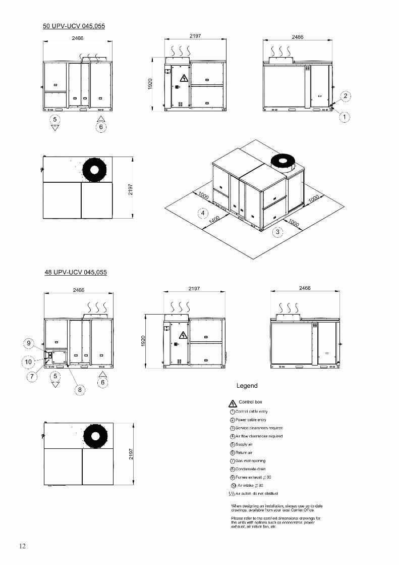
12

13

14
4.1 - Multiple Rooftop Installation
For 025-035-045-055 sizes; For 065-075-090 sizes;025-035-045-055 modelleri için; 065-075-090 modelleri için;For 025-035-045-055 sizes;
Note: If the walls are higher than 2.4 m, contact the factory.
For 065-075-090 sizes;

15
5 - PHYSICAL DATA
Unit 025 035 045 055 065 075 090
kW 22,4 33,3 41,8 54,7 64,1 76,4 85,0
kW 6,9 10,1 13,9 17,3 18,6 22,3 25,7
kW/kW 3,24 3,29 3,01 3,17 3,45 3,43 3,30
A A A A A A A
4,09 4,78 4,38 4,44 4,36 4,45 4,09
161 188 172 175 171 175 161
Unit 025 035 045 055 065 075 090
kW 22,4 33,3 41,8 52,8 64,1 76,4 86,1
kW 6,9 10,1 13,9 17,2 18,6 22,3 25,9
kW/kW 3,24 3,29 3,01 3,07 3,45 3,43 3,32
A A A A A A A
4,09 4,78 4,38 4,37 4,36 4,45 4,11
161 188 172 172 171 175 161
kW 24,5 35,1 46,7 58,4 65,0 81,6 93,1
kW 7,0 9,4 12,6 15,0 17,6 22,5 25,9
kW/kW 3,51 3,75 3,71 3,90 3,69 3,63 3,59
A A A A A A A
3,21 3,58 3,61 3,79 3,33 3,39 3,33
125 140 141 149 130 133 130
Unit 025 035 045 055 065 075 090
kW 18 18 27 27 36 36 45
9+9 9+9 9+9+9 9+9+9 9+9+18 9+9+18 9+18+18
A 26 26 39 39 52 52 65
Unit 025 035 045 055 065 075 090
kW 7,6 / 34,85 7,6 / 34,85 8,5 / 42,00 8,5 / 42,00 12,4 / 65,00 12,4 / 65,00 12,4 / 65,00
kW 8,13 / 33,56 8,13 / 33,56 8,97 /40,45 8,97 /40,45 13,4 / 62,93 13,4 / 62,93 13,4 / 62,93
% 107 / 96 107 / 96 106 / 96 106 / 96 108 / 97 108 / 97 108 / 97
m3/h 0,80 / 3,69 0,80 / 3,69 0,90 / 4,44 0,90 / 4,44 1,31 / 6,88 1,31 / 6,88 1,31 / 6,88
kg 48 48 58 58 72 72 72
W 11 / 74 11 / 74 15 / 65 15 / 65 15 / 97 15 / 97 15 / 97
pcs 1 / 1 1 / 1 1 / 1 1 / 1 2 / 4 2 / 4 2 / 4
kg 9 / - 10.5 / - 12 / - 15 / - 12 / 12 15 / 15 15 / 15
kg 9 / - 10,5 / - 12 / - 15 / - 12 / 12 15,5 / 15,5 15,5 / 15,5
kg 1,3 / - 1,6 / - 3,3 / - 3,6 / - 3,2 / 3,2 3,2 / 3,2 3,2 / 3,2
Cu / Al Cu / Al Cu / Al Cu / Al Cu / Al Cu / Al Cu / Al
3/8" RTPF 3/8" RTPF 3/8" RTPF 3/8" RTPF 3/8" RTPF 3/8" RTPF 3/8" RTPF
2 / 16 3 / 16 3 / 16 4 / 16 3 / 16 4 / 16 4 / 16
mm 34 34 34 34 34 34 34
Cu / Al Cu / Al Cu / Al Cu / Al Cu / Al Cu / Al Cu / Al
3/8" RTPF 3/8" RTPF 3/8" RTPF 3/8" RTPF 3/8" RTPF 3/8" RTPF 3/8" RTPF
2 / 16 2 / 16 2 / 16 3/ 16 2 / 16 3 / 16 3 / 16
*Nominal Eurovent conditions: outdoor air dry bulb temperature of 35 °C, indoor air wet bulb temperature of 19 °C.
**Nominal Eurovent conditions: outdoor air wet bulb temperature of 6 °C, indoor air dry bulb temperature of 20 °C.
***According to Commission Regulation (EU) 2016/2281 and related standard EN14825:2016.
****Natural gas (G20) net calorific value 34.02 MJ/m3 @ 15°C, 1,013 mbar.
*****Weight and power input values are valid for the heating modules.
Condensate Drain Connection Size
Outdoor Coil
Material
Coil Type
Rows / FPI
50UC Charge: Circuit A - Circuit B
Oil: Circuit A - Circuit B
Indoor Coil
Material
Coil Type
Rows / FPI
Compressor Type Scroll
Refrigerant R410A
No of Circuits / No of Compressors
50UP Charge: Circuit A - Circuit B
Modulating
Weight****
Power Input ( 230 V-1 Ph-50 Hz )*****
Gas Connection UNI/ISO 228/1-G 3/4"
Refrigeration System
Gas Heaters
Net Heat Input (Min / Max)
Heat Output (Min / Max)
Efficiency
Natural Gas Rate (G20)****
Capacity Steps
50 UC/UP-(V)
Electric Heaters (Only 50 Series)
Heating Capacity
Capacity Steps
Rated Current
48 UC/UP-(V)
Nominal Heating Capacity**
Nominal Power Input
COP**
Eurovent Energy Class Heating
SCOP***
ηs,h***
Nominal Power Input
EER*
Eurovent Energy Class Cooling
SEER***
ηs,c***
Heating
SEER***
ηs,c***
50/48 UP-(V)
Eurovent Performances at EN14511-2018
Cooling
Nominal Cooling Capacity*
50/48 UC-(V)
Eurovent Performances at EN14511-2018
Nominal Cooling Capacity*
Nominal Power Input
EER*
Eurovent Energy Class Cooling

16
025 035 045 055 065 075 090
pcs 1 1 1 1 2 2 2
kW 0,84 0,84 1,83 1,76 0,84 1,76 1,76
rpm 720 / 500 720 / 500 970 / 485 970 / 485 720 / 500 970 / 485 970 / 485
m3/h 11.988 12.168 18.144 17.712 24.768 35.424 35.424
mm 775 775 775 775 775 775 775
dB(A) 80,7 81,7 82,7 83,2 83,8 83,9 84dB(A) 45,8 46,8 47,8 48,3 48,7 48,8 48,9
pcs 1 1 1 1 1 1 1
pcs 1 1 1 1 1 1 1
mm 400 400 450 560 560 560 560
m3/h 4.205 5.886 7.568 9.250 10.463 11.533 12.500
rpm 1.000 / 2.480 1.300 / 2.480 1.120 / 2.140 830 / 1.540 840 / 1.540 900 / 1.540 970 / 1.540
kW 2,5 2,5 2,9 3,3 3,3 3,3 3,3
Pa 50 50 50 50 50 50 50
Pa 1.150 850 850 750 650 550 450
pcs N/A N/A N/A N/A N/A 2 2
pcs N/A N/A N/A N/A N/A 2 2
N/A N/A N/A N/A N/A
mm N/A N/A N/A N/A N/A 560 560
m3/h N/A N/A N/A N/A N/A 11.533 12.500
rpm N/A N/A N/A N/A N/A 1.300 / 2.470 1.380 / 2.470
kW N/A N/A N/A N/A N/A 2,5 2,5
Pa N/A N/A N/A N/A N/A 50 50
Pa N/A N/A N/A N/A N/A 850 750
pcs 4 4 6 6 9 9 9
mm 610 x 610 x 50 610 x 610 x 50 610 x 480 x 50 610 x 480 x 50 565 x 565 x 50 565 x 565 x 50 565 x 565 x 50
kg 730 790 850 900 1.460 1.540 1.540
kg 800 860 927 977 1.557 1.637 1.637
kg 727 785 844 894 1.452 1.532 1.532
kg 797 855 921 971 1.549 1.629 1.629
mm 2.466 2.466 2.466 2.466 3.608 3.608 3.608
mm 2.196 2.196 2.196 2.196 2.196 2.196 2.196
mm 1.716 1.716 1.918 1.918 2.084 2.084 2.084
*The values have been rounded, for information only and calculated according to ISO 9614-1 standard.
**For information, calculated from the sound power level Lw(A)
***For standard unit at nominal air flow without options
48UC
General Dimensions (Without Options)
Length
Width
Height
Quantity
Filter Size
Operating Weight (Without Options)
50UP
48UP
50UC
Nominal Air Flow Rate
Motor Speed Range (Min / Max)
Motor Power Input
Static Pressure Available***
Maximum Static Pressure Available***
Filters
High Static Pressure
Motor Quantity
Fan Quantity
Type EC Plug
Fan Diameter
Fan Diameter
Nominal Air Flow Rate
Motor Speed Range (Min / Max)
Motor Power Input
Static Pressure Available***
Maximum Static Pressure Available***
Indoor Fan / Motor
Standard Static Pressure
Motor Quantity
Fan Quantity
Type EC Plug
Motor Speed (High / Low)
Total Air Flow Rate
Fan Diameter
Sound Levels
Sound Power Level 10-12 W*
Sound Pressure Level at 10 m**
50/48 UC/UP-(V)
Outdoor Fan / Motor
Type Direct Driven Axial
Fan Quantity
Motor Power Input (Each)
17
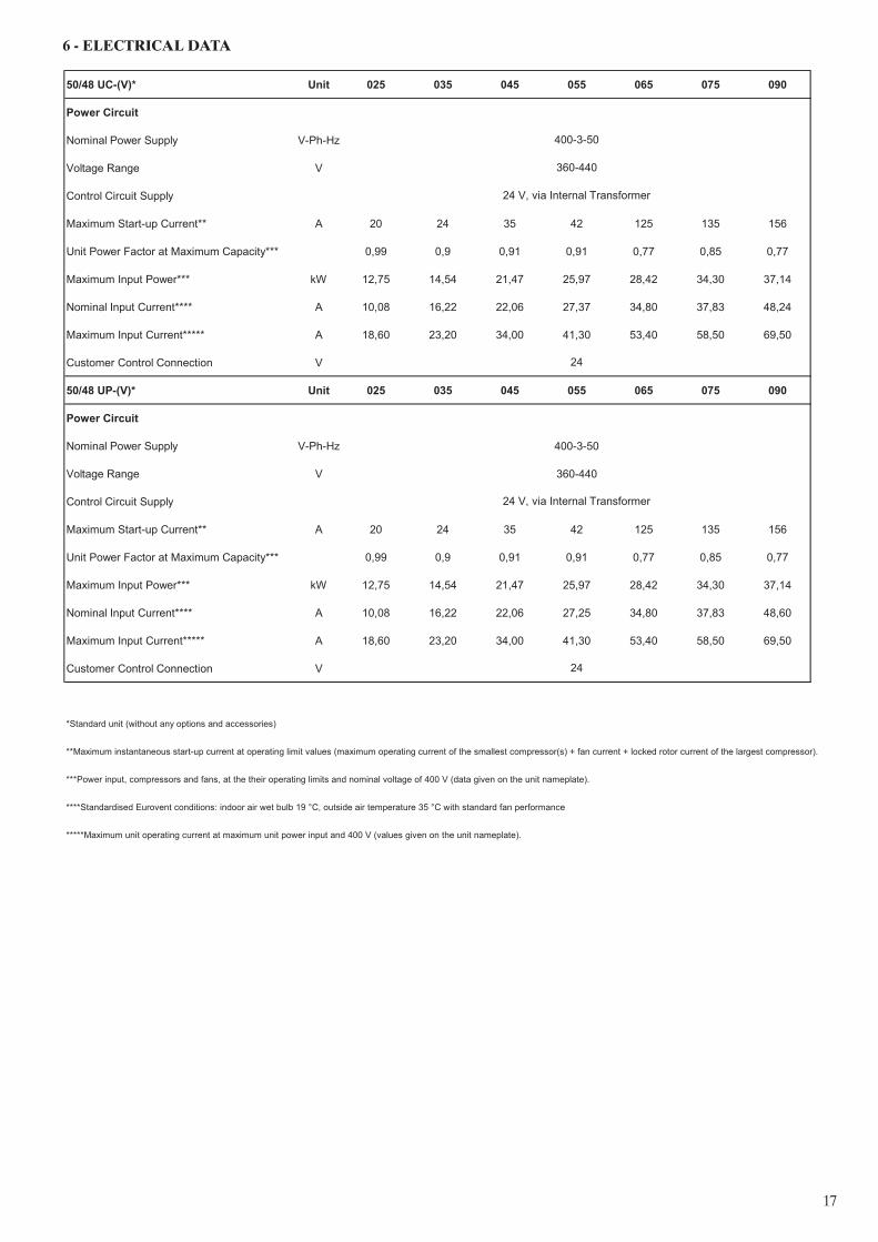
6 - ELECTRICAL DATA
50/48 UC-(V)* Unit 025 035 045 055 065 075 090
Power Circuit
Nominal Power Supply V-Ph-Hz
Voltage Range V
Control Circuit Supply
Maximum Start-up Current** A 20 24 35 42 125 135 156
Unit Power Factor at Maximum Capacity*** 0,99 0,9 0,91 0,91 0,77 0,85 0,77
Maximum Input Power*** kW 12,75 14,54 21,47 25,97 28,42 34,30 37,14
Nominal Input Current**** A 10,08 16,22 22,06 27,37 34,80 37,83 48,24
Maximum Input Current***** A 18,60 23,20 34,00 41,30 53,40 58,50 69,50
Customer Control Connection V
50/48 UP-(V)* Unit 025 035 045 055 065 075 090
Power Circuit
Nominal Power Supply V-Ph-Hz 400-3-50
Voltage Range V 360-440
Control Circuit Supply
Maximum Start-up Current** A 20 24 35 42 125 135 156
Unit Power Factor at Maximum Capacity*** 0,99 0,9 0,91 0,91 0,77 0,85 0,77
Maximum Input Power*** kW 12,75 14,54 21,47 25,97 28,42 34,30 37,14
Nominal Input Current**** A 10,08 16,22 22,06 27,25 34,80 37,83 48,60
Maximum Input Current***** A 18,60 23,20 34,00 41,30 53,40 58,50 69,50
Customer Control Connection V
*Standard unit (without any options and accessories)
**Maximum instantaneous start-up current at operating limit values (maximum operating current of the smallest compressor(s) + fan current + locked rotor current of the largest compressor).
***Power input, compressors and fans, at the their operating limits and nominal voltage of 400 V (data given on the unit nameplate).
****Standardised Eurovent conditions: indoor air wet bulb 19 °C, outside air temperature 35 °C with standard fan performance
*****Maximum unit operating current at maximum unit power input and 400 V (values given on the unit nameplate).
400-3-50
360-440
24 V, via Internal Transformer
24
24 V, via Internal Transformer
24

18
Electrical data notes and operating conditions
• 50/48UC-(V)/UP-(V)unitshaveasinglepowerconnection point located at the main switch
• Thecontrolboxincludesthefollowingstandardfeatures:
- a main disconnect switch,
- starter and motor protection devices for each compressor, fans and electric heater option,
- the control devices.
• Fieldconnections:
- All connections to the system and the electrical installations must be in full accordance with all applicable local codes.
- The Carrier 50/48 UC-(V)/UP-(V) units are designed and built to ensure conformance with these codes.
The recommendations of European standard EN 60204-1 (machine safety
- electrical machine components. Part 1: general regulations – corresponds to IEC 60204-1) are specifically taken into account, when designing the electrical equipment.
Notes:
• GenerallytherecommendationsofIEC60364areaccepted as compliance with the requirements of the installation directives. Conformance with EN 60204 is the best means of ensuring compliance with the Machines Directive §1.5.1.
• AnnexBofEN60204-1describestheelectricalcharacteristics used for the operation of the machines.
*+48°C for 025, 035, 045 and 055 sizes
1. The operating environment is specified below:
a) Environment as classified in EN 60721 (corresponds to IEC 60721):
- outdoor installation (IP43),
- ambient temperature range: -20°C to +52°C*,
- altitude: Š 2,000 m,
b) Competence of personnel. Class BA4 (trained personnel – IEC 60364)
2. Power supply frequency variation: ± 2 Hz.
3. The neutral (N) conductor must not be connected directly to the unit (if neces- sary use a transformer).
4. Overcurrent protection of the power supply conductors is not provided with the unit.
5. The factory-installed disconnect switch(es)/circuit breaker(s) is(are) of a type suitable for power interruption in accordance with EN 60947.
6. The units are designed for connection to TN networks (IEC 60364). For IT networks the earth connection must not be at the network earth. Provide a local earth, consult competent local organisations to complete the electrical installation.
CAUTION:
If particular aspects of an actual installation do not conform to the condi- tions described above, or if there are other conditions which should be considered, always contact your local Carrier representative.
7 - APPLICATION DATA
7.1 - Air Filter Replacement
Open the filter access panel, then remove and replace the filters by sliding them from the rails. Check the filter fire classification according to local regulations..
Fig. 6 – Filter replacement

19
Unit with Standard Static Pressure
7.2 - Fan Performance, 50/48 UCV/UPV 025
7.3 - Fan Performance, 50/48 UCV/UPV 035
7.4 - Fan Performances, 50/48 UCV/UPV 045
Unit with Standard Static Pressure
rpm kW rpm kW rpm kW rpm kW rpm kW rpm kW rpm kW rpm kW rpm kW rpm kW rpm kW rpm kW rpm kW
3.240 1.001 0,20 1.180 0,32 1.339 0,46 1.482 0,60 1.614 0,76 1.736 0,92 1.850 1,08 1.960 1,26 2.067 1,43 2.168 1,63 2.265 1,82 2.359 2,01 2.452 2,22
3.420 1.042 0,22 1.215 0,34 1.370 0,49 1.509 0,63 1.639 0,80 1.759 0,95 1.871 1,12 1.978 1,31 2.082 1,48 2.182 1,68 2.278 1,88 2.370 2,07 2.463 2,28
3.600 1.082 0,24 1.249 0,37 1.400 0,51 1.536 0,66 1.663 0,83 1.782 0,98 1.892 1,16 1.997 1,35 2.097 1,53 2.196 1,74 2.290 1,93 2.383 2,13 2.473 2,34
3.780 1.124 0,26 1.285 0,40 1.432 0,54 1.565 0,69 1.689 0,87 1.806 1,02 1.915 1,21 2.018 1,39 2.116 1,59 2.211 1,80 2.305 1,99 2.397 2,20
3.960 1.166 0,27 1.321 0,43 1.464 0,56 1.594 0,73 1.716 0,90 1.831 1,06 1.939 1,26 2.040 1,44 2.137 1,64 2.230 1,86 2.320 2,05 2.415 2,29
4.140 1.209 0,29 1.358 0,46 1.498 0,59 1.624 0,76 1.744 0,93 1.856 1,11 1.963 1,31 2.064 1,49 2.159 1,70 2.251 1,91 2.339 2,12 2.429 2,35
4.320 1.251 0,32 1.394 0,48 1.529 0,63 1.653 0,80 1.770 0,96 1.881 1,16 1.987 1,35 2.087 1,54 2.181 1,75 2.271 1,96 2.359 2,18 2.448 2,42
4.500 1.295 0,34 1.433 0,51 1.563 0,67 1.684 0,83 1.799 0,99 1.908 1,20 2.012 1,40 2.111 1,60 2.205 1,81 2.294 2,02 2.381 2,25 2.467 2,49
4.680 1.338 0,37 1.473 0,53 1.597 0,71 1.716 0,87 1.828 1,03 1.936 1,25 2.038 1,45 2.135 1,66 2.229 1,88 2.317 2,08 2.404 2,32
4.860 1.382 0,40 1.512 0,56 1.631 0,75 1.747 0,91 1.858 1,08 1.964 1,29 2.065 1,49 2.160 1,72 2.253 1,94 2.341 2,15 2.427 2,39
5.040 1.426 0,43 1.551 0,60 1.666 0,79 1.780 0,94 1.889 1,13 1.993 1,34 2.093 1,54 2.187 1,78 2.278 2,00 2.365 2,22 2.450 2,46
5.220 1.469 0,45 1.590 0,64 1.702 0,83 1.812 0,98 1.920 1,18 2.023 1,39 2.121 1,60 2.214 1,84 2.303 2,06 2.390 2,30
650 750 850 950 1.050 1.150 1.250
Air Flow Rate
(m3/h)
Unit External Static Pressure (Pa)
50 150 250 350 450 550
Supply Fan Performance, 50/48 UCV/UPV 045
rpm kW rpm kW rpm kW rpm kW rpm kW rpm kW rpm kW rpm kW rpm kW rpm kW
5.400 1.127 0,40 1.235 0,58 1.350 0,78 1.462 0,98 1.565 1,20 1.660 1,39 1.750 1,63 1.835 1,86 1.918 2,11 1.996 2,39
5.760 1.190 0,45 1.291 0,65 1.400 0,85 1.507 1,07 1.607 1,30 1.701 1,52 1.788 1,75 1.871 1,97 1.952 2,25 2.030 2,52
6.120 1.252 0,51 1.347 0,71 1.450 0,91 1.551 1,16 1.650 1,38 1.740 1,64 1.826 1,87 1.908 2,11 1.988 2,38 2.064 2,65
6.480 1.314 0,58 1.405 0,78 1.502 1,00 1.597 1,25 1.692 1,49 1.782 1,76 1.866 2,00 1.946 2,27 2.024 2,53 2.099 2,79
6.840 1.377 0,65 1.465 0,85 1.556 1,10 1.646 1,33 1.737 1,60 1.825 1,86 1.907 2,15 1.987 2,43 2.063 2,69 2.136 2,93
7.200 1.438 0,72 1.524 0,95 1.610 1,19 1.697 1,44 1.783 1,72 1.868 1,97 1.950 2,28 2.026 2,58 2.101 2,84
7.560 1.502 0,81 1.585 1,04 1.666 1,29 1.749 1,55 1.831 1,83 1.913 2,11 1.993 2,42 2.069 2,72 2.141 3,00
7.920 1.565 0,90 1.646 1,13 1.723 1,41 1.803 1,67 1.882 1,94 1.959 2,27 2.036 2,57 2.111 2,86
8.280 1.627 0,99 1.707 1,23 1.780 1,52 1.856 1,79 1.932 2,09 2.007 2,41 2.080 2,71
8.640 1.690 1,09 1.769 1,36 1.839 1,64 1.910 1,92 1.985 2,24 2.056 2,55 2.127 2,86
9.000 1.754 1,21 1.831 1,48 1.898 1,76 1.967 2,09 2.038 2,39 2.107 2,70
9.360 1.818 1,34 1.894 1,61 1.959 1,91 2.024 2,24 2.093 2,55
450 550 650 750 850 950
Air Flow Rate
(m3/h)
Unit External Static Pressure (Pa)
50 150 250 350
Supply Fan Performance, 50/48 UCV/UPV 035
rpm kW rpm kW rpm kW rpm kW rpm kW rpm kW rpm kW rpm kW rpm kW rpm kW rpm kW
4.500 1.312 0,36 1.448 0,53 1.578 0,69 1.698 0,85 1.812 1,01 1.921 1,23 2.024 1,42 2.122 1,62 2.216 1,84 2.304 2,05 2.391 2,28
4.752 1.373 0,40 1.504 0,57 1.626 0,74 1.743 0,90 1.854 1,08 1.961 1,29 2.061 1,49 2.157 1,71 2.250 1,93 2.338 2,14 2.423 2,37
5.004 1.435 0,44 1.559 0,62 1.675 0,80 1.788 0,96 1.897 1,15 2.001 1,36 2.100 1,56 2.194 1,80 2.285 2,02 2.372 2,24 2.457 2,48
5.256 1.496 0,48 1.615 0,67 1.725 0,86 1.835 1,02 1.941 1,22 2.043 1,42 2.140 1,65 2.232 1,88 2.320 2,11 2.407 2,35
5.508 1.557 0,53 1.670 0,73 1.776 0,91 1.882 1,10 1.986 1,30 2.085 1,49 2.180 1,73 2.272 1,97 2.358 2,20 2.441 2,45
5.760 1.618 0,59 1.726 0,78 1.829 0,97 1.930 1,18 2.031 1,37 2.129 1,59 2.222 1,82 2.312 2,05 2.397 2,30
6.012 1.679 0,64 1.782 0,83 1.882 1,04 1.979 1,26 2.078 1,45 2.173 1,68 2.264 1,91 2.352 2,15 2.436 2,40
6.264 1.741 0,70 1.839 0,89 1.935 1,11 2.029 1,34 2.125 1,55 2.218 1,78 2.308 2,01 2.394 2,25
6.516 1.803 0,75 1.895 0,97 1.989 1,19 2.080 1,41 2.172 1,65 2.264 1,88 2.351 2,11 2.436 2,35
6.768 1.865 0,81 1.952 1,05 2.042 1,26 2.132 1,49 2.220 1,76 2.310 1,98 2.395 2,22
7.020 1.927 0,89 2.010 1,12 2.097 1,33 2.186 1,59 2.270 1,86 2.358 2,09 2.440 2,33
7.272 1.988 0,96 2.068 1,19 2.152 1,43 2.239 1,69 2.322 1,95 2.404 2,21
850 950 1050Air
Flow Rate
(m3/h)
Unit External Static Pressure (Pa)50 150 250 350 450 550 650 750
Unit with Standard Static Pressure
Unit with Standard Static Pressure

20
7.5 - Fan Performances, 50/48 UCV/UPV 055
7.6 - Fan Performance, 50/48 UC/UP 065
7.7 - Fan Performance, 50/48 UC/UP 075
rpm kW rpm kW rpm kW rpm kW rpm kW rpm kW rpm kW rpm kW rpm kW
8.100 843 0,52 942 0,79 1.035 1,08 1.127 1,39 1.211 1,71 1.289 2,05 1.361 2,39 1.430 2,76 1.496 3,138.532 881 0,58 977 0,86 1.066 1,15 1.155 1,49 1.236 1,81 1.313 2,18 1.385 2,52 1.453 2,91 1.518 3,288.964 919 0,63 1.010 0,94 1.097 1,24 1.182 1,58 1.262 1,93 1.337 2,30 1.409 2,67 1.476 3,069.396 957 0,71 1.045 1,02 1.129 1,34 1.211 1,68 1.289 2,05 1.362 2,42 1.433 2,82 1.500 3,219.828 996 0,79 1.081 1,09 1.162 1,44 1.241 1,79 1.316 2,17 1.388 2,55 1.458 2,98 1.524 3,37
10.260 1.034 0,86 1.117 1,20 1.195 1,54 1.270 1,92 1.343 2,30 1.414 2,70 1.483 3,1310.692 1.073 0,94 1.153 1,30 1.229 1,65 1.301 2,04 1.371 2,42 1.441 2,85 1.509 3,2811.124 1.111 1,03 1.189 1,40 1.262 1,77 1.332 2,16 1.400 2,57 1.469 3,00 1.535 3,4311.556 1.148 1,13 1.224 1,50 1.295 1,90 1.363 2,28 1.430 2,72 1.496 3,1611.988 1.186 1,24 1.260 1,61 1.329 2,04 1.396 2,41 1.461 2,88 1.525 3,3212.420 1.223 1,34 1.297 1,75 1.363 2,16 1.428 2,58 1.492 3,0312.852 1.260 1,45 1.334 1,88 1.398 2,29 1.461 2,75 1.523 3,18
450 550 850650 750Air
Flow Rate
(m3/h)
Unit External Static Pressure (Pa)50 150 250 350
rpm kW rpm kW rpm kW rpm kW rpm kW rpm kW rpm kW rpm kW rpm kW
7.200 839 0,58 944 0,84 1.043 1,11 1.133 1,41 1.215 1,71 1.291 2,03 1.363 2,35 1.432 2,70 1.500 3,087.560 871 0,63 971 0,91 1.067 1,17 1.155 1,50 1.237 1,80 1.312 2,15 1.382 2,46 1.450 2,83 1.517 3,207.920 902 0,68 998 0,97 1.092 1,26 1.178 1,59 1.259 1,90 1.333 2,25 1.402 2,59 1.470 2,97 1.535 3,338.280 932 0,74 1.025 1,04 1.116 1,34 1.200 1,67 1.280 2,01 1.353 2,36 1.422 2,73 1.489 3,108.640 964 0,82 1.053 1,10 1.141 1,43 1.225 1,76 1.302 2,12 1.375 2,47 1.443 2,86 1.508 3,249.000 996 0,89 1.083 1,18 1.168 1,53 1.249 1,86 1.325 2,24 1.397 2,60 1.465 3,00 1.529 3,389.360 1.028 0,96 1.112 1,27 1.194 1,62 1.274 1,97 1.348 2,35 1.419 2,74 1.486 3,139.720 1.059 1,03 1.141 1,36 1.221 1,71 1.298 2,08 1.371 2,46 1.441 2,88 1.508 3,27
10.080 1.091 1,10 1.170 1,46 1.247 1,81 1.322 2,19 1.394 2,58 1.463 3,01 1.529 3,4010.440 1.122 1,19 1.200 1,55 1.274 1,92 1.346 2,30 1.417 2,71 1.486 3,1410.800 1.154 1,29 1.230 1,64 1.302 2,03 1.371 2,42 1.441 2,85 1.509 3,2711.160 1.185 1,38 1.259 1,74 1.329 2,14 1.397 2,54 1.465 2,98 1.531 3,40
450 550 850650 750Air
Flow Rate
(m3/h)
Unit External Static Pressure (Pa)50 150 250 350
rpm kW rpm kW rpm kW rpm kW rpm kW rpm kW rpm kW rpm kW
8.892 920 0,64 1.012 0,95 1.098 1,26 1.184 1,59 1.264 1,94 1.339 2,31 1.410 2,67 1.477 3,079.360 962 0,73 1.050 1,03 1.134 1,37 1.216 1,70 1.293 2,07 1.366 2,45 1.437 2,84 1.503 3,239.828 1.004 0,81 1.088 1,13 1.169 1,48 1.247 1,83 1.323 2,21 1.395 2,59 1.464 3,01 1.529 3,40
10.296 1.047 0,90 1.128 1,24 1.206 1,59 1.280 1,97 1.353 2,34 1.424 2,76 1.492 3,1910.764 1.088 0,98 1.166 1,35 1.242 1,70 1.313 2,10 1.383 2,48 1.453 2,92 1.520 3,3411.232 1.130 1,10 1.206 1,47 1.279 1,84 1.348 2,24 1.415 2,66 1.483 3,0911.700 1.170 1,22 1.245 1,58 1.315 1,99 1.382 2,37 1.448 2,83 1.514 3,2612.168 1.211 1,33 1.284 1,72 1.351 2,14 1.417 2,54 1.482 2,9912.636 1.251 1,44 1.324 1,87 1.389 2,28 1.453 2,72 1.516 3,1713.104 1.294 1,59 1.365 2,02 1.428 2,45 1.490 2,9113.572 1.337 1,75 1.406 2,17 1.468 2,65 1.528 3,1014.040 1.380 1,90 1.447 2,36 1.507 2,83
Unit with High Static Pressure (Option 151)
rpm kW rpm kW rpm kW rpm kW rpm kW rpm kW rpm kW rpm kW rpm kW rpm kW rpm kW
8.892 1.306 0,73 1.443 1,06 1.574 1,37 1.695 1,70 1.809 2,02 1.918 2,45 2.021 2,84 2.120 3,23 2.213 3,66 2.302 4,07 2.389 4,539.360 1.366 0,81 1.497 1,13 1.621 1,48 1.739 1,80 1.850 2,15 1.957 2,58 2.057 2,98 2.154 3,41 2.247 3,83 2.335 4,25 2.421 4,729.828 1.426 0,89 1.551 1,24 1.669 1,60 1.783 1,91 1.892 2,29 1.997 2,71 2.095 3,12 2.190 3,59 2.281 4,01 2.368 4,45 2.453 4,92
10.296 1.487 0,97 1.606 1,35 1.718 1,72 1.829 2,03 1.936 2,44 2.038 2,84 2.135 3,29 2.228 3,76 2.317 4,19 2.403 4,6610.764 1.546 1,07 1.659 1,46 1.767 1,83 1.875 2,18 1.979 2,58 2.079 2,98 2.175 3,46 2.266 3,92 2.352 4,39 2.437 4,8711.232 1.606 1,19 1.715 1,57 1.819 1,94 1.923 2,35 2.025 2,74 2.123 3,16 2.216 3,64 2.306 4,09 2.391 4,5911.700 1.665 1,31 1.770 1,68 1.871 2,09 1.971 2,51 2.070 2,89 2.166 3,35 2.258 3,82 2.346 4,28 2.430 4,7812.168 1.724 1,42 1.825 1,79 1.923 2,24 2.019 2,67 2.116 3,07 2.210 3,55 2.300 4,00 2.386 4,48 2.469 4,9812.636 1.785 1,54 1.880 1,95 1.976 2,40 2.068 2,84 2.164 3,28 2.256 3,75 2.344 4,20 2.428 4,6913.104 1.845 1,65 1.936 2,11 2.029 2,55 2.119 3,02 2.212 3,50 2.302 3,95 2.388 4,42 2.471 4,9113.572 1.905 1,82 1.992 2,27 2.083 2,71 2.172 3,22 2.261 3,72 2.349 4,16 2.432 4,6514.040 1.964 1,98 2.048 2,43 2.136 2,88 2.224 3,42 2.309 3,93 2.394 4,40
Air Flow Rate
(m3/h)
1050450 550 650 750 850Air
Flow Rate
(m3/h)
Unit External Static Pressure (Pa)
50 150 250 350 950
50 150 250 350 450Unit External Static Pressure (Pa)
550 650 750
Unit with Standard Static Pressure
Unit with Standard Static Pressure
Unit with Standard Static Pressure
Unit with High Static Pressure (Option 151)

21
7.8 - Fan Performance, 50/48 UC/UP 090
rpm kW rpm kW rpm kW rpm kW rpm kW rpm kW rpm kW
9.540 979 0,76 1.065 1,07 1.147 1,41 1.228 1,75 1.305 2,13 1.377 2,50 1.447 2,9110.080 1.027 0,86 1.109 1,19 1.188 1,54 1.265 1,90 1.339 2,28 1.410 2,68 1.479 3,1110.620 1.076 0,96 1.155 1,32 1.231 1,66 1.303 2,06 1.373 2,44 1.444 2,87 1.511 3,3011.160 1.123 1,08 1.200 1,45 1.272 1,82 1.342 2,21 1.409 2,63 1.478 3,0611.700 1.170 1,22 1.245 1,58 1.315 1,99 1.382 2,37 1.448 2,83 1.514 3,2612.240 1.217 1,35 1.291 1,75 1.357 2,16 1.423 2,57 1.487 3,0212.780 1.265 1,49 1.337 1,92 1.401 2,33 1.465 2,78 1.527 3,2213.320 1.314 1,67 1.384 2,09 1.446 2,54 1.508 3,0013.860 1.364 1,85 1.432 2,28 1.492 2,7614.400 1.413 2,02 1.479 2,5114.940 1.462 2,24 1.526 2,7415.480 1.511 2,47
Unit with High Static Pressure (Option 151)
rpm kW rpm kW rpm kW rpm kW rpm kW rpm kW rpm kW rpm kW rpm kW rpm kW
9.540 1.390 0,84 1.518 1,17 1.640 1,53 1.756 1,84 1.867 2,21 1.973 2,63 2.072 3,02 2.168 3,48 2.260 3,90 2.348 4,3310.080 1.459 0,93 1.580 1,30 1.695 1,66 1.807 1,96 1.915 2,37 2.019 2,78 2.117 3,21 2.209 3,68 2.300 4,10 2.387 4,5610.620 1.528 1,03 1.643 1,43 1.752 1,80 1.861 2,14 1.966 2,54 2.067 2,93 2.163 3,40 2.254 3,87 2.341 4,33 2.427 4,8111.160 1.596 1,17 1.706 1,55 1.810 1,93 1.915 2,32 2.017 2,71 2.116 3,13 2.209 3,61 2.299 4,07 2.385 4,55 2.467 5,0511.700 1.665 1,31 1.770 1,68 1.871 2,09 1.971 2,51 2.070 2,89 2.166 3,35 2.258 3,82 2.346 4,28 2.430 4,7812.240 1.734 1,44 1.834 1,81 1.932 2,27 2.027 2,70 2.124 3,11 2.218 3,58 2.307 4,03 2.393 4,5212.780 1.803 1,58 1.898 2,00 1.992 2,45 2.084 2,89 2.179 3,35 2.270 3,81 2.358 4,27 2.442 4,7613.320 1.873 1,73 1.962 2,19 2.054 2,62 2.144 3,11 2.235 3,60 2.324 4,05 2.409 4,5313.860 1.942 1,92 2.027 2,37 2.116 2,81 2.204 3,35 2.291 3,85 2.377 4,31 2.460 4,7814.400 2.010 2,10 2.092 2,56 2.179 3,04 2.265 3,58 2.347 4,10 2.431 4,5814.940 2.078 2,29 2.157 2,78 2.242 3,28 2.325 3,80 2.405 4,3715.480 2.148 2,48 2.223 3,02 2.305 3,51 2.387 4,04 2.464 4,62
Unit External Static Pressure (Pa)
850 950
550 650
Air Flow Rate
(m3/h)
Unit External Static Pressure (Pa)50 150 250 350 450 550 650 750
Air Flow Rate
(m3/h)
50 150 250 350 450
Unit with Standard Static Pressure
Unit with High Static Pressure (Option 151)

22
7.9 - Pressure Drops (Pa)Pressure Drops
50/48 UC-(V)/UP-(V) 025 & 035
Option No Option Name 2.880 3.420 3.960 4.500 5.040 5.580 6.120 6.660 7.200 7.740122 Electric Heater 19 23 26 30 33 37 40 44 48 51123 Electric Heater 19 23 26 30 33 37 40 44 48 51125 Hot Water Coil 4 5 6 7 8 9 10 12 13 14126 Natural Gas Heater 37 49 62 76 92 108 127 146 167 189127 Natural Gas Heater 23 35 48 61 74 88 102 117 133 149141 Manual Outdoor Air Damper 3 3 4 5 6 7 8 9 10 12
142. 143. 144. 145 Economizer 3 3 4 5 6 7 8 9 10 12161 G4 Filter 4 4 5 5 6 6 7 7 7 7162 F7 Filter 13 15 18 21 23 26 29 32 34 37163 G4 + F7 Filter 12 14 17 20 23 26 30 33 36 39164 M6+ F7 Filter 39 47 56 65 74 83 93 103 113 123175 Thermodynamic HR 4 6 7 8 9 11 12 14 15 16
Option No Option Name 1.080 1.800 2.520 3.240 3.960 4.680 5.400 6.120 6.840 7.560172, 174 Rotary HR Fresh Air Filter 12 22 33 45 59 75 94 116 141 170
172 Rotary HR N/A 50 71 93 115 138 161 185 209 N/A174 Rotary HR N/A 53 75 98 121 144 169 194 219 N/A
Option No Option Name 1.080 1.800 2.520 3.240 3.960 4.680 5.400 6.120 6.840 7.560172 Rotary HR N/A 50 71 93 115 138 161 185 209 N/A174 Rotary HR N/A 53 75 98 121 144 169 194 219 N/A175 Thermodynamic HR 5 10 15 21 29 39 50 62 76 90
50/48 UC-(V)/UP-(V) 045 & 055
Option No Option Name 5.400 6.120 6.840 7.560 8.280 9.000 9.720 10.440 11.160 11.880121 Electric Heater 28 32 35 39 43 47 50 54 58 62122 Electric Heater 28 32 35 39 43 47 50 54 58 62123 Electric Heater 28 32 35 39 43 47 50 54 58 62125 Hot Water Coil 7 8 9 10 11 13 14 16 17 19126 Natural Gas Heater 50 63 77 92 108 124 142 161 181 202127 Natural Gas Heater 41 50 61 72 84 98 111 126 142 158141 Manual Outdoor Air Damper 5 6 7 8 10 12 13 15 18 20
142, 143, 144, 145 Economizer 5 6 7 8 10 12 13 15 18 20161 G4 Filter 5 6 6 7 7 7 7 7 7 7162 F7 Filter 21 24 27 30 34 37 40 43 46 49163 G4 + F7 Filter 21 24 28 31 35 39 42 46 50 53164 M6+ F7 Filter 66 76 87 98 109 121 132 144 156 169175 Thermodynamic HR 7 8 9 10 12 13 14 15 16 18
Option No Option Name 2.160 3.240 4.320 5.400 6.480 7.560 8.640 9.720 10.800 11.880172, 174 Rotary HR Fresh Air Filter 18 29 42 56 73 92 115 142 173 209
172 Rotary HR 44 68 91 116 141 167 193 220 N/A N/A174 Rotary HR 46 71 96 212 148 175 202 231 N/A N/A
Option No Option Name 2.160 3.240 4.320 5.400 6.480 7.560 8.640 9.720 10.800 11.880172 Rotary HR 44 68 91 116 141 167 193 220 N/A N/A174 Rotary HR 46 71 96 212 148 175 202 231 N/A N/A175 Thermodynamic HR 11 19 29 43 59 77 97 119 144 170
50/48 UC-(V)/UP-(V) 065 & 075 & 090
Option No Option Description 7.560 8.460 9.360 10.260 11.160 12.060 12.960 13.860 14.760 15.660121 Electric Heater 22 25 27 30 32 35 38 40 43 46122 Electric Heater 22 25 27 30 32 35 38 40 43 46123 Electric Heater 22 25 27 30 32 35 38 40 43 46125 Hot Water Coil 5 6 6 7 8 9 10 11 12 13126 Natural Gas Heater 55 67 80 94 108 124 140 157 175 194127 Natural Gas Heater 38 45 53 61 70 80 91 102 113 125128 Natural Gas Heater 38 44 50 57 64 73 82 91 102 113141 Manual Outdoor Air Damper 3 4 4 5 5 6 7 8 8 9
142, 143, 144, 145 Economizer 3 4 4 5 5 6 7 8 8 9161 G4 Filter 5 5 6 6 6 7 7 7 7 7162 F7 Filter 18 20 22 25 27 30 32 34 37 39163 G4 + F7 Filter 17 20 22 25 28 30 33 36 39 42164 M6+ F7 Filter 55 63 71 79 87 95 104 112 121 130175 Thermodynamic HR 6 6 7 7 8 9 10 11 11 12
Option No Option Description 2.160 3.600 5.040 6.480 7.920 9.360 10.800 12.240 13.680 15.120172, 174 Rotary HR Fresh Air Filter 12 21 31 42 55 69 86 106 128 153
172 Rotary HR N/A 50 71 93 115 138 161 185 209 N/A174 Rotary HR N/A 53 75 97 121 144 169 193 219 N/A
Option No Option Description 2.160 3.600 5.040 6.480 7.920 9.360 10.800 12.240 13.680 15.120172 Rotary HR N/A 50 71 93 115 138 161 185 209 N/A174 Rotary HR N/A 53 75 97 121 144 169 193 219 N/A175 Thermodynamic HR 6 12 18 25 33 44 57 70 86 102
Unit Air Flow Rate (m3/h)
Fresh Air Flow Rate (m3/h)
Exhaust Air Flow Rate (m3/h)
Unit Air Flow Rate (m3/h)
Fresh Air Flow Rate (m3/h)
Exhaust Air Flow Rate (m3/h)
Unit Air Flow Rate (m3/h)
Fresh Air Flow Rate (m3/h)
Exhaust Air Flow Rate (m3/h)

23
7.10 - Air Flow Rate Limits
Min & Max Air Flow Rates
Min Max 025 3.364 5.046 035 4.709 7.063 045 6.054 9.082 055 7.400 11.100 065 8.370 12.556 075 9.226 13.840 090 10.000 15.000
Model Air Flow Rate (m3/h)
7.11 - Indoor Fan Air Flow Rate Adjustment
The indoor fan is an EC Plug fan, sliding on rails, equipped with a differential pressure measurement sensor between in front of the inlet ring and the inlet ring at the narrowest point. (See Fig.7)
It is possible to set the air flow through the Touch Pilot control. For a detailed explanation please refer to the Touch Pilot Control IOM.
WARNING: Before opening the doors, switch off and deenergize the fan and allow it to run down (minimum two minutes).
Fig. 7 – EC plug fan
8 - ELECTRICAL CONNECTIONS
WARNING: To prevent electrical shock or equipment damage, make sure disconnects are open before electrical connections are made. If this action is not taken, personal injury may occur.
Field wiring must comply with all applicable codes. Take special care when making the earth connection with the main earth bar inside the control box.
8.1 - Control Box
Please refer to the certified dimensional drawings supplied with the unit.
8.2 - Power Supply
The power supply must conform to the specification on the unit nameplate. The supply voltage must be within the range given in the electrical data table. For connections refer to the wiring diagrams and the certified dimensional drawings
WARNING: Operation of the unit with an improper supply voltage or excessive phase imbalance constitutes abuse which will invalidate the Carrier warranty. If the phase imbalance exceeds 2% for voltage, or 10% for current, contact your local electricity supply at once and ensure that the unit is not switched on until corrective measures have been taken.
8.3 - Voltage Phase Imbalance (%)
Example:
Nominal supply: 400-3-50
AB = 404 V
BC = 399 V
AC = 394 V
Average voltage =
Determine maximum deviation from average voltage:
AB = 404 - 400 = 4
BC = 400 - 399 = 1
AC = 400 - 394 = 6
Largest deviation is 6 volts. Percentage voltage imbalance is therefore:
x 100=1,5%6
400
= 399 = 400 V404 + 399 +3943

24
8.4 - Recommended Wire Sections
Wire sizing is the responsibility of the installer, and depends on the characteristics and regulations applicable to each installation site. The following is only to be used as a guideline, and does not make Carrier in any way liable. After wire sizing has been completed, using the certified dimensional drawing, the installer must ensure easy connection and define any modifications necessary on site. The connections provided as standard for the field-supplied power entry cables to the general disconnect/isolator switch are designed for the number and type of wires, listed in the table below.
The calculations are based on the maximum machine current (see electrical data tables) and the standard installation practices in accordance with IEC 60364, table 52C.
• ThecalculationisbasedonPVCCu.
• Amaximumambienttemperatureof46°Chasbeentaken into consideration.
IMPORTANT: Main power cables (L1 - L2 - L3) on the main switch block can be connected without phase order check. If the phase order is wrong, Touch Pilot will not operate the unit. Order of 3 phases should be changed until the unit starts to operate.
WARNING: Phase order relay is used as standard equipment in the electrical panel. Even if the unit doesn’t operate due to phase order error, electricity is still on in the panel
• Thegivenwirelengthlimitsthevoltagedropto<5%(length L in meters - see table below).
Maximum Input Current
Minimum Cable Size by Phase Cable Type Maximum
Cable Length
A mm2 m
36 1 x 6 PVC-Cu 65
50 1 x 10 PVC-Cu 80
66 1 x 16 PVC-Cu 95
84 1 x 25 PVC-Cu 115
104 1 x 35 PVC-Cu 130
123 1 x 50 PVC-Cu 160
155 1 x 70 PVC-Cu 175
192 1 x 95 PVC-Cu 195
235 1 x 120 PVC-Cu 160
285 1 x 150 PVC-Cu 175
350 1 x 185 PVC-Cu 195
Power and Control Cable Entry
For the cable entry refer to the certified dimensional drawing for the unit.
11.5 - Field Control Wiring
Refer to the Touch Pilot Controls IOM and the certified wiring diagram supplied with the unit for the field control wiring of the following features:
• Remoteon/offswitch
• Demandlimitexternalswitch
• Remotesetpoint
• Alarm,alertandoperationreport
8.6 - Power Supply
ATTENTION: After the unit has been commissioned, the power supply must only be disconnected for quick mainte- nance operations (one day maximum). For longer mainte- nance operations or when the unit is taken out of service the power supply must be maintained to ensure supply to the heaters (compressor oil crankcase heaters for unit frost protection).
After all possible options have been connected, the trans- former ensures the availability of a usable 24 VA or 1 A power reserve for the control circuit on site.
9 - START-UP
9.1 - Preliminary Checks
Never be tempted to start the rooftop unit without reading fully, and understanding, the operating instructions and without having carried out the following pre-start checks:
• Ensurethatallelectricalconnectionsareproperlytightened.
• Ensurethattheunitislevelandwell-supported.
• Checktheconditionoftheductworkincasedamagehasoccurred during installation.
• Theairfiltershouldbecleanandinplace.
• Allthepanelsshouldbefittedandfirmlysecuredwiththe corresponding screws.
• Makesurethatthereissufficientspaceforservicingandmaintenance purposes
• Checkthedrainconnections.
• Ensurethattherearenorefrigerantleaks.
• Confirmthattheelectricalpowersourceagreeswiththeunit nameplate rating
• Makesurethatcompressorsfloatfreelyontherubberisolators
WARNING: The compressors are mounted on vibration isolators. Do not loosen or remove the support mounting bolts.

25
• Checkifthephaserotationisintherightorderforsupply air fan, outdoor air fan and compressors.
9.2 - Actual Start-up
IMPORTANT:
• Commissioningandstart-upoftheunitmustbe
• Start-upandoperatingtestsmustbecarriedoutwithcirculating through the indoor coil.
• Allsetpointadjustmentsandcontroltestsmustbecarried out before the unit is started up.
• PleaserefertotheTouchPilotcontrolmanual.
The unit should be started up in Local ON mode.
Ensure that all safety devices are satisfied especially the high pressure switches.
Actual start-up should only be done under the supervision of a qualified refrigeration mechanic.
9.3 - Defrost Cycle
When the outdoor temperature is sufficiently low, and depending on the atmospheric humidity, the water conden- sing on the outdoor coil freezes and this impedes correct air flow and heat exchange rate. It is necessary to remove the ice by melting it. This will be done by changing over the reversing valve on the solenoid coil. This reverses the system cycle and injects hot gas into the outdoor heat exchanger.
Defrost will be completed when the outdoor coil reaches the defrost temperature setpoint or after a predetermined period of time from the start of the cycle.
10 - MAJOR SYSTEM COMPONENTS
10.1 - Compressors
50/48 UC-(V)/UP-(V) units use hermetic scroll compressors.
Single circuit units use variable speed compressor and a variable frequency driver (VFD) as standard.
Each compressor is equipped with a crankcase oil heater, as standard for all units.
Compressors are fixed only for transportation. Fixing parts must be removed when unit installation is completed.”
Each compressor sub-function is equipped with:
• Anti-vibrationmountingsbetweentheunitchassisandthe chassis of the compressor sub-function.
• Asinglepressuresafetyswitchatthedischarge.
10.2 - Lubricant
The compressors installed in these units have a specific oil charge, indicated on the nameplate of each compressor. .
The oil level check must be done with the unit switched off, when suction and discharge pressures are equalized. The oil level must be visible and above the middle of the
sight glass in the oil equalization line. If this is not the case, there is an oil leak in the circuit. Search and repair the leak, then recharge oil, so that it reaches a level between the middle and three quarters of the sight glass (unit in vacuum).
ATTENTION: Too much oil in the circuit can cause a unit defect. Please refer to the oil content in the physical data table.
NOTE: Use only oils which have been approved for the compressors. Never use oils which have been exposed to air.
CAUTION: R22 oils are absolutely not compatible with R410A oils and vice versa.
10.3 - Condensers/Evaporators
50/48 UC-(V)/UP-(V coils are condensers/evaporators with internally grooved copper tubes with aluminum fins
To prevent ice formation at the bottom of the coils in 50/48 UP-(V) units, electric heaters are installed under the sheet metal base. They are switched on based on the outside temperature and during defrost cycle.
10.4 - Outdoor Fans
The fans are axial Flying Bird fans equipped with rotating shroud and made of composite recyclable material. The motors are three-phase, with permanently lubricated bearings and insulation class F. See tables below.
Product / Option Unit 50/48 UC-(V)/UP-(V) 025-035-065
50/48 UC-(V)/UP-(V) 045-055-075-090
Global Fan Efficiency % 36,6 38
Measurement Category A A
Efficiency Category Static Static
Energy Efficiency Target N (2015) 40 40
Efficiency Level at the Optimal Energy Efficiency Point 43,3 42,3
Variable Frequency Drive No No
Year of Manufacture See Label on Unit See Label on Unit
Fan Manufacturer Simonin Simonin
Motor Manufacturer A.O. Smith / Regal Beloit A.O. Smith / Regal Beloit
Fan Reference 00PSG000000100A 00PSG000000100A
Motor Reference 00PPG000464500A 00PPG000464600A
Nominal Input Motor kW 0,88 2,09
Air Flow Rate m3/s 3,59 4,07
Pressure Pa 90 195
Speed rpm 710 966
Specific Ratio 1,002 1,002
Product Disassembly, Recycling or Disposal at the End of it's Life See Service Manual See Service Manual
Information About Minimising Environmental Impact See Service Manual See Service Manual
According to the Regulation No. 327/2011 implementing Directive 2009/125/EC with regard to ecodesign requirements for fans driven by motors with an electric input power between 125 W and 500 kW.

26
According to the Regulation No. 640/2009 and amendment 4/2014 implementing Directive 2005/32/EC with regard to ecodesign requirements for electric motors.
Product / Option Unit 50/48 UC-(V)/UP-(V) 025-035-065
50/48 UC-(V)/UP-(V) 045-055-075-090
Motor Type Dual Speed Asynchronous
Dual Speed Asynchronous
Number of Poles 8 6
Nominal Input Frequency Hz 50 50
Nominal Voltage V 400 400
Number of Phases 3 3
Motor included in the application domain of the regulation 640/2009 and amendment 4/2014 No No
Sales Leaflet for Exemption Article 2.1 Article 2.1
Ambient Air Temperature for Which the Motor is Specifically Designed °C 68,5 68,5
10.5 - Indoor Fans
The fans are EC plug fan with integrated controller.
The motors are three-phase, with efficiency class IE4 and insulation class min. B.
10.6 - Electronic Expansion Valve (EXV)
The EXV is equipped with a stepper motor (2,625 + 160 /- 0 steps) that is controlled via the SIOB board.
10.7 - Moisture Indicator
Located on the liquid line, the moisture indicator may be used to charge the unit and to indicate if there is moisture in the circuit. The presence of moisture changes the colour of the indicator paper in the sight glass.
10.8 - Filter Drier
This is a one-piece, brazed filter drier, located in the liquid line. The role of the filter drier is to keep the circuit clean and moisture-free. The moisture indicator shows when it is element is dirty.
10.9 - Refrigerant
50/48 UC-(V)/UP-(V) units operate with refrigerant R410A.
10.10 - Four-way Valve (50/48 UP-(V) Heat Pumps)
This permits reversal of the cycle for operation in cooling and heating mode and during defrost cycles.
10.11 - Sensors
The units use thermistors to measure the temperature, and pressure transducers to control and regulate system operation (see Touch Pilot Control IOM for a more detailed explanation).
10.12 - High Pressure Safety Switch
50/48 UC-(V)/UP-(V) units are equipped with automatically reset high pressure safety switches, calibrated to 4.420 kPa relative pressure (unit alarm is manually reset).
WARNING: Alteration of factory settings other than the design setpoint, without manufacturer’s authorisation, may void the warranty.
10.13 - Variable Frequency Drive (VFD)
The VFD drives the variable speed compressor and it contains high voltage when connected to the rooftop unit main switch. Installation, start-up and maintenance should only be performed by qualified personnel. Failure to comply could result in death or serious injury.
11 - OPERATING LIMITS
These units have been designed to operate within the following limits (the pressure values are given as relative pressure):
Dry Bulb Wet Bulb Dry Bulb Wet BulbIndoor Indoor
Maximum +35 °C +24 °C Maximum +27 °CMinimum +18 °C +13 °C Minimum +10 °C
Outdoor OutdoorMaximum +52 °C* Maximum +22 °C +18 °CMinimum +10 °C Minimum -10 °C -11 °C
*+48 °C for sizes 025, 035, 045 and 055.
Heat Pump Operation
Zone Air Temperature Zone Air Temperature
Operating Mode Minimum Outdoor Air Temperature
Cooling Operation
-20 °CNo compressor running & Electric heaters only mode -20 °CNo compressor running & Hot water coil only mode -20 °CNo compressor running & Gas burner only mode -20 °C
No compressor running & Free cooling mode
Refrigerant Side Unit High Pressure Low PressureAllowable Pressure (Min / Max) kPa -100 / 4,420 -11 / 3,000Allowable Temperature (Min / Max ) °C -20 / 68 -20 / 51Pressure Switch Setting kPa 4.420Unit Leak Test Pressure kPa 3.300

27
12 - GAS HEATING (48 UC-(V)/UP-(V) ONLY)
IMPORTANT: Inadequate installation, adjustment, information, servicing or maintenance can cause damage, injury to staff or loss of life.
Any unauthorized modifications or adjustments to the appliance are likely to invalidate the Certification, any warranty or guarantee and may also infringe on current statutory requirements.
Petrol, or other inflammable, fume-emitting products and liquids of any other application must not be stored or use in the vicinity of units.
After removing panels from the unit, keep them in a safe place to prevent them dropping from the roof
12.1 - Introduction
The gas heating system is designed in accordance with the standards in force in compliance with the Gas Appliance regulation 2016/426/CE to be used inside the rooftop unit as an environment friendly alternative to the hot water coil or electric heating options. The gas heating located after the indoor fan. The standard location is at the bottom of the unit, for standard bottom supply (See Fig. 8a). It will be located at the top of the unit for supply or side supply via top plenum. (See Fig. 8b)
Fig. 8a – Gas heater standard location
Fig. 8b – Gas heater optional location
12.1.1 - Heat Exchanger
Furnace and air/flue exchanger are entirely manufactured with stainless steel (with low carbon content) AISI 441 which assures maximum reliability and long life cycle.
The new cylinder shaped furnace and the air/flue exchangers, whose tube bundle is custom designed, guarantee performance that place PCH/new modules among the leading units for heat efficiency
12.1.2 - Premix Burner
The burner is entirely made of AISI 430 steel and undergoes specific engineering processing that guarantees top reliability and high thermal-mechanical performance.
12.1.3 - Electronic Card with Display
The microprocessor-based electronic card regulates continuous modulation of heat output and controls both the electrical fan for air/gas mixing and the gas valve. There is also a safety thermostat with manual reset
12.2 - Preliminary Checks Before Start-up
NOTES:
Any work on the gas system must be carried out by qualified personnel.

28
This unit must be installed in accordance with local safety codes and regulations and can only be used in outdoor conditions.
Please read carefully the manufacturer’s instructions before starting a unit.
Before commissioning a unit with gas burner, it is mandatory to ensure that the gas distribution system (type of gas, available pressure...) is compatible with the gas type, electrical supplies, adjustment and settings of the unit.
Check access and clearance around the unit. (Refer to the certified dimensional drawings)
• Combustionairinletandburntgasexhaustsmustnotbeobstructed in any way.
12.3 - Safety Instructions
12.3.1 - Fuel
Before starting up the heater, make sure that:
• Thegasmainsupplydataiscompatiblewiththedatastated on the nameplate
• Thecombustionairintakeducts(whenfitted)andthefume exhaust pipes are those specified by the manufacturer
• Thecombustionairissuppliedinsuchawayastoavoideven partial obstructions of the intake grille (caused by leaves etc.)
• Thefuelintakeinternalandexternalsealischeckedduring the testing stage, as required by applicable standards
• Theheaterissuppliedwiththesametypeoffuelithasbeen designed for
• Thesystemiscorrectlysizedforsuchflowrateandisfitted with all safety and monitoring devices required by applicable standards
• Theinsideofthegaspipesandairdistributionductsforducted heaters has been thoroughly cleaned
• Thefuelflowrateissuitableforthepowerrequiredbythe heater
• Thefuelsupplypressureisbetweentherangespecifiedon the nameplate.
12.3.2 - Gas Leaks
If you smell gas:
• Donotoperateelectricalswitches,telephonesoranyother object or device that could produce sparks
• Closethegasvalves
• Callforqualifiedstaff
12.4 - Installation of the Gas Heating Module
The gas heating module is supplied inside the rooftop unit available with up to 3 different gas heater models with modulating capacity for natural gas.
Refer to the certified drawings and wiring diagrams for the mechanical and electrical connections. The following table shows available gas heater models for each rooftop size.
Unit
48 UC-(V)/UP-(V) Low Heat Medium Heat High Heat
025 PCH034 PCH045 N/A
035 PCH034 PCH045 N/A
045 PCH045 PCH065 N/A
055 PCH045 PCH065 N/A
065 PCH065 PCH080 PCH105
075 PCH065 PCH080 PCH105
090 PCH065 PCH080 PCH105
Gas Heater Model

29
The detailed technical data of each gas heating model is given in the table below;
Model UnitType of EquipmentEC CertificationNOx Class [EN1020:2009]
Min Max Min Max Min Max Min Max Min MaxBurner Heat Output (Hi) kW 7,6 34,9 8,5 42,0 12,4 65,0 16,4 82,0 21,0 100,0Useful Heat Output [Pmin, Prated]* kW 8,1 33,6 9,0 40,5 13,4 62,9 17,8 80,0 22,8 97,2Hi Efficiency (N.C.V.) [ƞpl, ƞnom]* % 107,0 96,3 105,5 96,3 108,1 96,8 108,3 97,6 108,4 97,2Hs Efficiency (G.C.V.) [ƞpl, ƞnom]* % 96,4 86,8 95,1 86,8 97,4 87,2 97,6 87,9 97,7 87,5Flue Losses with Burner On (Hi) % 0,6 3,7 0,5 3,7 0,2 3,2 0,3 2,4 0,2 2,8Flue Losses with Burner Off (Hi) %Envelope Loss Factor [Fenv]*
(1) %Seasonal Space Heating Energy Efficiency [Reg.EU/2281/2016] [ƞs,h]* %Emission Efficiency [Reg.EU/2281/2016] [ƞsflow]* %Max. Condensation (6) l/h
Carbon monoxide - CO - (0% of O2) (2) ppmEmissions of Nitrogen Oxides - NOx* (0% of O2) (Hi) (3) mg/kWhEmissions of Nitrogen Oxides - NOx* (0% of O2) (Hs) (4) mg/kWhPressure Available at the Flue Pa
Nominal Power Supply V-Ph-HzRated Electricity Consumption [elmin - elmax ]* kW 0,011 0,074 0,024 0,082 0,015 0,097 0,020 0,123 0,020 0,130Power Input in Stand-by [elsb]* kW
Size Gas ConnectionSize Intake/Exhaust Pipes mm
Air Flow Rate (15° C)(5) m3/hMaximum Applicable Pressure Pa
Net Weight kg
PCH105
39
120 120
< 0.1 < 0.10% 0%
93,1
5
PCH045 PCH065
3,3
< 0.1 < 0.10%
PCH080
93,290,8 93,2
90Electrical Data
< 5 < 5
2,7
< 541
100 120
1.200
30 35 37
Connections
97 97,4
80/80
0,005
38
7.800 9.000
0%
1,1 2,1
33 39
UNI/ISO 228/1-G 3/4"
Air Side
35
97,392,1
B23P-B53P-C13-C43-C53-C63-C830476CQ0451
118
1.200
80/80 80/80 80/8080/80
1.200
< 5
4.300 4.500
PCH034
< 0.10%
0,9
< 542
Weight
11.1001.200
98
Heater Performance
Flue Gas Emissions
1.200
230-1-50
97,1 97
48 58 72
* Symbol of conformity with Reg.EU/2281/2016.
(1) The losses from the enclosure must be regarded as zero as the machine is installed in a roof top unit.
(2) Value referred to cat. H (G20).
(3) Weighted value to EN1020:2009 ref. to cat. H (G20), referred to net calorific value (Hi, N.C.V).
(4) Weighted value to EN1020:2009 ref. to cat. H (G20), referred to gross calorific value (Hs, G.C.V).
(5) Reference air flow rate for the calculation of yields and season energy efficiencies and emissions listed in the table
(6) Max. condensation produced acquired from testing at 30%Qn.

30
12.5 - Commissioning
12.5.1 - Gas Connection
• Thegassupplymustbedoneaccordingtolocalsafetycodes and regulations.
• Inanycasethediameterofpipe-workconnectedmustnot be smaller than the diameter of the connection on the PCH module.
• Makesurethatashut-offisolationvalvehasbeeninstalled before each PCH module. The isolation valve must be connected to the main gas inlet supply pipe as close as possible to the appliance. For safety and accessibility reasons the isolation valve must not be fitted within the appliance gas valve compartment.
• Makesurethatthegasserviceincludesafilterandhasbeen tested and purged in accordance with prescribed practice prior to commissioning and taking the appliance into service.
• Gasservicepipesshallnotberoutedthroughanyheatedor fresh air ducts.
• Gasconnection:ISO228-1G3/4“.Refertothecertifieddrawings for the gas connection
• Itisstrictlyprohibitedtosupplygastothecircuitwithpressure higher than 60 mbar. Such pressures could cause the valve to break.
Each PCH module includes the following elements as shown below.
KEY
1 Main burner gas solenoid valve
2 Pilot burner gas solenoid valve
3 Pressure stabilizer
4 Safety gas solenoid valve
5 Gas filter (small section)
6 Anti-vibration joint
7 Gas filter (large section)
8 Isolation valve (gas valve)
12.5.2 - Condensate Drain
• Thecondensatedrainmustberealizedaccordingtothelocal safety codes and regulations.
• Specialattentionmustbepaidtothecondensatedrain;an incorrectly installed drain, in fact, could jeopardize the correct operation of the equipment.
• Recommendeddrainneedstobeconnectedtopipes,anopen type connection (socket pipe), similar to the one illustrated in picture below must be installed to prevent ice forming in the pipe from blocked condensate drainage, and the ensuing build-up of condensate in the exchanger.
• Makesurethatcondensatedrainhasbeenconnectedforeach PCH module. Refer to the certified drawings for the condensate drain

31
12.5.3 - Flue Outlet and Combustion Air Inlet Connection
• Thefluedesignandconnectionmustbedonebytheinstaller according to the local safety codes and regulations.
• Fortheflue,certifiedpipesandterminalsmustbeused,taking into account that the modules are of a PCH condensing type
• Thehorizontalsectionsoffluemustbeinstalledwithaslightly incline (1°- 3°) towards the heater, in order to prevent the build of condensation in the exhaust
• B23typeconnectionisrecommended,fittothecombustion air inlet the stainless steel terminal supplied. Correctly position this terminal in which the «blanked off» side must ALWAYS face upwards as shown below in order to ensure no water can directly enter the inside of the heater
• Makesurethatairinletandflueoutletconnectionshavebeen done for each PCH module. Refer to the certified drawings for air inlet and flue outlet
The “blanked off” side must ALWAYS face upwards
12.5.4 - Checks to be Carried Out Before Starting-up the Gas Burner
The PCH heater unit is supplied with settings entered and tested for the gas specified on the nameplate. Before turning on the PCH unit, check the following:
1- Check that the gas used is the right type for the unit to be used.
2- Check that there is a shut-off isolation valve fitted at the gas inlet of the unit.
3- Isolate the appliance from the electrical mains supply and turn off the gas supply to the appliance at the isolation valve.
4- The whole of the gas service installation including the meter must be inspected, tested for soundness and purged in accordance with appropriate requirements.
NOTE: The soundness of gas burner pipework has been checked. However during installation, connections may have been loosened. Check the soundness of the appliance pipework using a suitable gas leak detection solution. If any leaks are found they must be rectified immediately.
CAUTION: Never use a flame for checking gas soundness.
5- Check, with the pressure intake «IN» on the gas valve,
that the pressure entering the valve corresponds to that required for the type of gas being used;
6- Check that electrical connections match wiring diagrams attached to the unit;
7- Check that efficient earthing connections have been completed, carried out as specified by current safety regulations; 8- Turn on the gas and electrical supplies.
9- Operate the appliance via the Touch Pilot control at the maximum rate: Refer to the start-up procedures in SETTING UP TOUCHPILOT CONTROL section Increase the set temperature (room set point temperature) to a temperature higher than the actual room temperature.
10- At first RDY appears and when ON appears on the LCD display of PCH heater, the heater starts the ignition cycle.
NOTE: Frequently, when turned on for the first time, the pilot burner cannot ignite because there is air in the gas hose. This will lock out the equipment. You will need to reset the equipment and repeat the operation until it ignites.
12.6 - Combustion Analysis
The PCH heater is fitted with a burner that completely premixes air and gas. The air/gas mixing occurs inside the impeller on the motor-ventilator. The air taken into the impeller through the venturi tube, calibrated, creates a vacuum. The vacuum in the venturi is rebalanced by the gas valve, which is pneumatically controlled. The air pressure - gas pressure ratio is 1:1. This ratio
can be corrected by turning the offset adjustment screw (on the gas valve). The heater is supplied with the offset regulated and the screw sealed. A second adjustment can be done with the screw on the venturi, which regulates the value of maximum gas capacity and determines the amount of carbon dioxide (CO2) in the fumes. This adjustment is also made at the factory. The screw is not sealed to permit conversion to another type of gas, if desired. To adjust the level of CO2;
Wait until the heater is on. Check that the heater is at maximum power. Use the LCD display of PCH heater to reach the REG menu, then use the Hi and Lo commands to force operation at maximum or minimum capacity.
At maximum power, check again that the input pressure in the valve corresponds to that required; adjust if required.
Perform the combustion analysis for each module to verify that the level of CO2 corresponds to figures in the table given below If the measured value is different, turn the adjustment screw on the venturi. Unscrewing the screw will raise the level of CO2, screwing it down will lower the level.
Place the heater on minimum capacity, and verify that the level of CO2 corresponds to figures in the table given below If the figures do not match, turn the offset screw (screw down to raise and unscrew to lower) to adjust the level of CO2 and repeat the procedure.

32
*For Hungary, the supply pressure is 25 mbar
Type of Equipment UnitThermal Min Max Min Max Min Max Min Max Min MaxCategorySupply Pressure mbarØ Pilot Nozzle mmGas Consumption (15°C -1,013 mbar) m3/h 0,8 3,69 0,9 4,44 1,31 6,88 1,74 8,68 1,9 10,58Carbon Dioxide - CO2 Content % 8,7 9,1 8,7 9,1 8,7 9,1 8,7 9,1 8,5 9,1Fume Temperature °C 31 94 30 93 31 86 27 70 28 80Fume Mass Flow Rate (Max) kg/hGas Orifice Plate mmAir Orifice Plate mm
According to the Country of Destination
PCH045 PCH065Type Of Gas G20
PCH080 PCH105PCH034
20 [Min 17- Max 25] *0,7
135 16512,2 15,8
577,4
72 1077,5 11,0
Not Required
12.7 - Operating Sequence
If there is a call for heating, the operating sequence is as follows:
The equipment will immediately start the ventilating burner by pre-cleaning the combustion chamber for a preset length of time. After the pre-cleaning phase, the ignition phase starts: the equipment opens solenoid valve EV1 and, in parallel, solenoid valve EVP which supplies gas to the pilot burner. After detecting the pilot flame, the equipment opens the main gas valve EV2 to supply gas to the main burner. After a time of dual functioning of the two burners (pilot and main), the modulation PCB removes gas from the EVP valve and turns off the pilot burner. A single electrode detects the flame both for the pilot burner and the main burner. The ignition program lights the burner to obtain an intermediate level heat output, which corresponds to about 30% of the maximum output. Once the flame is stabilized for a few seconds at ignition power, the burner begins to modulate its output to reach maximum output, if required, in a variable length of time programmed into the modulation PCB.
During operation, the modulation PCB will regulate the heat output of the burner proportionally to the voltage (0-10 Vdc) coming from Touch Pilot control based on heat demand.

33
Important Note: The supply fan must be always ON before starting the heater and must be maintained ON for longer than three minutes after stopping the heater. This condition is always satisfied by the Touch Pilot control.
When the heating demand is satisfied, signaled in a voltage lower than the preset limit (0.5 Vdc), the modulation PCB turns off the burner; the fan continues to ventilate the combustion chamber, post-wash, for a preset length of time. Opening ON/OFF contact always causes the burner to stop without causing a fault.
12.8 - Maintenance Operations
To keep the machine in efficient condition and guarantee a long lifetime of the heater, it is advisable to run some inspections every year, before turning it on for the season:
1) check the status of the start-up electrodes, detection electrodes and pilot flame;
2) check the status of fume exhaust and air intake ducts and terminals;
3) check the status of the venturi;
4) check and clean the exchanger and burner are clean;
5) check and clean the water trap
6) check the intake pressure at the gas valve;
7) check the function of the flame monitoring equipment;
8) check the safety thermostat(s);
9) check the ionization current.
NOTE: Operations at points 1, 2, 3, 4 and 5 must be performed after powering off the heater and closed the isolation shut-off valve. Operations at point 6, 7, 8 and 9 must be carried out with the heater on.
12.8.1 - Inspection of Electrodes
Dismantle the complete pilot flame and use a jet of compressed air to clean the mesh and nozzle. Check the integrity of the ceramic and use sandpaper to remove any oxidation on the metal parts of the electrodes. Check the
correct position of the electrodes (see drawing below). It is important that the detection electrode is at a tangent to the head of the pilot and not inside it. The start-up electrode must discharge onto the mesh of the pilot burner
Verify that the start-up electrode discharges on the external edge of the pilot burner.
Keep the detection electrode at a tangent to the pilot burner.

34
12.8.2 - Inspection of Fume Exhaust and air Intake Ducts
Visually inspect where possible or examine with specific tools to learn the status of the ducts. Remove dust that forms on the air intake terminal.
12.8.3 - Inspection and Cleaning of the Venturi
Remove any dirt at the mouth of the venturi with a brush, and be careful to not let it fall inside the piece.
12.8.4 - Inspection and Cleaning of the Exchanger and Burner
Perfect combustion in PCH heaters prevents dirt, which is normally caused by bad combustion. It is advisable, therefore, to not clean the exchanger and burner unless there are exceptional circumstances. An accumulation of dirt inside the exchanger could be revealed by a sizeable variation in the gas capacity that is not caused by improper functioning of the gas valve. Should it become necessary to clean the burner and/or exchanger, all of the gaskets mounted between the burner and the exchanger must be replaced.
12.8.5 - Inspection and Cleaning of the Water Trap
Clean the trap every year, and check the connections. Make sure there are no traces of metallic residue. If metallic residue has formed, increase the number of inspections.
12.8.6 - Inspection of Intake Gas Pressure
Verify that the intake pressure at the valve corresponds to the value required for the type of gas that you are using. This inspection must be done with the heater on at maximum heat output.
12.8.7 - Inspection of Flame Monitoring Equipment
With the heater operating, close the gas shut-off valve and check that the machine is locked out; this is indicated on the LCD display on the CPU PCB on the machine with code F10. Reopen the gas shut-off valve, reset the lockout and wait for the heater to restart.
12.8.8 - Inspection of the Safety Thermostat(s)
This procedure must be done with the heater operational and the burner on. Open the set of thermostats with an insulated tool [230 V], remove the fast-on from the safety thermostat, wait for the F20 lockout signal to appear on the LCD display on the CPU PCB on the machine. Close the set of thermostats again, then reset the lockout.
12.8.9 - Inspection of the Ionization Current
This procedure can be done directly from the LCD display by entering the I/O menu. The IOn parameter indicates the value of the ionization current, and the reading is as follows:
• 100,indicatesthatthevalueismorethan2microAmperes, which is plenty for the equipment to function;
• from0to100,indicatesavaluefrom0to2microAmperes; for example, 35 corresponds to 0.7 microAmperes, which is the minimum threshold detectable for the flame monitoring equipment.
• Thevalueoftheionisationcurrentmustnotbebelow2micro-Amperes. Lower values indicate: the detection electrode in a bad position, a rusted electrode or one about to fail.
12.9 - Control of PCH Heater
The PCH heater is fitted as standard with a multifunction LCD panel located inside the burner housing, which is used to control, configure and diagnose all operating parameters of the equipment. The instrument panel is fitted with a red 3 digit LCD display and four function keys: ‡, $, ESC and ENTER; the display allows the user to view the heater operating mode and its faults. It allows our service center to change the main operating parameters.
12.9.1 - Viewing the Machine Status
The machine status is shown on the display by the following wordings:
rdy: the machine is on without burner flame, it is waiting for the ON control and/or the heat demand
ON: the machine is on with burner flame or is in the ignition phase;
OFF: the machine is turned off by the control on the LCD. Any heat demands will be ignored. To light the burner, the LCD must show “operation ON”;
Fxx Fault detected. During normal operation, the display will show the writing ON if the burner is on; rdy when the heater is being switched off or the room temperature has been reached.
12.9.2 - List of Faults and Reset
The modulation PCB allows the operator to identify more than thirty different causes of faults. This makes it possible to manage each event very precisely. To reset the lockout, press both arrows simultaneously for a few seconds.
A complete list of faults, possible causes and possible solutions is shown below.
IMPORTANT
Following any operation on the appliance which has necessitated removal and replacement of any parts, the appliance shall be re-commissioned in accordance with the commissioning section of these instructions

35
FAULT DESCRIPTION CAUSE RESET
F10 Failure to ignite flame after 4 attempts performed by the equipment.
F11Untimely flame (detection when for the flame monitoring equipment there should not be a flame)
F12
Ignition failure; not visible.The count, displayed in the history, indicates whether the heater has had problems with ignition.
Auto-reset
F13 The TER equipment does not accept the reset command from CPU-SMART
• TER has finished its 5 reset attempts in the period of 15 minutes.
Wait for 15 minutes or use the equipment reset device
F14Lack of communication between TER equipment and CPU for more than 60 seconds
• TER equipment or CPU-SMART PCB broken• Connections on the STB thermostat to earth• Capillary of the STB thermostat that discharges on the earth faston of the thermostat body
Auto-reset
• Blocked safety thermostat at start up Check contact closing
• Poor gas mains pressure• Low CO2 value• Faulty TER equipment
Manual reset, auto-reset after 5 minutes
F16 Generic equipment lockout
• It indicates that if the heat request has remained active for more than 24 consecutive hours, the TER equipment has performed a control cycle switching temporarily to stand-by mode
Manual reset, auto-reset after 5 minutes
F17Internal malfunction of TER equipment that does not accept reset command from CPU-SMART
• Faulty TER equipment Manual reset, auto-reset after 5 minutes
F20 Activation of safety thermostat STB • Excess air temperature due to lack of air circulation• Safety thermostat broken or not connected Manual reset
F21 (NOT USED - Jumped)Input ID1 open • ID1 - IDC1 jumper missing Manual reset
F30 Fan speed too low in start up phase- VAG
F31 Fan speed too high in start up phase- VAG
F32Fan speed, during operation, outside minimum and maximum set parameters - VAG
Manual reset, auto-reset after 5 minutes
F41 Probe NTC1 error, air intake temperature No signal from probe or broken probe Auto-reset
F51 The temperature of the air intake probe NTC1>TH1
• The minimum heat output of the PCH heater is over-sized compared to the heat output required by the environment.• Check the TH1 parameter - air intake set point.• Cooling fan(s) inoperative• Air flow rate insufficient
Auto-resetif NTC1< TH1-15
F60Communication error between CPU- SMART PCB and ModBus, Smart Web or SMART Easy network
• ModBus network is disconnected.• The address of the PCB is wrong and/or not con-figured in the ModBus network.
Auto-reset
F75No voltage during operation cycle (ex-cluding stand-by); the fault is not visible on remote control but only counted.
• No voltage during operation Auto-reset
F00 Internal malfunction of CPU-SMART PCB
• Perform a manual reset of the PCB; replace the CPU-SMART PCB if the problem persists Manual reset
FAN lockout - burner fan
Over-temperature
Check ModBus communication
No voltage
Lockout caused by Flame - Caused by the flame monitoring equipment (TER)
• Live and neutral reversed• Earth wire not connected.• Phase-phase connection without neutral.• Start-up electrode failed or badly positioned• Detection electrode failed or badly positioned• Detection electrode that moves or disperses to the earthing system when hot.• Condensation detection electrode defective or earthed
Manual reset
F15
The CPU-SMART PCB sent the ignition signal to the TER equipment which, after 300 seconds and with no lockout, has not communicated its correct operation status.
Lockouts caused by temperature (safety lockouts)
• Burner fan broken.• FAN electric cables interrupted, not connected or wrongly connected
Manual reset
NTC probes broken or missing
Internal malfunction of CPU-SMART PCB

36
13 - OPTIONS
13.1 - Electric Heaters
Shielded electric resistance heaters are fully factory-wired and tested. Each stage is protected against overloads by two thermal protectors. The low-limit protector with automatic overload protection and is set to 90°C. It is located less than 150 mm after electric heaters. Refer to the certified drawings and wiring diagrams for the electric heaters and to the Touch Pilot Control IOM for further information.
The electric heater data is as follows:
Nominal Power Supply: 400V-3Ph-50Hz
Fig. 9 - Electric heater option
Fig. 10 - Hot water coil option
Min / Max Heat Output
Nominal Input Current
kW A
122 9 / 18 26 2123 9 / 18 / 27 39 3122 9 / 18 26 2123 9 / 18 / 27 39 3121 9 / 18 26 2122 9 / 18 / 27 39 3123 9 / 18 / 36 52 3121 9 / 18 26 2122 9 / 18 / 27 39 3123 9 / 18 / 36 52 3121 9 / 18 26 2122 9 / 18 / 36 52 3123 18 / 36 / 54 78 3121 9 / 18 / 27 39 3122 9 / 18 / 36 52 3123 18 / 36 / 54 78 3121 9 / 18 / 27 39 3122 9 / 27 / 45 65 3123 18 / 45 / 72 104 3
045
075
055
090
065
035
50 UC-(V)/UP-(V) Option No Capacity Steps
025
13.2 - Hot Water Coil
The hot water coils offer a fully modulating proportional three-way valve as standard, with supply air temperature based control. They also include two isolating shut-off valves and are factory-fitted, wired and fully factory-tested. Frost protection is provided by a low-temperature sensor and the coils are equipped with a drain plug. Refer to the certified drawings and wiring diagrams for the water and electrical connections of the hot water coil and to the Touch Pilot Control IOM for further information.
13.3 - Economizer (Thermostatic or Enthalpic)
When the outdoor conditions are maintained based on temperature or enthalpy (depending on the option fitted), free cooling can be provided using fresh air. The economizer is factory-fitted and tested before leaving the factory. The fresh air inlet is from top for standard duct configuration, (See Fig. 11a) and shall be from bottom for top or side return via top plenum. (See Fig. 11b)
The return air damper is operated by a 24 V actuator, and the fresh air damper is mechanically linked to this damper to open or close at opposite angles. During start-up, the return air damper is fully open, while the fresh air damper is fully closed.
The option also includes a factory-fitted fresh air hood that is folded during transportation to limit risks of damage and must be unfolded on site. Please refer to the certified drawings and wiring diagrams for the mechanical and electrical connections of the economizer and to the Touch Pilot Control IOM for further information.

37
Fig. 11a – Economizer option - Fresh air inlet from top side
Fig. 11b – Economizer option - Fresh air inlet from bottom side

38
13.4 - Manual Outside Air Damper Option
Damper with direct link driven blades, can be preset to admit up to 40% outside air into the return air compartment. To adjust, loosen the securing screw and rotate the arm of the damper blades to the desired setting. Then retighten the screw to secure the damper blades. It also includes a factory fitted fresh air hood. The fresh air inlet is from top for standard duct configuration, (See Fig. 12a) and shall be from bottom for top or side return via top plenum. (See Fig. 12b)
Fig. 12a –Manual outside air damper - Fresh air inlet from top side
Fig. 12b – Manual outside air damper – Fresh air inlet from bottom side

39
13.5 - Economizer with CO2 Sensor (Thermostatic or Enthalpic)
The indoor air quality is controlled by the Touch Pilot control via the input from the CO2 sensor, adjusting the economizer. Please refer to the Touch Pilot IOM for the control logic. The room air CO2 sensor, together with the connector, is in the control box. Please refer to the wiring diagrams for the required connection and correct cable diameter selection criteria. Sensor locations vary with system and building specifics.
13.6 - Power Exhaust Option
When a large amount of fresh air is introduced into the room, power exhaust fans can be used to exhaust excessive air.
The exhaust fan runs when the outside air dampers are at least 50% open (adjustable value). It is overload protected. The exhaust fan is factory-fitted and tested before leaving the factory. The exhaust air outlet is from bottom for standard duct configuration, (See Fig. 13a) and shall be from top for top or side return via top plenum. (See Fig. 13b)
Refer to the certified drawings and wiring diagrams for the mechanical and electrical connections of the power exhaust and to the Touch Pilot Control IOM for further information.
Fig. 13b – Power exhaust - Exhaust air outlet from top side
Fig. 13a – Power exhaust - Exhaust air outlet from bottom side

40
The power exhaust performance curves are shown below:
0,49
0,50
0,51
0,52
0,53
0,54
0,55
800
1000
1200
1400
1600
1800
2000
-115 -95 -75 -55 -35 -15
Inpu
t Pow
er (k
W)
Exha
ust A
ir Fl
ow R
ate
(l/s)
Return Duct Static Pressure (Pa)
50/48 UCV/UPV 025 & 035 Power Exhaust Fan Performance
Air Flow Rate Input Power
0,97
0,99
1,01
1,03
1,05
1,07
1,09
2300
2700
3100
3500
-150 -125 -100 -75 -50 -25 0
Inpu
t Pow
er (k
W)
Exha
ust A
ir Fl
ow R
ate
(l/s)
Return Duct Static PRessure (Pa)
50/48 UC-(V)/UP-(V) 045 - 090 Power Exhaust Fan Performance
Air Flow Rate Input Power

41
Fig. 14a – Return fan - Bottom
13.7 - Return Fan
This option assists the supply fan to overcome the return side pressure drop while running in series with the supply fan. It is also fitted with a damper to exhaust excessive air due to fresh air usage. The exhaust damper can be automatically adjusted, based on the economizer option. The return fan is factory-fitted, and submitted to functional tests before leaving the factory. The return fan is located at the bottom for standard duct configuration, (See Fig. 14a) and shall be located at the top for top or side return via top plenum. (See Fig. 14b)
Refer to the certified drawings and wiring diagrams for the mechanical and electrical connections of return air fan.
Air flow rate calibration shall be done during commissioning. It is also possible to run return fan with Building pressure control option. In this case, no calibration required. Please refer to the Touch Pilot Control IOM for further information.

42
Fig. 14b – Return fan - Top

43
Return Fan Performance, 50/48 UCV/UPV 025 (Option 183 & 184)
Return Fan Performance, 50/48 UCV/UPV 035 (Option 183 & 184)
Return Fan Performance, 50/48 UCV/UPV 046 (Option 183 & 184)
Return Fan Performance, 50/48 UCV/UPV 055 (Option 183 & 184)
13.7.1 - Return Fan Performance
rpm kW rpm kW rpm kW rpm kW rpm kW rpm kW rpm kW rpm kW rpm kW rpm kW
3.240 1.980 0,29 2.112 0,39 2.246 0,50 2.377 0,62 2.511 0,75 2.638 0,87 2.762 0,99 2.881 1,12 2.995 1,24 3.106 1,393.420 2.081 0,33 2.209 0,43 2.334 0,53 2.458 0,67 2.586 0,79 2.709 0,92 2.829 1,06 2.944 1,18 3.056 1,30 3.164 1,473.600 2.183 0,37 2.307 0,46 2.423 0,58 2.541 0,71 2.662 0,84 2.783 0,98 2.897 1,13 3.010 1,25 3.119 1,39 3.224 1,553.780 2.284 0,41 2.405 0,51 2.512 0,63 2.626 0,76 2.741 0,90 2.858 1,04 2.969 1,19 3.078 1,32 3.184 1,48 3.287 1,643.960 2.385 0,45 2.502 0,56 2.602 0,68 2.712 0,80 2.823 0,96 2.935 1,10 3.044 1,24 3.148 1,41 3.251 1,56 3.353 1,714.140 2.486 0,50 2.600 0,61 2.694 0,73 2.800 0,87 2.907 1,02 3.014 1,17 3.120 1,32 3.221 1,48 3.320 1,64 3.421 1,784.320 2.587 0,55 2.698 0,66 2.787 0,79 2.889 0,93 2.993 1,08 3.095 1,23 3.197 1,39 3.296 1,55 3.394 1,724.500 2.688 0,60 2.798 0,72 2.884 0,86 2.979 0,99 3.080 1,14 3.178 1,31 3.276 1,47 3.372 1,624.680 2.790 0,65 2.898 0,79 2.981 0,92 3.071 1,06 3.167 1,21 3.263 1,38 3.356 1,554.860 2.892 0,72 2.999 0,85 3.079 0,99 3.164 1,13 3.256 1,29 3.349 1,455.040 2.994 0,79 3.100 0,92 3.179 1,06 3.260 1,22 3.347 1,375.220 3.096 0,85 3.199 0,99 3.278 1,14 3.357 1,30
rpm kW rpm kW rpm kW rpm kW rpm kW rpm kW rpm kW rpm kW rpm kW
4.500 2.476 0,50 2.627 0,66 2.770 0,80 2.907 0,96 3.044 1,13 3.185 1,28 3.328 1,43 3.468 1,60 3.603 1,784.752 2.602 0,57 2.746 0,73 2.882 0,87 3.010 1,05 3.142 1,22 3.273 1,38 3.411 1,55 3.547 1,72 3.679 1,895.004 2.728 0,65 2.866 0,80 2.993 0,96 3.116 1,14 3.241 1,31 3.365 1,50 3.496 1,68 3.628 1,84 3.751 2,055.256 2.855 0,72 2.985 0,88 3.106 1,06 3.222 1,24 3.344 1,41 3.465 1,62 3.582 1,81 3.709 2,00 3.827 2,215.508 2.981 0,80 3.105 0,98 3.221 1,16 3.333 1,33 3.451 1,53 3.568 1,73 3.677 1,94 3.793 2,15 3.908 2,365.760 3.107 0,90 3.225 1,08 3.337 1,25 3.449 1,45 3.561 1,65 3.673 1,85 3.777 2,08 3.883 2,306.012 3.234 1,00 3.347 1,18 3.458 1,38 3.567 1,58 3.673 1,77 3.776 1,99 3.877 2,21 3.979 2,446.264 3.360 1,10 3.473 1,31 3.580 1,51 3.685 1,70 3.784 1,91 3.881 2,13 3.979 2,356.516 3.492 1,22 3.601 1,44 3.702 1,64 3.802 1,84 3.896 2,06 3.988 2,286.768 3.626 1,36 3.730 1,57 3.825 1,78 3.920 1,997.020 3.761 1,49 3.858 1,71 3.950 1,927.272 3.892 1,64 3.985 1,85
rpm kW rpm kW rpm kW rpm kW rpm kW rpm kW rpm kW rpm kW
5.400 1.664 0,34 1.824 0,51 1.985 0,71 2.140 0,89 2.287 1,12 2.428 1,34 2.560 1,58 2.686 1,825.760 1.760 0,38 1.911 0,56 2.063 0,77 2.211 0,96 2.350 1,20 2.487 1,41 2.618 1,67 2.739 1,926.120 1.856 0,43 2.001 0,62 2.145 0,82 2.285 1,05 2.419 1,27 2.550 1,52 2.678 1,77 2.797 2,026.480 1.956 0,48 2.094 0,68 2.229 0,88 2.361 1,13 2.491 1,35 2.616 1,62 2.740 1,88 2.857 2,146.840 2.059 0,55 2.190 0,74 2.315 0,97 2.441 1,21 2.566 1,45 2.687 1,72 2.804 1,99 2.919 2,277.200 2.162 0,61 2.285 0,82 2.402 1,05 2.523 1,29 2.642 1,56 2.760 1,82 2.873 2,11 2.984 2,407.560 2.264 0,68 2.382 0,91 2.491 1,13 2.607 1,39 2.719 1,66 2.835 1,93 2.944 2,237.920 2.361 0,76 2.479 0,99 2.580 1,22 2.690 1,49 2.800 1,76 2.910 2,068.280 2.458 0,85 2.575 1,08 2.670 1,34 2.774 1,60 2.882 1,88 2.987 2,198.640 2.556 0,93 2.671 1,19 2.762 1,44 2.859 1,70 2.965 1,009.000 2.654 1,02 2.767 1,30 2.856 1,55 2.950 0,929.360 2.752 1,13 2.863 1,41 2.952 0,84
rpm kW rpm kW rpm kW rpm kW rpm kW rpm kW rpm kW rpm kW
7.200 2.183 0,74 2.307 0,93 2.423 1,16 2.541 1,43 2.662 1,68 2.783 1,97 2.897 2,25 3.010 2,497.560 2.284 0,81 2.405 1,02 2.512 1,26 2.626 1,52 2.741 1,79 2.858 2,09 2.969 2,37 3.078 2,657.920 2.385 0,90 2.502 1,13 2.602 1,36 2.712 1,61 2.823 1,92 2.935 2,21 3.044 2,49 3.148 2,818.280 2.486 0,99 2.600 1,23 2.694 1,46 2.800 1,73 2.907 2,04 3.014 2,33 3.120 2,63 3.221 2,968.640 2.587 1,09 2.698 1,33 2.787 1,58 2.889 1,86 2.993 2,16 3.095 2,47 3.197 2,78 3.296 3,109.000 2.688 1,19 2.798 1,45 2.884 1,71 2.979 1,99 3.080 2,28 3.178 2,62 3.276 2,94 3.372 3,249.360 2.790 1,30 2.898 1,58 2.981 1,84 3.071 2,12 3.167 2,43 3.263 2,76 3.356 3,099.720 2.892 1,44 2.999 1,71 3.079 1,97 3.164 2,27 3.256 2,58 3.349 2,9010.080 2.994 1,57 3.100 1,83 3.179 2,12 3.260 2,43 3.347 2,7310.440 3.096 1,71 3.199 1,98 3.278 2,29 3.357 2,5910.800 3.198 1,86 3.296 2,14 3.378 2,4411.160 3.299 2,01 3.394 2,29
rpm kW rpm kW rpm kW rpm kW rpm kW rpm kW rpm kW rpm kW rpm kW
8.100 1.721 0,63 1.834 0,87 1.958 1,16 2.079 1,42 2.198 1,76 2.315 2,06 2.427 2,32 2.529 2,63 2.628 2,958.532 1.805 0,69 1.911 0,96 2.029 1,24 2.146 1,54 2.262 1,87 2.373 2,19 2.481 2,47 2.581 2,79 2.679 3,108.964 1.888 0,78 1.990 1,05 2.101 1,32 2.213 1,65 2.326 1,97 2.434 2,29 2.535 2,64 2.633 2,95 2.729 3,259.396 1.972 0,87 2.070 1,13 2.175 1,43 2.282 1,76 2.390 2,08 2.495 2,42 2.592 2,79 2.686 3,12 2.781 3,449.828 2.056 0,96 2.151 1,23 2.249 1,54 2.352 1,87 2.456 2,18 2.556 2,55 2.652 2,92 2.742 3,27 2.836 3,6410.260 2.139 1,05 2.232 1,35 2.325 1,66 2.424 1,97 2.521 2,32 2.618 2,69 2.712 3,05 2.802 3,4410.692 2.221 1,16 2.314 1,46 2.401 1,77 2.496 2,08 2.588 2,47 2.682 2,84 2.774 3,20 2.863 3,6011.124 2.304 1,27 2.396 1,58 2.479 1,88 2.569 2,23 2.658 2,61 2.747 2,99 2.837 3,3711.556 2.386 1,38 2.479 1,69 2.556 2,02 2.643 2,38 2.729 2,75 2.814 3,1611.988 2.468 1,49 2.561 1,82 2.635 2,18 2.718 2,52 2.801 1,45 2.885 3,3212.420 2.550 1,61 2.643 1,97 2.715 2,32 2.793 1,34 2.876 1,5412.852 2.633 1,76 2.725 2,12 2.795 1,24 2.873 1,43
rpm kW rpm kW rpm kW rpm kW rpm kW rpm kW rpm kW rpm kW rpm kW rpm kW rpm kW
8.892 1.859 0,78 1.986 1,06 2.096 1,34 2.200 1,64 2.307 1,96 2.415 2,29 2.520 2,61 2.619 2,98 2.716 3,33 2.809 3,67 2.902 4,069.360 1.947 0,88 2.071 1,15 2.178 1,43 2.277 1,77 2.378 2,10 2.481 2,41 2.583 2,77 2.679 3,15 2.773 3,50 2.866 3,86 2.958 4,289.828 2.035 0,98 2.156 1,25 2.261 1,57 2.356 1,90 2.451 2,25 2.550 2,56 2.647 2,94 2.742 3,31 2.832 3,68 2.924 4,09 3.014 4,5010.296 2.124 1,07 2.241 1,36 2.344 1,70 2.437 2,03 2.527 2,37 2.620 2,75 2.714 3,11 2.806 3,47 2.896 3,88 2.985 4,32 3.073 4,7310.764 2.213 1,17 2.327 1,50 2.428 1,83 2.518 2,16 2.605 2,53 2.692 2,93 2.782 3,28 2.872 3,65 2.963 4,10 3.050 4,54 3.134 4,9611.232 2.304 1,31 2.414 1,63 2.512 1,96 2.601 2,32 2.685 2,70 2.767 3,10 2.853 3,46 2.945 3,89 3.033 4,33 3.117 4,75 3.198 5,1711.700 2.395 1,44 2.501 1,77 2.597 2,11 2.684 2,49 2.765 2,87 2.845 3,26 2.930 3,70 3.020 4,14 3.106 4,56 3.188 4,9812.168 2.486 1,58 2.589 1,91 2.682 2,28 2.768 2,67 2.847 3,04 2.927 3,46 3.012 3,95 3.098 4,39 3.182 4,8112.636 2.578 1,71 2.676 2,09 2.768 2,46 2.852 2,84 2.931 3,24 3.012 3,70 3.095 4,17 3.178 4,6513.104 2.668 1,88 2.764 2,26 2.854 2,64 2.937 3,03 3.017 1,74 3.097 3,93 3.178 4,4013.572 2.758 2,06 2.852 2,44 2.940 2,82 3.022 1,63 3.101 1,85 3.181 4,1614.040 2.849 2,24 2.940 2,61 3.025 1,52 3.106 1,74 3.185 1,96
rpm kW rpm kW rpm kW rpm kW rpm kW rpm kW rpm kW rpm kW rpm kW rpm kW
9.540 1.981 0,92 2.103 1,19 2.210 1,48 2.307 1,82 2.406 2,16 2.507 2,47 2.607 2,84 2.703 3,21 2.796 3,57 2.888 3,9510.080 2.083 1,03 2.201 1,30 2.306 1,64 2.399 1,97 2.492 2,32 2.587 2,66 2.683 3,03 2.776 3,40 2.866 3,78 2.957 4,2110.620 2.186 1,14 2.301 1,46 2.402 1,79 2.493 2,12 2.581 2,48 2.670 2,87 2.761 3,23 2.851 3,58 2.943 4,03 3.030 4,4711.160 2.290 1,28 2.401 1,61 2.499 1,94 2.588 2,29 2.672 2,68 2.755 3,07 2.842 3,43 2.933 3,85 3.022 4,29 3.107 4,7211.700 2.395 1,44 2.501 1,77 2.597 2,11 2.684 2,49 2.765 2,87 2.845 3,26 2.930 3,70 3.020 4,14 3.106 4,56 3.188 4,9812.240 2.501 1,60 2.602 1,93 2.696 2,31 2.781 2,69 2.860 3,07 2.940 3,50 3.024 3,98 3.110 4,43 3.194 4,8412.780 2.606 1,76 2.703 2,14 2.794 2,52 2.878 2,89 2.958 3,31 3.038 3,77 3.121 4,24 3.203 4,7213.320 2.710 1,97 2.804 2,34 2.893 2,72 2.976 3,13 3.056 3,58 3.136 4,04 3.217 4,5013.860 2.814 2,17 2.906 2,55 2.992 2,96 3.074 3,39 3.153 3,84 3.233 4,3014.400 2.918 2,37 3.007 2,79 3.091 3,22 3.171 3,6414.940 3.023 2,61 3.109 3,05 3.191 3,4715.480 3.128 2,88 3.212 3,30
Unit External Static Pressure (Pa)
Unit External Static Pressure (Pa)
Unit External Static Pressure (Pa)
Unit External Static Pressure (Pa)
Unit External Static Pressure (Pa)
Unit External Static Pressure (Pa)
850
750
50 150
Air Flow Rate
(m3/h)
Air Flow Rate
(m3/h)
650 750 850 950
850 950
Unit External Static Pressure (Pa)
350
Air Flow Rate
(m3/h)
Air Flow Rate
(m3/h)
Air Flow Rate
(m3/h)
Air Flow Rate
(m3/h)
Air Flow Rate
(m3/h)
750
650 750250 350
1050
50 150 250 350 450 550
50 150 250 450 550 650
50 150 450 550
250 350 450 550 650 750
650 750 850
50 150 250 350 450 550 650
650 750 850 950
50 150 250 350 450 550
50 150 250 350 450 550

44
rpm kW rpm kW rpm kW rpm kW rpm kW rpm kW rpm kW rpm kW rpm kW rpm kW
3.240 1.980 0,29 2.112 0,39 2.246 0,50 2.377 0,62 2.511 0,75 2.638 0,87 2.762 0,99 2.881 1,12 2.995 1,24 3.106 1,393.420 2.081 0,33 2.209 0,43 2.334 0,53 2.458 0,67 2.586 0,79 2.709 0,92 2.829 1,06 2.944 1,18 3.056 1,30 3.164 1,473.600 2.183 0,37 2.307 0,46 2.423 0,58 2.541 0,71 2.662 0,84 2.783 0,98 2.897 1,13 3.010 1,25 3.119 1,39 3.224 1,553.780 2.284 0,41 2.405 0,51 2.512 0,63 2.626 0,76 2.741 0,90 2.858 1,04 2.969 1,19 3.078 1,32 3.184 1,48 3.287 1,643.960 2.385 0,45 2.502 0,56 2.602 0,68 2.712 0,80 2.823 0,96 2.935 1,10 3.044 1,24 3.148 1,41 3.251 1,56 3.353 1,714.140 2.486 0,50 2.600 0,61 2.694 0,73 2.800 0,87 2.907 1,02 3.014 1,17 3.120 1,32 3.221 1,48 3.320 1,64 3.421 1,784.320 2.587 0,55 2.698 0,66 2.787 0,79 2.889 0,93 2.993 1,08 3.095 1,23 3.197 1,39 3.296 1,55 3.394 1,724.500 2.688 0,60 2.798 0,72 2.884 0,86 2.979 0,99 3.080 1,14 3.178 1,31 3.276 1,47 3.372 1,624.680 2.790 0,65 2.898 0,79 2.981 0,92 3.071 1,06 3.167 1,21 3.263 1,38 3.356 1,554.860 2.892 0,72 2.999 0,85 3.079 0,99 3.164 1,13 3.256 1,29 3.349 1,455.040 2.994 0,79 3.100 0,92 3.179 1,06 3.260 1,22 3.347 1,375.220 3.096 0,85 3.199 0,99 3.278 1,14 3.357 1,30
rpm kW rpm kW rpm kW rpm kW rpm kW rpm kW rpm kW rpm kW rpm kW
4.500 2.476 0,50 2.627 0,66 2.770 0,80 2.907 0,96 3.044 1,13 3.185 1,28 3.328 1,43 3.468 1,60 3.603 1,784.752 2.602 0,57 2.746 0,73 2.882 0,87 3.010 1,05 3.142 1,22 3.273 1,38 3.411 1,55 3.547 1,72 3.679 1,895.004 2.728 0,65 2.866 0,80 2.993 0,96 3.116 1,14 3.241 1,31 3.365 1,50 3.496 1,68 3.628 1,84 3.751 2,055.256 2.855 0,72 2.985 0,88 3.106 1,06 3.222 1,24 3.344 1,41 3.465 1,62 3.582 1,81 3.709 2,00 3.827 2,215.508 2.981 0,80 3.105 0,98 3.221 1,16 3.333 1,33 3.451 1,53 3.568 1,73 3.677 1,94 3.793 2,15 3.908 2,365.760 3.107 0,90 3.225 1,08 3.337 1,25 3.449 1,45 3.561 1,65 3.673 1,85 3.777 2,08 3.883 2,306.012 3.234 1,00 3.347 1,18 3.458 1,38 3.567 1,58 3.673 1,77 3.776 1,99 3.877 2,21 3.979 2,446.264 3.360 1,10 3.473 1,31 3.580 1,51 3.685 1,70 3.784 1,91 3.881 2,13 3.979 2,356.516 3.492 1,22 3.601 1,44 3.702 1,64 3.802 1,84 3.896 2,06 3.988 2,286.768 3.626 1,36 3.730 1,57 3.825 1,78 3.920 1,997.020 3.761 1,49 3.858 1,71 3.950 1,927.272 3.892 1,64 3.985 1,85
rpm kW rpm kW rpm kW rpm kW rpm kW rpm kW rpm kW rpm kW
5.400 1.664 0,34 1.824 0,51 1.985 0,71 2.140 0,89 2.287 1,12 2.428 1,34 2.560 1,58 2.686 1,825.760 1.760 0,38 1.911 0,56 2.063 0,77 2.211 0,96 2.350 1,20 2.487 1,41 2.618 1,67 2.739 1,926.120 1.856 0,43 2.001 0,62 2.145 0,82 2.285 1,05 2.419 1,27 2.550 1,52 2.678 1,77 2.797 2,026.480 1.956 0,48 2.094 0,68 2.229 0,88 2.361 1,13 2.491 1,35 2.616 1,62 2.740 1,88 2.857 2,146.840 2.059 0,55 2.190 0,74 2.315 0,97 2.441 1,21 2.566 1,45 2.687 1,72 2.804 1,99 2.919 2,277.200 2.162 0,61 2.285 0,82 2.402 1,05 2.523 1,29 2.642 1,56 2.760 1,82 2.873 2,11 2.984 2,407.560 2.264 0,68 2.382 0,91 2.491 1,13 2.607 1,39 2.719 1,66 2.835 1,93 2.944 2,237.920 2.361 0,76 2.479 0,99 2.580 1,22 2.690 1,49 2.800 1,76 2.910 2,068.280 2.458 0,85 2.575 1,08 2.670 1,34 2.774 1,60 2.882 1,88 2.987 2,198.640 2.556 0,93 2.671 1,19 2.762 1,44 2.859 1,70 2.965 1,009.000 2.654 1,02 2.767 1,30 2.856 1,55 2.950 0,929.360 2.752 1,13 2.863 1,41 2.952 0,84
rpm kW rpm kW rpm kW rpm kW rpm kW rpm kW rpm kW rpm kW
7.200 2.183 0,74 2.307 0,93 2.423 1,16 2.541 1,43 2.662 1,68 2.783 1,97 2.897 2,25 3.010 2,497.560 2.284 0,81 2.405 1,02 2.512 1,26 2.626 1,52 2.741 1,79 2.858 2,09 2.969 2,37 3.078 2,657.920 2.385 0,90 2.502 1,13 2.602 1,36 2.712 1,61 2.823 1,92 2.935 2,21 3.044 2,49 3.148 2,818.280 2.486 0,99 2.600 1,23 2.694 1,46 2.800 1,73 2.907 2,04 3.014 2,33 3.120 2,63 3.221 2,968.640 2.587 1,09 2.698 1,33 2.787 1,58 2.889 1,86 2.993 2,16 3.095 2,47 3.197 2,78 3.296 3,109.000 2.688 1,19 2.798 1,45 2.884 1,71 2.979 1,99 3.080 2,28 3.178 2,62 3.276 2,94 3.372 3,249.360 2.790 1,30 2.898 1,58 2.981 1,84 3.071 2,12 3.167 2,43 3.263 2,76 3.356 3,099.720 2.892 1,44 2.999 1,71 3.079 1,97 3.164 2,27 3.256 2,58 3.349 2,9010.080 2.994 1,57 3.100 1,83 3.179 2,12 3.260 2,43 3.347 2,7310.440 3.096 1,71 3.199 1,98 3.278 2,29 3.357 2,5910.800 3.198 1,86 3.296 2,14 3.378 2,4411.160 3.299 2,01 3.394 2,29
rpm kW rpm kW rpm kW rpm kW rpm kW rpm kW rpm kW rpm kW rpm kW
8.100 1.721 0,63 1.834 0,87 1.958 1,16 2.079 1,42 2.198 1,76 2.315 2,06 2.427 2,32 2.529 2,63 2.628 2,958.532 1.805 0,69 1.911 0,96 2.029 1,24 2.146 1,54 2.262 1,87 2.373 2,19 2.481 2,47 2.581 2,79 2.679 3,108.964 1.888 0,78 1.990 1,05 2.101 1,32 2.213 1,65 2.326 1,97 2.434 2,29 2.535 2,64 2.633 2,95 2.729 3,259.396 1.972 0,87 2.070 1,13 2.175 1,43 2.282 1,76 2.390 2,08 2.495 2,42 2.592 2,79 2.686 3,12 2.781 3,449.828 2.056 0,96 2.151 1,23 2.249 1,54 2.352 1,87 2.456 2,18 2.556 2,55 2.652 2,92 2.742 3,27 2.836 3,6410.260 2.139 1,05 2.232 1,35 2.325 1,66 2.424 1,97 2.521 2,32 2.618 2,69 2.712 3,05 2.802 3,4410.692 2.221 1,16 2.314 1,46 2.401 1,77 2.496 2,08 2.588 2,47 2.682 2,84 2.774 3,20 2.863 3,6011.124 2.304 1,27 2.396 1,58 2.479 1,88 2.569 2,23 2.658 2,61 2.747 2,99 2.837 3,3711.556 2.386 1,38 2.479 1,69 2.556 2,02 2.643 2,38 2.729 2,75 2.814 3,1611.988 2.468 1,49 2.561 1,82 2.635 2,18 2.718 2,52 2.801 1,45 2.885 3,3212.420 2.550 1,61 2.643 1,97 2.715 2,32 2.793 1,34 2.876 1,5412.852 2.633 1,76 2.725 2,12 2.795 1,24 2.873 1,43
rpm kW rpm kW rpm kW rpm kW rpm kW rpm kW rpm kW rpm kW rpm kW rpm kW rpm kW
8.892 1.859 0,78 1.986 1,06 2.096 1,34 2.200 1,64 2.307 1,96 2.415 2,29 2.520 2,61 2.619 2,98 2.716 3,33 2.809 3,67 2.902 4,069.360 1.947 0,88 2.071 1,15 2.178 1,43 2.277 1,77 2.378 2,10 2.481 2,41 2.583 2,77 2.679 3,15 2.773 3,50 2.866 3,86 2.958 4,289.828 2.035 0,98 2.156 1,25 2.261 1,57 2.356 1,90 2.451 2,25 2.550 2,56 2.647 2,94 2.742 3,31 2.832 3,68 2.924 4,09 3.014 4,5010.296 2.124 1,07 2.241 1,36 2.344 1,70 2.437 2,03 2.527 2,37 2.620 2,75 2.714 3,11 2.806 3,47 2.896 3,88 2.985 4,32 3.073 4,7310.764 2.213 1,17 2.327 1,50 2.428 1,83 2.518 2,16 2.605 2,53 2.692 2,93 2.782 3,28 2.872 3,65 2.963 4,10 3.050 4,54 3.134 4,9611.232 2.304 1,31 2.414 1,63 2.512 1,96 2.601 2,32 2.685 2,70 2.767 3,10 2.853 3,46 2.945 3,89 3.033 4,33 3.117 4,75 3.198 5,1711.700 2.395 1,44 2.501 1,77 2.597 2,11 2.684 2,49 2.765 2,87 2.845 3,26 2.930 3,70 3.020 4,14 3.106 4,56 3.188 4,9812.168 2.486 1,58 2.589 1,91 2.682 2,28 2.768 2,67 2.847 3,04 2.927 3,46 3.012 3,95 3.098 4,39 3.182 4,8112.636 2.578 1,71 2.676 2,09 2.768 2,46 2.852 2,84 2.931 3,24 3.012 3,70 3.095 4,17 3.178 4,6513.104 2.668 1,88 2.764 2,26 2.854 2,64 2.937 3,03 3.017 1,74 3.097 3,93 3.178 4,4013.572 2.758 2,06 2.852 2,44 2.940 2,82 3.022 1,63 3.101 1,85 3.181 4,1614.040 2.849 2,24 2.940 2,61 3.025 1,52 3.106 1,74 3.185 1,96
rpm kW rpm kW rpm kW rpm kW rpm kW rpm kW rpm kW rpm kW rpm kW rpm kW
9.540 1.981 0,92 2.103 1,19 2.210 1,48 2.307 1,82 2.406 2,16 2.507 2,47 2.607 2,84 2.703 3,21 2.796 3,57 2.888 3,9510.080 2.083 1,03 2.201 1,30 2.306 1,64 2.399 1,97 2.492 2,32 2.587 2,66 2.683 3,03 2.776 3,40 2.866 3,78 2.957 4,2110.620 2.186 1,14 2.301 1,46 2.402 1,79 2.493 2,12 2.581 2,48 2.670 2,87 2.761 3,23 2.851 3,58 2.943 4,03 3.030 4,4711.160 2.290 1,28 2.401 1,61 2.499 1,94 2.588 2,29 2.672 2,68 2.755 3,07 2.842 3,43 2.933 3,85 3.022 4,29 3.107 4,7211.700 2.395 1,44 2.501 1,77 2.597 2,11 2.684 2,49 2.765 2,87 2.845 3,26 2.930 3,70 3.020 4,14 3.106 4,56 3.188 4,9812.240 2.501 1,60 2.602 1,93 2.696 2,31 2.781 2,69 2.860 3,07 2.940 3,50 3.024 3,98 3.110 4,43 3.194 4,8412.780 2.606 1,76 2.703 2,14 2.794 2,52 2.878 2,89 2.958 3,31 3.038 3,77 3.121 4,24 3.203 4,7213.320 2.710 1,97 2.804 2,34 2.893 2,72 2.976 3,13 3.056 3,58 3.136 4,04 3.217 4,5013.860 2.814 2,17 2.906 2,55 2.992 2,96 3.074 3,39 3.153 3,84 3.233 4,3014.400 2.918 2,37 3.007 2,79 3.091 3,22 3.171 3,6414.940 3.023 2,61 3.109 3,05 3.191 3,4715.480 3.128 2,88 3.212 3,30
Unit External Static Pressure (Pa)
Unit External Static Pressure (Pa)
Unit External Static Pressure (Pa)
Unit External Static Pressure (Pa)
Unit External Static Pressure (Pa)
Unit External Static Pressure (Pa)
850
750
50 150
Air Flow Rate
(m3/h)
Air Flow Rate
(m3/h)
650 750 850 950
850 950
Unit External Static Pressure (Pa)
350
Air Flow Rate
(m3/h)
Air Flow Rate
(m3/h)
Air Flow Rate
(m3/h)
Air Flow Rate
(m3/h)
Air Flow Rate
(m3/h)
750
650 750250 350
1050
50 150 250 350 450 550
50 150 250 450 550 650
50 150 450 550
250 350 450 550 650 750
650 750 850
50 150 250 350 450 550 650
650 750 850 950
50 150 250 350 450 550
50 150 250 350 450 550
Return Fan Performance, 50/48 UCV/UPV 065 (Option 183 & 184)
Return Fan Performance, 50/48 UCV/UPV 075 (Option 183 & 184)
Return Fan Performance, 50/48 UCV/UPV 090 (Option 183 & 184)

45
13.8 - Dirty Filter Detection
Dirty filter detection is controlled from the Touch Pilot control via the input from the differential pressure switch, checking the pressure drop across the filter. The factory setting is 250 Pa and it is adjustable. If the pressure drop across the filter exceeds 250 Pa, there will be an alarm on the Touch Pilot control and the necessary actions will be taken. For mechanical and electrical connections of this option please refer to the certified drawings and wiring diagrams, and to the Touch Pilot Control IOM for further information.
13.9 - Smoke Detector
The smoke detector is factory-fitted in return air side. If smoke is detected, there will be an alarm on the Touch Pilot control and the necessary actions will be taken. For mecha- nical and electrical connections of this option please refer to the certified drawings and wiring diagrams, and to the Touch Pilot Control IOM for further information.
Unit 025 035 045 055 065 075 090
m3/h 4.205 5.886 7.568 9.250 10.463 11.533 12.500
Type
No of Circuit / No of Compressor
Oil Type
Oil Volume l
Maximum Input Current A
kg
Unit Model
Nominal Air Flow Rate
PVE
1,06
Refrigerant Charge (R410A) 3,6 4,6 5,4
12
THR Circuit Compressor Characterictics
Scroll
1 / 1
1,57
15 19
13.10 - Fire Thermostat
The fire thermostat is factory-fitted in return air stream and checks the return air temperature. The factory setting is 70 °C and adjustable. If the return air temperature exceeds 70 °C, there will be an alarm on the Touch Pilot control and the necessary actions will be taken. For mechanical and electrical connections of this option please refer to the certified drawings and wiring diagrams, and to the Touch Pilot Control IOM for further information.
13.11 - Thermodynamic Energy Recovery (THR)
THR is considered as 3rd refrigerant circuit (Circuit C) with equal role as circuit A and circuit B which has exactly the same major system components. THR is always used with return fan option.
For mechanical and electrical connections of this option please refer to the certified drawings and wiring diagrams, and to the Touch Pilot Control IOM for further information.
Fig. 15 - THR option

46
13.12 - Energy Recovery Module (ERM)
ERM is for connection to a ducted rooftop air system only. It is connected to the supply air and exhaust air sides of the unit.
It is equipped with an exhaust and fresh air protective hood and grilles to provide fresh air to the appliance inlet side and exhaust air from the appliance outlet side without the use of ductwork.
For mechanical and electrical connections of this option please refer to the certified drawings and wiring diagrams, and to the Touch Pilot Control IOM for further information.
Rotary Energy Recovery Module (ERM)
Physical Data
E: Enthalpic type rotary heat exchanger;
S: Sorption type rotary heat exchanger
*Thermal efficiency of supply air @ -10 °C outdoor air and @ 21 °C / 50% RH return air.
ERM Model Unit 7E / 7S 9E / 9S 13E / 13SWeightEnthalpic (E) kg 225 265 350
Sorption (S) kg 230 270 355
Air Flow RateMaximum m3/h 6.450 8.700 12.800
Minimum m3/h 1.500 2.100 3.100
Unit Thermal / Humidity Efficiency* for EnthalpicMaximum Air Flow Rate % 69,3 / 50,6 68,6 / 49,7 69,3 / 50,6
Minimum Air Flow Rate % 81,4 / 64,4 81,9 / 65,6 81,4 / 64,4
Unit Thermal / Humidity Efficiency* for SorptionMaximum Air Flow Rate % 71,0 / 61,8 70,4 / 60,3 71,0 / 61,8
Minimum Air Flow Rate % 81,8 / 89,8 82,2 / 91,5 81,8 / 89,8
Energy Recovery Heat ExchangerWheel Diameter mm 1.000 1.165 1.415
Motor Speed
E rpm
S rpm
Motor IP Class
FilterFilter Class (EN 779)
Quantity pcs 2 2 3
Filter Size mm x mm x mm 565 x 565 x 50 620 x 700 x 50 535 x 840 x 50
Operating LimitsMaximum Outdoor Temperature °C
Minimum Outdoor Temperature °C
DimensionsWidth mm 1.192 700 (1.100) 1.485
Length (With Fresh Air Hood) mm 1.312 700 (1.175) 1.715
Height mm 1.679 700 (1.265) 2.000
*Thermal efficiency of supply air @ -10 °C outdoor air and @ 21 °C / 50% RH return air.
+52
-20
10
20
IP 54
G4
ERM Model Unit 7E / 7S 9E / 9S 13E / 13S
Power Circuit
Nominal Power Supply V-ph-Hz
Voltage Range V
Control Circuit Supply
Maximum Input Power W 180
Maximum Input Current A 0,40 0,40 0,60
Maximum Supply Cable Size mm2 1,50 1,50 1,50
90
360-440
24 V, via Internal Transformer
400-3-50

47
Fig. 16.1 -Unit + ERM option _ Casing 0
Fig. 16.2 -Unit + ERM option _ Casing 1
Fig. 16.3 -Unit + ERM option _ Casing 2
ERM 7 E / S and 48 / 50 UPV / UCV 25-35 Rooftop unit installition
ERM 9 E / S and 48 / 50 UPV / UCV 45-55 Rooftop unit installition
ERM 13 E / S and 48 / 50 UPV / UCV 65-75-90 Rooftop unit installition
The ERM support base must be level with the rooftop units support base
Electrical connection factory-supplied

48
13.12.1 - ERM Installation
ERM should be installed directly to the unit. The ERM and Rooftop units are delivered with the some additional parts, as shown in following figure.
Fix the pulling sheets to ERM according to Fig.17.
Arrange the ERM position with Rooftop by using pulling sheets. Check the distances according to Fig. 16. Before getting closer the ERM to Rooftop, open heat wheel side panels and pass the ERM cables through Rooftop
Fig. 17 - ERM Installation_before Fig. 18 - ERM Installation_after
electrical box side. After that get closer the ERM to Rooftop as shown in Fig. 17.
Install the side cover sheets between ERM and rooftop, as shown in Fig. 17, using self-tapping screws. Fix the Rooftop top cover sheet to ERM, as shown in Fig. 17, using self-tapping screws.
Apply mastic to the top and side surfaces between cover sheets and panels.

49
Fig. 19 - ERM dimensions & Clearance & Module Components

50
ERM Operation
In the following table the component status is given according to the operating mode.
Mode Wheel Indoor Fan
Return Fan
Fresh Air Damper
Return Air Damper
Exhaust Air Damper
1 - Recirculation Off On Off/On 100% Closed 100% Open 100% Closed2 - Energy Recovery On On Off/On Minimum Maximum Minimum3 - Free Cooling Off On On 100% Open 100% Closed 100% Open
Step 1: Recirculation mode
Step 2: Energy recovery mode
Step 3: Free-cooling mode
on
Step 2: Energy recovery mode

51
14 - ACCESSORIES
14.1.1 - Vertical Roofcurb
This accessory is used to improve unit installation and facilitate vertical connection of the air supply and return ducts.
Installation
1. Check that the building structure is capable of supporting the unit operating weight.
2. Make the appropriate holes in the building ceiling so that the air supply and return ducts can be inserted.
3. Place the roofcurb accessory in the position selected for unit operation and ensure that the holes in the accessory coincide with those made in the ceiling.
4. The roofcurb accessory should be perfectly levelled to allow correct unit drainage.
5. The ducts can be connected to the roofcurb accessory before the unit is placed.
6. Assemble the unit on top of the roofcurb accessory ensuring that the unit supply and return air coincide with the accessory inlets. The unit and the accessory assembly should be as shown in Fig. 21.
Fig. 21 - Vertical roofcurb
Fig. 22 – ERM with Vertical roofcurb
14.1.2 - ERM with Vertical Roofcurb
When the unit is equipped with ERM option, there will be roofcurb extension to support ERM. This accessory is used to improve the unit with ERM installation and facilitate vertical connection of the air supply and return ducts.
Installation
1. Check that the building structure is capable of supporting the unit operating weight.
2. Make the appropriate holes in the building ceiling so that the air supply and return ducts can be inserted.
3. Place the roofcurb accessory in the position selected for unit operation and ensure that the holes in the accessory coincide with those made in the ceiling.
4. The roofcurb accessory should be perfectly levelled to allow correct unit drainage.
5. The ducts can be connected to the roofcurb accessory before the unit is placed.
6. The roofcurb extension for ERM (ERM curb) should also be fixed to the roofcurb before the unit is placed.
7. Assemble the unit on top of the roofcurb accessory ensuring that the unit supply and return air coincide with the accessory inlets.
8. ERM should be installed directly to the unit on the ERM curb.
The unit with ERM and the accessory assembly should be as shown in Fig. 22.
Vertical Roofcurb
Vertical Roofcurb

52
15 - STANDARD MAINTENANCE
Air conditioning equipment must be maintained by profes- sional technicians, whilst routine checks can be carried out locally by specialized technicians.
All refrigerant charging, removal and draining operations must be carried out by a qualified technician and with the correct material for the unit. Any inappropriate handling can lead to uncontrolled fluid or pressure leaks.
WARNING: Before doing any work on the machine ensure that the power is switched off. If a refrigerant circuit is opened, it must be evacuated, recharged and tested for leaks. Before any operation on a refrigerant circuit, it is necessary to remove the complete refrigerant charge from the unit with a refrigerant charge recovery group.
In order to obtain maximum performance from the unit special attention should be paid to the following points:
• Electricalconnections:Thesupplyvoltageshouldbewithin the limits permitted by the compressor.
Ensure that no faulty contacts exist in the terminal blocks, contactor boards, etc. Make sure that all the electrical connections are properly tightened, and that all the electrical components (contactors, relays, etc…) are firmly secured to the corresponding rails.
Pay special attention to the condition of the connecting cables between the control elements and the control box, and to that of the unit power supply cable. Check the starting and running consumptions are within the limits specified in the corresponding technical information.
• Drainage:Frequentlycheckthatthedrainisnotobstructed, and that the condensate pan is clean and level.
• Inletfilter:Thisshouldbecleanedperiodically.Thefrequency depends on the purity of the entering air. The dirty filter option can be used to find out when the filter needs to be changed. A set of filters can be ordered as a spare part.
• Refrigerantcircuit:Ensurethatthereisnoleakageofrefrigerant or oil from the compressor. Check that the high and low side operating pressures are normal. Make sure that the coils are not dirty. Check for unusual compressor noise.
• Controls:Checktheoperationofallrelays,highandlow pressure transducers and the high-pressure switch, etc. Use the quick test function of the Touch Pilot control.
15.1 - Maintenance Program
All maintenance operations must be carried out by techni- cians who have been trained on Carrier products, observing all Carrier quality and safety standards.
15.2 - Maintenance Instructions
During the unit operating life the service checks and tests must be carried out in accordance with applicable national regulations.
If there are no similar criteria in local regulations, the information on checks during operation in annex C of standard EN 378-2 can be used.
External visual checks: annex A and B of standard EN 378-2.
Corrosion checks: annex D of standard EN 378-2. These controls must be carried out:
• Afteraninterventionthatislikelytoaffecttheresistance or a change in use or change of high pressure refrigerant, or after a shutdown of more than two years. Components that do not comply, must be changed. Test pressures above the respective component design pressure must not be applied (annex B and D).
• Afterrepairorsignificantmodificationsorsignificantsystem or component extension (annex B)
• Afterre-installationatanothersite(annexesA,BandD)
• Afterrepairfollowingarefrigerantleak(annexD).Thefrequency of refrigerant leak detection can vary from once per year for systems with less than 1% leak rate per year to once a day for systems with a leak rate of 35% per year or more. The frequency is in proportion with the leak rate.
NOTE: High leak rates are not acceptable. The necessary steps must be taken to eliminate any leak detected.
NOTE 2: Fixed refrigerant detectors are not leak detectors, as they cannot locate the leak.
15.3 - Level 1 Maintenance
See note in chapter 15.5. Simple procedures, can be carried out by the user on a weekly basis:
• Visualinspectionforoiltraces(signofarefrigerantleak),
• Coilcleaning-seechapter‘Indoor/outdoorcoils-level1’,
• Checkforremovedprotectiondevices,andbadlyclosed doors/covers,
• Checktheunitalarmreportwhentheunitdoesnotwork (see report in the Touch Pilot control manual),
• Generalvisualinspectionforanysignsofdeterioration,
• Verifythechargeinthesightglass,
• Checkthatthetemperaturedifferencebetweentheheat exchanger inlet and outlet is correct.
• Verifytheunitoperatingparametersat100%fullloadagainst the ones found during start-up.

53
15.4 - Level 2 Maintenance
See note in chapter 15.5. This level requires specific know-how in the electrical, refrigeration and mechanical fields. It is possible that these skills are available locally: existence of a maintenance service, industrial site, specialized subcontractor.
The frequency of this maintenance level can be monthly or annually depending on the verification type.
In these conditions, the following maintenance operations are recommended.
Carry out all level 1 operations, then:
Electrical Checks
• Atleastonceayeartightenthepowercircuitelectricalconnections (see table with tightening torques).
• Checkandretightenallcontrol/commandconnections,if required (see table with tightening torques).
• Removethedustandcleantheinteriorofthecontrolboxes, if required.
• Checkthestatusofthefuses,contactors,disconnectswitches and capacitors.
• Replacethefusesevery3yearsorevery15,000hours(age-hardening).
• Checkthepresenceandtheconditionoftheelectricalprotection devices.
• Checkthecorrectoperationofallheaters.
• Checkthatnowaterhaspenetratedintothecontrolbox.
Mechanical Checks
• Checkthetighteningoftheindoorandoutdoorfan,compressor and control box fixing bolts.
Refrigerant Circuit
• Fullycleanthecondenserswithalow-pressurejetandabio-degradable cleaner (counter-current cleaning - see chapter ‘Indoor/outdoor coils - level 2).
• Checktheunitoperatingparametersat100%fullloadand compare them with previous values.
• Verifythetighteningofthebulbwithcapillarytubeofthe thermostatic expansion valve. The bulb is best mounted in a position corresponding to 4 o‘clock or 8 o‘clock.
• Carryoutanoilcontaminationtest.Replacetheoil,ifnecessary.
• Checktheoperationofthehigh-pressureswitches.Replace them if there is a fault.
• Checkthefoulingofthefilterdrierincoolingmode.
Replace it if necessary.
• Keepandmaintainamaintenancesheet,attachedtoeach HVAC unit.
All these operations require strict observation of adequate safety measures: individual protection garments, compliance with all industry regulations, compliance with applicable local regulations and using common sense.
15.5 - Level 3 (or Higher) Maintenance
See note in chapter 15.5. The maintenance at this level requires specific skills/approval tools and know-how and only the manufacturer, his representative or authorized agent are permitted to carry out these operations. These maintenance operations concern for example:
• Amajorcomponentreplacement(compressor,coils),
• Anyinterventionontherefrigerantcircuit(handlingrefrigerant),
• Changingofparameterssetatthefactory(applicationchange),
• RemovalordismantlingoftheHVACunit,
• Anyinterventionduetoamissedestablishedmainte-nance operation,
• Anyinterventioncoveredbythewarranty.
To reduce waste, the refrigerant and the oil must be trans- ferred in accordance with applicable regulations, using methods that limit refrigerant leaks and pressure drops and with materials that are suitable for the products.
Any detected leaks must be repaired immediately.
The compressor oil that is recovered during maintenance contains refrigerant and must be treated accordingly.
Refrigerant under pressure must not be purged to the open air.
If a refrigerant circuit is opened, plug all openings, if the operation takes up to one day, or for longer periods charge the circuit with nitrogen.
NOTE: Any deviation or non-observation of these mainte- nance criteria will render the guarantee conditions for the HVAC unit null and void, and the manufacturer, Carrier, will no longer be held responsible.

54
15.6 - Tightening Torques for Main Electrical Connections
15.7 - Tightening Torques for the Main Bolts and Screws
Component Screw Type Designation in the Unit
Tightening Torque Value
(Nm)
Screw on Disconnect Switch (QS101)3KD3030... (Size2, 100A) L1/L2/L3 15...223KD3230... (Size2, 125A) L1/L2/L3 15...223KD3430... (Size2, 160A) L1/L2/L3 15...223KD3630... (Size2, 200A) L1/L2/L3 15...223KD3830... (Size3, 250A) L1/L2/L3 30...443KD4030... (Size3, 315A) L1/L2/L3 30...443KD4230... (Size3, 400A) L1/L2/L3 30...44Screw PE PE 4Tunnel Terminal Screw, Fuse (3NP11..) FU_ 3.5...4Tunnel Terminal Screw, Control Power Transformer TC 2Plug-in Socket (LZS..) RL_ 0.5...0.7Compressor Phase & Earth Connection 3Power Contactors For Switching MotorsContactor 3RT 10 1.. 0.8...1.2Contactor 3RT 10 2.. 2...2.5Contactor 3RT 10 3.. 3...4.5Contactor 3RT 10 4.. 4...6Contactor 3RT 20 1.. 0.8...1.2Contactor 3RT 20 2.. 2...2.5Circuit BreakersDisconnect 3RV 10 1.. 0.8...1.2Disconnect 3RV 10 2.. 2...2.5Disconnect 3RV 10 3.. 3...4.5Disconnect 3RV 10 4.. 4...6Disconnect 3RV 20 1.. 0.8...1.2Disconnect 3RV 20 2.. 2...2.5Thermal Overload RelaysThermal Relays 3RU 11 1.. 0.8...1.2Thermal Relays 3RU 11 2.. 2...2.5Thermal Relays 3RU 11 3.. 3...4.5Thermal Relays 3RU 11 4.. 4...6Phase Order Relay MKC_ 0,5
KM_
QF_/QM_
FR_
Screw Type Used For Model Tightening Torque Value (Nm)M8 Bolt Compressor Mounting 025-035 11,0M8 Bolt Compressor Mounting 045-055-065-075-090 15,0M8 Bolt Tandem Compressor Grommet Fixing 065-075-090 11,0
M8 Screw Fan Scroll Fixing All 18,0Metal Screw Sheet Metal Plates All 4,2
M10 Bolt Plug Fan Fixing All 44,0

55
15.8 - Indoor/Outdoor Coils
We recommend, that finned coils are inspected regularly to check the degree of fouling. This depends on the environment where the unit is installed, and will be worse in urban and industrial installations and near trees that shed their leaves.
For coil cleaning, two maintenance levels are used:
Level 1
• Ifthecoilsarefouled,cleanthemgentlyinaverticaldirection, using a brush.
• Onlyworkoncoilswiththefansswitchedoff.
• ForthistypeofoperationswitchofftheHVACunitifservice considerations allow this.
• Cleancoilsguaranteeoptimaloperationofyour
HVAC unit. This cleaning is necessary when the coils begin to become fouled. The frequency of cleaning depends on the season and location of the HVAC unit (ventilated, wooded, dusty area, etc.).
Level 2
Clean the coil, using appropriate products.
We recommend TOTALINE products for coil cleaning: Part No. P902 DT 05EE: traditional cleaning method Part No. P902 CL 05EE: cleaning and degreasing.
The two cleaning products can be used for any of the following coil finishes: Cu/Cu, Cu/Al, Cu/Al with PoluAl, Blygold and/or Heresite protection.
These products have a neutral pH value, do not contain phosphates, are not harmful to the human body, and can be disposed of through the public drainage system.
Depending on the degree of fouling both products can be used diluted or undiluted.
For normal maintenance routines we recommend using 1 kg of the concentrated product, diluted to 10%, to treat a coil surface of 2 m2. This process can either be carried out using a high-pressure spray gun in the low-pressure position.
With pressurized cleaning methods care should be taken not to damage the coil fins. The spraying of the coil must be done:
• inthedirectionofthefins
• intheoppositedirectionoftheairflowdirection
• withalargediffuser(25-30°)
• ataminimumdistanceof300mmfromthecoil.
It is not necessary to rinse the coil, as the products used are pH neutral. To ensure that the coil is perfectly clean, we recommend rinsing with a low water flow rate. The pH
value of the water used should be between 7 and 8.
WARNING: Never use pressurized water without a large diffuser. Do not use high-pressure cleaners for Cu/Cu and Cu/Al coils.
Concentrated and/or rotating water jets are strictly forbidden. Never use a fluid with a temperature above 45 °C to clean the air heat exchangers.
Correct and frequent cleaning (approximately every three months) will prevent 2/3 of the corrosion problems.
Protect the control box during cleaning operations.
15.9 - Refrigerant Volume
The unit must be operated in cooling mode to find out, if the unit charge is correct, by checking the actual subcooling. Following a small refrigerant leak a loss of refrigerant, compared to the initial charge will be noticeable in the cooling mode and affect the subcooling value obtained at the air heat exchanger (condenser) outlet, but it will not be noticeable in the heating mode.
IMPORTANT: It is therefore not possible to optimize the refrigerant charge in the heating mode after a leak. The unit must be operated in the cooling mode to check, if an additional charge is required.

56
15.10 - Characteristics of R410A
Saturated Temperature (°C) Relative Pressure (kPA) Saturated Temperature (°C) Relative Pressure (kPA)-20 297 25 1.552-19 312 26 1.596-18 328 27 1.641-17 345 28 1.687-16 361 29 1.734-15 379 30 1.781-14 397 31 1.830-13 415 32 1.880-12 434 33 1.930-11 453 34 1.981-10 473 35 2.034-9 493 36 2.087-8 514 37 2.142-7 535 38 2.197-6 557 39 2.253-5 579 40 2.311-4 602 41 2.369-3 626 42 2.429-2 650 43 2.490-1 674 44 2.5510 700 45 2.6141 726 46 2.6782 752 47 2.7443 779 48 2.8104 807 49 2.8785 835 50 2.9476 864 51 3.0177 894 52 3.0888 924 53 3.1619 956 54 3.23410 987 55 3.31011 1.020 56 3.38612 1.053 57 3.46413 1.087 58 3.54314 1.121 59 3.62415 1.156 60 3.70616 1.192 61 3.78917 1.229 62 3.87418 1.267 63 3.96119 1.305 64 4.04920 1.344 65 4.13821 1.384 66 4.22922 1.425 67 4.32223 1.467 68 4.41624 1.509 69 4.512 70 4.610
Saturated Temperatures (°C) Based on the Relative Pressure (in kPa)

57
50/48 UC-(V)/UP-(V) units use high-pressure R410A refrigerant (the unit operating pressure is above 40 bar, the pressure at 35°C air temperature is 50% higher than for R22). Special equipment must be used when working on the refrigerant circuit (pressure gauge, charge transfer, etc…)
15.11 - Servicing Recommendations
• Beforereplacinganyoftheelementsinthecoolingcircuit, ensure that the entire refrigerant charge is removed from both the high and low pressure sides of the unit.
• Thecontrolelementsofthecoolingsystemarehighlysensitive. If they need to be replaced, care should be taken not to overheat them with blowlamps whilst soldering. A damp cloth should be wrapped around the component to be soldered, and the flame directed away from the component body.
• Silveralloysolderingrodsshouldalwaysbeused.
• Ifthetotalunitgaschargehastobereplaced,thequantity should be as given on the nameplate and the unit should be properly evacuated beforehand.
• Duringunitoperationallpanelsshouldbeinplace,including the electrical box access panel.
• Ifitisnecessarytocutthelinesoftherefrigerantcircuit, tube cutters should always be used and never tools which produce burrs. All refrigerant circuit tubing should be of copper, specially made for refrigeration purposes.
15.12 - Final Recommendations
The unit you have purchased has undergone strict quality control procedures before leaving the factory.
All components, including the control systems and electrical equipment, etc., are certified by our Quality
Control Department and tested under the harshest possible operating conditions in our laboratories. However, after leaving the factory, it is possible that one or more of these elements may be damaged due to causes beyond our control. In such an event, the user should not work on any of the internal components, or subject the unit to operating conditions which are not specified in this manual, since serious damage may result and the guarantee would be invalidated. Repair and maintenance work should always be left to the installer.
All recommendations concerning unit installation are intended to be as a guideline. The installer should carry out the installation according to the design conditions and should comply with all applicable regulations for air conditioning and refrigeration installations.
NOTE: The manufacturer does not accept responsibility for any malfunctions resulting from misuse of the equipment.
15.13 - Troubleshooting Chart
A list of possible faults, as well as the probable cause and suggested solutions is shown in the table below. In the event of a unit malfunction it is recommended to disconnect the power supply and ascertain the cause.
IMPORTANT: Following any operation on the appliance which has necessitated removal and replacement of any parts, the appliance shall be recommissioned in accordance with the Commissioning section of these instructions.

58
16 - START-UP CHECKLIST FOR 50/48 UC-(V)/UP-(V) ROOFTOP UNITS (USE FOR JOB FILE)
Preliminary Information
Job name: ...............................................................................................................................................................................................
Location: ................................................................................................................................................................................................
Installing contractor: ............................................................................................................................................................................
Distributor: ............................................................................................................................................................................................
Start-up preformed by: .............................................................. Date: ............................................................................................
Equipment
Model 50/48 UC-(V)/UP-(V): .................................................................... S/N .................................................................................
Compressors
Circuit A Circuit B
1. Model No . ................................................................................. 1. Model No .......................................................................
Serial No . .................................................................................. Serial No . ...........................................................................
2. Model No ................................................................................... 2. Model No ......................................................................
Serial No .................................................................................... Serial No . ...........................................................................
Circuit C (THR Option)
1. Model No . .................................................................................
Serial No . ..................................................................................
Additional options and accessories ..................................................................................................................................................
.................................................................................................................................................................................................................
Preliminary Equipment Check
Is there any shipping damage? .................................................... If so, where? ..........................................................................
................................................................................................................................................................................................................. Will this damage prevent unit start-up? .........................................................................................................................................
Unit is level in its installation
Power supply agrees with the unit name plate
Electrical circuit wiring has been sized and installed properly Unit ground wire has been connected
Electrical circuit protection has been sized and installed properly All terminals are tight
All cables and thermistors have been inspected for crossed wires
Unit Start-up
Oil level is correct
Compressor crankcase heaters have been energised for 12 hours
Unit has been leak checked (including fittings)
Locate, repair, and report any refrigerant leaks
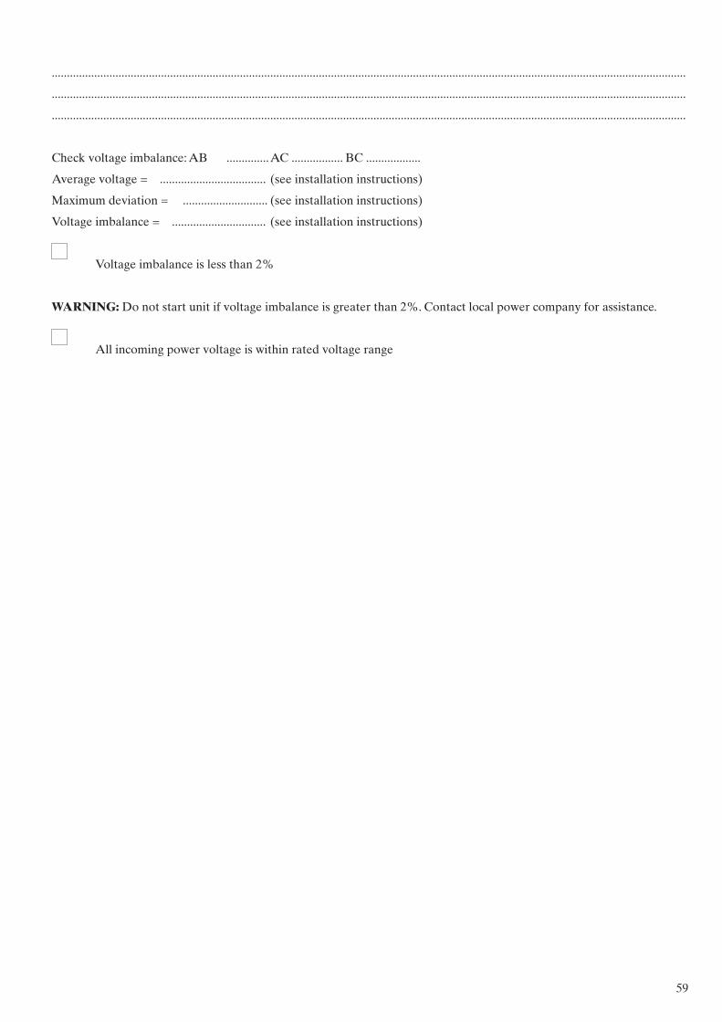
59
.................................................................................................................................................................................................................
.................................................................................................................................................................................................................
.................................................................................................................................................................................................................
Check voltage imbalance: AB .............. AC ................. BC ..................
Average voltage = ................................... (see installation instructions)
Maximum deviation = ............................ (see installation instructions)
Voltage imbalance = ............................... (see installation instructions)
Voltage imbalance is less than 2%
WARNING: Do not start unit if voltage imbalance is greater than 2%. Contact local power company for assistance.
All incoming power voltage is within rated voltage range

60
Carry out the QUICK TEST function (see 50/48 UC-(V)/UP-(V) Touch Pilot Control IOM:
Re-enter the setpoints (see controls section)
To start up the unit
Once all checks have been made, start the unit in the “LOCAL ON” position.
Unit starts and operates properly
Temperatures and pressures
WARNING: Once the machine has been operating at 100% full load for a while and the temperatures and pressures have stabilized, record the following:
Entering air temperature.....................................................................................................................................................................
Leaving air temperature ......................................................................................................................................................................
Ambient temperature...........................................................................................................................................................................
Circuit A suction pressure....................................................................................................................................................................
Circuit B suction pressure ....................................................................................................................................................................
Circuit A discharge pressure................................................................................................................................................................
Circuit B discharge pressure ................................................................................................................................................................
Circuit A suction temperature.............................................................................................................................................................
Circuit B suction temperature..............................................................................................................................................................
Circuit A discharge temperature ........................................................................................................................................................
Circuit B discharge temperature.........................................................................................................................................................
Circuit A liquid line temperature .......................................................................................................................................................
Circuit B liquid line temperature ........................................................................................................................................................
Circuit C suction pressure (THR option)...........................................................................................................................................
Circuit C discharge pressure (THR ption)..........................................................................................................................................
Circuit C suction temperature (THR option)....................................................................................................................................
Circuit C discharge temperature (THR option)................................................................................................................................
Circuit C liquid line temperature (THR option)...............................................................................................................................
ACCESSORIES
.................................................................................................................................................................................................................
.................................................................................................................................................................................................................

61
17 - GAS HEATING SECTION
Gas heater
Size:.............................................................................................. Serial No.: ............... ..................................................................
Pipe size: ............... ...................................................................... Gas type: G ............... ........................................................
Line pressure: .................................................................. mbar
Power input: ................W Flue temp.: ......................... °C
NOX:........................mg/kWh CO ppm: .............................%
NOTE: Complete this start-up list at the time of installation.

62

63

Order No. 13010, 04.2018. Supersedes order No.: New. Manufactured by: Alarko-Carrier, Gebze, Turkey.Manufacturer reserves the right to change any product specification without notice.


![High Pressure Side Channel Pump SHP Exceptional … · High Pressure Side Channel Pump SHP®. Exceptional Process Safety at High Pressures. ... EN 10083 - 1.0501 [1035] A216 Gr WCB](https://img.pdfslide.net/doc/110x75/5b7ba5317f8b9a184a8d06e9/high-pressure-side-channel-pump-shp-exceptional-high-pressure-side-channel-pump.jpg)