Embed Size (px)
Citation preview

50HzSUBMERSIBLE MOTORSAPPLICATION • INSTALLATION • MAINTENANCE

Franklin Electric is committed to provide customers with defect free products through our program of
continuous improvement. Quality shall, in every case, take precedence over quantity.
Commitment To Quality
www.franklin-electric.com

Application - All MotorsStorage ...........................................................................3Frequency of Starts .......................................................3Mounting Position ...........................................................3Transformer Capacity ......................................................4Effects of Torque .............................................................4Engine Driven Generators ...............................................5Use of Check Valves ......................................................5Well Diameters, Casing, Top Feeding, Screens ............. 6Water Temperature and Flow .........................................6Flow Inducer Sleeve ....................................................... 6Head Loss Past Motor ...................................................7Hot Water Applications .............................................. 7-8Drawdown Seals .............................................................9Grounding Control Boxes and Panels ...........................9Grounding Surge Arrestors ............................................9Control Box and Panel Environment ..............................9
Application - Single-Phase Motors3-Wire Control Boxes ..............................................102-Wire Motor Solid State Controls ..........................10Cable Selection - 2-Wire or 3-Wire ..........................11Two Different Cable Sizes ......................................12Single-Phase Motor Specifications .........................13
Application - Three-Phase MotorsCable Selection - 70°C 3 or 6 Lead .............................14Cable Selection - 75°C 3 or 6 Lead ..........................15Three-Phase Motor Specifications ......................... 16-18 Overload Protection .....................................................19Submonitor Three-Phase Protection ............................20Power Factor Correction ..............................................20Three-Phase Starter Diagrams .....................................21Three-Phase Power Unbalance ...................................22Rotation and Current Unbalance ..................................22Submersible Pump Installation Check List (No.3656)Submersible Motor Installation Record (No. 2207)
Submersible Booster Installation Record (No. 3655)Three-Phase Motor Lead Identification .......................23Reduced Voltage Starters ............................................24Inline Booster Pump Systems................................. 24-27Variable Speed Operation .............................................28
Installation - All MotorsSubmersible Motors - Dimensions ...............................29Tightening Lead Connector Jam Nut ...........................30Pump to Motor Coupling .............................................30Shaft Height and Free End Play ...................................30Submersible Leads and Cables ....................................30Splicing Submersible Cables ........................................31Heat Shrink Splicing .....................................................31
Maintenance - All MotorsSystem Troubleshooting ........................................ 32-33Preliminary Tests ..........................................................34Insulation Resistance ...................................................35Resistance of Drop Cable .............................................35
Maintenance - Single-Phase Motors & ControlsIdentification of Cables ................................................36Single-Phase Control Boxes .........................................36Ohmmeter Tests ............................................................37QD Control Box Parts ...................................................38 Integral HP Control Box Parts .......................................38Control Box Wiring Diagrams ................................. 39-40
Maintenance - Electronic ProductsPumptec Troubleshooting ............................................41Pumptec-Plus Troubleshooting During Installation ......42Pumptec-Plus Troubleshooting After Installation .........43CP Water Troubleshooting ............................................44Submonitor Troubleshooting.........................................45Subtrol-Plus Troubleshooting ................................. 46-47
The submersible motor is a reliable, efficient and trouble-free means of powering a pump. Its needs for a long operational life are simple. They are:
1. A suitable operating environment2. An adequate supply of electricity3. An adequate flow of cooling water over the motor4. An appropriate pump load
All considerations of application, installation, and maintenance of submersible motors relate to these four areas. This manual will acquaint you with these needs and assist you if service or maintenance is required.
Application • Installation • Maintenance Manual
Submersible Motors
3
Franklin Electric submersible motors are a water-lubricated design. The fill solution consists of a mixture of de-ionized water and Propylene Glycol (a non-toxic antifreeze). The solution will prevent damage from freezing in temperatures to -40°C; motors should be stored in areas that do not go below this temperature. The solution will partially freeze below -3°C, but no damage occurs. Repeated freezing and thawing should be avoided to prevent possible loss of fill solution.There may be an interchange of fill solution with well water during operation. Care must be taken with motors removed from wells during freezing conditions to prevent damage.
When the storage temperature does not exceed 37°C, storage time should be limited to two years. Where temperatures reach 37° to 54°C, storage time should be limited to one year.Loss of a few drops of liquid will not damage the motor as an excess amount is provided, and the filter check valve will allow lost liquid to be replaced by filtered well water upon installation. If there is reason to believe there has been a considerable amount of leakage, consult the factory for checking procedures.
Storage
Mounting Position
Application - All Motors
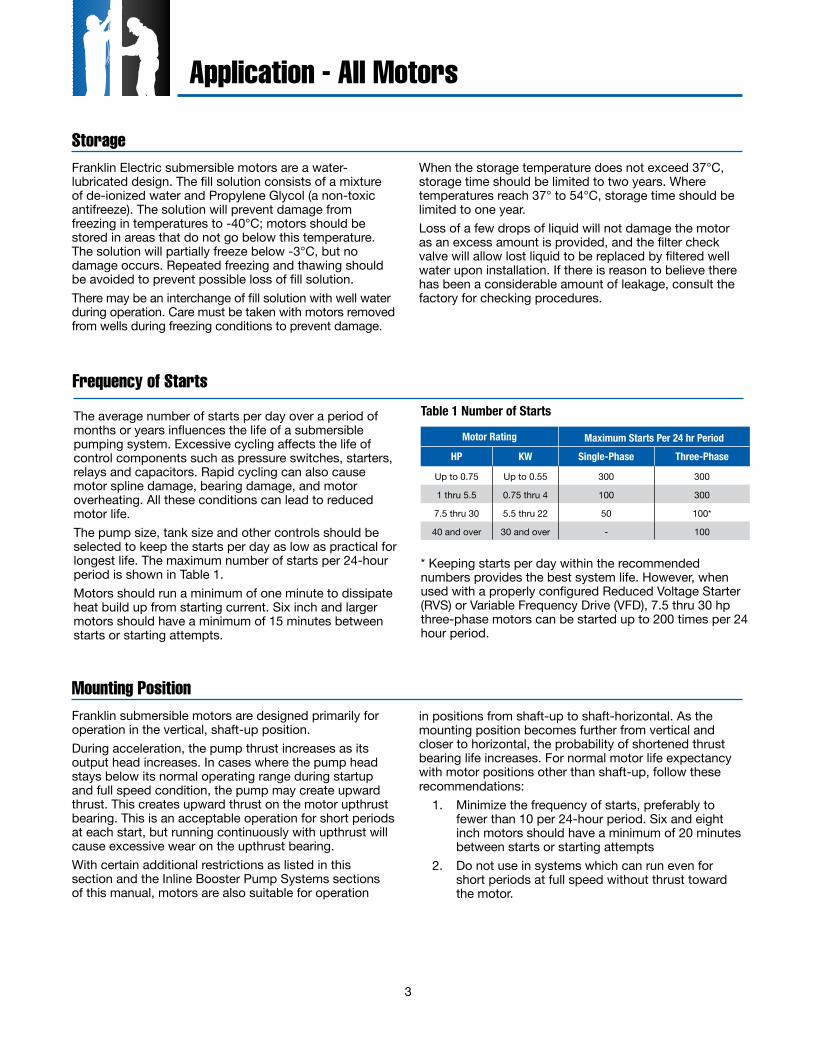
The average number of starts per day over a period of months or years influences the life of a submersible pumping system. Excessive cycling affects the life of control components such as pressure switches, starters, relays and capacitors. Rapid cycling can also cause motor spline damage, bearing damage, and motor overheating. All these conditions can lead to reduced motor life.The pump size, tank size and other controls should be selected to keep the starts per day as low as practical for longest life. The maximum number of starts per 24-hour period is shown in Table 1.Motors should run a minimum of one minute to dissipate heat build up from starting current. Six inch and larger motors should have a minimum of 15 minutes between starts or starting attempts.
Frequency of Starts
Motor Rating Maximum Starts Per 24 hr PeriodHP KW Single-Phase Three-Phase
Up to 0.75 Up to 0.55 300 300
1 thru 5.5 0.75 thru 4 100 300
7.5 thru 30 5.5 thru 22 50 100*
40 and over 30 and over - 100
Table 1 Number of Starts
* Keeping starts per day within the recommended numbers provides the best system life. However, when used with a properly configured Reduced Voltage Starter (RVS) or Variable Frequency Drive (VFD), 7.5 thru 30 hp three-phase motors can be started up to 200 times per 24 hour period.
Franklin submersible motors are designed primarily for operation in the vertical, shaft-up position. During acceleration, the pump thrust increases as its output head increases. In cases where the pump head stays below its normal operating range during startup and full speed condition, the pump may create upward thrust. This creates upward thrust on the motor upthrust bearing. This is an acceptable operation for short periods at each start, but running continuously with upthrust will cause excessive wear on the upthrust bearing.With certain additional restrictions as listed in this section and the Inline Booster Pump Systems sections of this manual, motors are also suitable for operation
in positions from shaft-up to shaft-horizontal. As the mounting position becomes further from vertical and closer to horizontal, the probability of shortened thrust bearing life increases. For normal motor life expectancy with motor positions other than shaft-up, follow these recommendations:
1. Minimize the frequency of starts, preferably to fewer than 10 per 24-hour period. Six and eight inch motors should have a minimum of 20 minutes between starts or starting attempts
2. Do not use in systems which can run even for short periods at full speed without thrust toward the motor.
4
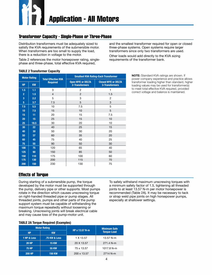
Transformer Capacity - Single-Phase or Three-PhaseDistribution transformers must be adequately sized to satisfy the KVA requirements of the submersible motor. When transformers are too small to supply the load, there is a reduction in voltage to the motor.Table 2 references the motor horsepower rating, single-phase and three-phase, total effective KVA required,
and the smallest transformer required for open or closed three-phase systems. Open systems require larger transformers since only two transformers are used.Other loads would add directly to the KVA sizing requirements of the transformer bank.
Motor Rating Total Effective KVA Required
Smallest KVA Rating-Each Transformer
Open WYE or DELTA 2-Transformers
Closed WYE or DELTA 3-TransformersHP KW
1.5 1.1 3 2 12 1.5 4 2 1.53 2.2 5 3 25 3.7 7.5 5 3
7.5 5.5 10 7.5 510 7.5 15 10 515 11 20 15 7.520 15 25 15 1025 18.5 30 20 1030 22 40 25 1540 30 50 30 2050 37 60 35 2060 45 75 40 2575 55 90 50 30
100 75 120 65 40125 90 150 85 50150 110 175 100 60175 130 200 115 70200 150 230 130 75
TABLE 2 Transformer Capacity
Effects of TorqueDuring starting of a submersible pump, the torque developed by the motor must be supported through the pump, delivery pipe or other supports. Most pumps rotate in the direction which causes unscrewing torque on right-handed threaded pipe or pump stages. All threaded joints, pumps and other parts of the pump support system must be capable of withstanding the maximum torque repeatedly without loosening or breaking. Unscrewing joints will break electrical cable and may cause loss of the pump-motor unit.
To safely withstand maximum unscrewing torques with a minimum safety factor of 1.5, tightening all threaded joints to at least 13.57 N-m per motor horsepower is recommended (Table 2A). It may be necessary to tack or strap weld pipe joints on high horsepower pumps, especially at shallower settings.
NOTE: Standard KVA ratings are shown. If power company experience and practice allows transformer loading higher than standard, higher loading values may be used for transformer(s) to meet total effective KVA required, provided correct voltage and balance is maintained.
Motor RatingHP x 13.57 N-m Minimum Safe
Torque-Load HP KW
1 HP & Less .75 KW & Less 1 X 13.57 13.57 N-m
20 HP 15 KW 20 X 13.57 271.4 N-m
75 HP 55 KW 75 x 13.57 1017.8 N-m
200 HP 150 KW 200 x 13.57 2714 N-m
TABLE 2A Torque Required (Examples)
Application - All Motors
5
Engine Driven GeneratorsRefer to generator manufacturer’s recommendations and locked rotor amps listed on page 13 (single-phase) and pages 16-18 (three-phase).
Use of Check Valves
Application - All Motors
It is recommended that one or more check valves always be used in submersible pump installations. If the pump does not have a built-in check valve, a line check valve should be installed in the discharge line within 7.6 m (25 feet) of the pump and below the draw down level of the water supply. For deeper settings, check valves should be installed per the manufacturer’s recommendations. More than one check valve may be required, but more than the recommended number of check valves should not be used.Swing type check valves are not acceptable and should never be used with submersible motors/pumps. Swing type check valves have a slower reaction time which can cause water hammer (see next page). Internal pump check valves or spring loaded check valves close quickly and help eliminate water hammer.Check valves are used to hold pressure in the system when the pump stops. They also prevent backspin, water hammer and upthrust. Any of these can lead to early pump or motor failure.NOTE: Only positive sealing check valves should be used in submersible installations. Although drilling the check valves or using drain-back check valves may prevent back spinning, they create upthrust and water hammer problems.
A. Backspin - With no check valve or a failed check valve, the water in the drop pipe and the water in the system can flow down the discharge pipe when the motor stops. This can cause the pump to rotate in a reverse direction. If the motor is started while it is backspinning, an excessive force is placed across the pump-motor assembly that can cause impeller damage, motor or pump shaft breakage, excessive bearing wear, etc.
B. Upthrust - With no check valve, a leaking check valve, or drilled check valve, the unit starts under a zero head condition. This causes an uplifting or upthrust on the impeller-shaft assembly in the pump. This upward movement carries across the pump-motor coupling and creates an upthrust condition in the motor. Repeated upthrust can cause premature failure of both the pump and the motor.
C. Water Hammer - If the lowest check valve is more than 9.1 m (30 feet) above the standing (lowest static) water level, or a lower check valve leaks and the check valve above holds, a vacuum is created in the discharge piping. On the next pump start, water moving at very high velocity fills the void and strikes the closed check valve and the stationary water in the pipe above it, causing a hydraulic shock. This shock can split pipes, break joints and damage the pump and/or motor. Water hammer can often be heard or felt. When discovered, the system should be shut down and the pump installer contacted to correct the problem.
6
Application - All Motors
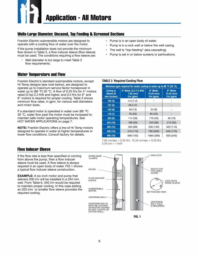
Wells-Large Diameter, Uncased, Top Feeding & Screened SectionsFranklin Electric submersible motors are designed to operate with a cooling flow of water over the motor.If the pump installation does not provide the minimum flow shown in Table 3, a flow inducer sleeve (flow sleeve) must be used. The conditions requiring a flow sleeve are:
• Well diameter is too large to meet Table 3 flow requirements.
• Pump is in an open body of water.• Pump is in a rock well or below the well casing.• The well is “top-feeding” (aka cascading).• Pump is set in or below screens or perforations.
Water Temperature and FlowTABLE 3 Required Cooling Flow
Flow Inducer SleeveIf the flow rate is less than specified or coming from above the pump, then a flow inducer sleeve must be used. A flow sleeve is always required in an open body of water. FIG 1 shows a typical flow inducer sleeve construction.
EXAMPLE: A six-inch motor and pump that delivers 200 l/m will be installed in a 254 mm well. From Table 6, 340 l/m would be required to maintain proper cooling. In this case adding an 203 mm or smaller flow sleeve provides the required cooling.
WORM GEARCLAMPS
INTAKE
FLOW INDUCERSLEEVE
SUBMERSIBLEMOTOR
CENTERING BOL T
LOCK NUTS INSIDE SLEEVE
CENTERINGBOLT HOLE(3 REQUIRED)
BOTTOM END VIEW
NOTCH OUTFOR CABLEGUARD
SAW CUTS
CENTERING BOLTSMUST BE LOCATEDON MOTOR CASTING.DO NOT LOCATE ONSTATOR SHELL.
FIG. 1
7.62 cm/sec = 0.25 ft/s 15.24 cm/sec = 0.50 ft/s 2.54 cm = 1 inch
Minimum gpm required for motor cooling in water up to 86 °F (30 °C).Casing orSleeve ID
mm (inches)
4" Motor (2.2-7.5 KW) 7.62 cm/sl/m (gpm)
6" Motor15.24 cm/sl/m (gpm)
8" Motor15.24 cm/sl/m (gpm)
102 (4) 4.5 (1.2) - -127 (5) 26.5 (7) - -152 (6) 49 (13) 34 (9) -178 (7) 76 (20) 95 (25) -203 (8) 114 (30) 170 (45) 40 (10)
254 (10) 189 (50) 340 (90) 210 (55)305 (12) 303 (80) 530 (140) 420 (110)356 (14) 416 (110) 760 (200) 645 (170)406 (16) 568 (150) 1060 (280) 930 (245)
Franklin Electric’s standard submersible motors, except Hi-Temp designs (see note below), are designed to operate up to maximum service factor horsepower in water up to (86 °F) 30 °C. A flow of 0.25 ft/s for 4" motors rated (3 hp) 2.2 KW and higher, and 0.5 ft/s for 6" and 8" motors is required for proper cooling. Table 3 shows minimum flow rates, in gpm, for various well diameters and motor sizes.
If a standard motor is operated in water over (86 °F) 30 °C, water flow past the motor must be increased to maintain safe motor operating temperatures. See HOT WATER APPLICATIONS on page 7.
NOTE: Franklin Electric offers a line of Hi-Temp motors designed to operate in water at higher temperatures or lower flow conditions. Consult factory for details.
7
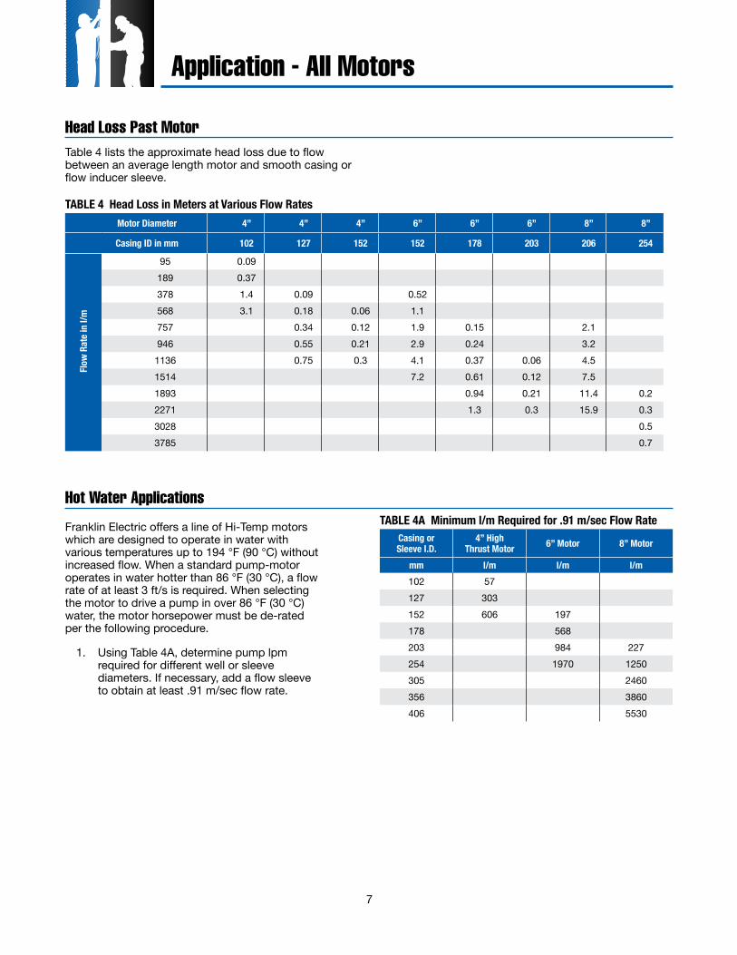
Table 4 lists the approximate head loss due to flow between an average length motor and smooth casing or flow inducer sleeve.
Motor Diameter 4” 4” 4” 6” 6” 6” 8” 8”
Casing ID in mm 102 127 152 152 178 203 206 254
Flow
Rate
in l/
m
95 0.09189 0.37378 1.4 0.09 0.52568 3.1 0.18 0.06 1.1757 0.34 0.12 1.9 0.15 2.1946 0.55 0.21 2.9 0.24 3.21136 0.75 0.3 4.1 0.37 0.06 4.51514 7.2 0.61 0.12 7.51893 0.94 0.21 11.4 0.22271 1.3 0.3 15.9 0.33028 0.53785 0.7
TABLE 4 Head Loss in Meters at Various Flow Rates
Hot Water Applications
Casing orSleeve I.D.
4” High Thrust Motor 6” Motor 8” Motor
mm l/m l/m l/m102 57127 303152 606 197178 568203 984 227254 1970 1250305 2460356 3860406 5530
TABLE 4A Minimum l/m Required for .91 m/sec Flow Rate
Application - All Motors
Franklin Electric offers a line of Hi-Temp motors which are designed to operate in water with various temperatures up to 194 °F (90 °C) without increased flow. When a standard pump-motor operates in water hotter than 86 °F (30 °C), a flow rate of at least 3 ft/s is required. When selecting the motor to drive a pump in over 86 °F (30 °C) water, the motor horsepower must be de-rated per the following procedure.
1. Using Table 4A, determine pump lpm required for different well or sleeve diameters. If necessary, add a flow sleeve to obtain at least .91 m/sec flow rate.
Head Loss Past Motor

8
00 18.9 37.9 56.8 75.7 94.6 113.6 132.5 155 174.4 193.8
Liters Per Minute
Bra
ke K
W (H
orse
pow
er) 4.5 (6)
3.7 (5)
3.0 (4)
2.2 (3)
1.5 (2)
.75 (1)
A
B
C
EXAMPLE2. Determine pump KW (HP)
required from the pump manufacturer’s curve.
FIG. 2 MANUFACTURER’S PUMP CURVE
MaximumWater Temperature
1/3 - 5 HP.25 - 3.7 KW
7 1/2 - 30 HP5.5 - 22 KW
Over 30HPOver 22 KW
60°C 1.25 1.62 2.0055°C 1.11 1.32 1.6250°C 1.00 1.14 1.3245°C 1.00 1.00 1.1440°C 1.00 1.00 1.0035°C 1.00 1.00 1.00
3. Multiply the pump KW (HP) required by the heat factor multiplier from Table 5.
Application - All Motors
TABLE 5 Heat Factor Multiplier at .91 m/sec Flow Rate
4. Select a rated KW (HP)motor on table 5A whose Service Factor Horsepower is at least the value calculated in Item 3.
TABLE 5A Service Factor HorsepowerHP kW SFHP HP kW SFHP HP kW SFHP HP kW SFHP
1/3 0.25 0.58 3 2.2 3.45 25 18.5 28.75 100 75 115.00
1/2 0.37 0.80 5 3.7 5.75 30 22.0 34.50 125 93 143.75
3/4 0.55 1.12 7.5 5.5 8.62 40 30.0 46.00 150 110 172.50
1 0.75 1.40 10 7.5 11.50 50 37.0 57.50 175 130 201.25
1.5 1.10 1.95 15 11.0 17.25 60 45.0 69.00 200 150 230.00
2 1.50 2.50 20 15.0 23.00 75 55.0 86.25
Hot Water Applications - Example
EXAMPLE: A 6” pump end requiring 29.1 KW (39 HP) input will pump 51°C water in an 203 mm well at a delivery rate of 530 l/m. From table 4A, a 152 mm flow sleeve will be required to increase the flow rate to at least .91 m/sec.Using table 5, the 1.62 heat factor multiplier is selected because the KW (HP) required is over 22 KW (30 HP) and
water temperature is above 50°C. Multiply 29.1 KW x 1.62 (multiplier), which equals 47.1 KW (63.2 HP). This is the minimum rated full load horsepower usable at 21.9 KW (39 HP) in 51°C. Using table 5A, select a motor with a rated service factor above 47.1 KW (63.2 HP). A 45 KW (60 HP) motor has a service factor kilowatt of 51.4 (69 HP), so a 45 kw (60 HP) motor may be used.
9
Drawdown SealsAllowable motor temperature is based on atmospheric pressure or higher surrounding the motor. “Drawdown seals,” which seal the well to the pump above it’s intake
to maximize delivery, are not recommended, since the suction created can be lower than atmospheric pressure.
Grounding Control Boxes and PanelsThe United States National Electrical Code requires that the control box or panel-grounding terminal always be connected to supply ground. If the circuit has no grounding conductor and no metal conduit from the box to supply panel, use a wire at least as large as line conductors and connect as required by the National Electrical Code, from the grounding terminal to the electrical supply ground.
Connect earth grounds to control boxes and panels per local and national codes or regulations.
Grounding Surge ArrestorsAn above ground surge arrestor must be grounded, metal to metal, all the way to the lowest draw down water strata for the surge arrestor to be effective. GROUNDING THE ARRESTOR TO THE SUPPLY GROUND OR TO A DRIVEN GROUND ROD PROVIDES LITTLE OR NO PROTECTION FOR THE MOTOR.
Control Box and Panel Environment
Equipment Grounding
The primary purpose of grounding the metal drop pipe and/or metal well casing in an installation is safety. It is done to limit the voltage between nonelectrical (exposed metal) parts of the system and ground, thus minimizing dangerous shock hazards. Using wire at least the size of the motor cable wires provides adequate current-carrying capability for any ground fault that might occur. It also provides a low resistance path to ground, ensuring that the current to ground will be large enough to trip any overcurrent device designed to detect faults (such as a ground fault circuit interrupter, or GFCI). Normally, the ground wire to the motor would provide the
primary path back to the power supply ground for any ground fault. There are conditions, however, where the ground wire connection could become compromised. One such example would be the case where the water in the well is abnormally corrosive or aggressive. In this example, a grounded metal drop pipe or casing would then become the primary path to ground. However, the many installations that now use plastic drop pipes and/or casings require further steps to be taken for safety purposes, so that the water column itself does not become the conductive path to ground.When an installation has abnormally corrosive water AND the drop pipe or casing is plastic, Franklin Electric recommends the use of a GFCI with a 10 mA set-point. In this case, the motor ground wire should be routed through the current-sensing device along with the motor power leads. Wired this way, the GFCI will trip only when a ground fault has occurred AND the motor ground wire is no longer functional.
WARNING: Serious or fatal electrical shock may result from failure to connect the motor, control enclosures, metal plumbing and all other metal near the motor or cable to the power supply ground terminal using wire no smaller than motor cable wires.
WARNING: Failure to ground the control frame can result in a serious or fatal electrical shock.
Application - All Motors
Franklin Electric control boxes, Pumptec products and three-phase panels meet UL requirements for NEMA Type 3R enclosures. They are suitable for indoor and outdoor applications within temperatures of -10 °C (+14 °F) to 50 °C (122 °F). Operating control boxes below +14 °F can cause reduced starting torque and loss of overload protection when overloads are located in control boxes. Control boxes, Pumptec products and three-phase panels should never be mounted in direct sunlight or
high temperature locations. This will cause shortened capacitor life (where applicable) and unnecessary tripping of overload protectors. A ventilated enclosure painted white to reflect heat is recommended for an outdoor, high temperature location.A damp well pit, or other humid location, accelerates component failure from corrosion.Control boxes with voltage relays are designed for vertical upright mounting only. Mounting in other positions will affect the operation of the relay.
10
3-Wire Control BoxesSingle-phase three-wire submersible motors require the use of control boxes. Operation of motors without control boxes or with incorrect boxes can result in motor failure and voids warranty.Control boxes contain starting capacitors, a starting relay, overload protectors, and, in some sizes, running capacitors.Potential (Voltage) Relays Potential relays have normally closed contacts. When power is applied, both start and main motor windings are energized, and the motor starts. At this instant, the voltage across the start winding is relatively low and not enough to open the contacts of the relay.
As the motor accelerates, the increasing voltage across the start winding (and the relay coil) opens the relay contacts. This opens the starting circuit and the motor continues to run on the main winding alone, or the main plus run capacitor circuit. After the motor is started the relay contacts remain open.
2-Wire Motor Solid State ControlsBIAC Switch OperationWhen power is applied the bi-metal switch contacts are closed so the triac is conducting and energizes the start winding. As RPM increases, the voltage in the sensor coil generates heat in the bi-metal strip, causing the bi-metal strip to bend and open the switch circuit. This removes the starting winding and the motor continues to run on the main winding alone.Approximately 5 seconds after power is removed from the motor, the bi-metal strip cools sufficiently to return to its closed position and the motor is ready for the next start cycle. If, during operation, the motor speed drops, the lowered voltage in the sensor coil allows the bi-metal contacts to close, and bring the motor back to operating speed.Rapid CyclingThe BIAC starting switch will reset within approximately 5 seconds after the motor is stopped. If an attempt is made to restart the motor before the starting switch has reset, the motor may not start; however, there will be
current in the main winding until the overload protector interrupts the circuit. The time for the protector to reset is longer than the reset of the starting switch. Therefore, the start switch will have closed and the motor will operate. A waterlogged tank will cause fast cycling. When a waterlogged condition does occur, the user will be alerted to the problem during the off time (overload reset time) since the pressure will drop drastically. When the waterlogged tank condition is detected the condition should be corrected to prevent nuisance tripping of the overload protector.Bound Pump (Sandlocked)When the motor is not free to turn, as with a sandlocked pump, the BIAC switch creates a “reverse impact torque” in the motor in either direction. When the sand is dislodged, the motor will start and operate in the correct direction.
CAUTION: Restarting the motor within 5 seconds after power is removed may cause the motor overload to trip.
Application - Single-Phase Motors
CAUTION: The control box and motor are two pieces of one assembly. Be certain that the control box and motor hp and voltage match. Since a motor is designed to operate with a control box from the same manufacturer, we can promise warranty coverage only when a Franklin control box is used with a Franklin motor.
11
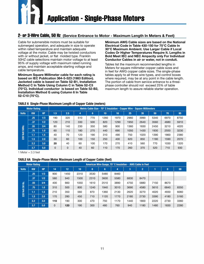
2- or 3-Wire Cable, 50 Hz (Service Entrance to Motor - Maximum Length In Meters & Feet)Cable for submersible motors must be suitable for submerged operation, and adequate in size to operate within rated temperature and maintain adequate voltage at the motor. Cable may be twisted conductors with or without jacket, or flat molded type. Franklin 50HZ cable selections maintain motor voltage to at least 95% of supply voltage with maximum rated running amps, and maintain acceptable starting voltage and cable temperature.Minimum Square Millimeter cable for each rating is based on IEC Publication 364-5-523 (1983 Edition). Jacketed cable is based on Table 52-B1, Installation Method C In Table Using Column C in Table 52-C3 (70°C). Individual conductor is based on Table 52-B2, Installation Method G using Column 6 In Table 52-C10 (70°C).
Minimum AWG Cable sizes are based on the National Electrical Code in Table 430-150 for 75°C Cable In 30°C Maximum Ambient. Use Larger Cable if Local Codes Or Higher Temperatures Require It. Lengths in Bold Meet IEC and NEC Ampacity only For Individual Conductor Cables in air or water, not in conduit.Tables list the maximum recommended lengths in Meters for square millimeter copper cable sizes and in feet for AWG copper cable sizes. The single-phase tables apply to all three wire types, and control boxes where required, may be at any point in the cable length. The portion of cable from service entrance to a three-phase controller should not exceed 25% of table maximum length to assure reliable starter operation.
Motor Rating Metric Cable Size - 70° C Insulation - Copper Wire - Square Millimeters Volts KW HP 1.5 2.5 4 6 10 16 25 35 50 70 95
220 V
olt 5
0Hz.
.25 1/3 190 320 510 770 1260 1970 2960 3990 5340 6970 8750
.37 1/2 120 210 330 500 820 1290 1950 2640 3560 4680 5910
.55 3/4 80 140 230 350 580 900 1360 1830 2450 3210 4020
.75 1.0 60 110 180 270 440 690 1050 1430 1930 2550 32301.1 1.5 40 70 120 190 310 490 750 1020 1390 1860 23801.5 2.0 30 60 100 150 250 400 620 850 1180 1590 20702.2 3.0 20 40 60 100 170 270 410 560 770 1030 13203.7 5.0 0 0 40 60 110 170 260 370 520 710 930
Motor Rating American Wire Guage, 75° C Insulation - AWG Cable in FeetVolts KW HP 14 12 10 8 6 4 3 2 1 0 00
220 V
olt 5
0 Hz
.
.25 1/3 900 1450 2310 3530 5480 8460
.37 1/2 580 940 1500 2310 3600 5580 6830 8470
.55 3/4 400 660 1050 1610 2510 3890 4750 5880 7150 8670
.75 1.0 310 500 800 1240 1940 3010 3690 4580 5610 6840 83501.1 1.5 210 350 560 870 1360 2130 2620 3270 4020 4930 60601.5 2.0 170 280 450 710 1120 1770 2180 2730 3390 4180 51602.2 3.0 110 190 300 470 750 1170 1440 1800 2220 2730 33603.7 5.0 0 120 190 300 480 760 940 1180 1480 1830 2280
TABLE 6 Single-Phase Maximum Length of Copper Cable (meters)
TABLE 6A Single-Phase Motor Maximum Length of Copper Cable (feet)
1 Meter = 3.3 feet
Application - Single-Phase Motors
12
Application - Single-Phase Motors
Two different cable sizes can be used.
2.2kW, 230 VSingle-Phase Motor
50M
10m
m2
(29.
4% o
f allo
wab
le c
able
)
40M 4mm2
(66.6% of allowable cable)
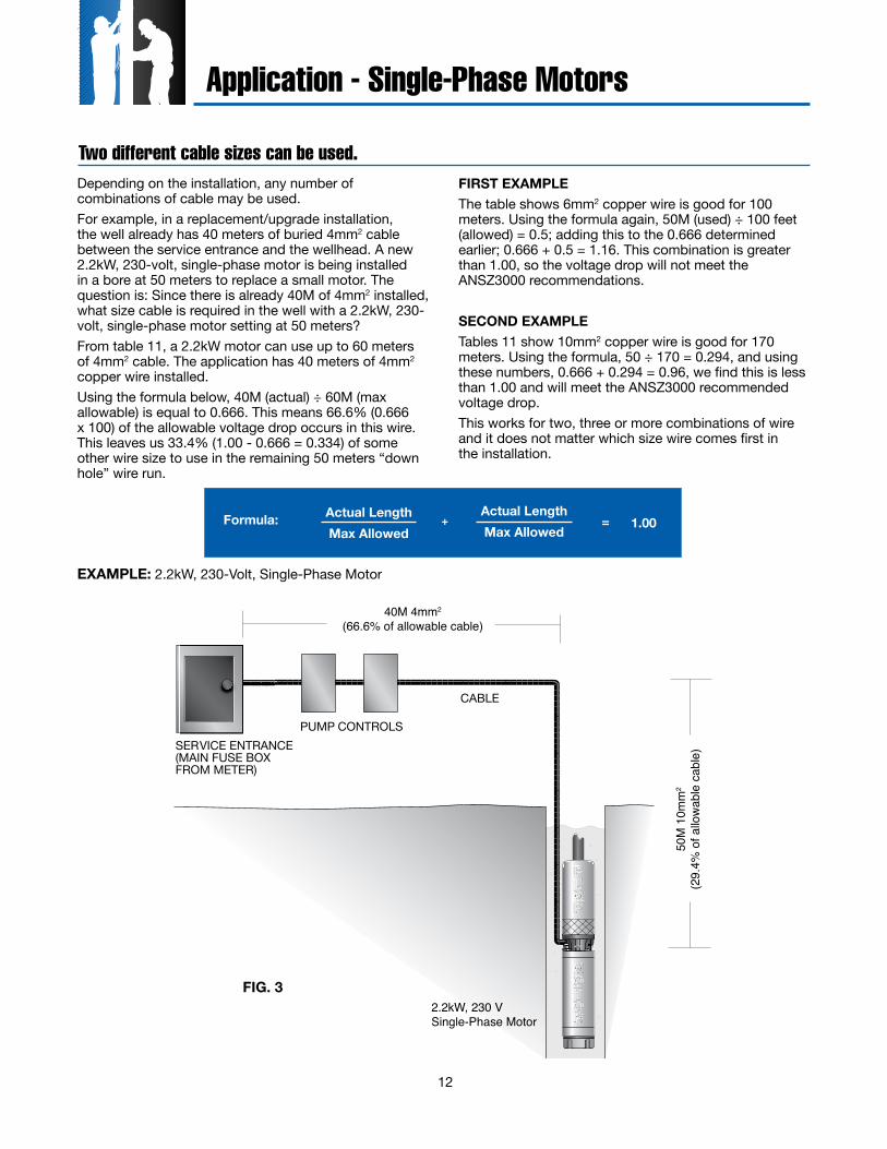
Depending on the installation, any number of combinations of cable may be used.For example, in a replacement/upgrade installation, the well already has 40 meters of buried 4mm2 cable between the service entrance and the wellhead. A new 2.2kW, 230-volt, single-phase motor is being installed in a bore at 50 meters to replace a small motor. The question is: Since there is already 40M of 4mm2 installed, what size cable is required in the well with a 2.2kW, 230-volt, single-phase motor setting at 50 meters?From table 11, a 2.2kW motor can use up to 60 meters of 4mm2 cable. The application has 40 meters of 4mm2 copper wire installed.Using the formula below, 40M (actual) ÷ 60M (max allowable) is equal to 0.666. This means 66.6% (0.666 x 100) of the allowable voltage drop occurs in this wire. This leaves us 33.4% (1.00 - 0.666 = 0.334) of some other wire size to use in the remaining 50 meters “down hole” wire run.
FIRST EXAMPLEThe table shows 6mm2 copper wire is good for 100 meters. Using the formula again, 50M (used) ÷ 100 feet (allowed) = 0.5; adding this to the 0.666 determined earlier; 0.666 + 0.5 = 1.16. This combination is greater than 1.00, so the voltage drop will not meet the ANSZ3000 recommendations.
SECOND EXAMPLETables 11 show 10mm2 copper wire is good for 170 meters. Using the formula, 50 ÷ 170 = 0.294, and using these numbers, 0.666 + 0.294 = 0.96, we find this is less than 1.00 and will meet the ANSZ3000 recommended voltage drop.This works for two, three or more combinations of wire and it does not matter which size wire comes first in the installation.
EXAMPLE: 2.2kW, 230-Volt, Single-Phase Motor
FIG. 3
Formula: + = 1.00Actual LengthMax Allowed
Actual LengthMax Allowed
13
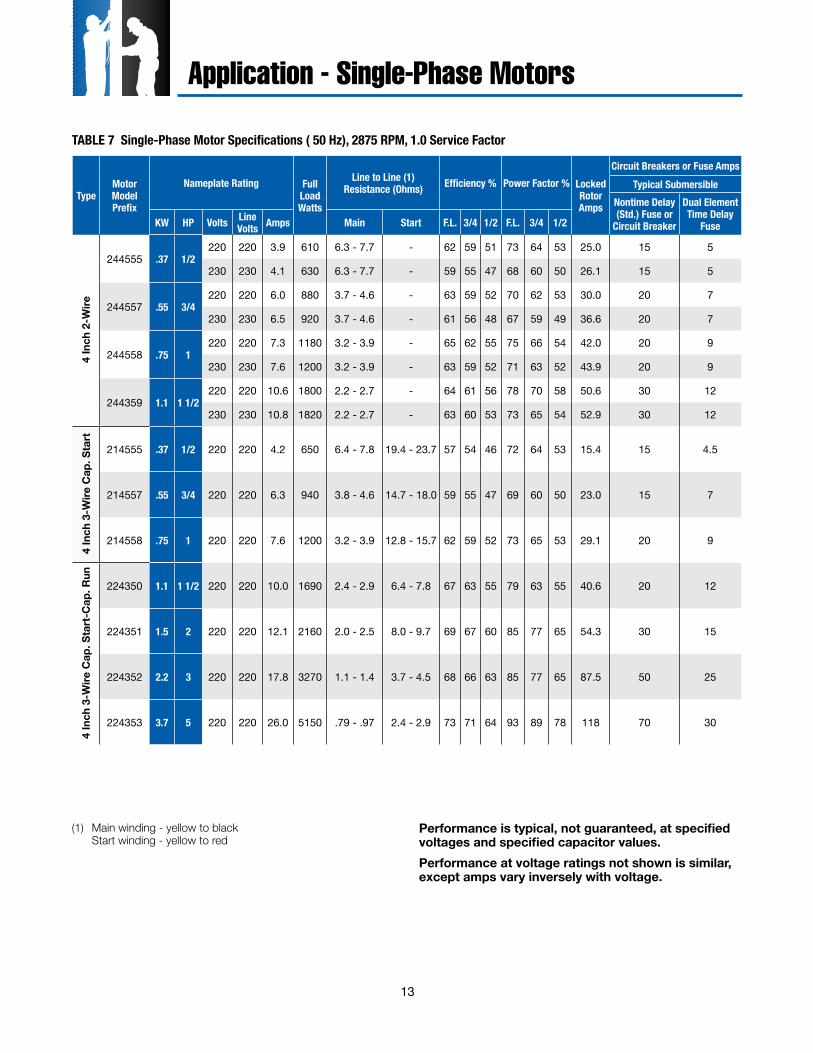
TABLE 7 Single-Phase Motor Specifications ( 50 Hz), 2875 RPM, 1.0 Service Factor
Application - Single-Phase Motors
(1) Main winding - yellow to black Start winding - yellow to red
Performance is typical, not guaranteed, at specified voltages and specified capacitor values.Performance at voltage ratings not shown is similar, except amps vary inversely with voltage.
TypeMotor Model Prefix
Nameplate Rating Full Load Watts
Line to Line (1) Resistance (Ohms) Efficiency % Power Factor % Locked
Rotor Amps
Circuit Breakers or Fuse AmpsTypical Submersible
Nontime Delay (Std.) Fuse or
Circuit Breaker
Dual Element Time Delay
FuseKW HP Volts Line Volts Amps Main Start F.L. 3/4 1/2 F.L. 3/4 1/2
4 In
ch 2
-Wire
244555 .37 1/2220 220 3.9 610 6.3 - 7.7 - 62 59 51 73 64 53 25.0 15 5
230 230 4.1 630 6.3 - 7.7 - 59 55 47 68 60 50 26.1 15 5
244557 .55 3/4220 220 6.0 880 3.7 - 4.6 - 63 59 52 70 62 53 30.0 20 7
230 230 6.5 920 3.7 - 4.6 - 61 56 48 67 59 49 36.6 20 7
244558 .75 1220 220 7.3 1180 3.2 - 3.9 - 65 62 55 75 66 54 42.0 20 9
230 230 7.6 1200 3.2 - 3.9 - 63 59 52 71 63 52 43.9 20 9
244359 1.1 1 1/2220 220 10.6 1800 2.2 - 2.7 - 64 61 56 78 70 58 50.6 30 12
230 230 10.8 1820 2.2 - 2.7 - 63 60 53 73 65 54 52.9 30 12
4 In
ch 3
-Wire
Cap
. Sta
rt
214555 .37 1/2 220 220 4.2 650 6.4 - 7.8 19.4 - 23.7 57 54 46 72 64 53 15.4 15 4.5
214557 .55 3/4 220 220 6.3 940 3.8 - 4.6 14.7 - 18.0 59 55 47 69 60 50 23.0 15 7
214558 .75 1 220 220 7.6 1200 3.2 - 3.9 12.8 - 15.7 62 59 52 73 65 53 29.1 20 9
4 In
ch 3
-Wire
Cap
. Sta
rt-C
ap. R
un
224350 1.1 1 1/2 220 220 10.0 1690 2.4 - 2.9 6.4 - 7.8 67 63 55 79 63 55 40.6 20 12
224351 1.5 2 220 220 12.1 2160 2.0 - 2.5 8.0 - 9.7 69 67 60 85 77 65 54.3 30 15
224352 2.2 3 220 220 17.8 3270 1.1 - 1.4 3.7 - 4.5 68 66 63 85 77 65 87.5 50 25
224353 3.7 5 220 220 26.0 5150 .79 - .97 2.4 - 2.9 73 71 64 93 89 78 118 70 30
14
Application - Three-Phase Motors
Motor Rating Metric Cable Size, Square Millimeters, Copper Wire - 70°C Rated InsulationVolts KW HP 1.5 2.5 4 6 10 16 25 35 50 70 95 120 150 185 240 300 400
220v
50H
z 3Ø
3
- Lea
d(2
30V
may
use
110
% o
f tab
le)
(240
V m
ay u
se 1
19%
of t
able)
.37 1/2 300 510 820 1230 2010 3160 4810 6540 8890
.55 3/4 200 350 550 830 1370 2150 3280 4460 6060 8060
.75 1 160 270 430 650 1070 1680 2550 3470 4710 6250 7970 95101.1 1 1/2 110 190 300 450 750 1170 1790 2430 3310 4400 5620 6700 7790 89701.5 2 80 140 230 340 570 900 1380 1880 2570 3430 4410 5290 6180 7150 8470 96702.2 3 50 90 150 230 380 600 920 1270 1740 2330 3000 3610 4230 4910 5840 6700 77903 4 40 70 110 170 280 440 670 920 1270 1700 2180 2630 3080 3570 4240 4850 5630
3.7 5 30 50 90 130 220 360 550 750 1030 1390 1790 2150 2520 2930 3480 4000 46404 5 1/2 30 50 80 120 200 320 490 670 920 1240 1590 1910 2240 2590 3070 3520 4070
5.5 7 1/2 0 30 60 90 150 240 380 520 710 960 1240 1490 1750 2040 2430 2790 32507.5 10 0 0 40 60 110 170 270 370 500 680 870 1050 1230 1420 1690 1930 223011 15 0 0 0 40 80 120 190 270 370 500 650 790 930 1080 1290 1490 174015 20 0 0 0 0 60 90 150 200 280 380 500 610 720 840 1010 1170 1370
18.5 25 0 0 0 0 0 70 110 160 220 300 390 480 570 660 800 920 109022 30 0 0 0 0 0 60 100 130 190 260 330 400 480 560 670 780 910
380v
50H
z 3Ø
3
- Lea
d(4
00V
may
use
110
% o
f tab
le)
(415
V m
ay u
se 1
19%
of t
able)
.37 1/2 930 1550 2460 3670 6030 9460
.55 3/4 630 1050 1670 2500 4100 6440 9790
.75 1 490 820 1300 1950 3200 5020 76201.1 1 1/2 340 570 910 1360 2240 3520 5350 7280 98901.5 2 260 430 700 1040 1720 2700 4120 5630 76902.2 3 170 290 460 700 1150 1810 2770 3790 5190 6950 89503 4 120 210 340 510 840 1330 2030 2770 3790 5070 6530 7840 9190
3.7 5 100 170 270 410 680 1080 1650 2260 3090 4140 5340 6420 7540 87504 5 1/2 90 150 250 370 610 970 1480 2020 2770 3700 4750 5710 6680 7740 9180
5.5 7 1/2 70 110 190 280 470 740 1140 1560 2140 2870 3700 4460 5240 6090 7250 8330 97007.5 10 50 80 130 200 330 530 810 1110 1510 2030 2610 3130 3670 4250 5040 5770 668011 15 0 60 90 140 240 380 590 810 1120 1510 1950 2350 2770 3230 3860 4450 520015 20 0 0 70 110 180 290 450 620 860 1160 1500 1820 2150 2520 3020 3490 4110
18.5 25 0 0 0 80 140 230 350 490 680 910 1190 1440 1700 1990 2390 2770 326022 30 0 0 0 0 120 190 300 410 570 770 1000 1210 1440 1680 2010 2330 274030 40 0 0 0 0 0 140 220 310 420 570 740 900 1060 1230 1470 1700 199037 50 0 0 0 0 0 110 180 240 340 460 590 710 840 980 1170 1350 158045 60 0 0 0 0 0 0 150 200 280 380 490 600 700 820 980 1130 133055 75 0 0 0 0 0 0 120 170 240 330 420 510 610 710 860 990 117075 100 0 0 0 0 0 0 0 0 180 240 320 390 460 530 640 740 88090 125 0 0 0 0 0 0 0 0 0 190 240 290 350 400 480 550 650
110 150 0 0 0 0 0 0 0 0 0 0 210 250 290 340 410 470 550130 175 0 0 0 0 0 0 0 0 0 0 180 220 260 300 360 420 500150 200 0 0 0 0 0 0 0 0 0 0 0 190 230 270 320 370 440
6 - Lead Wye - DeltaMotor Rating Metric Cable Size, Square Millimeters, Copper Wire - 70°C Rated Insulation
Volts KW HP 1.5 2.5 4 6 10 16 25 35 50 70 95 120 150 185 240 300 400
220v
50H
z 3Ø
6 -
Lead
(230
V =
110%
) (2
40V
= 11
9%) 3.7 5 40 70 130 190 330 540 820 1120 1540 2080 2680 3220 3780 4390 5220 6000 6960
5.5 7 1/2 30 40 90 130 220 360 570 780 1060 1440 1860 2230 2620 3060 3640 4180 48707.5 10 10 30 60 90 160 250 400 550 750 1020 1300 1570 1840 2130 2530 2890 334011 15 0 30 40 60 120 180 280 400 550 750 970 1180 1390 1620 1930 2230 261015 20 0 0 30 40 90 130 220 300 420 570 750 910 1080 1260 1510 1750 2050
18.5 25 0 0 0 30 60 100 160 240 330 450 580 720 850 990 1200 1380 163022 30 0 0 0 0 60 90 150 190 280 390 490 600 720 840 1000 1170 1360
380v
50H
z 3Ø
6 -
Lead
(4
00V
may
use
110
% o
f tab
le)
(415
V m
ay u
se 1
19%
of t
able)
3.7 5 150 250 400 610 1020 1620 2470 3390 4630 6210 8010 96305.5 7 1/2 100 160 280 420 700 1110 1710 2340 3210 4300 5550 6690 7860 91307.5 10 70 120 190 300 490 790 1210 1660 2260 3040 3910 4690 5500 6370 7560 865011 15 40 90 130 210 360 570 880 1210 1680 2260 2920 3520 4150 4840 5790 6670 780015 20 30 60 100 160 270 430 670 930 1290 1740 2250 2730 3220 3780 4530 5230 6160
18.5 25 0 40 70 120 210 340 520 730 1020 1360 1780 2160 2550 2980 3580 4150 489022 30 0 0 70 100 180 280 450 610 850 1150 1500 1810 2160 2520 3010 3490 411030 40 0 0 0 70 130 210 330 460 630 850 1110 1350 1590 1840 2200 2550 298037 50 0 0 0 0 100 160 270 360 510 690 880 1060 1260 1470 1750 2020 237045 60 0 0 0 0 90 130 220 300 420 570 730 900 1050 1230 1470 1690 199055 75 0 0 0 0 0 120 180 250 360 490 630 760 910 1060 1290 1480 175075 100 0 0 0 0 0 90 130 190 270 360 480 580 690 790 960 1110 132090 125 0 0 0 0 0 0 100 150 210 280 360 430 520 600 720 820 970
110 150 0 0 0 0 0 0 0 120 180 240 310 370 430 510 610 700 820130 175 0 0 0 0 0 0 0 0 150 210 270 330 390 450 540 630 750150 200 0 0 0 0 0 0 0 0 130 180 240 280 340 400 480 550 660
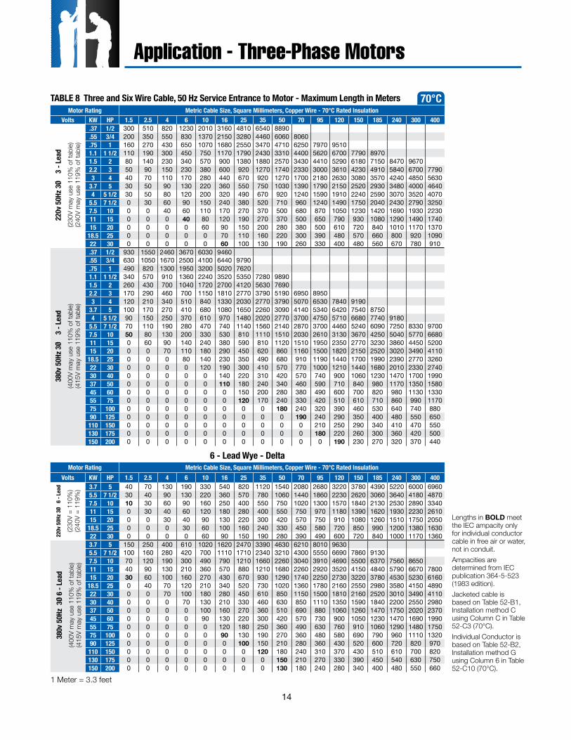
Lengths in BOLD meet the IEC ampacity only for individual conductor cable in free air or water, not in conduit. Ampacities are determined from IEC publication 364-5-523 (1983 edition).Jacketed cable is based on Table 52-B1, Installation method C using Column C in Table 52-C3 (70°C).Individual Conductor is based on Table 52-B2, Installation method G using Column 6 in Table 52-C10 (70°C).
1 Meter = 3.3 feet
TABLE 8 Three and Six Wire Cable, 50 Hz Service Entrance to Motor - Maximum Length in Meters 70°C
15
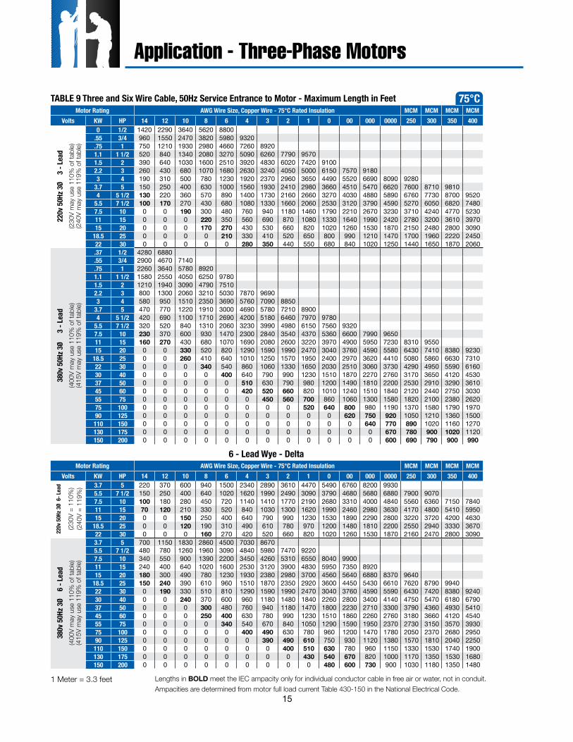
75°C
Application - Three-Phase Motors
Motor Rating AWG Wire Size, Copper Wire - 75°C Rated Insulation MCM MCM MCM MCMVolts KW HP 14 12 10 8 6 4 3 2 1 0 00 000 0000 250 300 350 400
220v
50H
z 3Ø
3
- Lea
d(2
30V
may
use
110
% o
f tab
le)
(240
V m
ay u
se 1
19%
of t
able)
0 1/2 1420 2290 3640 5620 8800.55 3/4 960 1550 2470 3820 5980 9320.75 1 750 1210 1930 2980 4660 7260 89201.1 1 1/2 520 840 1340 2080 3270 5090 6260 7790 95701.5 2 390 640 1030 1600 2510 3920 4830 6020 7420 91002.2 3 260 430 680 1070 1680 2630 3240 4050 5000 6150 7570 91803 4 190 310 500 780 1230 1920 2370 2960 3650 4490 5520 6690 8090 9280
3.7 5 150 250 400 630 1000 1560 1930 2410 2980 3660 4510 5470 6620 7600 8710 98104 5 1/2 130 220 360 570 890 1400 1730 2160 2660 3270 4030 4880 5890 6760 7730 8700 9520
5.5 7 1/2 100 170 270 430 680 1080 1330 1660 2060 2530 3120 3790 4590 5270 6050 6820 74807.5 10 0 0 190 300 480 760 940 1180 1460 1790 2210 2670 3230 3710 4240 4770 523011 15 0 0 0 220 350 560 690 870 1080 1330 1640 1990 2420 2780 3200 3610 397015 20 0 0 0 170 270 430 530 660 820 1020 1260 1530 1870 2150 2480 2800 3090
18.5 25 0 0 0 0 210 330 410 520 650 800 990 1210 1470 1700 1960 2220 245022 30 0 0 0 0 0 280 350 440 550 680 840 1020 1250 1440 1650 1870 2060
380v
50H
z 3Ø
3
- Le
ad(4
00V
may
use
110
% o
f tab
le)
(415
V m
ay u
se 1
19%
of t
able)
.37 1/2 4280 6880
.55 3/4 2900 4670 7140
.75 1 2260 3640 5780 89201.1 1 1/2 1580 2550 4050 6250 97801.5 2 1210 1940 3090 4790 75102.2 3 800 1300 2060 3210 5030 7870 96903 4 580 950 1510 2350 3690 5760 7090 8850
3.7 5 470 770 1220 1910 3000 4690 5780 7210 89004 5 1/2 420 690 1100 1710 2690 4200 5180 6460 7970 9780
5.5 7 1/2 320 520 840 1310 2060 3230 3990 4980 6150 7560 93207.5 10 230 370 600 930 1470 2300 2840 3540 4370 5360 6600 7990 965011 15 160 270 430 680 1070 1690 2080 2600 3220 3970 4900 5950 7230 8310 955015 20 0 0 330 520 820 1290 1590 1990 2470 3040 3760 4590 5580 6430 7410 8380 9230
18.5 25 0 0 260 410 640 1010 1250 1570 1950 2400 2970 3620 4410 5080 5860 6630 731022 30 0 0 0 340 540 860 1060 1330 1650 2030 2510 3060 3730 4290 4950 5590 616030 40 0 0 0 0 400 640 790 990 1230 1510 1870 2270 2760 3170 3650 4120 453037 50 0 0 0 0 0 510 630 790 980 1200 1490 1810 2200 2530 2910 3290 361045 60 0 0 0 0 0 420 520 660 820 1010 1240 1510 1840 2120 2440 2750 303055 75 0 0 0 0 0 0 450 560 700 860 1060 1300 1580 1820 2100 2380 262075 100 0 0 0 0 0 0 0 0 520 640 800 980 1190 1370 1580 1790 197090 125 0 0 0 0 0 0 0 0 0 0 620 750 920 1050 1210 1360 1500110 150 0 0 0 0 0 0 0 0 0 0 0 640 770 890 1020 1160 1270130 175 0 0 0 0 0 0 0 0 0 0 0 0 670 780 900 1020 1120150 200 0 0 0 0 0 0 0 0 0 0 0 0 600 690 790 900 990
6 - Lead Wye - Delta Motor Rating AWG Wire Size, Copper Wire - 75°C Rated Insulation MCM MCM MCM MCM
Volts KW HP 14 12 10 8 6 4 3 2 1 0 00 000 0000 250 300 350 400
220v
50H
z 3Ø
6- L
ead
(230
V =
110%
) (2
40V
= 11
9%) 3.7 5 220 370 600 940 1500 2340 2890 3610 4470 5490 6760 8200 9930
5.5 7 1/2 150 250 400 640 1020 1620 1990 2490 3090 3790 4680 5680 6880 7900 90707.5 10 100 180 280 450 720 1140 1410 1770 2190 2680 3310 4000 4840 5560 6360 7150 784011 15 70 120 210 330 520 840 1030 1300 1620 1990 2460 2980 3630 4170 4800 5410 595015 20 0 0 150 250 400 640 790 990 1230 1530 1890 2290 2800 3220 3720 4200 4630
18.5 25 0 0 120 190 310 490 610 780 970 1200 1480 1810 2200 2550 2940 3330 367022 30 0 0 0 160 270 420 520 660 820 1020 1260 1530 1870 2160 2470 2800 3090
380v
50H
z 3Ø
6
- Lea
d(4
00V
may
use
110
% o
f tab
le)
(415
V m
ay u
se 1
19%
of t
able)
3.7 5 700 1150 1830 2860 4500 7030 86705.5 7 1/2 480 780 1260 1960 3090 4840 5980 7470 92207.5 10 340 550 900 1390 2200 3450 4260 5310 6550 8040 990011 15 240 400 640 1020 1600 2530 3120 3900 4830 5950 7350 892015 20 180 300 490 780 1230 1930 2380 2980 3700 4560 5640 6880 8370 9640
18.5 25 150 240 390 610 960 1510 1870 2350 2920 3600 4450 5430 6610 7620 8790 994022 30 0 190 330 510 810 1290 1590 1990 2470 3040 3760 4590 5590 6430 7420 8380 924030 40 0 0 240 370 600 960 1180 1480 1840 2260 2800 3400 4140 4750 5470 6180 679037 50 0 0 0 300 480 760 940 1180 1470 1800 2230 2710 3300 3790 4360 4930 541045 60 0 0 0 250 400 630 780 990 1230 1510 1860 2260 2760 3180 3660 4120 454055 75 0 0 0 0 340 540 670 840 1050 1290 1590 1950 2370 2730 3150 3570 393075 100 0 0 0 0 0 400 490 630 780 960 1200 1470 1780 2050 2370 2680 295090 125 0 0 0 0 0 0 390 490 610 750 930 1120 1380 1570 1810 2040 2250110 150 0 0 0 0 0 0 0 400 510 630 780 960 1150 1330 1530 1740 1900130 175 0 0 0 0 0 0 0 0 430 540 670 820 1000 1170 1350 1530 1680150 200 0 0 0 0 0 0 0 0 0 480 600 730 900 1030 1180 1350 1480
Lengths in BOLD meet the IEC ampacity only for individual conductor cable in free air or water, not in conduit.Ampacities are determined from motor full load current Table 430-150 in the National Electrical Code.
TABLE 9 Three and Six Wire Cable, 50Hz Service Entrance to Motor - Maximum Length in Feet
1 Meter = 3.3 feet
16
TypeMotor Model Prefix
Nameplate Rating Full Load Watts
Line to Line (1) Resistance (Ohms)
Efficiency % Power Factor % Locked
Rotor Amps
Circuit Breakers or Fuse Amps
Typical SubmersibleNontime Delay (Std.) Fuse or Circuit Breaker
Dual Element Time Delay FuseKW HP Volts Amps F.L. F.L.
4 Inch
234551.37 1/2
220 1.8 560 18.3 - 22.4 66 82 7.3 15 2.5
234561 380 1.1 560 56.8 - 69.4 66 82 4.3 15 1.2
234552.55 3/4
220 2.6 810 12.3 - 15.0 69 83 10 15 3
234562 380 1.6 810 38.6 - 47.2 69 86 5.9 15 1.8
2345530.75 1
220 3.5 1055 8.4 - 10.3 71 83 15 15 4
234563 380 2.1 1055 26.1 - 31.9 71 83 9.0 15 2.5
2345541.1 1 1/2
220 5.2 1465 4.3 - 5.2 76 83 24 15 6
234524 380 3.0 1465 13.2 - 16.2 76 83 14 15 3
2343551.5 2
220 6.9 1970 3.0 - 3.7 76 84 35 15 8
234325 380 4.0 1970 9.4 - 11.5 76 84 20 15 4.5
234356
2.2 3
220 10.4 2930 2.1 - 2.7 76 86 46 25 12
234326
380 6.0 2930
6.7 - 8.2
76 86 26
15 7400 6.0 2920 77 82 27
415 6.2 2925 77 77 28
234394
3 4
220 12.6 3940 1.5 - 1.8 76 87 64 35 15
234395
380 7.3 3940
4.9 - 6.0
76 87 36
20 9400 7.3 3910 76 84 38
415 7.6 3920 76 81 39
234357
3.7 5
220 15.5 4860 1.1 - 1.4 77 84 80 40 20
234327
380 9.0 4860
3.6 - 4.4
77 84 46
25 10400 9.1 4875 77 79 48
415 9.5 4910 76 74 49
234396
4 5 1/2
220 18.0 5275 1.0 - 1.3 78 86 89 45 20
234397
380 10.1 5275
3.2 - 3.9
78 86 51
25 12400 10.4 5210 79 82 53
415 10.6 5240 78 79 55
234358
5.5 7 1/2
220 22.8 7175 .75 - .92 78 85 120 60 30
234328
380 13.0 7175
2.3 - 2.8
78 85 69
35 15400 13.1 7155 78 80 73
415 13.5 7205 78 76 76
234595 7.5 10380 18.7 9580
1.7 - 2.178 86 99
50 25400 18.8 9550 78 81 102
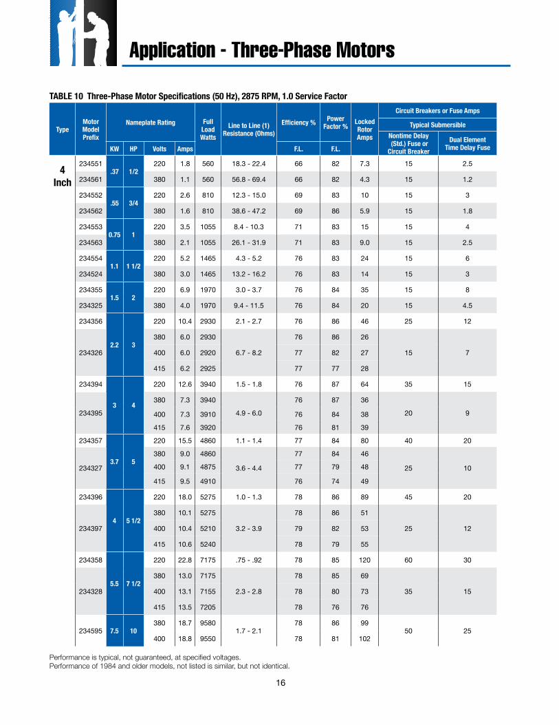
TABLE 10 Three-Phase Motor Specifications (50 Hz), 2875 RPM, 1.0 Service Factor
Performance is typical, not guaranteed, at specified voltages. Performance of 1984 and older models, not listed is similar, but not identical.
Application - Three-Phase Motors
17
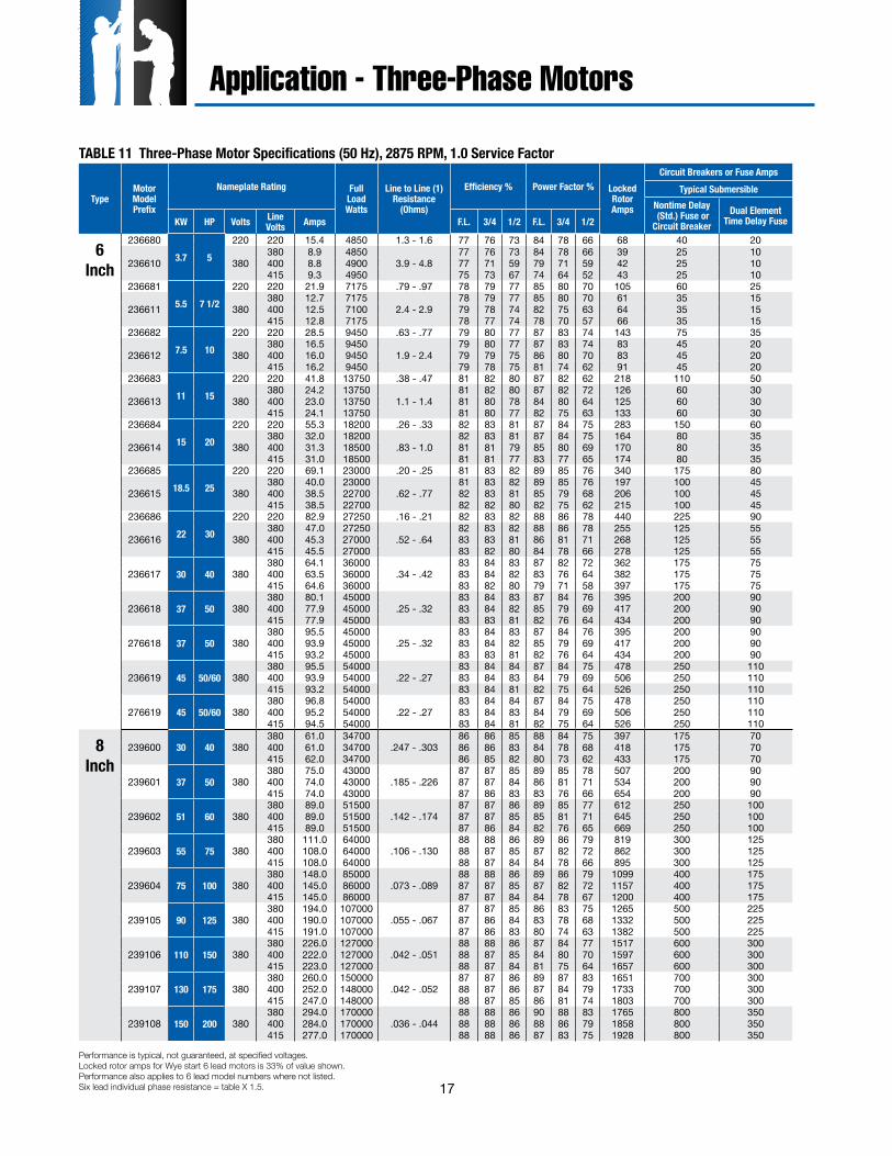
TABLE 11 Three-Phase Motor Specifications (50 Hz), 2875 RPM, 1.0 Service Factor
TypeMotorModelPrefix
Nameplate Rating FullLoadWatts
Line to Line (1)Resistance
(Ohms)
Efficiency % Power Factor % LockedRotorAmps
Circuit Breakers or Fuse AmpsTypical Submersible
Nontime Delay (Std.) Fuse or Circuit Breaker
Dual Element Time Delay FuseKW HP Volts Line
Volts Amps F.L. 3/4 1/2 F.L. 3/4 1/2
6Inch
2366803.7 5
220 220 15.4 4850 1.3 - 1.6 77 76 73 84 78 66 68 40 20
236610 380380 8.9 4850
3.9 - 4.877 76 73 84 78 66 39 25 10
400 8.8 4900 77 71 59 79 71 59 42 25 10415 9.3 4950 75 73 67 74 64 52 43 25 10
2366815.5 7 1/2
220 220 21.9 7175 .79 - .97 78 79 77 85 80 70 105 60 25
236611 380380 12.7 7175
2.4 - 2.978 79 77 85 80 70 61 35 15
400 12.5 7100 79 78 74 82 75 63 64 35 15415 12.8 7175 78 77 74 78 70 57 66 35 15
2366827.5 10
220 220 28.5 9450 .63 - .77 79 80 77 87 83 74 143 75 35
236612 380380 16.5 9450
1.9 - 2.479 80 77 87 83 74 83 45 20
400 16.0 9450 79 79 75 86 80 70 83 45 20415 16.2 9450 79 78 75 81 74 62 91 45 20
23668311 15
220 220 41.8 13750 .38 - .47 81 82 80 87 82 62 218 110 50
236613 380380 24.2 13750
1.1 - 1.481 82 80 87 82 72 126 60 30
400 23.0 13750 81 80 78 84 80 64 125 60 30415 24.1 13750 81 80 77 82 75 63 133 60 30
23668415 20
220 220 55.3 18200 .26 - .33 82 83 81 87 84 75 283 150 60
236614 380380 32.0 18200
.83 - 1.082 83 81 87 84 75 164 80 35
400 31.3 18500 81 81 79 85 80 69 170 80 35415 31.0 18500 81 81 77 83 77 65 174 80 35
23668518.5 25
220 220 69.1 23000 .20 - .25 81 83 82 89 85 76 340 175 80
236615 380380 40.0 23000
.62 - .7781 83 82 89 85 76 197 100 45
400 38.5 22700 82 83 81 85 79 68 206 100 45415 38.5 22700 82 82 80 82 75 62 215 100 45
23668622 30
220 220 82.9 27250 .16 - .21 82 83 82 88 86 78 440 225 90
236616 380380 47.0 27250
.52 - .6482 83 82 88 86 78 255 125 55
400 45.3 27000 83 83 81 86 81 71 268 125 55415 45.5 27000 83 82 80 84 78 66 278 125 55
236617 30 40 380380 64.1 36000
.34 - .4283 84 83 87 82 72 362 175 75
400 63.5 36000 83 84 82 83 76 64 382 175 75415 64.6 36000 83 82 80 79 71 58 397 175 75
236618 37 50 380380 80.1 45000
.25 - .3283 84 83 87 84 76 395 200 90
400 77.9 45000 83 84 82 85 79 69 417 200 90415 77.9 45000 83 83 81 82 76 64 434 200 90
276618 37 50 380380 95.5 45000
.25 - .3283 84 83 87 84 76 395 200 90
400 93.9 45000 83 84 82 85 79 69 417 200 90415 93.2 45000 83 83 81 82 76 64 434 200 90
236619 45 50/60 380380 95.5 54000
.22 - .2783 84 84 87 84 75 478 250 110
400 93.9 54000 83 84 83 84 79 69 506 250 110415 93.2 54000 83 84 81 82 75 64 526 250 110
276619 45 50/60 380380 96.8 54000
.22 - .2783 84 84 87 84 75 478 250 110
400 95.2 54000 83 84 83 84 79 69 506 250 110415 94.5 54000 83 84 81 82 75 64 526 250 110
8Inch
239600 30 40 380380 61.0 34700
.247 - .30386 86 85 88 84 75 397 175 70
400 61.0 34700 86 86 83 84 78 68 418 175 70415 62.0 34700 86 85 82 80 73 62 433 175 70
239601 37 50 380380 75.0 43000
.185 - .22687 87 85 89 85 78 507 200 90
400 74.0 43000 87 87 84 86 81 71 534 200 90415 74.0 43000 87 86 83 83 76 66 654 200 90
239602 51 60 380380 89.0 51500
.142 - .17487 87 86 89 85 77 612 250 100
400 89.0 51500 87 87 85 85 81 71 645 250 100415 89.0 51500 87 86 84 82 76 65 669 250 100
239603 55 75 380380 111.0 64000
.106 - .13088 88 86 89 86 79 819 300 125
400 108.0 64000 88 87 85 87 82 72 862 300 125415 108.0 64000 88 87 84 84 78 66 895 300 125
239604 75 100 380380 148.0 85000
.073 - .08988 88 86 89 86 79 1099 400 175
400 145.0 86000 87 87 85 87 82 72 1157 400 175415 145.0 86000 87 87 84 84 78 67 1200 400 175
239105 90 125 380380 194.0 107000
.055 - .06787 87 85 86 83 75 1265 500 225
400 190.0 107000 87 86 84 83 78 68 1332 500 225415 191.0 107000 87 86 83 80 74 63 1382 500 225
239106 110 150 380380 226.0 127000
.042 - .05188 88 86 87 84 77 1517 600 300
400 222.0 127000 88 87 85 84 80 70 1597 600 300415 223.0 127000 88 87 84 81 75 64 1657 600 300
239107 130 175 380380 260.0 150000
.042 - .05287 87 86 89 87 83 1651 700 300
400 252.0 148000 88 87 86 87 84 79 1733 700 300415 247.0 148000 88 87 85 86 81 74 1803 700 300
239108 150 200 380380 294.0 170000
.036 - .04488 88 86 90 88 83 1765 800 350
400 284.0 170000 88 88 86 88 86 79 1858 800 350415 277.0 170000 88 88 86 87 83 75 1928 800 350
Performance is typical, not guaranteed, at specified voltages. Locked rotor amps for Wye start 6 lead motors is 33% of value shown. Performance also applies to 6 lead model numbers where not listed. Six lead individual phase resistance = table X 1.5.
Application - Three-Phase Motors
18
TypeMotor Model Prefix
Nameplate RatingFull Load Watts Line to Line (1)
Resistance (Ohms)8Efficiency % Power Factor % Locked
Rotor AmpsKW HP Volts Line
Volts Amps F.L. 3/4 1/2 F.L. 3/4 1/2
6 IN
CH
HI-T
emp
90C
276 610 3.7 5 380-415380 8.8 5000
2.79 - 3.4174 72 66 88 85 78 49.9
400 8.5 5000 75 72 66 86 82 74 52.5415 8.4 5000 75 72 65 84 79 70 54.5
276 611 5.5 7.5 380-415380 12.7 7300
1.66 - 2.0377 75 70 88 85 77 78.6
400 12.3 7200 77 75 70 86 81 72 83.0415 12.3 7200 77 75 69 84 77 67 86.0
276 612 7.5 10 380-415380 24.4 9400
1.18 - 1.4480 78 74 88 84 76 105
400 24.2 9300 81 79 74 85 79 69 110415 24.4 9400 80 77 71 83 76 65 114
276 613 11 15 380-415380 33.3 13900
.78 - .9680 79 75 85 83 74 152
400 33.0 13800 80 79 74 82 77 67 160415 33.3 14000 79 78 73 79 73 61 166
276 614 15 20 380-415380 40.7 18700
.58 - .7280 79 76 87 82 73 195
400 40.5 18700 80 79 75 83 77 65 205415 41.4 18700 80 78 74 80 72 60 213
276 615 18.5 25 380-415380 49.2 22600
.41 - .5182 82 79 86 80 70 253
400 48.0 22500 83 82 78 82 74 62 266415 47.9 22700 82 80 76 78 69 57 276
276 616 22 30 380-415380 65.0 27800
.34 -.4280 79 76 88 83 76 289
400 64.5 27700 81 79 75 85 80 70 304415 65.6 27800 80 79 74 82 76 65 316
276 617 30 40 380-415380 65.5 35900
.23 -.2983 82 80 86 80 70 419
400 64.5 35800 83 82 79 82 75 63 441415 65.6 36000 83 81 77 78 70 58 458
8 IN
CH
HI-T
emp
75C
279 100 30 40 380-415380 66.8 37000
.16 - .1980 78 72 0.86 0.82 0.76 474
400 65.5 37000 80 78 72 0.83 0.78 0.7 499415 65.8 37000 80 77 71 0.8 0.74 0.65 518
279 101 37 50 380-415380 80.7 45000
.11 - .1483 80 75 0.87 0.83 0.76 654
400 79.6 45000 82 80 74 0.84 0.79 0.7 692415 80.1 46000 82 79 73 0.81 0.75 0.65 720
279 102 45 60 380-415380 94.3 53000
.09 - .1185 83 78 0.87 0.82 0.75 835
400 93.1 53000 84 82 77 0.84 1.78 0.69 884415 93 53000 84 82 76 0.81 0.74 0.64 920
279 103 55 75 380-415380 118 67000
.07 - .0984 82 78 0.87 0.84 0.77 876
400 115 66000 84 82 78 0.85 0.81 0.72 927415 113 66000 84 82 77 0.83 0.78 0.69 965
279 104 75 100 380-415380 155 87000
.05 - .0785 84 81 0.87 0.83 0.76 1185
400 151 87000 86 84 80 0.85 0.8 0.71 1254415 150 87000 85 84 80 0.82 0.78 0.66 1306
279 105 93 125 380-415380 191 109000
.04 - .0686 85 81 0.88 0.85 0.78 1404
400 186 109000 86 84 81 0.86 0.8 0.73 1482415 184 109000 86 84 80 0.84 0.76 0.69 1544
279 106 110 150 380-415380 231 131000
.03 - .0585 84 81 0.88 0.84 0.77 1596
400 224 130000 86 84 81 0.85 0.81 0.72 1690415 222 130000 86 84 80 0.83 0.77 0.68 1760
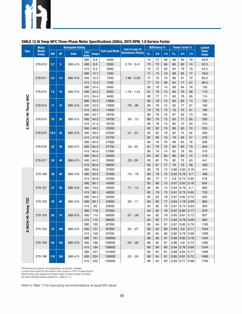
TABLE 12 Hi Temp 90oC Three-Phase Motor Specifications (50Hz), 2875 RPM, 1.0 Service Factor
Performance is typical, not guaranteed, at specific voltages. Locked rotor amps for Wye start 6 lead motors is 33% of value shown. Performance also applies to 6 lead model numbers where not listed. Six lead individual phase resistance = table X 1.5.
Refer to Table 17 for fuse sizing recommendations at equal KW values.
19
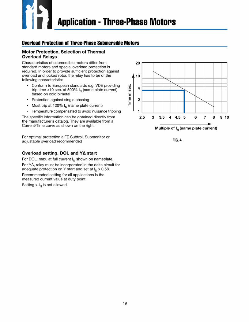
Overload Protection of Three-Phase Submersible MotorsMotor Protection, Selection of Thermal Overload RelaysCharacteristics of submersible motors differ from standard motors and special overload protection is required. In order to provide sufficient protection against overload and locked rotor, the relay has to be of the following characteristic:
• Conform to European standards e.g. VDE providing trip time <10 sec. at 500% IN (name plate current) based on cold bimetal
• Protection against single phasing• Must trip at 120% IN (name plate current)• Temperature compensated to avoid nuisance tripping
The specific information can be obtained directly from the manufacturer’s catalog. They are available from a Current/Time curve as shown on the right.
For optimal protection a FE Subtrol, Submonitor or adjustable overload recommended
Overload setting, DOL and Y∆ startFor DOL, max. at full current IN shown on nameplate.For Y∆, relay must be incorporated in the delta circuit for adequate protection on Y start and set at IN x 0.58.Recommended setting for all applications is the measured current value at duty point.Setting > IN is not allowed.
Multiple of IN (name plate current)Ti
me
in s
ec.
20
10
4
2
12.5 3 3.5 4 4.5 5 6 7 8 9 10
Application - Three-Phase Motors
FIG. 4
20
Application - Three-Phase Motors
SubMonitor Three- Phase Protection
Power Factor CorrectionIn some installations, power supply limitations make it necessary or desirable to increase the power factor of a submersible motor. The table lists the capacitive KVAR required to increase the power factor of large Franklin three-phase submersible motors to the approximate values shown at maximum input loading.Capacitors must be connected on the line side of the overload relay, or overload protection will be lost.
Motor KVAR Required for P.F. of:
KW HP 0.90 0.95 1.00
3.7 5 .8 1.5 3.1
5.5 7 1/2 1.0 2.1 4.5
7.5 10 .8 2.2 5.3
11 15 1.1 3.3 7.8
15 20 1.8 4.3 9.6
18.5 25 3 6.5 14
22 30 3 7.5 17
30 40 5 10 22
37 50 5 12 27
45 60 5 13 30
55 75 5 15 37
75 100 4 18 46
90 125 18 35 72
110 150 18 38 82
130 175 13 37 88
150 200 10 37 95
Values listed are total required (not per phase).
TABLE 13 KVAR Required 50 Hz
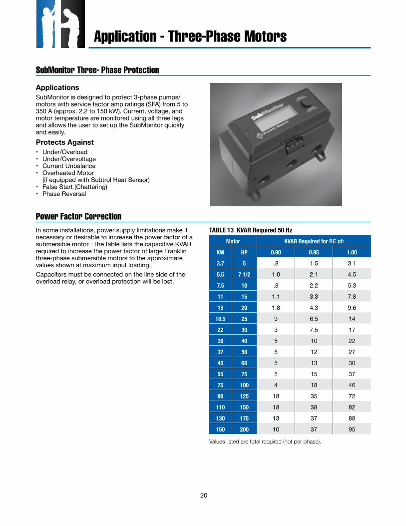
ApplicationsSubMonitor is designed to protect 3-phase pumps/ motors with service factor amp ratings (SFA) from 5 to 350 A (approx. 2.2 to 150 kW). Current, voltage, and motor temperature are monitored using all three legs and allows the user to set up the SubMonitor quickly and easily.Protects Against• Under/Overload • Under/Overvoltage • Current Unbalance • Overheated Motor (if equipped with Subtrol Heat Sensor) • False Start (Chattering) • Phase Reversal
21
Application - Three-Phase Motors
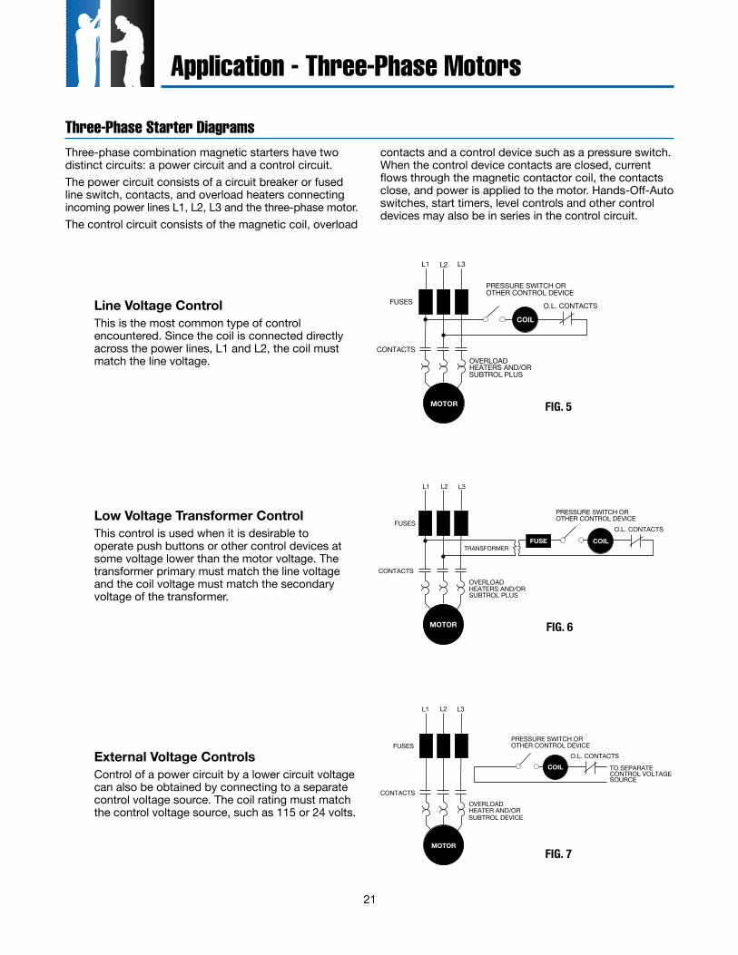
Three-Phase Starter DiagramsThree-phase combination magnetic starters have two distinct circuits: a power circuit and a control circuit.The power circuit consists of a circuit breaker or fused line switch, contacts, and overload heaters connecting incoming power lines L1, L2, L3 and the three-phase motor.The control circuit consists of the magnetic coil, overload
contacts and a control device such as a pressure switch. When the control device contacts are closed, current flows through the magnetic contactor coil, the contacts close, and power is applied to the motor. Hands-Off-Auto switches, start timers, level controls and other control devices may also be in series in the control circuit.
O.L. CONTACTS
PRESSURE SWITCH OROTHER CONTROL DEVICE
COIL
L1 L2 L3
FUSES
CONTACTSOVERLOADHEATERS AND/OR
MOTOR
SUBTROL PLUS
O.L. CONTACTS
PRESSURE SWITCH OROTHER CONTROL DEVICE
L1 L2 L3
FUSES
CONTACTSOVERLOADHEATERS AND/OR
TRANSFORMER
SUBTROL PLUS
MOTOR
COILFUSE
O.L. CONTACTS
PRESSURE SWITCH OROTHER CONTROL DEVICE
L1 L2 L3
FUSES
CONTACTSOVERLOADHEATER AND/OR
MOTOR
COIL TO SEPARATECONTROL VOLTAGESOURCE
SUBTROL DEVICE
FIG. 5
FIG. 6
FIG. 7
Line Voltage Control This is the most common type of control
encountered. Since the coil is connected directly across the power lines, L1 and L2, the coil must match the line voltage.
Low Voltage Transformer Control This control is used when it is desirable to
operate push buttons or other control devices at some voltage lower than the motor voltage. The transformer primary must match the line voltage and the coil voltage must match the secondary voltage of the transformer.
External Voltage Controls Control of a power circuit by a lower circuit voltage
can also be obtained by connecting to a separate control voltage source. The coil rating must match the control voltage source, such as 115 or 24 volts.
22
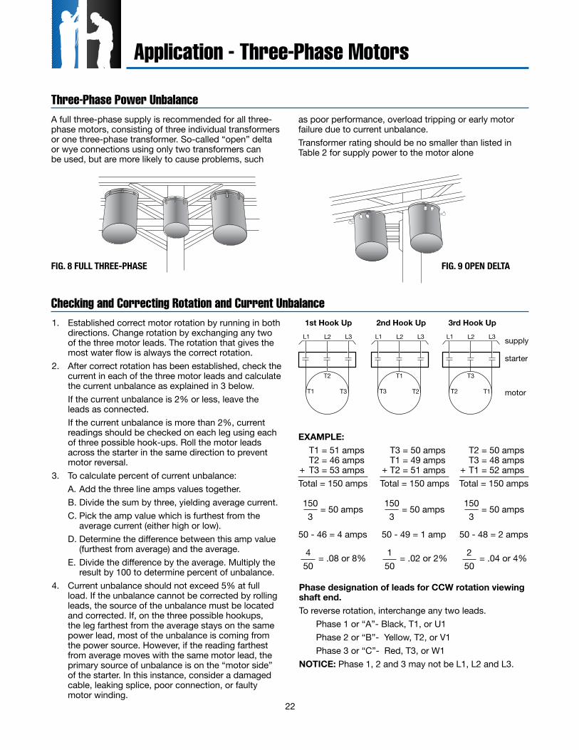
Three-Phase Power UnbalanceA full three-phase supply is recommended for all three-phase motors, consisting of three individual transformers or one three-phase transformer. So-called “open” delta or wye connections using only two transformers can be used, but are more likely to cause problems, such
as poor performance, overload tripping or early motor failure due to current unbalance.Transformer rating should be no smaller than listed in Table 2 for supply power to the motor alone
Checking and Correcting Rotation and Current Unbalance1. Established correct motor rotation by running in both
directions. Change rotation by exchanging any two of the three motor leads. The rotation that gives the most water flow is always the correct rotation.
2. After correct rotation has been established, check the current in each of the three motor leads and calculate the current unbalance as explained in 3 below.
If the current unbalance is 2% or less, leave the leads as connected.
If the current unbalance is more than 2%, current readings should be checked on each leg using each of three possible hook-ups. Roll the motor leads across the starter in the same direction to prevent motor reversal.
3. To calculate percent of current unbalance: A. Add the three line amps values together. B. Divide the sum by three, yielding average current. C. Pick the amp value which is furthest from the
average current (either high or low). D. Determine the difference between this amp value
(furthest from average) and the average. E. Divide the difference by the average. Multiply the
result by 100 to determine percent of unbalance.4. Current unbalance should not exceed 5% at full
load. If the unbalance cannot be corrected by rolling leads, the source of the unbalance must be located and corrected. If, on the three possible hookups, the leg farthest from the average stays on the same power lead, most of the unbalance is coming from the power source. However, if the reading farthest from average moves with the same motor lead, the primary source of unbalance is on the “motor side” of the starter. In this instance, consider a damaged cable, leaking splice, poor connection, or faulty motor winding.
Phase designation of leads for CCW rotation viewing shaft end.To reverse rotation, interchange any two leads.
Phase 1 or “A”- Black, T1, or U1Phase 2 or “B”- Yellow, T2, or V1Phase 3 or “C”- Red, T3, or W1
NOTICE: Phase 1, 2 and 3 may not be L1, L2 and L3.
FIG. 8 FULL THREE-PHASE FIG. 9 OPEN DELTA
EXAMPLE: T1 = 51 amps T3 = 50 amps T2 = 50 amps
T2 = 46 amps T1 = 49 amps T3 = 48 amps T3 = 53 amps T2 = 51 amps T1 = 52 amps
Total = 150 amps Total = 150 amps Total = 150 amps+++
150 3
= 50 amps 150 3
= 50 amps1503
= 50 amps
50 - 46 = 4 amps 50 - 49 = 1 amp 50 - 48 = 2 amps
450
= .08 or 8% 150
= .02 or 2% 250
= .04 or 4%
T2
T1 T3
L1 L2 L3
T1
T3 T2
L1 L2 L3
T3
T2 T1
L1 L2 L3
1st Hook Up 2nd Hook Up 3rd Hook Up
supply
starter
motor
Application - Three-Phase Motors

Submersible Pump Installation Check List
1. Motor Inspection
*A. Verify that the model, hp or kW, voltage, phase and hertz on the motor nameplate match the installation requirements.
*B. Check that the motor lead assembly is not damaged.
*C. Measure insulation resistance using a 500 or 1000 volt DC megohmmeter from each lead wire to the motor frame. Resistance should be at least 200 megohms without drop cable.
*D. Keep a record of motor model number, hp or kW, voltage, and serial number (S/N). (S/N is stamped in shell above the nameplate. A typical example, S/N 07A18 01-0123)
2. Pump Inspection
*A. Check that the pump rating matches the motor.
*B. Check for pump damage and verify that the pump shaft turns freely.
3. Pump/Motor Assembly
*A. If not yet assembled, check that pump and motor mounting faces are free from dirt, debris and uneven paint thickness.
*B. Pumps and motors over 5 hp should be assembled in the vertical position to prevent stress on pump brackets and shafts. Assemble the pump and motor together so their mounting faces are in contact and then tighten assembly bolts or nuts evenly to manufacturer specifications.
*C. If accessible, check that the pump shaft turns freely.
*D. Assemble the pump lead guard over the motor leads. Do not cut or pinch lead wires during assembly or installation.
4. Power Supply and Controls
*A. Verify that the power supply voltage, Hertz, and kVA capacity match motor requirements.
*B. Verify control box hp and voltage matches motor (3-wire only).
*C. Check that the electrical installation and controls meet all safety regulations and match the motor requirements, including fuse or circuit breaker size and motor overload protection. Connect all metal plumbing and electrical enclosures to the power supply ground to prevent shock hazard. Comply with national and local codes.
5. Lightning and Surge Protection
*A. Use properly rated surge (lightning) arrestors on all submersible pump installations. Motors 5 hp and smaller, which are marked “Equipped with Lightning Arrestors”, contain internal arrestors.
*B. Ground all above ground arrestors with copper wire directly to the motor frame, or to metal drop pipe or casing which reaches below the well pumping level. Connecting to a ground rod does not provide good surge protection.
6. Electrical Drop Cable
*A. Use submersible cable sized in accordance with local regulations and the cable charts. See pages 11 and 16-21. Ground motor per national and local codes.
*B. Include a ground wire to the motor and surge protection, connected to the power supply ground if required by codes. Always ground any pump operated outside a drilled well.
7. Motor Cooling
*A. Ensure at all times that the installation provides adequate motor cooling; see page 6 for details.
Form No. 3656 04/2013 © 2013 Franklin Electric Co., Inc.
This material may be reproduced in its entirety for personal and educational purposes, including reproduction in technical specifications and manuals, without prior permission, provided that the above copyright notice is included in all copies or substantial portions of the material. All other rights reserved.

Submersible Pump Installation Check List
8. Pump/Motor Installation
*A. Splice motor leads to supply cable using electrical grade solder or compression connectors, and carefully insulate each splice with watertight tape or adhesive-lined shrink tubing, as shown in motor or pump installation data.
*B. Support the cable to the delivery pipe every 10 feet (3 meters) with straps or tape strong enough to prevent sagging. Use padding between cable and any metal straps.
*C. A check valve in the delivery pipe is recommended. More than one check valve may be required, depending on valve rating and pump setting; see page 5 for details.
*D. Assemble all pipe joints as tightly as practical, to prevent unscrewing from motor torque. Torque should be at least 10 pound feet per hp (2 meter-KG per kW).
*E. Set the pump far enough below the lowest pumping level to assure the pump inlet will always have at least the Net Positive Suction Head (NPSH) specified by the pump manufacturer. Pump should be at least 10 feet (3 meters) from the bottom of the well to allow for sediment build up.
*F. Check insulation resistance as pump/motor assembly is lowered into the well. Resistance may drop gradually as more cable enters the water, but any sudden drop indicates possible cable, splice or motor lead damage; see page 45.
9. After Installation
*A. Check all electrical and water line connections and parts before starting the pump.
*B. Start the pump and check motor amps and pump delivery. If normal, continue to run the pump until delivery is clear. If three-phase pump delivery is low, it may be running backward. Rotation may be reversed (with power off) by interchanging any two motor lead connections to the power supply.
*C. Check three-phase motors for current balance within 5% of average, using motor manufacturer instructions Imbalance over 5% will cause higher motor temperatures and may cause overload trip, vibration, and reduced life.
*D. Verify that starting, running and stopping cause no significant vibration or hydraulic shocks.
*E. After at least 15 minutes running time, verify that pump output, electrical input, pumping level, and other characteristics are stable and as specified.
Date _____________________ Filled In By _________________________________________________________________
Notes _______________________________________________________________________________________________
____________________________________________________________________________________________________
____________________________________________________________________________________________________
____________________________________________________________________________________________________
____________________________________________________________________________________________________
____________________________________________________________________________________________________Form No. 3656 04/2013 © 2013 Franklin Electric Co., Inc.
This material may be reproduced in its entirety for personal and educational purposes, including reproduction in technical specifications and manuals, without prior permission, provided that the above copyright notice is included in all copies or substantial portions of the material. All other rights reserved.
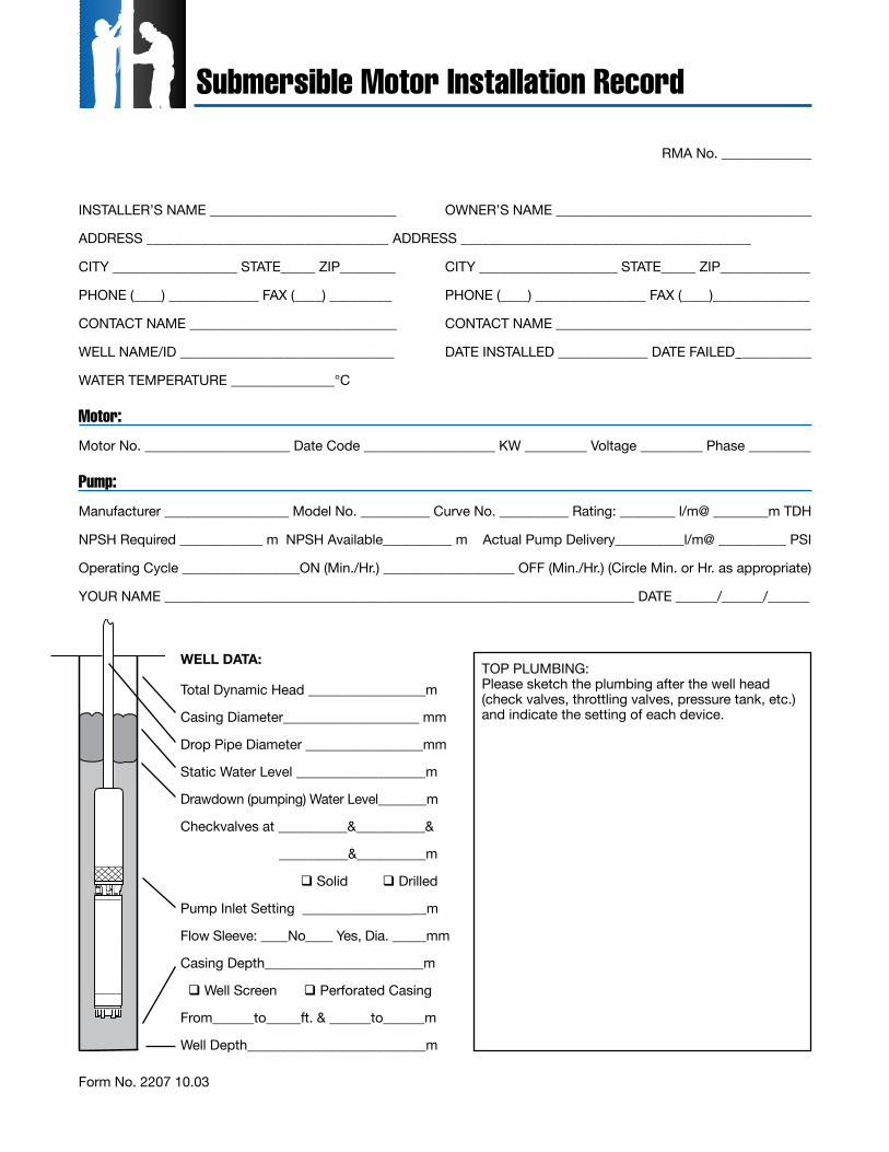
RMA No. _____________
INSTALLER’S NAME ___________________________ OWNER’S NAME _____________________________________
ADDRESS ___________________________________ ADDRESS __________________________________________
CITY __________________ STATE_____ ZIP________ CITY ____________________ STATE_____ ZIP_____________
PHONE (____) _____________ FAX (____) _________ PHONE (____) ________________ FAX (____)______________
CONTACT NAME ______________________________ CONTACT NAME _____________________________________
WELL NAME/ID _______________________________ DATE INSTALLED _____________ DATE FAILED __________
WATER TEMPERATURE _______________°C
Motor:
Motor No. _____________________ Date Code ___________________ KW _________ Voltage _________ Phase _________
Pump:
Manufacturer __________________ Model No. __________ Curve No. __________ Rating: ________ l/m@ ________m TDH
NPSH Required ____________ m NPSH Available__________ m Actual Pump Delivery__________l/m@ __________ PSI
Operating Cycle _________________ON (Min./Hr.) ___________________ OFF (Min./Hr.) (Circle Min. or Hr. as appropriate)
YOUR NAME ____________________________________________________________________ DATE ______/______/______
WELL DATA:
Total Dynamic Head _________________m
Casing Diameter___________________ mm
Drop Pipe Diameter _________________mm
Static Water Level ___________________m
Drawdown (pumping) Water Level_______m
Checkvalves at __________&__________&
__________&__________m
Solid Drilled
Pump Inlet Setting __________________m
Flow Sleeve: ____No____ Yes, Dia. _____mm
Casing Depth_______________________m
Well Screen Perforated Casing
From______to_____ft. & ______to______m
Well Depth__________________________m
TOP PLUMBING:Please sketch the plumbing after the well head (check valves, throttling valves, pressure tank, etc.) and indicate the setting of each device.
Form No. 2207 10.03
Submersible Motor Installation Record
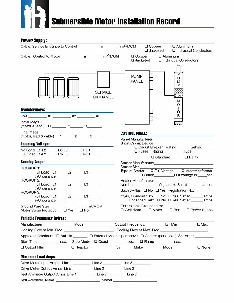
Power Supply:Cable: Service Entrance to Control ____________m _______ mm2/MCM Copper Aluminum Jacketed Individual ConductorsCable: Control to Motor ____________m________mm2/MCM Copper Aluminum Jacketed Individual Conductors
Variable Frequency Drives:Manufacturer_________________ Model ______________ Output Frequency: _________ Hz Min _________ Hz MaxCooling Flow at Min. Freq. ___________________________ Cooling Flow at Max. Freq.__________________________Approved Overload: Built-in ________ External Model: (per above) Cables: (per above) Set Amps __________Start Time ____________sec. Stop Mode Coast __________sec. Ramp __________ sec. Output filter ___________ Reactor _______________% Make __________ Model ___________ None
Maximum Load Amps:Drive Meter Input Amps Line 1 __________ Line 2 __________ Line 3 __________Drive Meter Output Amps Line 1 __________ Line 2 __________ Line 3 __________Test Ammeter Output Amps Line 1 __________ Line 2 __________ Line 3 __________Test Ammeter Make ________________________ Model ________________________
COnTROL PAnEL:Panel Manufacturer_________________________________Short Circuit Device Circuit Breaker Rating________Setting______ Fuses Rating___________ Type___________ Standard DelayStarter Manufacturer________________________________Starter Size ________________________________________Type of Starter Full Voltage Autotransformer Other:___________Full Voltage in _____sec.Heater Manufacturer________________________________Number______________Adjustable Set at ________amps.Subtrol-Plus No Yes Registration No. __________If yes, Overload Set? No Yes Set at _______amps. Underload Set? No Yes Set at _______amps.Controls are Grounded to: Well Head Motor Rod Power Supply
Transformers:KVA __________ #1 __________ #2 __________ #3Initial Megs (motor & lead) T1________T2_______T3________Final Megs (motor, lead & cable) T1______T2______T3______
Incoming Voltage:No Load L1-L2______ L2-L3_______L1-L3_______ Full Load L1-L2______ L2-L3_______L1-L3_______
Running Amps:HOOKUP 1: Full Load L1______L2_______L3_______ %Unbalance______ HOOKUP 2: Full Load L1______L2_______L3_______ %Unbalance______ HOOKUP 3: Full Load L1______L2_______L3_______ %Unbalance______Ground Wire Size ___________________mm2/MCM Motor Surge Protection Yes No
MOTOR
PUMP
PUMPPANEL
SERVICEENTRANCE
Submersible Motor Installation Record

Submersible Motor Booster Installation Record
Date ______ /______ / _______ Filled In By ____________________________________ RMA No. __________________
Installation
Owner/User __________________________________________________ Telephone (________) __________________________Address __________________________________________________ City ____________________________________________ State_____________________________ Postal Code/Zip_________________ Country__________________________________Installation Site, If Different ___________________________________________________________________________________Contact ______________________________________________________ Telephone (________) __________________________System Application_____________________________________________________________________________________________________________________________________________________________________________________________________System Manufactured By_____________________________ Model _________________ Serial No. _____________________System Supplied By___________________________________ City _________________________________________________ State_____________________________ Postal Code/Zip________________ Country__________________________________
Motor
Model No. ____________________________ Serial No. ______________________________ Date Code ___________________Horsepower/kW______________ Voltage ______________ Single-Phase Three-Phase
Motor Diaphragm Height__________________ in mm Motor Shaft Height__________________ in mmSlinger Removed? Yes No Check Valve Plug Removed? Yes No Motor Dia. _________inDoes Motor Have a Deionized Fill Solution: Yes No
Pump
Manufacturer _____________________________ Model ____________________________ Serial No. _____________________Stages __________________ Diameter____________________ Flow Rate Of _______________ GPM At _____________TDHBooster Case Internal Diameter _______________________ Material Construction ____________________________________
Controls and Protective Devices
Subtrol? Yes No If Yes, Warranty Registration No.________________________________________________ If Yes, Overload Set? Yes No ______ Set At ______________________________ Underload Sets? Yes No ______ Set At ______________________________Reduced Voltage Starter? Yes No If Yes, Type ______________________________________________________ Mfr.______________________ Starting______________%Full Voltage Ramp up to Full Voltage In _______________ Sec.Variable Frequency Drive? Yes No If Yes, Mfr. _____________________________ Model__________________Accel. Time 0 to 30Hz:_____________ Sec. Max Freq.____________Volt/HzDecel. Time 30 to 0Hz:_____________ Sec. Min Freq._____________Volt/HzVolt/Hz Profile: _____________________________________________________________________________________________Magnetic Starter/Contactor Mfr. ___________________________ Model ______________________Size_________________Overload Mfr. ________________________________________________________ Ambient Compensated Yes No Overload Class 10 Rated Yes No Htr No._______________ If Adjustable Overload Set At__________________Circuit Protection Fuse Breaker Mfr.______________________ Size________________ Type__________________Lightning/Surge Arrestor Mfr. _____________________________ Model ____________________________________________Controls Are Grounded to __________________ with No. ________ Wire
Submersible Motor Booster Installation Record

Inlet Feed Water Temp Control Required Mfr._____________________________ Model _____________________________
Set At ________ °F °C Delay_____ Sec.
Inlet Pressure Control Required Ea. Mtr. Mfr.______________ Model _____________ Set_________ PSI Delay_____ Sec.
Outlet Flow Control Required Ea. Mtr. Mfr______________ Model ____________ Set________ GPM Delay_____ Sec.
Outlet Pressure Control Required Ea. Mtr. Mfr.______________ Model ____________ Set__________ PSI Delay_____ Sec.
Inlet Flow Control (Optional) If Yes, Mfr.______________ Model ____________ Set___ GPM Delay_____ Sec.
Flushing Is there a flushing cycle? Yes No If Yes, Flushing Occurs: Pre-Operation Yes No If Yes, _______________ Duration in Min. _________ GPM or ________ PSI Post-Operation Yes No If Yes, _______________ Duration in Min. _________ GPM or ________ PSI Chemicals Yes No If Yes, list _________________________________________________________Motor Duty Cycle: Starts Per 24hrs ___________Time Between Shutdown & Start-up _______________________________
Insulation Check
Initial Megs: Motor & Motor Lead Only T1_________ T2________ T3_________ Installed Megs: Motor, Motor Lead, & Cable T1_________ T2________ T3_________ Motor Phase to Phase Resistance T1-T2 ________ T1-T3 ________ T2-T3________
Voltage To Motor
Non-Operating: T1-T2_________ T1-T2_________ T2-T3_________ Operating At Rated Flow ___________ GPM T1-T2_________ T1-T2_________ T2-T3_________ Operating At Open Flow ____________GPM T1-T2_________ T1-T2_________ T2-T3_________
Amps To Motor
Operating At Rated Flow ___________ GPM T1 _________ T2 ________ T3 _________ Operating At Open Flow ____________GPM T1 _________ T2 ________ T3 _________
Current System Reading
Inlet Pressure __________PSI Outlet Pressure __________ PSI Water Temperature _______ °F °C Warranty on three-phase motors is void unless Subtrol or proper quick trip ambient compensated protection is used on all three (3) motor lines.
If you have any questions or problems, call the Franklin Electric Toll-Free Hot Line: 1-800-348-2420
Comments:_____________________________________________________________________________________________________________________________________________________________________________________________________________________________________________________________________________________________________________________________________________________________________________________________________________________________________________________________________________________________________________________________________________Please attach a sketch of the system
Form No. 3655 10.03
Submersible Motor Booster Installation Record
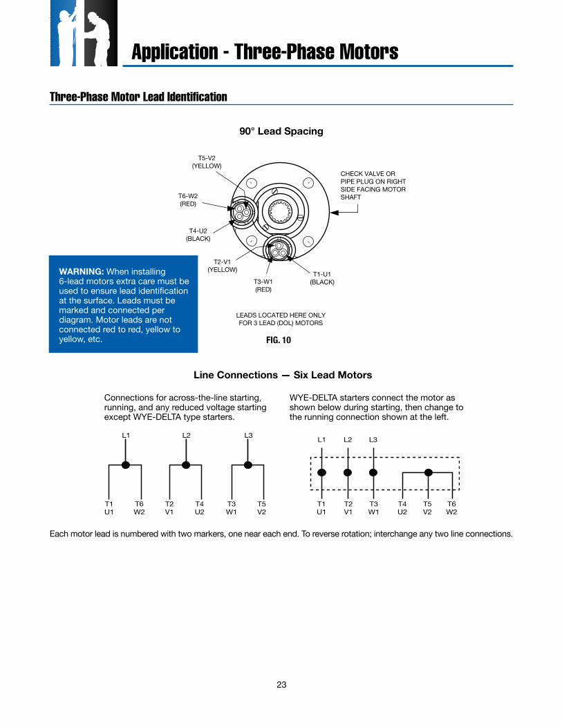
23
Three-Phase Motor Lead Identification
T5-V2(YELLOW)
T2-V1(YELLOW)
T4-U2(BLACK)
T1-U1(BLACK)
T6-W2(RED)
T3-W1(RED)
LEADS LOCATED HERE ONLYFOR 3 LEAD (DOL) MOTORS
CHECK VALVE OR PIPE PLUG ON RIGHTSIDE FACING MOTORSHAFT
90° Lead Spacing
Connections for across-the-line starting, running, and any reduced voltage starting except WYE-DELTA type starters.
WYE-DELTA starters connect the motor as shown below during starting, then change to the running connection shown at the left.
Line Connections — Six Lead Motors
Each motor lead is numbered with two markers, one near each end. To reverse rotation; interchange any two line connections.
L1
T1U1
T1U1
T6W2
T6W2
L2
T2V1
T2V1
T4U2
T4U2
L3 L1 L2 L3
T3W1
T3W1
T5V2
T5V2
Application - Three-Phase Motors
WARNING: When installing 6-lead motors extra care must be used to ensure lead identification at the surface. Leads must be marked and connected per diagram. Motor leads are not connected red to red, yellow to yellow, etc. FIG. 10
24
Reduced Voltage Starters
Inline Booster Pump Systems
Application - Three-Phase Motors
Franklin Electric offers three different types of motors for non-vertical applications.1. The booster motors are specifically designed for
booster applications. They are the “Best Choice” for sealed reverse osmosis applications. These motors are the result of two years of focused development and bring additional value and durability to booster module systems. These motors are only available to OEMs or distributors who have demonstrated capability in booster module systems design and operation and adhere to Franklin’s Application Manual requirements.
2. The Hi-Temp motors have many of the internal design features of the booster motor. It’s additional length allows for higher temperature handling and the Sand Fighter sealing system provides greater abrasion resistance. One or both of these conditions
are often experienced in open atmosphere applications such as lakes, ponds, etc.
3. The Standard Vertical Water Well (30-93 kW) motors can be adapted to non-vertical applications when applied per the below guidelines. However, they will be more sensitive to application variances than the other two designs.
All of the above motors must be applied per the guidelines listed below. In addition, for all applications where the motor is applied in a sealed system, a Submersible Motor Booster Installation Record (Form 3655) or its equivalent must be completed at startup and received by Franklin Electric within 60 days. A sealed system is one where the motor and pump intake are mounted in a sleeve and the water feeding the pump intake is not open to the atmosphere.
Continued on next page
All Franklin three-phase submersible motors are suitable for full-voltage starting. Under this condition the motor speed goes from zero to full speed within a half second or less. The motor current goes from zero to locked rotor amps, then drops to running amps at full speed. This may dim lights, cause momentary voltage dips to other electrical equipment, and shock power distribution transformers.In some cases the power companies may require reduced-voltage starters to limit this voltage dip. There are also times when reduced-voltage starters may be desirable to reduce motor starting torque thus reducing the stress on shafts, couplings, and discharge piping. Reduced-voltage starters also slow the rapid acceleration of the water on start-up to help control upthrust and water hammer.Reduced-voltage starters may not be required if the maximum recommended cable length is used. With maximum recommended cable length there is a 5% voltage drop in the cable at running amps, resulting in about 20% reduction in starting current and about 36% reduction in starting torque compared to having rated voltage at the motor. This may be enough reduction in starting current so that reduced-voltage starters are not required.Three-Lead Motors: Autotransformer or solid-state reduced-voltage starters may be used for soft-starting standard three-phase motors. When autotransformer starters are used, the motor should be supplied with at least 55% of rated voltage to ensure adequate starting torque. Most autotransformer starters have 65% and 80% taps. Setting the taps on these starters depends on the percentage of the maximum allowable cable length used in the system.
If the cable length is less than 50% of the maximum allowable, either the 65% or the 80% taps may be used. When the cable length is more than 50% of allowable, the 80% tap should be used. Six-Lead Motors: Wye-Delta starters are used with six-lead Wye-Delta motors. All Franklin 6" and 8" three-phase motors are available in six-lead Wye-Delta construction. Consult the factory for details and availability. Part winding starters are not compatible with Franklin Electric submersible motors and should not be used. Wye-Delta starters of the open-transition type, which momentarily interrupt power during the starting cycle, are not recommended. Closed-transition starters have no interruption of power during the start cycle and can be used with satisfactory results. Reduced-voltage starters have adjustable settings for acceleration ramp time, typically preset at 30 seconds. They must be adjusted so the motor is at full voltage within THREE SECONDS MAXIMUM to prevent excessive radial and thrust bearing wear.If Subtrol-Plus or SubMonitor is used the acceleration time must be set to TWO SECONDS MAXIMUM due to the 3 second reaction time of the Subtrol-Plus or SubMonitor.Solid-state starters AkA soft starts may not be compatible with Subtrol-Plus/SubMonitor. However, in some cases a bypass contactor has been used. Consult the factory for details.During shutdown, Franklin Electric’s recommendation is for the power to be removed, allowing the pump/motor to coast down. Stopping the motor by ramping down the voltage is possible, but should be limited to three (3) seconds maximum.
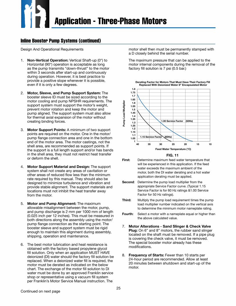
25
Inline Booster Pump Systems (continued)
Application - Three-Phase Motors
Design And Operational Requirements
1. Non-Vertical Operation: Vertical Shaft-up (0°) to Horizontal (90°) operation is acceptable as long as the pump transmits “down-thrust” to the motor within 3 seconds after start-up and continuously during operation. However, it is best practice to provide a positive slope whenever it is possible, even if it is only a few degrees.
2. Motor, Sleeve, and Pump Support System: The booster sleeve ID must be sized according to the motor cooling and pump NPSHR requirements. The support system must support the motor’s weight, prevent motor rotation and keep the motor and pump aligned. The support system must also allow for thermal axial expansion of the motor without creating binding forces.
3. Motor Support Points: A minimum of two support points are required on the motor. One in the motor/pump flange connection area and one in the bottom end of the motor area. The motor castings, not the shell area, are recommended as support points. If the support is a full length support and/or has bands in the shell area, they must not restrict heat transfer or deform the shell.
4. Motor Support Material and Design: The support system shall not create any areas of cavitation or other areas of reduced flow less than the minimum rate required by this manual. They should also be designed to minimize turbulence and vibration and provide stable alignment. The support materials and locations must not inhibit the heat transfer away from the motor.
5. Motor and Pump Alignment: The maximum allowable misalignment between the motor, pump, and pump discharge is 2 mm per 1000 mm of length (0.025 inch per 12 inches). This must be measured in both directions along the assembly using the motor/pump flange connection as the starting point. The booster sleeve and support system must be rigid enough to maintain this alignment during assembly, shipping, operation and maintenance.
6. The best motor lubrication and heat resistance is obtained with the factory based propylene glycol fill solution. Only when an application MUST HAVE deionized (DI) water should the factory fill solution be replaced. When a deionized water fill is required, the motor must be derated as indicated on the below chart. The exchange of the motor fill solution to DI water must be done by an approved Franklin service shop or representative using a vacuum fill system per Franklin’s Motor Service Manual instruction. The
motor shell then must be permanently stamped with a D closely behind the serial number.
The maximum pressure that can be applied to the motor internal components during the removal of the factory fill solution is 7 psi (0.5 bar.)
First: Determine maximum feed water temperature that will be experienced in this application. If the feed water exceeds the maximum ambient of the motor, both the DI water derating and a hot water application derating must be applied.
Second: Determine the pump load multiplier from the appropriate Service Factor curve. (Typical 1.15 Service Factor is for 60 Hz ratings &1.00 Service Factor for 50 Hz ratings).
Third: Multiply the pump load requirement times the pump load multiplier number indicated on the vertical axis to determine the minimum motor nameplate rating.
Fourth: Select a motor with a nameplate equal or higher than the above calculated value.
7. Motor Alterations - Sand Slinger & Check Valve Plug: On 6” and 8” motors, the rubber sand slinger located on the shaft must be removed. If a pipe plug is covering the check valve, it must be removed. The special booster motor already has these modifications.
8. Frequency of Starts: Fewer than 10 starts per 24-hour period are recommended. Allow at least 20 minutes between shutdown and start-up of the motor.
FIG. 11
1.8
1.7
1.6
1.5
1.4
1.3
1.2
1.1
130 25 20 15 103540
1.75
1.65
1.55
1.45
1.35
1.25
1.15
1.05
1.00 Service Factor (50Hz)
1.15 Service Factor (60Hz)
Derating Factor for Motors That Must Have Their Factory Fill Replaced With Deionized Water 8" Encapsulated Motor
Feed Water Temperature (°C)
Pum
p L
oad
Mul
tip
lier
Continued on next page
26
Cable Temp. Rating (°C)
Motor Nameplate Rated Amps Full Load
6mm2 10mm2 16mm2 25mm2 35mm2
#10 AWG #8 AWG #6 AWG #4 AWG #2 AWG
In Air In Conduit In Air In Conduit In Air In Conduit In Air In Conduit In Air In Conduit
753-LEAD (DOL) 40A 28A 56A 40A 76A 52A 100A 68A 136A 92A6-LEAD (Y-∆) 69A 48A 97A 69A 132A 90A 173A 118A 236A 159A
903-LEAD (DOL) 44A 32A 64A 44A 84A 60A 112A 76A 152A 104A6-LEAD (Y-∆) 76A 55A 111A 76A 145A 104A 194A 132A 263A 180A
1253-LEAD (DOL) 66A 46A 77A 53A 109A 75A 153A 105A 195A 134A6-LEAD (Y-∆) 114A 80A 133A 91A 188A 130A 265A 181A 337A 232A
Inline Booster Pump Systems (continued)
Application - Three-Phase Motors
9. Controls-Soft Starters and VFDs: Reduced voltage starters and variable speed drives (inverter drives) may be used with Franklin three-phase submersible motors to reduce starting current, upthrust, and mechanical stress during start-up. The guidelines for their use with submersible motors are different than with normal air cooled motor applications. Refer to the Franklin Electric Application, Installation and Maintenance (AIM) Manual, Reduced Voltage Starters section or Variable Speed Submersible Pump Operation, Inverter Drives sections for specific details including required filtering.
10. Motor Overload Protection: Submersible motors require properly sized ambient compensated Class 10 quick-trip overloads per Franklin’s AIM Manual guidelines to protect the motor. Class 20 or higher overloads are NOT acceptable. Franklin’s SubMonitor is strongly recommended for all large submersibles since it is capable of sensing motor heat without any additional wiring to the motor. Applications using soft starters with a SubMonitor require a start-up bypass - consult the factory for details. SubMonitor can not be used in applications using a VFD control.
11. Motor Surge Protection: Properly sized, grounded and dedicated motor surge arrestors must be installed in the supply line of the booster module as close to the motor as possible. This is required on all systems including those using soft-starters and variable speed drives (inverter drives).
12. Wiring: Franklin’s lead assemblies are only sized for submerged operation in water to the motor nameplate maximum ambient temperature and may overheat and cause failure or serious injury if operated in air. Any wiring not submerged must meet applicable national and local wiring codes and Franklin cable chart tables 8-9. (Notice: wire size, wire rating and insulation temperature rating must be
known when determining its suitability to operate in air or conduit. Typically, for a given size and rating, as the insulation temperature rating increases its ability to operate in air or conduit also increases.)
13. Check Valves: Spring-loaded check valves must be used on start-up to minimize motor upthrusting, water hammer, or in multiple booster (parallel) applications to prevent reverse flow.
14. Pressure Relief Valves: A pressure relief valve is required and must be selected to ensure that, as the pump approaches shut-off, it never reaches the point that the motor will not have adequate cooling flow past it.
15. System Purge (Can Flooding): An air bleeder valve must be installed on the booster sleeve so that flooding may be accomplished prior to booster start-up. Once flooding is complete, the booster should be started and brought up to operating pressure as quickly as possible to minimize the duration of an upthrust condition. At no time should air be allowed to gather in the booster sleeve because this will prevent proper cooling of the motor and permanently damage it.
16. System Flush – Must Not Spin Pump: Applications may utilize a low flow flushing operation. Flow through the booster sleeve must not spin the pump impellers and the motor shaft. If spinning takes place, the bearing system will be permanently damaged and the motor life shortened. Consult the booster pump manufacturer for maximum flow rate through the pump when the motor is not energized.
Based on 30 °C maximum ambient with cable length of 100 feet or less.
Table 14 Franklin Cable chart (See 12. Wiring)
Continued on next page
27
Application - Three-Phase Motors
17. Open Atmosphere Booster Pump Systems: When an open booster is placed in a lake, tank, etc. that is open to atmospheric pressure, the water level must provide sufficient head pressure to allow the pump to operate above its NPSHR requirement at all times and all seasons. Adequate inlet pressure must be provided prior to booster start-up.
Four Continuous Monitoring System Requirements for Sealed Booster Systems.
1. Water Temperature: Feed water on each booster must be continuously monitored and not allowed to exceed the motor nameplate maximum ambient temperature at any time. IF THE INLET TEMPERATURE EXCEEDS THE MOTOR NAMEPLATE MAXIMUM AMBIENT TEMPERATURE, THE SYSTEM MUST SHUTDOWN IMMEDIATELY TO PREVENT PERMANENT MOTOR DAMAGE. If feed water temperatures are expected to be above the allowable temperature, the motor must be derated. See Franklin’s AIM Manual, Hot Water Applications section for derating guidelines. (The high temperature feed water derating is in addition to the exchange to DI water derating if the motor factory fill solution was exchanged to DI water.)
2. Inlet Pressure: The inlet pressure on each booster module must be continuously monitored. It must always be positive and higher than the NPSHR (Net Positive Suction Head Requirement) of the pump. A minimum of 20 PSIG (1.38 Bar) is required at all times, except for 10 seconds or less when the motor is starting and the system is coming up to pressure. Even during these 10 seconds the pressure must remain positive and be higher than the NPSHR (Net Positive Suction Head Requirement) of the pump.
PSIG is the actual value displayed on a pressure gauge in the system piping. PSIG is the pressure above the atmospheric conditions. If at any time these pressure requirements are not being met, the motor must be de-energized immediately to prevent permanent damage to the motor. Once the motor is damaged, it is usually not immediately noticeable, but progresses and results in a premature motor failure weeks or months after the damage occurred. Motors that will be exposed to pressure in excess of 500 psi (34.47 Bar) must undergo special high pressure testing. Consult factory for details and availability.
3. Discharge Flow: The flow rate for each pump must not be allowed to drop below the motor minimum cooling flow requirement. IF THE MOTOR MINIMUM COOLING FLOW REQUIREMENT IS NOT BEING MET FOR MORE THAN 10 SECONDS, THE SYSTEM MUST BE SHUT DOWN IMMEDIATELY TO PREVENT PERMANENT MOTOR DAMAGE.
4. Discharge Pressure: The discharge pressure must be monitored to ensure that a downthrust load toward the motor is present within 3 seconds after start-up and continuously during operation. IF THE MOTOR DISCHARGE PRESSURE IS NOT ADEQUATE TO MEET THIS REQUIREMENT, THE SYSTEM MUST BE SHUT DOWN IMMEDIATELY TO PREVENT PERMANENT MOTOR DAMAGE.
Inline Booster Pump Systems (continued)
28
Variable Speed Submersible Pump Operation, Inverter Drives
Application - Three-Phase Motors
Franklin three-phase submersible motors are operable from variable frequency inverter drives when applied within guidelines shown below. These guidelines are based on present Franklin information for inverter drives, lab tests and actual installations, and must be followed for warranty to apply to inverter drive installations. Franklin two-wire and three-wire single-phase submersible motors are not recommended for variable speed operation.
Load Capability: Pump load should not exceed motor nameplate service factor amps at rated voltage and frequency.Frequency Range: Continuous between 30 Hz and rated frequency (50 or 60 Hz). Operations above rated frequency require special considerations, consult factory for details.Volts/Hz: Use motor nameplate volts and frequency for the drive base settings. Many drives have means to increase efficiency at reduced pump speeds by lowering motor voltage. This is the preferred operating mode.Voltage Rise-time or dV/dt: Limit the peak voltage to the motor to 1000V and keep the rise-time greater than 2 µsec. Alternately stated: keep dV/dt < 500V/µsec. See Filters or Reactors. Motor Current Limits: Load no higher than motor nameplate service factor amps. For 50 Hz ratings, nameplate maximum amps are rated amps. See Overload Protection below.Motor Overload Protection: Protection in the drive (or separately furnished) must be set to trip within 10 seconds at 5 times motor maximum nameplate amps in any line, and ultimately trip within 115% of nameplate maximum amps in any line.
WARNING: There is a potential shock hazard from contact with insulated cables from a PWM drive to the motor. This hazard is due to high frequency voltage content of a PWM drive output.
Subtrol-Plus: Franklin’s Subtrol-Plus protection systems ARE NOT USABLE on VFD installations. Start and Stop: One second maximum ramp-up and ramp-down times between stopped and 30 Hz. Stopping by coast-down is preferable. Successive Starts: Allow 60 seconds before restarting.Filters or Reactors: Required if all three of the following conditions are met: (1) Voltage is 380 or greater and (2) Drive uses IGBT or BJT switches (rise-times < 2 µsec) and (3) Cable from drive to motor is more than 15.2 m. A low-pass filter is preferable. Filters or reactors should be selected in conjunction with the drive manufacturer and must be specifically designed for VFD operation.Cable Lengths: Per Franklin’s cable tables unless a reactor is used. If a long cable is used with a reactor, additional voltage drop will occur between the VFD and the motor. To compensate, set the VFD output voltage higher than the motor rating in proportion to the reactor impedance (102% voltage for 2% impedance, etc.). Motor Cooling Flow: For installations that are variable-flow, variable-pressure, minimum flow rates must be maintained at nameplate frequency. In variable-flow, constant pressure installations, minimum flow rates must be maintained at the lowest flow condition. Franklin’s minimum flow requirements for 4” motors : 7.26 cm/sec. and for 6” and 8” motors: 15.24 cm/sec.Carrier Frequency: Applicable to PWM drives only. These drives often allow selection of the carrier frequency. Use a carrier frequency at the low end of the available range.Miscellaneous: Franklin three-phase motors are not declared “Inverter Duty” motors per NEMA MG1, Part 31 standards. However, Franklin’s submersible motors can be used with VFDs without problems and/or warranty concerns provided these guidelines are followed.
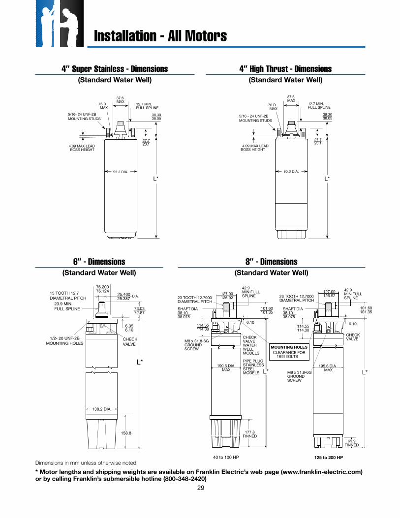
29
4” Super Stainless - Dimensions(Standard Water Well)
4” High Thrust - Dimensions(Standard Water Well)
38.3038.05
37.6MAX.76 R
MAX
27.723.1
L*
4.09 MAX LEADBOSS HEIGHT
95.3 DIA.
12.7 MIN.FULL SPLINE
5/16- 24 UNF-2BMOUNTING STUDS
38.3038.05
37.6MAX
.76 RMAX
L*
4.09 MAX LEADBOSS HEIGHT
95.3 DIA.
12.7 MIN.FULL SPLINE
27.723.1
5/16 - 24 UNF-2BMOUNTING STUDS
L*
138.2 DIA.
6.356.10
76.20076.124
25.40025.387 DIA.
23.9 MIN. FULL SPLINE 73.03
72.87
158.8
CHECKVALVE
15 TOOTH 12.7DIAMETRAL PITCH
1/2- 20 UNF-2BMOUNTING HOLES
40 to 100 HP
127.00126.92
114.55114.30
42.9MIN FULLSPLINE
6.10
23 TOOTH 12.7000DIAMETRAL PITCH
CHECK VALVE WATERWELL MODELS
PIPE PLUG STAINLESSSTEEL MODELS
M8 x 31.8-6GGROUNDSCREW
190.5 DIA MAX
177.8FINNED
101.60101.35
L*
23 TOOTH 12.7000DIAMETRAL PITCH
SHAFT DIA38.1038.075
SHAFT DIA38.1038.075
114.55114.30
M8 x 31.8-6GGROUNDSCREW
69.9FINNED
101.60101.35
L*
125 to 200 HP
127.00126.92
42.9MIN FULLSPLINE
6.10
CHECK VALVE
195.6 DIA MAX
MOUNTING HOLESCLEARANCE FOR
16 OLTS
6” - Dimensions 8” - Dimensions(Standard Water Well)(Standard Water Well)
* Motor lengths and shipping weights are available on Franklin Electric’s web page (www.franklin-electric.com) or by calling Franklin’s submersible hotline (800-348-2420)
Installation - All Motors
Dimensions in mm unless otherwise noted
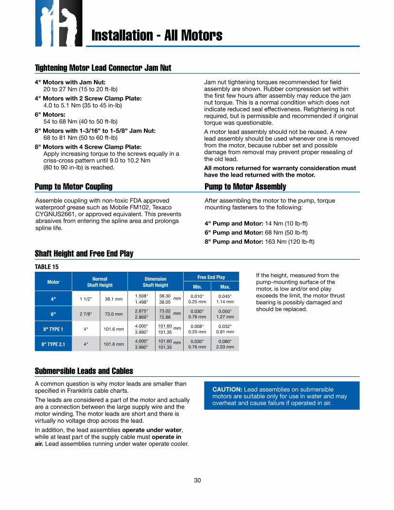
30
Tightening Motor Lead Connector Jam nut
Pump to Motor Coupling
Shaft Height and Free End Play
Submersible Leads and Cables
Installation - All Motors
TABLE 15
4" Motors with Jam Nut: 20 to 27 Nm (15 to 20 ft-lb)4" Motors with 2 Screw Clamp Plate: 4.0 to 5.1 Nm (35 to 45 in-lb)6" Motors: 54 to 68 Nm (40 to 50 ft-lb)8" Motors with 1-3/16" to 1-5/8" Jam Nut: 68 to 81 Nm (50 to 60 ft-lb) 8" Motors with 4 Screw Clamp Plate: Apply increasing torque to the screws equally in a
criss-cross pattern until 9.0 to 10.2 Nm (80 to 90 in-lb) is reached.
Jam nut tightening torques recommended for field assembly are shown. Rubber compression set within the first few hours after assembly may reduce the jam nut torque. This is a normal condition which does not indicate reduced seal effectiveness. Retightening is not required, but is permissible and recommended if original torque was questionable.A motor lead assembly should not be reused. A new lead assembly should be used whenever one is removed from the motor, because rubber set and possible damage from removal may prevent proper resealing of the old lead.All motors returned for warranty consideration must have the lead returned with the motor.
Assemble coupling with non-toxic FDA approved waterproof grease such as Mobile FM102, Texaco CYGNUS2661, or approved equivalent. This prevents abrasives from entering the spline area and prolongs spline life.
After assembling the motor to the pump, torque mounting fasteners to the following:
4" Pump and Motor: 14 Nm (10 lb-ft)6" Pump and Motor: 68 Nm (50 lb-ft)8" Pump and Motor: 163 Nm (120 lb-ft)
Pump to Motor Assembly
If the height, measured from the pump-mounting surface of the motor, is low and/or end play exceeds the limit, the motor thrust bearing is possibly damaged and should be replaced.
Motor Normal Shaft Height
DimensionShaft Height
Free End Play
Min. Max.
4" 1 1/2" 38.1 mm 1.508" 1.498"
38.3038.05
0.010"0.25 mm
0.045"1.14 mm
6" 2 7/8" 73.0 mm 2.875"2.869"
73.0272.88
0.030"0.76 mm
0.050"1.27 mm
8" TYPE 1 4" 101.6 mm 4.000"3.990"
101.60101.35
0.008"0.20 mm
0.032"0.81 mm
8" TYPE 2.1 4" 101.6 mm 4.000"3.990"
101.60101.35
0.030"0.76 mm
0.080"2.03 mm
mm
mm
mm
mm
A common question is why motor leads are smaller than specified in Franklin’s cable charts.
The leads are considered a part of the motor and actually are a connection between the large supply wire and the motor winding. The motor leads are short and there is virtually no voltage drop across the lead.
In addition, the lead assemblies operate under water, while at least part of the supply cable must operate in air. Lead assemblies running under water operate cooler.
CAUTION: Lead assemblies on submersible motors are suitable only for use in water and may overheat and cause failure if operated in air.
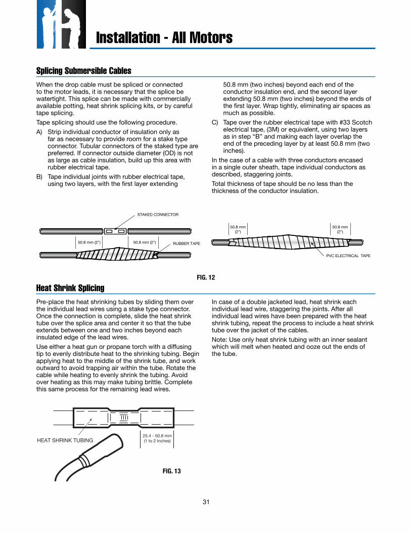
31
When the drop cable must be spliced or connected to the motor leads, it is necessary that the splice be watertight. This splice can be made with commercially available potting, heat shrink splicing kits, or by careful tape splicing.Tape splicing should use the following procedure.A) Strip individual conductor of insulation only as
far as necessary to provide room for a stake type connector. Tubular connectors of the staked type are preferred. If connector outside diameter (OD) is not as large as cable insulation, build up this area with rubber electrical tape.
B) Tape individual joints with rubber electrical tape, using two layers, with the first layer extending
50.8 mm (two inches) beyond each end of the conductor insulation end, and the second layer extending 50.8 mm (two inches) beyond the ends of the first layer. Wrap tightly, eliminating air spaces as much as possible.
C) Tape over the rubber electrical tape with #33 Scotch electrical tape, (3M) or equivalent, using two layers as in step “B” and making each layer overlap the end of the preceding layer by at least 50.8 mm (two inches).
In the case of a cable with three conductors encased in a single outer sheath, tape individual conductors as described, staggering joints.Total thickness of tape should be no less than the thickness of the conductor insulation.
Splicing Submersible Cables
STAKED CONNECTOR
RUBBER TAPE50.8 mm (2")
PVC ELECTRICAL TAPE
50.8 mm(2")
50.8 mm(2")
50.8 mm (2")
FIG. 12
Installation - All Motors
Pre-place the heat shrinking tubes by sliding them over the individual lead wires using a stake type connector. Once the connection is complete, slide the heat shrink tube over the splice area and center it so that the tube extends between one and two inches beyond each insulated edge of the lead wires.Use either a heat gun or propane torch with a diffusing tip to evenly distribute heat to the shrinking tubing. Begin applying heat to the middle of the shrink tube, and work outward to avoid trapping air within the tube. Rotate the cable while heating to evenly shrink the tubing. Avoid over heating as this may make tubing brittle. Complete this same process for the remaining lead wires.
Heat Shrink Splicing
HEAT SHRINK TUBING25.4 - 50.8 mm(1 to 2 Inches)
FIG. 13
In case of a double jacketed lead, heat shrink each individual lead wire, staggering the joints. After all individual lead wires have been prepared with the heat shrink tubing, repeat the process to include a heat shrink tube over the jacket of the cables.Note: Use only heat shrink tubing with an inner sealant which will melt when heated and ooze out the ends of the tube.
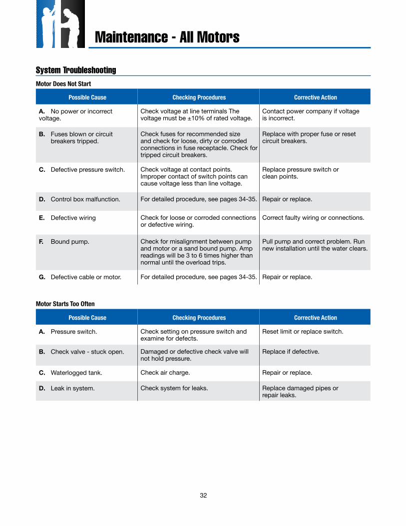
32
Maintenance - All Motors
System TroubleshootingMotor Does Not Start
Possible Cause Checking Procedures Corrective Action
A. No power or incorrect voltage.
Check voltage at line terminals The voltage must be ±10% of rated voltage.
Contact power company if voltage is incorrect.
B. Fuses blown or circuit breakers tripped.
Check fuses for recommended size and check for loose, dirty or corroded connections in fuse receptacle. Check for tripped circuit breakers.
Replace with proper fuse or reset circuit breakers.
C. Defective pressure switch. Check voltage at contact points. Improper contact of switch points can cause voltage less than line voltage.
Replace pressure switch or clean points.
D. Control box malfunction. For detailed procedure, see pages 34-35. Repair or replace.
E. Defective wiring Check for loose or corroded connections or defective wiring.
Correct faulty wiring or connections.
F. Bound pump. Check for misalignment between pump and motor or a sand bound pump. Amp readings will be 3 to 6 times higher than normal until the overload trips.
Pull pump and correct problem. Run new installation until the water clears.
G. Defective cable or motor. For detailed procedure, see pages 34-35. Repair or replace.
Motor Starts Too Often
Possible Cause Checking Procedures Corrective Action
A. Pressure switch. Check setting on pressure switch and examine for defects.
Reset limit or replace switch.
B. Check valve - stuck open. Damaged or defective check valve will not hold pressure.
Replace if defective.
C. Waterlogged tank. Check air charge. Repair or replace.
D. Leak in system. Check system for leaks. Replace damaged pipes or repair leaks.
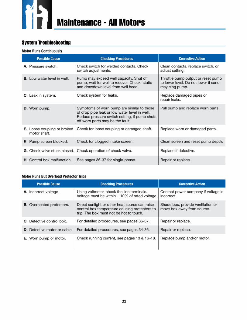
33
Possible Cause Checking Procedures Corrective Action
A. Pressure switch. Check switch for welded contacts. Check switch adjustments.
Clean contacts, replace switch, or adjust setting.
B. Low water level in well. Pump may exceed well capacity. Shut off pump, wait for well to recover. Check static and drawdown level from well head.
Throttle pump output or reset pump to lower level. Do not lower if sand may clog pump.
C. Leak in system. Check system for leaks. Replace damaged pipes or repair leaks.
D. Worn pump. Symptoms of worn pump are similar to those of drop pipe leak or low water level in well. Reduce pressure switch setting, if pump shuts off worn parts may be the fault.
Pull pump and replace worn parts.
E. Loose coupling or broken motor shaft.
Check for loose coupling or damaged shaft. Replace worn or damaged parts.
F. Pump screen blocked. Check for clogged intake screen. Clean screen and reset pump depth.
G. Check valve stuck closed. Check operation of check valve. Replace if defective.
H. Control box malfunction. See pages 36-37 for single-phase. Repair or replace.
Motor Runs But Overload Protector Trips
Possible Cause Checking Procedures Corrective Action
A. Incorrect voltage. Using voltmeter, check the line terminals. Voltage must be within ± 10% of rated voltage.
Contact power company if voltage is incorrect.
B. Overheated protectors. Direct sunlight or other heat source can raise control box temperature causing protectors to trip. The box must not be hot to touch.
Shade box, provide ventilation or move box away from source.
C. Defective control box. For detailed procedures, see pages 36-37. Repair or replace.
D. Defective motor or cable. For detailed procedures, see pages 34-36. Repair or replace.
E. Worn pump or motor. Check running current, see pages 13 & 16-18. Replace pump and/or motor.
System TroubleshootingMotor Runs Continuously
Maintenance - All Motors
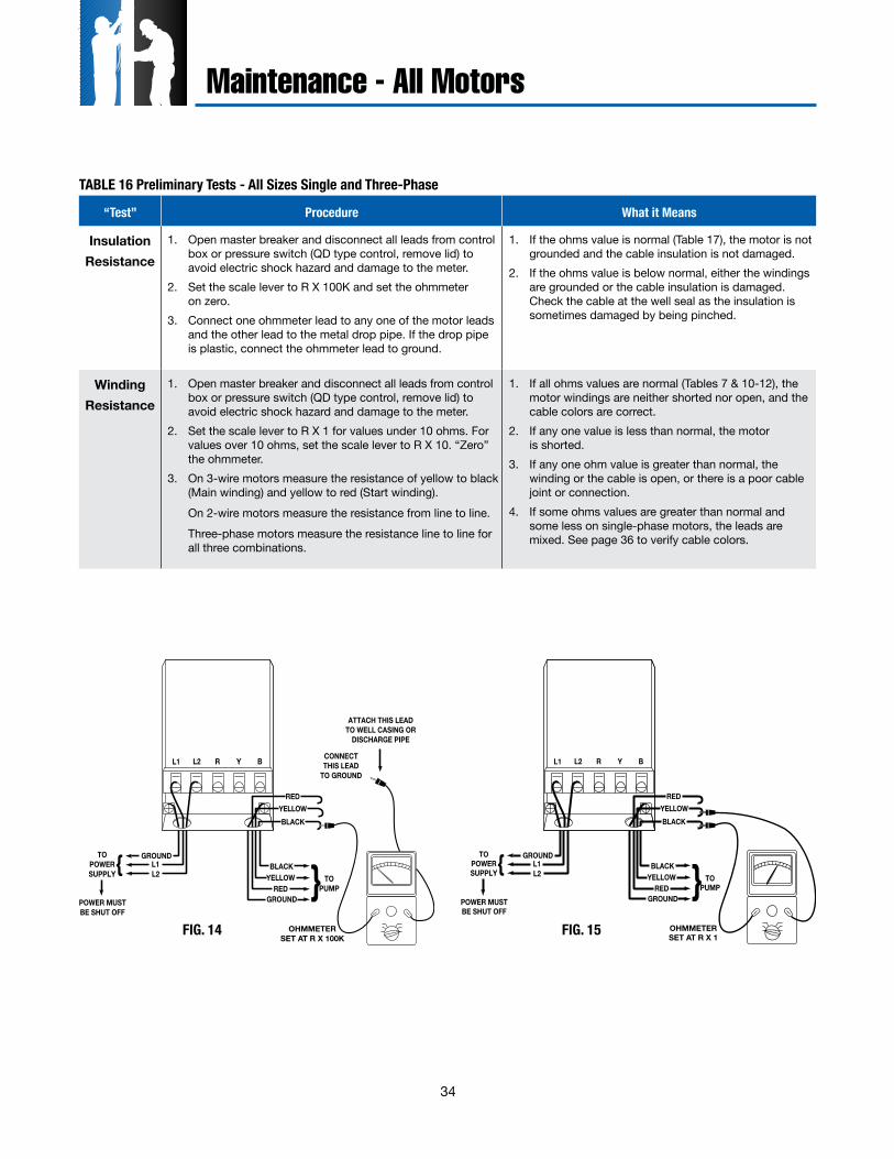
34
“Test” Procedure What it Means
Insulation Resistance
1. Open master breaker and disconnect all leads from control box or pressure switch (QD type control, remove lid) to avoid electric shock hazard and damage to the meter.
2. Set the scale lever to R X 100K and set the ohmmeter on zero.
3. Connect one ohmmeter lead to any one of the motor leads and the other lead to the metal drop pipe. If the drop pipe is plastic, connect the ohmmeter lead to ground.
1. If the ohms value is normal (Table 17), the motor is not grounded and the cable insulation is not damaged.
2. If the ohms value is below normal, either the windings are grounded or the cable insulation is damaged. Check the cable at the well seal as the insulation is sometimes damaged by being pinched.
WindingResistance
1. Open master breaker and disconnect all leads from control box or pressure switch (QD type control, remove lid) to avoid electric shock hazard and damage to the meter.
2. Set the scale lever to R X 1 for values under 10 ohms. For values over 10 ohms, set the scale lever to R X 10. “Zero” the ohmmeter.
3. On 3-wire motors measure the resistance of yellow to black (Main winding) and yellow to red (Start winding).
On 2-wire motors measure the resistance from line to line. Three-phase motors measure the resistance line to line for
all three combinations.
1. If all ohms values are normal (Tables 7 & 10-12), the motor windings are neither shorted nor open, and the cable colors are correct.
2. If any one value is less than normal, the motor is shorted.
3. If any one ohm value is greater than normal, the winding or the cable is open, or there is a poor cable joint or connection.
4. If some ohms values are greater than normal and some less on single-phase motors, the leads are mixed. See page 36 to verify cable colors.
TABLE 16 Preliminary Tests - All Sizes Single and Three-Phase
GROUND
L2{TOPOWERSUPPLY
BLACK {YELLOWRED
GROUNDPOWER MUSTBE SHUT OFF
BLACKYELLOW
RED
L1 L2 R Y B
L1
TOPUMP
OHMMETERSET AT R X 100K
CONNECTTHIS LEAD
TO GROUND
ATTACH THIS LEADTO WELL CASING OR
DISCHARGE PIPE
GROUND
L2{TOPOWERSUPPLY
BLACK {YELLOWRED
GROUNDPOWER MUSTBE SHUT OFF
BLACKYELLOW
RED
L1 L2 R Y B
L1
TOPUMP
OHMMETERSET AT R X 1
FIG. 14 FIG. 15
Maintenance - All Motors
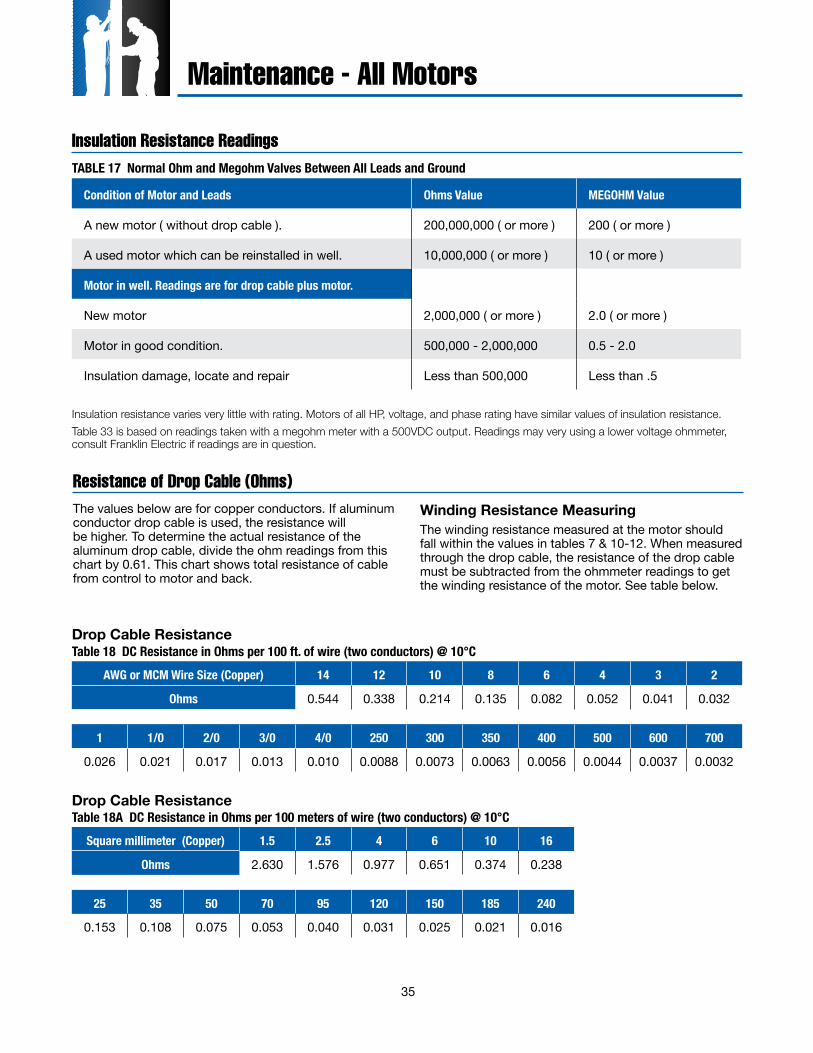
35
Condition of Motor and Leads Ohms Value MEGOHM Value
A new motor ( without drop cable ). 200,000,000 ( or more ) 200 ( or more )
A used motor which can be reinstalled in well. 10,000,000 ( or more ) 10 ( or more )
Motor in well. Readings are for drop cable plus motor.
New motor 2,000,000 ( or more ) 2.0 ( or more )
Motor in good condition. 500,000 - 2,000,000 0.5 - 2.0
Insulation damage, locate and repair Less than 500,000 Less than .5
Insulation Resistance ReadingsTABLE 17 Normal Ohm and Megohm Valves Between All Leads and Ground
Insulation resistance varies very little with rating. Motors of all HP, voltage, and phase rating have similar values of insulation resistance.Table 33 is based on readings taken with a megohm meter with a 500VDC output. Readings may very using a lower voltage ohmmeter, consult Franklin Electric if readings are in question.
The values below are for copper conductors. If aluminum conductor drop cable is used, the resistance will be higher. To determine the actual resistance of the aluminum drop cable, divide the ohm readings from this chart by 0.61. This chart shows total resistance of cable from control to motor and back.
Winding Resistance MeasuringThe winding resistance measured at the motor should fall within the values in tables 7 & 10-12. When measured through the drop cable, the resistance of the drop cable must be subtracted from the ohmmeter readings to get the winding resistance of the motor. See table below.
Resistance of Drop Cable (Ohms)
AWG or MCM Wire Size (Copper) 14 12 10 8 6 4 3 2
Ohms 0.544 0.338 0.214 0.135 0.082 0.052 0.041 0.032
1 1/0 2/0 3/0 4/0 250 300 350 400 500 600 700
0.026 0.021 0.017 0.013 0.010 0.0088 0.0073 0.0063 0.0056 0.0044 0.0037 0.0032
Square millimeter (Copper) 1.5 2.5 4 6 10 16
Ohms 2.630 1.576 0.977 0.651 0.374 0.238
25 35 50 70 95 120 150 185 240
0.153 0.108 0.075 0.053 0.040 0.031 0.025 0.021 0.016
Table 18 DC Resistance in Ohms per 100 ft. of wire (two conductors) @ 10°C
Table 18A DC Resistance in Ohms per 100 meters of wire (two conductors) @ 10°CDrop Cable Resistance
Drop Cable Resistance
Maintenance - All Motors
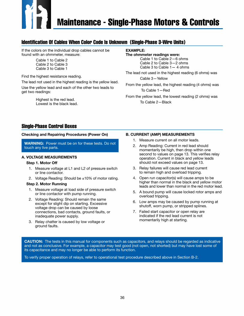
36
If the colors on the individual drop cables cannot be found with an ohmmeter, measure: Cable 1 to Cable 2 Cable 2 to Cable 3 Cable 3 to Cable 1
Find the highest resistance reading.The lead not used in the highest reading is the yellow lead.Use the yellow lead and each of the other two leads to get two readings:
Highest is the red lead. Lowest is the black lead.
EXAMPLE:The ohmmeter readings were: Cable 1 to Cable 2—6 ohms Cable 2 to Cable 3—2 ohms Cable 3 to Cable 1— 4 ohmsThe lead not used in the highest reading (6 ohms) was Cable 3—YellowFrom the yellow lead, the highest reading (4 ohms) was To Cable 1—Red From the yellow lead, the lowest reading (2 ohms) was To Cable 2—Black
Identification Of Cables When Color Code Is Unknown (Single-Phase 3-Wire Units)
A. VOLTAGE MEASUREMENTS Step 1. Motor Off 1. Measure voltage at L1 and L2 of pressure switch
or line contactor. 2. Voltage Reading: Should be ±10% of motor rating. Step 2. Motor Running 1. Measure voltage at load side of pressure switch
or line contactor with pump running. 2. Voltage Reading: Should remain the same
except for slight dip on starting. Excessive voltage drop can be caused by loose connections, bad contacts, ground faults, or inadequate power supply.
3. Relay chatter is caused by low voltage or ground faults.
B. CURRENT (AMP) MEASUREMENTS 1. Measure current on all motor leads. 2. Amp Reading: Current in red lead should
momentarily be high, then drop within one second to values on page 13. This verifies relay operation. Current in black and yellow leads should not exceed values on page 13.
3. Relay failures will cause red lead current to remain high and overload tripping.
4. Open run capacitor(s) will cause amps to be higher than normal in the black and yellow motor leads and lower than normal in the red motor lead.
5. A bound pump will cause locked rotor amps and overload tripping.
6. Low amps may be caused by pump running at shutoff, worn pump, or stripped splines.
7. Failed start capacitor or open relay are indicated if the red lead current is not momentarily high at starting.
Single-Phase Control BoxesChecking and Repairing Procedures (Power On)
WARNING: Power must be on for these tests. Do not touch any live parts.
CAUTION: The tests in this manual for components such as capacitors, and relays should be regarded as indicative and not as conclusive. For example, a capacitor may test good (not open, not shorted) but may have lost some of its capacitance and may no longer be able to perform its function.
To verify proper operation of relays, refer to operational test procedure described above in Section B-2.
Maintenance - Single-Phase Motors & Controls
37
QD Control Box (Power Off)A. START CAPACITOR 1. Meter Setting: R x 1,000. 2. Connections: Capacitor terminals. 3. Correct meter reading: Pointer should swing
toward zero, then back to infinity.B. POTENTIAL (VOLTAGE) RELAY Step 1. Coil Test 1. Meter setting: R x 1,000.
2. Connections: #2 & #5. 3. Correct meter readings: For 220-240 Volt Boxes
4.5-7.0 (4,500 to 7,000 ohms). Step 2. Contact Test 1. Meter setting: R x 1. 2. Connections: #1 & #2. 3. Correct meter reading: Zero for all models.
Ohmmeter Tests
Integral Horsepower Control Box (Power Off)A. OVERLOADS (Push Reset Buttons to make sure contacts are closed.) 1. Meter Setting: R x 1. 2. Connections: Overload terminals. 3. Correct meter reading: Less than 0.5 ohms.
B. CAPACITOR (Disconnect leads from one side of each capacitor before checking.) 1. Meter Setting: R x 1,000. 2. Connections: Capacitor terminals. 3. Correct meter reading: Pointer should swing
toward zero, then drift back to infinity, except for capacitors with resistors which will drift back to 15,000 ohms.
C. RELAY COIL (Disconnect lead from Terminal #5) 1. Meter Setting: R x 1,000. 2. Connections: #2 & #5. 3. Correct meter readings: 4.5-7.0 (4,500 to 7,000
ohms) for all models.
D. RELAY CONTACT (Disconnect lead from Terminal #1) 1. Meter Setting: R x 1. 2. Connections: #1 & #2. 3. Correct meter reading: Zero ohms for all models.
Ohmmeter Tests
CAUTION: The tests in this manual for components such as capacitors, and relays should be regarded as indicative and not as conclusive. For example, a capacitor may test good (not open, not shorted) but may have lost some of its capacitance and may no longer be able to perform its function.
To verify proper operation of relays, refer to operational test procedure described on page 36, Section B-2.
Maintenance - Single-Phase Motors & Controls
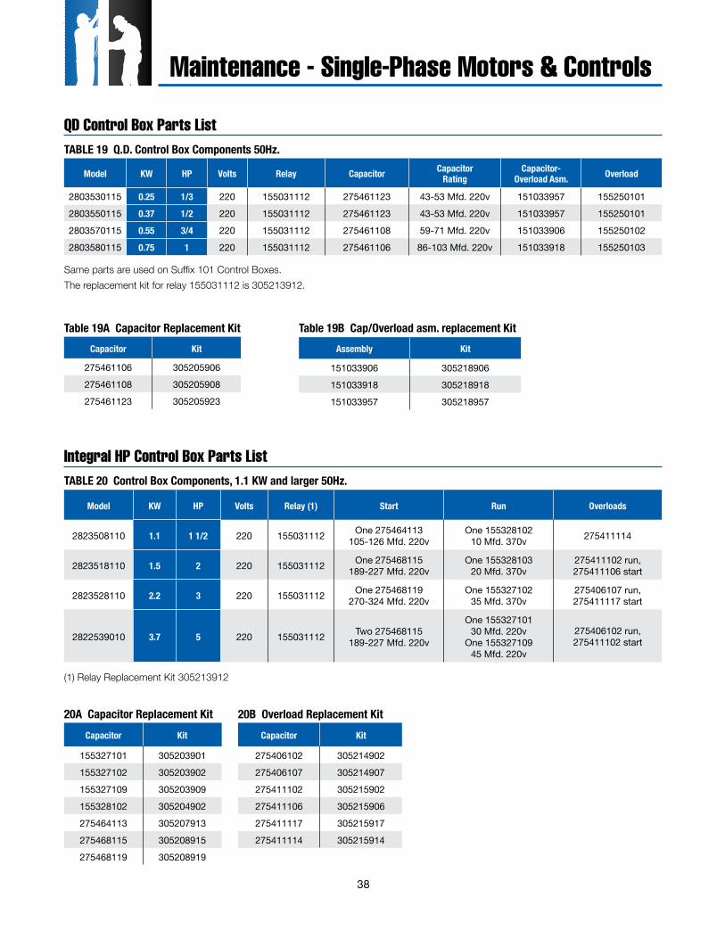
38
Model KW HP Volts Relay Capacitor Capacitor Rating
Capacitor- Overload Asm. Overload
2803530115 0.25 1/3 220 155031112 275461123 43-53 Mfd. 220v 151033957 1552501012803550115 0.37 1/2 220 155031112 275461123 43-53 Mfd. 220v 151033957 1552501012803570115 0.55 3/4 220 155031112 275461108 59-71 Mfd. 220v 151033906 1552501022803580115 0.75 1 220 155031112 275461106 86-103 Mfd. 220v 151033918 155250103
QD Control Box Parts ListTABLE 19 Q.D. Control Box Components 50Hz.
Same parts are used on Suffix 101 Control Boxes.The replacement kit for relay 155031112 is 305213912.
Capacitor Kit
275461106 305205906275461108 305205908275461123 305205923
Table 19A Capacitor Replacement KitAssembly Kit
151033906 305218906151033918 305218918151033957 305218957
Table 19B Cap/Overload asm. replacement Kit
Integral HP Control Box Parts ListTABLE 20 Control Box Components, 1.1 KW and larger 50Hz.
Model KW HP Volts Relay (1) Start Run Overloads
2823508110 1.1 1 1/2 220 155031112 One 275464113 105-126 Mfd. 220v
One 155328102 10 Mfd. 370v 275411114
2823518110 1.5 2 220 155031112 One 275468115 189-227 Mfd. 220v
One 155328103 20 Mfd. 370v
275411102 run, 275411106 start
2823528110 2.2 3 220 155031112 One 275468119 270-324 Mfd. 220v
One 155327102 35 Mfd. 370v
275406107 run, 275411117 start
2822539010 3.7 5 220 155031112 Two 275468115 189-227 Mfd. 220v
One 155327101 30 Mfd. 220v
One 155327109 45 Mfd. 220v
275406102 run, 275411102 start
(1) Relay Replacement Kit 305213912
Capacitor Kit
155327101 305203901155327102 305203902
155327109 305203909155328102 305204902
275464113 305207913275468115 305208915
275468119 305208919
Capacitor Kit
275406102 305214902275406107 305214907
275411102 305215902275411106 305215906
275411117 305215917275411114 305215914
20A Capacitor Replacement Kit 20B Overload Replacement Kit
Maintenance - Single-Phase Motors & Controls
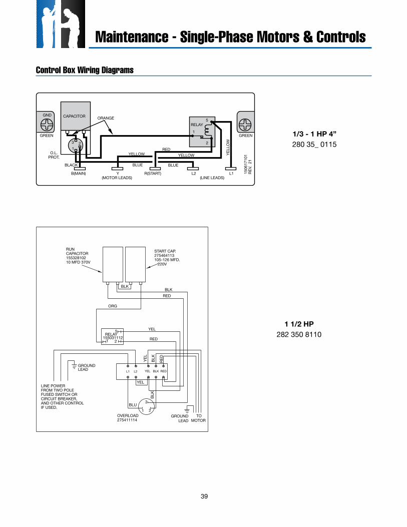
39
YB(MAIN) R(START) L2 L1 1506
1710
1RE
V. 2
1
CAPACITOR
RELAY5
1
21
23
O.L.PROT.
GND
(MOTOR LEADS) (LINE LEADS)
YELL
OW
GREEN
BLUE BLUE
ORANGE
YELLOW YELLOWRED
GREEN
BLACK
Control Box Wiring Diagrams
LINE POWERFROM TWO POLEFUSED SWITCH ORCIRCUIT BREAKER,AND OTHER CONTROLIF USED.
OVERLOAD275411114
TOMOTOR
RED
BLK
YEL
1 2
3BLU
BLK
YEL
RELAY155031112
1 2
5
RED
YEL
START CAP.275464113105-126 MFD. 220V
RUNCAPACITOR15532810210 MFD 370V
BLK
ORG
BLKRED
GROUNDLEAD
GROUNDLEAD
L1 L2 YEL BLK RED
1/3 - 1 HP 4”280 35_ 0115
1 1/2 HP282 350 8110
Maintenance - Single-Phase Motors & Controls
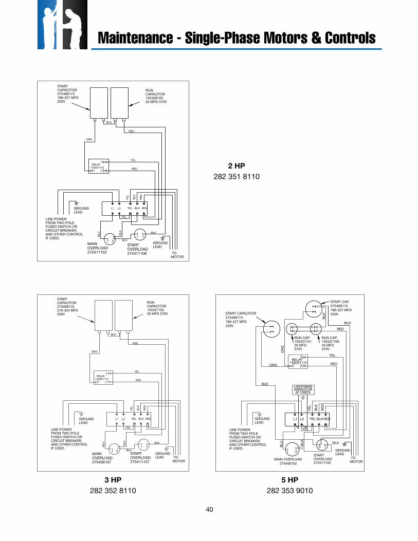
40
STARTOVERLOAD275411106
LINE POWERFROM TWO POLEFUSED SWITCH ORCIRCUIT BREAKER,AND OTHER CONTROLIF USED.
RELAY155031112
1 2
5
TOMOTOR
BLK
RED
RED
YEL
31
MAINOVERLOAD275411102
1 3
RED
BLK
YEL
BLU
BLK
YEL
RUNCAPACITOR15532810320 MFD 370V
STARTCAPACITOR275468115189-227 MFD220V
BLK
BLK
ORG
GROUNDLEAD
GROUNDLEAD
L1 L2 YEL BLK RED
STARTOVERLOAD275411107
LINE POWERFROM TWO POLEFUSED SWITCH ORCIRCUIT BREAKER,AND OTHER CONTROLIF USED.
RELAY155031112
1 2
5
TOMOTOR
BLK
RED
RED
YEL
31
3 HP50 Hz
MAINOVERLOAD275406107
1 3
RED
BLK
YEL
BLU
BLK
YEL
BLK
BLK
ORG
GROUNDLEAD
GROUNDLEAD
RUNCAPACITOR15532710235 MFD 370V
STARTCAPACITOR275468119270-324 MFD330V
L1 L2 YEL BLK RED
STARTOVERLOAD275411102
LINE POWERFROM TWO POLEFUSED SWITCH ORCIRCUIT BREAKER,AND OTHER CONTROLIF USED.
RELAY155031112
START CAPACITOR275468115189-227 MFD220V
1 2
5
TOMOTOR
BLK
RED
RED
ORG
YEL
13
LIGHTNINGARRESTOR(IF USED)
MAIN OVERLOAD275406102
1 2
BLKRE
D
BLK
YEL
BLU
BLK
YEL
BLK
ORG
BLK
RUN CAP15532710945 MFD370V
START CAP.275468115189-227 MFD220V
GROUNDLEAD
GROUNDLEAD
RUN CAP15532710130 MFD370V
L1 L2 YEL BLKRED
2 HP282 351 8110
3 HP282 352 8110
5 HP282 353 9010
Maintenance - Single-Phase Motors & Controls
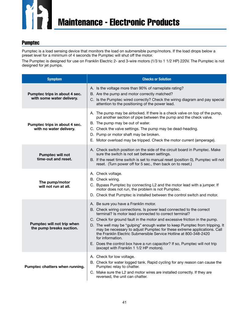
41
Pumptec is a load sensing device that monitors the load on submersible pump/motors. If the load drops below a preset level for a minimum of 4 seconds the Pumptec will shut off the motor.The Pumptec is designed for use on Franklin Electric 2- and 3-wire motors (1/3 to 1 1/2 HP) 220V. The Pumptec is not designed for jet pumps.
Pumptec
Maintenance - Electronic Products
Symptom Checks or Solution
Pumptec trips in about 4 sec. with some water delivery.
A. Is the voltage more than 90% of nameplate rating?B. Are the pump and motor correctly matched?C. Is the Pumptec wired correctly? Check the wiring diagram and pay special
attention to the positioning of the power lead.
Pumptec trips in about 4 sec. with no water delivery.
A. The pump may be airlocked. If there is a check valve on top of the pump, put another section of pipe between the pump and the check valve.
B. The pump may be out of water.C. Check the valve settings. The pump may be dead-heading.D. Pump or motor shaft may be broken.E. Motor overload may be tripped. Check the motor current (amperage).
Pumptec will not time-out and reset.
A. Check switch position on the side of the circuit board in Pumptec. Make sure the switch is not set between settings.
B. If the reset time switch is set to manual reset (position 0), Pumptec will not reset. (Turn power off for 5 sec., then back on to reset.)
The pump/motor will not run at all.
A. Check voltage.B. Check wiring.C. Bypass Pumptec by connecting L2 and the motor lead with a jumper. If
motor does not run, the problem is not Pumptec.D. Check that Pumptec is installed between the control switch and motor.
Pumptec will not trip when the pump breaks suction.
A. Be sure you have a Franklin motor.B. Check wiring connections. Is power lead connected to the correct
terminal? Is motor lead connected to correct terminal?C. Check for ground fault in the motor and excessive friction in the pump.D. The well may be “gulping” enough water to keep Pumptec from tripping. It
may be necessary to adjust Pumptec for these extreme applications. Call the Franklin Electric Submersible Service Hotline at 800-348-2420 for information.
E. Does the control box have a run capacitor? If so, Pumptec will not trip (except with Franklin 1 1/2 HP motors).
Pumptec chatters when running.
A. Check for low voltage.B. Check for water logged tank. Rapid cycling for any reason can cause the
Pumptec relay to chatter.C. Make sure the L2 and motor wires are installed correctly. If they are
reversed, the unit can chatter.
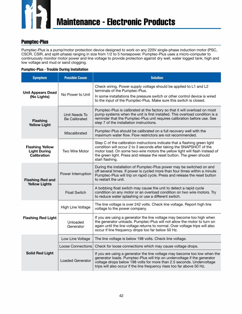
42
Pumptec-Plus is a pump/motor protection device designed to work on any 220V single-phase induction motor (PSC, CSCR, CSIR, and split-phase) ranging in size from 1/2 to 5 horsepower. Pumptec-Plus uses a micro-computer to continuously monitor motor power and line voltage to provide protection against dry well, water logged tank, high and low voltage and mud or sand clogging.
Pumptec-Plus
Symptom Possible Cause Solution
Unit Appears Dead (No Lights) No Power to Unit
Check wiring. Power supply voltage should be applied to L1 and L2 terminals of the Pumptec-Plus. In some installations the pressure switch or other control device is wired to the input of the Pumptec-Plus. Make sure this switch is closed.
Flashing Yellow Light
Unit Needs To Be Calibrated
Pumptec-Plus is calibrated at the factory so that it will overload on most pump systems when the unit is first installed. This overload condition is a reminder that the Pumptec-Plus unit requires calibration before use. See step 7 of the installation instructions.
Miscalibrated Pumptec-Plus should be calibrated on a full recovery well with the maximum water flow. Flow restrictors are not recommended.
Flashing Yellow Light During Calibration
Two Wire Motor
Step C of the calibration instructions indicate that a flashing green light condition will occur 2 to 3 seconds after taking the SNAPSHOT of the motor load. On some two-wire motors the yellow light will flash instead of the green light. Press and release the reset button. The green should start flashing.
Flashing Red and Yellow Lights
Power Interruption
During the installation of Pumptec-Plus power may be switched on and off several times. If power is cycled more than four times within a minute Pumptec-Plus will trip on rapid cycle. Press and release the reset button to restart the unit.
Float SwitchA bobbing float switch may cause the unit to detect a rapid cycle condition on any motor or an overload condition on two wire motors. Try to reduce water splashing or use a different switch.
Flashing Red Light
High Line VoltageThe line voltage is over 242 volts. Check line voltage. Report high line voltage to the power company.
Unloaded Generator
If you are using a generator the line voltage may become too high when the generator unloads. Pumptec-Plus will not allow the motor to turn on again until the line voltage returns to normal. Over voltage trips will also occur if line frequency drops too far below 50 Hz.
Solid Red Light
Low Line Voltage The line voltage is below 198 volts. Check line voltage.
Loose Connections Check for loose connections which may cause voltage drops.
Loaded Generator
If you are using a generator the line voltage may become too low when the generator loads. Pumptec-Plus will trip on undervoltage if the generator voltage drops below 198 volts for more than 2.5 seconds. Undervoltage trips will also occur if the line frequency rises too far above 50 Hz.
Pumptec-Plus - Trouble During Installation
Maintenance - Electronic Products
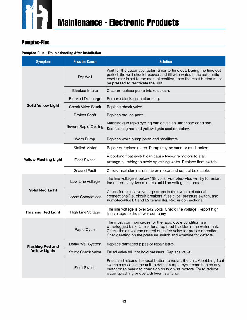
43
Pumptec-Plus
Symptom Possible Cause Solution
Solid Yellow Light
Dry WellWait for the automatic restart timer to time out. During the time out period, the well should recover and fill with water. If the automatic reset timer is set to the manual position, then the reset button must be pressed to reactivate the unit.
Blocked Intake Clear or replace pump intake screen.
Blocked Discharge Remove blockage in plumbing.
Check Valve Stuck Replace check valve.
Broken Shaft Replace broken parts.
Severe Rapid CyclingMachine gun rapid cycling can cause an underload condition. See flashing red and yellow lights section below.
Worn Pump Replace worn pump parts and recalibrate.
Yellow Flashing Light
Stalled Motor Repair or replace motor. Pump may be sand or mud locked.
Float SwitchA bobbing float switch can cause two-wire motors to stall. Arrange plumbing to avoid splashing water. Replace float switch.
Ground Fault Check insulation resistance on motor and control box cable.
Solid Red Light
Low Line VoltageThe line voltage is below 198 volts. Pumptec-Plus will try to restart the motor every two minutes until line voltage is normal.
Loose ConnectionsCheck for excessive voltage drops in the system electrical connections (i.e. circuit breakers, fuse clips, pressure switch, and Pumptec-Plus L1 and L2 terminals). Repair connections.
Flashing Red Light High Line VoltageThe line voltage is over 242 volts. Check line voltage. Report high line voltage to the power company.
Flashing Red and Yellow Lights
Rapid Cycle
The most common cause for the rapid cycle condition is a waterlogged tank. Check for a ruptured bladder in the water tank. Check the air volume control or snifter valve for proper operation. Check setting on the pressure switch and examine for defects.
Leaky Well System Replace damaged pipes or repair leaks.
Stuck Check Valve Failed valve will not hold pressure. Replace valve.
Float Switch
Press and release the reset button to restart the unit. A bobbing float switch may cause the unit to detect a rapid cycle condition on any motor or an overload condition on two wire motors. Try to reduce water splashing or use a different switch.v
Pumptec-Plus - Troubleshooting After Installation
Maintenance - Electronic Products
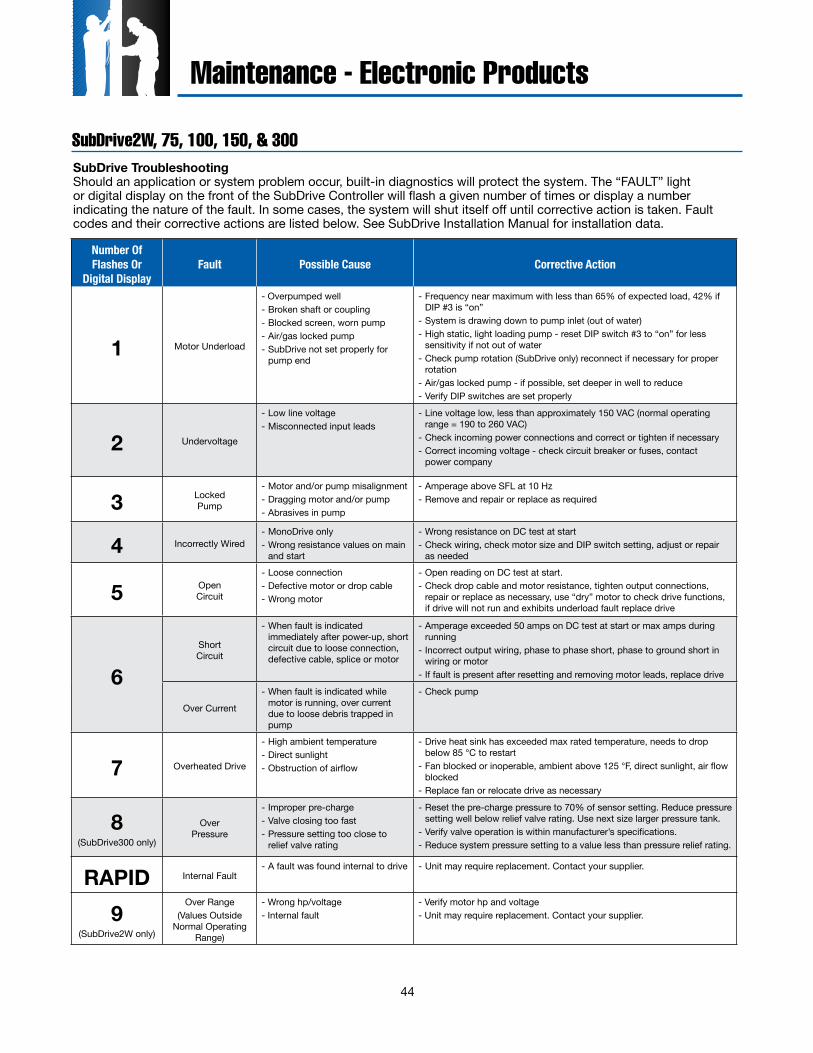
44
SubDrive2W, 75, 100, 150, & 300
Maintenance - Electronic Products
Number Of Flashes Or
Digital DisplayFault Possible Cause Corrective Action
1 Motor Underload
- Overpumped well- Broken shaft or coupling- Blocked screen, worn pump- Air/gas locked pump- SubDrive not set properly for
pump end
- Frequency near maximum with less than 65% of expected load, 42% if DIP #3 is “on”
- System is drawing down to pump inlet (out of water)- High static, light loading pump - reset DIP switch #3 to “on” for less
sensitivity if not out of water- Check pump rotation (SubDrive only) reconnect if necessary for proper
rotation- Air/gas locked pump - if possible, set deeper in well to reduce- Verify DIP switches are set properly
2 Undervoltage
- Low line voltage- Misconnected input leads
- Line voltage low, less than approximately 150 VAC (normal operating range = 190 to 260 VAC)
- Check incoming power connections and correct or tighten if necessary- Correct incoming voltage - check circuit breaker or fuses, contact
power company
3 Locked Pump
- Motor and/or pump misalignment- Dragging motor and/or pump- Abrasives in pump
- Amperage above SFL at 10 Hz- Remove and repair or replace as required
4 Incorrectly Wired- MonoDrive only- Wrong resistance values on main
and start
- Wrong resistance on DC test at start- Check wiring, check motor size and DIP switch setting, adjust or repair
as needed
5 Open Circuit
- Loose connection- Defective motor or drop cable- Wrong motor
- Open reading on DC test at start.- Check drop cable and motor resistance, tighten output connections,
repair or replace as necessary, use “dry” motor to check drive functions, if drive will not run and exhibits underload fault replace drive
6Short Circuit
- When fault is indicated immediately after power-up, short circuit due to loose connection, defective cable, splice or motor
- Amperage exceeded 50 amps on DC test at start or max amps during running
- Incorrect output wiring, phase to phase short, phase to ground short in wiring or motor
- If fault is present after resetting and removing motor leads, replace drive
Over Current
- When fault is indicated while motor is running, over current due to loose debris trapped in pump
- Check pump
7 Overheated Drive
- High ambient temperature- Direct sunlight- Obstruction of airflow
- Drive heat sink has exceeded max rated temperature, needs to drop below 85 °C to restart
- Fan blocked or inoperable, ambient above 125 °F, direct sunlight, air flow blocked
- Replace fan or relocate drive as necessary
8(SubDrive300 only)
Over Pressure
- Improper pre-charge- Valve closing too fast- Pressure setting too close to
relief valve rating
- Reset the pre-charge pressure to 70% of sensor setting. Reduce pressure setting well below relief valve rating. Use next size larger pressure tank.
- Verify valve operation is within manufacturer’s specifications.- Reduce system pressure setting to a value less than pressure relief rating.
RAPID Internal Fault- A fault was found internal to drive - Unit may require replacement. Contact your supplier.
9(SubDrive2W only)
Over Range(Values Outside
Normal Operating Range)
- Wrong hp/voltage- Internal fault
- Verify motor hp and voltage- Unit may require replacement. Contact your supplier.
SubDrive TroubleshootingShould an application or system problem occur, built-in diagnostics will protect the system. The “FAULT” light or digital display on the front of the SubDrive Controller will flash a given number of times or display a number indicating the nature of the fault. In some cases, the system will shut itself off until corrective action is taken. Fault codes and their corrective actions are listed below. See SubDrive Installation Manual for installation data.
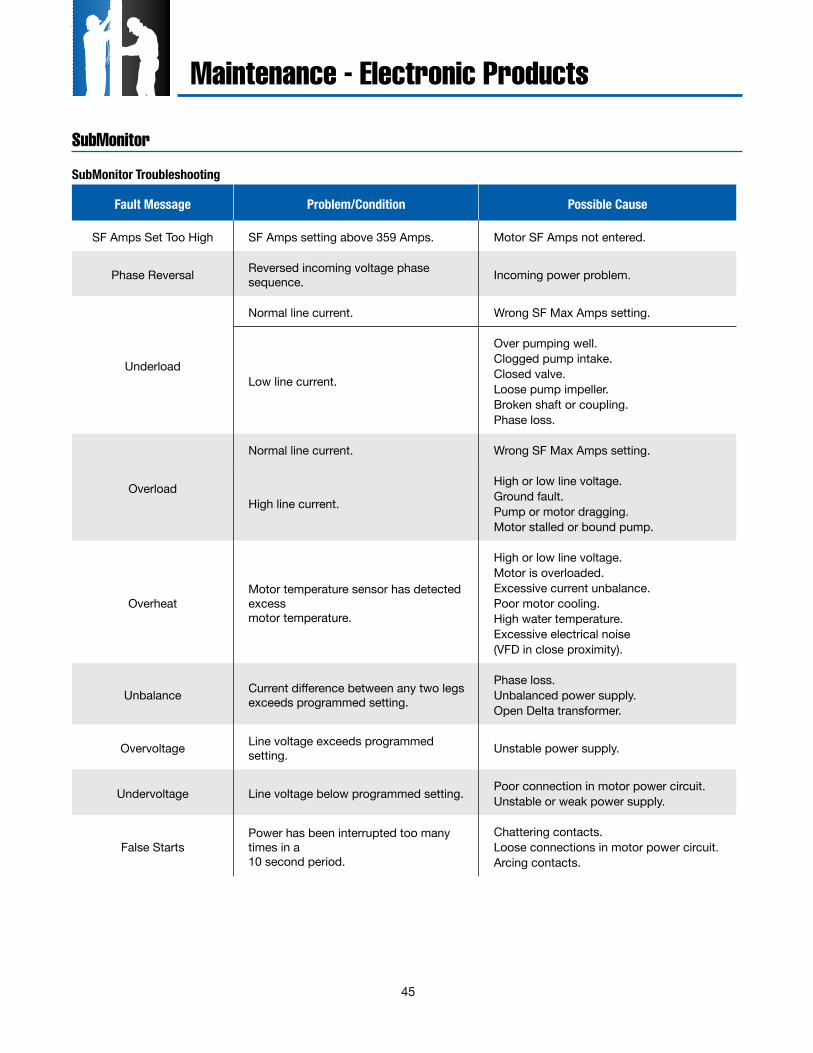
45
Maintenance - Electronic Products
SubMonitor Troubleshooting
Fault Message Problem/Condition Possible Cause
SF Amps Set Too High SF Amps setting above 359 Amps. Motor SF Amps not entered.
Phase Reversal Reversed incoming voltage phase sequence. Incoming power problem.
Underload
Normal line current. Wrong SF Max Amps setting.
Low line current.
Over pumping well.Clogged pump intake.Closed valve.Loose pump impeller.Broken shaft or coupling.Phase loss.
Overload
Normal line current. Wrong SF Max Amps setting.
High line current.
High or low line voltage.Ground fault.Pump or motor dragging.Motor stalled or bound pump.
OverheatMotor temperature sensor has detected excess motor temperature.
High or low line voltage.Motor is overloaded.Excessive current unbalance.Poor motor cooling.High water temperature.Excessive electrical noise(VFD in close proximity).
Unbalance Current difference between any two legs exceeds programmed setting.
Phase loss.Unbalanced power supply.Open Delta transformer.
Overvoltage Line voltage exceeds programmed setting. Unstable power supply.
Undervoltage Line voltage below programmed setting. Poor connection in motor power circuit.Unstable or weak power supply.
False StartsPower has been interrupted too many times in a 10 second period.
Chattering contacts.Loose connections in motor power circuit.Arcing contacts.
SubMonitor
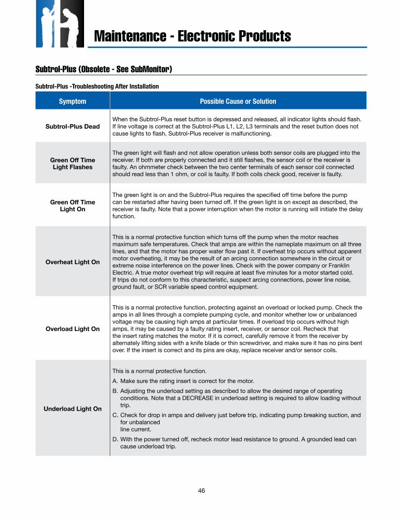
46
Maintenance - Electronic Products
Subtrol-Plus (Obsolete - See SubMonitor)
Subtrol-Plus -Troubleshooting After Installation
Symptom Possible Cause or Solution
Subtrol-Plus DeadWhen the Subtrol-Plus reset button is depressed and released, all indicator lights should flash. If line voltage is correct at the Subtrol-Plus L1, L2, L3 terminals and the reset button does not cause lights to flash, Subtrol-Plus receiver is malfunctioning.
Green Off Time Light Flashes
The green light will flash and not allow operation unless both sensor coils are plugged into the receiver. If both are properly connected and it still flashes, the sensor coil or the receiver is faulty. An ohmmeter check between the two center terminals of each sensor coil connected should read less than 1 ohm, or coil is faulty. If both coils check good, receiver is faulty.
Green Off TimeLight On
The green light is on and the Subtrol-Plus requires the specified off time before the pump can be restarted after having been turned off. If the green light is on except as described, the receiver is faulty. Note that a power interruption when the motor is running will initiate the delay function.
Overheat Light On
This is a normal protective function which turns off the pump when the motor reaches maximum safe temperatures. Check that amps are within the nameplate maximum on all three lines, and that the motor has proper water flow past it. If overheat trip occurs without apparent motor overheating, it may be the result of an arcing connection somewhere in the circuit or extreme noise interference on the power lines. Check with the power company or Franklin Electric. A true motor overheat trip will require at least five minutes for a motor started cold. If trips do not conform to this characteristic, suspect arcing connections, power line noise, ground fault, or SCR variable speed control equipment.
Overload Light On
This is a normal protective function, protecting against an overload or locked pump. Check the amps in all lines through a complete pumping cycle, and monitor whether low or unbalanced voltage may be causing high amps at particular times. If overload trip occurs without high amps, it may be caused by a faulty rating insert, receiver, or sensor coil. Recheck that the insert rating matches the motor. If it is correct, carefully remove it from the receiver by alternately lifting sides with a knife blade or thin screwdriver, and make sure it has no pins bent over. If the insert is correct and its pins are okay, replace receiver and/or sensor coils.
Underload Light On
This is a normal protective function.A. Make sure the rating insert is correct for the motor.B. Adjusting the underload setting as described to allow the desired range of operating
conditions. Note that a DECREASE in underload setting is required to allow loading without trip.
C. Check for drop in amps and delivery just before trip, indicating pump breaking suction, and for unbalanced line current.
D. With the power turned off, recheck motor lead resistance to ground. A grounded lead can cause underload trip.
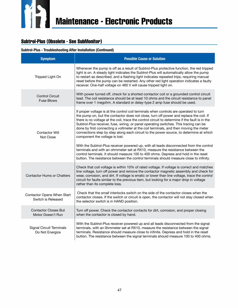
47
Maintenance - Electronic Products
Subtrol-Plus (Obsolete - See SubMonitor)Subtrol-Plus - Troubleshooting After Installation (Continued)
Symptom Possible Cause or Solution
Tripped Light On
Whenever the pump is off as a result of Subtrol-Plus protective function, the red tripped light is on. A steady light indicates the Subtrol-Plus will automatically allow the pump to restart as described, and a flashing light indicates repeated trips, requiring manual reset before the pump can be restarted. Any other red light operation indicates a faulty receiver. One-half voltage on 460 V will cause tripped light on.
Control Circuit Fuse Blows
With power turned off, check for a shorted contactor coil or a grounded control circuit lead. The coil resistance should be at least 10 ohms and the circuit resistance to panel frame over 1 megohm. A standard or delay-type 2 amp fuse should be used.
Contactor Will Not Close
If proper voltage is at the control coil terminals when controls are operated to turn the pump on, but the contactor does not close, turn off power and replace the coil. If there is no voltage at the coil, trace the control circuit to determine if the fault is in the Subtrol-Plus receiver, fuse, wiring, or panel operating switches. This tracing can be done by first connecting a voltmeter at the coil terminals, and then moving the meter connections step by step along each circuit to the power source, to determine at which component the voltage is lost.
With the Subtrol-Plus receiver powered up, with all leads disconnected from the control terminals and with an ohmmeter set at RX10, measure the resistance between the control terminals. It should measure 100 to 400 ohms. Depress and hold in the reset button. The resistance between the control terminals should measure close to infinity.
Contactor Hums or Chatters
Check that coil voltage is within 10% of rated voltage. If voltage is correct and matches line voltage, turn off power and remove the contactor magnetic assembly and check for wear, corrosion, and dirt. If voltage is erratic or lower than line voltage, trace the control circuit for faults similar to the previous item, but looking for a major drop in voltage rather than its complete loss.
Contactor Opens When StartSwitch is Released
Check that the small interlocks switch on the side of the contactor closes when the contactor closes. If the switch or circuit is open, the contactor will not stay closed when the selector switch is in HAND position.
Contactor Closes ButMotor Doesn’t Run
Turn off power. Check the contactor contacts for dirt, corrosion, and proper closing when the contactor is closed by hand.
Signal Circuit TerminalsDo Not Energize
With the Subtrol-Plus receiver powered up and all leads disconnected from the signal terminals, with an 0hmmeter set at RX10, measure the resistance between the signal terminals. Resistance should measure close to infinite. Depress and hold in the reset button. The resistance between the signal terminals should measure 100 to 400 ohms.
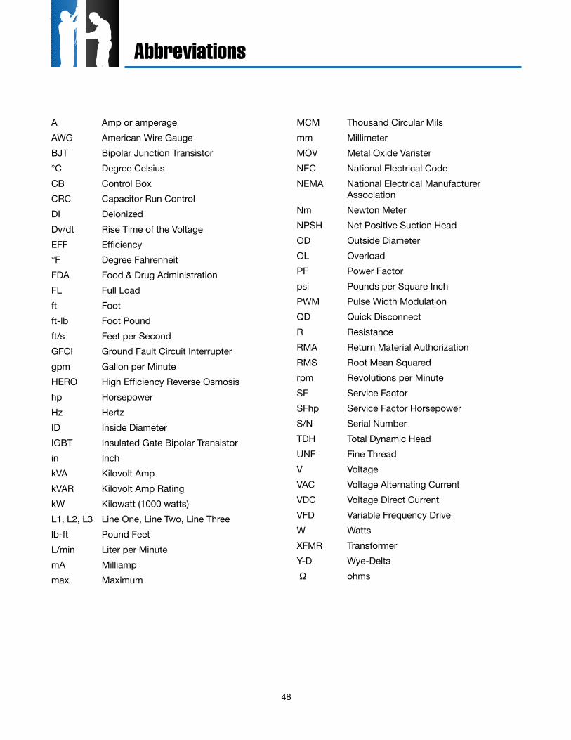
48
A Amp or amperageAWG American Wire GaugeBJT Bipolar Junction Transistor°C Degree CelsiusCB Control BoxCRC Capacitor Run ControlDI DeionizedDv/dt Rise Time of the VoltageEFF Efficiency°F Degree FahrenheitFDA Food & Drug AdministrationFL Full Loadft Footft-lb Foot Poundft/s Feet per SecondGFCI Ground Fault Circuit Interruptergpm Gallon per MinuteHERO High Efficiency Reverse Osmosishp HorsepowerHz HertzID Inside DiameterIGBT Insulated Gate Bipolar Transistorin InchkVA Kilovolt AmpkVAR Kilovolt Amp RatingkW Kilowatt (1000 watts)L1, L2, L3 Line One, Line Two, Line Threelb-ft Pound FeetL/min Liter per MinutemA Milliampmax Maximum
MCM Thousand Circular Milsmm MillimeterMOV Metal Oxide VaristerNEC National Electrical CodeNEMA National Electrical Manufacturer
AssociationNm Newton MeterNPSH Net Positive Suction HeadOD Outside DiameterOL OverloadPF Power Factorpsi Pounds per Square InchPWM Pulse Width ModulationQD Quick DisconnectR ResistanceRMA Return Material AuthorizationRMS Root Mean Squaredrpm Revolutions per MinuteSF Service FactorSFhp Service Factor HorsepowerS/N Serial NumberTDH Total Dynamic HeadUNF Fine ThreadV VoltageVAC Voltage Alternating CurrentVDC Voltage Direct CurrentVFD Variable Frequency DriveW WattsXFMR TransformerY-D Wye-Delta Ω ohms
Abbreviations

49

50
notes

Phone Franklin’s toll free SERVICE HOTLINE for answers to your pump andmotor installation questions. When you call, a Franklin expert will offer assistance
in troubleshooting and provide immediate answers to your system application questions. Technical support is also available online. Visit our website at:
TOLL FREE HELP FROM A FRIEND800-348-2420 • 260-827-5102 (fax)
www.franklinwater.com
The Company You Trust Deep Down
Find knowledgeable, real-world business insights for ground water professionals at:
www.franklininthefield.com
M1339 08.13