Embed Size (px)
Citation preview
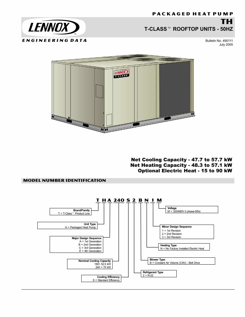
thT−CLASS� ROOFTOP UNITS − 50HZ
P A C K A G E D h e a t p u m p
E N G I N E E R I N G D A T A Bulletin No. 490111
July 2005
Net Cooling Capacity − 47.7 to 57.7 kWNet Heating Capacity − 48.3 to 57.1 kW
Optional Electric Heat − 15 to 90 kW
MODEL NUMBER IDENTIFICATION
T H A M1240 S N2 B
Major Design SequenceA = 1st Generation
B = 2nd GenerationC = 3rd GenerationE = 4th Generation
Brand/FamilyT = T−Class� Product Line
Unit TypeH = Packaged Heat Pump
Nominal Cooling Capacity180= 52.5 kW240 = 70 kW
Cooling EfficiencyS = Standard Efficiency
Minor Design Sequence
1 = 1st Revision2 = 2nd Revision3 = 3rd Revision
VoltageM = 320/480V-3 phase-50hz
Refrigerant Type2 = R−22
Blower TypeB = Constant Air Volume (CAV) − Belt Drive
Heating TypeN = No Factory Installed Electric Heat
50hz − T−Class Packaged Heat Pump 15 and 20 tons / Page 2
TABLE OF CONTENTS
Blower Data Pages 10−13. . . . . . . . . . . . . . . . . . . . . . . . . . . . . . . . . . . . . . . . . . . . . . . . . . . . . . . . . . . . .
Cooling and Heating Ratings Pages 2−9. . . . . . . . . . . . . . . . . . . . . . . . . . . . . . . . . . . . . . . . . . . . . . . . .
Dimensions Pages 17−22. . . . . . . . . . . . . . . . . . . . . . . . . . . . . . . . . . . . . . . . . . . . . . . . . . . . . . . . . . . . . .
Electric Heat Capacities Page 14. . . . . . . . . . . . . . . . . . . . . . . . . . . . . . . . . . . . . . . . . . . . . . . . . . . . . . .
Electrical / Electric Heat Data Page 14. . . . . . . . . . . . . . . . . . . . . . . . . . . . . . . . . . . . . . . . . . . . . . . . . .
Features and Benefits Pages 2−4. . . . . . . . . . . . . . . . . . . . . . . . . . . . . . . . . . . . . . . . . . . . . . . . . . . . . . .
Installation Clearances Page 13. . . . . . . . . . . . . . . . . . . . . . . . . . . . . . . . . . . . . . . . . . . . . . . . . . . . . . . .
Model Number Identification Page 1. . . . . . . . . . . . . . . . . . . . . . . . . . . . . . . . . . . . . . . . . . . . . . . . . . . .
Options / Accessories Pages 4−6. . . . . . . . . . . . . . . . . . . . . . . . . . . . . . . . . . . . . . . . . . . . . . . . . . . . . . .
Specifications Page 7. . . . . . . . . . . . . . . . . . . . . . . . . . . . . . . . . . . . . . . . . . . . . . . . . . . . . . . . . . . . . . . . .
Sound Data Page 13. . . . . . . . . . . . . . . . . . . . . . . . . . . . . . . . . . . . . . . . . . . . . . . . . . . . . . . . . . . . . . . . .
Temperature Control Systems Page 15. . . . . . . . . . . . . . . . . . . . . . . . . . . . . . . . . . . . . . . . . . . . . . . . . .
Weight Data Page 16. . . . . . . . . . . . . . . . . . . . . . . . . . . . . . . . . . . . . . . . . . . . . . . . . . . . . . . . . . . . . . . . .
FEATURES AND BENEFITS
PERFORMANCE/QUALITYComponents bonded for grounding tomeet safety standards for servicingrequired by Underwriters Laboratories(UL) and the InternationalElectrotechnical Commission (IEC).Cooling performance is rated at testconditions included in Air−Conditioningand Refrigeration Institute (ARI)Standard 340/360−2000 while operatingat rated voltage and air volumes.International Organization forStandardization (ISO) 9001 RegisteredManufacturing Quality System
COOLING/HEATING SYSTEMDesigned to maximize sensible andlatent cooling performance at designconditions.System can operate from −1°C to 52°Cwithout any additional controls.
CompressorsResiliently mounted on rubbergrommets for quiet operation.Copeland Scroll� compressors forhigh performance, reliability and quietoperation.
Compressor Crankcase HeatersProtects against refrigerant migrationthat can occur during low ambientoperation.
Check/Thermal Expansion ValvesAssures optimal performancethroughout the application range.Removable element head.
Filter/DriersHigh capacity filter/driers protect thesystem from dirt and moisture.
FreezestatsProtects the indoor coil from damagingice build−up due to conditions such aslow/no air flow, or low/no refrigerantcharge.
High Pressure SwitchesProtects the compressor from overloadconditions such as dirty condensercoils, blocked refrigerant flow, or loss ofoutdoor fan operation.
Low Pressure SwitchesProtects the compressor from lowpressure conditions such as lowrefrigerant charge, or low/no air flow.
Defrost ControlProvides a defrost cycle, if needed,every 30 or 60 or 90 minutes(adjustable) of compressor �on" time atoutdoor coil temperature below 2�C.Pressure switch mounted on outdoorcoil vapor line terminates defrost cycle.
Reversing Valves4-way interchange reversing valveeffects a rapid change in direction ofrefrigerant flow resulting in quickchangeover from cooling to heating andvice versa.
Coil ConstructionCopper tube construction, enhancedrippled−edge aluminum fins, flaredshoulder tubing connections, silversoldered construction for improved heattransfer. Factory leak tested.
Indoor CoilCross row circuiting with rifled coppertubing optimizes both sensible andlatent cooling capacity. Low fin per inchcount minimizes air pressure drop.
Outdoor CoilTwo independent formed coils allowsseparation for cleaning.
Condensate Drain PanPainted, galvanized pan with positiveslope.Drain connection extends outside unit.
Outdoor Coil Fan MotorsThermal overload protected, totallyenclosed, permanently lubricated ballbearings, shaft up, independent motormount.
Outdoor Coil FanPVC coated fan guard furnished.
REQUIRED SELECTIONSCapacitySpecify the nominal capacity of the unit.
ACCESSORIES − Field InstalledCondensate Drain Trap − Available incopper or PVC.Low Ambient Kit − Cycles the outdoorfan while allowing compressoroperation in the cooling cycle. Thisintermittent fan operation allows thesystem to operate without icing theevaporator coil and losing capacity.Designed for use in ambienttemperatures no lower than −17.8°C.
ELECTRICAL
ACCESSORIES − Field Installed
Electric HeatHelix wound nichrome elements, timedelay for element staging, individualelement limit controls, wiring harness,may be two-stage controlled. Thefollowing must be ordered extra whenfield installed electric heat is used: UnitFuse Block and Electric Heat ControlModule. See Electrical / Electric Heattables for ordering information.
BLOWERSupply air fan provides a wide range ofair flow capability. Stocked models (unitstypically in−stock at warehouses) areequipped with standard staticmotor/drive combinations. Special orderhigh and low static motor and driveoptions are available CTO (configure toorder) offering an even wider range ofcapability.
Supply Air MotorOverload protected with permanentlylubricated ball bearings ensures durableoperation. Special order high and lowstatic motors provide a higher level of airperformance for demandingapplications.
Supply Air BlowerA double inlet wheel with forward curveblades provide maximum airperformance and quiet operation.Dynamically balanced with permanentlylubricated ball bearings assure long,reliable operation. Adjustable pulleysallow air to be precisely tuned to theneeds of the application.
REQUIRED SELECTIONS
Supply Air BlowerSpecify Blower drive kit (See BlowerData Tables for specifications).
B
C
D
E
F
G
H

50hz − T−Class Packaged Heat Pump 15 and 20 tons / Page 3
FEATURES AND BENEFITS
B
C
D
E
F
G
H
J
I
K
L
M
AIR FILTERSDisposable 51 mm pleated MERV 7filters (Minimum Efficiency ReportingValue based on American Society ofRefrigeration and Air−ConditioningEngineers (ASHRAE) 52.2) meet therequirements for ASHRAE 62 forimproved indoor air quality.
ACCESSORIES − Field InstalledMERV 11 Filters − Disposable 51 mmpleated MERV 11 filters (MinimumEfficiency Reporting Value based onAmerican Society of Refrigeration andAir Conditioning Engineers (ASHRAE)52.2) are available for improved indoorair quality .
Replaceable MediaPermanent, metal frame filters with 51mm polyester, replaceable media.
CONTROLS
Unit ControllerSolid−state microprocessor−basedcontrol board that provides flexiblecontrol of cooling functions. All controlvoltage is provided via a 24V(secondary) transformer with built−incircuit breaker protection. Built−infunctions include:Blower On/Off Delay − Time delaybetween blower on and off cyclesprovides a more even supply airtemperature during heating.Built−in Control Parameters − Savesinstallation time as no programming isrequired.Minimum Compressor Run Time −Ensures proper oil return to thecompressor.Night Setback Mode − Saves energyby closing outdoor air dampers andoperating supply fan on thermostatdemand only.Heat/Cool Staging − Capable of up to 2heat / 2 cool staging with a third partyDDC control system or compatiblethermostat.Thermostat Bounce Delay − Protectscompressor from short cycling when amechanical thermostat is used.
ACCESSORIES − Field Installed
Blower Proving SwitchUses a static pressure sensor tomonitors blower operation and shutsdown unit if blower fails.
Temperature Control SystemsSee Page 15
Dirty Filter SwitchSenses static pressure increaseindicating dirty filter condition.
Smoke DetectorPhotoelectric type, installed in supply airsection or return air section or bothsections
Indoor Air Quality (CO2) SensorMonitors CO2 levels.
CABINET
ConstructionHeavy−gauge steel panels and fullperimeter heavy−gauge galvanizedsteel base rail provides structuralintegrity for transportation, handling,and installation.Base rails have rigging holes. Threesides of the base rail have fork slots.Raised edges around duct and powerentry openings in the bottom of the unitprovide additional protection againstwater entering the building.
Air−Flow ChoiceUnits are available in down−flow(vertical) or horizontal return air flowconfiguration.Horizontal air flow requires HorizontalRoof Curb.Horizontal Return Air Panel Kit is alsorequired if converting a down−flowconfigured unit to horizontal air flow.
Power EntryElectrical lines can be brought throughthe unit base or through horizontalaccess knock−outs.
Exterior PanelsConstructed of heavy−gauge,galvanized steel with a two−layerenamel paint finish.
InsulationAll panels adjacent to conditioned air arefully insulated with non−hygroscopicfiberglass insulation.Unit base is fully insulated. Theinsulation also serves as an air seal tothe roof curb, eliminating the need toadd a seal during installation.
Access PanelsAccess panels are provided for thecompressor/controls/heating sectionand the blower access and airfilter/economizer section.
REQUIRED SELECTIONS
Air Flow ConfigurationSpecify horizontal or down−flow(vertical).
OPTIONS − Factory Installed
Corrosion ProtectionA completely flexible immersed coatingwith an electrodeposited dry filmprocess. (AST ElectroFin E−Coat)Meets Mil Spec MIL−P−53084, ASTMB117 Standard Method Salt SprayTesting, ASTM 1153 StandardSpecification for Methyl Isobutyl Ketone.
ACCESSORIES − Field Installed
Coil GuardsPainted, galvanized steel wire guards toprotect outdoor coil. Not used with HailGuards.
Hail GuardsConstructed of heavy gauge steel,painted to match cabinet, helps protectoutdoor coils from hail damage. Notused with Coil Guards.
Horizontal Return Air Panel KitRequired for horizontal applications withHorizontal Roof Curb, contains panelwith return air opening for fieldreplacement of existing unit panel andpanel to cover bottom return air openingin unit, see dimension drawings.
I
J
K
L
50hz − T−Class Packaged Heat Pump 15 and 20 tons / Page 4
FEATURES AND BENEFITS
SERVICEABILITYDesigned to streamline generalmaintenance and decreasetroubleshooting time.
Marked & Color−Coded WiringAll electrical wiring is color−coded andmarked to identify which components itis connecting.
Electrical PlugsPositive connection electrical plugs areused to connect common accessoriesor maintenance parts for easy removalor installation.
Access PanelsLarge access panels are provided forquick and easy access to maintenanceareas.
Blower AccessBlower assembly slides out of the unitfor easy access.
TXV AccessThermal expansion valves are locatednear the perimeter of the unit for easieraccess.
Check/Thermal Expansion ValvesRemovable element head allowschange out of element and bulb withoutremoving the TXV.
Coil CleaningIndependently formed condenser coilsallow separation for easier cleaning.
Standard ComponentsA large number of commonmaintenance parts are standardthroughout the entire range of sizes,reducing the need to carry a lot ofdifferent parts to the job or in inventory.
Compressor AccessCompressors are located near theperimeter of the unit for easier access.
Compressor CompartmentCompressors are isolated from thecondenser air flow allowing systemoperation checks to be done withoutchanging the air flow across the outdoorcoils.
OPTIONS/ACCESSORIES
ECONOMIZER/OUTDOORAIR/EXHAUST ACCESSORIES
Factory or Field Installed
EconomizerParallel, gear−driven action return airand outdoor air dampers, plug-inconnections to unit, nylon bearings,neoprene seals, 24 volt, spring returnmotor, adjustable minimum damperposition, damper assembly slides inunit, outdoor air hood must be orderedseparately, choice of economizercontrols. Economizer modulatesdampers to maintain a 13°C dischargeair temperature.
Economizer Enthalpy ControlSenses outdoor air enthalpy andenables economizer if the enthalpy isless than the setpoint of the control.
Down−Flow Barometric ReliefDampersAllows relief of excess return air staticwhen economizer is near full open.Aluminum blade dampers prevent blowback and outdoor air infiltration duringoff cycle. Bird screen furnished.
Outdoor Air Damper Section25% Manual Outdoor Air Dampers −Parallel blade dampers are manuallyadjustable to a fixed position.25% Automatic Outdoor Air Damper −Parallel blade, gear−driven dampers areautomatically adjusted with atwo−position damper motor.
Economizer and Outdoor Air DamperApplication Note − Minimum mixed airtemperature in heating mode −1°CMaximum mixed air temperature incooling mode: 32°C
Power Exhaust FansC1PWRE20C−1 models have two, 249W (1/3 hp) motors with 508 mm (20 in.),five blade propeller−type fans with a totalpower input of 575 Watts and a total airvolume of 3395 L/s (7190 cfm) at 0 Pa (0in. w.g.).Motor is inherently protected andenclosed for maximum protection fromweather, dust and corrosion. Installsinternal to unit for down-flowapplications only with economizeroption, provides exhaust air pressurerelief, interlocked to run when return airdampers are closed and supply airblower is operating, fan runs whenoutdoor air dampers are 50% open(adjustable), motor is overloadprotected, steel cabinet and hoodpainted to match unit, requires optionalDown-flow Economizer BarometricRelief Dampers. See Power Exhaust Blower Tables.
Field InstalledEconomizer Control
Sensible Control − Senses outdoor airtemperature and enables theeconomizer if the temperature is lessthan the set point of the control.Differential Sensible Control − Twotemperature sensors allow the controlto select between outdoor air or returnair, whichever has lower temperature.Enthalpy Control − Senses outdoor airenthalpy and enables economizer if theenthalpy is less than the setpoint of thecontrol.Differential Enthalpy Control − Twosolid-state enthalpy sensors allow thecontrol to select between outdoor air orreturn air, whichever has lowerenthalpy.
Outdoor Air HoodRequired with Economizer, Outdoor AirDamper Sections, cleanable aluminummesh fresh air filters furnished.
Down−Flow Barometric ReliefDamper HoodProtects exhaust air from recirculatinginto outdoor air stream.
Horizontal Barometric ReliefDampersAllows relief of excess air wheneconomizer is near full open. Aluminumblade dampers prevent blow back andoutdoor air infiltration during off cycle.Field installed in return air duct. Birdscreen furnished.
CEILING DIFFUSERS
ACCESSORIES − Field InstalledCeiling DiffusersAluminum grilles, large center grille,insulated diffuser box with flanges,hanging rings furnished, interiortransition (even air flow), internallysealed (prevents recirculation), adaptsto T-bar ceiling grids or plaster ceilings.
Transitions (Supply and Return)Used with diffusers, installs in roof curb,galvanized steel construction, flangesfurnished for duct connection todiffusers, fully insulated.
ROOF CURBS
ACCESSORIES − Field InstalledNailer strip furnished, mates to unit,shipped knocked down.
Standard Down−FlowUS National Roofing ContractorsApproved, available in 356 mm and 610mm heights
HorizontalConverts unit from down-flow tohorizontal (side) air flow, return air is onunit, supply air is on curb, see dimensiondrawings. Curbs for rooftop applicationsmeet National Roofing Coderequirements. Requires HorizontalReturn Air Panel. Available in 660 mm,762 mm, 940 mm and 1041 mm heights.Optional Insulation Kit is available tohelp prevent sweating.
Cliplock 1000 Full PerimeterDown−FlowAvailable in 356 mm, 457 mm, and 610mm heights.
M
50hz − T−Class Packaged Heat Pump 15 and 20 tons / Page 5
OPTIONs / ACCESSORIES
Item 180 240
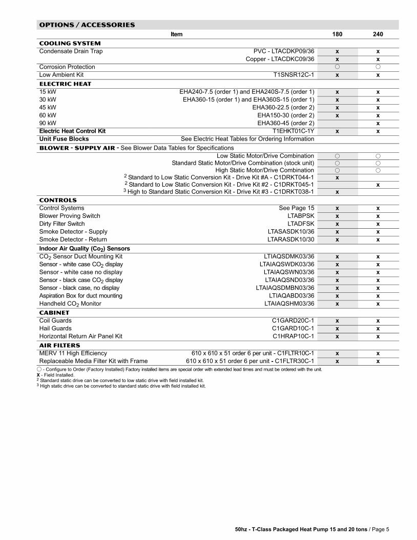
COOLING SYSTEM
Condensate Drain Trap PVC − LTACDKP09/36 x xp
Copper − LTACDKC09/36 x x
Corrosion Protection � �
Low Ambient Kit T1SNSR12C−1 x x
ELECTRIC HEAT
15 kW EHA240−7.5 (order 1) and EHA240S−7.5 (order 1) x x
30 kW EHA360−15 (order 1) and EHA360S−15 (order 1) x x
45 kW EHA360−22.5 (order 2) x x
60 kW EHA150−30 (order 2) x x
90 kW EHA360−45 (order 2) x
Electric Heat Control Kit T1EHKT01C−1Y x x
Unit Fuse Blocks See Electric Heat Tables for Ordering Information
Blower − SUPPLY AIR − See Blower Data Tables for Specifications
Low Static Motor/Drive Combination � �
Standard Static Motor/Drive Combination (stock unit) � �
High Static Motor/Drive Combination � �2 Standard to Low Static Conversion Kit − Drive Kit #A − C1DRKT044−1 x2 Standard to Low Static Conversion Kit − Drive Kit #2 − C1DRKT045−1 x3 High to Standard Static Conversion Kit − Drive Kit #3 − C1DRKT038−1 x
CONTROLS
Control Systems See Page 15 x x
Blower Proving Switch LTABPSK x x
Dirty Filter Switch LTADFSK x x
Smoke Detector − Supply LTASASDK10/36 x x
Smoke Detector − Return LTARASDK10/30 x x
Indoor Air Quality (Co2) Sensors
CO2 Sensor Duct Mounting Kit LTIAQSDMK03/36 x x
Sensor − white case CO2 display LTAIAQSWDK03/36 x x
Sensor − white case no display LTAIAQSWN03/36 x x
Sensor − black case CO2 display LTAIAQSND03/36 x x
Sensor − black case, no display LTAIAQSDMBN03/36 x x
Aspiration Box for duct mounting LTIAQABD03/36 x x
Handheld CO2 Monitor LTAIAQSHM03/36 x x
CABINET
Coil Guards C1GARD20C−1 x x
Hail Guards C1GARD10C−1 x x
Horizontal Return Air Panel Kit C1HRAP10C−1 x x
AIR FILTERS
MERV 11 High Efficiency 610 x 610 x 51 order 6 per unit − C1FLTR10C−1 x x
Replaceable Media Filter Kit with Frame 610 x 610 x 51 order 6 per unit − C1FLTR30C−1 x x
� − Configure to Order (Factory Installed) Factory installed items are special order with extended lead times and must be ordered with the unit.
X − Field Installed.2 Standard static drive can be converted to low static drive with field installed kit.3 High static drive can be converted to standard static drive with field installed kit.
50hz − T−Class Packaged Heat Pump 15 and 20 tons / Page 6
OPTIONs / ACCESSORIES
Item 180 240
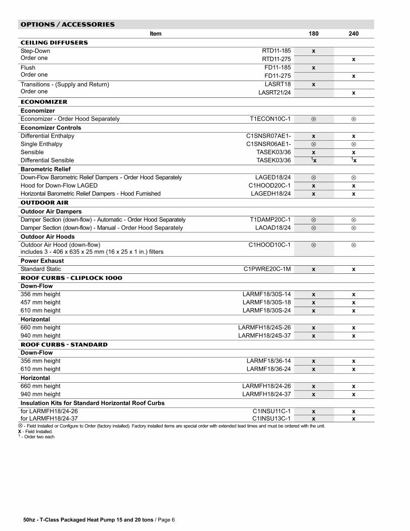
CEILING DIFFUSERS
Step−DownO
RTD11−185 xpOrder one RTD11−275 x
FlushO
FD11−185 x
Order one FD11−275 x
Transitions − (Supply and Return)O
LASRT18 x( pp y )Order one LASRT21/24 x
ECONOMIZER
Economizer
Economizer − Order Hood Separately T1ECON10C−1 � �
Economizer Controls
Differential Enthalpy C1SNSR07AE1− x x
Single Enthalpy C1SNSR06AE1− � �
Sensible TASEK03/36 x x
Differential Sensible TASEK03/36 1x 1x
Barometric Relief
Down−Flow Barometric Relief Dampers − Order Hood Separately LAGED18/24 � �
Hood for Down−Flow LAGED C1HOOD20C−1 x x
Horizontal Barometric Relief Dampers − Hood Furnished LAGEDH18/24 x x
OUTDOOR AIR
Outdoor Air Dampers
Damper Section (down−flow) − Automatic − Order Hood Separately T1DAMP20C−1 � �
Damper Section (down−flow) − Manual − Order Hood Separately LAOAD18/24 � �
Outdoor Air Hoods
Outdoor Air Hood (down−flow)includes 3 − 406 x 635 x 25 mm (16 x 25 x 1 in.) filters
C1HOOD10C−1 � �
Power Exhaust
Standard Static C1PWRE20C−1M x x
ROOF CURBS − CLIPLOCK 1000
Down−Flow
356 mm height LARMF18/30S−14 x x
457 mm height LARMF18/30S−18 x x
610 mm height LARMF18/30S−24 x x
Horizontal
660 mm height LARMFH18/24S−26 x x
940 mm height LARMFH18/24S−37 x x
ROOF CURBS − STANDARD
Down−Flow
356 mm height LARMF18/36−14 x x
610 mm height LARMF18/36−24 x x
Horizontal
660 mm height LARMFH18/24−26 x x
940 mm height LARMFH18/24−37 x x
Insulation Kits for Standard Horizontal Roof Curbs
for LARMFH18/24−26 C1INSU11C−1 x x
for LARMFH18/24−37 C1INSU13C−1 x x⊗ − Field Installed or Configure to Order (factory installed). Factory installed items are special order with extended lead times and must be ordered with the unit.
X − Field Installed.1 − Order two each
50hz − T−Class Packaged Heat Pump 15 and 20 tons / Page 7
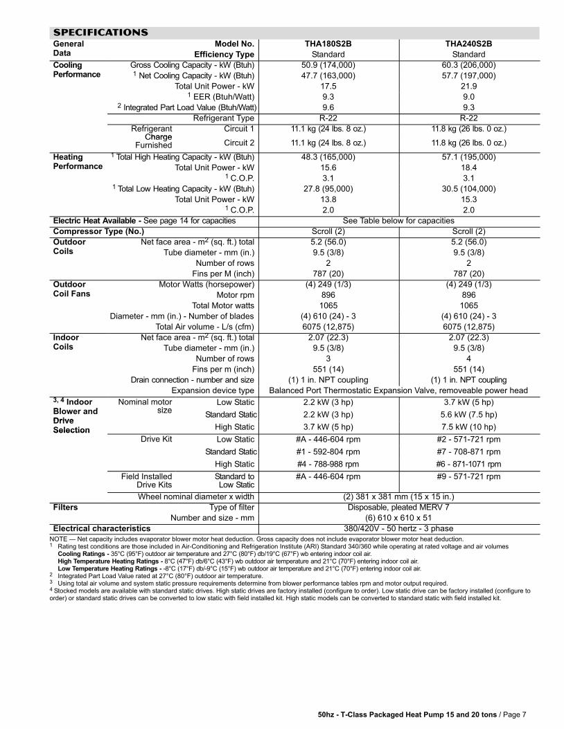
SPECIFICATIONS GeneralD
Model No. THA180S2B THA240S2BData Efficiency Type Standard Standard
CoolingP f
Gross Cooling Capacity − kW (Btuh) 50.9 (174,000) 60.3 (206,000)gPerformance 1 Net Cooling Capacity − kW (Btuh) 47.7 (163,000) 57.7 (197,000)
Total Unit Power − kW 17.5 21.91 EER (Btuh/Watt) 9.3 9.0
2 Integrated Part Load Value (Btuh/Watt) 9.6 9.3
Refrigerant Type R−22 R−22
RefrigerantCharge
Circuit 1 11.1 kg (24 lbs. 8 oz.) 11.8 kg (26 lbs. 0 oz.)Charge
Furnished Circuit 2 11.1 kg (24 lbs. 8 oz.) 11.8 kg (26 lbs. 0 oz.)
HeatingP f
1 Total High Heating Capacity − kW (Btuh) 48.3 (165,000) 57.1 (195,000)gPerformance Total Unit Power − kW 15.6 18.4
1 C.O.P. 3.1 3.11 Total Low Heating Capacity − kW (Btuh) 27.8 (95,000) 30.5 (104,000)
Total Unit Power − kW 13.8 15.31 C.O.P. 2.0 2.0
Electric Heat Available − See page 14 for capacities See Table below for capacities
Compressor Type (No.) Scroll (2) Scroll (2)
OutdoorC
Net face area − m2 (sq. ft.) total 5.2 (56.0) 5.2 (56.0)Coils Tube diameter − mm (in.) 9.5 (3/8) 9.5 (3/8)
Number of rows 2 2
Fins per M (inch) 787 (20) 787 (20)
OutdoorC il F
Motor Watts (horsepower) (4) 249 (1/3) (4) 249 (1/3)Coil Fans Motor rpm 896 896
Total Motor watts 1065 1065
Diameter − mm (in.) − Number of blades (4) 610 (24) − 3 (4) 610 (24) − 3
Total Air volume − L/s (cfm) 6075 (12,875) 6075 (12,875)
IndoorC
Net face area − m2 (sq. ft.) total 2.07 (22.3) 2.07 (22.3)Coils Tube diameter − mm (in.) 9.5 (3/8) 9.5 (3/8)
Number of rows 3 4
Fins per m (inch) 551 (14) 551 (14)
Drain connection − number and size (1) 1 in. NPT coupling (1) 1 in. NPT coupling
Expansion device type Balanced Port Thermostatic Expansion Valve, removeable power head3, 4 IndoorBl d
Nominal motorsize
Low Static 2.2 kW (3 hp) 3.7 kW (5 hp)Blower andDrive
sizeStandard Static 2.2 kW (3 hp) 5.6 kW (7.5 hp)
DriveSelection High Static 3.7 kW (5 hp) 7.5 kW (10 hp)Selection
Drive Kit Low Static #A − 446−604 rpm #2 − 571−721 rpm
Standard Static #1 − 592−804 rpm #7 − 708−871 rpm
High Static #4 − 788−988 rpm #6 − 871−1071 rpm
Field InstalledDrive Kits
Standard toLow Static
#A − 446−604 rpm #9 − 571−721 rpm
Wheel�nominal�diameter�x�width (2) 381 x 381 mm (15 x 15 in.)
Filters Type of filter Disposable, pleated MERV 7
Number and size − mm (6) 610 x 610 x 51
Electrical characteristics 380/420V − 50 hertz − 3 phase
NOTE � Net capacity includes evaporator blower motor heat deduction. Gross capacity does not include evaporator blower motor heat deduction.1 Rating test conditions are those included in Air−Conditioning and Refrigeration Institute (ARI) Standard 340/360 while operating at rated voltage and air volumes
Cooling Ratings − 35°C (95°F) outdoor air temperature and 27°C (80°F) db/19°C (67°F) wb entering indoor coil air.High Temperature Heating Ratings − 8°C (47°F) db/6°C (43°F) wb outdoor air temperature and 21°C (70°F) entering indoor coil air.Low Temperature Heating Ratings − -8°C (17°F) db/-9°C (15°F) wb outdoor air temperature and 21°C (70°F) entering indoor coil air.
2 Integrated Part Load Value rated at 27°C (80°F) outdoor air temperature.3 Using total air volume and system static pressure requirements determine from blower performance tables rpm and motor output required. 4 Stocked models are available with standard static drives. High static drives are factory installed (configure to order). Low static drive can be factory installed (configure toorder) or standard static drives can be converted to low static with field installed kit. High static models can be converted to standard static with field installed kit.
50hz − T−Class Packaged Heat Pump 15 and 20 tons / Page 8
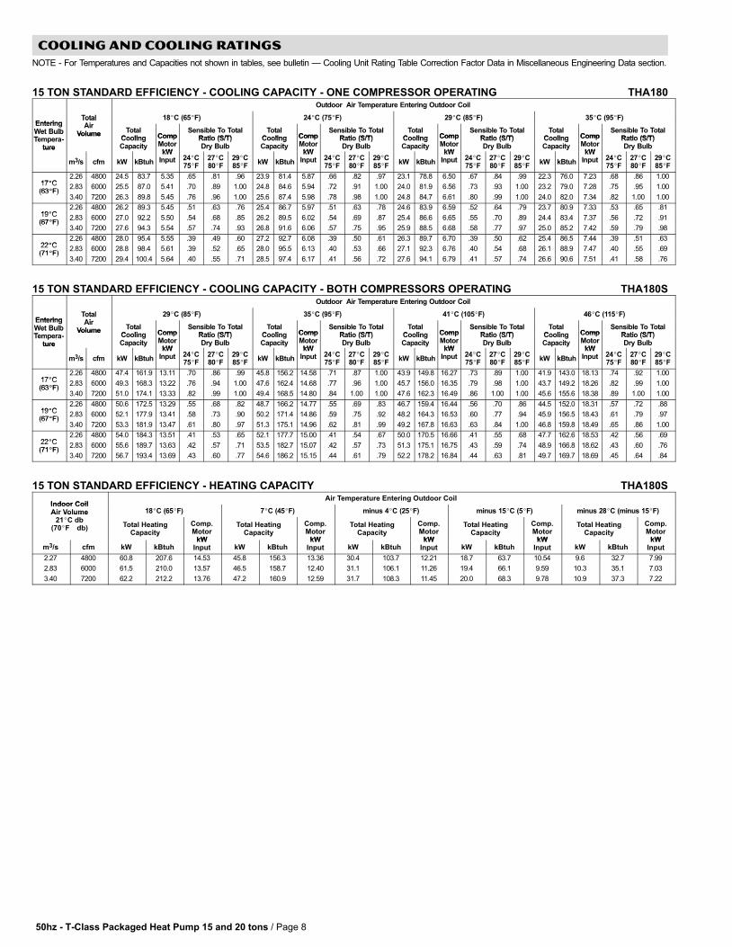
COOLING AND COOLING RATINGS
NOTE − For Temperatures and Capacities not shown in tables, see bulletin � Cooling Unit Rating Table Correction Factor Data in Miscellaneous Engineering Data section.
15 TON STANDARD EFFICIENCY − COOLING CAPACITY − ONE COMPRESSOR OPERATING THA180Outdoor Air Temperature Entering Outdoor Coil
EnteringTotalAi
18�C (65�F) 24�C (75�F) 29�C (85�F) 35�C (95�F)EnteringWet BulbT
TotalAir
Volume TotalCooling Comp
Sensible To TotalRatio (S/T)
TotalCooling Comp
Sensible To TotalRatio (S/T)
TotalCooling Comp
Sensible To TotalRatio (S/T)
TotalCooling Comp
Sensible To TotalRatio (S/T)
Wet BulbTempera-
ture
VolumeCoolingCapacity
CompMotor
kW
Ratio (S/T)Dry Bulb
CoolingCapacity
CompMotor
kW
Ratio (S/T)Dry Bulb
CoolingCapacity
CompMotor
kW
Ratio (S/T)Dry Bulb
CoolingCapacity
CompMotor
kW
Ratio (S/T)Dry Bulbture
m3/s cfm kW kBtuh
kWInput 24�C
75�F27�C80�F
29�C85�F
kW kBtuh
kWInput 24�C
75�F27�C80�F
29�C85�F
kW kBtuh
kWInput 24�C
75�F27�C80�F
29�C85�F
kW kBtuh
kWInput 24�C
75�F27�C80�F
29�C85�F
17�C2.26 4800 24.5 83.7 5.35 .65 .81 .96 23.9 81.4 5.87 .66 .82 .97 23.1 78.8 6.50 .67 .84 .99 22.3 76.0 7.23 .68 .86 1.00
17�C(63�F)
2.83 6000 25.5 87.0 5.41 .70 .89 1.00 24.8 84.6 5.94 .72 .91 1.00 24.0 81.9 6.56 .73 .93 1.00 23.2 79.0 7.28 .75 .95 1.00(63�F)
3.40 7200 26.3 89.8 5.45 .76 .96 1.00 25.6 87.4 5.98 .78 .98 1.00 24.8 84.7 6.61 .80 .99 1.00 24.0 82.0 7.34 .82 1.00 1.00
19�C2.26 4800 26.2 89.3 5.45 .51 .63 .76 25.4 86.7 5.97 .51 .63 .78 24.6 83.9 6.59 .52 .64 .79 23.7 80.9 7.33 .53 .65 .81
19�C(67�F)
2.83 6000 27.0 92.2 5.50 .54 .68 .85 26.2 89.5 6.02 .54 .69 .87 25.4 86.6 6.65 .55 .70 .89 24.4 83.4 7.37 .56 .72 .91(67�F)
3.40 7200 27.6 94.3 5.54 .57 .74 .93 26.8 91.6 6.06 .57 .75 .95 25.9 88.5 6.68 .58 .77 .97 25.0 85.2 7.42 .59 .79 .98
22�C2.26 4800 28.0 95.4 5.55 .39 .49 .60 27.2 92.7 6.08 .39 .50 .61 26.3 89.7 6.70 .39 .50 .62 25.4 86.5 7.44 .39 .51 .63
22�C(71�F)
2.83 6000 28.8 98.4 5.61 .39 .52 .65 28.0 95.5 6.13 .40 .53 .66 27.1 92.3 6.76 .40 .54 .68 26.1 88.9 7.47 .40 .55 .69(71�F)
3.40 7200 29.4 100.4 5.64 .40 .55 .71 28.5 97.4 6.17 .41 .56 .72 27.6 94.1 6.79 .41 .57 .74 26.6 90.6 7.51 .41 .58 .76
15 TON STANDARD EFFICIENCY − COOLING CAPACITY − BOTH COMPRESSORS OPERATING THA180SOutdoor Air Temperature Entering Outdoor Coil
EnteringTotalAi
29�C (85�F) 35�C (95�F) 41�C (105�F) 46�C (115�F)EnteringWet BulbT
TotalAir
Volume TotalCooling Comp
Sensible To TotalRatio (S/T)
TotalCooling Comp
Sensible To TotalRatio (S/T)
TotalCooling Comp
Sensible To TotalRatio (S/T)
TotalCooling Comp
Sensible To TotalRatio (S/T)
Wet BulbTempera-
ture
VolumeCoolingCapacity
CompMotor
kW
Ratio (S/T)Dry Bulb
CoolingCapacity
CompMotor
kW
Ratio (S/T)Dry Bulb
CoolingCapacity
CompMotor
kW
Ratio (S/T)Dry Bulb
CoolingCapacity
CompMotor
kW
Ratio (S/T)Dry Bulbture
m3/s cfm kW kBtuh
kWInput 24�C
75�F27�C80�F
29�C85�F
kW kBtuh
kWInput 24�C
75�F27�C80�F
29�C85�F
kW kBtuh
kWInput 24�C
75�F27�C80�F
29�C85�F
kW kBtuh
kWInput 24�C
75�F27�C80�F
29�C85�F
17�C2.26 4800 47.4 161.9 13.11 .70 .86 .99 45.8 156.2 14.58 .71 .87 1.00 43.9 149.8 16.27 .73 .89 1.00 41.9 143.0 18.13 .74 .92 1.00
17�C(63�F)
2.83 6000 49.3 168.3 13.22 .76 .94 1.00 47.6 162.4 14.68 .77 .96 1.00 45.7 156.0 16.35 .79 .98 1.00 43.7 149.2 18.26 .82 .99 1.00(63�F)
3.40 7200 51.0 174.1 13.33 .82 .99 1.00 49.4 168.5 14.80 .84 1.00 1.00 47.6 162.3 16.49 .86 1.00 1.00 45.6 155.6 18.38 .89 1.00 1.00
19�C2.26 4800 50.6 172.5 13.29 .55 .68 .82 48.7 166.2 14.77 .55 .69 .83 46.7 159.4 16.44 .56 .70 .86 44.5 152.0 18.31 .57 .72 .88
19�C(67�F)
2.83 6000 52.1 177.9 13.41 .58 .73 .90 50.2 171.4 14.86 .59 .75 .92 48.2 164.3 16.53 .60 .77 .94 45.9 156.5 18.43 .61 .79 .97(67�F)
3.40 7200 53.3 181.9 13.47 .61 .80 .97 51.3 175.1 14.96 .62 .81 .99 49.2 167.8 16.63 .63 .84 1.00 46.8 159.8 18.49 .65 .86 1.00
22�C2.26 4800 54.0 184.3 13.51 .41 .53 .65 52.1 177.7 15.00 .41 .54 .67 50.0 170.5 16.66 .41 .55 .68 47.7 162.6 18.53 .42 .56 .69
22�C(71�F)
2.83 6000 55.6 189.7 13.63 .42 .57 .71 53.5 182.7 15.07 .42 .57 .73 51.3 175.1 16.75 .43 .59 .74 48.9 166.8 18.62 .43 .60 .76(71�F)
3.40 7200 56.7 193.4 13.69 .43 .60 .77 54.6 186.2 15.15 .44 .61 .79 52.2 178.2 16.84 .44 .63 .81 49.7 169.7 18.69 .45 .64 .84
15 TON STANDARD EFFICIENCY − HEATING CAPACITY THA180S
Indoor CoilAir Temperature Entering Outdoor Coil
Indoor CoilAir Volume 18�C (65�F) 7�C (45�F) minus 4�C (25�F) minus 15�C (5�F) minus 28�C (minus 15�F)Air Volume
21�C db(70�F db) Total Heating
Capacity
Comp.Motor
kW
Total HeatingCapacity
Comp.Motor
kW
Total HeatingCapacity
Comp.Motor
kW
Total HeatingCapacity
Comp.Motor
kW
Total HeatingCapacity
Comp.Motor
kWm3/s cfm kW kBtuh
kWInput kW kBtuh
kWInput kW kBtuh
kWInput kW kBtuh
kWInput kW kBtuh
kWInput
2.27 4800 60.8 207.6 14.53 45.8 156.3 13.36 30.4 103.7 12.21 18.7 63.7 10.54 9.6 32.7 7.99
2.83 6000 61.5 210.0 13.57 46.5 158.7 12.40 31.1 106.1 11.26 19.4 66.1 9.59 10.3 35.1 7.03
3.40 7200 62.2 212.2 13.76 47.2 160.9 12.59 31.7 108.3 11.45 20.0 68.3 9.78 10.9 37.3 7.22
50hz − T−Class Packaged Heat Pump 15 and 20 tons / Page 9
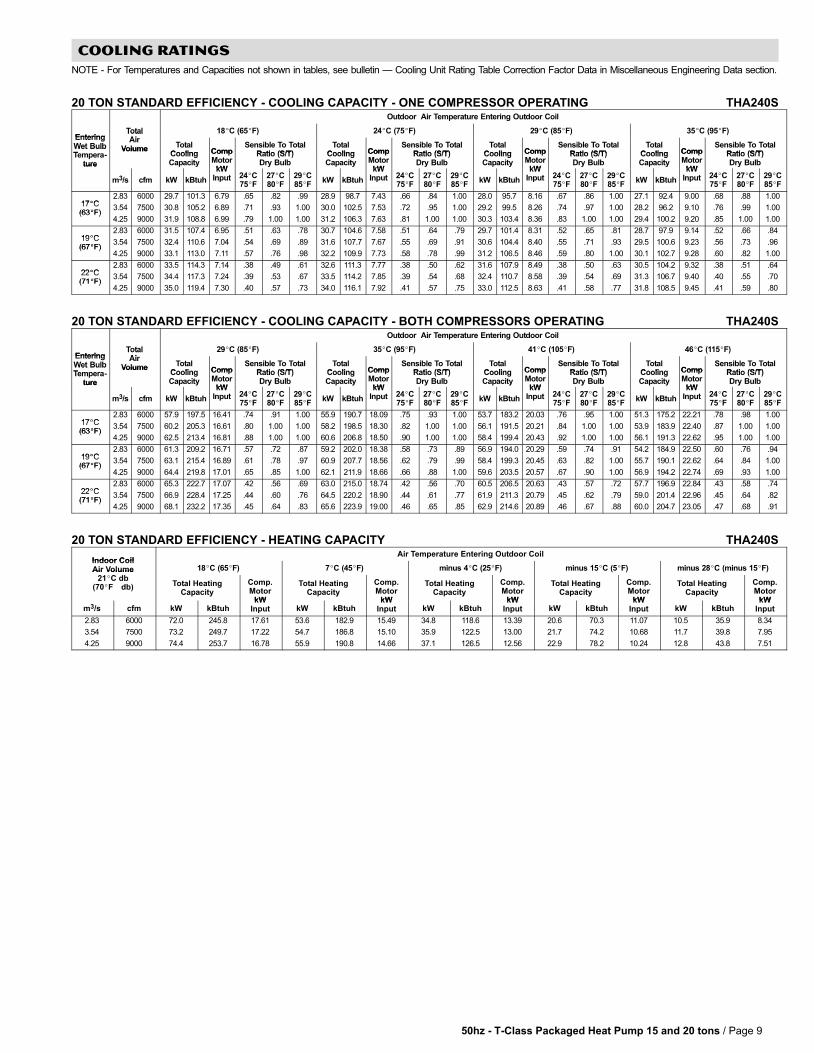
COOLING RATINGS
NOTE − For Temperatures and Capacities not shown in tables, see bulletin � Cooling Unit Rating Table Correction Factor Data in Miscellaneous Engineering Data section.
20 TON STANDARD EFFICIENCY − COOLING CAPACITY − ONE COMPRESSOR OPERATING THA240SOutdoor Air Temperature Entering Outdoor Coil
EnteringTotalAi
18�C (65�F) 24�C (75�F) 29�C (85�F) 35�C (95�F)EnteringWet BulbT
TotalAir
Volume TotalCooling Comp
Sensible To TotalRatio (S/T)
TotalCooling Comp
Sensible To TotalRatio (S/T)
TotalCooling Comp
Sensible To TotalRatio (S/T)
TotalCooling Comp
Sensible To TotalRatio (S/T)
Wet BulbTempera-
ture
VolumeCoolingCapacity
CompMotor
kW
Ratio (S/T)Dry Bulb
CoolingCapacity
CompMotor
kW
Ratio (S/T)Dry Bulb
CoolingCapacity
CompMotor
kW
Ratio (S/T)Dry Bulb
CoolingCapacity
CompMotor
kW
Ratio (S/T)Dry Bulbture
m3/s cfm kW kBtuh
kWInput 24�C
75�F27�C80�F
29�C85�F
kW kBtuh
kWInput 24�C
75�F27�C80�F
29�C85�F
kW kBtuh
kWInput 24�C
75�F27�C80�F
29�C85�F
kW kBtuh
kWInput 24�C
75�F27�C80�F
29�C85�F
17�C2.83 6000 29.7 101.3 6.79 .65 .82 .99 28.9 98.7 7.43 .66 .84 1.00 28.0 95.7 8.16 .67 .86 1.00 27.1 92.4 9.00 .68 .88 1.00
17�C(63�F)
3.54 7500 30.8 105.2 6.89 .71 .93 1.00 30.0 102.5 7.53 .72 .95 1.00 29.2 99.5 8.26 .74 .97 1.00 28.2 96.2 9.10 .76 .99 1.00(63�F)
4.25 9000 31.9 108.8 6.99 .79 1.00 1.00 31.2 106.3 7.63 .81 1.00 1.00 30.3 103.4 8.36 .83 1.00 1.00 29.4 100.2 9.20 .85 1.00 1.00
19�C2.83 6000 31.5 107.4 6.95 .51 .63 .78 30.7 104.6 7.58 .51 .64 .79 29.7 101.4 8.31 .52 .65 .81 28.7 97.9 9.14 .52 .66 .84
19�C(67�F)
3.54 7500 32.4 110.6 7.04 .54 .69 .89 31.6 107.7 7.67 .55 .69 .91 30.6 104.4 8.40 .55 .71 .93 29.5 100.6 9.23 .56 .73 .96(67�F)
4.25 9000 33.1 113.0 7.11 .57 .76 .98 32.2 109.9 7.73 .58 .78 .99 31.2 106.5 8.46 .59 .80 1.00 30.1 102.7 9.28 .60 .82 1.00
22�C2.83 6000 33.5 114.3 7.14 .38 .49 .61 32.6 111.3 7.77 .38 .50 .62 31.6 107.9 8.49 .38 .50 .63 30.5 104.2 9.32 .38 .51 .64
22�C(71�F)
3.54 7500 34.4 117.3 7.24 .39 .53 .67 33.5 114.2 7.85 .39 .54 .68 32.4 110.7 8.58 .39 .54 .69 31.3 106.7 9.40 .40 .55 .70(71�F)
4.25 9000 35.0 119.4 7.30 .40 .57 .73 34.0 116.1 7.92 .41 .57 .75 33.0 112.5 8.63 .41 .58 .77 31.8 108.5 9.45 .41 .59 .80
20 TON STANDARD EFFICIENCY − COOLING CAPACITY − BOTH COMPRESSORS OPERATING THA240SOutdoor Air Temperature Entering Outdoor Coil
EnteringTotalAi
29�C (85�F) 35�C (95�F) 41�C (105�F) 46�C (115�F)EnteringWet BulbT
TotalAir
Volume TotalCooling Comp
Sensible To TotalRatio (S/T)
TotalCooling Comp
Sensible To TotalRatio (S/T)
TotalCooling Comp
Sensible To TotalRatio (S/T)
TotalCooling Comp
Sensible To TotalRatio (S/T)
Wet BulbTempera-
ture
VolumeCoolingCapacity
CompMotor
kW
Ratio (S/T)Dry Bulb
CoolingCapacity
CompMotor
kW
Ratio (S/T)Dry Bulb
CoolingCapacity
CompMotor
kW
Ratio (S/T)Dry Bulb
CoolingCapacity
CompMotor
kW
Ratio (S/T)Dry Bulbture
m3/s cfm kW kBtuh
kWInput 24�C
75�F27�C80�F
29�C85�F
kW kBtuh
kWInput 24�C
75�F27�C80�F
29�C85�F
kW kBtuh
kWInput 24�C
75�F27�C80�F
29�C85�F
kW kBtuh
kWInput 24�C
75�F27�C80�F
29�C85�F
17�C2.83 6000 57.9 197.5 16.41 .74 .91 1.00 55.9 190.7 18.09 .75 .93 1.00 53.7 183.2 20.03 .76 .95 1.00 51.3 175.2 22.21 .78 .98 1.00
17�C(63�F)
3.54 7500 60.2 205.3 16.61 .80 1.00 1.00 58.2 198.5 18.30 .82 1.00 1.00 56.1 191.5 20.21 .84 1.00 1.00 53.9 183.9 22.40 .87 1.00 1.00(63�F)
4.25 9000 62.5 213.4 16.81 .88 1.00 1.00 60.6 206.8 18.50 .90 1.00 1.00 58.4 199.4 20.43 .92 1.00 1.00 56.1 191.3 22.62 .95 1.00 1.00
19�C2.83 6000 61.3 209.2 16.71 .57 .72 .87 59.2 202.0 18.38 .58 .73 .89 56.9 194.0 20.29 .59 .74 .91 54.2 184.9 22.50 .60 .76 .94
19�C(67�F)
3.54 7500 63.1 215.4 16.89 .61 .78 .97 60.9 207.7 18.56 .62 .79 .99 58.4 199.3 20.45 .63 .82 1.00 55.7 190.1 22.62 .64 .84 1.00(67�F)
4.25 9000 64.4 219.8 17.01 .65 .85 1.00 62.1 211.9 18.66 .66 .88 1.00 59.6 203.5 20.57 .67 .90 1.00 56.9 194.2 22.74 .69 .93 1.00
22�C2.83 6000 65.3 222.7 17.07 .42 .56 .69 63.0 215.0 18.74 .42 .56 .70 60.5 206.5 20.63 .43 .57 .72 57.7 196.9 22.84 .43 .58 .74
22�C(71�F)
3.54 7500 66.9 228.4 17.25 .44 .60 .76 64.5 220.2 18.90 .44 .61 .77 61.9 211.3 20.79 .45 .62 .79 59.0 201.4 22.96 .45 .64 .82(71�F)
4.25 9000 68.1 232.2 17.35 .45 .64 .83 65.6 223.9 19.00 .46 .65 .85 62.9 214.6 20.89 .46 .67 .88 60.0 204.7 23.05 .47 .68 .91
20 TON STANDARD EFFICIENCY − HEATING CAPACITY THA240S
Indoor CoilAir Temperature Entering Outdoor Coil
Indoor CoilAir Volume 18�C (65�F) 7�C (45�F) minus 4�C (25�F) minus 15�C (5�F) minus 28�C (minus 15�F)Air Volume
21�C db(70�F db) Total Heating
Capacity
Comp.Motor
kW
Total HeatingCapacity
Comp.Motor
kW
Total HeatingCapacity
Comp.Motor
kW
Total HeatingCapacity
Comp.Motor
kW
Total HeatingCapacity
Comp.Motor
kWm3/s cfm kW kBtuh
kWInput kW kBtuh
kWInput kW kBtuh
kWInput kW kBtuh
kWInput kW kBtuh
kWInput
2.83 6000 72.0 245.8 17.61 53.6 182.9 15.49 34.8 118.6 13.39 20.6 70.3 11.07 10.5 35.9 8.34
3.54 7500 73.2 249.7 17.22 54.7 186.8 15.10 35.9 122.5 13.00 21.7 74.2 10.68 11.7 39.8 7.95
4.25 9000 74.4 253.7 16.78 55.9 190.8 14.66 37.1 126.5 12.56 22.9 78.2 10.24 12.8 43.8 7.51

50hz − T−Class Packaged Heat Pump 15 and 20 tons / Page 10
BLOWER DATA THA180
BLOWER TABLE INCLUDES RESISTANCE FOR BASE UNIT WITH WET INDOOR COIL & AIR FILTERS IN PLACE.FOR ALL UNITS ADD: Any field installed accessories air resistance (duct resistance, diffuser, etc.). See page 12Then determine from table the blower motor output and drive required.
100 to 375 Pa THA180Air
VolumeExternal Static (Pa)
VolumeL/s 100 125 150 175 200 225 250 275 300 325 350 375L/s
RPM BHP RPM BHP RPM BHP RPM BHP RPM BHP RPM BHP RPM BHP RPM BHP RPM BHP RPM BHP RPM BHP RPM BHP
Low − 2.2kW, DriveKit A
Standard Static − 2.2 kW (3 hp), Drive Kit 1 High Static − 3.7 kW (5 hp), Drive Kit 4
2265 577 1.13 620 1.31 662 1.48 702 1.66 742 1.83 777 2.01 811 2.18 842 2.36 872 2.54 902 2.72 932 2.89 960 3.07
2360 585 1.25 628 1.43 670 1.60 710 1.78 750 1.95 783 2.13 815 2.30 848 2.50 880 2.70 910 2.88 940 3.05 968 3.23
2595 605 1.45 648 1.65 690 1.85 728 2.05 765 2.25 800 2.45 835 2.65 865 2.85 895 3.05 925 3.25 955 3.45 983 3.65
2830 630 1.75 670 1.95 710 2.15 748 2.38 785 2.60 818 2.83 850 3.05 880 3.25 910 3.45 940 3.68 970 3.90 998 4.13
3065 650 2.05 690 2.28 730 2.50 768 2.75 805 3.00 838 3.23 870 3.45 900 3.70 930 3.95 958 4.18 985 4.40 1013 4.63
3305 675 2.35 715 2.63 755 2.90 790 3.15 825 3.40 858 3.68 890 3.95 920 4.20 950 4.45 978 4.70 1005 4.95 1030 5.18
3540 687 2.55 725 2.81 763 3.06 798 3.33 833 3.60 866 3.86 898 4.11 926 4.36 954 4.61 984 4.90 1013 5.19 1038 5.44
400 to 650 Pa THA180Air
VolumeExternal Static (Pa)
Volumecfm 400 425 450 475 500 525 550 575 600 625 650cfm
RPM BHP RPM BHP RPM BHP RPM BHP RPM BHP RPM BHP RPM BHP RPM BHP RPM BHP RPM BHP RPM BHP
High − 3.7kW, DriveKit 4
Field Furnished Drive
2265 987 3.24 1014 3.42 1041 3.60 1064 3.78 1087 3.95 1112 4.13 1136 4.30 1159 4.50 1181 4.70 1204 4.88 1226 5.06
2360 995 3.40 1020 3.60 1045 3.80 1070 3.98 1095 4.15 1118 4.33 1140 4.50 1163 4.70 1185 4.90 1208 5.10 1230 5.30
2595 1010 3.85 1035 4.05 1060 4.25 1085 4.48 1110 4.70 1133 4.90 1155 5.10 1178 5.30 1200 5.50 1220 5.70 1240 5.90
2830 1025 4.35 1050 4.58 1075 4.80 1098 5.00 1120 5.20 1145 5.43 1170 5.65 1193 5.88 1215 6.10 1235 6.33 1255 6.55
3065 1040 4.85 1065 5.10 1090 5.35 1115 5.60 1140 5.85 1163 6.08 1185 6.30 1205 6.53 1225 6.75 1248 7.00 1270 7.25
3305 1055 5.40 1080 5.68 1105 5.95 1130 6.20 1155 6.45 1178 6.70 1200 6.95 1220 7.20 1240 7.45 1263 7.73 1285 8.00
3540 1063 5.68 1088 5.94 1113 6.19 1136 6.44 1159 6.69 1182 6.96 1204 7.23 1226 7.50 1248 7.77 1269 8.03 1289 8.28
AIR RESISTANCE (Pa) − Options
Air Volume − L/s Electric Heat Economizer Horizontal Roof Curb MERV 11 Filter
2265 − − − − − − 20 2
2360 − − − − − − 20 2
2595 − − − − − − 25 5
2830 2 − − − 27 5
3065 2 5 32 5
3305 2 10 37 7
3540 2 12 40 7
50hz − T−Class Packaged Heat Pump 15 and 20 tons / Page 11
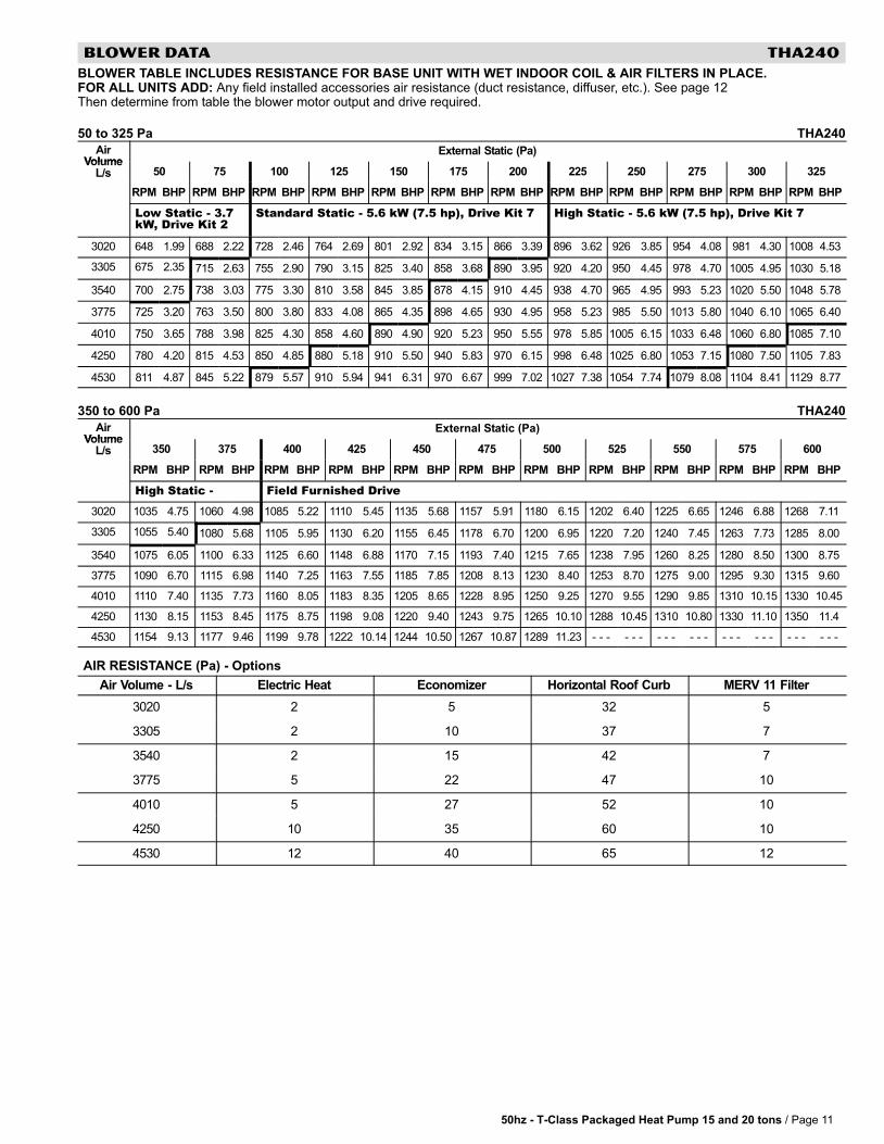
BLOWER DATA THA240
BLOWER TABLE INCLUDES RESISTANCE FOR BASE UNIT WITH WET INDOOR COIL & AIR FILTERS IN PLACE.FOR ALL UNITS ADD: Any field installed accessories air resistance (duct resistance, diffuser, etc.). See page 12Then determine from table the blower motor output and drive required.
50 to 325 Pa THA240
AirVolume
External Static (Pa)Volume
L/s 50 75 100 125 150 175 200 225 250 275 300 325
RPM BHP RPM BHP RPM BHP RPM BHP RPM BHP RPM BHP RPM BHP RPM BHP RPM BHP RPM BHP RPM BHP RPM BHP
Low Static − 3.7kW, Drive Kit 2
Standard Static − 5.6 kW (7.5 hp), Drive Kit 7 High Static − 5.6 kW (7.5 hp), Drive Kit 7
3020 648 1.99 688 2.22 728 2.46 764 2.69 801 2.92 834 3.15 866 3.39 896 3.62 926 3.85 954 4.08 981 4.30 1008 4.53
3305 675 2.35 715 2.63 755 2.90 790 3.15 825 3.40 858 3.68 890 3.95 920 4.20 950 4.45 978 4.70 1005 4.95 1030 5.18
3540 700 2.75 738 3.03 775 3.30 810 3.58 845 3.85 878 4.15 910 4.45 938 4.70 965 4.95 993 5.23 1020 5.50 1048 5.78
3775 725 3.20 763 3.50 800 3.80 833 4.08 865 4.35 898 4.65 930 4.95 958 5.23 985 5.50 1013 5.80 1040 6.10 1065 6.40
4010 750 3.65 788 3.98 825 4.30 858 4.60 890 4.90 920 5.23 950 5.55 978 5.85 1005 6.15 1033 6.48 1060 6.80 1085 7.10
4250 780 4.20 815 4.53 850 4.85 880 5.18 910 5.50 940 5.83 970 6.15 998 6.48 1025 6.80 1053 7.15 1080 7.50 1105 7.83
4530 811 4.87 845 5.22 879 5.57 910 5.94 941 6.31 970 6.67 999 7.02 1027 7.38 1054 7.74 1079 8.08 1104 8.41 1129 8.77
350 to 600 Pa THA240
AirVolume
External Static (Pa)Volume
L/s 350 375 400 425 450 475 500 525 550 575 600
RPM BHP RPM BHP RPM BHP RPM BHP RPM BHP RPM BHP RPM BHP RPM BHP RPM BHP RPM BHP RPM BHP
High Static − Field Furnished Drive
3020 1035 4.75 1060 4.98 1085 5.22 1110 5.45 1135 5.68 1157 5.91 1180 6.15 1202 6.40 1225 6.65 1246 6.88 1268 7.11
3305 1055 5.40 1080 5.68 1105 5.95 1130 6.20 1155 6.45 1178 6.70 1200 6.95 1220 7.20 1240 7.45 1263 7.73 1285 8.00
3540 1075 6.05 1100 6.33 1125 6.60 1148 6.88 1170 7.15 1193 7.40 1215 7.65 1238 7.95 1260 8.25 1280 8.50 1300 8.75
3775 1090 6.70 1115 6.98 1140 7.25 1163 7.55 1185 7.85 1208 8.13 1230 8.40 1253 8.70 1275 9.00 1295 9.30 1315 9.60
4010 1110 7.40 1135 7.73 1160 8.05 1183 8.35 1205 8.65 1228 8.95 1250 9.25 1270 9.55 1290 9.85 1310 10.15 1330 10.45
4250 1130 8.15 1153 8.45 1175 8.75 1198 9.08 1220 9.40 1243 9.75 1265 10.10 1288 10.45 1310 10.80 1330 11.10 1350 11.4
4530 1154 9.13 1177 9.46 1199 9.78 1222 10.14 1244 10.50 1267 10.87 1289 11.23 − − − − − − − − − − − − − − − − − − − − − − − −
AIR RESISTANCE (Pa) − Options
Air Volume − L/s Electric Heat Economizer Horizontal Roof Curb MERV 11 Filter
3020 2 5 32 5
3305 2 10 37 7
3540 2 15 42 7
3775 5 22 47 10
4010 5 27 52 10
4250 10 35 60 10
4530 12 40 65 12
50hz − T−Class Packaged Heat Pump 15 and 20 tons / Page 12
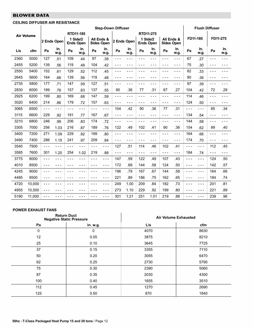
BLOWER DATA
CEILING DIFFUSER AIR RESISTANCE
Step-Down Diffuser Flush Diffuser
Air VolumeRTD11−185 RTD11−275
Air Volume
2 Ends Open1 Side/2
Ends OpenAll Ends &Sides Open 2 Ends Open
1 Side/2Ends Open
All Ends &Sides Open
FD11−185 FD11−275
L/s cfm Pain.
w.g.Pa
in.w.g.
Pain.
w.g.Pa
in.w.g.
Pain.
w.g.Pa
in.w.g.
Pain.
w.g.Pa
in.w.g.
2360 5000 127 .51 109 .44 97 .39 − − − − − − − − − − − − − − − − − − 67 .27 − − − − − −
2455 5200 139 .56 119 .48 104 .42 − − − − − − − − − − − − − − − − − − 75 .30 − − − − − −
2550 5400 152 .61 129 .52 112 .45 − − − − − − − − − − − − − − − − − − 82 .33 − − − − − −
2645 5600 164 .66 139 .56 119 .48 − − − − − − − − − − − − − − − − − − 90 .36 − − − − − −
2735 5800 177 .71 147 .59 127 .51 − − − − − − − − − − − − − − − − − − 97 .39 − − − − − −
2830 6000 189 .76 157 .63 137 .55 90 .36 77 .31 67 .27 104 .42 72 .29
2925 6200 199 .80 169 .68 147 .59 − − − − − − − − − − − − − − − − − − 114 .46 − − − − − −
3020 6400 214 .86 179 .72 157 .63 − − − − − − − − − − − − − − − − − − 124 .50 − − − − − −
3065 6500 − − − − − − − − − − − − − − − − − − 104 .42 90 .36 77 .31 − − − − − − 85 .34
3115 6600 229 .92 191 .77 167 .67 − − − − − − − − − − − − − − − − − − 134 .54 − − − − − −
3210 6800 246 .99 206 .83 174 .72 − − − − − − − − − − − − − − − − − − 144 .58 − − − − − −
3305 7000 256 1.03 216 .87 189 .76 122 .49 102 .41 90 .36 154 .62 99 .40
3400 7200 271 1.09 229 .92 199 .80 − − − − − − − − − − − − − − − − − − 164 .66 − − − − − −
3490 7400 286 1.15 241 .97 209 .84 − − − − − − − − − − − − − − − − − − 174 .70 − − − − − −
3540 7500 − − − − − − − − − − − − − − − − − − 127 .51 114 .46 102 .41 − − − − − − 112 .45
3585 7600 301 1.20 254 1.02 219 .88 − − − − − − − − − − − − − − − − − − 184 .74 − − − − − −
3775 8000 − − − − − − − − − − − − − − − − − − 147 .59 122 .49 107 .43 − − − − − − 124 .50
4010 8500 − − − − − − − − − − − − − − − − − − 172 .69 144 .58 124 .50 − − − − − − 142 .57
4245 9000 − − − − − − − − − − − − − − − − − − 196 .79 167 .67 144 .58 − − − − − − 164 .66
4485 9500 − − − − − − − − − − − − − − − − − − 221 .89 186 .75 162 .65 − − − − − − 184 .74
4720 10,000 − − − − − − − − − − − − − − − − − − 249 1.00 209 .84 182 .73 − − − − − − 201 .81
4955 10,500 − − − − − − − − − − − − − − − − − − 273 1.10 229 .92 199 .80 − − − − − − 221 .89
5190 11,000 − − − − − − − − − − − − − − − − − − 301 1.21 251 1.01 219 .88 − − − − − − 239 .96
POWER EXHAUST FANS
Return DuctNegative Static Pressure
Air Volume Exhausted
Pa in. w.g. L/s cfm
0 0 4070 8630
12 0.05 3875 8210
25 0.10 3645 7725
37 0.15 3355 7110
50 0.20 3055 6470
62 0.25 2730 5790
75 0.30 2390 5060
87 0.35 2030 4300
100 0.40 1655 3510
112 0.45 1270 2690
125 0.50 870 1840
50hz − T−Class Packaged Heat Pump 15 and 20 tons / Page 13
BLOWER DATA
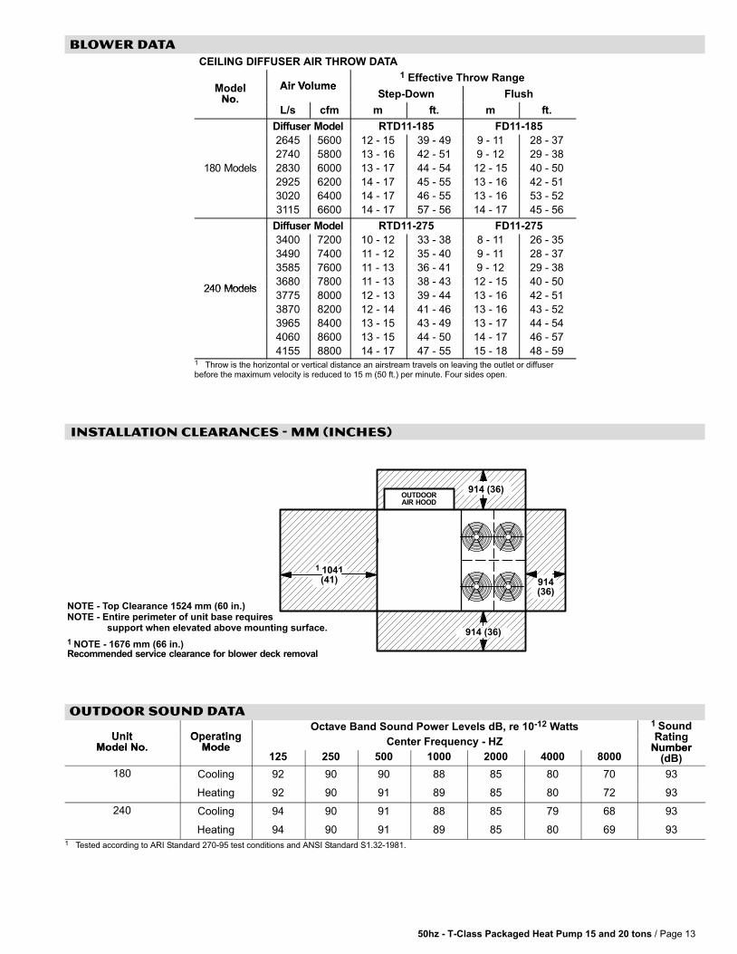
CEILING DIFFUSER AIR THROW DATA
M d l Air Volume1 Effective Throw Range
ModelNo.
Air VolumeStep-Down Flush
No.L/s cfm m ft. m ft.
Diffuser Model RTD11−185 FD11−185
2645 5600 12 − 15 39 − 49 9 − 11 28 − 37
2740 5800 13 − 16 42 − 51 9 − 12 29 − 38
180 Models 2830 6000 13 − 17 44 − 54 12 − 15 40 − 50
2925 6200 14 − 17 45 − 55 13 − 16 42 − 51
3020 6400 14 − 17 46 − 55 13 − 16 53 − 52
3115 6600 14 − 17 57 − 56 14 − 17 45 − 56
Diffuser Model RTD11−275 FD11−275
3400 7200 10 − 12 33 − 38 8 − 11 26 − 35
3490 7400 11 − 12 35 − 40 9 − 11 28 − 37
3585 7600 11 − 13 36 − 41 9 − 12 29 − 38
240 Models3680 7800 11 − 13 38 − 43 12 − 15 40 − 50
240 Models3775 8000 12 − 13 39 − 44 13 − 16 42 − 51
3870 8200 12 − 14 41 − 46 13 − 16 43 − 52
3965 8400 13 − 15 43 − 49 13 − 17 44 − 54
4060 8600 13 − 15 44 − 50 14 − 17 46 − 57
4155 8800 14 − 17 47 − 55 15 − 18 48 − 591 Throw is the horizontal or vertical distance an airstream travels on leaving the outlet�or diffuserbefore the maximum velocity is reduced to 15 m (50 ft.) per minute. Four sides open.
INSTALLATION CLEARANCES − MM (INCHES)
OUTDOORAIR HOOD
914 (36)
914(36)
914 (36)
1 1041(41)
1 NOTE − 1676 mm (66 in.)Recommended service clearance for blower deck removal
NOTE − Top Clearance 1524 mm (60 in.)NOTE − Entire perimeter of unit base requires support when elevated above mounting surface.
OUTDOOR SOUND DATA
Unit OperatingOctave Band Sound Power Levels dB, re 10−12 Watts 1 Sound
RatingUnitModel No.
OperatingMode
Center Frequency − HZ RatingNumberModel No. Mode
125 250 500 1000 2000 4000 8000Number
(dB)
180 Cooling 92 90 90 88 85 80 70 93
Heating 92 90 91 89 85 80 72 93
240 Cooling 94 90 91 88 85 79 68 93
Heating 94 90 91 89 85 80 69 931 Tested according to ARI Standard 270-95 test conditions and ANSI Standard S1.32-1981.
50hz − T−Class Packaged Heat Pump 15 and 20 tons / Page 14
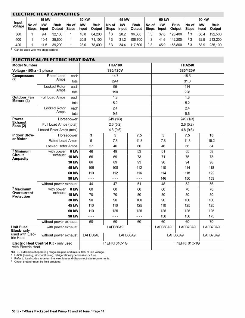
ELECTRIC HEAT CAPACITIES
Input15 kW 30 kW 45 kW 60 kW 90 kW
InputVoltage No of
StepskW
inputBtuh
OutputNo ofSteps
kWinput
BtuhOutput
No ofSteps
kWinput
BtuhOutput
No ofSteps
kWinput
BtuhOutput
No ofSteps
kWinput
BtuhOutput
380 1 9.4 32,100 1 18.8 64,200 1 3 28.2 96,300 1 3 37.6 128,400 1 3 56.4 192,500
400 1 10.4 35,600 1 20.8 71,100 1 3 31.2 106,700 1 3 41.6 142,200 1 3 62.5 213,200
420 1 11.5 39,200 1 23.0 78,400 1 3 34.4 117,600 1 3 45.9 156,800 1 3 68.9 235,1001 Can be used with two stage control.
ELECTRICAL/ELECTRIC HEAT DATA
Model Number THA180 THA240
Voltage − 50hz − 3 phase 380/420V 380/420V
Compressors(2)
Rated LoadAmps
each 14.7 15.5p(2) Amps
total 29.4 31.0
Locked RotorAmps
each 95 114Amps
total 190 228
Outdoor FanMotors (4)
Full Load Amps each 1.3 1.3Motors (4)
p
total 5.2 5.2
Locked RotorAmps
each 2.4 2.4Amps
total 9.6 9.6
PowerExhaust
Horsepower 249 (1/3) 249 (1/3)ExhaustFans (2) Full Load Amps (total) 2.6 (5.2) 2.6 (5.2)Fans (2)
Locked Rotor Amps (total) 4.8 (9.6) 4.8 (9.6)
Indoor Blow-er Motor
Horsepower 3 5 7.5 5 7.5 10er Motor
Rated Load Amps 5 7.8 11.8 7.8 11.8 15.2
Locked Rotor Amps 27 46 66 46 66 841 MinimumCircuit
with powerexhaust
0 kW 46 49 53 51 55 58CircuitAmpacity
pexhaust
15 kW 66 69 73 71 75 78Ampacity
30 kW 86 89 93 90 94 98
45 kW 106 108 112 110 114 118
60 kW 110 112 116 114 118 122
90 kW − − − − − − − − − 146 150 153
without power exhaust 44 47 51 48 52 562 MaximumOvercurrent
with powerexhaust
0 kW 60 60 60 60 70 70OvercurrentProtection
pexhaust
15 kW 70 70 80 80 80 80Protection
30 kW 90 90 100 90 100 100
45 kW 110 110 125 110 125 125
60 kW 110 125 125 125 125 125
90 kW − − − − − − − − − 150 150 175
without power exhaust 50 60 60 60 60 70
Unit FuseBlock− only
with power exhaust LAFB60A9 LAFB60A9 LAFB70A9 LAFB70A9Block onlyused with Elec-tric Heat
without power exhaust LAFB50A8 LAFB60A9 LAFB60A9 LAFB70A9
Electric Heat Control Kit − only usedwith Electric Heat
T1EHKT01C−1G T1EHKT01C−1G
NOTE�− Extremes�of�operating�range�are�plus�and�minus�10%�of�line�voltage.1 HACR (heating, air conditioning, refrigeration) type breaker or fuse.2 Refer�to local�codes�to�determine�wire,�fuse�and�disconnect�size�requirements.3 Circuit breaker must be field provided.
50hz − T−Class Packaged Heat Pump 15 and 20 tons / Page 15
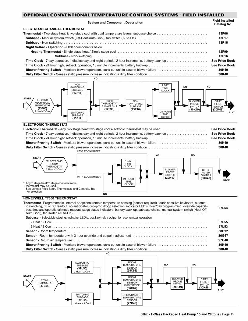
OPTIONAL CONVENTIONAL TEMPERATURE CONTROL SYSTEMS − Field Installed
System and Component DescriptionField InstalledCatalog No.
ELECTRO-MECHANICAL THERMOSTAT
Thermostat − Two stage heat & two stage cool with dual temperature levers, subbase choice . . . . . . . . . . . . . . . . . . . . . . . . . . . . . . . 13F06
Subbase − Manual system switch (Off-Heat-Auto-Cool), fan switch (Auto-On) . . . . . . . . . . . . . . . . . . . . . . . . . . . . . . . . . . . . . . . . . . . 13F17
Subbase − Non-switching . . . . . . . . . . . . . . . . . . . . . . . . . . . . . . . . . . . . . . . . . . . . . . . . . . . . . . . . . . . . . . . . . . . . . . . . . . . . . . . . . . . . . . . . 13F16
Night Setback Operation − Order components below
Heating Thermostat − Single stage heat / Single stage cool . . . . . . . . . . . . . . . . . . . . . . . . . . . . . . . . . . . . . . . . . . . . . . . . . . . . . . . 12F99
Subbase − Non-switching . . . . . . . . . . . . . . . . . . . . . . . . . . . . . . . . . . . . . . . . . . . . . . . . . . . . . . . . . . . . . . . . . . . . . . 13F16
Time Clock − 7 day operation, indicates day and night periods, 2 hour increments, battery back-up . . . . . . . . . . . . . . . . . . . . . . . . . See Price Book
Time Clock − 24 hour night setback operation, 15 minute increments, battery back-up . . . . . . . . . . . . . . . . . . . . . . . . . . . . . . . . . . . . See Price Book
Blower Proving Switch − Monitors blower operation, locks out unit in case of blower failure . . . . . . . . . . . . . . . . . . . . . . . . . . . . . . 30K49
Dirty Filter Switch − Senses static pressure increase indicating a dirty filter condition . . . . . . . . . . . . . . . . . . . . . . . . . . . . . . . . . . . . 30K48
24 HOURTIME
CLOCK
ELECTROMECHANICALTHERMOSTAT
(13F06)2 Heat�−�2 Cool
NONSWITCHINGSUBBASE
(13F16)
SWITCHINGSUBBASE
(13F17)
NIGHTTHERMOSTAT1 Heat/1 Cool
(12F99)
NONSWITCHINGSUBBASE
(13F16)
7 DAYTIME
CLOCK
BLOWERPROVESWITCH
(30K49)
DIRTYFILTER
SWITCH
(30K48)
NO
STOP
START
NO NO
ELECTRONIC THERMOSTAT
Electronic Thermostat − Any two stage heat/ two stage cool electronic thermostat may be used. . . . . . . . . . . . . . . . . . . . . . . . . . . . See Price Book
Time Clock − 7 day operation, indicates day and night periods, 2 hour increments, battery back-up . . . . . . . . . . . . . . . . . . . . . . . . . See Price Book
Time Clock − 24 hour night setback operation, 15 minute increments, battery back-up . . . . . . . . . . . . . . . . . . . . . . . . . . . . . . . . . . . . See Price Book
Blower Proving Switch − Monitors blower operation, locks out unit in case of blower failure . . . . . . . . . . . . . . . . . . . . . . . . . . . . . . 30K49
Dirty Filter Switch − Senses static pressure increase indicating a dirty filter condition . . . . . . . . . . . . . . . . . . . . . . . . . . . . . . . . . . . . 30K48
*ELECTRONICROOM
THERMOSTAT2 Heat�−�2 Cool
24 HOURTIME
CLOCK
7 DAYTIME
CLOCK
BLOWERPROVESWITCH
(30K49)
DIRTYFILTER
SWITCH
(30K48)STOP
STARTNO NO
LESS ECONOMIZER
WITH ECONOMIZER
NO
* Any 2 stage heat/ 2 stage cool electronicthermostat may be used.See Lennox Price Book, Thermostats and Controls, Tab for selection.
HONEYWELL T7300 THERMOSTAT
Thermostat − Programmable, internal or optional remote temperature sensing (sensor required), touch sensitive keyboard, automat-ic switching, �F or �C readout, no anticipator, droop/no droop selection, indicator LED’s, hour/day programming, override capabili-ties, time and operational mode readout, stage status indicators, battery back-up, subbase choice, manual system switch (Heat-Off-Auto-Cool), fan switch (Auto-On) . . . . . . . . . . . . . . . . . . . . . . . . . . . . . . . . . . . . . . . . . . . . . . . . . . . . . . . . . . . . . . . . . . . . . . . . . . . . . . . . . .
37L54
Subbase − Selectable staging, indicator LED’s, auxiliary relay output for economizer operation
2 Heat / 2 Cool . . . . . . . . . . . . . . . . . . . . . . . . . . . . . . . . . . . . . . . . . . . . . . . . . . . . . . . . . . . . . . . . . . . . . . . . . . . . . . . . . . . . . . . . . . . . . . . 37L55
3 Heat / 3 Cool . . . . . . . . . . . . . . . . . . . . . . . . . . . . . . . . . . . . . . . . . . . . . . . . . . . . . . . . . . . . . . . . . . . . . . . . . . . . . . . . . . . . . . . . . . . . . . . 37L53
Sensor − Room temperature . . . . . . . . . . . . . . . . . . . . . . . . . . . . . . . . . . . . . . . . . . . . . . . . . . . . . . . . . . . . . . . . . . . . . . . . . . . . . . . . . . . . . . 58C92
Sensor − Room temperature with 3 hour override and setpoint adjustment . . . . . . . . . . . . . . . . . . . . . . . . . . . . . . . . . . . . . . . . . . . . . . 86G67
Sensor − Return air temperature . . . . . . . . . . . . . . . . . . . . . . . . . . . . . . . . . . . . . . . . . . . . . . . . . . . . . . . . . . . . . . . . . . . . . . . . . . . . . . . . . . 27C40
Blower Proving Switch − Monitors blower operation, locks out unit in case of blower failure . . . . . . . . . . . . . . . . . . . . . . . . . . . . . . 30K49
Dirty Filter Switch − Senses static pressure increase indicating a dirty filter condition . . . . . . . . . . . . . . . . . . . . . . . . . . . . . . . . . . . . 30K48
SWITCHINGSUBBASE
(37L53)3 Heat�−�3 Cool
SWITCHINGSUBBASE
(37L55)2 Heat�−�2 Cool
ROOMTEMPERATURE
SENSORW/OVERRIDE
(86G67)
ROOMTEMPERATURE
SENSOR
(58C92)
RETURN AIRTEMPERATURE
SENSOR
(27C40)
T7300THERMOSTAT
(37L54)
BLOWERPROVESWITCH
(30K49)
DIRTYFILTER
SWITCH
(30K48)
NO
STOP
START
NO NO

50hz − T−Class Packaged Heat Pump 15 and 20 tons / Page 16
WEIGHT DATA
Model NumberNet Shipping
Model Numberkg lbs. kg lbs.
180 Base Unit 1039 2290 1166 2570
180 Max. Unit 1161 2560 1288 2840
240 Base Unit 1060 2340 1186 2615
240 Max. Unit 1179 2600 1304 2875
OPTIONS / ACCESSORIESWeight
kg. lbs.
CEILING DIFFUSERS
Step−Down RTD11−185 178 392p
RTD11−275 183 403
Flush FD11−185 135 289
FD11−275 165 363
Transitions LASRT18 36 80
LASRT21/24 34 75
ECONOMIZER / OUTDOOR AIR / EXHAUST
Economizer T1ECON10C−1 39 86
Barometric Relief
Down−Flow Barometric Relief Dampers LAGED18/24 14 30
Horizontal Barometric Relief Dampers LAGEDH18/24 9 20
Outdoor Air Dampers
Damper Section (down−flow) − Automatic T1DAMP20C−1 24 52
Damper Section (down−flow) − Manual LAOAD18/24 22 49
Outdoor Air Hood (down−flow) C1HOOD10C−1 29 65
Power Exhaust C1PWRE20C−1 28 62
eLECTRIC HEAT
15 kW 27 59
30 kW 27 59
45 kW 35 76
60 kW 35 76
90 kW 38 84
PACKAGING
LTL Packaging (less than truck load) 127 280
ROOF CURBS − STANDARD
Down−Flow
356 mm height LARMF18/36−14 73 160
610 mm height LARMF18/36−24 100 220
Horizontal
660 mm height LARMFH18/24−26 191 420
940 mm height LARMFH18/24−37 263 580
ROOF CURBS − CLIPLOCK 1000
Down−Flow
356 mm height LARMF18/30S−14 74 164
457 mm height LARMF18/30S−18 85 187
610 mm height LARMF18/30S−24 101 222
Horizontal
660 mm height LARMFH18/24S−26 152 335
940 mm height LARMFH18/24S−37 202 445
Base Unit − The unit with NO OPTIONS.Max. Unit − The unit with ALL OPTIONS Installed. (Electric Heat, Economizer, Power Exhaust Fans, Controls)

50hz − T−Class Packaged Heat Pump 15 and 20 tons / Page 17
DIMENSIONS − MM (INCHES)
ModelCORNER WEIGHTS CENTER OF GRAVITY
ModelNumber AA BB CC DD EE FFNumber
kg lbs. kg lbs. kg lbs. kg lbs. mm inch mm inch
180 Base Unit 249 550 200 440 263 580 327 720 1473 58 1003 39−1/2
180 Max. Unit 304 670 231 510 268 590 358 790 1422 56 1067 42
240 Base Unit 259 570 209 460 263 580 331 730 1461 57−1/2 1016 40
240 Max. Unit 313 690 236 520 272 600 358 790 1410 55−1/2 1080 42−1/2
Base Unit − Unit with NO OPTIONS.Max. Unit − Unit with ALL OPTIONS Installed. (Economizer, Power Exhaust Fans, Controls)
BOTTOM POWER ENTRY127 X 203 mm (5 X 8 in.)
BOTTOM SUPPLYAIR OPENINGS
BOTTOM RETURNAIR OPENING
108 (4-1/4)
114(4-1/2)
28(711)
711(28)
102 (4)
102(4)
314(12-3/8)
314(12-3/8) 508 (20) 508 (20)
381 (15)
457 (18)
1537 (60-1/2)
AA BB
CCDD
CENTER OFGRAVITY
EE
FF
SIDE VIEW
TOP VIEW
2289 (90-1/8)
800(31-1/2)
2315 (91-1/8)
83(3-1/4)
3289 (129-1/2)
3264 (128-1/2)
1378(54-1/4)
1295(51)
LIFTING HOLES(For Rigging
Front and Back)CONDENSATE DRAIN
13(1/2)137
(5-3/8)
SIDEELECTRICALKNOCKOUTS
FORKLIFT SLOTS(Front and Left Sides Only)
END VIEW

50hz − T−Class Packaged Heat Pump 15 and 20 tons / Page 18
ACCESSORY DIMENSIONS − mm (INCHES)
1 OPTIONALSTANDARD STATICEXHAUST HOOD
OPTIONAL OUTDOOR AIR HOOD DETAIL
406(16)
OPTIONALOUTDOOR AIR HOOD
Required withEconomizer or
Outdoor Air Damper
1 Field Installed in Return Air Duct for Horizontal Applications.
FRONT VIEW SIDE VIEW
803 (31−5/8)
368(14-1/2)
1 330(13)
165(6-1/2)
1 749 (29−1/2)
NOTE − Two furnished per order no. 1 NOTE − Opening size required in return air duct.
HORIZONTAL BAROMETRIC RELIEF DAMPERS(Field installed in horizontal return air duct adjacent to unit)

50hz − T−Class Packaged Heat Pump 15 and 20 tons / Page 19
ACCESSORY DIMENSIONS − mm (INCHES)
STANDARD ROOF CURBS − DOUBLE DUCT OPENING
25 (1)
51 (2)SECTION A-A
46 (1-13/16)
NOTE � Roof deck may be omitted within confines of curb.
SIDE VIEW
NAILER STRIP(Furnished)
356 (14) LARMF18/36-14610 (24) LARMF18/36-24
CURB RETURNAIR OPENING
CURBSUPPLY AIR
OPENING
TOP VIEW
Fra
me
Openin
gFrame
Opening
432 (17)
533(21)
406 (16)
2594 (102-1/8)
1562 (61-1/2)
2502 (98-1/2)
2188(86-1/8)
2099(82-5/8)
2604 (102-1/2)
46(1-13/16)
AA
NAILER STRIP(Furnished)
19 (3/4) Typ.
356 (14) LARMF18/36-14610 (24) LARMF18/36-24
46(1-13/16)
46(1-13/16)
46(1-13/16)
1562 (61−1/2)
210(8−1/4)
210(8−1/4)
CLIPLOCK 1000 ROOF CURBS − DOUBLE DUCT OPENING
TOP EDGE
BOTTOM FLANGE
TYPICAL LOCKING TAB
TYPICAL SLOT
WOOD NAILER STRIP
CORNER DETAIL
FACTORY INSTALLEDPERIMETER WOODNAILER STRIP
OPENINGRETURN AIR
SUPPLY AIROPENING
DISCARD DUCT SUPPORT WHENUSING FOR OTHER THANLARMF − 18/36
356 (14)457 (18)610 (24)
210(8−1/4)
1562(61−1/2)
54 (2) Min.
2191(86−1/4)
432(17)
406(16) 210
(8−1/4)
533(21)
2594(102−1/8)
2502(98−1/2)
2070(81−1/2)
1562(61−1/2)
25 (1)
51 (2)SECTION A-A
46 (1-13/16)
SIDE VIEW
NAILER STRIP(Furnished)
RETURNAIR OPENING
SUPPLY AIROPENINGS
TOP VIEW
Fra
me
Openin
g
Frame
Opening
1372(54)
2594 (102-1/8)
1759 (69-1/4)
2502 (98-1/2)
2188(86-1/8)
2099(82-5/8)
2604 (102-1/2)
AANAILER STRIP
(Furnished)
19(3/4)
Typ.
114(4-1/2)
LASRT RETURN TRANSITION
LASRT SUPPLY TRANSITION
SUPPORTANGLE
(Furnishedwith
Transitions)
INSULATION(Furnished)
51(2)
254(10)
203 (8)
A
B
B
A
356 (14) LARMF18/36-14610 (24) LARMF18/36-24
356 (14) LARMF18/36-14610 (24) LARMF18/36-24
A
B
1759(69-1/4)
51(2)
203 (8)
673(26-1/2)
38(1-1/2)
Typ.
TRANSITION OPENING SIZES
NOTE � Roof deck may be omitted within confines of curb.
TRANSITION DETAIL
46 (1-13/16)
46 (1-13/16)
46 (1-13/16) 46 (1-13/16)
50hz − T−Class Packaged Heat Pump 15 and 20 tons / Page 20
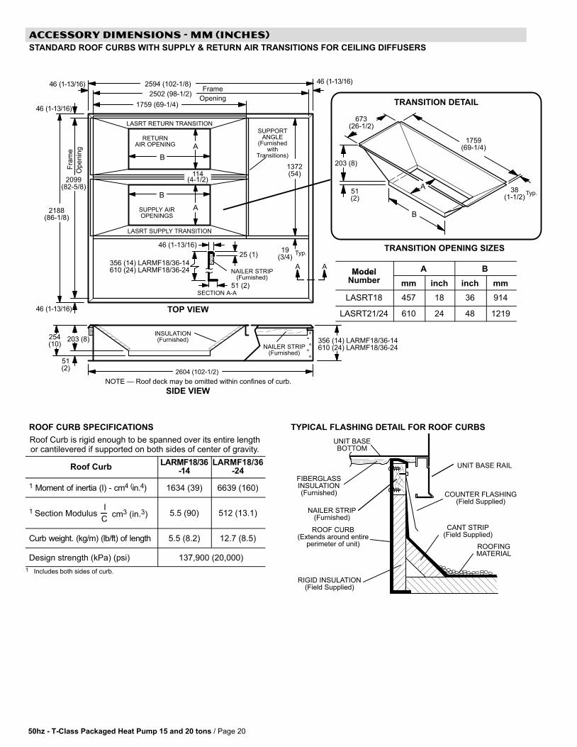
ACCESSORY DIMENSIONS − MM (INCHES)
STANDARD ROOF CURBS WITH SUPPLY & RETURN AIR TRANSITIONS FOR CEILING DIFFUSERS
Model A BModelNumber mm inch inch mm
LASRT18 457 18 36 914
LASRT21/24 610 24 48 1219
ROOF CURB SPECIFICATIONS
Roof Curb is rigid enough to be spanned over its entire lengthor cantilevered if supported on both sides of center of gravity.
Roof CurbLARMF18/36
-14LARMF18/36
-24
1 Moment of inertia (I) − cm4 (in.4) 1634 (39) 6639 (160)
1 Section Modulus cm3 (in.3)I
C5.5 (90) 512 (13.1)
Curb weight. (kg/m) (lb/ft) of length 5.5 (8.2) 12.7 (8.5)
Design strength (kPa) (psi) 137,900 (20,000)
1 Includes both sides of curb.
TYPICAL FLASHING DETAIL FOR ROOF CURBS
ROOF CURB(Extends around entire
perimeter of unit)
FIBERGLASSINSULATION(Furnished) COUNTER FLASHING
(Field Supplied)
UNIT BASEBOTTOM
RIGID INSULATION(Field Supplied)
ROOFINGMATERIAL
CANT STRIP(Field Supplied)
NAILER STRIP(Furnished)
UNIT BASE RAIL
50hz − T−Class Packaged Heat Pump 15 and 20 tons / Page 21
ACCESSORY DIMENSIONS − MM (INCHES)
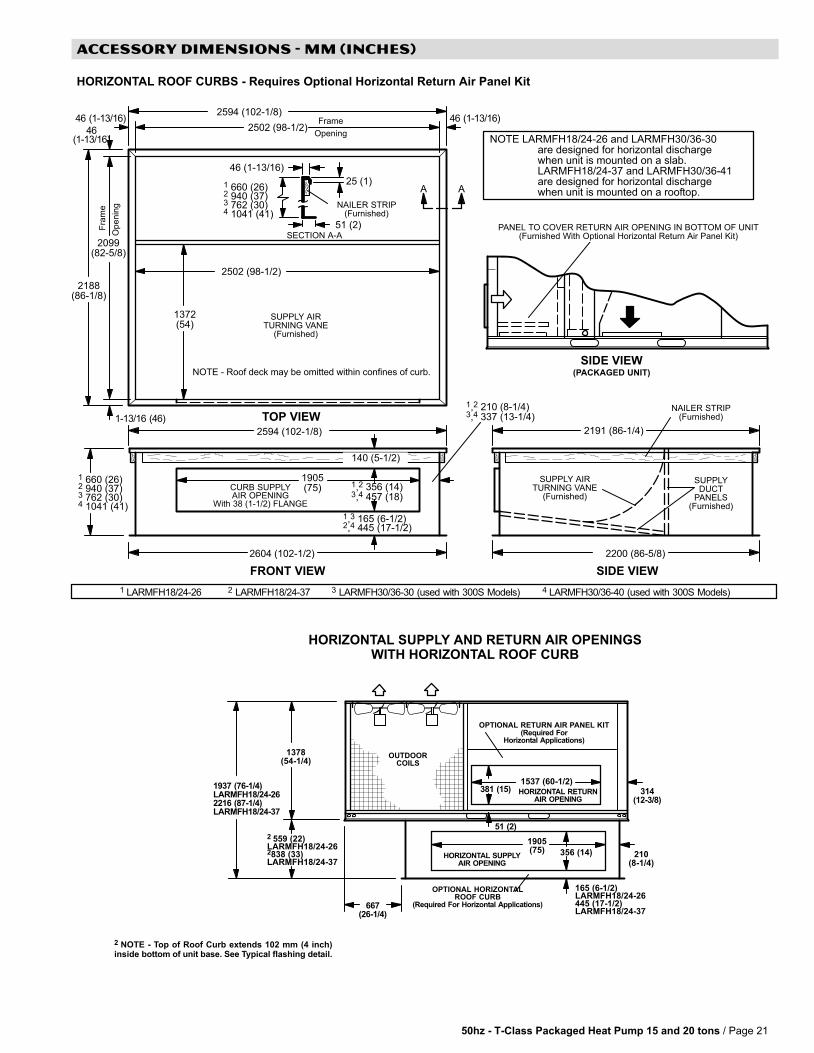
HORIZONTAL ROOF CURBS − Requires Optional Horizontal Return Air Panel Kit
1 LARMFH18/24-26 2 LARMFH18/24-37 3 LARMFH30/36-30 (used with 300S Models) 4 LARMFH30/36-40 (used with 300S Models)
2594 (102-1/8)
SIDE VIEW
TOP VIEW
Fra
me
Op
en
ing
Frame
Opening
1372(54)
2502 (98-1/2)
2099(82-5/8)
2200 (86-5/8)
2502 (98-1/2)
FRONT VIEW
NAILER STRIP(Furnished)
2604 (102-1/2)
CURB SUPPLYAIR OPENING
With 38 (1-1/2) FLANGE
1905(75)
140 (5-1/2)
SUPPLYDUCT
PANELS(Furnished)
SUPPLY AIRTURNING VANE
(Furnished)
25 (1)
51 (2)SECTION A-A
46 (1-13/16)
NAILER STRIP(Furnished)
AA
2594 (102-1/8) 2191 (86-1/4)
NOTE − Roof deck may be omitted within confines of curb.
SUPPLY AIRTURNING VANE
(Furnished)
PANEL TO COVER RETURN AIR OPENING IN BOTTOM OF UNIT(Furnished With Optional Horizontal Return Air Panel Kit)
SIDE VIEW(PACKAGED UNIT)
2188(86-1/8)
1-13/16 (46)
46(1-13/16)
46 (1-13/16)46 (1-13/16)
NOTE LARMFH18/24-26 and LARMFH30/36-30are designed for horizontal dischargewhen unit is mounted on a slab.LARMFH18/24-37 and LARMFH30/36-41are designed for horizontal dischargewhen unit is mounted on a rooftop.
1,2 210 (8-1/4)3,4 337 (13-1/4)
1,3 165 (6-1/2)2,4 445 (17-1/2)
1 660 (26)2 940 (37)3 762 (30)4 1041 (41)
1,2 356 (14)3,4 457 (18)
1 660 (26)2 940 (37)3 762 (30)4 1041 (41)
HORIZONTAL SUPPLY AND RETURN AIR OPENINGSWITH HORIZONTAL ROOF CURB
HORIZONTAL SUPPLYAIR OPENING
OPTIONAL HORIZONTALROOF CURB
(Required For Horizontal Applications)
210(8-1/4)
1905(75) 356 (14)
HORIZONTAL RETURNAIR OPENING
314(12-3/8)
381 (15)1537 (60-1/2)
51 (2)
OUTDOORCOILS
1378(54-1/4)
OPTIONAL RETURN AIR PANEL KIT(Required For
Horizontal Applications)
2 NOTE − Top of Roof Curb extends 102 mm (4 inch)inside bottom of unit base. See Typical flashing detail.
165 (6-1/2)LARMFH18/24-26445 (17-1/2)LARMFH18/24-37
2 559 (22)LARMFH18/24-262838 (33)LARMFH18/24-37
1937 (76-1/4)LARMFH18/24-262216 (87-1/4)LARMFH18/24-37
667(26-1/4)

50hz − T−Class Packaged Heat Pump 15 and 20 tons / Page 22
ACCESSORY DIMENSIONS − MM (INCHES)
COMBINATION CEILING SUPPLY AND RETURN DIFFUSERS
51 (2)51 (2)
AB
C
D
F
A
B
C
D
E
STEP-DOWN CEILING DIFFUSER FLUSH CEILING DIFFUSER
GG
H
K
EE
F
G
122(4−13/16)
117 (4−5/8)
117 (4−5/8)
122(4−13/16)
Model Number RTD11−185 RTD11−275
Amm 864 1016
Ain. 34 40
Bmm 606 225
Bin. 23−7/8 28−7/8
Cmm 257 283
Cin. 10−1/8 11−1/8
Dmm 1210 1514
Din. 47−5/8 59−5/8
Emm 1159 1470
Ein. 45−5/8 57−7/8
Fmm 914 1219
Fin. 36 48
Gmm 457 610
Gin. 18 24
Hmm 1159 1464
Hin. 45−5/8 57−5/8
Kmm 1210 1521
Kin. 47−5/8 59−5/8
Model Number FD11−185 FD11−275
Amm 613 918
Ain. 30−1/8 36−1/8
Bmm 1210 1514
Bin. 47−5/8 59−5/8
Cmm 1159 1464
Cin. 45−5/8 57−5/8
Dmm 914 1219
Din. 36 48
Emm 457 610
Ein. 18 24
Fmm 1159 1464
Fin. 45−5/8 57−5/8
Gmm 1210 1521
Gin. 47−5/8 59−5/8


NOTE − Due to Lennox’ ongoing committment to quality, Specifications, Ratings and Dimensions subject to change without notice and without incurring liability.Improper installation, adjustment, alteration, service or maintenance can cause property damage or personal injury.Installation and service must be performed by a qualified installer and servicing agency. ©2005 Lennox Industries Inc.


![luk.staff.ugm.ac.id · SALINAN PUTUSAN Nomor 01/PHPU-PRES/XVII/2019 DEMI KEADILAN BERDASARKAN KETUHANAN YANG MAHA ESA MAHKAMAH KONSTITUSI REPUBLIK INDONESIA, [1.1] Yang mengadili](https://img.pdfslide.net/doc/110x75/5d24c53e88c99323498c20da/lukstaffugmacid-salinan-putusan-nomor-01phpu-presxvii2019-demi-keadilan.jpg)