Embed Size (px)
Citation preview
37Corporation
Installation Manual
5.1 ESTIMATING MATERIAL REQUIREMENTS
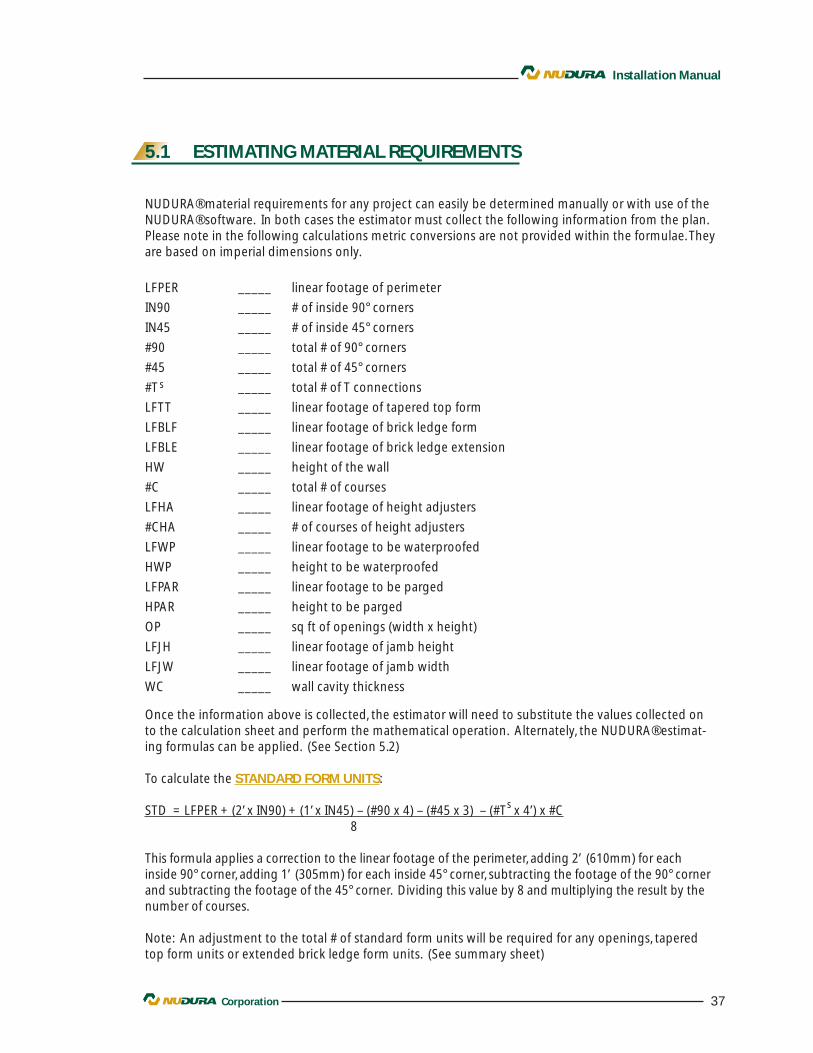
NUDURA® material requirements for any project can easily be determined manually or with use of theNUDURA® software. In both cases the estimator must collect the following information from the plan.Please note in the following calculations metric conversions are not provided within the formulae. Theyare based on imperial dimensions only.
LFPER _____ linear footage of perimeter
IN90 _____ # of inside 90° corners
IN45 _____ # of inside 45° corners
#90 _____ total # of 90° corners
#45 _____ total # of 45° corners
#T s _____ total # of T connections
LFTT _____ linear footage of tapered top form
LFBLF _____ linear footage of brick ledge form
LFBLE _____ linear footage of brick ledge extension
HW _____ height of the wall
#C _____ total # of courses
LFHA _____ linear footage of height adjusters
#CHA _____ # of courses of height adjusters
LFWP _____ linear footage to be waterproofed
HWP _____ height to be waterproofed
LFPAR _____ linear footage to be parged
HPAR _____ height to be parged
OP _____ sq ft of openings (width x height)
LFJH _____ linear footage of jamb height
LFJW _____ linear footage of jamb width
WC _____ wall cavity thickness
Once the information above is collected, the estimator will need to substitute the values collected onto the calculation sheet and perform the mathematical operation. Alternately, the NUDURA® estimat-ing formulas can be applied. (See Section 5.2)
To calculate the STANDARD FORM UNITS:
STD = LFPER + (2’ x IN90) + (1’ x IN45) – (#90 x 4) – (#45 x 3) – (#T x 4’) x #C8
This formula applies a correction to the linear footage of the perimeter, adding 2’ (610mm) for eachinside 90° corner, adding 1’ (305mm) for each inside 45° corner, subtracting the footage of the 90° cornerand subtracting the footage of the 45° corner. Dividing this value by 8 and multiplying the result by thenumber of courses.
Note: An adjustment to the total # of standard form units will be required for any openings, taperedtop form units or extended brick ledge form units. (See summary sheet)
s
38 Corporation
Installation Manual
5.1 ESTIMATING MATERIAL REQUIREMENTS CON'T.
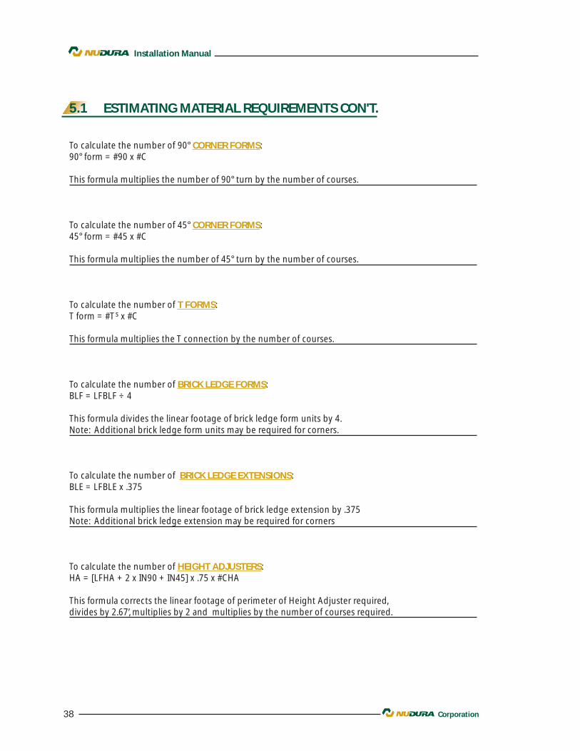
To calculate the number of 90° CORNER FORMS:90° form = #90 x #C
This formula multiplies the number of 90° turn by the number of courses.
To calculate the number of 45° CORNER FORMS:45° form = #45 x #C
This formula multiplies the number of 45° turn by the number of courses.
To calculate the number of T FORMS:T form = #T s x #C
This formula multiplies the T connection by the number of courses.
To calculate the number of BRICK LEDGE FORMS:BLF = LFBLF ÷ 4
This formula divides the linear footage of brick ledge form units by 4.Note: Additional brick ledge form units may be required for corners.
To calculate the number of BRICK LEDGE EXTENSIONS:BLE = LFBLE x .375
This formula multiplies the linear footage of brick ledge extension by .375 Note: Additional brick ledge extension may be required for corners
To calculate the number of HEIGHT ADJUSTERS:HA = [LFHA + 2 x IN90 + IN45] x .75 x #CHA
This formula corrects the linear footage of perimeter of Height Adjuster required,divides by 2.67’, multiplies by 2 and multiplies by the number of courses required.
39Corporation
Installation Manual
5.1 ESTIMATING MATERIAL REQUIREMENTS CON'T.
To calculate the number of rolls of WATERPROOFING:WP = LFWP x HWP
210
A roll of waterproofing is 225 sq. ft. (20.9m2) but the effective coverage is 210 sq. ft (19.5m2) allowingfor overlapping the edge of the membrane.
To calculate the number of bags of PREPCOAT PARGING mix:PC = LFPAR x HPAR
75
The surface area to be parged is divided by 75 which is the average coverage obtained per bag for twocoat application.
To calculate the number FIBER MESH rolls:FM = LFPAR x HPAR
475
A roll of fiber mesh is 475 sq. ft. (44.1m2) An allowance for overlap may be required depending on theapplication techniques.
To calculate the quantity of WALL ALIGNMENT SYSTEM:
WAS = LFPER + 1 per corners or tees6
The formula allows for one unit every 6’ (1.83m) plus an additional unit for every corner and tee wallconnection. Should a site have numerous openings with center of opening less than 6’ (1.83m) apart,the quantity of WAS may need to be increased.
40 Corporation
Installation Manual
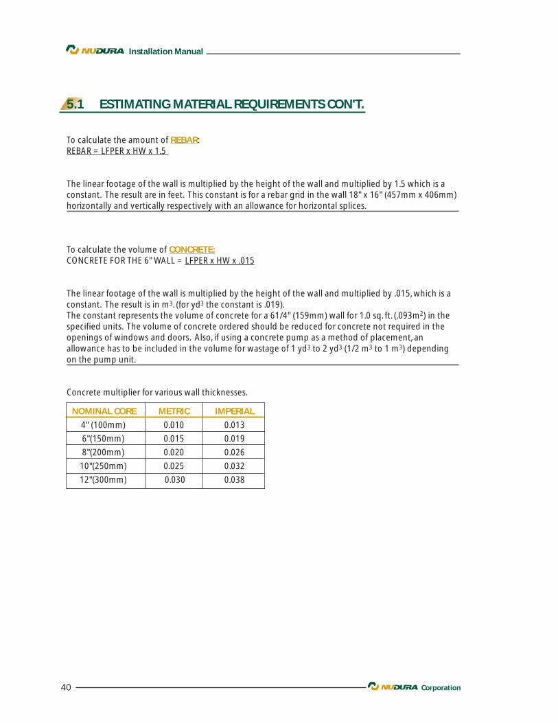
NOMINAL CORE METRIC IMPERIAL
4" (100mm) 0.010 0.013
6"(150mm) 0.015 0.019
8"(200mm) 0.020 0.026
10"(250mm) 0.025 0.032
12"(300mm) 0.030 0.038
5.1 ESTIMATING MATERIAL REQUIREMENTS CON'T.
To calculate the amount of REBAR:REBAR = LFPER x HW x 1.5
The linear footage of the wall is multiplied by the height of the wall and multiplied by 1.5 which is aconstant. The result are in feet. This constant is for a rebar grid in the wall 18" x 16" (457mm x 406mm)horizontally and vertically respectively with an allowance for horizontal splices.
To calculate the volume of CONCRETE:CONCRETE FOR THE 6" WALL = LFPER x HW x .015
The linear footage of the wall is multiplied by the height of the wall and multiplied by .015, which is aconstant. The result is in m3. (for yd3 the constant is .019).The constant represents the volume of concrete for a 61/4" (159mm) wall for 1.0 sq. ft. (.093m2) in thespecified units. The volume of concrete ordered should be reduced for concrete not required in theopenings of windows and doors. Also, if using a concrete pump as a method of placement, anallowance has to be included in the volume for wastage of 1 yd3 to 2 yd3 (1/2 m3 to 1 m3) dependingon the pump unit.
Concrete multiplier for various wall thicknesses.
41Corporation
Installation Manual
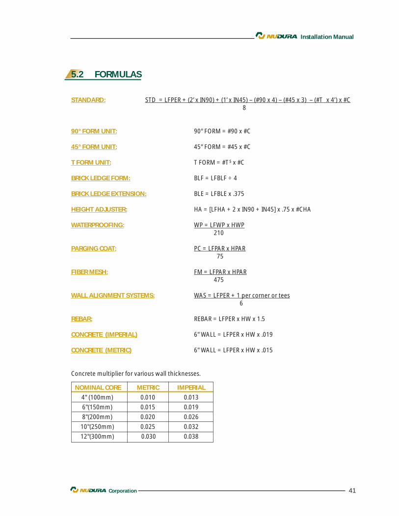
5.2 FORMULAS
STANDARD: STD = LFPER + (2’ x IN90) + (1’ x IN45) – (#90 x 4) – (#45 x 3) – (#T x 4’) x #C8
90° FORM UNIT: 90° FORM = #90 x #C
45° FORM UNIT: 45° FORM = #45 x #C
T FORM UNIT: T FORM = #T s x #C
BRICK LEDGE FORM: BLF = LFBLF ÷ 4
BRICK LEDGE EXTENSION: BLE = LFBLE x .375
HEIGHT ADJUSTER: HA = [LFHA + 2 x IN90 + IN45] x .75 x #CHA
WATERPROOFING: WP = LFWP x HWP210
PARGING COAT: PC = LFPAR x HPAR75
FIBER MESH: FM = LFPAR x HPAR475
WALL ALIGNMENT SYSTEMS: WAS = LFPER + 1 per corner or tees6
REBAR: REBAR = LFPER x HW x 1.5
CONCRETE (IMPERIAL) 6" WALL = LFPER x HW x .019
CONCRETE (METRIC) 6" WALL = LFPER x HW x .015
Concrete multiplier for various wall thicknesses.
NOMINAL CORE METRIC IMPERIAL
4" (100mm) 0.010 0.013
6"(150mm) 0.015 0.019
8"(200mm) 0.020 0.026
10"(250mm) 0.025 0.032
12"(300mm) 0.030 0.038
42 Corporation
Installation Manual
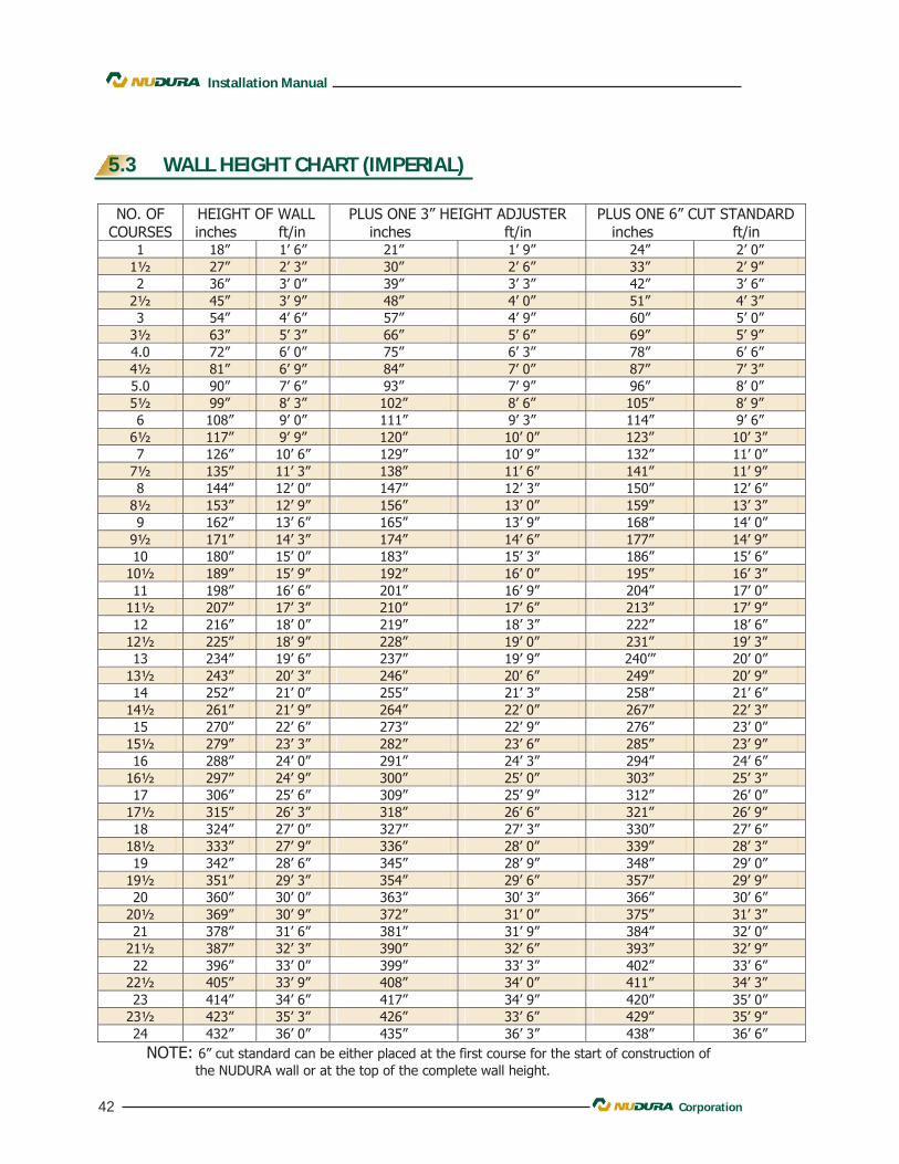
5.3 WALL HEIGHT CHART (IMPERIAL)
43Corporation
Installation Manual
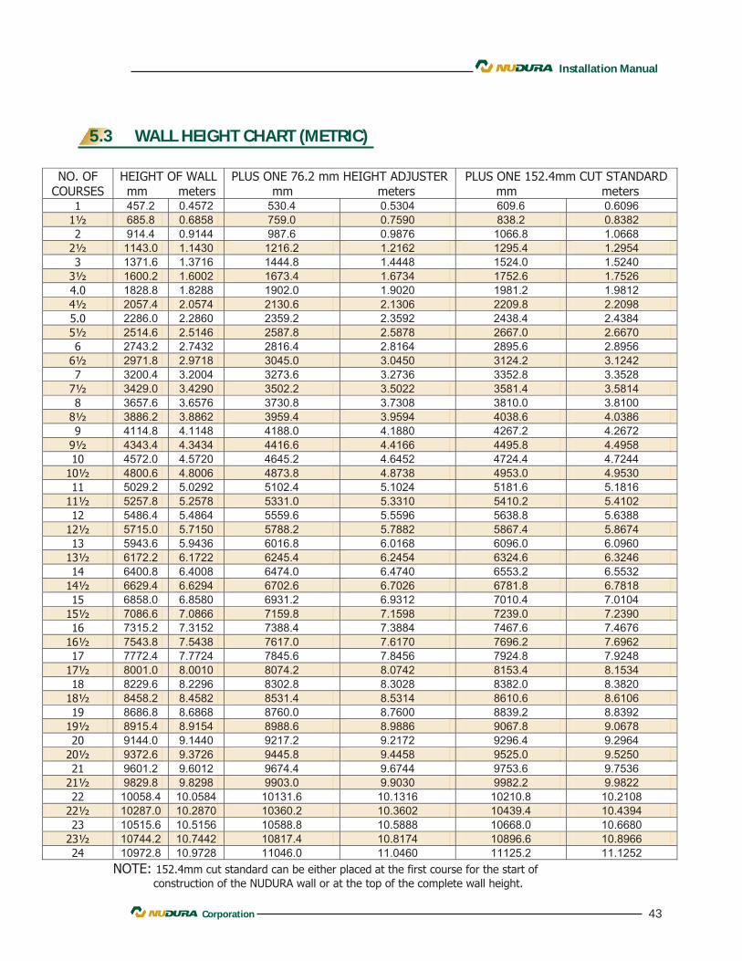
5.3 WALL HEIGHT CHART (METRIC)


![SailPoint - niap-ccevs.org · PDF file5.1 Extended Security Functional Requirements ..... 20 5.2 Extended Security Assurance Requirements ... [14] SailPoint IdentityIQ Direct Connectors](https://img.pdfslide.net/doc/110x75/5ab73a717f8b9a86428e89af/sailpoint-niap-ccevsorg-extended-security-functional-requirements-20-52.jpg)