Embed Size (px)
Citation preview
ASSEMBLY LANGUAGE PROGRAMMING (PART 1) 1
Uniform instruction format, using a single word with the opcode in the same bit positions
in every instruction, demanding less decoding;
Identical general purpose registers, allowing any register to be used in any context,
simplifying compiler design (although normally there are separate floating point
registers);
Simple addressing modes. Complex addressing performed via sequences of arithmetic
and/or load-store operations;
Few data types in hardware, some CISCs have byte string instructions, or support
complex numbers; this is so far unlikely to be found on a RISC.
RISC designs are also more likely to feature a Harvard memory model, where the instruction
stream and the data stream are conceptually separated; this means that modifying the
memory where code is held might not have any effect on the instructions executed by the
processor (because the CPU has a separate instruction and data cache), at least until a special
synchronization instruction is issued. On the upside, this allows both caches to be accessed
simultaneously, which can often improve performance.
5.2 COMPLEX INSTRUCTION SET COMPUTER
Complex Instruction Set Computers (CISC) have a large instruction set, with hardware
support for a wide variety of operations. In scientific, engineering, and mathematical operations
with hand coded assembly language (and some business applications with hand coded assembly
language), CISC processors usually perform the most work in the shortest time.
The primary goal of CISC architecture is to complete a task in as few lines of assembly as
possible. This is achieved by building processor hardware that is capable of understanding and
executing a series of operations.
RISC VS. CISC
RISC and CISC architecture can be compared by examining the example below;
ASSEMBLY LANGUAGE PROGRAMMING (PART 1) 2
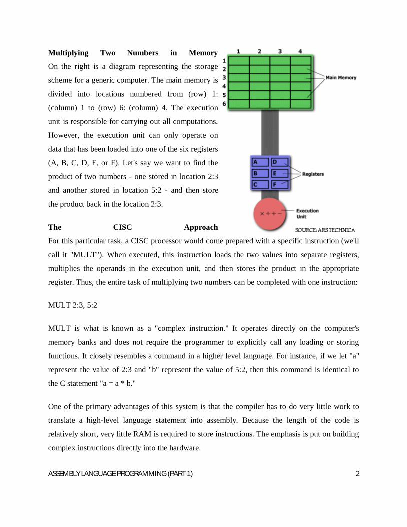
Multiplying Two Numbers in Memory
On the right is a diagram representing the storage
scheme for a generic computer. The main memory is
divided into locations numbered from (row) 1:
(column) 1 to (row) 6: (column) 4. The execution
unit is responsible for carrying out all computations.
However, the execution unit can only operate on
data that has been loaded into one of the six registers
(A, B, C, D, E, or F). Let's say we want to find the
product of two numbers - one stored in location 2:3
and another stored in location 5:2 - and then store
the product back in the location 2:3.
The CISC Approach
For this particular task, a CISC processor would come prepared with a specific instruction (we'll
call it "MULT"). When executed, this instruction loads the two values into separate registers,
multiplies the operands in the execution unit, and then stores the product in the appropriate
register. Thus, the entire task of multiplying two numbers can be completed with one instruction:
MULT 2:3, 5:2
MULT is what is known as a "complex instruction." It operates directly on the computer's
memory banks and does not require the programmer to explicitly call any loading or storing
functions. It closely resembles a command in a higher level language. For instance, if we let "a"
represent the value of 2:3 and "b" represent the value of 5:2, then this command is identical to
the C statement "a = a * b."
One of the primary advantages of this system is that the compiler has to do very little work to
translate a high-level language statement into assembly. Because the length of the code is
relatively short, very little RAM is required to store instructions. The emphasis is put on building
complex instructions directly into the hardware.
ASSEMBLY LANGUAGE PROGRAMMING (PART 1) 3
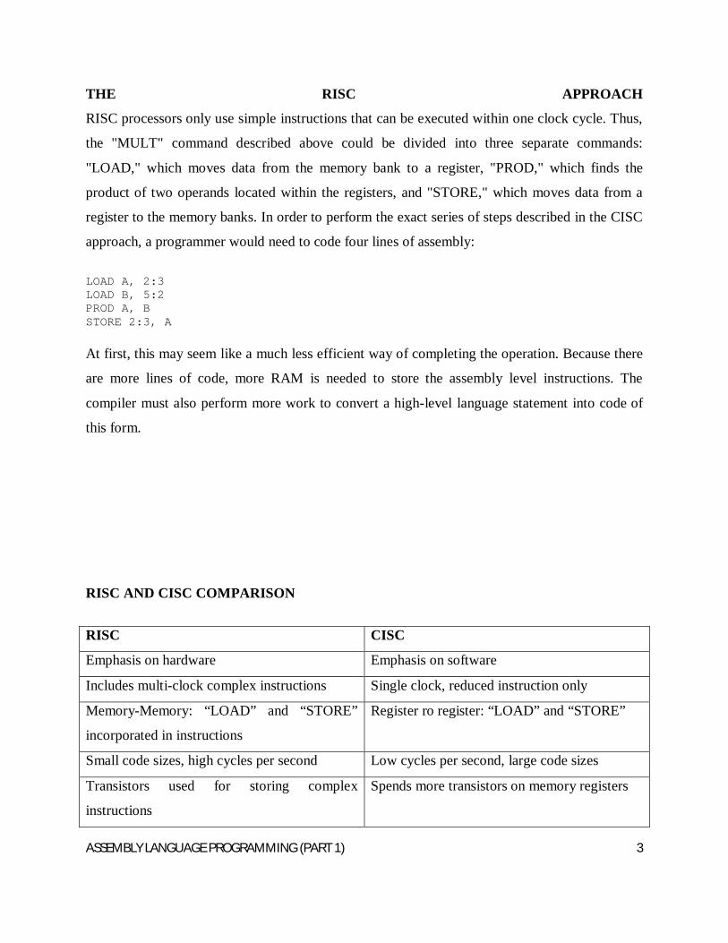
THE RISC APPROACH
RISC processors only use simple instructions that can be executed within one clock cycle. Thus,
the "MULT" command described above could be divided into three separate commands:
"LOAD," which moves data from the memory bank to a register, "PROD," which finds the
product of two operands located within the registers, and "STORE," which moves data from a
register to the memory banks. In order to perform the exact series of steps described in the CISC
approach, a programmer would need to code four lines of assembly:
LOAD A, 2:3 LOAD B, 5:2 PROD A, B STORE 2:3, A
At first, this may seem like a much less efficient way of completing the operation. Because there
are more lines of code, more RAM is needed to store the assembly level instructions. The
compiler must also perform more work to convert a high-level language statement into code of
this form.
RISC AND CISC COMPARISON
RISC CISC
Emphasis on hardware Emphasis on software
Includes multi-clock complex instructions Single clock, reduced instruction only
Memory-Memory: “LOAD” and “STORE”
incorporated in instructions
Register ro register: “LOAD” and “STORE”
Small code sizes, high cycles per second Low cycles per second, large code sizes
Transistors used for storing complex
instructions
Spends more transistors on memory registers
ASSEMBLY LANGUAGE PROGRAMMING (PART 1) 4
Separating the "LOAD" and "STORE" instructions actually reduces the amount of work that the
computer must perform. After a CISC-style "MULT" command is executed, the processor
automatically erases the registers. If one of the operands needs to be used for another
computation, the processor must re-load the data from the memory bank into a register. In RISC,
the operand will remain in the register until another value is loaded in its place.
The CISC approach attempts to minimize the number of instructions per program, sacrificing the
number of cycles per instruction. RISC does the opposite, reducing the cycles per instruction at
the cost of the number of instructions per program
SECTION TWO
CHAPTER SIX
REGISTERS
Registers are used for storing variables. Because registers are located inside the CPU, they are
much faster than memory. Accessing a memory location requires the use of a system bus, so it
takes longer time. Accessing data in a register usually takes no time. Therefore, variables should
be often kept in registers. From the assembly language point of view, this chapter discusses the
ASSEMBLY LANGUAGE PROGRAMMING (PART 1) 5
80x86 register sets. The 80x86 processors provide a set of general purpose registers, segment
registers and some special purpose registers. Certain members of the family provide additional
registers, although typical applications do not use them. Register sets are very small and most
registers have special purpose which limits their use as variables, but they are still an excellent
place to store temporary data of calculations.
6.1 GENERAL PURPOSE REGISTERS
8086 CPU has eight 16 bit general purpose registers; each register has its own name:
AX- the accumulator register (divided into AH/AL)
BX- the base register (divided into BH/BL)
CX-the count register (divided into CH/CL)
DX- the data register (divided into DH/DL)
SI- source index register
DI- destination index register
BP- base pointer
SP- stack pointer
Despite the name of a register, it’s the programmer who determines the usage for each general
purpose register. The size of the above general purpose registers are 16bit, it’s something like:
0011000000111001b
Four general purpose registers (AX, BX, CX, and DX) are made of two separate 8 bit registers,
e.g
If AX=0011000000111001b, then AH=00110000b and AL=00111001b. Therefore, when any of
the 8 bit registers are modified, 16 bit register is also updated and vice versa. The same thing also
applies for the other 3 registers (BX, CX and DX). “H” stands for high and “L” stands for low
part.
ASSEMBLY LANGUAGE PROGRAMMING (PART 1) 6
While you can use many of these registers interchangeably in a computation, many instructions
work more efficiently or absolutely require a specific register from this general purpose register
group.
A brief explanation of the general purpose registers is given below;
The ax register: This is also called the accumulator. It is where most arithmetic and logical
computations take place. Although, most arithmetic and logical operations can be done in other
registers, it is often more efficient to use the ax register for such computations
The bx register: This is the base register. It has some special purpose too. It is commonly used
to hold indirect addresses.
The cx register: This is the count register. As the name implies, it is used to count off the
number of iterations in a loop or to specify the number of characters in a string.
The dx register: This is the data register. This register has two special purposes: It holds the
overflow from certain arithmetic operations and it holds I/O addresses when accessing data on
the 80x86 I/O bus.
The si and di register are respectively the source index and the destination index register. These
registers can be used to indirectly access memory. These registers are also used with the 8086
string instructions when processing character strings.
The bp register: This is the base pointer. It is similar to bx register. It is used to access
parameters and local variables in a procedure.
The sp register: This is the stack pointer. It has a very special purpose of maintaining the
program stack.
6.2 SEGMENT REGISTERS
ASSEMBLY LANGUAGE PROGRAMMING (PART 1) 7
8086 CPU has four 16 bit general purpose registers; each register has its own name:
cs register stands for the code segment register
ds register stands for the data segment register
es register stands for the extra segment register
ss register stands foe the stack segment register
Segment registers points at the beginning of a segment in memory. Segments of memory on the
8086 can be no larger than 65,536 bytes long (64K). A brief explanation of the segment registers
is given below;
The cs register points at the segment containing the currently executing machine instructions.
Despite the 64K segment limitation, 8086 programs can be longer than 64K. This can be possible
if multiple code segments are in memory.
The ds register generally points at global variables for the program. Again, one is limited to
65,536 bytes of data in the data segment but the value of ds can always be changed in order to
access additional data in other segments.
The es register are often used by programs to gain access to segments when it is difficult or
impossible to modify the other segment registers.
The ss register points at the segment containing the 8086 stack. The stack is where the 8086
stores important machine state information, subroutine return addresses, procedure parameters
and local variables. In general, the stack segment is not always modified because too many
things in the system depend upon it. Although, it is theoretically possible to store data in the
segment registers, this is not a good idea.
The segment registers have a very special purpose- pointing at accessible blocks of memory.
Any attempt to use the registers for any other purpose may result in considerable grief, especially
if intended to move up to better CPU like 80386. Segment registers work together with general
purpose register to access any memory value.
ASSEMBLY LANGUAGE PROGRAMMING (PART 1) 8
e.g If we would like to access memory at the physical address 12345h(hexadecimal), we should
set the DS=1230h and SI=0045h. This is good, since this way we can access much more
information than with a single register that is limited to 16 bit.
CPU make a calculation of physical address by multiplying the segment register by 10h and
adding a general purpose register to it (1230h * 10h + 45h = 12345h)
The address formed with two registers is called an effective address. By default BX, SI and DI
registers work with DS segment register; BP and SP work with SS segment register. Other
general purpose registers cannot form an effective address. Also, although BX can form an
effective address, BH and BL cannot.
10.2 SPECIAL PURPOSE REGISTERS
There are two types of special purpose registers on the 8086 CPU: the instruction pointer (ip) and
the flags register. These registers are not accessed the same way other 8086 registers are
accessed. Instead, the CPU generally manipulates these registers directly. A brief explanation of
the special purpose registers is given below;
The ip register contains the address of the currently executing instruction. It is a 16 bit pointer
which provides a pointer into the current code segment. IP works together with the CS segment
register and it points to the currently executing instruction.
The flags register is unlike the other registers on the 8086. The other registers hold eight or 16
bit values. The flags register is simply an eclectic collection of on e bit values which help
determine the current state of the processor. Flags register is modified automatically by CPU
after mathematical operations, this allows to determine the type of the result and to determine the
conditions to transfer control to other parts of the program. Generally, the flags register cannot
be accessed directly. Although the flags register is 16 bits wide, the 8086 uses only nine of those
bits. These bits are explained below;
The carry bits (C): It holds the carry after addition or after subtraction (or the borrow after
subtraction). It also indicates an error condition.
ASSEMBLY LANGUAGE PROGRAMMING (PART 1) 9
The parity bits: it is a count of one in a number expressed as even or odd. It is used as error
detection in some circuits.
The Auxiliary carry bit (A): This holds the half-carry after addition or the borrow after
subtraction between bit positions 3 and 4 of the results. It is set by a carry out of the lowest
nibble (1/2 byte) or a borrow into the lowest nibble.
The zero flag bit (Z): It is set when the result of the operation is zero.
The sign bit (S): This flag holds the arithmetic sign of the result after arithmetic or logic
instruction is executed.
The trap flag (T): If the T flag is enabled, the microprocessor interrupts the flow of the program
on conditions as indicated by the debug registers and control register. If T=0, the debugging
feature is disabled.
The Interrupt flag bit (I): This flag determines whether an external interrupt are disabled or
not.
The Direction flag bit (D): This flag determines the direction which string operations are
performed. When cleared, string operations proceed from left to right or vice versa.
The overflow flag bit (O): Overflow occurs when signed numbers are added or subtracted. An
overflow indicates that the result has exceeded the capacity of the machine.
Of all these flags, four flags are used most times and they are; zero, carry, sign and
CHAPTER SEVEN
ADDRESSING MODES
One approach to processors places an emphasis on flexibility of addressing modes. Some
engineers and programmers believe that the real power of a processor lies in its addressing
modes. Most addressing modes can be created by combining two or more basic addressing
ASSEMBLY LANGUAGE PROGRAMMING (PART 1) 10
modes, although building the combination in software will usually take more time than if the
combination addressing mode existed in hardware (although there is a trade-off that slows down
all operations to allow for more complexity). The x86 instructions use five different operand
types: registers, constants, and three memories addressing schemes. Each form is called an
addressing mode. The x86 processors support the register addressing mode, the immediate
addressing mode, the indirect addressing mode, the indexed addressing mode and the direct
addressing mode.
One approach to processors places an emphasis on flexibility of addressing modes. Some
engineers and programmers believe that the real power of a processor lies in its addressing
modes. Most addressing modes can be created by combining two or more basic addressing
modes, although building the combination in software will usually take more time than if the
combination addressing mode existed in hardware (although there is a trade-off that slows down
all operations to allow for more complexity).
In a purely othogonal instruction set, every addressing mode would be available for every
instruction. In practice, this isn’t the case.
Virtual memory, memory pages, and other hardware mapping methods may be layered on top
of the addressing modes.
7.1 ADDRESSING MODES WITH REGISTER OPERANDS
Register operands are the easiest to understand. Consider the following forms of the mov
instruction:
mov ax,ax
mov ax,bx
mov ax,cx
mov ax, dx
ASSEMBLY LANGUAGE PROGRAMMING (PART 1) 11
In the above instructions, the first instruction is the destination register and the second operand is
the source register. The first instruction does nothing. It copies the value from the ax register
back into the ax register. The remaining three instructions copy the value of bx,cx, and dx into
ax. Note that the original values of bx, cx and dx remain the same. The first operand (the
destination register) is not limited to ax; you can move values to any of these registers. This
mode of addressing is the register addressing mode
7.2 ADDRESSING MODES WITH CONSTANTS
Constants are also pretty easy to deal with. Consider the following instructions:
mov ax,25
mov bx, 195
mov cx,2056
mov dx,1000
These instructions are all pretty straightforward; they load their respective registers with the
specified hexadecimal constant. This mode of addressing is called the immediate addressing
mode.
7.3 ADDRESSING MODES WITH MEMORY STRUCTURES
There are three addressing modes which deal with accessing data in memory. There are three
main addressing mode found in this category; the direct addressing mode, the indirect
addressing mode and the index addressing mode. These addressing modes take the following
forms:
mov ax, [1000]
mov ax, [bx]
mov ax, [1000+bx]
ASSEMBLY LANGUAGE PROGRAMMING (PART 1) 12
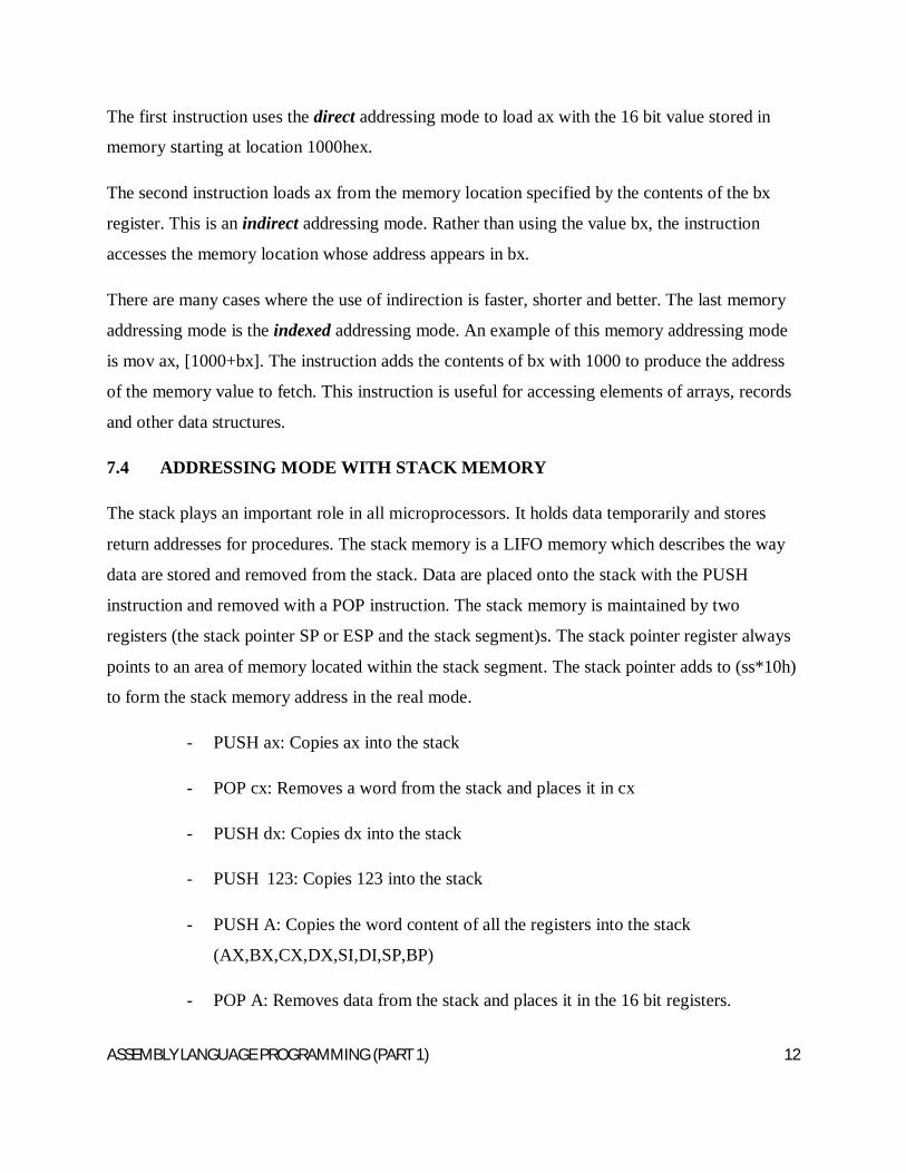
The first instruction uses the direct addressing mode to load ax with the 16 bit value stored in
memory starting at location 1000hex.
The second instruction loads ax from the memory location specified by the contents of the bx
register. This is an indirect addressing mode. Rather than using the value bx, the instruction
accesses the memory location whose address appears in bx.
There are many cases where the use of indirection is faster, shorter and better. The last memory
addressing mode is the indexed addressing mode. An example of this memory addressing mode
is mov ax, [1000+bx]. The instruction adds the contents of bx with 1000 to produce the address
of the memory value to fetch. This instruction is useful for accessing elements of arrays, records
and other data structures.
7.4 ADDRESSING MODE WITH STACK MEMORY
The stack plays an important role in all microprocessors. It holds data temporarily and stores
return addresses for procedures. The stack memory is a LIFO memory which describes the way
data are stored and removed from the stack. Data are placed onto the stack with the PUSH
instruction and removed with a POP instruction. The stack memory is maintained by two
registers (the stack pointer SP or ESP and the stack segment)s. The stack pointer register always
points to an area of memory located within the stack segment. The stack pointer adds to (ss*10h)
to form the stack memory address in the real mode.
- PUSH ax: Copies ax into the stack
- POP cx: Removes a word from the stack and places it in cx
- PUSH dx: Copies dx into the stack
- PUSH 123: Copies 123 into the stack
- PUSH A: Copies the word content of all the registers into the stack
(AX,BX,CX,DX,SI,DI,SP,BP)
- POP A: Removes data from the stack and places it in the 16 bit registers.
ASSEMBLY LANGUAGE PROGRAMMING (PART 1) 13
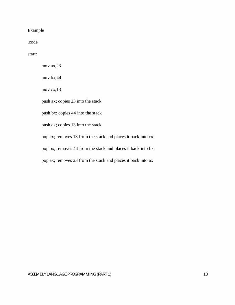
Example
.code
start:
mov ax,23
mov bx,44
mov cx,13
push ax; copies 23 into the stack
push bx; copies 44 into the stack
push cx; copies 13 into the stack
pop cx; removes 13 from the stack and places it back into cx
pop bx; removes 44 from the stack and places it back into bx
pop ax; removes 23 from the stack and places it back into ax
ASSEMBLY LANGUAGE PROGRAMMING (PART 1) 14
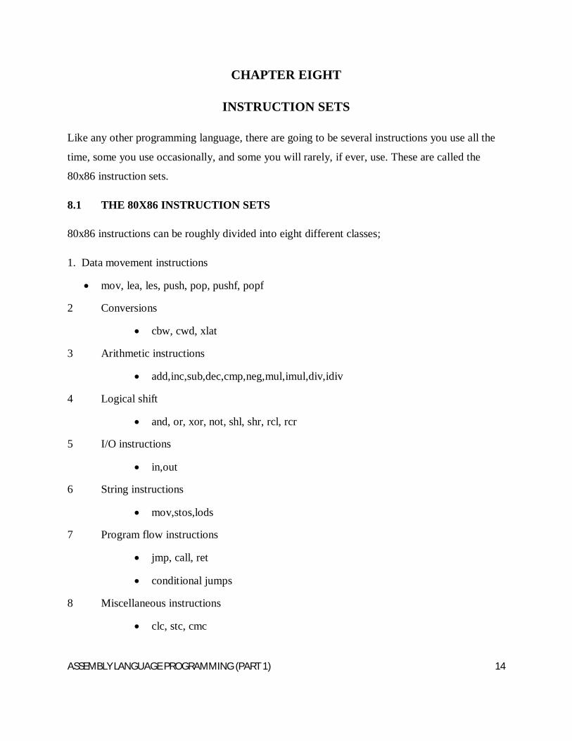
CHAPTER EIGHT
INSTRUCTION SETS
Like any other programming language, there are going to be several instructions you use all the
time, some you use occasionally, and some you will rarely, if ever, use. These are called the
80x86 instruction sets.
8.1 THE 80X86 INSTRUCTION SETS
80x86 instructions can be roughly divided into eight different classes;
1. Data movement instructions
mov, lea, les, push, pop, pushf, popf
2 Conversions
cbw, cwd, xlat
3 Arithmetic instructions
add,inc,sub,dec,cmp,neg,mul,imul,div,idiv
4 Logical shift
and, or, xor, not, shl, shr, rcl, rcr
5 I/O instructions
in,out
6 String instructions
mov,stos,lods
7 Program flow instructions
jmp, call, ret
conditional jumps
8 Miscellaneous instructions
clc, stc, cmc
ASSEMBLY LANGUAGE PROGRAMMING (PART 1) 15
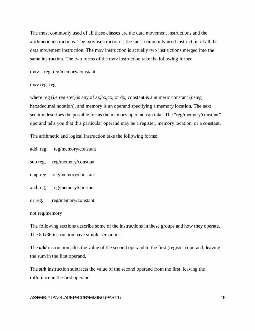
The most commonly used of all these classes are the data movement instructions and the
arithmetic instructions. The mov isnstruction is the most commonly used instruction of all the
data movement instruction. The mov instruction is actually two instructions merged into the
same instruction. The two forms of the mov instruction take the following forms;
mov reg, reg/memory/constant
mov reg, reg
where reg (i.e register) is any of ax,bx,cx, or dx; constant is a numeric constant (using
hexadecimal notation), and memory is an operand specifying a memory location. The next
section describes the possible forms the memory operand can take. The “reg/memory/constant”
operand tells you that this particular operand may be a register, memory location, or a constant.
The arithmetic and logical instruction take the following forms:
add reg, reg/memory/constant
sub reg, reg/memory/constant
cmp reg, reg/memory/constant
and reg, reg/memory/constant
or reg, reg/memory/constant
not reg/memory
The following sections describe some of the instructions in these groups and how they operate.
The 80x86 instruction have simple semantics.
The add instruction adds the value of the second operand to the first (register) operand, leaving
the sum in the first operand.
The sub instruction subtracts the value of the second operand from the first, leaving the
difference in the first operand.
ASSEMBLY LANGUAGE PROGRAMMING (PART 1) 16
The cmp instruction subtracts the value of the second operand from the first, leaving the
difference in the first operand.
The and & or instructions compute the corresponding bitwise logical operation on the two
operands and store the result in the first operand.
The not instruction invert the bit in the single memory or register operand.
8.2 CONTROL TRANSFER INSTRUCTION
The control transfer instructions interrupt the sequential execution of instructions in memory and
transfer control to some other point in memory either unconditionally, or system organization
after testing the result of thr previous cmp instruction. These instructions include the following;
ja dest--jump if above
jae dest--jump if above or equal
jb dest--jump if below
jbe dest--jump if below or equal
je dest—jump if equal
jne dest—jum if not equal
jmp dest-unconditional jump
iret return from an interrupt
The first six instructionsnin this class let you check the result of the previous cmp instruction for
greater than, greater or equal, less than or equal,equality, or inequality. For example, if you
compare the ax and bx registers with the cmp instruction and execute the ja instruction, the x86
CPU will jump to the specified destination location if ax was greater than bx. If ax is not greater
than bx, control will fall through to the next instruction in the program. The jmp instruction
unconditionally transfers control to the instruction at the destination address. The iret instruction
returns control from an interrup service routine.The get and put instructions let you read and
ASSEMBLY LANGUAGE PROGRAMMING (PART 1) 17
write integer values. Get will stop and prompt the user for a hexadecimal value and then store
that value into the ax register. Put displays (in hexadecimal) the value of the ax register. The
remaining instructions do not require any operands, they are halt and brk. Halt terminates
program execution and brk stops the program in a state that it can be restarted.
8.3 THE STANDARD INPUT ROUTINES
While the standard library provides several input routines, there are three in particular that will
be used be used most times.
- Getc (gets a character)
- Gets(gets a string)
- Getsm
Getc reads a single character from the keyboard and returns that character in a register. It does
not modiffy any other registers. As usual, the carry flag returns the error status. You do not need
to pass getc any values in th rgisters. Getc does not echo the input character to the display screen.
You must explicitly print the character if you want it to appear on the output monitor.
The gets routine reads an entire line of text from the keyboard. It stores each successive character
of the input line into a byte array whose base address in the es:di register pair. This array must
have a room of 128bytes. The gets routine will read each character and place it in the array
except for the carriage return character. Gets terminates the input line with a zero byte. Gets
echoes each character you type to the display device, it also handles simple line editing functions
such as backspace.
The getsm routine reads a string from the keyboard and returns a pointer to that string in nes:di
pair register. The difference between gets an getsm is that you do not have to pass the address of
an input buffer in es:di. Getsm automatically allocates storage on the heap with a call to malloc
and returns a pointer to the buffer in es:di.
ASSEMBLY LANGUAGE PROGRAMMING (PART 1) 18
8.4 THE STANDARD OUTPUT ROUTINES
The basic standard output routines are; PUTC, PUTCR, PUTS, PUTH, PUTI, PRINT and
PRINTF
Putc outputs a single character to the display device. It outputs the character appearing in the al
register. It does not affect any registers unless there is an error on output ( the carry flag denotes
error/no error).
Putcr outputs a “newline” to the standard output.
Puts (put a string) routine prints the zero terminated string at which es:di points. Puts does not
automatically output a new line after printing the string.
The puth routine prints the value in the al register as exactly two hexadecimal digits including a
leading zero byte if the value is in the range (0..Fh).
The puti routine puts the value in the ax as a signed 16 bit integer
The print routine is one of the most often called procedures in the library. It prints the zero
terminated string that immediately follows the call to the string.
Printf uses the escape character (“\”) to print special characters in the fashion similar to, but not
identical to C’s printf.
8.5 MACROS
Many assemblers support macros, programmer-defined symbols that stand for some sequence of
text lines. This sequence of text lines may include a sequence of instructions, or a sequence of
data storage pseudo-ops. Once a macro has been defined using the appropriate pseudo-op, its
name may be used in place of a mnemonic. When the assembler processes such a statement, it
replaces the statement with the text lines associated with that macro, then processes them just as
though they had appeared in the source code file all along (including, in better assemblers,
expansion of any macros appearing in the replacement text).
ASSEMBLY LANGUAGE PROGRAMMING (PART 1) 19
Since macros can have 'short' names but expand to several or indeed many lines of code, they
can be used to make assembly language programs appear to be much shorter (require less lines of
source code from the application programmer - as with a higher level language). They can also
be used to add higher levels of structure to assembly programs, optionally introduce embedded
de-bugging code via parameters and other similar features.
Many assemblers have built-in macros for system calls and other special code sequences.
Macro assemblers often allow macros to take parameters. Some assemblers include quite
sophisticated macro languages, incorporating such high-level language elements as optional
parameters, symbolic variables, conditionals, string manipulation, and arithmetic operations, all
usable during the execution of a given macros, and allowing macros to save context or exchange
information. Thus a macro might generate a large number of assembly language instructions or
data definitions, based on the macro arguments. This could be used to generate record-style data
structures or "unrolled" loops, for example, or could generate entire algorithms based on
complex parameters. An organization using assembly language that has been heavily extended
using such a macro suite can be considered to be working in a higher-level language, since such
programmers are not working with a computer's lowest-level conceptual elements.
ASSEMBLY LANGUAGE PROGRAMMING (PART 1) 20
CHAPTER NINE
ASSEMBLY LANGUAGE PROGRAM
A program written in assembly language consists of a series of instructions--mnemonics that
correspond to a stream of executable instructions, when translated by an assembler, that can be
loaded into memory and executed.
For example, an x86/IA-32 processor can execute the following binary instruction as expressed
in machine language (see x86 assembly language):
Binary: 10110000 01100001 (Hexadecimal: B0 61)
The equivalent assembly language representation is easier to remember (example in Intel syntax,
more mnemonic):
MOV AL, #61h
This instruction means:
Move the value 61h (or 97 decimal; the h-suffix means hexadecimal; the pound sign
means move the immediate value, not location) into the processor register named "AL".
The mnemonic "mov" represents the opcode 1011 which moves the value in the second operand
into the register indicated by the first operand. The mnemonic was chosen by the instruction set
designer to abbreviate "move", making it easier for the programmer to remember. A comma-
separated list of arguments or parameters follows the opcode; this is a typical assembly language
statement.
9.1 OVERVIEW OF ASSEMBLY LANGUAGE PROGRAMMING
In practice many programmers drop the word mnemonic and, technically incorrectly, call "mov"
an opcode. When they do this they are referring to the underlying binary code which it
represents. To put it another way, a mnemonic such as "mov" is not an opcode, but as it
ASSEMBLY LANGUAGE PROGRAMMING (PART 1) 21
symbolizes an opcode, one might refer to "the opcode mov" for example when one intends to
refer to the binary opcode it symbolizes rather than to the symbol--the mnemonic--itself. As few
modern programmers have need to be mindful of actually what binary patterns are the opcodes
for specific instructions, the distinction has in practice become a bit blurred among programmers
but not among processor designers.
Transforming assembly into machine language is accomplished by an assembler, and the reverse
by a disassembler. Unlike in high-level languages, there is usually a one-to-one correspondence
between simple assembly statements and machine language instructions. However, in some
cases, an assembler may provide pseudoinstructions which expand into several machine
language instructions to provide commonly needed functionality. For example, for a machine
that lacks a "branch if greater or equal" instruction, an assembler may provide a
pseudoinstruction that expands to the machine's "set if less than" and "branch if zero (on the
result of the set instruction)". Most full-featured assemblers also provide a rich macro language
(discussed below) which is used by vendors and programmers to generate more complex code
and data sequences.
Each computer architecture and processor architecture has its own machine language. On this
level, each instruction is simple enough to be executed using a relatively small number of
electronic circuits. Computers differ by the number and type of operations they support. For
example, a new 64-bit machine would have different circuitry from a 32-bit machine. They may
also have different sizes and numbers of registers, and different representations of data types in
storage. While most general-purpose computers are able to carry out essentially the same
functionality, the ways they do so differ; the corresponding assembly languages reflect these
differences.
9.2 THE LINKER
The Linker is used for linking the output of an assembler to an executable file.
Basically a linker is used for large projects where there is more than one file to be assembled.
Each of the assembly language files might contain references to code elements in the other files.
ASSEMBLY LANGUAGE PROGRAMMING (PART 1) 22
A linker is the program that ties all the loose ends together and makes a single program out of the
pieces.
Thus, technically, an assembler converts assembly language files to object files (basically
machine code with some loose ends), and a linker connects all the object files together and
makes a single executable program out of them.
However, there are some assemblers that do not require the use of a linker. E.g Flat Assembler
FASM.
Actually, a linker is not just specific to assembly language programing. It is used fairly much
regardless of the language in which you are programming.
An example of a linker is the ALINK
9.3 COMMON ASSEMBLERS
Some commonly used assemblers are listed below;
Lazy Assembler (LZASM)
GoASM
Flat Assembler (FASM)
MASM32
Pass32
Netwide Assembler (NASM)
In this course, the Microsoft Micro Assembler (MASM) will be used.
ASSEMBLY LANGUAGE PROGRAMMING (PART 1) 23
9.4 A SIMPLE HELLO WORLD PROGRAM USING FLAT ASSEMBLER(FASM)
Include ‘%fasminc%/win32ax.inc’
.code
start:
invoke MessageBox, HWND_DESKTOP, ”Hello World! “, “Win32 Assembly”,MB_OK
invoke ExitProcess, 0
.endstart
The first line includes a special macro file win32ax.inc
The next line tells the assembler we are going to include some code now.
The line start: is simply a label. It just gives a name to one of the lines of our program so we can
refer to it elsewhere. We'll use labels often, for example when writing loops or using other jump
instructions. The label will simply allow us to refer to that particular location within our code, by
name; say for example if we wanted to jump to that location from somewhere else.
The program is ended with the .end directive. It takes one parameter, the name of a label
corresponding to the entry point of the program (which doesn't need to be at the start of the
program). When the program is loaded into memory by the operating system, execution of the
program will begin at this point.
9.5 A SIMPLE HELLO WORLD PROGRAM USING NETWIDE ASSEMBLY LANGUAGE (NASM)
1: %include 'system.inc' 2: 3: section .data
ASSEMBLY LANGUAGE PROGRAMMING (PART 1) 24
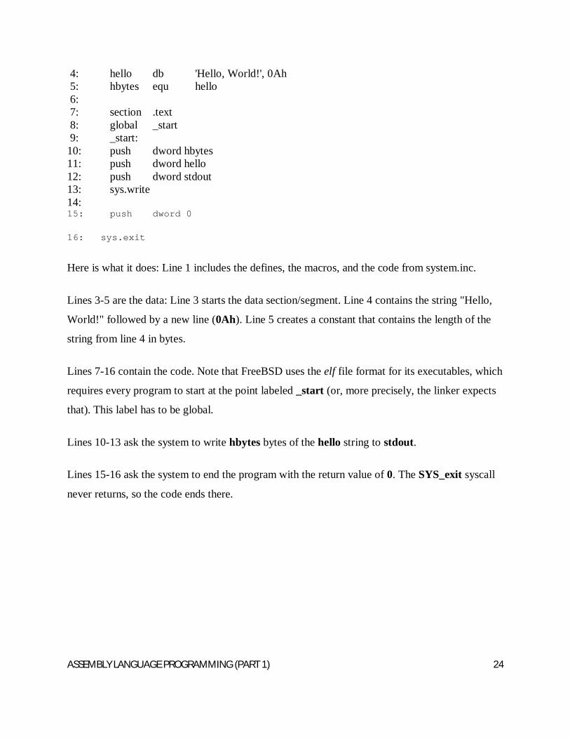
4: hello db 'Hello, World!', 0Ah 5: hbytes equ hello 6: 7: section .text 8: global _start 9: _start: 10: push dword hbytes 11: push dword hello 12: push dword stdout 13: sys.write 14: 15: push dword 0
16: sys.exit
Here is what it does: Line 1 includes the defines, the macros, and the code from system.inc.
Lines 3-5 are the data: Line 3 starts the data section/segment. Line 4 contains the string "Hello,
World!" followed by a new line (0Ah). Line 5 creates a constant that contains the length of the
string from line 4 in bytes.
Lines 7-16 contain the code. Note that FreeBSD uses the elf file format for its executables, which
requires every program to start at the point labeled _start (or, more precisely, the linker expects
that). This label has to be global.
Lines 10-13 ask the system to write hbytes bytes of the hello string to stdout.
Lines 15-16 ask the system to end the program with the return value of 0. The SYS_exit syscall
never returns, so the code ends there.
ASSEMBLY LANGUAGE PROGRAMMING (PART 1) 25
CHAPTER TEN
JOB CONTROL LANGUAGE
10.1 INTRODUCTION
Job Control Language (JCL) is a scripting language used on IBM mainframe operating
systems to instruct the system on how to run a batch job or start a subsystem. The term "Job
Control Language" can also be used generically to refer to all languages which perform these
functions.
JCL consists of control statements that do the following;
introduce a computer job to the operating system
request hardware devices
direct the operating system on what is to be done in terms of running applications and
scheduling resources
JCL is not used to write computer programs. Instead it is most concerned with input/output---
telling the operating system everything it needs to know about the input/output requirements. It
provides the means of communicating between an application program and the operating system
and computer hardware.
JCL can be difficult because of the way it is used. A normal programming language, however
difficult, soon becomes familiar through constant usage. This contrasts with JCL in which
language features are used so infrequently that many never become familiar.
ASSEMBLY LANGUAGE PROGRAMMING (PART 1) 26
JCL can be difficult because of its design - JCL:
consists of individual parameters, each of which has an effect that may take pages to
describe
has few defaults--must be told exactly what to do
requires specific placement of commas and blanks
is very unforgiving--one error may prevent execution
JCL is not necessarily difficult because most users only use a small set of similar JCL that never
changes from job to job.
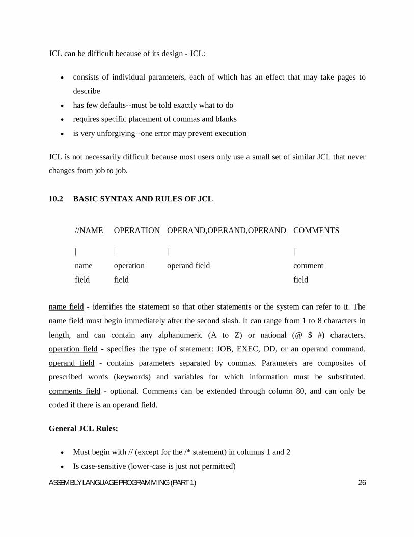
10.2 BASIC SYNTAX AND RULES OF JCL
//NAME OPERATION OPERAND,OPERAND,OPERAND COMMENTS
|
name
field
|
operation
field
|
operand field
|
comment
field
name field - identifies the statement so that other statements or the system can refer to it. The
name field must begin immediately after the second slash. It can range from 1 to 8 characters in
length, and can contain any alphanumeric (A to Z) or national (@ $ #) characters.
operation field - specifies the type of statement: JOB, EXEC, DD, or an operand command.
operand field - contains parameters separated by commas. Parameters are composites of
prescribed words (keywords) and variables for which information must be substituted.
comments field - optional. Comments can be extended through column 80, and can only be
coded if there is an operand field.
General JCL Rules:
Must begin with // (except for the /* statement) in columns 1 and 2
Is case-sensitive (lower-case is just not permitted)
ASSEMBLY LANGUAGE PROGRAMMING (PART 1) 27
NAME field is optional
must begin in column 3 if used
must code one or more blanks if omitted
OPERATION field must begin on or before column 16
OPERATION field stands alone
OPERANDS must end before column 72
OPERANDS are separated by commas
All fields, except for the operands, must be separated by one blank.
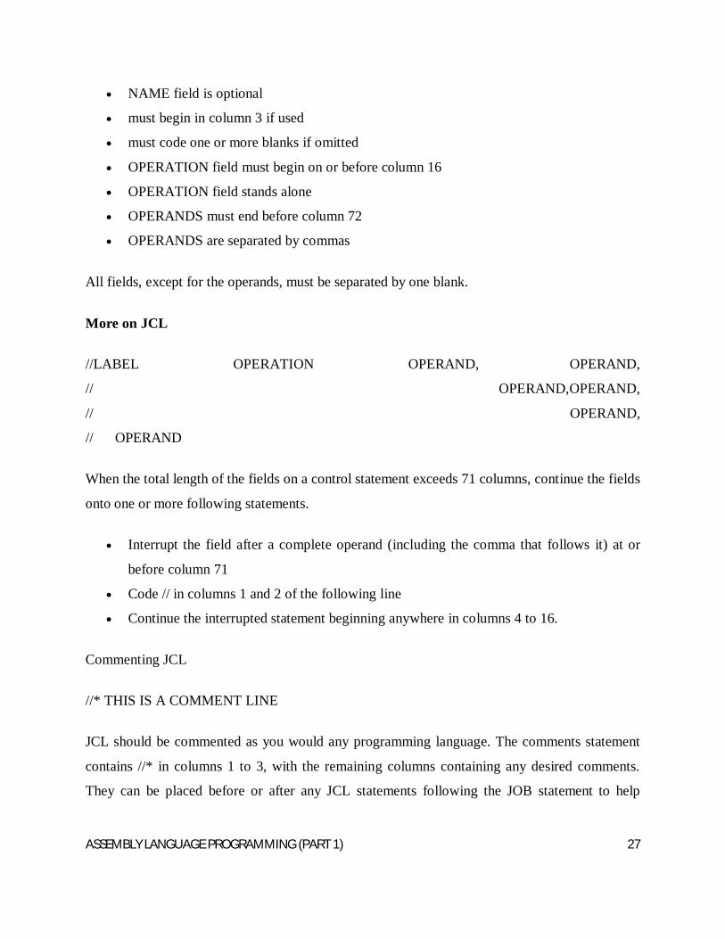
More on JCL
//LABEL OPERATION OPERAND, OPERAND,
// OPERAND,OPERAND,
// OPERAND,
// OPERAND
When the total length of the fields on a control statement exceeds 71 columns, continue the fields
onto one or more following statements.
Interrupt the field after a complete operand (including the comma that follows it) at or
before column 71
Code // in columns 1 and 2 of the following line
Continue the interrupted statement beginning anywhere in columns 4 to 16.
Commenting JCL
//* THIS IS A COMMENT LINE
JCL should be commented as you would any programming language. The comments statement
contains //* in columns 1 to 3, with the remaining columns containing any desired comments.
They can be placed before or after any JCL statements following the JOB statement to help
ASSEMBLY LANGUAGE PROGRAMMING (PART 1) 28
document the JCL. Comments can also be coded on any JCL statement by leaving a blank field
after the operand field.
10.3 TYPES OF JCL STATEMENTS
JOB Identifies the beginning of a job
EXEC Indicates what work is to be done
DD Data Definition, i.e., Identifies what resources are needed and where to find them
10.4 THE JOB STATEMENT
The JOB statement informs the operating system of the start of a job, gives the necessary
accounting information, and supplies run parameters. Each job must begin with a single JOB
statement.//jobname JOB USER=userid
jobname - a descriptive name assigned to the job by the user which is the banner on your printout
- any name from 1 to 8 alphanumeric (A-Z,0-9) or national ($,@,#) characters
- first character must be alphabetic or national
JOB - indicates the beginning of a job
Userid - a 1 to 7 character user identification assigned to access the system
10.5 THE EXEC STATEMENT
Use the EXEC (execute) statement to identify the application program or cataloged or in-stream
procedure that this job is to execute and to tell the system how to process the job.
//stepname EXEC procedure,REGION=####K
or
//stepname EXEC PGM=program,REGION=####K
ASSEMBLY LANGUAGE PROGRAMMING (PART 1) 29
stepname - an optional 1 to 8 character word used to identify the step
EXEC - indicates that you want to invoke a program or cataloged procedure
procedure - name of the cataloged procedure to be executed
program - name of the program to be executed
REGION=####K - amount of storage to allocate to the job
10.5 DATA DEFINITION (DD) STATEMENT
A DD (Data Definition) statement must be included after the EXEC statement for each data set
used in the step. The DD statement gives the data set name, I/O unit, perhaps a specific volume
to use, and the data set disposition. The system ensures that requested I/O devices can be
allocated to the job before execution is allowed to begin.
The DD statement may also give the system various information about the data set: its
organization, record length, blocking, and so on.
//ddname DD operand,operand,etc.
ddname - a 1 to 8 character name given to the DD statement
DD - DD statement identifier
operand - parameters used to define the input or output dataset
The DD Statement
appears after an EXEC statement
gives the system information on many things, including the dataset attributes, the
disposition of the dataset when the job completes, and which input/output device(s) to use
Happy Lecture

ASSEMBLY LANGUAGE PROGRAMMING (PART 1) 30