Embed Size (px)
Citation preview
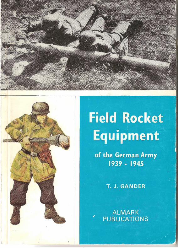
© 1972, Almark Publishing Co. Ltd.
Text © T. J . Gander
All rights reserved. No part of this publication ma y be reproduced. stored in
n relrieval system, or transmilled by any means, electronic, mechanical or by photo copying without p rior permission from the publishers.
First published - October 1972
ISBN 855240849 (hard cover edition)
ISBN 85524 085 7 (paper covered edition)
Printed in Great Britain by Byron Press Ltd., 59 Palmerston Road, Wealdstone, Middlesex
for the publishers, Almark Publishing Co. Ltd., 270 Burlington Road, New Malden, Surrey KT3 4N L, England
2
Introduction
TH E solid fuel rocket is no newcomer to modern warfare for its first recorded use in battle dates back to AD 1232, but after the fall from grace of the Congreve and Hale rockets towards the end of the nineteenth century little use was made of it until the German Army re - introduced the rocket in an offensive role from 1940 onwards . Actually they could have had rockets in service during World War I, for Krupps had purchased the solid fuel rocket patents of the Swedish experimenter Lieutenant-Colonel von Unge in 1909. While the rockets then produced w ere extensively tested , they did not go into production as they were virtually hand-made and the slow-burning black powder propellants then in use were prone to damage during storage and transport . This damage manifested itself in erratic burning and general unreliability. It was not until the advent of the large grain double-based propellants after about 1935 that a storeable and reliable mass-produced rocket could be manufactured.
This book sets out to show how one nation, Germany, employed the solid fuel rocket as part of its national field armoury. As such it confines itself to weapons used on the battlefield and only encroaches onto the anti aircraft role when the rockets so employed were also used as ground-toground w eapons. However, to 'complete the story' in some cases, mention has been made of the airborne use of some of these weapons.
The research into this subject has been considerably aided by John Milsom who supplied much of the material used in this book, and to whom my thanks are due. Acknowledgements and thanks must also be made to R. C. Gibson, John Wilkes, Colour Sergeant Fitch of the Airborne Forces Museum at Aldershot, Peter Chamberlain, the staff of the Photographic Sec tion of the Imperial War Museum, and finally my wife who typed the original manuscript. Kenneth M . Jones produced the cover art .
CONTENTS
Section Page
1: Deployment and Organisation 5 2: Rocket Equipment 14
3
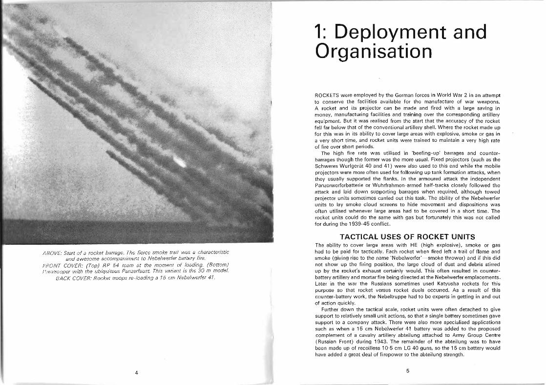
/lBO VE: Start of a rocket barrage. The fierce smoke trail was a characteristic and awesome accompaniment to Nebelwerfer battery fire.
FRONT COVER: (Top) RP 54 team at the moment of loading. (Bottom) I'ilrarrooper with the ubiquitous Panzerfaust. This variant is the 30 m model.
BA CK COVER: Rocket troops re -Ioading a 15 cm Nebelwerfer 41.
4
1: Deployment and Organisation
ROCKETS were employed by the German forces in World War 2 in an attempt to conserve the facilities available for the manufacture of war weapons. A rocket and its proj ector can be made and fired with a large saving in money, manufacturing facilities and training over the corresponding artillery equipment. But it was realised from the start that the accuracy of the rocket fell far below that of the conventional artillery shell. Where the rocket made up for this was in its ability to cover large areas with explosive, smoke or gas in a very short time, and rocket units were trained to maintain a very high rate of fire over short periods.
The high fire rate was utilised in 'beefing-up' barrages and counterbarrages though the former was the more usual. Fixed projectors (such as the Schweres Wurfgeriit 40 and 41) were also used to this end while the mobile projectors were more often used for following up tank formation attacks, when they usually supported the flanks . In the armoured attack the independent Panzerwerferbatteri e or Wuhrfrahmen -armed half-tracks closely followed the attack and laid down supporting barrages when required, although towed projector units sometimes carried out this task. The ability of the Nebelwerfer units to lay smoke cloud screens to hide movement and dispositions was often utilised whenever large areas had to be covered in a short time. The rocket units could do the same with gas but fortunately this was not called for during the 1939-45 conflict .
TACTICAL USES OF ROCKET UNITS The ability to cover large areas with HE (high explosive), smoke or gas had to be paid for tactically. Each rocket when fired left a trail of flame and smoke (giving rise to the name 'Nebelwerfer'-smoke thrower) and if this did not show up the firing position, the large cloud of dust and debris stirred up by the rocket's exhaust certainly would. This often resulted in counterbattery artillery and mortarfire being directed at the Nebelwerfer emplacements. Later in the war the Russians sometimes used Katyusha rockets for this purpose so that rocket versus rocket duels occurred. As a result of this counter-battery work, the Nebeltruppe had to be experts in getting in and out of action quickly.
Further down the tactical scale, rocket units were often detached to give support to relatively small unit actions, so that a single battery sometimes gave support to a company attack. There were also more specialised applications such as when a 15 cm Nebelwerfer 41 battery was added to the proposed complement of a cavalry artillery abteilung attached to Army Group Centre (Russian Front) during 1943. The remainder of the abteilung was to have been made up of recoilless 10'5 cm LG 40 guns, so the 15 cm battery would have added a great deal of fi repower to the abteilung strength.
5
ORGANISATION OF 'DIE NEBElTRUPPEN' Up to 1940 the main weight of the German Chemical Warfare Units was biased towards smoke production for tactical screens. The units involved were few in number and utilised the 10 cm Nebelwerfer 35-an enlarged mortar (for details see separate section) . In 1940 this was supplemented by the 10 cm Nebelwerfer 40 but by the same year the first rocket equipments (the Schweres Wurfgerat 40 with its 28/ 32 cm rockets) came into service after development at Meppen and Kummersdorf.
However, during 1939 the first Nebeltruppe were amongst the German forces invading Poland, but there was little for them to do. There were in fact three Nebelabteilung present during that campaign. As the rocket equipments became available a training unit (Lehrabteilung) was formed at the Nebeltruppenschule at Celie, south of Stettin but the first Werfer Regiment was not formed until June 1940-just too late to take part in the campaign in France, After that, however, th e numbers of Werferbrigaden (each made up of two or three Werferregimenter) increased until there were twenty in the line and numerous other units available for special purposes such as the Panzerwerferbatterie and Rheinbote units. A second training unit and range was at Munster- Nord.
ESTABLISHMENTS Basically there were three different types of rocket unit, of which the basic unit was the Abteilung (artillery brigade) . These abteilung were joined in differing combinations to form Werferregimenter. The three basic abteilung were as follows. (1) Rocket Projector Brigade (Motorized). (Werferabteilung [mot]).
Normally equipped with the 15 cm Neberwerfer 41 this formation consisted of a brigade staff and staff battery with up to three batteries (werferbatterien), The equipment for this unit is shown separately, but the staff consisted of:
Brigade HQ Reconnaissance/ observation platoon Rangefinder section. Maintenance unit Ad ministrative staff Signals staff Anti-tank unit, armed with the 3·7 cm or later the 7·5 cm Pak.
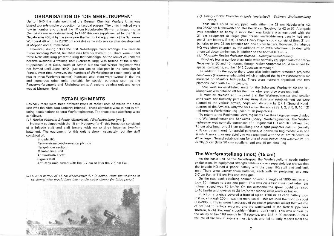
BEL 0 W: A battery of 15 cm Nebelw erfer 41 s in action. Note the absence of p ersonnel who would ha ve been under cover during the firing period.
(2) Heavy Rocket Projector Brigade (motorized}-Schwere Werferabteilung (mot) .
These units could be equipped with either the 21 cm Nebelwerfer 42, the 28/ 32 cm Nebelwerfer or later the 30 cm Nebelwerfer 42 or 56. A brigade was described as heavy if more than one battery was equipped with the 21 cm equipment or larger (the normal werferabteilung usually had only one 21 cm battery, if that). Thus a Heavy Brigade could consist of three 21 cm batteries or two 21 cm batteries and one 15 cm battery. However, the brigade HQ was often enlarged by the addition of an extra detachment to deal with chemical decontamination, in addition to the normal HQ units. (3) Mountain Rocket Projector Brigade-Gebirgswerferabteilung.
Relatively few in number these units were normally equipped with the 10 cm Nebelwerfer 35 and 40 mortars, though rocket equipment could be added for special campaigns, eg, the 1942 Caucasus campaign.
In addition to the above there were also independent armoured projector companies (Panzerwerferbatterie) which employed the 15 cm Panzerwerfer 42 mounted on Maultier half-tracks, These were normally organised into two platoons, each with four projectors.
There were no established units for the Schweres Wurfgeriit 40 and 41 . Manpower was detailed off for their use whenever they were required.
It must be stressed at this point that the Werferregimenter and smaller units were not normally part of any Army divisional establishment but were allotted to the various armies, corps and divisions by OKH (General Headquarters of the Armies). Only the SS Panzer Divisions (SS 1, 2, 3, 5, 9, 10, 12) had organic Werferabteilung (each of 18 projectors) .
To return to the Regimental level, regiments like their brigades were divided into Werferregimenter and Schweres (heavy) Werferregimenter. The W erferregimenter was normally comprised of a Regimental HQ and HQ battery, two 15 cm abteilung, one 21 cm abteilung and a light projector column (usually a 15 cm detachment) for special purposes. A Schweres Regimenter was one in which more than one abteilung was equipped with the 21 cm Nebelwerfer 42 or larger. Normal establishment for one of these heavy units was two 21 cm or 28/32 cm (later 30 cm) abteilung and one 15 cm abteilung.
The Werferabteilung (mot) (15 em) As the basic unit of the Nebeltruppe, the W erferabteilung needs further
explanation . Its equipment strength table is shown separately but shows that the brigade HQ had a 'paper' battery with the usual HQ staff and anti -tank unit. There were usually three batteries, each with six projectors, and one 3 ·7 cm Pak or 7·5 cm Pak anti-tank gun.
On the road each abteilung column covered a length of 1800 metres and took 20 minutes to pass one point. This was on a first class road when the column speed was 30 km/hr. On the autobahn the speed could be raised to 40 km/ hr and lowered to 20 km/ hr for second class roads or tracks.
In action a brigade covered a front of up to 1200 m, as each battery took 350 m, although 200 m was the more usual-this reduced the front to about 800-900 m. The inherent inaccuracy of the rocket projectile meant that volume of fire had to replace accuracy and the watchword of the Nebeltruppe was 'Klotzen, Nicht Kleckern' (roughly-'thump, don't tap'). This was shown by the ability to fire 108 rounds in 10 seconds, and 648 in 90 seconds. Such a volume of fire would saturate most targets and led to early reports from the
7
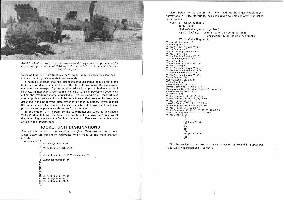
ABOVE: Maultiers with 15 cm Panzerwerfer 42 projectors being prepared for action during the winter of 1944. Note rhe discarded 'packkiste' at the bottom
left of the picture.
Russians that the 15 cm Nebelwerfer 41 could fire 6 rockets in five secondsactually the firing rate was six in ten seconds.
It must be stressed that the establishments described above and in the tables are for ideal situations. Even at the start of a campaign the manpower, equipment and transport figures could be reduced by up to a third as a result of sickness, maintenance, unserviceability, etc. By 1945 manpower had become so critical that Werferregimenter consisted of two abteilung only. Transport was another problem area and it should be borne in mind that many of the projectors described in this book were often towed into action by horses. However most SS units managed to maintain a higher establishment of equipment and manpower due to the preference shown to Party formations.
In September 1944, certain of the Werferabteilung were re-designated Volks-Werferabteilung . The term had purely political overtones in view of the impending defence of the Reich, and made no differences to establishments or role in the Nebeltruppen.
ROCKET UNIT DESIGNATIONS Few records remain of the Nebeltruppen (later Werfertruppe) formations. Listed below are the known regiments which made up the Werferbrigaden in 1945:
Werferbrigade 1 2 Werfer Regi menter 3, 70 3 4 Werfer Regi menter 51, 52, s2 5 6 7 Werfer Regimenter 83, 84 (Normandy July '44) 8 9 Werfer Regimenter 14, 54
10 11 12 13 14 15 16 Werfer Regimenter 86, 87 17 Werfer Regimenter 88, ? 18 Werfer Regimenter 21, 22 19 20
8
Listed below are the known units which made up the larger Nebeltruppen formations in 1945. No priority has been given to unit seniority. The list is not complete .
Note: s-schweres (heavy) Stab-Staff. Stell-Stellung (static, garrison) (mit 21 [pz] Bttr)-with 21 battery made up of 15cm
Panzerwerfer 42 on Maultier half-tracks. WR- Werfer Regiment.
Werfer Lehr Regiment 1, 2 Werfer Regimen t s 1 Werfer Abteilung 1 (with WR 54) Werler Regiment s 2 Werfer Abteilung 2 (with WR 52) Werfer Regiment s 3 Werfer Abteilung 3 (with WR s3) Stab Werfer Regiment z b V 4 Werfer Abteilung 4 Werfer Abteilung 5 (with WR 55) Werfer Abteilung 6 Werfer Abteilung 7 (with WR 54) Werfer Abteilung 8 (with WR s 2) Stab Werfer Regiment s b V 8 Werfer Abteilung 9 (with WR 71) Werfer Regiment 10 Gebirgs Werfer Abteilung 10 Werfer Abteilung 11 s Werfer Regimenter 13. 14, 15 Panzer Werfer Bam 21 (with WR 57) Panzer Werfer Battr 22 (with 15 Panzer Grenadier Div) s Werfer Regimenter 21, 22, 26 Werfer Abteilung 31 Werfer Regimenter 38. 50, 51, 52 53 Werfer Regiment 54 (mit 21 [pz] Battr) Werfer Regiment 55, 56 s Werfer Reg iment 57 (mit 21 [pz] Battr) Werfer Reg iment 70 (mit 21 [pz] Battr) Werfer Regiment 71 (Tunisia '43) Werfer Regimenter 77,79,81,83,84,86,87,88,89 Stell Werfer Regimenter 100, 101, 102, 103 Werfer Batlerien 105
113 114 151 (with WR 70) 203 208 211 224 287 (with WR 56) 408 458
The Smoke Units that took part in the Invasion of Poland in September 1939 were Nebelabteilung 1, 2 and 5.
9
--------I..-....~==..........'--";o...;;;;,...------------------r----------------~------..-.. Rocket Projector Regiment (motorized)
Werferregimenter (mot)
UNIT
(f)
c :J Ol
Qi Q)
, c c 0 <:: _:E (f) .c u Q; Ol C1l
a.. ::J~
.Xc
~ .~
C1l
E u (f)
c LO :J
"(.!J
(f) Q)
u
0 (f)
U >
Q)o ou (f)
0 Q)
.X- Q) u .- -i: o e o Q) 0
0::0... ~> ~
Regimental HO......... . ... . .... 31 7 3 Regimental HO Battery . .. ...... 110 2 20 2 Projector Battalion 555 20 4 18 109 9
Projector Battalion ........ . ... 555 20 4 18 109 9 Projector Battalion ......... . . 555 20 4 18 109 9 Light Projector Column ...... . 70 20 5
Total ... . . ................ ... 1,876 62 12 54 374 37
Total strength 1,876
Rocket Projector Battalion (motorized) Weferabteilung (mot)
UNIT
(f) (f) c
(f) C :J Q) :J Ol (f)c Ol, Q, <:: ii Q) c :J
u ro c .c Ol
.<;; u r u C1l «
(f) (f) C1l0 ~ (f)Q; (f) ~ (f) ~ E ....U 0 C1l Q) 0 .c U > t) ..0 LO:i: u ~ :J Ol
0 Z a: 0:: a.. (f) ::J "
8 (f)
(f) Q)u (f)
Q).e- .~ Q)
.<;; u Q) >a.. > U
Q) 0 0.Xu 0 0 0
0:: ~ ~
1I"II,Ii">I' 110 . . ............. 2 3 10 10 3 2 3 1 11"II,IiII>'1 110 l3,lttery ..... . .. . . . . 3 12 70 70 9 6 2 13 2 1' 1111.,4 .1111 nllllllry. . . . . . .. .... 3 27 105 113 10 12 6 6 31 2
I', "I, " I"' 1I"II"ry 3 27 105 113 10 12 6 6 31 2 l ' j i ' I' ll llti 1IIIIIoly .. " ........... . .. 3 27 105 113 10 12 6 6 31 2 A lli""",III""" 1;"I0""n .... . . ...... 5 45 45 2 3
1111 ,, 1 .. . . . . . .. . . ... 14 101 440 464 44 47 20 4 18 109 9
Total strength 555
10
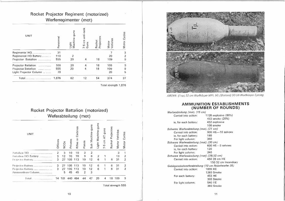
ABOVE: (Top) 32 em Wurfkorper MFL 50. (Bottom) 30 em Wurfkorper Spreng.
AMMUNITION ESTABLISHMENTS (NUMBER OF ROUNDS)
Werferabteilung (mot) (15 em) Carried into action: 1728 explosive (80%)
432 smoke (20%) ie, for each battery: 432 explosive
108 smoke Sehwere Werferabteilung (mot) (21 em)
Carried into action: 900 HE-10 salvoes ie, for each battery: 180 For light column: 360
Sehwere Werferabteilung (mot) (30 em) Carried into action: 600 HE-3 salvoes ie, for each battery: 120 For light column: 240
Sehwere Werferabteilung (mot) (28/32 em) Carried into action: 45028 cm HE
150 32 cm Incendiary Gebirgsnebelwerferabteilung (10 em Nebelwerfer 35)
Carried into action: 1899 HE 1269 Smoke
For each battery: 453 HE 303 Smoke
For light column: 540 HE 360 Smoke
11
:;
'"' .' ,~.~~;c? ;.. ,:~~;,-'.:. ;.\~~~:~~%~
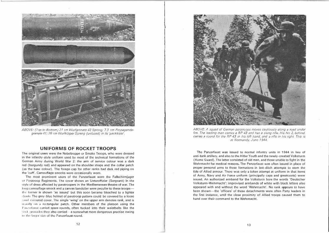
ABOVE: (Top to Bottom) 21 em Wurfgrenate 42 Spreng; 7.3 cm Propagandagranare 41; 28 cm Wurfkorper Spreng (unfused) in its 'packkiste '.
UNIFORMS OF ROCKET TROOPS The original users were the Nebeltruppe or Smoke Troops, who were dressed in the infantry-style uniform used by most of the technical formations of the German Army during World War 2: the arm of service colour was a dark red (burgundy red) and appeared on the shoulder straps and the collar patch (as t he base colour). The forage-cap for other ranks had dark red piping on the 'cuff. Camouflage smocks were occasionally worn .
The most prominent users of the Panzerfaust were the Fallschirmjager or Paratroop Regiments. The cover shows an Unteroffizier (Sergeant) in the slyle of dress affected by paratroopers in the Mediterranean theatre of war. The Inlln camouflage smock and a canvas bandolier were peculiar to these troopslilt : former is shown 'as issued' but this soon became bleached to a lighter :: 11 :1(1 0. The grey-blue helmet of paratroop pattern could be covered by a loose :;' "11 I coloured cover. The single 'wing' on the upper arm denotes rank, and is ,,;.,,;olly lin ,I rectangular patch. Other members of the platoon using the 1""' ''t: rI ; lIl ~t c,mied spare rounds, often tucked into their waistbelts like the :;111;1, qrllll ; ld c~ they also carried- a somewhat more dangerous practise owing II I 111 " li llllm sizo of th e Panzerfaust round.
12
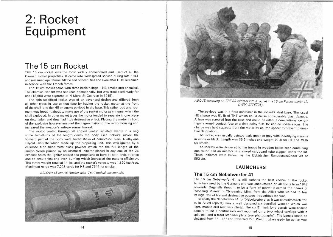
ABOVE: A squad of German paratroops moves caurio usly along a road under fire. The leading man carries a RP 43 and has a slung rifle. His No 2. behind. carries a round fer rhe RP 43 in his lefr hand, and a rifle in his right. This is
at Normandy, June 1944.
The Panzerfaust was issued to normal infantry units in 1944 in lieu of anti-tank artillery, and also tothe Hitler Youth and the newly-created Volksturm (Home Guard) . The latter consisted of old men, and those unable to fight in the Wehrmacht for medical reasons. The Panzerfaust was often issued in place of proper personal arms to these formations in last-ditch attempts to stem the tide of Allied armour. There w as only a token attempt at uniform in that items of Army, Navy and Air Force uniform (principally caps and greatcoats) were issued. An authorized armband for the Volksturm bore the words ' Deutscher Volksturm-Wehrmacht': improvised armbands of white with black letters also appeared with and without the word 'Wehrmacht' . No rank appears to have been shown- th e 'officers' of these detachments were often Party leaders in the first instance, until the close proximity of Allied troops caused them to hand over their command to the Wehrmacht.
13
2: Rocket Equipment
The 15 cm Rocket TH E 15 cm rocket was the most widely encountered and used of all the German rocket projectiles. It came into widespread service during late 1941 and remained operational till the end of hostilities and even after 1945 remained in service with the French forces.
The 15 cm rocket came with three basic fillings-HE, smoke and chemical. The chemical variant was not used operationally, but was stockpiled ready for use (18,600 were captured at H Muna 5t Georgen in 1945).
The spin stabilized rocket was of an advanced design and differed from all other types in use at that time by having the rocket motor at the front of the shell and the HE or smoke payload in the base. This rather odd arrangement was brought about to make use of the rocket motor as shrapnel when the shell exploded . In other rocket types the motor tended to separate in one piece on detonation and thus had little destructive effect. Placing the motor in front of the explosive however ensured the fragmentation of the motor housing and increased the weapo'n's anti-personnel hazard.
The motor vented through 26 angled venturi situated evenly in a ring some two-thirds of the length down the body (see below) . Inside the forward part of the body were seven sticks of compresed black Diethylene Glycol Dinitrate which made up the propelling unit. This was ignited by a cellulose tube filled with black powder which ran the full length of the motor. When primed by an electrical initiator placed in anyone of the 26 exhaust holes the igniter caused the propellant to burn at both ends at once and so ensure fast and even burning which increased the motor's efficiency. The motor weight totalled 14 Ibs and the rocket's velocity was 1,120 feet / sec. Maximum range was 7,723 yards for HE and 7546 for smoke.
BELOW: 75 em HE Rocket with 'Tp': Tropical use stencils.
14
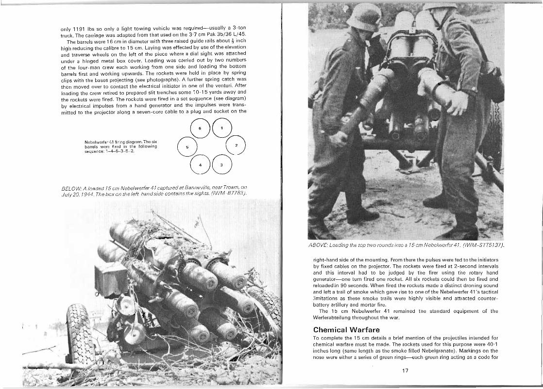
ABOVE: Inserting an ERZ 39 initiator into a rocket in a 75 em Panzerwerfer 42. (IWM-STT5705).
The payload was in a fibre container in the rocket's steel base. The usual HE charge was 5~ Ib of TNT which could cause considerable blast damage. A fuse was screwed into the base and could be either a conventional centrifugally armed contact fuse or a time delay fuse for use on fortifications. The charge was held separate from the motor by an iron spacer to prevent premature detonation.
The rocket was usually painted dark green or grey with identifying stencils in white or black. Length was 36·6 inches and weight 70 Ib for HE and 79 Ib for smoke.
The rockets were delivered to the troops in wooden boxes each containing one round and an initiator in a waxed cardboard tube clipped under the lid. These initiators were known as the Elektrischer Randdusenzunder 39 or ERZ 39.
LAUNCHERS
The 15 em Nebelwerfer 41 The 15 cm Nebelwerfer 41 is still perhaps the best known of the rocket launchers used by the Germans and was encountered on all fronts from 1942 onwards. Originally thought to be a form of mortar it earned the names of 'Moaning Minnie' or 'Screaming Mimi ' from the Allies who learned to fear its high rate of fire and destructive powers throughout the war.
Basically the Nebelwerfer 41 (or 'Nebelwerfer d' as it was sometimes referred to in Allied reports) was a well designed six-barrelled weapon which was light, mobile and relatively cheap. The six 51 inch long barrels were spaced equally round a central axis and mounted on a two wheel carriage with a split trail and a front stabiliser plate (see photographs). The barrels could be elevated from 5°_45 ° and traversed 27 °. Weight when ready for action was
15
only 1191 Ibs so only a light towing vehicle was required- usually a 3-ton truck . The carriage was adapted from that used on th e 3·7 cm Pak 35/36 L/45.
The barrels were 16 cm in diameter with three raised guide rails about t inch high reducing the calibre to 15 cm. Laying was effected by use of the elevation and traverse wh eels on th e left of th e piece where a dial sight was attached under a hinged metal box cover. Loading was carried out by two numbers of the four-man crew each working from one side and loading the bottom barrels first and working upwards. The rockets were held in place by spring clips with the bases projecting (see photographs). A further spring catch was then moved over to contact the electrical initiator in one of th e venturi. After loading the crew retired to prepared slit trenches some 10- 15 yards away and the rockets were fired. The rockets were fired in a set sequence (see diagram) by electrical impulses from a hand generator and the impulses were trans mitted to the projector along a seven-core cable to a plug and socket on the
00 Nebelwerfer 41 firin g diagram. The six barrels were fired in th e follow ing sequ ence: 1-4-6-3-5-2. a 0
GO BELOW: A loaded 15 cm Nebelwerfer 41 captured at Bannevi/le, near Troam, on July 20, 1944. The box on the left-hand side contains the sigh ts. (IWM -B7783) .
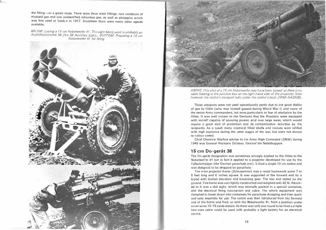
ABOVE: Loading the top two rounds into a 15 cm Nebelwerfer 41 . (IWM-STT5137J.
right- hand side of the mounting. From there the pulses were fed to the initiators by fixed cables on the projector. The rockets were fired at 2-second intervals and this interval had to be judged by th e firer using the rotary hand generator-one turn fired one rocket. All six rockets could then be fired and reloaded in 90 second s. When fired the rockets made a distinct droning sound and left a trail of smoke which gave rise to one of the Nebelwerfer 41 's tactical limitations as these smoke trails were highly visible and attracted counterbattery artillery and mortar fire.
The 15 cm Nebelwerfer 41 remained the sta ndard equipment of th e Werferabteilung throughout the war.
Chemical Warfare To complete the 15 cm details a brief mention of the projectiles intended for chemical warfare must be made. The rockets used for this purpose were 40·1 inches long (same length as the smoke filled Nebelgranate) . Markings on the nose were either a series of green rings--each green ring acting as a code for
17
the filling-or a green cross. There were three main fillings, two variations of mustard gas and one unidentified odourless gas, as well as phosgene which was first used at Verdun in 1917. Doubtless there were many other agents available.
BEL OW: Laying a 75 em Nebelwerfer 47. The sight being used is probably an Aushilfsrichtmittel38 (No 38 Auxiliary sight) . BOTTOM: Prepanng a 75 em
Nebelwerfer 47 for firing.
ABOVE: This shot of a 75 em Nebelwerfer may have been 'posed' as there is no cable leading to the junction box on the right-hand side of the projector. Nore ho wever the rocker's rransp0r/ tube under the soldier's boot. (IWM-NA2628).
These weapons were not used operationally partly due to the great dislike of gas by Hitler (who was himself gassed during World War I) and many of the senior Army commanders, but more particularly to fear of retaliation by the Allies. It was well known to the Germans that the Russians were equipped with aircraft capable of spraying prussic acid over large areas, which would require a great deal of protection and de-contamination activities by the recipients. As a result many chemical filled shells and rockets were refilled with high explosive during the latter stages of the war, but were not always re-colour coded.
Chief Chemical Warfare adviser to the Army High Command (OKW) during 1945 was General Hermann Ochsner, General die Nebeltruppen.
15 em Do-gerat 38 The Do-geriit designation was sometimes wrongly applied by the Allies to the Nebelwerfer 41 but in fact it applied to a projector developed for use by the Fallschirmjiiger (the German parachute arm). It fired a single 15 cm rocket and was designed to be dropped by parachute.
The main projector frame (Schiessrinne) waS a metal framework some 7 to 8 feet long and 6 inches square. It was supported at the forward end by a bipod with limited elevation and traversing gear. The rear end rested on the ground. This frame was very lightly constructed and weighed only 421b. Attached to it was a dial sight, which was normally packed in a special container, and the electrical firing mechanism and cable. The whole equipment was designed to break down into containers for parachute dropping and then quick nnd easy assembly for use. The rocket was then introduced from the forward end of the frame and fired, as with the Nebelwerfer 41, from a position under cover some 10-15 yards distant. As there was only one round to be fired a simple two -core cable could be used with probably a light battery for an electrical sOllrce.
19
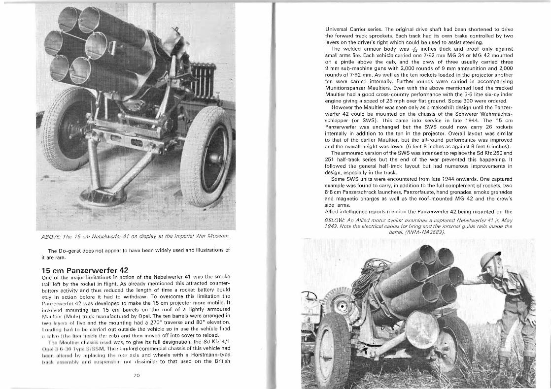
ABOVE: The 15 em Nebelwerfer 41 on display at the Imperial War Museum.
The Do-geriit does not appear to have been widely used and illustrations of it are rare.
15 em Panzerwerfer 42 One of the major limitations in action of the Nebelwerfer 41 was the smoke trail left by the rocket in flight . As already mentioned this attracted counterbilttery activity and thus reduced the length of time a rocket battery could slily in action before it had to withdraw. To overcome this limitation the 1':lIm,rwcrfer 42 was developed to make the 15 cm projector more mobile. It ill v() lvoci mounting ten 15 cm barrels on the roof of a lightly armoured IVI:llilli'lr (Milk) truck manufactured by Opel. The ten barrels were arranged in 1"'11/ lilY" ,:. "r fivll ilnd the mounting had a 270 0 traverse and 80 0 elevation. 1,,,,0111111 1:,,:1 III Ito c:mi"d out outside the vehicle so in use the vehicle fired II 11 11 ill II (11",11,,,, illi lid o II I(: cab ) and then moved off into cover to reload.
II" , J\!l, lIlli l,'1 "III' ·H.'" 11 ',"e l W:1S, to give its full designation, the Sd Kfz 4/1 1'1," 1 I I! II I I VI' '' '~/:l!l lV1 , I h" ::I:IIHI:lrd commercial chassis of this vehicle had 1, ,111 11 Id ll ll,, 01 Ily '''1' 11 11 il1l1 11,\" HI: II' ilxl e wnd wheels with a Horstmann-type 1111, I' " ~II I' lI o1 jl y 11 1,,1 1111"1''''' ' '\111\ ,,"I dissimilar to that used on the British
J()
Universal Carrier series. The original drive shaft had been shortened to drive the forward track sprockets . Each track had its own brake controlled by two levers on the driver's right which could be used to assist steering.
The welded armour body was TI inches thick and proof only against small arms fire. Each vehicle carried one 7 ·92 mm MG 34 or MG 42 mounted on a pintle above the cab, and the crew of three usually carried three 9 mm SUb-machine guns with 2,000 rounds of 9 mm ammunition and 2,000 rounds of 7 ·92 mm . As well as the ten rockets loaded in the projector another ten were carried internally. Further rounds were carried in accompanying Munitionspanzer Maultiers. Even with the above mentioned load the tracked Maultier had a good cross-country performance with the 3·6 litre six-cylinder engine giving a speed of 25 mph over flat ground. Some 300 were ordered.
However the Maultier was seen only as a makeshift design until the Panzerwerfer 42 could be mounted on the chassis of the Schwerer Wehrmachtsschlepper (or SWS). This came into service in late 1944. The 15 cm Panzerwerfer was unchanged but the SWS could now carry 26 rockets internally in addition to the ten in the projector. Overall layout was similar to th at of the earlier Maultier, but the all-round performance was improved and the overall height was lower (6 feet 8 inches as against 8 feet 6 inches).
The armoured version of the SWS was intended to replace the Sd Kfz 250 and 251 half-track series but the end of the war prevented this happening. It followed the general half-track layout but had numerous improvements in design, especially in the track.
Some SWS units were encountered from late 1944 onwards. One captured example was found to carry, in addition to the full complement of rockets, two 8,8 cm Panzerschreck launchers, Panzerfauste, hand grenades, smoke grenades and magnetic charges as well as the roof-mounted MG 42 and the crew's side arms. Allied intelligence reports mention the Panzerwerfer 42 being mounted on the
BELOW: An Allied motor cyclist examines a captured Nebelwerfer 41 in May 1943. Note the electrical cables for flfing and the internal guide rails inside the
barre/. (IWM-NA2583).
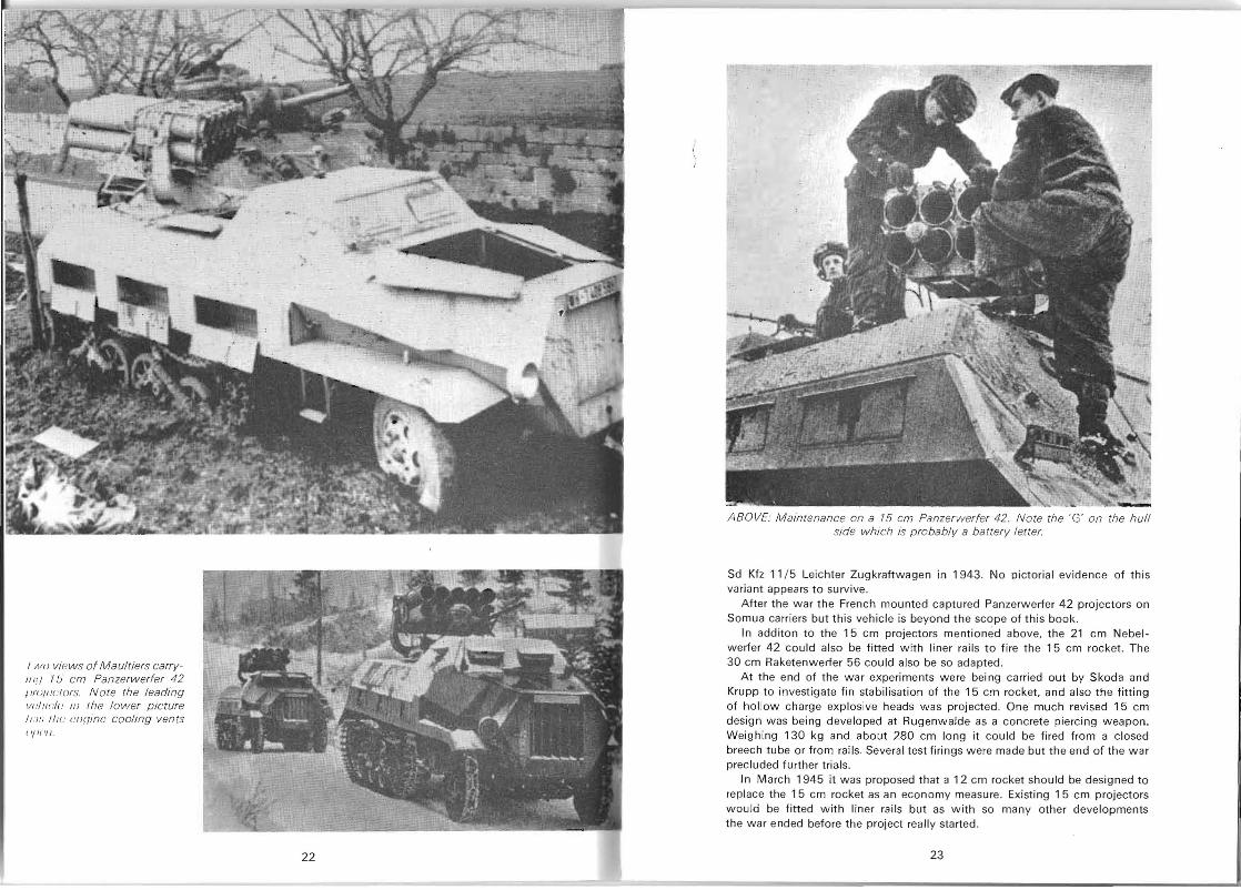
I WI! views of Maultiers carryIIl11 I IJ' cm Panzerwerfer 42 I I/lil1.'1.'1ors. Note the leading vI.'I 11'';/1.' III Ihe lower picture /1. ' /." IllI.' conine cooling vents I 'I If 'II .
22
ABOVE: Maintenance on a 75 cm Panzerwerfer 42. Note the 'G' on the hull side which is probably a battery letter.
Sd Kfz 11 / 5 Leichter Zugkraftwagen in 1943. No pictorial evidence of this variant appears to survive.
After the war the French mounted captured Panzerwerfer 42 projectors on Somua carr iers but this vehicle is beyond th e scope of this book.
In additon to the 15 cm projectors mentioned above, the 21 cm Nebelwerfer 42 cou ld also be fitted with liner rails to fire the 15 cm rocket . The 30 cm Raketenwerfer 56 could also be so adapted.
At the end of the war experiments were being carried out by Skoda and Krupp to investigate fin stabilisation of the 15 C!l1 rocket, and also the fitting of hollow charge exp losive heads wa s projected. One much revised 15 cm design was being developed at Rugenw alde as a concrete piercing weapon. Weighing 130 kg and about 280 cm long it cou ld be fired from a closed breech tube or from rails. Several test firings were made but the end of the war precluded fu rther trials.
In March 1945 it was proposed that a 12 cm rocket shou ld be designed to replace the 15 cm rocket as an economy measure. Existing 15 cm projectors would be fitted with liner rails but as with so ma ny other developments the war ended before the project really started.
23
The 21 cm Rocket The 21 cm Wurfgrenate 42 Spreng was developed and utilised alongside the 15 cm rocket. However in appearance it resembled a conventional artillery round as it was carefully streamlined by the addition of a false hollow nose (ogive) which did away with the usual blunt nose of most German rockets.
Layout of the rocket was conventional ie, the motor was at the rear and the warhead in front, both encased in a mild steel body. The motor was made up of seven propellant sticks, each 21·67 inches long, each stick 2-46 inches in diameter. A grid trap separated the propellant from the nozzle assembly and between the two was a tinfoil sealing disc to keep out moisture. Round th e edge of the nozzle assembly were 22 venturi angled at 16° from the rocket axis to impart the stabilising spin in flight. In the centre of the one-piece nozzle plate was a hole ready to take the ERZ 39 (Elektrische Randdusenzunder 39) initiator. When fired electrically the ERZ 39 would ignite a quickmatch relay through the centre of the motor to the black powder igniter at the front of the body. A small spacer ring held the igniter separate from the motor to ensure even burning . Weight of the motor was 87·75 Ib and the nozzle assembly 5 '12 lb. The propellant alone weighed 40·25 lb.
The 90 Ib warhead shell contained 22-4 Ib of TNT and was threaded onto the motor body. A point detonating fuse with an optional delay of 0 ·10 seconds was screwed into a booster cup in the nose. Connection to the fuse was made from the false ogive by a wooden rod .
Overall length of the rocket was 49·21 inches and the total weight was 241 ·3 Ibs. Only HE rockets appear to have been used in this calibre. Supplied to the front line in shaped mild steel 'cage' crates, they were painted black or dark grey with white stencilled markings.
LAUNCHERS
The 21 em Nebelwerfer 42 Originally intended to be an enlarged version of the six-barrelled 15 cm Nebelwerfer 41 . The 21 cm Nebelwerfer 42 ended up as a five-barrelled projector. However in all other respects it clearly resembled the 15 cm projector and even utilised the same 3·7 cm Pak derived carriage.
The decision to use the five-barrel layout was made because of the better balance and stability of the mounting when using the heavier 21 cm ammunition.
The 4 feet 3?, inch long barrels were spaced round a central axis and held in position by stamped steel plates-one near the breech and another half-way to the muzzle. Elevation and traverse controls were simple and actuated by pressed steel wheels on the left of the carriage. Elevation was from _5° to 45° and traverse 12° either side. As on the 15 cm equipment there was a split trail and a stabilising plate on the front of the axle. The wheels w ere stamped steel discs with 6·00/20 pneumatic tyres. Weight of the equipment was 12 cwt (605 kg). Maximum range of the projector was 8530
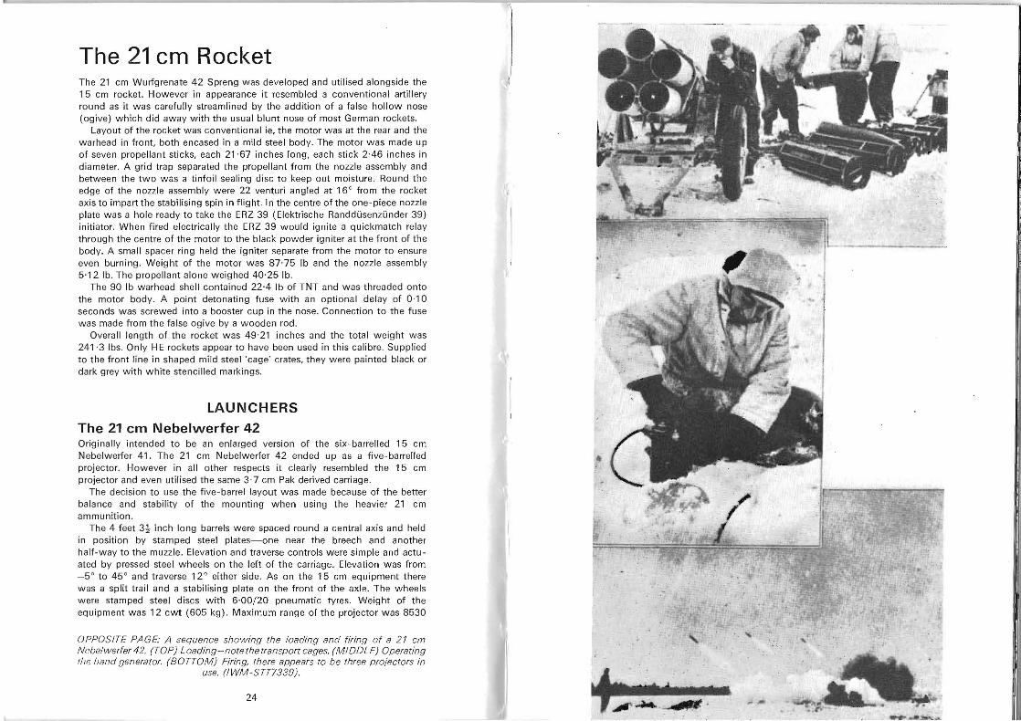
OPPOSITE PAGE: A sequence showing the loading and firing of a 21 cm Ncbelwerfer 42. (TOP) Loading-note the transport cages. (MIDDLE) Operating the hand generator. (BOTTOM) Firing, there appears to be three projectors in
use. (/WM-STT7339).
24
yards (7850 metres) according to range tables but some rockets managed to reach 1 0,000 yards on trials in North Africa.
Loading was effected from the rear. Wh en loaded the rocket rear was flush with the end of the barrel and held in position by spring-loaded catches. Firing was normally carri ed out electrically from a position under cover some 1 0 yards from the projector. connection to the electrical network on the barrels being made by a six-core cable via a junction box on the right-hand side of the mounting. The 0'3A initiating current came from a small hand generator. For firing order see diagram.
During 1944-45 the firms of Krupp and Skoda were both experimenting with fin stabilising of 21 cm rockets. The German surrender in May 1945 ended these experiments. Other experiments w ere also carried out with hollow-charge warheads for the 21 cm rocket.
- . --.
21 cm Nebelwerfer 42 firing diagram.
The five barrels were fired in the following sequence:
1 -5-3-4-2.
~( 1---) ' /--- )( 5 I 2 \ .". - ",,--/\ / -\l 4 )i 3 .!
\"---./ "'-~./
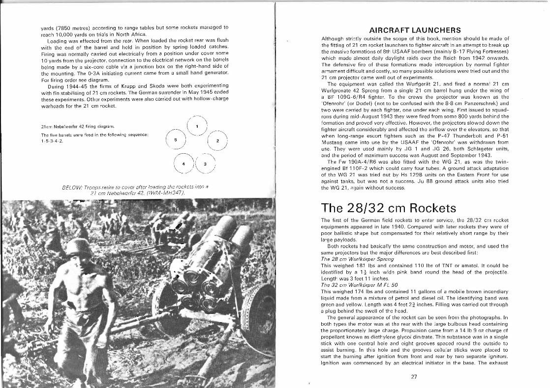
BELOW' Troops retire to cover after loading the rockets into a 21 em Nebelwerfer42. (lWM-MH347) .
AIRCRAFT LAUNCHERS Although strictly outside the scope of this book, mention should be made of the fitting of 21 cm rocket launchers to fighter aircraft in an attempt to break up the massive formations of 8th USAAF bombers (mainly B-17 Flying Fortresses) which made almost daily daylight raids over the Reich from 1942 onwards. The defensive fire of these formations made interception by normal fighter armament difficult and costly, so many possible solutions were tried out and the 21 cm projector came well out of experiments.
The equipment was called the Wurfgerat 21, and fired a normal 21 cm Wurfgrenate 42 Spreng from a single 21 cm barrel hung under the wing of a BF 109G·6/ R4 fighter. To the crews the projector was known as the 'Ofenrohr' (or Dodel) (not to be confused with the 8·8 cm Panzerschrek) and two were carried by each fighter, one under each wing. First issued to squadrons during mid-August 1943 they were fired from some 800 yards behir:d the formation and proved very effective. However, th e projectors slowed down the fighter aircraft considerably and affected th e airflow over the elevators, so that wh en long-range escort fighters such as the P-47 Thunderbolt and P-51 Mustang came into use by the USAAF the 'Ofenrohr' was withdrawn from use. They were used mainly by JG 1 and JG 26, both Schlageter units, and the period of maxim um success was August and September 1943.
The Fw 190A-4/ R6 was also fitted with the WG 21, as was the twinengined Bf 11 OF-2 which could carry four tubes . A ground attack adaptation of th e WG 21 w as tried out by Hs 129B units on the Eastern Front for use against tanks, but was not a success. Ju 88 ground attack units also tried the WG 21, ?gain without success.
The 28/32 cm Rockets The first of the Ger'man field rockets to enter service, th e 28/32 cm rccket equipments appeared in late 1940. Compared with later rockets they were of poor ballistic shape but compensated for their relatively short range by th ei r large payloads.
Both rockets had basically the same construction and motor, and used the same projectors but the major difference5 are best described first: The 28 em Wurfkdrper Spreng This weighed 181 Ibs and contained 110 Ibs of TNT or amatol. It could be identifi ed by a 1 j- inch wid ') pink band round the head of the projecti le. Length was 3 feet 11 inches. The 32 em Wurfkdrper M FL 50 This weighed 174 Ibs and co ntained 11 gallons of a mobile brown incendiary liquid made from a mi xture of petrol and diesel oil. The identifying band was green and yellow. Length was 4 feet 2~ inches. Filling was carried out through a plug behind the swell of the head .
The general appearance of the rocket can be seen from the photographs. In both types the motor was at th e rear with the la rge bulbous head containing the proportionately large charge. Propulsion came from a 14 Ib 9 oz charge of propellant known as diethylene glycol dinitrate . This substance was in a single stick with one central hole and eight grooves spaced round the outside to assist burning . In this hole and the grooves cellular sticks were placed to start the burning after ignition from front and rear by two separate ignitors. Ignition was commenced by an electrical initiator in the base . The exhaust
27
gases vented through 26 1 cm jets inclined 14 0 right to impart spin to the rocket in flight . Diameter of the motor was 14 cm. For tropical use the exhaust end of the motor was sealed with aluminium foil or a mild steel plate. 'European' rounds were left unprotected.
The fuse on the 28 cm was of the point-detonating or graze action type. A safety pin was fitted which had to be removed before firing. After firing, two centrifugal bolts armed the fuse. Fusing for the 32 cm rocket was similar.
Both types were contained in a wood or metal crate known as a 'packkiste'. They were designed to be fired from this crate and the crate also served as storage and cnrrying containers. Maximum range for the 28 cm was 2337 yards and 2217 yards for the 32 cm. Minimum range was 1019 yards.
LAUNCHERS Simplest of all of the 28/ 32 cm projectors was the carrying crate. Each crate had small hinged legs on its base and these could be used for small elevation corrections after the front of the crate had been positioned on an earth mound or low wall. Laying was completed by simply pointing the round at its target. The safety pin was then removed and the rocket fired electrically by a hand genera tor after the user had taken cover some 10-15 yards away. Single rou nds used in this way were of great assistance in demolishing strong-points and bunkers in the path of attacking infantry units but accuracy was not of a high order and only large targets could be usefully engaged. However the large explosive or incendiary charge was devastating in its effect.
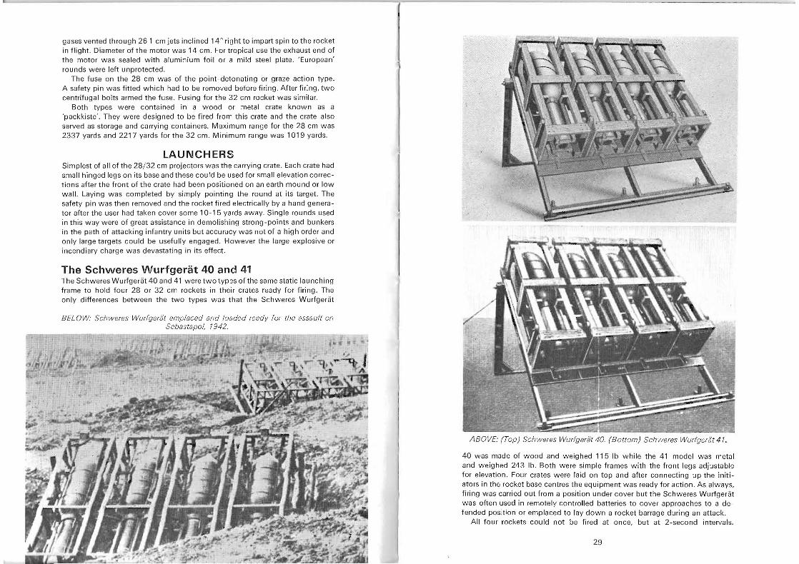
The Schweres Wurfgerat 40 and 41 The Schweres Wurfgeriit 40 and 41 w ere two tYP3S of the same static launching frame to hold four 28 or 32 cm rockets in their crates ready for firing. The only differences between the two types wns that the Schweres Wurfgeriit
BEL OW: Schweres Wurfgeriit emplaced and loaded ready for the assault on Sebastapol, 1942.
ABOVE: (Top) Schweres Wurfgerat 40. (B ottom) Schweres Wurfgeri':t 41.
40 was made of wood and weighed 115 Ib while the 41 model was metal and weighed 243 lb. Both were simple frames with the front legs adjustable for elevation. Four crates were laid on top and after connecting up the initiators in the rocket base centres the equipment was ready for action. As always, firing was carried out from a position under cover but the Schweres Wurfgeriit was often used in remotely controlled batteri es to cover approaches to a defended position or emplaced to lay down a rocket barrage during an attack .
All four rockets could not be fired at once, but at 2-second intervals.
29
This delay was introduced automatically by means of a device known as the GILikzundkette 40 mV. It was in fact made up of lengths of a delay composition in plug assemblies to each rocket. An electrical pulse from a standard hand generator fired one rocket and the delay composition then acted as a slowmatch to fire off the other rockets after 2, 4 and then 6 seconds. The cableform ends were identifiable by metal tags and labelled 4,0,2,6 (seconds) from left to right as this was the correct firing order, ie, 3-1-2-4. The required firing current was
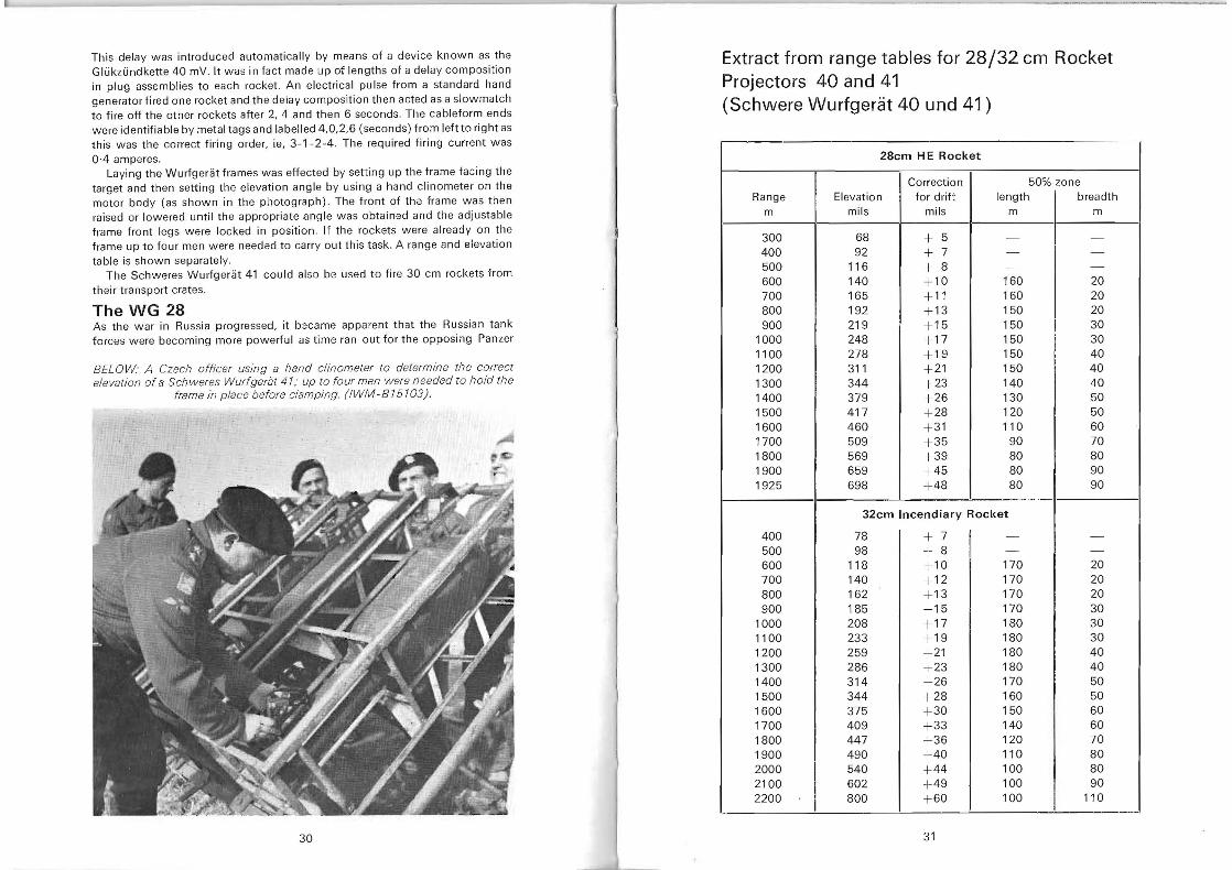
OA amperes. Laying the Wurfgeriit frames was effected by setting up the frame facing the
target and then setting the elevation angle by using a hand clinometer on the motor body (as shown in the pl1otograph). The front of the frame was then raised or lowered until the appropriate angle was obtained and the adjustable frame front legs were locked in position. If the rockets were already on the frame up to four men were needed to carry out this task. A range and elevation table is shown separately.
The Schweres Wurfgerat 41 could also be used to fire 30 cm rockets from their transport crates.
The WG 28 As the war in Russia progressed, it bacame apparent that the Russian tank forces were becoming more powerful as time ran out for the opposing Panzer
BEL OW· A Czech officer using a hand clinometer to determine the correct elevation of a Sch weres Wurfgerat 41; up to four men were n eeded to hold the
frame in place before clamping. (IWM-81 5 103).
Extract from range tables for 28/32 cm Rocket Projectors 40 and 41 (Schwere Wurfgerat 40 und 41)
28cm HE Rocket
!Correction 50% zone Range Elevation for drift length breadth
m mils mils m m
300 400 500 600 700 800 900
1000 1100 1200 1300 1400 1500 1600 1700 1800 1900 1925
68 92
116 140 165 192 219 248 278 311 344 379 417 460 509 569 659 698
+ 5 + 7 + 8 +10 + 11 + 13 + 15 + 17 + 19 +21 +23 +26 + 28 + 31 + 35 + 39 + 45 +48
- -- -
--
160 20 20160
150 20 30150
150 30 150 40
40150 140 40
50130 120 50
60110 7090
80 80 9080 9080
400 500 600 700 800 900
1000 1100 1200 1300 1400 1500 1600 1700 1800 1900 2000 2100 2200
,,,_ , ,. 0
32cm Incendiary Rocket
78 98
118 140 162 185 208 233 259 286 314 344 375 409 447 490 540 602 800
+ 7 + 8 + 10 + 12 +13 + 15 +17 + 19 + 21 + 23 + 26 +28 +30 + 33 +36 +40 + 44 +49 + 60
31
--I
--i 170 20 170 20 170 20 170 30 180 30 180 30 180 40
40180 170 50 160 50
60150 140 60
70120 110 80 100 80
90100
I 100 110
30
units. To try and stem the armoured flood, many airborne weapons were experimented with, and amongst them was a tube-launched adaptation of the 28 cm rocket. known as the Werfer Gerat 28 (or WG 28) . This launcher was mounted under the wings of both the Hs 129B and an undesignated Ju 88, unofficially known as the Ju 88N or Ju 88Nbwe. In both cases the WG 28 was not a success, probably due to its drag-inducing large frontal area and the generally poor accuracy of the 28 cm rocket. As a result of the experiments both types of aircraft were adapted to carry the 7·5 cm Kwk 39 anti-tank gun.
Another type of aircraft that attempted to use the WG 28 operationally was the Focke-Wulf F 190F-8. These aircraft were flown by ·SchlachtflieJer' units on the Eastern Front but the results were not encouraging and the units went on to try other ·tank-busting· methods. In service with these units the WG 28 was referred to as the ·Werfer-Granate 28/ 32· .
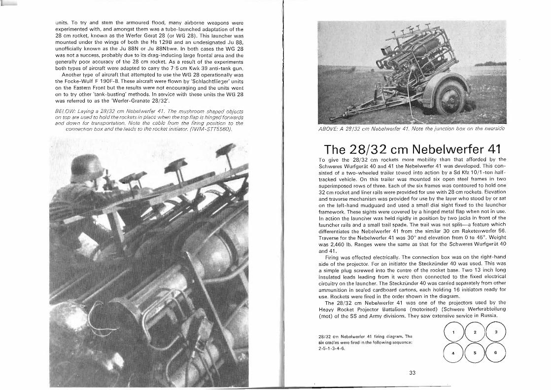
BELOW: Laying a 28/32 cm Nebelwerfer 41 . The mushroom shaped objects on top are used to hold the rockets in p lace when the top flap is hinged forwards and dow n for transportation. Note the cable from the firing position to the
connection box and the l eads to the rocket initiator. (I WM -STT5560) . ABOVE: A 28/32 cm N ebelwerfer 41. Note the junction box on the nearside
The 28/32 em Nebelwerfer 41 To give the 28/ 32 cm rockets more mobility than that afforded by the Schweres Wurfgerat 40 and 41 the Nebelwerfer 41 was developed. This consisted of a two-wheeled trailer towed into action by a Sd Kfz 1 O/1-ton halftracked vehicle. On this trailer was mounted six open steel frames in two superimposed rows of three. Each of the six frames was contoured to hold one 32 cm rocket and liner rails were provided for use with 28 cm rockets. Elevation and traverse mechanism was provided for use by the layer who stood by or sat on the left-hand mudguard and used a small dial sight fixed to the launcher framework. These sights were covered by a hinged metal flap when not in use. In action the launcher was held rigidly in position by two jacks in front of the launcher rails and a small trail spade. The trail was not split-a feature which differentiates the Nebelwerfer 41 from the similar 30 cm Raketenwerfer 56. Traverse for the Nebelwerfer 41 was 30° and elevation from 0 to 45°. Weight was 2,460 lb . Ranges were the same as that for the Schweres Wurfgerat 40 and 41.
Firing was effected electrically. The connection box was on the right-hand side of the projector. For an initiator the Steckzunder 40 was used. This was a simple plug screwed into the centre of the rocket base . Two 13 inch long insulated leads leading from it were then connected to the fixed electrical circuitry on the launcher. The Steckzunder 40 was carried separately from other ammunition in sealed cardboard cartons, each holding 16 initiators ready for use. Rockets were fired in the order shown in the diagram.
The 28/ 32 cm Nebelwerfer 41 was one of the projectors used by the Heavy Rocket Projector Battalions (motorised) (Schwere Werferabteilung (mot) of the SS and Army divisions. They saw extensive service in Russia.
28/ 32 cm Nebelwerler 41 firing diagram. The 000six crad les were fired in the follow ing sequence:
2-5-1-3-4-6. 000 33
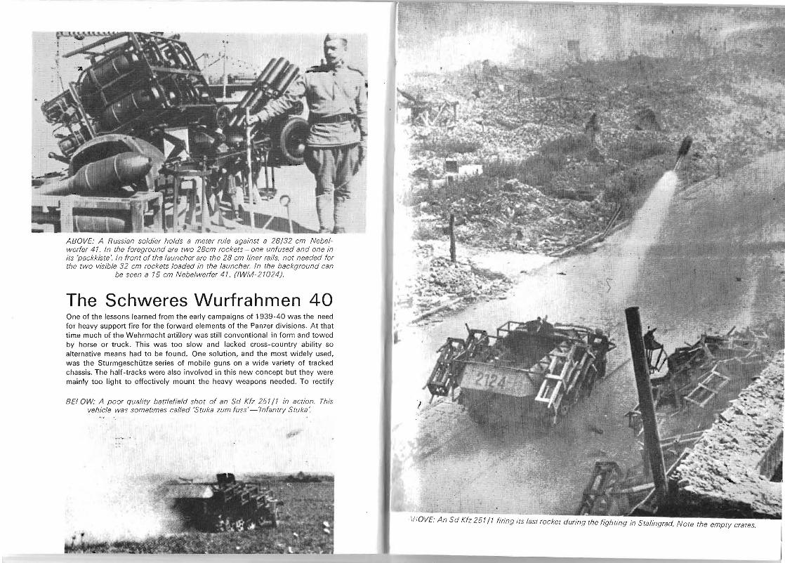
ABOVE: A Russian soldier holds a meter rule against a 28/32 cm Nebelwerfer 41. In the foreground are two 28cm rockets - one unfused and one in its 'packkiste·. In front of the launcher are the 28 cm liner rads. not needed for the two visible 32 cm rockets loaded in the launcher. In the background can
be seen a 15 cm Nebelwerfer 41. (IWM-21024J.
The Schweres Wurfrahmen 40 One of the lessons learned from the early campaigns of 1939-40 was the need for heavy support fire for the forward elements of the Panzer divisions. At that time much of the Wehrmacht artillery was still conventional in form and towed by horse or truck. This was too slow and lacked cross-country ability so alternative means had to be found. One solution, and the most widely used, was the Sturmgeschiitze series of mobile guns on a wide variety of tracked chassis. The half-tracks were also involved in this new concept but they were mainly too light to effectively mount the heavy weapons needed. To rectify
BELOW: A poor qualilV battlefield shot of an Sd Kfz 251/1 in action. This vehicle was sometimes called 'SlUka zum fuss' -'Infantrv Stuka'.
IUOVE: An Sd Kfz 251 /1 firing its last rocket during the fighting in Stalingrad. Note the empIV crates.
~ -.... - :..-.-
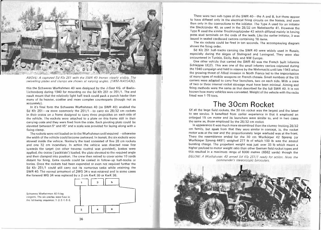
ABOVE: A captured Sd Kfz 251 with the SWR 40 frames clearly visible. The swivelling plates and clamps are shown at varying angles. (IWM -NA 10436) .
this the Schweres Wurfrahmen 40 was designed by the J.Gast KG. of BerlinLichtenberg during 1940 for mounting on the Sd Kfz 251 or 251 / 1. The end result meant that the relatively light half-track could pack a punch harder than many of its heavier, costlier and more complex counterparts (though not as accurately) .
In it's final form the Schweres Wurfrahmen 40 (or SWR 40) enabled the Sd Kfz 251-or more commonly the 251 / 1-to carry si x 28/ 32 cm rockets in their crates on a frame designed to carry three projectiles on each side of the vehicle. The rockets were attached to a plate on this frame still in their carryi ng crate and they were fired from the crate. Each pivoting plate could be elevated between 5° and 45° and a scale was provided for laying along with a fixing clamp.
The rockets were not loaded on to the Wurfrahmen until required-otherwise the width of the vehicle could become awkward. In transit, the six rockets were stowed inside the vehi c le. Normally the load consisted of five 28 cm rockets and one 32 cm incendiary. In action the vehicle was directed nose first towards the target (no other traverse control was provided), brakes were applied, the crates ('packkiste') loaded, th e plate elevated to the required angle and then clamped into position . The crew then retired to cover some 10 yards distant for firing. Extra rounds could be carried in follow- up half-tracks or lorries. Once the rockets had been expended or even not required further the Sd Kfz 251 / 1 could still carry out its numerous tasks while retaining the SWR 40. The normal armament of 2MG 34 s was retained and in some cases the forward MG 34 was replaced by a 2 cm KwK 30 or KwK 38 .
Schweres Wurfrahmen 40 firing diagram. The si x crad les w ere fired in Ihe foll owing sequence : 1-2-3- 4-5 -6.
36
There were two sub-types of the SWR 40-the A and B, but these appear to have differed only in the electrical firing circuits on the frames, and even then only in the connections to the initiator. The Type A used for an initiator the Steckzunder 40, as used in the 28/32 cm Nebelwerfer 41. However the Type B used the similar Druckknopfzunder 42 which differed mainly in having press stud terminals on the ends of th e leads. Like the earlier initiator, it was issued in sealed cardboard cartons containing 16 items.
The six rockets could be fired in ten seconds. The accompanying diagram shows the firing order.
Sd Kfz 251 half-tracks carrying the SWR 40 were widely used in Russia, especially during the sieges of Stalingrad and Leningrad. They were also encountered in Tunisia, Sicily, Italy and NW Europe.
One other vehicle that carried the SWR 40 was th e French built Infantrie Schlepper UE(f) . This was one of the small infantry carriers captured during the 1940 campaign and held in reserve by the Wehrmacht until late 1943 when the growing threat of Allied invasion in North France led to the improvisation of many types of mobile weapons on French cha ssis. Small numbers of the UE carriers were adapted to carry four launchers, two on each side. With a crew of two or three internal rocket stowage must have been minimal. Aiming and firing methods were th e same as that described for the full SWR 40. It is not known how many vehicles w ere converted . Weight of th e vehicle with the racks fitted was 1 ·75 tons.
The 30cm Rocket Of all the large field rockets, the 30 cm rocket was the largest and the latest to see service. It benefited from earlier experience in that it employed an enlarged 15 cm motor and its launchers were similar to, and in two cases the same as, those employed by the 28/ 32 cm rocket.
In appearance it was much more streamlined than the clumsy-looking 28/32 cm family, but apart from that they were similar in concept, ie, the rocket motor was at the rear and the proportionately large warhead w as at the front . There the resemblance ended for the 30 cm Wurfkiirper 42 Spreng (or Wurfkiirper Spreng 4491) weighed 277 Ib of which 100 Ib was the amatol bursting charge. The propellant weight was just over 33 Ib which meant a higher payload to motor w eight ratio than other German field rocket types and this resulted in a maximum range of 6000 metres (6562 yards) though the
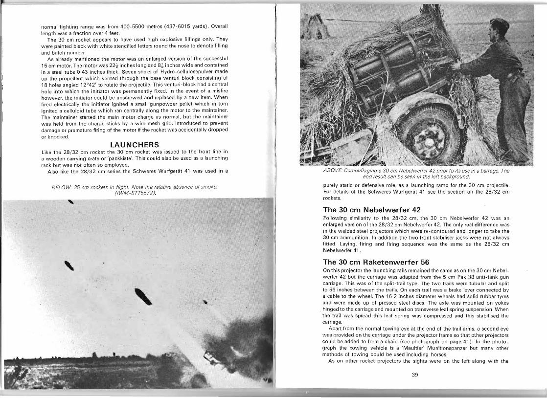
BELOW: A Wurfrahmen 40 armed Sd Kfz 251/1 ready for action. Note the commander's stereoscopic binoculars.
normal fighting range was from 400- 5500 metres (437-6015 yards) . Overall length was a fraction over 4 feet.
The 30 cm rocket appears to have used high explosive fillings only. They were painted black with white stencilled letters round the nose to denote filling and batch number.
As already mentioned the motor was an enlarged version of the successful 15 cm motor. The motor was 22-! inches long and 8-! inches wide and contained in a steel tube 0-43 inches thick. Seven sticks of Hydro-cellulosepulver made up the propellent which vented through the base venturi block consisting of 18 holes angled 12°42' to rotate the projectile. This venturi-block had a central hole into which the initiator was permanently fixed . In the event of a misfire however, the initiator could be unscrewed and replaced by a new item. When fired electrically the initiator ignited a small gunpowder pellet which in turn ignited a celluloid tube which ran centrally along the motor to the maintainer. The maintainer started the main motor charge as normal, but the maintainer was held from the charge sticks by a wire mesh grid, introduced to prevent damage or premature firing of the motor if the rocket was accidentally dropped or knocked.
LAUNCHERS Like the 28/ 32 cm rocket the 30 cm rocket was issued to the front line in a wooden carrying crate or 'packkiste'. This could also be used as a launching rack but was not often so employed.
Also like the 28/32 cm series the Schweres Wurfgerat 41 was used in a
BELOW: 30 cm rockets in flight. Note the relative absence of smoke. (IWM-STT5572J, ,
, , ,
ABOVE: Camouflaging a 30 cm Nebelwerfer 42 prior to its use in a barrage. The end result can be seen in the left background.
purely static or defensive role, as a launching ramp for the 30 cm projectile . For details of the Schweres Wurfgerat 41 see the section on the 28/ 32 cm rockets.
The 30 em Nebelwerfer 42 Following similarity to the 28/ 32 cm, the 30 cm Nebelwerfer 42 was an enlarged version of the 28/ 32 cm Nebelwerfer 42. The only real difference was in the w elded steel projectors which were re-contoured and longer to take the 30 cm ammunition . In addition the two front stabiliser jacks were not always fitted . Laying, firing and firing sequence was the same as the 28/ 32 cm Nebelwerfer 41 .
The 30 em Raketenwerfer 56 On this projector the launching rails remained the same as on the 30 cm Nebel werfer 42 but the carriage was adapted from the 5 cm Pak 38 anti-tank gun carriage. This was of the split-trail type. The two trails were tubular and split to 56 inches between the trails. On each trail was a brake lever connected by a cable to the wheel. The 16·2 inches diameter wheels had solid rubber tyres and were made up of pressed steel discs. The axle was mounted on yokes
. hinged to the carriage and mounted on transverse leaf spring suspension. When the trail was spread this leaf spring was compressed and this stabilised the carriage.
Apart from the normal towing eye at the end of the trail arms, a second eye was provided on the carriage under the projector frame so that other projectors could be added to form a chain (see photograph on page 41). In the photograph the towing vehicle is a 'Maultier' Munitionspanzer but many other methods of towing could be used including horses.
As on other rocket projectors the sights were on the left along with the
39
elevating (from 0 °_65 °) and traverse (40°) controls. However, apart from the normal dial sight an open fixed sight calibrated from 100-1000 metres (110
1093 yards) was also provided . As mentioned in the section on the 15 cm rocket the 30 cm Raketenwerfer
56 could be adapted to fire the 15 cm projectile. Liner rails could be inserted into the 30 cm projectors and when not in use, these rails were stacked and
secured onto the launcher frames (see photographs) .
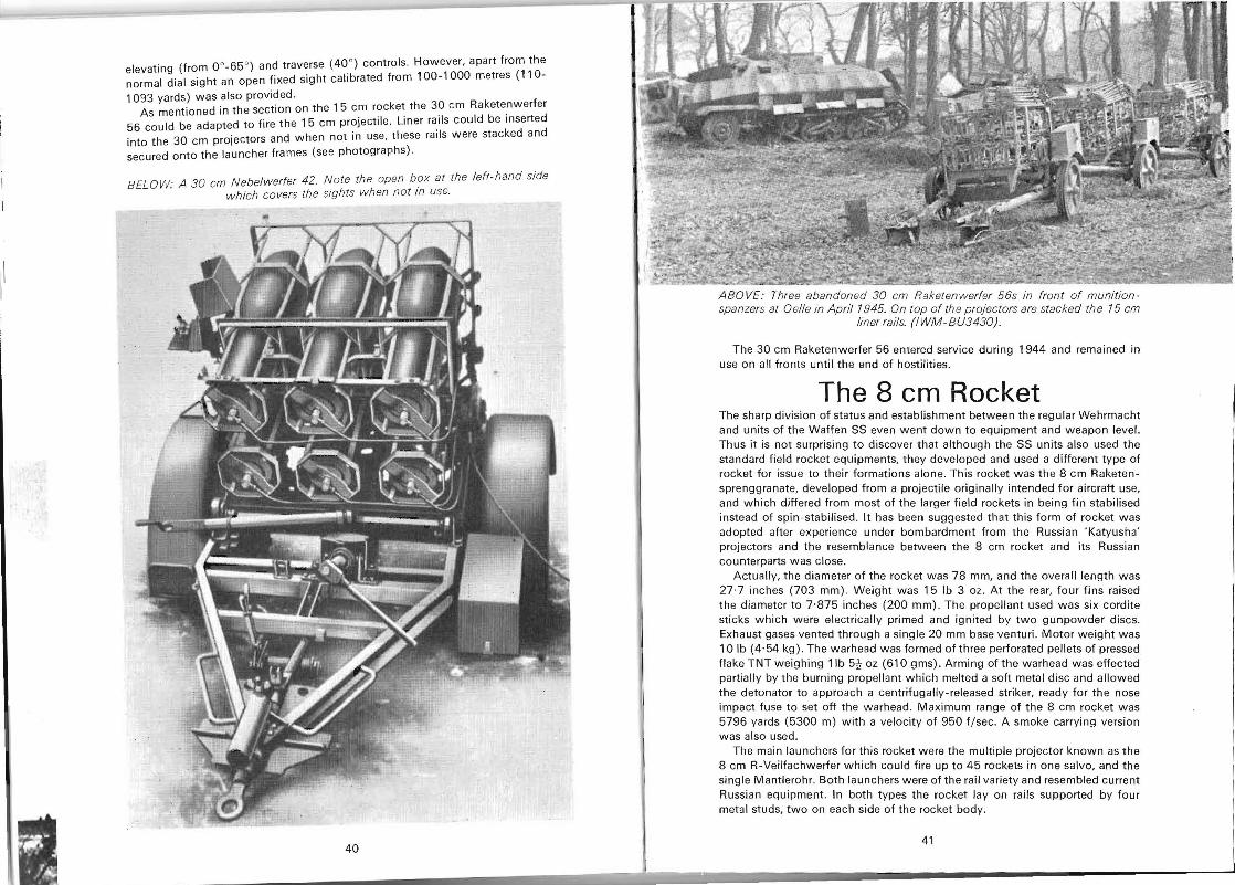
BELOW: A 30 em N ebelwerfer 42. Note the open box at the left- hand side which covers the sights when not in use.
40
ABOVE: Three abandoned 30 em Raketenwerfer 56s in front of munition spanzers al Oelle in Ap ril 1945. On top of the proj ectors are stacked the 15 em
liner rails. (I WM -BU3430) .
The 30 cm Raketenwerfer 56 entered service during 1944 and remained in use on all fronts until the end of hostilities.
The 8 cm Rocket The sharp division of status and establishment between the regular Wehrmacht and units of the Waffen 55 even went down to equipment and weapon level. Thus it is not surprising to discover that although the 55 units also used the standard field rocket equipments, they developed and used a different type of rocket for issue to their formations alone. This rocket was the 8 cm Raketensprenggranate, developed from a projectile originally intended for aircraft use, and which differed from most of the larger field rockets in being fin stabilised instead of spin-stabilised . It has been suggested that this form of rocket was adopted after experience under bombardment from the Russian 'Katyusha' projectors and the resemblance between the 8 cm rocket and its Russian counterparts was close.
Actually, the diameter of the rocket was 78 mm, and the overall length was 27· 7 inches (703 mm) . Weight was 15 Ib 3 oz . At the rear, four fins raised the diameter to 7·875 inches (200 mm) . The propellant used was six cordite sticks which were electrically primed and ignited by two gunpowder discs. Exhaust gases vented through a single 20 mm base venturi. Motor weight was 10 Ib (4 ' 54 kg). The warhead was formed of three perforated pellets of pressed flake TNT weighing 11b 5t oz (610 gms) . Arming of the warhead was effected partially by the burning propellant which melted a soh metal disc and allowed the detonator to approach a centrifugally-released striker, ready for the nose impact fuse to set off the warhead. Maximum range of the 8 cm rocket was 5796 yards (5300 m) with a velocity of 950 f/sec. A smoke carrying version was also used.
The main launchers for this rocket were the mUltiple projector known as the 8 cm R-Veilfachwerfer which could fire up to 45 rockets in one salvo, and the single Mantlerohr. Both launchers were of the rail variety and resembled current Russian equipment. In both types the rocket lay on rails supported by four metal studs, two on each side of the rocket body.
41
ABOVE: An 8 cm Raketensprenggranate. N ote the leads running from the base to the firing circuit.
The performance of the 8 cm fin-stabilised rocket in action as opposed to the more complex 'spinners' added further fuel to the arguments between the SS and the Army, and in early 1944 a meeting was held in Berlin to decide the matter. Their decision was that the 8 cm rocket was superior to the 15 cm series but Hitler himself overruled any change-over in production rates and ordered large scale field trials of the two equipments which were never completed. In retrospect it seems likely that the decision in favour of the 8 cm was largely a political one in view of the gradual and insidious policy of the SS in taking over every part of the war effort of the Third Reich-a policy which culminated in SS control of the V-weapon campaign and even eventually the
Wehrmacht itself.
The 10 em Nebelwerfer 35 and 40
The Nebelwerfer 35 and 40 are included as they constituted the first equipment of the Chemical Warfare troops. They were not rocket equipments but large
mortars. First issued to the Nebelabteilung in late 1935 the 10 cm Nebelwerfer 35
was an enlarged version of the 8 cm Schwere Granatenwerfer 34 mortar. Five men formed the crew in action and the 228 Ib weight of the complete weapon could be transported by pack-animal, two-wheeled handcart or sledge. Rate of fire was of the order of 12-15 rounds per minute. Range was 3025 m. In 1939 the Nebelwerfer 35 was the standard equipment of the Nebelabteilung during the Polish campaign and was also issued to the Gebirgswerferabteilung (mountain rocket projector brigades) .
The 10 cm Nebelwerfer 40 was a much heavier and more complex weapon . It embodied a recoil mechanism as the projectile was loaded via a breech block and fired by percussion as in a normal artillery piece--however the high elevation and trajectory of a mortar was retained, and the barrel remained smooth bored. Weight was 1730 Ib which meant that the piece had to be towed on its wheeled carriage, usually behind a light truck or by men across country. Range was increased to 6225 m and the firing rate was 8-10 rounds
per minute.
AMMUNITION The Nebelwerfer 35 and 40 both had a calibre of 10·5 cm but fired differing ammunition- however, the Nebelwerfer 35 could fire the generally heavier Nobolwerfer 40 rounds. A list of the various types follows:
42
10 em Nebelwerfer 35 HE 10 cm Wurfgranate 35 Spreng Smoke 10 cm Wurfgranate 35 Nebel
10 cm Wurfgranate 35 Nebel S Incendiary 10 cm Wurfgranate 35 Brenn
10 em Nebelwerfer 40 HE 10 cm Wurfgranate 40 Spreng Smoke 10 cm Wurfgranate 40 Nebel
10 cm Wurfgranate 40 Nebel S 10 cm Wurfgranate 40 wKh Nebel
Weights varied-for a rough guide the 35 Nebel weighed 16 Ib while the 40 Nebel weighed 21·9 lb.
Chemical-filled rounds (other than smoke) were available but not used.
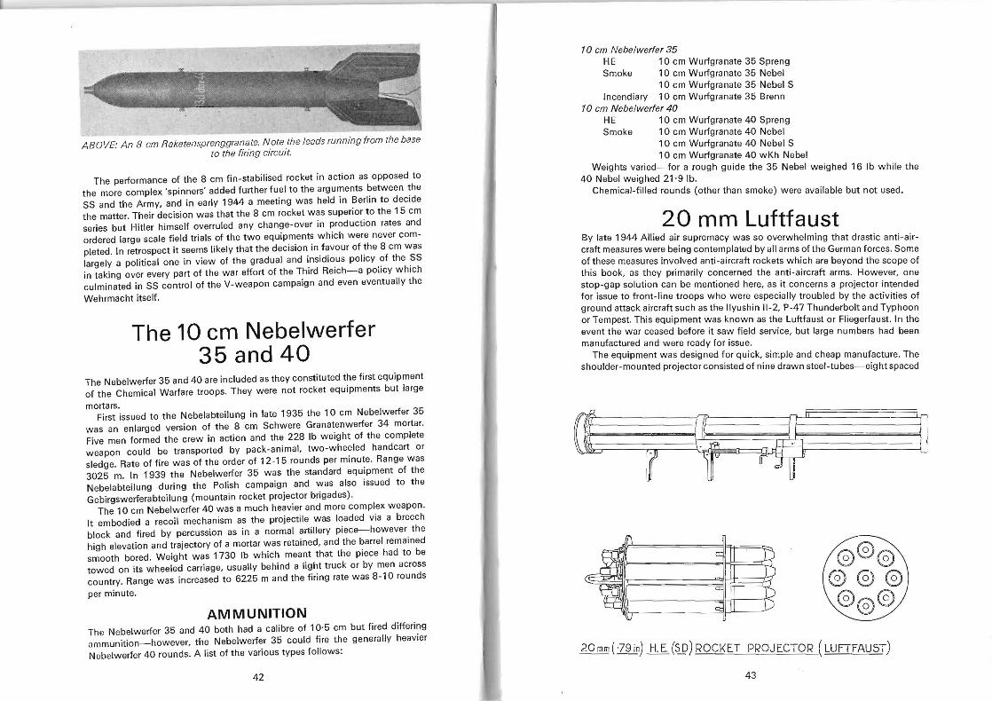
20 mm Luftfaust By late 1944 Allied air supremacy was so overwhelming that drastic anti-aircraft measures were being contemplated by all arms of the German forces. Some of these measures involved anti-aircraft rockets which are beyond the scope of this book, as they primarily concerned the anti-aircraft arms. However, one stop-gap solution can be mentioned here, as it concerns a projector intended for issue to front-line troops who were especially troubled by the activities of ground attack aircraft such as the Ilyushin 11-2, P-47 Thunderbolt and Typhoon or Tempest. This equipment iNas known as the Luftfaust or Fliegerfaust. In the event the war ceased before it saw field service, but large numbers had been manufactured and were ready for issue.
The equipment was designed for quick, simple and cheap manufacture. The shoulder-mounted projector consisted of nine drawn steel-tubes-eight spaced
@®@ @@@ @@@
20 mm (-79 in) H. E. (~) ROCKET PROJECTOR (LUFTFAU5T)
43
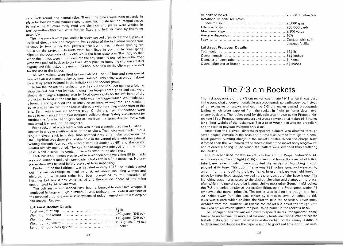
In a circle round one central tube. These nine tubes were held securely in place by four identical stamped steel plates. Each plate had an integral sleeve to make the structure really rigid and the two end plates were welded in position- the other two were friction fitted and held in place by the firing
assembly. The nine rounds were pre-loaded in ready-spaced clips 50 that the clip could
be fitted directly into the projector. Pre-spacing of the individual rounds was effected by two further steel plates similar but lighter, to those spacing the tubes on the projector. Rounds were held fixed in position by wire spring clips on the base plate of the clip while the front plate was 'floating', so that when the rounds were introduced into the projector and pushed home the front plate was pushed back onto the base. After pushing home the clip was rotated slightly and this locked the unit in position. A handle on the clip was provided
for the use of the loader. The nine rockets were fired in two batches-one of four and then one of
five with an 0·2 second delay between salvoes. This delay was brought about by a delay pellet inserted in the initiators of the second group.
To fire the rockets the projector was held on the shoulder against a folding shoulder-rest and held by two folding hand-grips (both grips and rest were simple stampings) . Sighting was by fixed open sights on the left-hand of the projector. In front of the rear hand-grip was the trigger which when released allowed a spring-loaded rod to energize an impulse magneto. The resultant pulse was transmitted to the rocket clip by a wire via a plug connection to the clip. Earth return was via another plug. On the clip itself connections were made to each rocket from two insulated collector rings. Safety was effected by turning the forward hand-grip out of line from the spring-loaded rod which
prevented it energizing the magneto. Each rocket had a warhead which was in fact a standard 20 mm HE shell
already in wide use with all arms of the services. The motor was made up of a single diglycol stick in a steel tube crimped onto an annular groove on the shell. Ignition was through a central hole in the venturi plate with the exhaust venting through four equally spaced venturis angled at 45 ° and the central venturi already mentioned. The igniter cartridge was crimped onto the motor base. A self -destructing contact fuse was fitted to the shell nose.
Each basic equipment was issued in a wooden crate weighing 95 lb. Inside was one launcher and eight pre-loaded clips each in a fibre container. No pre
II' preparation was needed before use apart from unpacking . Production of the Luftfaust was initiated in early 1945 and mainly carried
out in small workshops manned by unskilled labour, including women and children . Some 10,000 units had been completed by the cessation of hostilites but few if any were issued and there is no record of any being
encountered by Allied aircrews. The Luftfaust would indeed have been a formidable defensive weapon if
employed in large enough numbers. It was probably the earliest ancestor of the personal ground-to-air missile systems of today- one of which is Blowpipe
and another Redeye.
Luftfaust Rocket Details Total weight of clip .... .... ........ .. .. .. .. .... .... .. ...... .. 5t Ib Weight of one round .. .... .... .............. .. .. .. ... .250 grams (8'8 oz) Weight of shell ..... ... ....... .. .... . ...... ... .. .. ........... .. 110 grams (3 '9 oz) Weight of propellant.. .. . .. .. .. .. .. ........ .. .. .... .40·7 grams (1 -4 oz) Length of round less igniter ......... .. ............. .... ..... 9 inches
44
Velocity of rocket .. . . . . . . . . .... . .. . ..... . . .... ..... .. ........ 280-310 metres/sec Rotational velocity 40 metres
from muzzle . . ..... .... .. ............... ..... ...... 26,000 rpm Effective range ..... ...... . .. .................. .. .......... .... 230-550 yards Maximum range .. ... . . .. .. ..... . .. ...... .... ... .. . . ............ 2,200 yards Average dispersion ....... . ... . . . . .• .. . . ...... . . . . ... ... . . ... 10% Fuse . ............ . ..... ... ...... .. ...... . ... .. .... .. ....... . ... .Contact with self
destruct facility. Luftfaust Projector Details Total weight .... .. ..... .... .... . .... ...... ............14tlb Overall length ...... .. ............ . .... .. .. . ......... .... .... 51 t inches Diameter of each tube .. .. . ..... .. .... .. . .. .. .. i inches Overall diameter at breech ..... .. .. .. .. .... . .. . .. . ... ......... 5j inches
The 7· 3 cm Rockets The first appearance of the 7 '3 cm rocket was in late 1941 when it was used in the somewhat unconventional role as a propaganda spreading device. Instead of an explosive or smoke warhead the 7·3 cm rocket carried propaganda leaflets which were expelled from the rocket in flight to flutter down over enemy positions. The rocket used for this role was known as the Propagandagranate 41 (or Propagandageschoss) and was a conventional rocket 16·1 inches long. Total weight of the rocket was 7 Ib 2 oz of which 1 Ib was the propellant and the leaflet payload weighed only 8 oz.
After firing the diglycol dinitrate propellant exhaust was directed through seven angled venturis in the base and a time fuse burned through to a small black powder bursting charge in the rocket's centre. When the charge burst it forced apart the two halves of the forward half of the rocket body lengthways and released a spring round which the leaflets were wrapped thus scattering the leaflets.
The launcher used for this rocket was the 7'3 cm Propagandawerfer 41, which was a simple and light (25 Ib) single-round frame. It consisted of a steel tube base-frame on which was mounted the angle -iron launching trough, pivoted at its base. This trough frame was 29~ inches long, and elevated by an arm from the trough to the base-frame. In use the base was held firmly in place by three fixed spades welded to the underside of the base frame. The launching trough was raised to the desired elevation and clamped into place, after which the rocket could be loaded. Unlike most other German field rockets the 7'3 cm series employed percussion firing, so the Propagandawerfer 41 employed the mortar principle. The rocket was laid on the trough and held 20 inches away from the base striker by a release lever. Attached to this lever was a cord which enabled the firer to take the necessary cover some distance from the launcher. On release the rocket slid down the trough ont" the fixed striker which ignited the percussion primer in the rocket's base.
The Propagandawerfer was employed by special units (Propagandatruppen) trained to undermine the morale of the enemy front-line troops. What effect the leaflets distributed by such an expensive device had on the enemy is difficult to determine but doubtless the paper was put to good and time-honoured uses.
45
THE 7·3 em MULTIPLE LAUNCHERS The development of the 7·3 cm rocket for propaganda purposes alone made for rather an expensive exercise at a time when Germany's limited resources were feeling the strain of producing large amounts of war material so it is not surprising that the 7 ·3 cm motor was adapted to carry a more offensive warhead. In this form it was renamed the 7·3 cm Raketensprenggranate and utilised mainly as an anti-aircraft weapon. However it was also used against ground targets and thus comes into the scope of this book.
The 7·3 cm R Sprgr weighed 6 Ib (2'74 kg) and was 11 ,09 inches (28'2 cm) long . Of this length the motor made up 5 3
92 inches and as
before the propellant was a one-piece charge weighing just over 1 Ib and venting through seven base venturii. The 0·62 Ib (280 grams) bursting charge in the warhead was made up of two possible fillings. One filling, coded '95'on the casing was known as 'cyclonite/TNT (60/40)'. A later variant of this was coded 'H5+Fp02' and made up of 55% cyclonite, 40% TNT and 5% wax (cyclonite is a form of RDX) . As the rocket was primarily intended as an antiaircraft weapon it carried a self destructing charge in the nose fired by a ~ inch long tracer chain ignited from a relay in the warhead base. This relay was set off by the rocket igniter. Normally the warhead was set off by a point detonating nose fuse known as the Raketenaufschlagzunder 51 (RAZ 51) which was adapted from the fuse used in standard 20 mm ammunition , The unpainted rockets were finished in a matt dark grey or black anti-corrosion coating. A 1 inch wide yellow band was painted round the rocket body and on the warhead was painted a large white 'R' and charge details, also in white.
The main launcher for this rocket was the Fohn Geriit, which could be either mobile or fixed. It consisted of 35 31 inch long launching rails mounted in a box formation of seven superimposed rows of five. As was to be expected of an anti-aircraft weapon 360° traverse was provided and elevation was from -10° to 90°. Sighting was carried out from an armoured box, fitted with a transparent plastic window, mounted to the left of the racks. The sights themselves were designed for both anti-aircraft and ground target use and a rudimentary rear and foresight was provided for rapid pointing . All thirty-five rockets were fired in one salvo, provided the two safety devices were cleared, by firing pins behind each rail.
The mobile version of the Fohn Geriit was mounted on an adapted 3·7 cm anti-aircraft gun two-wheeled trailer. Fixed mounts were set up on sheet iron or concrete platforms. Some of these mountings were used to cover river crossings at Satzvoy, Unkel and Hahn,
At the time of the German collapse development work was being carried out on 3-,5-,7- and 24-barrel projectors for the 7·3 cm rocket . Each barrel was hexagonal so various barrel combinations could be easily assembled. For the 3-,5- and 7-barrellaunchers the barrel length was 100 cm (39'37 inches) while the 24-barrel version was to be 55 cm (21'65 inches) long. Each barrel held three guide rails and spring clips held the rocket in position 20 cm from the rear. On the 24-barrel version the barrels were open leaving only the rail 'skeleton' along most of its length. Apparently the 3-barrel weapon was intended for one-man use and a 50 x 50 cm shield was provided for firer
protection . One further launcher remains to be mentioned. This is the unusual device
referred to in Allied Intelligence reports as the 7·5 cm Multiple Fortress Rocket Projector. It consisted of four rows of seven barrels mounted on a low, twowheeled trailer. The four rows were at slightly different elevations to give a
46
wide rocket dispersal and thus cover a very wide area. Each row could be individually cocked and all rows fired together. Limited elevation controls were provided.
It seems extremely likely that this device used the 7·3 cm rocket, and that this form of projector was in fact a 'one-off' device or even a field 'lash-up', as it appears that only one was ever captured and no mention of it appears in German accounts.
The 8-8 cm Rocket Grenades During the latter months of 1943 a new weapon appeared almost simultaneously on both sides of the conflict. On the American side the new weapon was known as the Launcher, Rocket, M1 and fired a small rocket 2·36 inch in diameter. The German equivalent fired a 8 ·8 cm rocket and was known as the 8·8 cm Raketenpanzerbuchse, Both of these relatively light rocket grenades could knock out any tank then in service-provided it was close enough, for both weapons could fire their missiles effectively up to only just over 100 yards, However the destructive power of the warheads owed less to their impact and explosive powers than to the nature of the warhead which was a 'shaped charge' employing the 'Munroe effect'.
This 'Munroe effect' was discovered by an American explosives expert, Professor Charles E. Munroe, as far back as 1887. Very basically a hole could be blown, or more accurately burned, through armour plate by having an air gap between a bursting charge and the plate at the time of the explosion, The bursting charge is held contained in a steel casing with the front only lightly covered with thin sheet steel. An air gap is deliberately formed by making a conical depression in the explosive and the nose is tapered only for streamlining and holding the impact fuse at the correct distance from the charge. The fuse when firing thus ignites the charge which is then 'focused' forward and spends all its destructive energy on the impact region. In practice this meant that early rocket grenades could burn a hole in up to 8?, inches of armour plate.
Despite the Munroe effect being widely known little use was made of it before World War 2. The German firm of Westfalisch-Anhaltische Sprengstoff Aktiengesellschaft did some research on shaped charges and developed them for mining purposes from 1912 onwards. Military uses were not investigated deeply until early in World War 2 when the destructive effect was enhanced by lining the shaped charge with thin sheet steel to be carried along in a vaporised state by the force of the explosion , This vapour added to the burning effect. Other metals can be used for this liner, examples being zinc and lead, and as some metals give better results than others much experimentation was carried out with various alloys. For maximum effect the charge must go off at an optimum distance from the plate so the shaped charge is not often used on high velocity projectiles but on relatively slow moving ones or fixed mines or charges. Thus the rocket was selected for use against tanks and the 'bazooka' launcher developed. It is interesting to note that the British also developed a spaced charge missile but chose to fire it from the PlAT launcher which was a spigot mortar.
In time the Munroe effect became known as the 'Hollow Charge' effect.
47
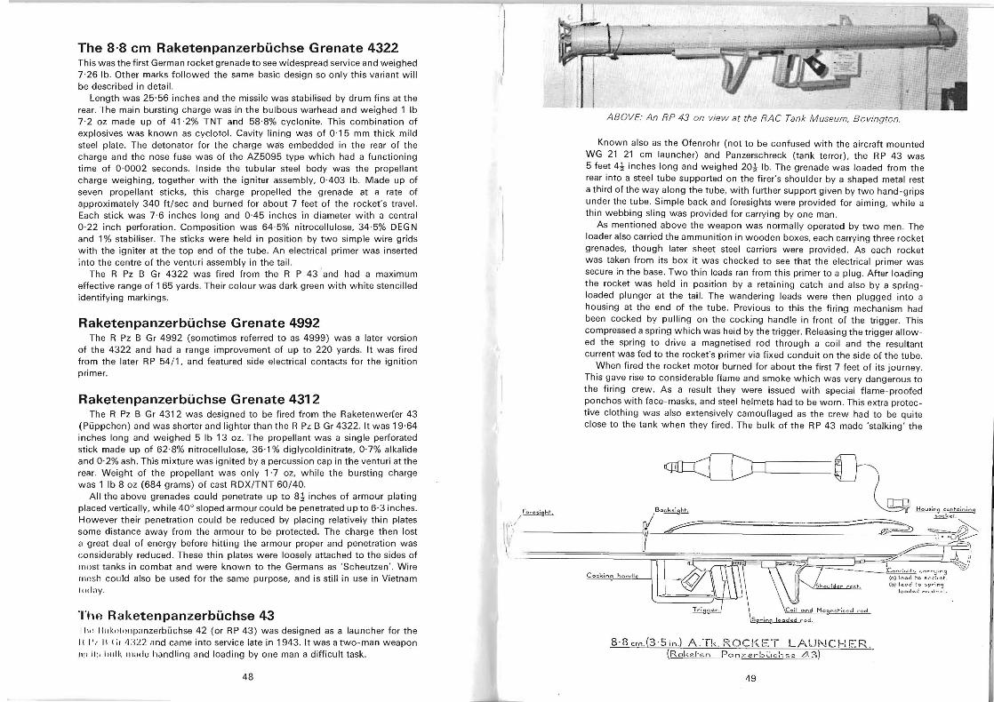
The 8·8 em Raketenpanzerbuehse Grenate 4322 This was the first German rocket grenade to see widespread service and weighed 7 ·26 lb. Other marks followed the same basic design so only this variant will be described in detail.
Length was 25·56 inches and the missile was stabilised by drum fins at the rear. The main bursting charge was in the bulbous warhead and weighed 1 Ib 7·2 oz made up of 41 ·2% TNT and 58·8% cyclonite. This combination of explosives was known as cyclotol. Cavity lining was of 0 ·15 mm thick mild steel plate. The detonator for the charge wa's embedded in the rear of the charge and the nose fuse was of the AZ5095 type which had a functioning time of 0 ·0002 seconds. Inside the tubular steel body was the propellant charge weighing, togeth er with the igniter assembly, 0-403 lb. Made up of seven propellant sticks, this charge propelled the grenade at a rate of approximately 340 ft / sec and burned for about 7 feet of the rocket's travel. Each stick was 7·6 inches long and 0-45 inches in diameter with a central 0 ·22 inch perforation. Composition was 64 ·5% nitrocellulose, 34·5% DEG N and 1 % stabiliser. The sticks were held in position by two simple wire grids with the igniter at the top end of the tube. An electrical primer was inserted into the centre of the venturi assembly in the tail.
The R pz B Gr 4322 was fired from the R P 43 ' and had a maximum effective range of 165 yards. Their colour was dark green with white stencilled identifying markings.
Raketenpanzerbuehse Grenate 4992 The R pz B Gr 4992 (sometimes referred to as 4999) was a later version
of the 4322 and had a range improvement of up to 220 yards. It was fired from the later R P 54/1, and featured side el ectrical contacts for the ignition primer.
Raketenpanzerbuehse Grenate 4312 The R pz B Gr 4312 was designed to be fired from the Raketenwerfer 43
(Pi.ippchen) and was shorter and lighter than the R pz B Gr 4322. It was 19·64 inches long and weighed 5 Ib 13 oz. The propellant was a single perforated stick made up of 62·8% nitrocellulose, 36·1 % diglycoldinitrate, 0·7% alkalide and 0·2% ash . This mixture was ignited by a percussion cap in the venturi at the rear. Weight of the propellant was only 1·7 oz, while the bursting charge was 1 Ib 8 oz (684 grams) of cast RDX/ TNT 60/ 40.
All the above grenades could penetrate up to 8~ inches of armour plating placed vertically , while 40 0 sloped armour could be penetrated up to 6·3 inches. However their penetration could be reduced by placing relatively thin plates some distance away from the armour to be protected. The charge then lost a great deal of energy before hitting the armour proper and penetration was \1;/
\,considerably reduced. These thin plates were loosely attached to the sides of most tanks in combat and were known to the Germans as 'Scheutzen' . Wire 1O(!sh could also be used for the same purpose, and is still in use in Vietnam ,,,day.
Thp, Raketenpanzerbuehse 43 III" 1I IIkoiollpanzerbuchse 42 (or RP 43) was designed as a launcher for the II I' .. II ( it II :Q 2 and came into service late in 1943. It was a two-man weapon fl li Ii :, (,,,11\ Illudu handling and loading by one man a difficult task.
ABOVE: An RP 43 on view at the RAe Tank Museum. Bovington.
Known also as the Ofenrohr (not to be confused with the aircraft mounted WG 21 21 cm launcher) and Panzerschreck (tank terror) , the RP 43 was 5 feet 4~ inches long and weighed 20~ lb. The grenade was loaded from the rear into a steel tube supported on the f irer's shoulder by a shaped metal rest a third of the way along the tube, with further support given by two hand-grips under the tube. Simple back and foresights were provided for aiming , while a thin webbing sling was provided for carrying by one man.
As mentioned above the weapon was normally operated by two men. The loader also carried the ammunition in wooden boxes, each carrying three rocket grenades, though later sheet steel carriers were provided. As each rocket was taken from its box it was checked to see that the electrical primer was secure in the base. Two thin leads ran from this primer to a plug . After loading the rocket was held in position by a retaining catch and also by a springloaded plunger at the tail. The wandering leads were then plugged into a housing at the end of the tube. Previous to this the firing mechanism had been cocked by pulling on the cocking handle in front of the trigger. This compressed a spring which was held by the trigger. Releasing the trigger allow ed the spring to drive a magnetised rod through a coil and the resultant current was fed to the rocket's primer via fixed conduit on the side of the tube .
When fired the rocket motor burned for about the first 7 feet of its journey. This gave rise to considerable flame and smoke which was very dangerous to the firing crew. As a result they were issued with special flame-proofed ponchos with face-masks, and steel helmets had to be worn. This extra protective clothing was also extensively camouflaged as the crew had to be quite close to the tank when they fired. The bulk of the RP 43 made 'stalking' the
~~
Co."" ,,~ ~@" ,Conr.u;" ~-"..,II((L / . I '" I- '. III 0/\\1\\ \ \\ (0 ) l eod ..... cCI .... r ';j; n s '§)~",~
{b} l e ad ~o scd~e t-. lo o dcdo c:~:::~~.
8·8 cm.(3 ·S in.) A.Tk. ROC !<'ET LAUNCH ER (R Clk ehzn Pan .i:erb ~,c:~ s e L'!.3)
49 48
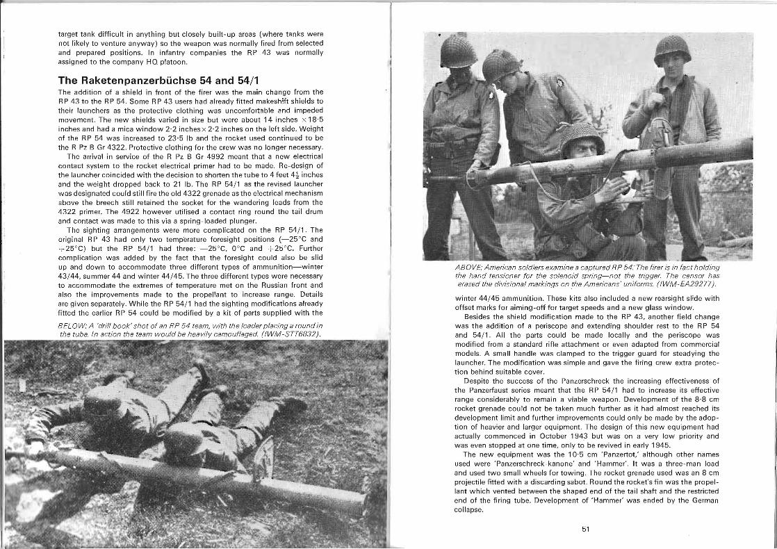
target tank difficult in anything but closely built-up areas (where tanks were not likely to venture anyway) so the weapon was normally fired from selected and prepared positions. In infantry companies the RP 43 was normally assigned to the company HQ platoon.
The Raketenpanzerbi.ichse 54 and 54/1 The addition of a shield in front of the firer was the main change from the R P 43 to the R P 54. Some R P 43 users had already fitted makeshift shields to their launchers as the protective clothing was uncomfortable 2nd impeded movement. The new shields varied in size but were about 14 inches x 18·5 inches and had a mica window 2·2 inches x 2·2 inches on the left side. Weight of the R P 54 was increased to 23'5 Ib and the rocket used continued to be the R pz B Gr 4322. Protective clothing for the crew was no longer necessary.
The arrival in service of the R pz B Gr 4992 meant that a new electrical contact system to the rocket electrical primer had to be made. Re-design of the launcher coincided with the decision to shorten the tube to 4 feet 4~ inches and the weight dropped b3ck to 21 lb . The R P 54/ 1 as the revised launcher was designated could still fire the old 4322 grenade as the electrical mechanism above the breech still retained the socket for the wandering leads from the 4322 primer. The 4922 however utilised a contact ring round the tail drum and contact was made to this via a spring-loaded plunger.
The sighting arrangements were more complicated on the RP 54/1. The original R P 43 had only two temperature foresight positions (-25°e and + 25°e) but the RP 54/1 had three : -25°e, o oe and + 25°e . Further complication was added by the fact that the foresight could also be slid up and down to accommodate three different types of ammunition-winter 43/ 44, summer 44 and winter 44/ 45. The three different types were necessary to accommodate the extremes of temperature met on the Russian front and also the improvements made to the propellant to increase range. Details are given separately. While the RP 54/1 had the sighting modifications already fitted the earlier RP 54 could be modified by a kit of parts supplied with the
BELOW: A 'drill book' shot of an RP 54 team, with the loader placing a round in the tube. In action the team would be heavily camouflaged. (IWM-STT6832).
~9 E·~'1iI
ABOVE: American soldiers examine a captured R P 54.' The firer is in fac t holding the hand tensioner for the solenoid spring-not the trigger. The censor has erased the divisional markings on the Americans' uniforms. (I WM -EA29277) .
winter 44/45 ammunition. These kits also included a new rearsight slide with offset marks for aiming-off for target speeds and a new glass window.
Besides the shield modification made to the RP 43, another field change was the addition of a periscope and extending shoulder rest to the R P 54 and 54/ 1. All the parts could be made locally and the periscope was modified from a standard rifle attachment or even adapted from commercial models. A small handle was clamped to the trigger guard for steadying the launcher. The modification was simple and gave the firing crew extra protec tion behind suitable cover.
Despite the success of the Panzerschreck the increasing effectiveness of the Panzerfaust series meant that the RP 54/1 had to increase its effective range considerably to remain a viable weapon . Development of the 8 ·8 cm rocket grenade could not be taken much further as it had almost reached its development limit and further improvements could only be made by the adoption of heavier and larger equipment. The design of this new equipment had actually commenced in October 1943 but was on a very low priority and was even stopped at one time, only to be revived in early 1945.
The new equipment was the 10·5 cm 'Panzertot: although other names used were 'Panzerschreck-kanone' and 'Hammer'. It was a three-man load and used two small wheels for towing. The rocket grenade used was an 8 cm projectile fitted with a discarding sabot. Round the rocket's fin was the propellant which vented between the shaped end of the tail shaft and the restricted end of the firing tube. Development of 'Hammer' was ended by the German collapse.
51
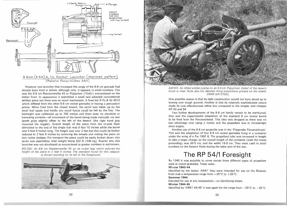
Backsi")h_t __
-c:::::===~~~
+ PlungEr
CIRCUIT OIAGAAM FOA NEW BOMB (.;;tr.d
...... il"h rinq cont~ct)
r;n<3 "'contact
8'8cm (3'5in) A. Tk. Rocker L2.unch~r (improvEd parrern) (Ra.kskn P2.n7,erbuchs~ 54/1)
However one launcher that increased the range of the 8·8 cm grenade had already been tried in action, although only, it appears, in small numbers. This was the 8·8 cm Raketenwerfer 43 or Puppchen ('Dolly') encountered on the Italian front . In appearance it resembled a small two-wheeled conventional artillery piece but there was no recoil mechanism. It fired the R pz B Gr 4312 which differed from the other 8·8 cm rocket grenades in having a percussion primer. When fired from the closed breech, the recoil was taken up by the small trail spade and hardly any recoil forces could be felt by the firer. The backsight was calibrated up to 700 metres and there were no elevation or traversing controls-all movement of the barrel being made manually via two spade grips slightly offset to the left of the breech (the right hand grip mounted the trigger). Overall length of the piece from the muzzle flash eliminator to the end of the single trail was 9 feet 10 inches while the barrel was 5 feet 9 inches long. The height was only 3 feet but this could be further reduced to 2 feet 6 inches by removing the wheels and resting the piece on two rocker sledges. For transport the piece could be easily broken down into seven sub-assemblies, total weight being 322 Ib (146 kg) . Exactly why this launcher was not developed or encountered in greater numbers is not known.
BELOW: An 8.8 cm Raketenwerfer 43 on its rocker legs which reduced the height of the piece to 2 feet 6 inches. The standard round for this weapon
is shown standing on its tail in the foreground.
52
ABOVE: An Allied soldier posing on an 8·8 cm Piippchen. Detat! of the breech block is clear. Note also the detailed firing instructions printed on the shield.
(IWM-NA 15782).
One possible reason is that its light construction would not have stood up to towing over rough ground. Another is that its relatively sophisticated nature made its cost-effectiveness rather low compared to the simpler and cheaper RP 43 and 54.
Two further developments of the 8·8 cm family remain to be mentioned. One was the experimental adaptation of the standard 8 cm mortar bomb to be fired from the Panzerschreck. This idea was dropped as there was no real advantage over using a mortar and the propellant was in increasingly short supply.
Another use of the 8·8 cm projectile was in the ' Fliegender Panzerschreck'. This was the adaptation of four 8·8 cm rocket grenades hung in a container under the wing of a Fw 190F-8. The propellant tube was increased in length to take a larger charge, so the overall length of the container (with the noses protruding) was 99·5 cm, and the width 18·8 cm. They were used in small numbers on the Eastern Front during the latter part of the war.
The RP 54/1 Foresight By 1945 it was possible to come across three different types of propellant used in rocket grenades. These were: Wi nter 1943-44 Identified by the letters 'AR KT' they were intended for use on the Russian front over a temperature range from -25°C to + 25 °C. Summer 1944. Intended for use at any temperature-no identifying letters. Wi nter 1944-45 Identified by 'ARKT 44/ 45' it was again for the range from - 25 °C to + 25 ' C.
53
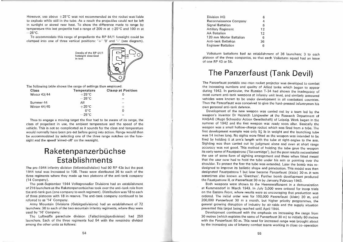
However, use above +25°C was not recommended as the rocket was liable to explode while stili in the tube . As a result the projectiles could not be left in sunlight or stored near heat. To show the difference made to range by temperature this last projectile had a range of 200 m at +25°C and 100 m at - 25°C.
To accommodate this range of propellants the RP 54/ 1 foresight could be clamped into one of three vertical positions : '+' '0' and' -' (see diagram).
» ................
Details of the RP 54/ 1 foresight described in text.
The following table shows the range of settings then employed. Class Temperature Clamp at Position Winter 43/44 +25°C 0
-25°C Summer 44 All Winter 44/ 45 +25°C +
O°C o -25°C
Thus to engage a moving target the firer had to be aware of its range, the class of propellant in use, the ambient temperature and the speed of the vehicle. This is not so complicated as it sounds for the class and temperature would normally have been pre-set before going into action. Range would then be accommodated by selecting one of the three range notches on the foresight and the speed 'aimed-off' on the rearsight.
Raketenpanzerbuchse Establishments
The pre-1944 infantry division (Infantriedivision) had 90 R P 43s but the post 1944 total was increased to 108. These were distributed 36 to each of the three regiments where they made up two platoons of the anti-tank company (14 Company) .
The post-September 1944 Volksgrenadier Divisions had an establishment of 216 launchers as the Raketenpanzerbuchse took over the anti-tank role from the anti-tank gun (one company to each regiment). Distribution was 18 to each of three platoons with 18 in reserve. The anti-tank company continued to be referred to as '14' Company.
Army Mountain Divisions (Gebirgsdivisions) had an establishment of 72 launchers: 36 to each of the two mountain infantry regiments, where they were used by '16' Company.
The Luftwaffe parachute division (Fallschirmjagerdivision) had 250 launchers. Each of the three regiments had 54 with the remainder divided among the other units as follows:
54
Division HQ 6 Reconnaissance Company 4 Signal Battalion 6 Artillery Regiment 12 AA Battalion 12 120 mm Mortar Battalion 6 Anti-tank Battalion 36 Engineer Battalion 6
Volksturm battalions had an establishment of 36 launchers; 3 to each platoon of the three companies, so that each Volksturm squad had an issue of one RP 43 or 54.
The Panzerfaust (Tank Devil) The Panzerfaust portable one-man rocket projector was developed to combat the increasing numbers and quality of Allied tanks which began to appear during 1942. In particular, the Russian T-34 had shown the inadequacy of most current anti-tank weapons at infantry unit level, and similarly armoured vehicles were known to be under development in all combatant countries. Thus the Panzerfaust was conceived to give the hard-pressed infantryman his own personal anti-tank defence.
Development of the new weapon was carried out by a team led by the weapon 's inventor Dr Heinrich Langweiler at the Research Department of HASAG (Hugo Schneider Action Geselischaft) of Leipzig . Work began in the summer of 1942 and the first weapon wa~ ready soon after. Basically the weapon was a small hollow-charge rocket which was fired from a tube. The first development example was only 5~ Ib in weight and the launching tube was 14 inches long. No sights were fitted as the weapon was intended to be fired by holding it at arm's length with the tube at right-angles to the arm. Sighting was then carried out by judgment alone and even at short range accuracy was not good. This method of holding the tube gave the weapon its early name of Faustpatrone ('fist cartridge'), but the poor results necessitated the use of some form of sighting arrangement and these when fitted meant that the user now had to hold the tube under his arm or pointing over the shoulder. To protect the firer the tube was extended. Later the bomb was redesigned to improve its ballistic shape and penetration. This model was then designated Faustpatrone 1 but later became Panzerfaust (klein) 30 m. It was sometimes also known as 'Gretchen'. Further bomb development produced the Faustpatrone II, or Panzerfaust 30 m by January/February 1943.
Both weapons were shown to the Heereswaffenamt in a demonstration at Kummersdorf in March 1943. In July 3,000 were ordered for troop trials on the Eastern Front. where results were so encouraging that production was ordered. The initial order was for 100,000 Panzerfaust (klein) 30 m, and 200,000 Panzerfaust 30 m a month, but higher priority programmes, the general growing disruption of industry by air-raids and the supply situation prevented this target being reached until April 1944.
Development continued with the emphasis on increasing the range from 30 metres (which explains the name of Panzerfaust 30 m) to initially 60 metres with the Panzerfaust 60 m. This need for increased range was brought about by the increasing use of infantry combat teams working in close co-operation
55
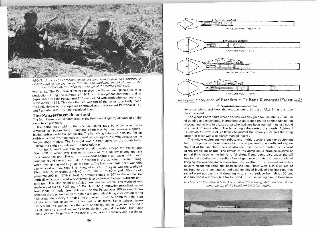
I
PANZE:RFAUST
ABOVE: A typical Panzerfaust team position, well dug-in and covering a roadway out of the picture to the left. The particular model shown is the
Panzerfaust 30 m, which had a range of 30 metres (100 yds).
with tanks. The Panzerfaust 60 m replaced the Panzerfa ust (klein) 30 m in production during the summer of 1944 but development continued and in September 1944 the Panzerfaust 1 00 m appeared with production commencing in November 1944. This was the last w eapon of the series to actually reach the field. However, development continued and the resultant Panzerfaust 150
and Panzerfaust 250 will be desc ribed later.
The Panzerfaust described The four Panzerfaust variants used in the field (see diagram) all worked on the
same basic principle . The bomb was held in the steel launching tube by a pin which was
removed just before firing . Firing the bomb was by percussion of a springloaded striker on to the propellant. The launching tube also held the flip -up sights wh ich w ere rudimentary and marked off roughly in luminous steps on the longer-range models . The foresight was a small spike on the bomb body.
Raising the sight also released the fuse safety pin . Th e bomb used was the same on all models except the Panzerfaust
(klein) 30 m which was smaller. It consisted of a hollow-charge grenade on a finned tail unit. The tail fins were four spring steel leaves which w ere wrapped round the tail and held in position in the launcher tube until firing, when they sprang out to guide the bomb. The hollow-charge hea d was thin, pear-shaped and weighed 6 Ib 14 oz, of which 3 Ib 7~ oz w as the warhead. (See table for Panzerfaust (klein) 30 m). The 30 m, 60 m and 100 m could penetrate 200 mm (7·9 inches) of armour sloped at 30° to the normal (ie, vertical) which compared very well with later variants of the famous 88 mm antitank gun. This also meant any Allied tank was vulnerable. The warhead was made up of 53-4% RDX and 46-4% TNT. The gunpowder propellant varied from model to model (see table) and on the Panzerfaust 100 m var iant two separate charges were used to obtain a more gradual firing acceleration to the higher muzzle velocity. On firing the propellant drove the bomb from the front of the tube and stayed with it for part of its flight. Some exhaust gases [Jushed off th e cap at the other end of the launching tube and ca used a jot of flame to extend rearwards some six feet beyond the tube. This flame cou ld be very dangerous to the user or anyone in the vicinity and put limita
56
~ amMifitEr ]I , PANZERFAUST (KIE,n) -3 0m
~<#1 'j TIiU"
BOm
o 0 ~. ' .
~ ' =nzNZE2AhT~loom 11 /1:(11~ Develop-m€n~ seg,uence of Recoilless A. Tk. Bomb Dischargers (Panzerfaus~)
1, <.1... 0 ~ l • 1\I
tions on where and how the weapon could be used. After firing the tube was disca rded .
The whole Panzerfaust w ea pon series was designed for use after a minimum of training and experience. Instructions were printed on the bomb body so that anyone finding one in a battle area who had not been trained in its use could still fire it to some effect. Th e launching tube carried the words 'Achtung! Feuerstrahl! (Beware of jet flame) to protect the unwary user and the firing button or lever was also clearly marked ' Feuer' .
The whole equipment was robust and highly portable but the equipment had to be protected from damp which could penetrate the cardboard ca p on the end of the launcher tube and also seep past the soft plastic disc in front of the propelling charge. The effects of the damp could produce misfires or partial firing causing the bomb to fall short. Damp could also ca use the tail fins to rust together with resultant loss of guidance on firing. Ord ers stipulated keeping the weapon under cover from the weather but in forward areas this usually mea nt wrapping the head in sacking. Fuses were also a source of malfunctions and prematures, and tests employed involved shaking (any that rattled were not used ) and dropping onto a hard surface from about 50 cm; if it survived it was then safe for transport . This fuse testing cannot have been
BELOW: The Panzerfaust (klein) 30 m. Note the warning 'Achtung Feuerstrahl along the top of the barrel, which is just visible.
1
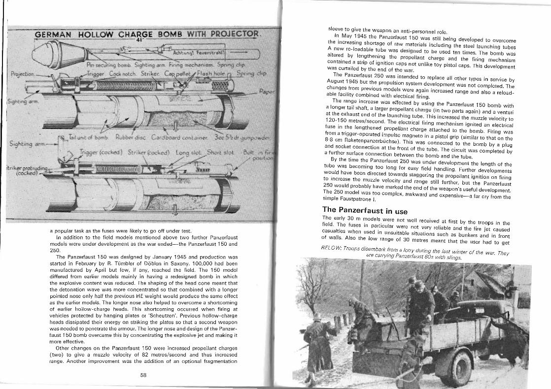
UI; "~I"\ I" HOllOW CHARGE DVM D """• • ~ ----- ~ -1 • =:l"C--- 41 • .
a popular task as the fuses were likely to go off under test . In addition to the field models mentioned above two further Panzerfaust
models were under development as the war ended-the Panzerfaust 150 and 250.
The Panzerfaust 150 was designed by January 1945 and production was started in February by R. Tumbler of Doblen in Saxony. 100,000 had been manufactured by April but few, if any, reached the field. The 150 model differed from earlier models mainly in having a redesigned bomb in which the explosive content was reduced. The shaping of the head cone meant that the detonation wave was more concentrated so that combined with a longer pointed nose only half the previous HE weight would produce the same effect as the earlier models. The longer nose also helped to overcome a shortcoming of earlier hollow~charge heads. This shortcoming occurred when firing at vehicles protected by hanging plates or 'Scheutzen'. Previous hollow-charge heads dissipated their energy on striking the plates so that a second weapon was needed to penetrate the armour. The longer nose and design of the Panzerfaust 150 bomb overcame this by concentrating the explosive jet and making it more effective.
Other changes on the Panzerfaust 150 were increased propellant charges (two) to give a muzzle velocity of 82 metres/second and thus increased range. Another improvement was the addition of an optional fragmentation
58
sleeve to give the weapon an anti-personnel role.
In May 1945 the Panzerfaust 150 was still being developed to overcome the increasing Shortage of raw materials including the steel launChing tubes A new re-Ioadable tube was designed to be used ten times. The bomb was altered by lengthening the propellant charge and the firing mechanism contained a strip of ignition caps not unlike toy pistol caps. This development was curtailed by the end of the war.
The Panzerfaust 250 was intended to replace all other types in service by August 1945 but the propulsion system development was not completed. The changes from previous models were again increased range and also a reloadable facility combined with electrical firing.
The range increase was effected by using the Panzerfaust 150 bomb with a longer tail shaff, a larger propellant charge (in two parts again) and a venturi at the exhaust end of the launching tube. This increased the muzzle velocity to 120-150 metres/second. The electrical firing mechanism ignited an electrical fuse in the lengthened propellant charge attached to the bomb. Firing was from a trigger~operated impulse magneto in a pistol grip (similar to that on the 8·8 cm Raketenpanzerbuchse) . This was connected to the bomb by a plug and socket connection at the front of the tu be. The circuit was completed by a further surface connection between the bomb and the tube.
By the time the Panzerfaust 250 was under development the length of the tube was becoming too long for easy field handling. Further developments would have been directed towards staggering the propellant ignition on firing to increase the muzzle velOCity and range still further, but the Panzerfaust 250 would probably have marked the end of the weapon's useful development. The 250 model was too complex, awkward and expensive-a far cry from the Simple Faustpatrone I.
The Panzerfaust in use The early 30 m models were not well received at first by the troops in the field. The fuses in particular were not very reliable and the fire jet caused casualties when used in unsuitable situations such as bunkers and in front of walls. Also the low range of 30 metres meant that the user had to get
BELOW: Troops disembark from a lorry during the last winter of the war. They are carrying Panzerfaust 60s with slings.
' ~." ~-~. • . .., ---::=;:r:o.~,
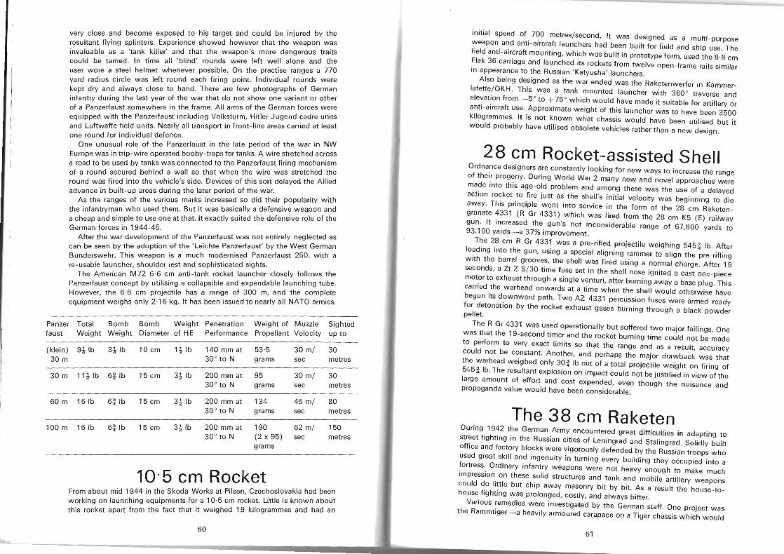
very close and become exposed to his target and could be injured by the resultant flying splinters. Experience showed however that the weapon was invaluable as a 'tank killer' and that the weapon's more dangerous traits could be tamed. In time all 'blind' rounds were left well alone and the user wore a steel helmet whenever possible , On the practise ranges a 770 yard radius circle was left round each firing point. Individual rounds were kept dry and always close to hand. There are few photographs of German infantry during the last year of the war that do not show one variant or other of a Panzerfaust somewhere in the frame. All arms of the German forces were equipped with the Panzerfaust including Volksturm, Hitler Jugend cadre units and Luftwaffe field units. Nearly all transport in front-line areas carried at least one round for individual defence.
One unusual role of the Panzerfaust in the late period of the war in NW Europe was in trip-wire operated booby-traps for tanks. A wire stretched across a road to be used by tanks was connected to the Panzerfaust firing mechanism of a round secured behind a wall so that when the wire was stretched the round was fired into the vehicle's side. Devices of this sort delayed the Allied advance in built-up areas during the later period of the war.
As the ranges of the various marks increased so did their popularity with the infantryman who used them. But it was basically a defensive weapon and a cheap and simple to use one at that. It exactly suited the defensive role of the German forces in 1944-45.
After the war development of the Panzerfaust was not entirely neglected as can be seen by the adoption of the 'Leichte Panzerfausf by the West German Bunderswehr. This weapon is a much modernised Panzerfaust 250, with a re-usable launcher, shoulder rest and sophisticated sights.
The American M72 6·6 cm anti-tank rocket launcher closely follows the Panzerfaust concept by utilising a collapsible and expendable launching tube. However, the 6·6 cm projectile has a range of 300 m, and the complete equipment weighs only 2·16 kg. It has been issued to nearly all NATO armies.
Panzer faust
Total Weight
Bomb Weight
Bomb Diameter
Weight of HE
Penetration Performance
Weight of Propellant
Muzzle Velocity
Sighted up to
(klein) 30 m
9~lb 3~lb 10 cm 1~ Ib 140mmat 30° to N
53·5 30 m/ grams sec
30 metres
30 m 11~ Ib 6ilb 15 cm 3~lb 200 mm at 30° to N
95 grams
30 m/ sec
30 metres
60 m 15 Ib 6ilb 15 cm 3~lb 200 mm at 30° to N
134 grams
45 m/ sec
80 metres
100 m 151b 6ilb 15 cm 3~ Ib 200 mm at 30 ° to N
190 (2 x 95) grams
62 m/ sec
150 metres
10-5 em Rocket From about mid 1944 in the Skoda Works at Pilsen, Czechoslovakia had been working on launching equipments for a 10·5 cm rocket. Little is known about this rocket apart from the fact that it weighed 19 kilogrammes and had an
60
initial speed of 700 metres/second. It was designed as a multi-purpose weapon and anti-aircraft launchers had been built for field and ship use. The field anti-aircraft mounting, which was built in prototype form, used the 8·8 cm Flak 36 carriage and launched its rockets from twelve open-frame rails similar in appearance to the Russian 'Katyusha' launchers .
Also being designed as the war ended was the Raketenwerfer in Kammerlafette/ OKH. This was a tank mounted launcher with 360 0 traverse and elevation from _5° to +75 ° which would have made it suitable for artillery or anti-aircraft use. Approximate weight of this launcher was to have been 3500 kilogrammes. It is not known what chassis would have been utilised but it would probably have utilised obsolete vehicles rather than a new design.
28 em Rocket-assisted Shell Ordnance designers are constantly looking for new ways to increase the range of their progeny. During World War 2 many new and novel approaches were made into this age-old problem and among these was the use of a delayed action rocket to fire just as the shell's initial velocity was beginning to die away. This principle went into service in the form of the 28 cm Raketengranate 4331 (R Gr 4331) which was fired from the 28 cm K5 (E) railway gun. It increased the gun's not inconsiderable range of 67,800 yards to 93,100 yards-a 37% improvement.
The 28 cm R Gr 4331 was a pre-rifled projectile weighing 545% lb. After loading into the gun, using a special aligning rammer to align the pre-rifling with the barrel grooves, the shell was fired using a normal charge. After 19 seconds, a Zt Z S/30 time fuse set in the shell nose ignited a cast one-piece motor to exhaust through a single venturi, after burning away a base plug. This carried the warhead onwards at a time when the shell would otherwise have begun its downward path. Two AZ 4331 percussion fuses were armed ready for detonation by the rocket exhaust gases burning through a black powderpellet.
The R Gr 4331 was used operationally but SUffered two major failings. One was that the 19-second timer and the rocket burning time could not be made to perform to very exact limits so that the range and as a result, accuracy could not be constant. Another, and perhaps the major drawback was that the warhead weighed only 30l lb out of a total projectile weight on firing of 545llb. The resultant explosion on impact could not be justified in view of the large amount of effort and cost expended, even though the nuisance and propaganda value would have been considerable.
The 38 em Raketen During 1942 the German Army encountered great difficulties in adapting to street fighting in the Russian cities of Leningrad and Stalingrad. Solidly built office and factory blocks were vigorously defended by the Russian troops who used great skill and ingenuity in turning every building they occupied into a fortress. Ordinary infantry weapons were not heavy enough to make much impression on these solid structures and tank and mobile artillery weapons could do little but chip away masonry bit by bit. As a result the house-tohouse fighting was prolonged, costly, and always bitter.
Various remedies were investigated by the German staff. One project was the Rammtiger-a heavily armoured carapace on a Tiger chassis which would
61
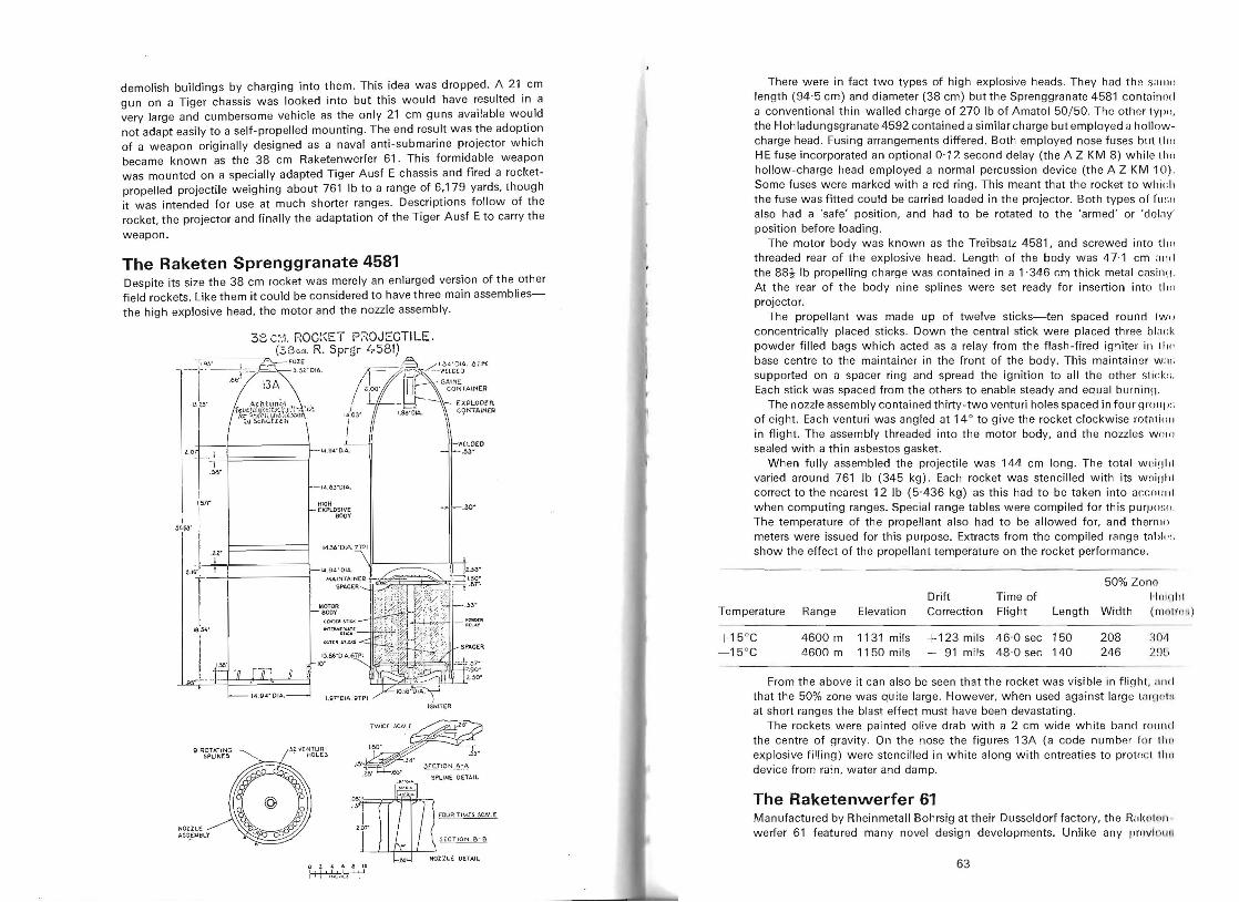
demolish buildings by charging into them. This idea was dropped. A 21 cm gun on a Tiger chassis was looked into but this would have resulted in a very large and cumbersome vehicle as the only 21 cm guns available would not adapt easily to a self-propelled mounting. The end result was the adoption of a weapon originally designed as a naval anti-submarine projector which became known as the 38 cm Raketenwerfer 61. This formidable weapon was mounted on a specially adapted Tiger Ausf E chassis and fired a rocketpropelled projectile weighing about 761 Ib to a range of 6,179 yards, though it was intended for use at much shorter ranges. Descriptions follow of the rocket, the projector and finally the adaptation of the Tiger Ausf E to carry the
weapon.
The Raketen Sprenggranate 4581 Despite its size the 38 cm rocket was merely an enlarged version of the other field rockets. Like them it could be considered to have three main assembliesthe high explosive head, the motor and the nozzle assembly.
38 C;.1. ROC:~ET PROJECTILE. .-ccc-
. l l" ~
1.4.9 <1 " 0 14 ,
MOTOR 800V
---,= (38 cm. R. Sprgr i.-581) 119Y ,- · fuZE
-'--l - jC:='I;A " ,'01.
I . 13l5" <: ~,~~t~ln9.: ' ......d;'. ;..
1.,~c!t~;.J(·li i:[ii\~)~ .~ .
I ~iJ Sti'iot l e il
w(\,OEO 14.94- 0 1A.. . ~3~,04
Ir. -IA .~YD IA.
1 , I~r HIGH EXPLOSIVE -.30
BODY ,,~. I
t ,U; -'
I6.S"·
IGNITER
TWICr.,~~.60 ' . 'J;
/ ·s'
~ ··
~ l. "'ENT U ~ I g R~pT~~I~G ~ . HOL.£S .". = .J;.
.z.a' .E{). JL0.!Q 1'J_~·A
~".omn O~~~'L~~:.;:: SPLINEtr::l .J4 '
.fY' -
l .or rOUR TlM[.5 SCALE
HOl.ILE A~!;!=MBLY ~ L ..' ,He n ON B- B
oI I I 2. ' 4!1 fiI ~ , 110 Nt NOZZLE DETAIL.
There were in fact two types of high explosive heads. They had the S;lIl1ll
length (94'5 cm) and diameter (38 cm) but the Sprenggranate 4581 contuin o<i a conventional thin-walled charge of 270 Ib of Amatol 50/50. Th e other lyp", the Hohladungsgranate 4592 contained a similar charge but employed a hollowcharge head. Fusing arrangements differed . Both employed nose fuses but lho HE fuse incorporated an optional 0·12 second delay (the A Z KM 8) while lho hollow-charge head employed a normal percussion device (the A Z KM 10) . Some fuses were marked with a red ring. This meant that the rocket to whi, ;h the fuse was fitted could be carried loaded in the projector. Both types of fU SI) also had a 'safe' position, and had to be rotated to the 'armed' or 'doklY' position before loading,
The motor body was known as the Treibsatz 4581, and screwed into tho threaded rear of the explosive head. Length of th e body was 47·1 cm ,111(1 the 88~ Ib propelling charge was contained in a 1·346 cm thick metal casino. At the rear of the body nine splines were set ready for insertion into [hn projector.
The propellant was made up of twelve sticks-ten spaced round [WI)
concentrically placed sticks, Down the central stick were placed three blnck powder filled bags which acted as a relay from the flash-fired igniter ill III<' base centre to the maintainer in the front of the body. This maintainer W ; I! ;
supported on a spacer ring and spread the ignition to all the other stick:;, Each stick was spaced from the others to enable steady and equal burninn.
The nozzle assembly contained thirty -two venturi holes spaced in four group:; of eight . Each venturi was angled at 14° to give the rocket clockwise rNnli()l) in flight. The assembly threaded into the motor body, and the nozzles W(JJfJ
sealed with a thin asbestos gasket. When fully assembled the projectile was 144 cm long. The total wl,iqlil
varied around 761 Ib (345 kg) . Each rocket was stencilled with its w oi(J111 correct to the nearest 12 Ib (5-436 kg) as this had to be taken into acc(lI"ll when computing ranges. Special range tables were compiled for this purpo,;o. The temperature of the propellant also had to be allowed for, and themJ() meters were issued for this purpose. Extracts from the compiled rang e tnl>l,, :; show the effect of the propellant temperature on the rocket performance .
Temperature Range Elevation Drift Correction
Time of Flight Length
50% ZOllO
II0lillii Width (J1l 0 IH IiI )
115°C - 15°C
4600 m 4600 m
1131 mils 1150 mils
+ 123 mils + 91 mils
46·0 sec 48 ·0 sec
150 140
208 246
:~ Ol\
2%
From the above it can also be seen that the rocket was visible in flight, ;llId
that the 50% zone was quite large. However, when used against large [;1r!i' , I : .•
at short rang es the blast effect must have been devastating. The rockets were painted olive drab with a 2 cm wide white band I"OlIlId
the centre of gravity. On the nose the figures 13A (a code number for Iii " explosive filling) were stencilled in white along with entreaties to protncl 1111) device from rain, water and damp.
The Raketenwerfer 61 Manufactured by Rheinmetall Bohrsig at their Dusseldorf factory, the R"l<oll)1I werfer 61 featured many novel design developments. Unlike any provl l1 l." ,
63
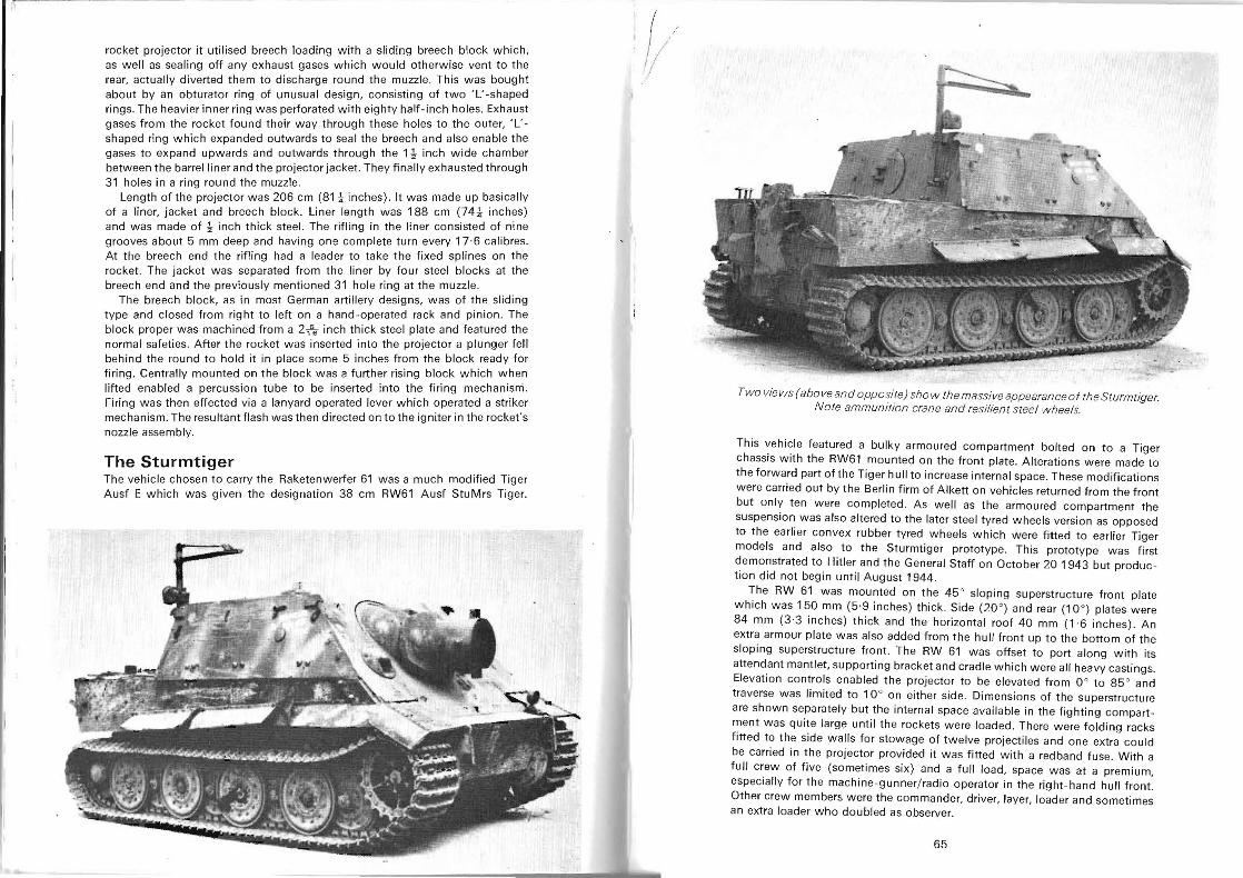
rocket projector it utilised breech loading with a sliding breech block which, as well as sealing off any exhaust gases which would otherwise vent to the rear, actually diverted them to discharge round the muzzle. This was bought about by an obturator ring of unusual design, consisting of two 'L' -shaped rings. The heavier inner ring was perforated with eighty half-inch holes. Exhaust gases from the rocket found their way through these holes to the outer, 'L'shaped ring which expanded outwards to seal the breech and also enable the gases to expand upwards and outwards through the 1t inch wide chamber between the barrel liner and the projector jacket. They finally exhausted through 31 holes in a ring round the muzzle.
Length of the projector was 206 cm (81 ~ inches). It was made up basically of a liner, jacket and breech block. Liner length was 188 cm (74l inches) and was made of t inch thick steel. The rifling in the liner consisted of nine grooves about 5 mm deep and having one complete turn every 17·6 calibres. At the breech end the rifling had a leader to take the fixed splines on the rocket. The jacket was separated from the liner by four steel blocks at the breech end and the previously mentioned 31 hole ring at the muzzle.
The breech block, as in most German artillery designs, was of the sliding type and closed from right to left on a hand -operated rack and pinion. The block proper was machined from a 2fs inch thick steel plate and featured the normal safeties. After the rocket was inserted into the projector a plunger fell behind the round to hold it in place some 5 inches from the block ready for firing. Centrally mounted on the block was a further rising block which when lifted enabled a percussion tube to be inserted into the firing mechanisni . Firing was then effected via a lanyard operated lever which operated a striker mechanism. The resultant flash was then directed on to the igniter in the rocket's nozzle assembly.
The Sturmtiger The vehicle chosen to carry the Raketenwerfer 61 was a much modified Tiger Ausf E which was given the designation 38 cm RW61 Ausf StuMrs Tiger.
~/
Two views (above and opposite) sho w themassive appearan ceo f the S turmtiger. Note ammunition crane and resilient steel wheels.
This vehicle featured a bulky armoured compartment bolted on to a Tiger chassis with the RW61 mounted on the front plate. Alterations were made to the forward part of the Tiger hull to increase internal space. These modifications were carried out by the Berlin firm of Alkett on vehicles returned from the front but only ten were completed . As well as the armoured compartment the suspension was also altered to the later steel tyred wheels version as opposed to the earlier convex rubber tyred wheels which were fitted to earlier Tiger models and also to the Sturmtiger prototype. This prototype was first demonstrated to Hitler and the General Staff on October 20 1943 but production did not begin until August 1944.
The RW 61 was mounted on the 45° sloping superstructure front plate which was 150 mm (5 '9 inches) thick . Side (20 °) and rear (10°) plates were 84 mm (3'3 inches) thick and the horizontal roof 40 mm (1'6 inches) . An extra armour plate was also added from the hu II front up to the bottom of the sloping superstructure front. The RW 61 was offset to port along with its attendant mantlet, supporting bracket and cradle which were all heavy castings. Elevation controls enabled the projector to be elevated from 0 ° to 85 ° and traverse was limited to 10° on either side. Dimensions of the superstructure are shown separately but the internal space available in the fighting compartment was quite large until the rockets were loaded. There were folding racks fitted to the side walls for stowage of twelve projectiles and one extra could be carried in the projector provided it was fitted with a redband fuse. With a full crew of five (sometimes six) and a full load, space was at a premium, especially for the machine-gunner/ radio operator in the right-hand hull front. Other crew members were the commander, driver, layer, loader and sometimes an extra loader who doubled as observer.
65
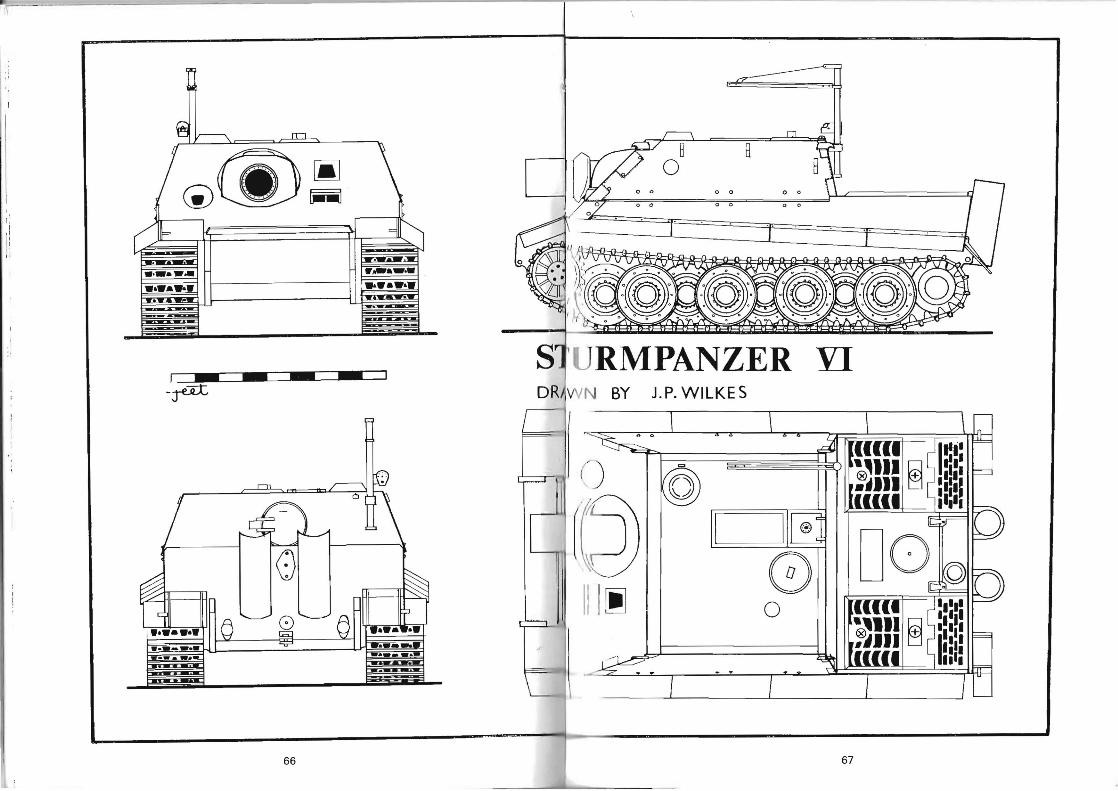
--.
.:.... .
.
Ol
O
l
o 0
o 0
. 0
=,
o 0
. 0
0
=
o 0
. 0
0
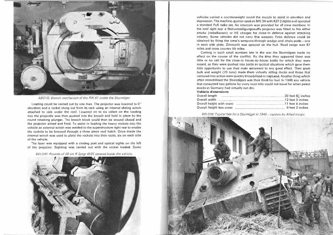
ABOVE: Breech mechanism of the RW 61 inside the Sturmtiger.
Loading could be carried out by one man. The projector was lowered to 0° elevation and a rocket slung out from its rack using an internal sliding winch attached to rails under the roof. Lowered on to six rollers on the loading tray the projectile was then pushed into the breech and held in place by the round retaining plunger. The breech block could then be wound closed and the projector aimed and fired . To assist in loading the heavy rockets into the vehicle an external winch was welded to the superstructure right rear to enable the rockets to be lowered through a three-piece roof hatch. Once inside the internal winch was used to place the rockets into their racks, six on each side of the vehicle.
The layer was equipped with a closing port and optical sights on the left of the projector. Sighting was carried out with the rocket loaded. Some
BELOW: Rounds of 38 cm R Sprgr 4581 stowed inside the vehicle. ,
vehicles carried a counterweight round the muzzle to assist in elevation and depression. The machine-gunner used an MG 34 with KZF 2 sights and operated a standard Fu5 radio set. An intercom was provided for all crew members. In the roof right rear a Nahverteidigungswaffe projector was fitted to fire either smoke (nebelkerzen) or HE charges for close-in defence against attacking infantry. Some vehicles did not carry this weapon. Extra defence could be obtained by firing the crew's weapons through wedge-and -chain ports-one in each side plate. Zimmeritt was sprayed on the hull. Road range was 87 miles and cross country 55 miles.
Coming in such small numbers late in the war the Sturmtigers made no effect on the course of the conflict. By the time they appeared there was little or no call for the close-in house-to- house battle for which they were meant, so they were pushed into battle in tactical situations which gave them little opportunity to use their main armament to any great effect. Their great bulk and weight (70 tons) made them virtually sitting ducks and those that ventured into action were quickly immobilised or captured. Another thing which often immobilised the Sturmtigers was their thirst for fuel. In 1945 any vehicle that consumed two gallons for every road mile could not travel far when petrol stocks in Germany had virtually run dry. Vehicle dimensions Overall length .. . .......................... 20 feet 8~ inches Overall width ............ .. ........ .. ......... .. .. 12 feet 3 inches Overall height with crane .................. .. ................ 11 feet 4 inches Overall height less crane ................... ....... ............. 9 feet 3 inches
BELO W: Tvpica l fate for a Sturmtiger in 1945 - capture bV Allied troops.
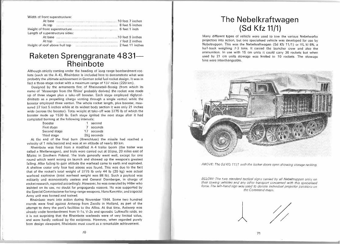
Width of front superstructure: At base .......... . .. . . . ................ . .. . . . . .. . ...... 1 0 feet 7 inches At top ...... .... .. .. .... .. . .. ..... ... .. .. .. .. ...... ... 8 feet 5 inches
Height of front superstructure ....... .. ,. , ' , .. .. . , ... .... , . ..... ' , 6 feet 1 inch Length of superstructure sides:
At base .... . ................. .. ........... .... . ..... .. 10 feet 9 inches At top .. . .. .. .. .. .. .. .. .. .. .. . .. .. ... 7 feet 2 inches
Height of roof above hull top .... .. .. ... .. .. .... .... .......... 2 feet 11 inches
Raketen Sprenggranate 4831Rheinbote
Although strictly coming under the heading of long range bombardment rockets (such as the A-4), Rheinbote is included here to demonstrate what was probably the ultimate achievement in German solid fuel rocket design. It was in fact a three-stage rocket with a maximum range of 137 miles (220 km) .
Designed by the armaments firm of Rheinmetall- Borsig (from which its name of 'Messenger from the Rhine' probably derives) the rocket was made up of three stages plus a take-off booster. Each stage employed diglycoldinitrate as a propelling charge venting through a single venturi while the booster employed three venturi. The whole rocket length, plus booster, measured 37 feet 5 inches while at its widest body section it was only 21 inches wide (across the booster) . Total weight at take-off was 3775 Ib of which the booster made up 1530 lb. Each stage ignited the next stage after it had completed burning at the following intervals:
Booster 1 second First stage 7 seconds Second stage 17 seconds Third stage 25! seconds
At the end of the final burn (Brenchluss) the missile had reached a velocity of 1 mile / second and was at an altitude of nearly 80 km,
Rheinbote was fired from a modified A-4 trailer boom (the trailer was called a Meillerwagen), and trials were carried out at Blizna, 20 miles east of Mielec in Southern Poland, The trials generally went well , except for one round which went wrong on launch and showed up the weapon's greatest failing, After failing to gain altitude the warhead came to earth and exploded. A shallow crater only four feet across was found. This was due to the fact that of the rocket's total weight of 3775 Ib only 44 Ib (20 kg) was actual warhead explosive (total warhead weight was 88 Ib), Such a payload was militarily and economically useless and General Dornberger, in charge of rocket research, reported accordingly, However, he was overruled by Hitler who insisted on its use, no doubt for propaganda reasons. He was supported by the Special Commissioner for long-range weapons, Hans Kammler, and a special Army unit was formed and trained.
Rheinbote went into action during November 1944. Some two hundred rounds were fired against Antwerp from Zwolle in Holland, as part of the attempt to deny the port's facilities to the Allies. At that time, Antwerp was already under bombardment from V-1 s, V-2s and sporadic Luftwaffe raids, so it is not surprising that the Rheinbote warheads were of very limited value, and were hardly noticed by the recipients. However, when regarded purely from design viewpoint, Rheinbote must count as a remarkable achievement.
70
J,
The Nebelkraftwagen (Sd Kfz 11/1)
Many different types of vehicle were used to tow the various Nebelwerfer projectors into action, but one specialised vehicle was developed for use by Nebeltruppen, This was the Nebelkraftwagen (Sd Kfz 11/1) or H L kl 6N, a half-track weighing 7·3 tons. It carried the launcher crew and also the ammunition . In use with 15 cm units it could carry 36 rockets but when used by 21 cm units stowage was limited to 10 rockets, The stowage bins were interchangeable.
ABO VE: The Sd Kfz 11/1 With the locker doors open showing storage racking,
BELOW: Th e two standard tactical signs carried by all Nebeltruppen unirs on their towing vehicles and any other transport concerned with this specialised force. The le ft- hand sign was used to denote individual projector p ositions on
the Command maps.
1 ~ 71
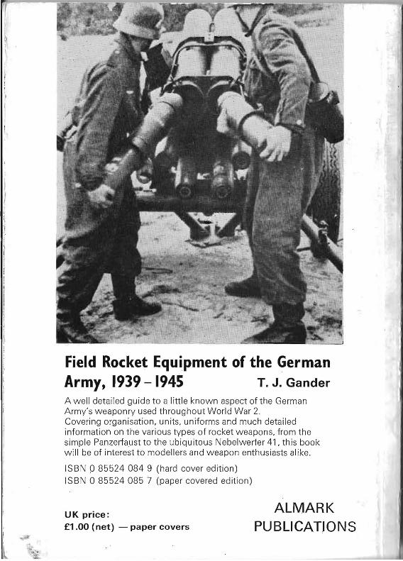
Field Rocket Equipment of the German Army, 1939 - 1945 T. J. Gander A well detailed guide to a little known aspect of the German Army's weaponry used throughout World War 2. Covering organisation, units, uniforms and much detailed information on the various types of rocket weapons, from the simple Panzerfaust to the ubiquitous Nebelwerfer 41, this book will be of interest to modellers and weapon enthusiasts alike.
ISBN 085524084 9 (hard cover edition) ISBN 0 85524 085 7 (paper covered edition)
ALMARKUK price: £1.00 (net) - paper covers PUBLICATIONS
~" ;' Y " '