Embed Size (px)
Citation preview
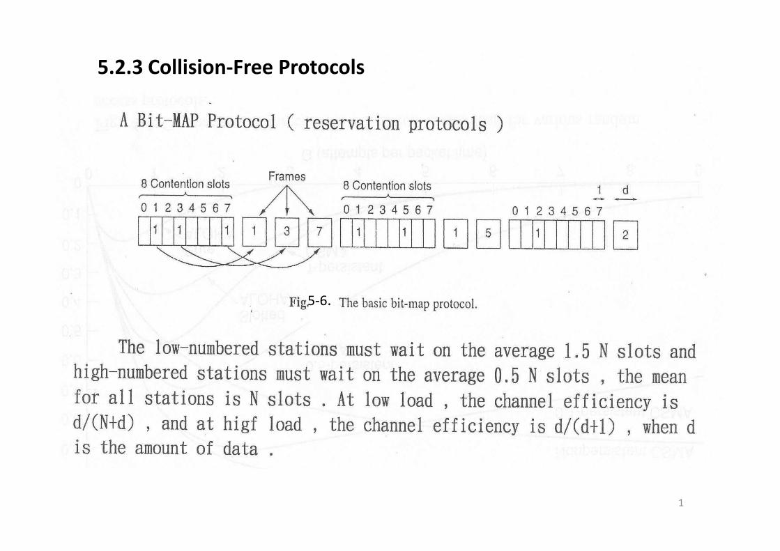
5.2.3 Collision‐Free Protocols
5‐6.
1
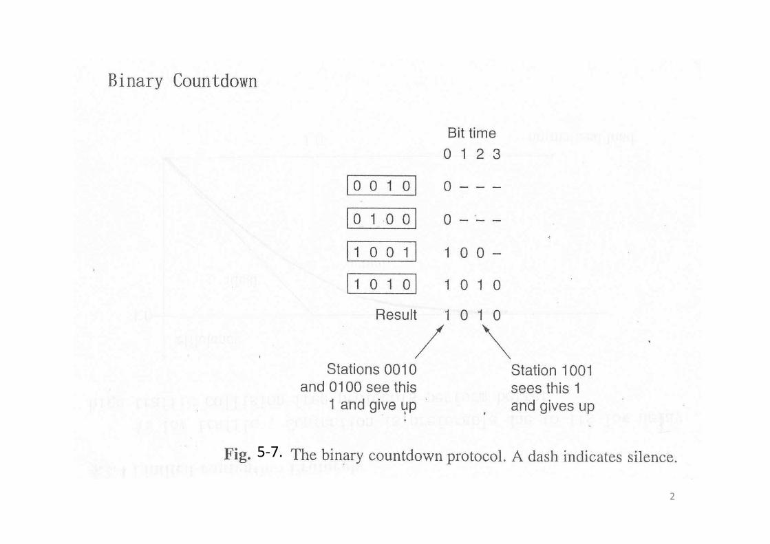
5‐7.
2
3
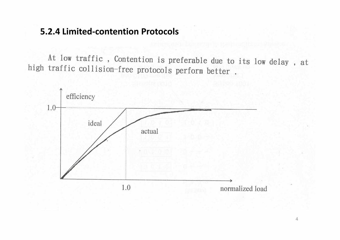
5.2.4 Limited‐contention Protocols
4
Limited‐Contention protocolsLimited‐Contention protocols
5

6
7
8
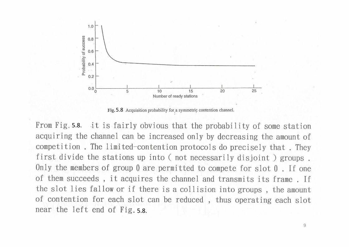
5.8
5 85.8.
9
5.8.
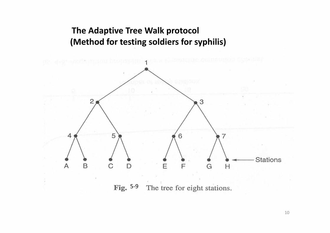
The Adaptive Tree Walk protocol(Method for testing soldiers for syphilis)
5‐9
10

11
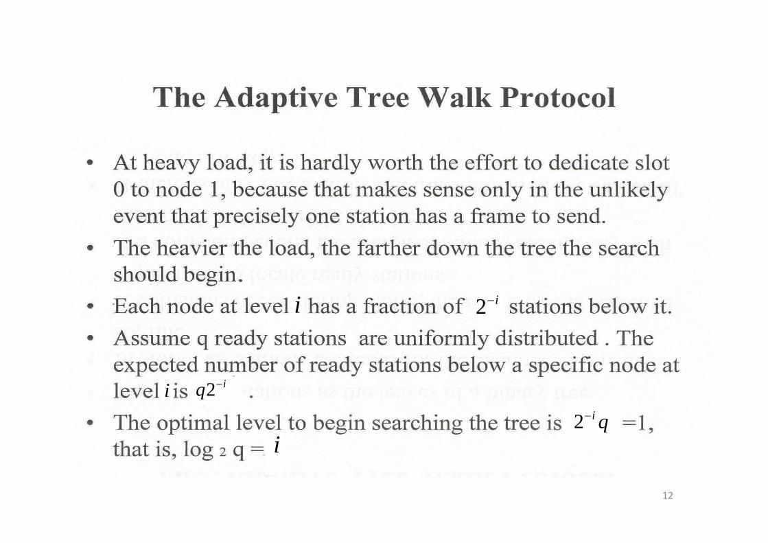
i i−2
i iq −2i
i
q2
qi−2
12
5.2.6 Wireless LAN Protocols
13
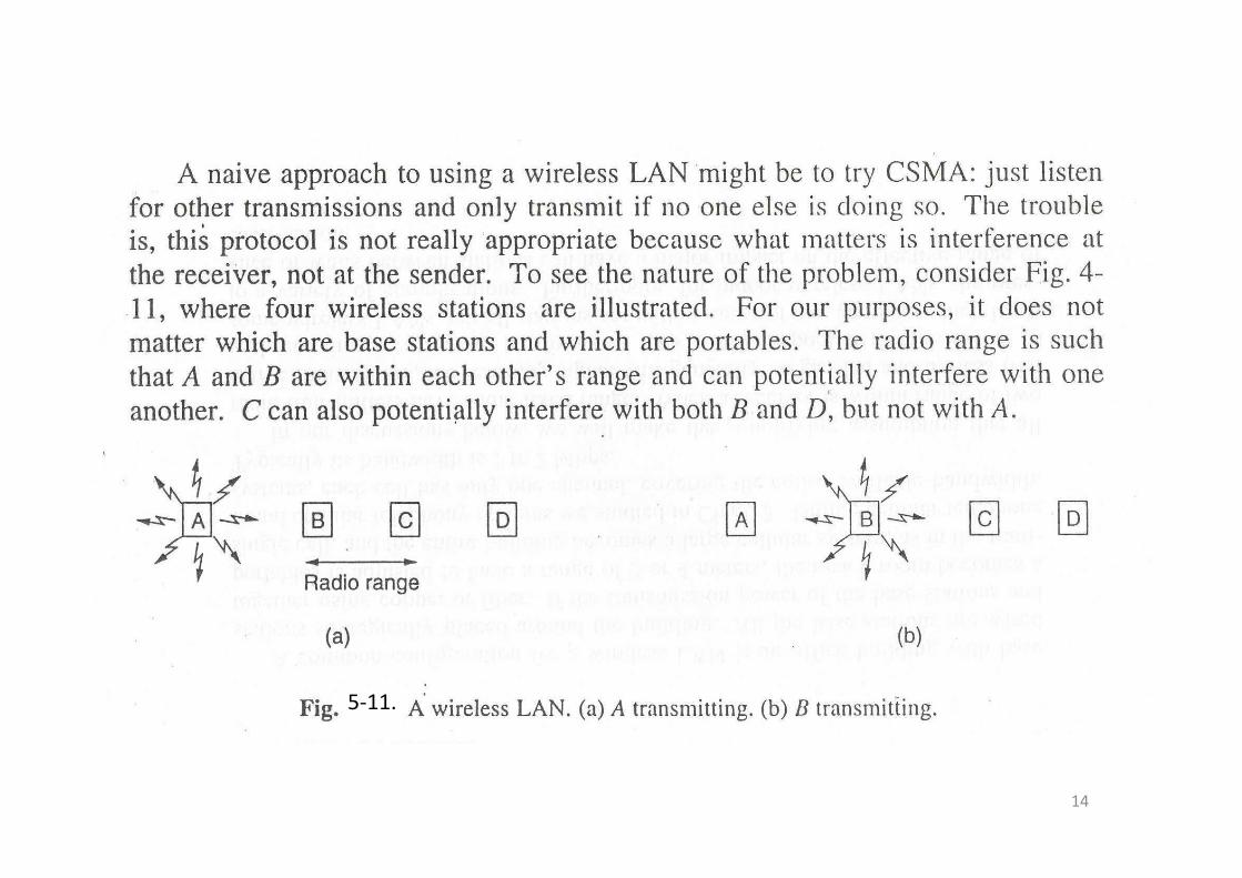
5‐11.
14
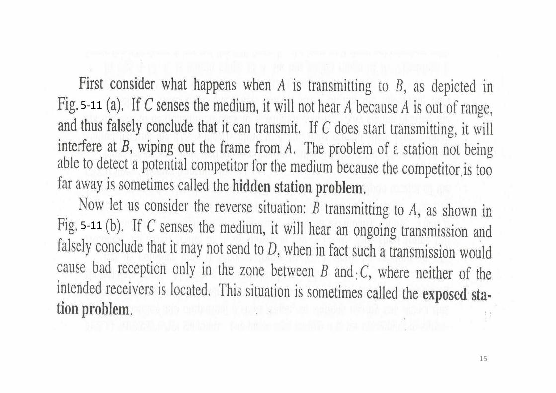
5‐115 11
5‐11
15
5‐12.
5‐12
5‐12
5‐12,
16
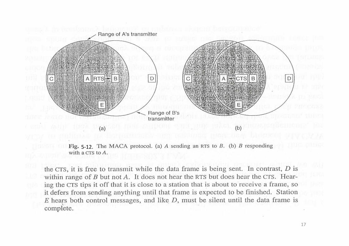
5‐12.
17
18
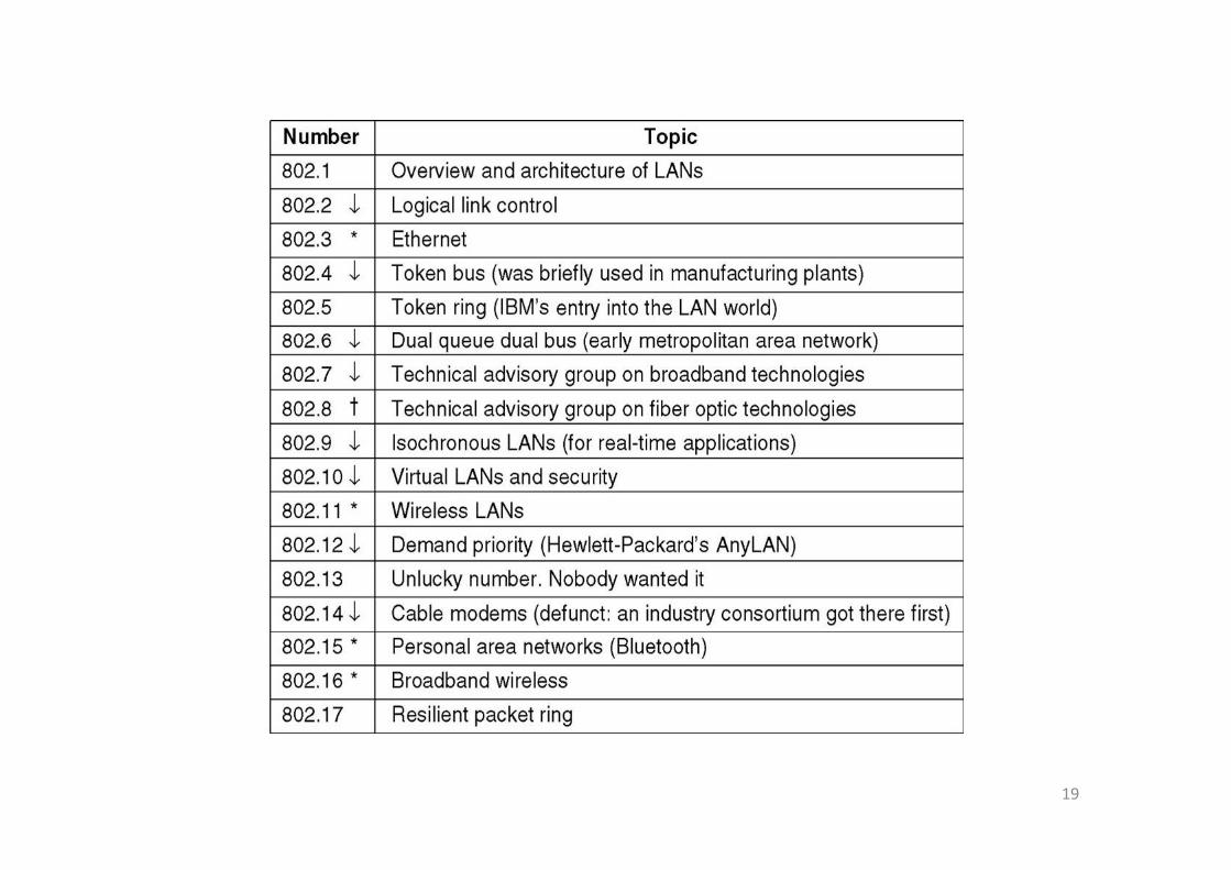
19
5.3 Ethernet• Ethernet Cabling• Manchester Encoding• The Ethernet MAC Sublayer ProtocolThe Ethernet MAC Sublayer Protocol• The Binary Exponential Backoff Algorithm• Ethernet Performance• Switched Ethernet• Fast Ethernet• Gigabit Ethernet• Gigabit Ethernet• IEEE 802.2: Logical Link Control
20• Retrospective on Ethernet
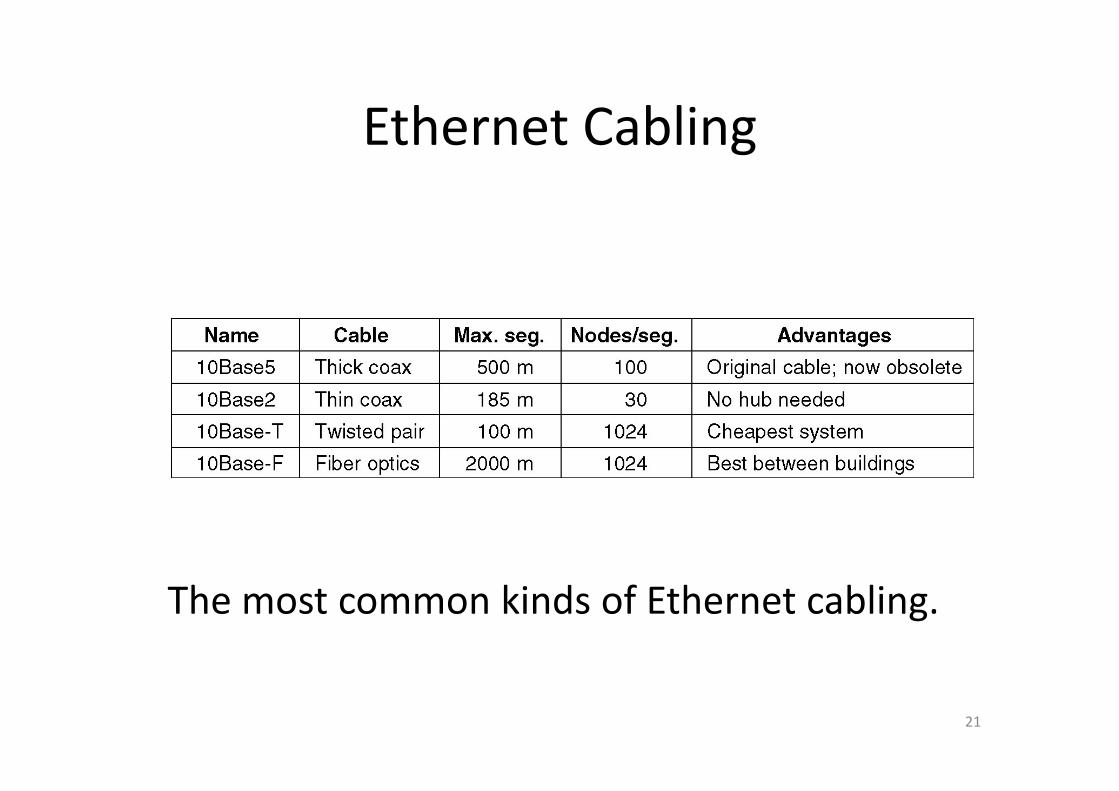
Ethernet CablingEthernet Cabling
The most common kinds of Ethernet cabling.
21
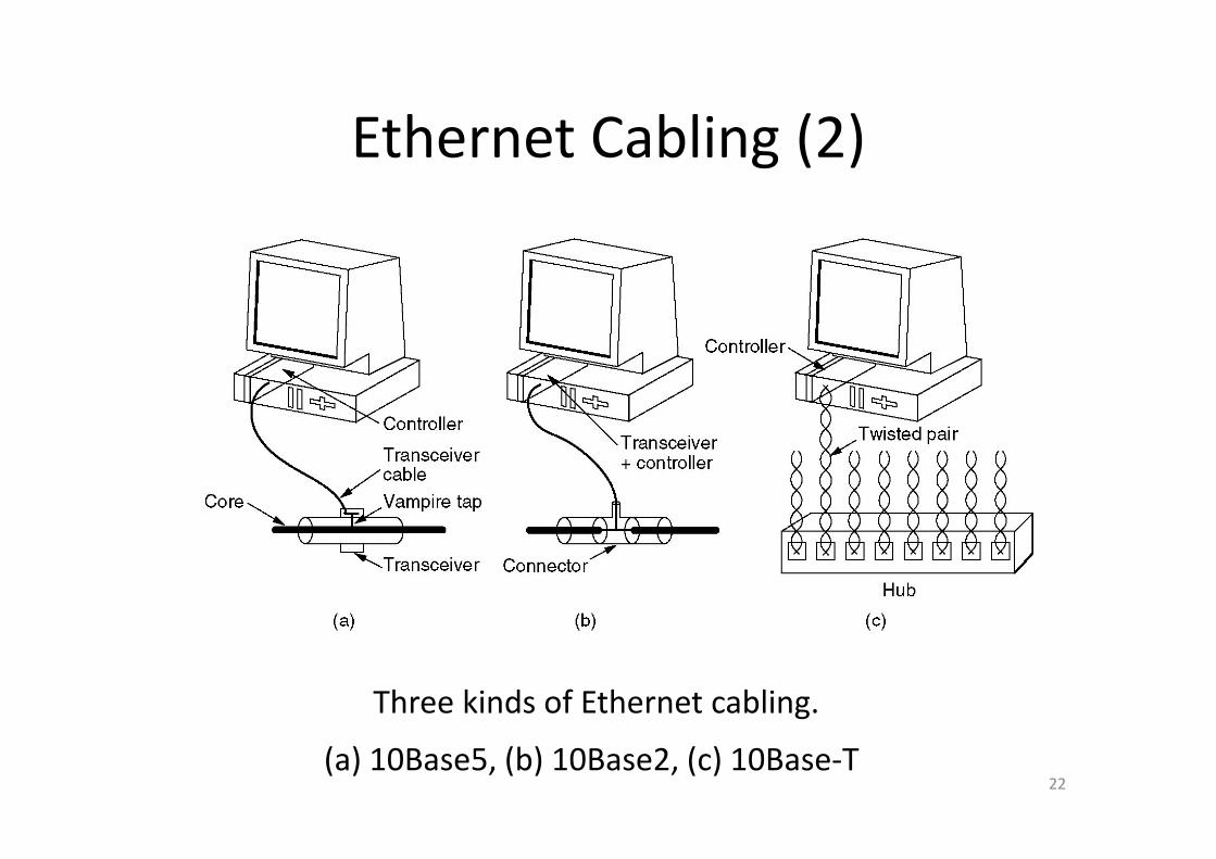
Ethernet Cabling (2)Ethernet Cabling (2)
Three kinds of Ethernet cabling.
(a) 10Base5, (b) 10Base2, (c) 10Base‐T.(a) 10Base5, (b) 10Base2, (c) 10Base T.
Three kinds of Ethernet cabling.
22(a) 10Base5, (b) 10Base2, (c) 10Base‐T
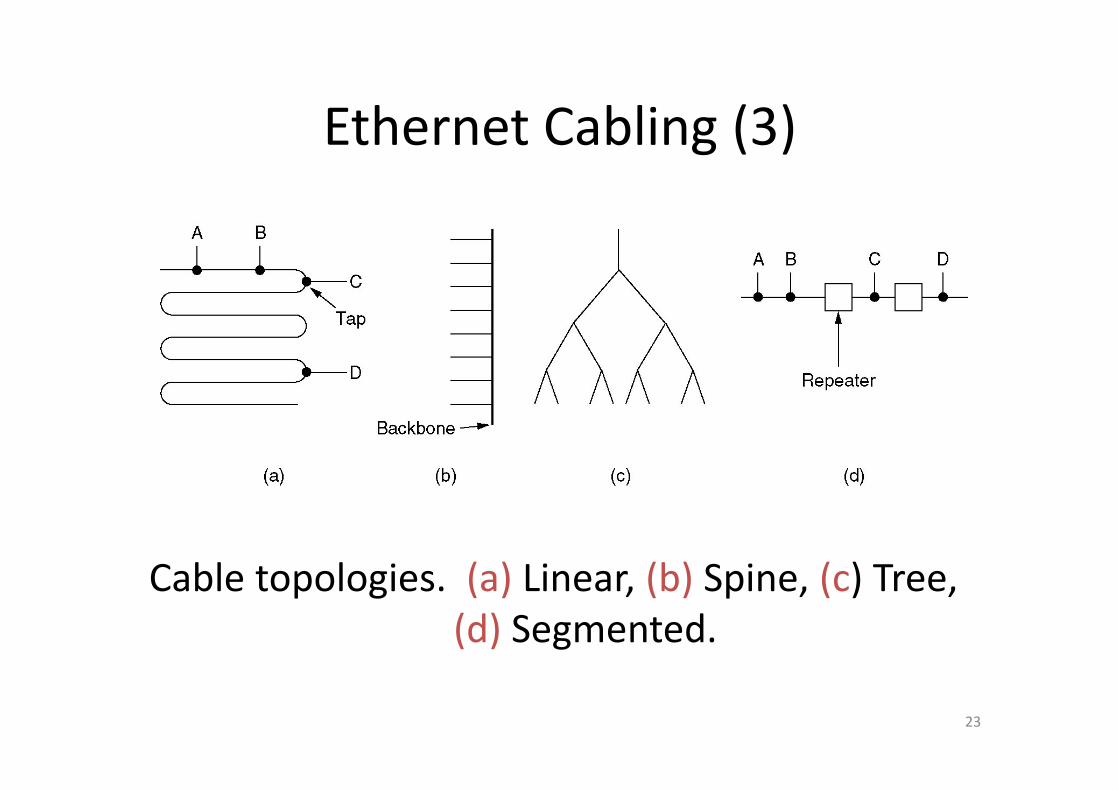
Ethernet Cabling (3)Ethernet Cabling (3)
Cable topologies (a) Linear (b) Spine (c) TreeCable topologies. (a) Linear, (b) Spine, (c) Tree, (d) Segmented.
23
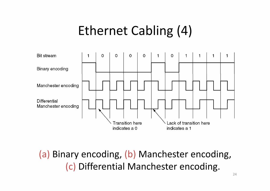
Ethernet Cabling (4)Ethernet Cabling (4)
(a) Binary encoding, (b) Manchester encoding,
24
(c) Differential Manchester encoding.
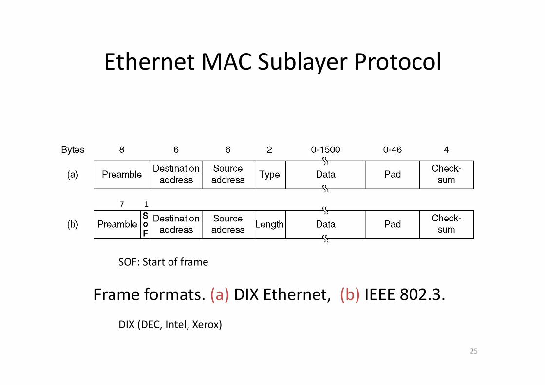
Ethernet MAC Sublayer ProtocolEthernet MAC Sublayer Protocol
7 1
SOF: Start of frame
Frame formats. (a) DIX Ethernet, (b) IEEE 802.3.
DIX (DEC Intel Xerox)
25
DIX (DEC, Intel, Xerox)

Ethernet MAC Sublayer Protocol (2)Ethernet MAC Sublayer Protocol (2)
Collision detection can take as long as 2τ26
Collision detection can take as long as 2 .τ

5.3 Ethernet performance5.3 Ethernet performance
Assumptions
a. Heavy and constant load, that is, stations always ready to transmit
kalways ready to transmit
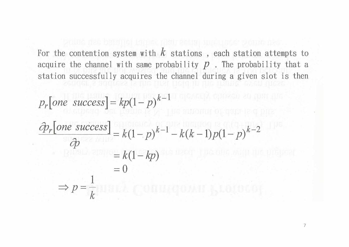
b. Each station transmits during a contention slot with probability
The probability A that some station acquires the
p
The probability A that some station acquires the channel in that slot is
1k
A is maximized when ,
1)1( −−= kpkpAkp 1=
27
A is maximized when ,
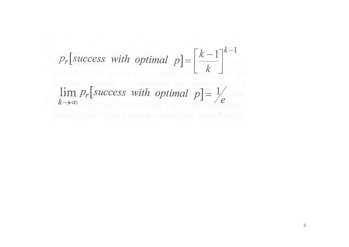
with as
p
eA 1→ ∞→k
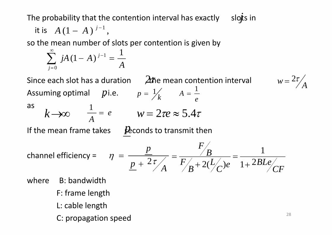
The probability that the contention interval has exactly slots in
it is j
,)1( 1−− jAAso the mean number of slots per contention is given by
AAjA j 1)1( 1 =−∑
∞−
Since each slot has a duration , the mean contention interval
A i ti l i
Aj 0∑=
τ2 Aw τ2=p 1 A 1Assuming optimal , i.e.
as
p kp 1=e
A 1=
∞→k eA
=1 ττ 4.52 ≈= ew
If the mean frame takes seconds to transmit then A
pF
channel efficiency =
Ap
pτη 2+
=CF
BLeeCL
BF
BF
211
)(2 +=
+=
where B: bandwidth
F: frame length
A CFCB
28
L: cable length
C: propagation speed
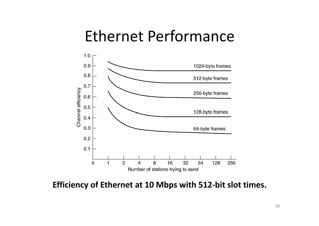
Ethernet PerformanceEthernet Performance
Efficiency of Ethernet at 10 Mbps with 512‐bit slot times.
29
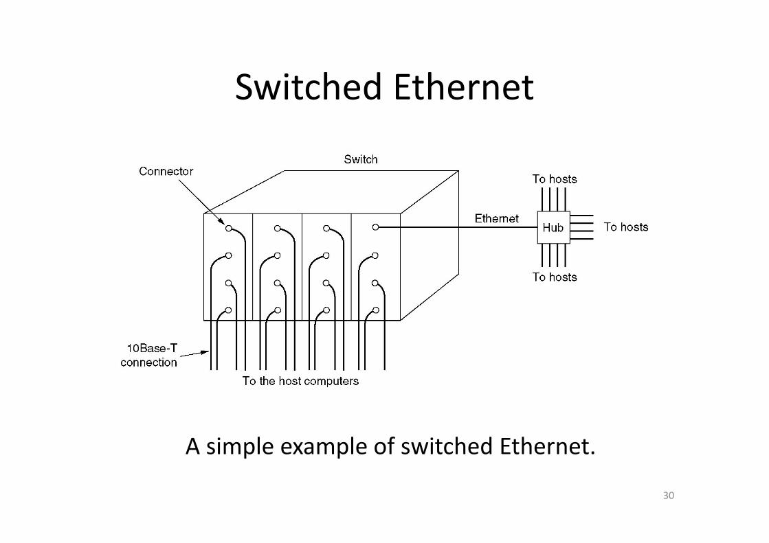
Switched EthernetSwitched Ethernet
A simple example of switched Ethernet.
30
p p

Fast EthernetThe reasons for fast Ethernet
1 The need to be backward compatible with existing Ethernet LANs1. The need to be backward compatible with existing Ethernet LANs
2. The fear that a new protocol might have unforeseen problems
3. The desire to get the job done before the technology changed
All fast Ethernet systems use hubs and switches
100 Base‐T4 uses 8B/6T coding and 100 Base‐TX uses 4B/5B coding
The original fast Ethernet cabling
100 Base‐T4 uses 8B/6T coding and 100 Base‐TX uses 4B/5B coding
31
The original fast Ethernet cabling.

Gigabit Ethernetg• All configurations of gigabit Ethernet are point‐to‐point
• Gigabit Ethernet supports full‐duplex mode (with switch) and half‐duplex‐mode (with hub) Gigabit Ethernet supports full duplex mode (with switch) and half duplex mode (with hub)
• CSMA/CD protocol is required for half‐ duplex mode operation (maximum distance is 25 meters)
• When carrier extension (512 bytes frame) and frame bursting are used the distance can be 200meters
32(a) A two‐station Ethernet. (b) A multistation Ethernet.
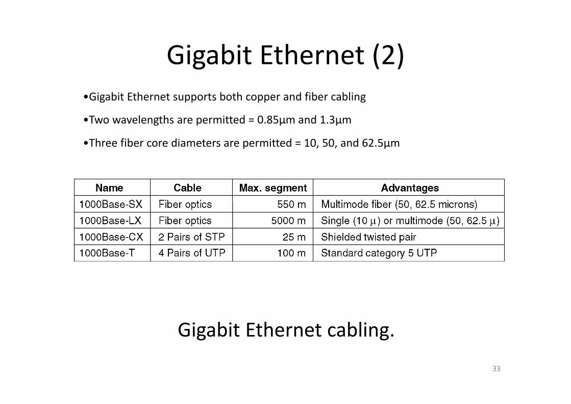
Gigabit Ethernet (2)g ( )•Gigabit Ethernet supports both copper and fiber cabling
•Two wavelengths are permitted = 0.85μm and 1.3μm
•Three fiber core diameters are permitted = 10, 50, and 62.5μm
Gigabit Ethernet cabling.
33
g g

IEEE 802 2: Logical Link ControlIEEE 802.2: Logical Link Control
34
(a) Position of LLC. (b) Protocol formats.

Retrospective on EthernetRetrospective on Ethernet
1 Ethernet is simple and flexible1. Ethernet is simple and flexible
‐ reliable, cheap, easy to maintain, easy
to install
2 Ethernet interworks easily with TCP/IP2. Ethernet interworks easily with TCP/IP
3. Ethernet has been able to evolve in certain crucial ways
‐ speeds gone up‐ speeds gone up
‐ hub and switches introduced
35
Wireless LANsWireless LANs
• The 802.11 Protocol Stack
• The 802.11 Physical Layer
Th 802 11 MAC S bl P t l• The 802.11 MAC Sublayer Protocol
• The 802.11 Frame StructureThe 802.11 Frame Structure
• Services
36
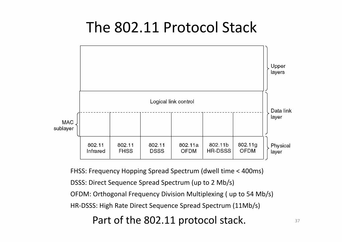
The 802.11 Protocol Stack
FHSS: Frequency Hopping Spread Spectrum (dwell time < 400ms)
DSSS: Direct Sequence Spread Spectrum (up to 2 Mb/s)
OFDM: Orthogonal Frequency Division Multiplexing ( up to 54 Mb/s)
HR DSSS Hi h R Di S S d S (11Mb/ )
37Part of the 802.11 protocol stack.HR‐DSSS: High Rate Direct Sequence Spread Spectrum (11Mb/s)
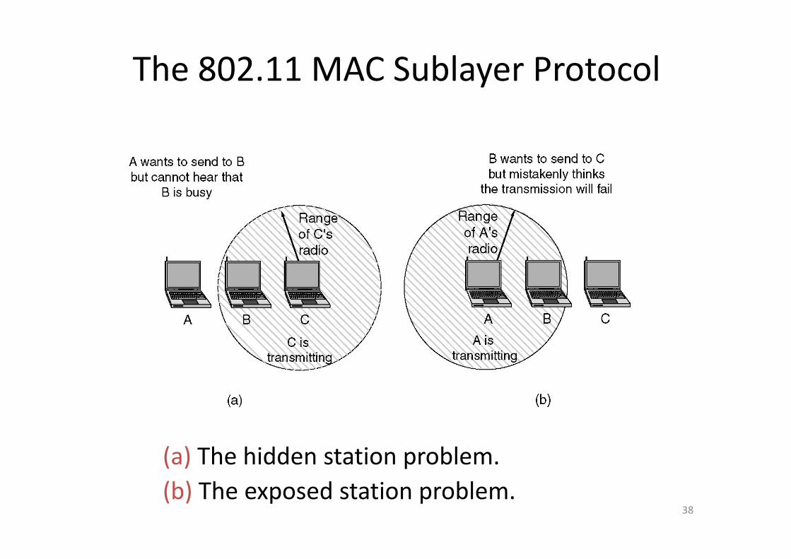
The 802.11 MAC Sublayer Protocol
(a) The hidden station problem.
38(b) The exposed station problem.
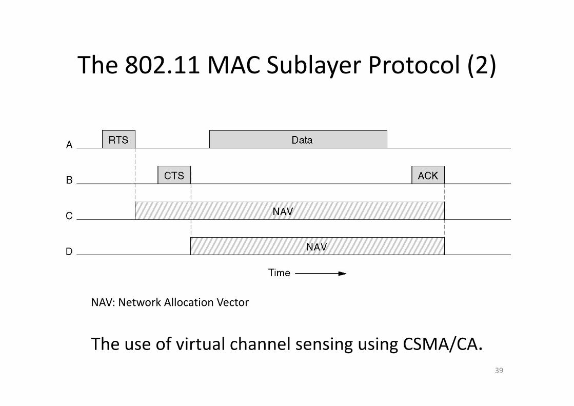
The 802 11 MAC Sublayer Protocol (2)The 802.11 MAC Sublayer Protocol (2)
The use of virtual channel sensing using CSMA/CA
NAV: Network Allocation Vector
39
The use of virtual channel sensing using CSMA/CA.
The 802.11 MAC Sublayer Protocol802.11 supports two modes of operation: DCF and PCF
A. Distributed Coordination Function (DCF)
CSMA/CA (CSMA / i h C lli i A id )uses CSMA/CA (CSMA / with Collision Avoidance)(a) The first mode supported by CSMA/CA
(1) When a station wants to transmit, it senses the channel
(2) If it idle, it just starts transmitting (The sender does not sense the h l hil i i )channel while transmitting)
(3) If the channel is busy, the sender defers until it goes idle and then starts transmittingstarts transmitting
(4) If a collision occurs, it wait a random amount of time (exponential back off) and then try again later
40
back off) and then try again later
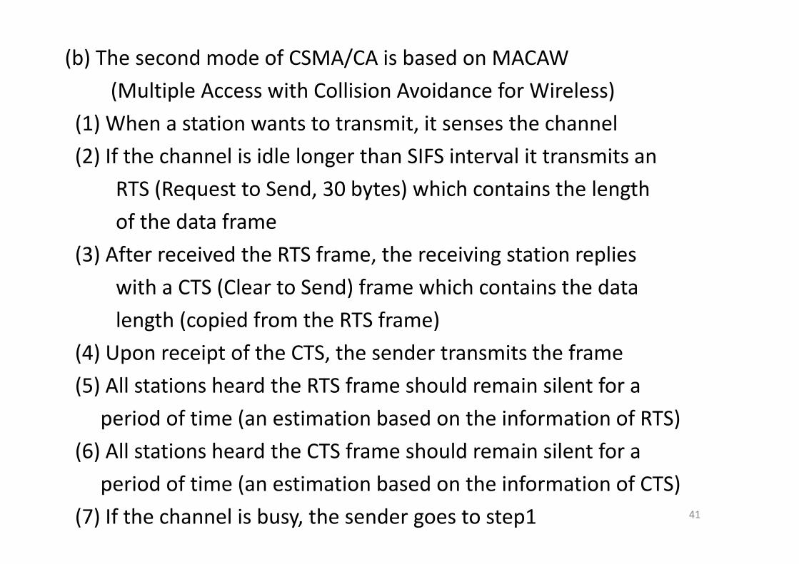
(b) The second mode of CSMA/CA is based on MACAW
(Multiple Access with Collision Avoidance for Wireless)(Multiple Access with Collision Avoidance for Wireless)
(1) When a station wants to transmit, it senses the channel
(2) If the channel is idle longer than SIFS interval it transmits an(2) If the channel is idle longer than SIFS interval it transmits an
RTS (Request to Send, 30 bytes) which contains the length
of the data frameof the data frame
(3) After received the RTS frame, the receiving station replies
ith CTS (Cl t S d) f hi h t i th d twith a CTS (Clear to Send) frame which contains the data
length (copied from the RTS frame)
(4) U i f h CTS h d i h f(4) Upon receipt of the CTS, the sender transmits the frame
(5) All stations heard the RTS frame should remain silent for a
d f ( b d h f f )period of time (an estimation based on the information of RTS)
(6) All stations heard the CTS frame should remain silent for a
41
period of time (an estimation based on the information of CTS)
(7) If the channel is busy, the sender goes to step1
42
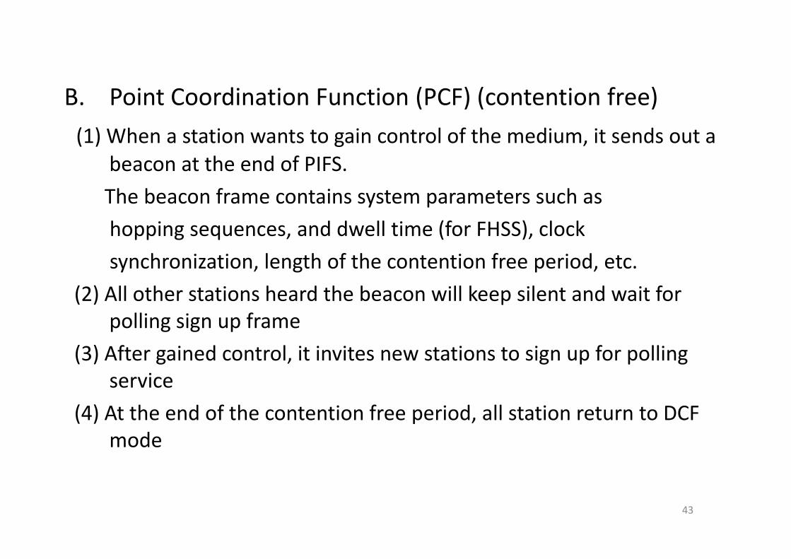
B P i C di i F i (PCF) ( i f )B. Point Coordination Function (PCF) (contention free)
(1) When a station wants to gain control of the medium, it sends out a beacon at the end of PIFS.
The beacon frame contains system parameters such as
hopping sequences, and dwell time (for FHSS), clock
synchronization, length of the contention free period, etc.
(2) All other stations heard the beacon will keep silent and wait for polling sign up frame
(3) After gained control, it invites new stations to sign up for polling service
(4) A h d f h i f i d ll i DCF(4) At the end of the contention free period, all station return to DCF mode
43

The 802.11 MAC Sublayer Protocol (3)
• To deal with the problem of noise channels, 802.11 allows frames to be fragmental into smaller pieces, each with its own checksum and ack. (using stop‐and‐wait protocol)smaller pieces, each with its own checksum and ack. (using stop and wait protocol)
44
A fragment burst.
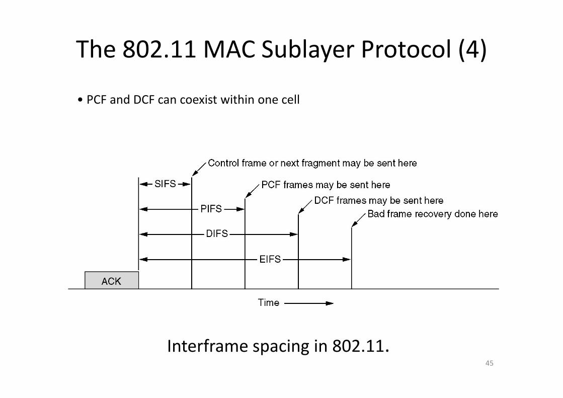
The 802.11 MAC Sublayer Protocol (4)
• PCF and DCF can coexist within one cell
45
Interframe spacing in 802.11.
The 802 11 Frame StructureThe 802.11 Frame Structure
46
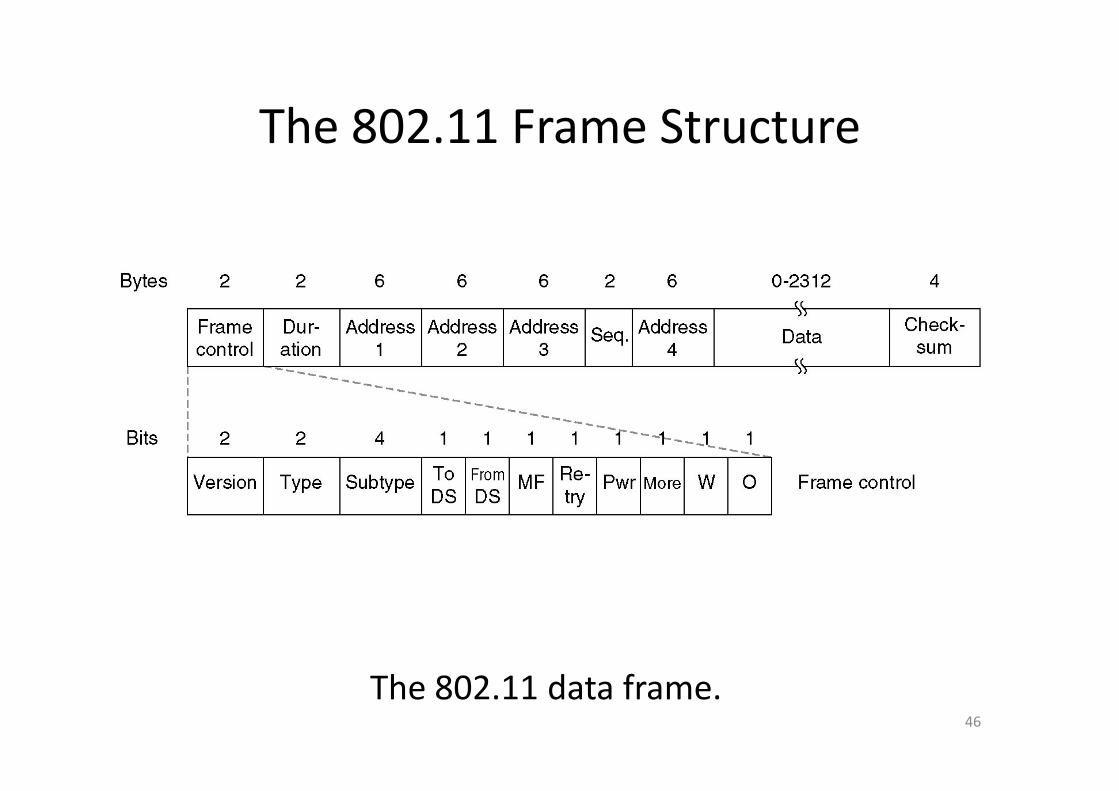
The 802.11 data frame.
Version: Protocol versionType: data, control, or managementType: data, control, or managementSubtype: RTS, CTS, ack, …To DS and from DS: to or from inter cell distribution
system (e.g. Ethernet)MF: more fragmentsRetry: retransmissionPower management: put the receiver into sleep state or
take it outMore: additional frames comingW: wired equivalent privacyO: processed strictly in orderD ti ti l th f th f d kDuration: time length of the frame and ackAddresses1.2.3 and 4: Source, destination, the source and
destination base stations for intercell traffic
47
destination base stations for intercell trafficSequence: Sequence No.
802.11 Services802.11 ServicesDistribution Services( ll b h d(managing cell membership, and interacting with station outside the cell)
• Association: To connect to a base station
• Disassociation: To disconnect from a base station
• Reassociation: To change its preferred baseReassociation: To change its preferred base station
i ib i• Distribution: How to route frames (local or intercell)
• Integration: Translation from 802.11 to other
48
gprotocol frame format
802 11 S i802.11 Services
Intracell Services
• Authentication
D h i i (l h k)• Deauthentication (leave the network)
• Privacy: managing the encryptionPrivacy: managing the encryption
and decryption
• Data Delivery
49
Data Link Layer SwitchingData Link Layer Switching
• Bridges from 802.x to 802.y
• Local Internetworking• Local Internetworking
• Spanning Tree Bridges
• Remote Bridges
R t H b B id S it h R t• Repeaters, Hubs, Bridges, Switches, Routers, Gateways
• Virtual LANs
50
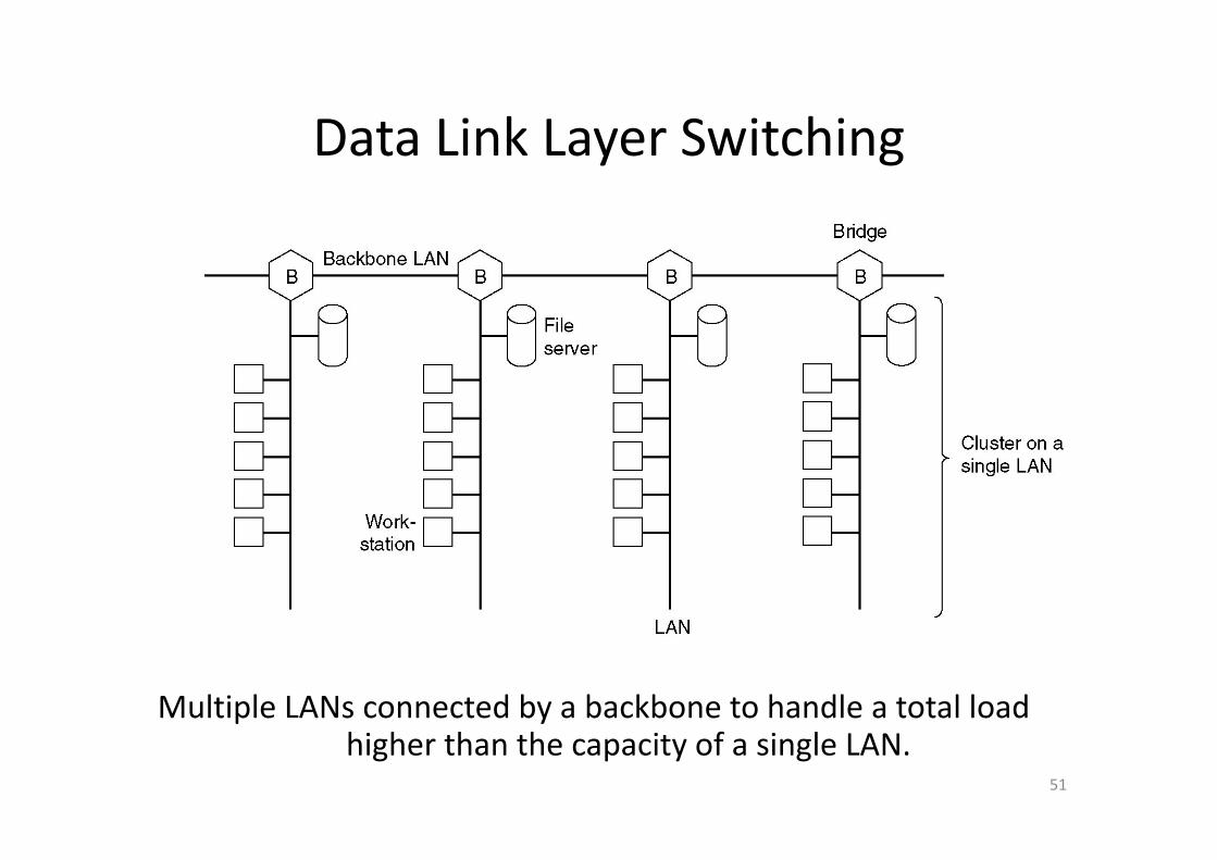
Data Link Layer SwitchingData Link Layer Switching
Multiple LANs connected by a backbone to handle a total load
51
p yhigher than the capacity of a single LAN.
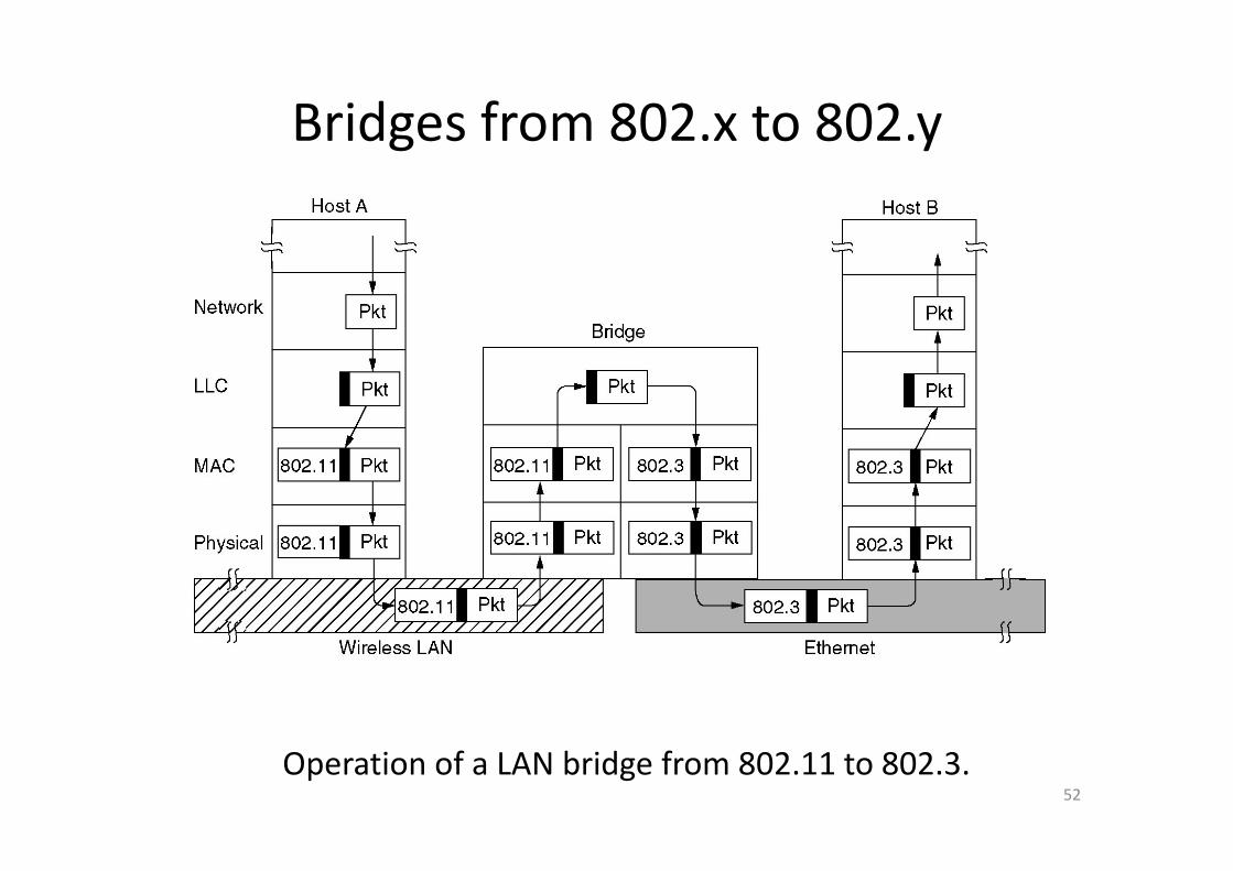
Bridges from 802.x to 802.yBridges from 802.x to 802.y
52
Operation of a LAN bridge from 802.11 to 802.3.
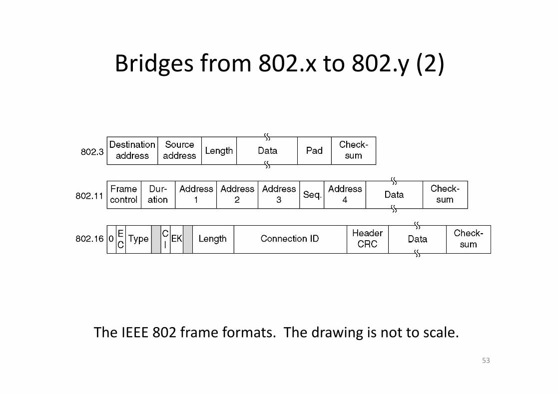
Bridges from 802 x to 802 y (2)Bridges from 802.x to 802.y (2)
The IEEE 802 frame formats The drawing is not to scale
53
The IEEE 802 frame formats. The drawing is not to scale.
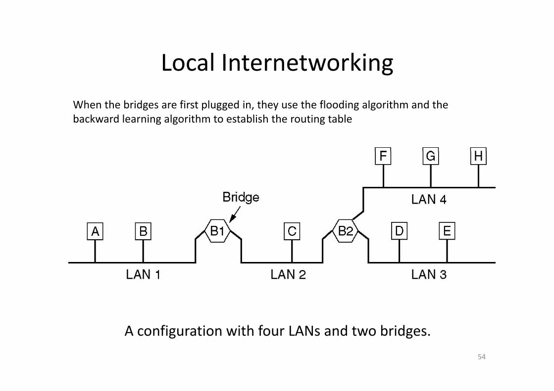
Local InternetworkingLocal InternetworkingWhen the bridges are first plugged in they use the flooding algorithm and theWhen the bridges are first plugged in, they use the flooding algorithm and the backward learning algorithm to establish the routing table
A configuration with four LANs and two bridges
54
A configuration with four LANs and two bridges.
The routing procedure of bridgesThe routing procedure of bridges
1. If destination and source LANs are the same, discard the frame
2. If the destination and source LANs are different forward the framedifferent, forward the frame
3. If the destination LAN is unknown, use flooding
55
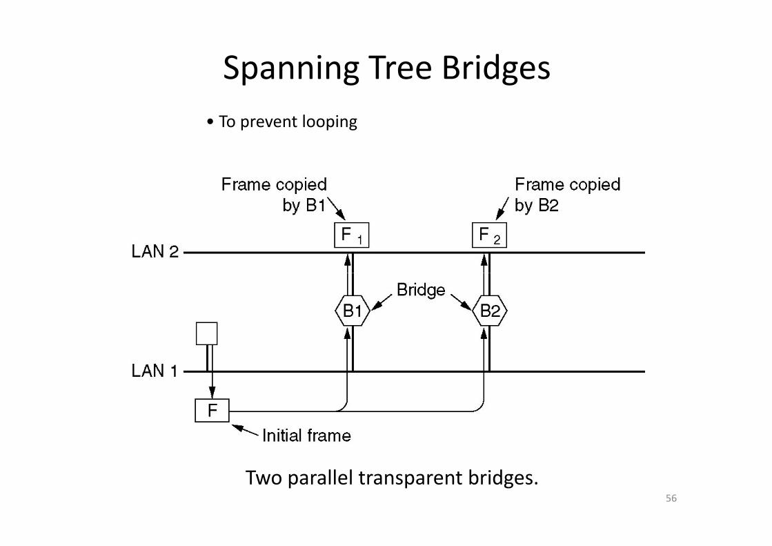
Spanning Tree Bridges• To prevent looping
56
Two parallel transparent bridges.
The procedure to establish a spanning treeThe procedure to establish a spanning tree
k h b d h l l b1. Take the bridge with lowest serial number as the root
2. Compute the shortest path from the root to ever bridge and LANto ever bridge and LAN
3. Connect these shortest paths to from a tree (no looping)
57

Spanning Tree Bridges (2)Spanning Tree Bridges (2)
(a) Interconnected LANs. (b) A spanning tree covering the LANs. Th d d li f h i
58
The dotted lines are not part of the spanning tree.
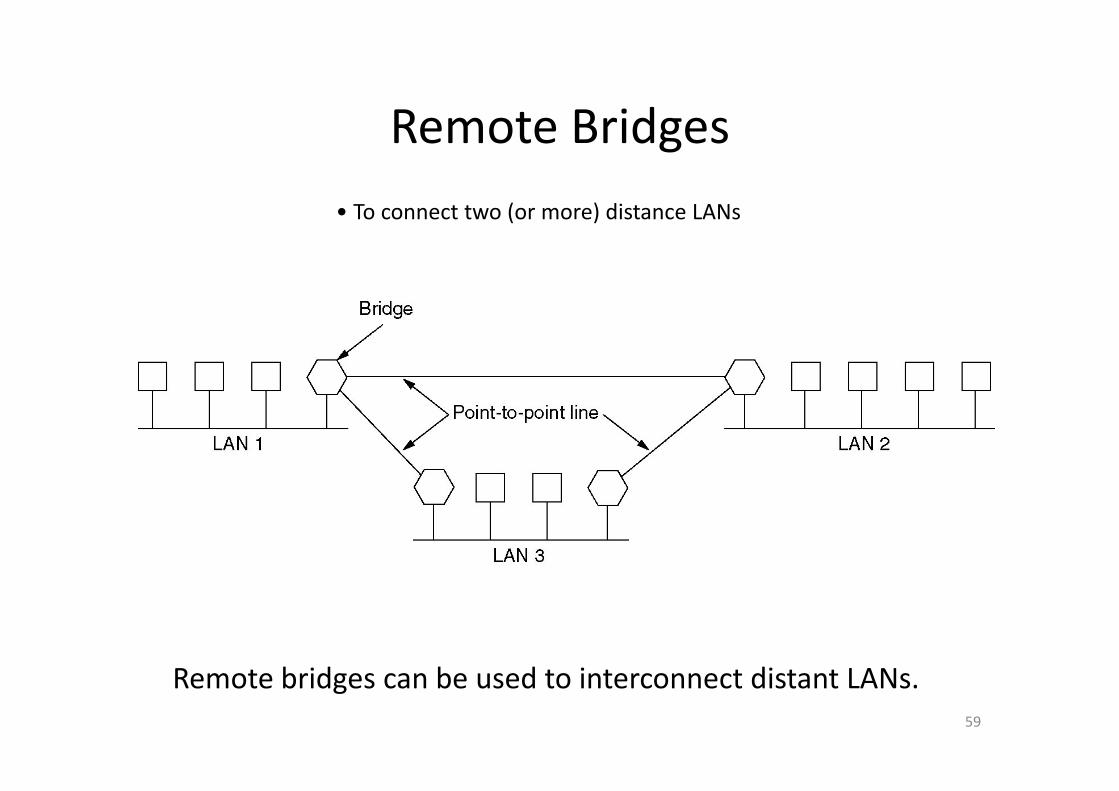
Remote BridgesRemote Bridges• To connect two (or more) distance LANs To connect two (or more) distance LANs
59
Remote bridges can be used to interconnect distant LANs.
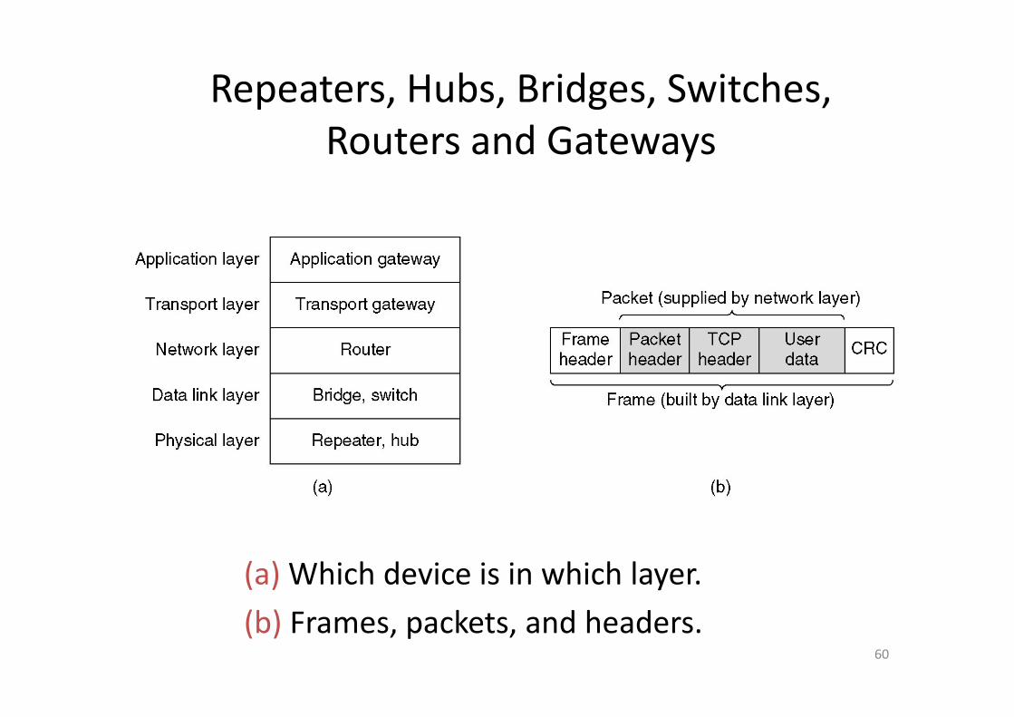
Repeaters, Hubs, Bridges, Switches, Routers and Gateways
(a) Which device is in which layer.
60
(b) Frames, packets, and headers.
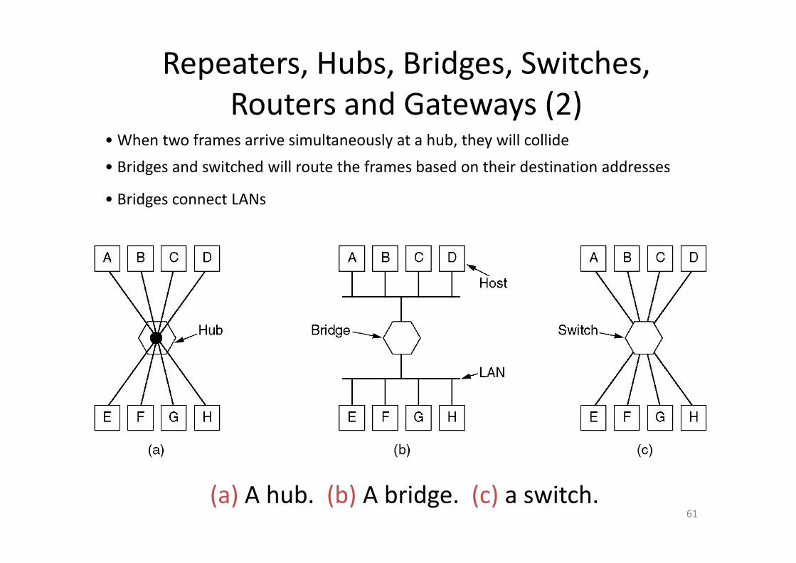
Repeaters, Hubs, Bridges, Switches, Routers and Gateways (2)
• When two frames arrive simultaneously at a hub, they will collide
• Bridges and switched will route the frames based on their destination addresses
• Bridges connect LANs
61(a) A hub. (b) A bridge. (c) a switch.
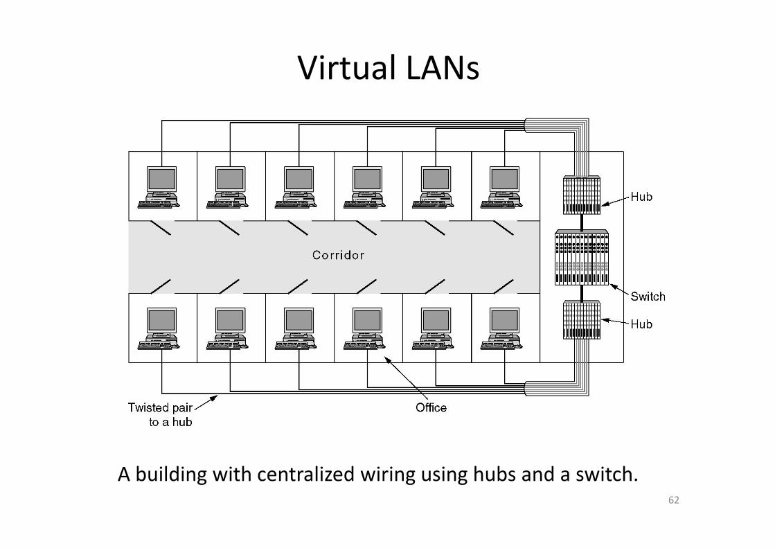
Virtual LANs
62
A building with centralized wiring using hubs and a switch.
The reasons for virtual LANsThe reasons for virtual LANs
(a) Fitting into the organization structure
(b) Loading partition(b) Loading partition
(c) Relieving broadcast storm
63

Virtual LANs (2)VLANs are based on specially‐designed VLAN‐aware switches (bridges)
(a) Four physical LANs organized into two VLANs, gray and white,
64
by two bridges. (b) The same 15 machines organized into two VLANs by switches.

Each VLAN is assigned a distinct color. Three methods are ac s ass g ed a d st ct co o ee et ods a eused to distinguish the color of an incoming frame
1 Every port is assigned a VLAN color (when a host moved1. Every port is assigned a VLAN color (when a host moved, the port must be reassigned)
2 Every MAC address is assigned a VLAN color2. Every MAC address is assigned a VLAN color
3. Every layer 3 protocol or IP address is assigned a VLAN color
(The payload must be examined by the data link layer, which violates the rule: independence of the layers. When the layer 3 protocol changed, the switch fails.)
65
There are some issues for VLANThere are some issues for VLAN
(a) What is the VLAN field format?(a) What is the VLAN field format?
(b) How to identify VLAN field?
(c) Who generates the VLAN field?
(d) What happens to frames that are already the(d) What happens to frames that are already the maximum size?
The 802 1Q will solve these problemsThe 802.1Q will solve these problems
66
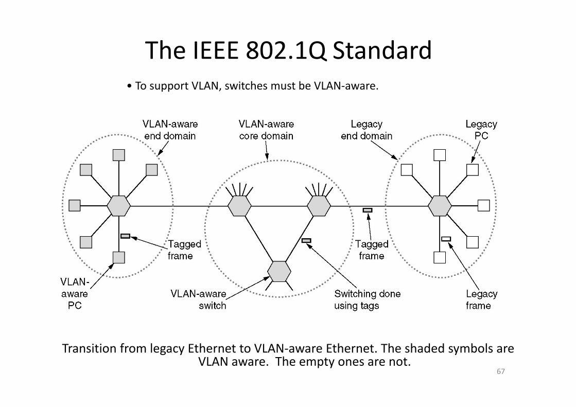
The IEEE 802.1Q Standard• To support VLAN, switches must be VLAN‐aware.
67
Transition from legacy Ethernet to VLAN‐aware Ethernet. The shaded symbols are VLAN aware. The empty ones are not.
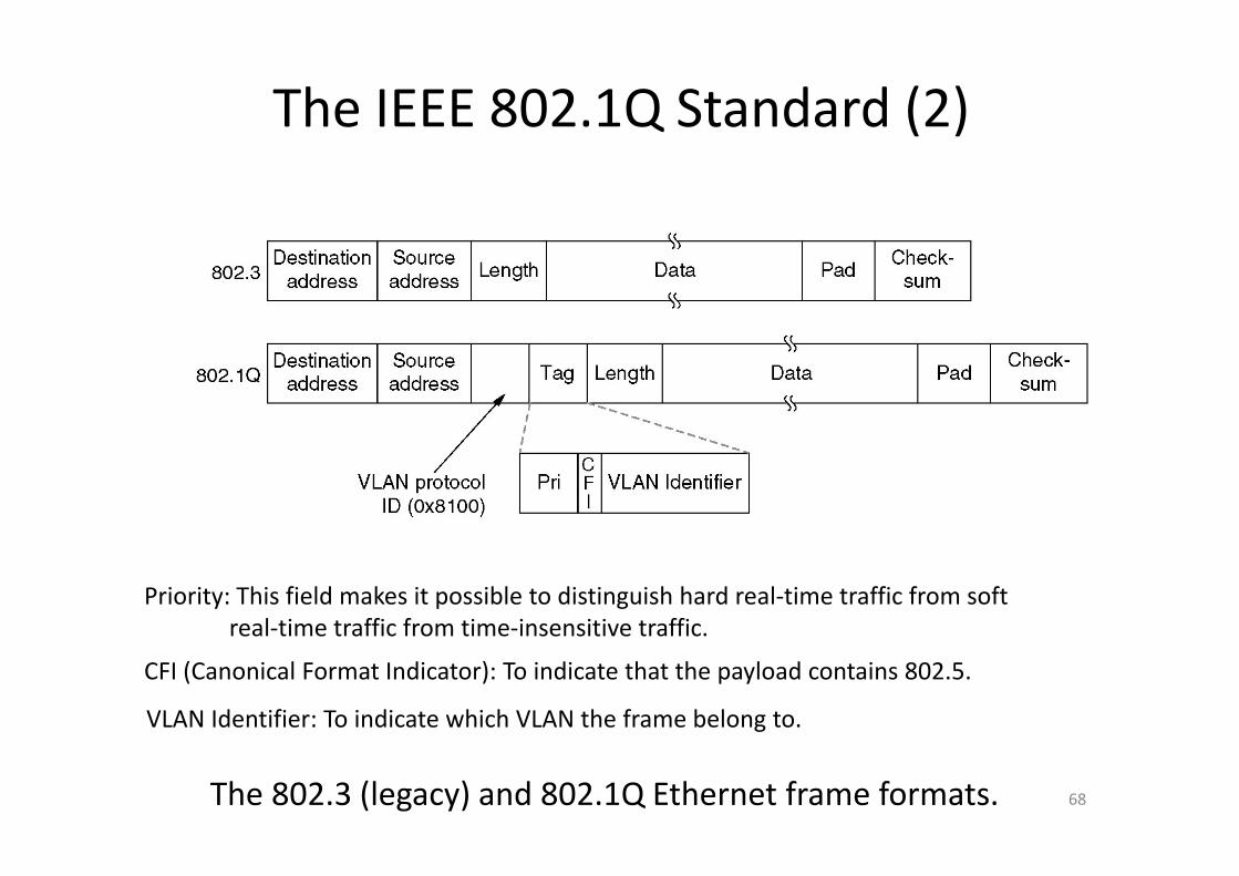
The IEEE 802.1Q Standard (2)
Priority: This field makes it possible to distinguish hard real‐time traffic from softreal‐time traffic from time‐insensitive traffic.
CFI (Canonical Format Indicator): To indicate that the payload contains 802.5.
VLAN Identifier: To indicate which VLAN the frame belong to.
68The 802.3 (legacy) and 802.1Q Ethernet frame formats.
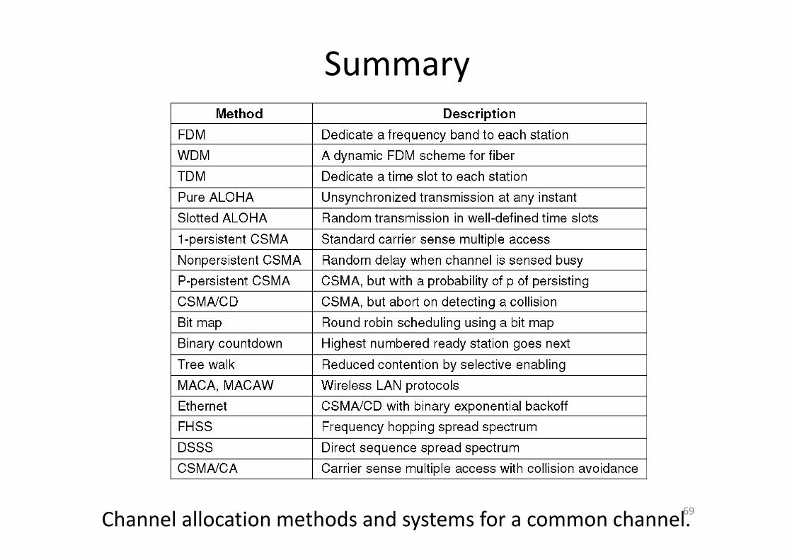
Summary
69Channel allocation methods and systems for a common channel.