Embed Size (px)
Citation preview

5/11/2018 53078408-CFD-Eurocode-2-2004 - slidepdf.com
http://slidepdf.com/reader/full/53078408-cfd-eurocode-2-2004 1/83
Berkeley, California December 2007
Concrete FrameDesign Manual
Eurocode 2-2004
For SAP2000®
and ETABS®

5/11/2018 53078408-CFD-Eurocode-2-2004 - slidepdf.com
http://slidepdf.com/reader/full/53078408-cfd-eurocode-2-2004 2/83

5/11/2018 53078408-CFD-Eurocode-2-2004 - slidepdf.com
http://slidepdf.com/reader/full/53078408-cfd-eurocode-2-2004 3/83
COPYRIGHT
Copyright© Computers and Structures, Inc., 1978-2007.All rights reserved.
The CSI Logo®, SAP2000®, and ETABS® are registered trademarks of Computers andStructures, Inc. SAFE
TMand Watch & Learn
TMare trademarks of Computers and
Structures, Inc.
The computer programs SAP2000® and ETABS® and all associated documentation areproprietary and copyrighted products. Worldwide rights of ownership rest withComputers and Structures, Inc. Unlicensed use of these programs or reproduction of documentation in any form, without prior written authorization from Computers andStructures, Inc., is explicitly prohibited.
No part of this publication may be reproduced or distributed in any form or by any means,or stored in a database or retrieval system, without the prior explicit written permission of the publisher.
Further information and copies of this documentation may be obtained from:
Computers and Structures, Inc.1995 University AvenueBerkeley, California 94704 USA
Phone: (510) 649-2200FAX: (510) 649-2299e-mail: [email protected] (for general questions)e-mail: [email protected] (for technical support questions)web: www.csiberkeley.com

5/11/2018 53078408-CFD-Eurocode-2-2004 - slidepdf.com
http://slidepdf.com/reader/full/53078408-cfd-eurocode-2-2004 4/83
3
DISCLAIMER
CONSIDERABLE TIME, EFFORT AND EXPENSE HAVE GONE INTO THEDEVELOPMENT AND DOCUMENTATION OF CSI’S PROGRAMS. THEPROGRAMS HAVE BEEN THOROUGHLY TESTED AND USED. IN USING THEPROGRAMS, HOWEVER, THE USER ACCEPTS AND UNDERSTANDS THAT NOWARRANTY IS EXPRESSED OR IMPLIED BY THE DEVELOPERS OR THEDISTRIBUTORS ON THE ACCURACY OR THE RELIABILITY OF THEPROGRAMS.
THE PROGRAMS ARE VERY PRACTICAL TOOLS FOR THE DESIGN/CHECK OFSTRUCTURES. HOWEVER THE USER MUST THOROUGHLY READ THEMANUALS AND MUST CLEARLY RECOGNIZE THE ASPECTS OF DESIGNTHAT THE PROGRAM ALGORITHMS DO NOT ADDRESS.
THE USER MUST EXPLICITLY UNDERSTAND THE ASSUMPTIONS OF THEPROGRAMS AND MUST INDEPENDENTLY VERIFY THE RESULTS.

5/11/2018 53078408-CFD-Eurocode-2-2004 - slidepdf.com
http://slidepdf.com/reader/full/53078408-cfd-eurocode-2-2004 5/83
i
Contents
Chapter 1 Introduction...........................................................1-1
1.1 Organization ...................................................................... 1-2
1.2 Recommended Reading/Practice...................................... 1-2
Chapter 2 Design Prerequisites ...........................................2-1
2.1 Design Load Combinations ............................................... 2-1
2.2 Seismic Load Effects......................................................... 2-3
2.3 Design and Check Stations............................................... 2-3
2.4 Identifying Beams and Columns ....................................... 2-3
2.5 Design of Beams ............................................................... 2-3
2.6 Design of Columns ............................................................ 2-4
2.7 P-Delta Effects................................................................... 2-5
2.8 Element Unsupported Lengths.......................................... 2-5
2.9 Choice of Input Units ......................................................... 2-6

5/11/2018 53078408-CFD-Eurocode-2-2004 - slidepdf.com
http://slidepdf.com/reader/full/53078408-cfd-eurocode-2-2004 6/83
Design Manual Concrete Frame Eurocode 2-2004
ii
Chapter 3 Design Process ....................................................3-1
3.1 Notation ............................................................................. 3-1
3.2 Assumptions / Limitations.................................................. 3-4
3.3 Design Load Combinations ............................................... 3-5
3.4 Column Design.................................................................. 3-8
3.4.1 Generation of Biaxial Interaction Surface ................ 3-9
3.4.2 Calculate Column Capacity Ratio.......................... 3-12
3.4.3 Design Longitudinal Reinforcement....................... 3-18
3.4.4 Design Column Shear Reinforcement ................... 3-18
3.5 Beam Design................................................................... 3-21
3.5.1 Design Beam Flexural Reinforcement................... 3-22
3.5.2 Design Beam Shear Reinforcement ...................... 3-30
3.5.3 Design Beam Torsion Reinforcement.................... 3-33
Chapter 4 Design Output .......................................................4-1
4.1 Overview............................................................................ 4-1
4.2 Graphical Display of Design Information........................... 4-2
4.2.1 Input/Output ............................................................ 4-2
4.3 Tabular Display of Design Output ..................................... 4-4
4.4 Member Specific Information............................................. 4-5
4.4.1 Interactive Concrete Frame Design......................... 4-8
4.5 Errors Messages and Warnings........................................ 4-9
Appendix A Second Order P-Delta Effects
Appendix B Member Unsupported Lengths and Computationof β-Factors
Appendix C Concrete Frame Design Preferences

5/11/2018 53078408-CFD-Eurocode-2-2004 - slidepdf.com
http://slidepdf.com/reader/full/53078408-cfd-eurocode-2-2004 7/83
Contents
iii
Appendix D Concrete Frame Overwrites
Appendix E Error Messages and Warnings
Appendix F Nationally Determined Parameters (NDPs)
References

5/11/2018 53078408-CFD-Eurocode-2-2004 - slidepdf.com
http://slidepdf.com/reader/full/53078408-cfd-eurocode-2-2004 8/83

5/11/2018 53078408-CFD-Eurocode-2-2004 - slidepdf.com
http://slidepdf.com/reader/full/53078408-cfd-eurocode-2-2004 9/83
1 - 1
Chapter 1Introduction
The design of concrete frames is seamlessly integrated within the program. Ini-
tiation of the design process, along with control of various design parameters,
is accomplished using the Design menu.
Automated design at the object level is available for any one of a number of
user-selected design codes, as long as the structure has first been modeled and
analyzed by the program. Model and analysis data, such as material properties
and member forces, are recovered directly from the model database, and noadditional user input is required if the design defaults are acceptable.
The design is based on a set of user-specified loading combinations. However,
the program provides default load combinations for each design code sup-
ported in SAP2000 and ETABS. If the default load combinations are accept-
able, no definition of additional load combinations is required.
In the design of columns, the program calculates the required longitudinal and
shear reinforcement. However, the user may specify the longitudinal steel, in
which case a column capacity ratio is reported. The column capacity ratio gives
an indication of the load condition with respect to the capacity of the column.
The biaxial column capacity check is based on the generation of consistent
three-dimensional interaction surfaces. It does not use any empirical formula-
tions that extrapolate uniaxial interaction curves to approximate biaxial action.

5/11/2018 53078408-CFD-Eurocode-2-2004 - slidepdf.com
http://slidepdf.com/reader/full/53078408-cfd-eurocode-2-2004 10/83
Design Manual Concrete Frame Eurocode 2-2004
1 - 2 Organization
Interaction surfaces are generated for user-specified column reinforcing con-
figurations. The column configurations may be rectangular, square, or circular,with similar reinforcing patterns. The calculation of second order moments,
unsupported lengths, and material partial factors is automated in the algorithm.
Every beam member is designed for flexure, shear, and torsion at output sta-
tions along the beam span.
Input and output data can be presented graphically on the model, in tables, or
on the calculation sheet prepared for each member. For each presentation
method, the data is in a format that allows the engineer to quickly study the
stress conditions that exist in the structure and, in the event the member rein-
forcing is not adequate, aids the engineer in taking appropriate remedial meas-
ures, including altering the design member without rerunning the entire
analysis.
1.1 Organization
This manual is designed to help you quickly become productive with the con-
crete frame design options of Eurocode 2-2004. Chapter 2 provides detailed
descriptions of the Design Prerequisites used for Eurocode 2-2004. Chapter 3
provides detailed descriptions of the code-specific process used for Eurocode
2-2004. Chapter 4 documents the design output produced by the program. The
appendices provide details on certain topics referenced in this manual.
1.2 Recommended Reading/Practice
It is strongly recommended that you read this manual and review any applica-
ble “Watch & Learn” Series™ tutorials, which are found on our website,
www.csiberkeley.com, before attempting to design a concrete frame. Addi-
tional information can be found in the on-line Help facility available from
within the program’s main menu.
5/11/2018 53078408-CFD-Eurocode-2-2004 - slidepdf.com
http://slidepdf.com/reader/full/53078408-cfd-eurocode-2-2004 11/83
2 - 1
Chapter 2Design Prerequisites
This chapter provides an overview of the basic assumptions, design precondi-
tions, and some of the design parameters that affect the design of concrete
frames.
In writing this manual it has been assumed that the user has an engineering
background in the general area of structural reinforced concrete design and
familiarity with the Eurocode 2-2004 design code.
2.1 Design Load Combinations
The design load combinations are used for determining the various combina-
tions of the load cases for which the structure needs to be designed/checked.
The load combination factors to be used vary with the selected design code.
The load combination factors are applied to the forces and moments obtained
from the associated load cases (or analysis cases for SAP2000) and are then
summed to obtain the factored design forces and moments for the load combi-
nation.
For multi-valued load combinations involving response spectrum, time history,
moving loads (only applicable for SAP2000) and multi-valued combinations
(of type enveloping, square-root of the sum of the squares or absolute) where
any correspondence between interacting quantities is lost, the program auto-
5/11/2018 53078408-CFD-Eurocode-2-2004 - slidepdf.com
http://slidepdf.com/reader/full/53078408-cfd-eurocode-2-2004 12/83
Design Manual Concrete Frame Eurocode 2-2004
2 - 2 Design Load Combinations
matically produces multiple sub combinations using maxima/minima permuta-
tions of interacting quantities. Separate combinations with negative factors forresponse spectrum cases are not required because the program automatically
takes the minima to be the negative of the maxima for response spectrum cases
and the above described permutations generate the required sub combinations.
When a design combination involves only a single multi-valued case of time
history or moving load, further options are available. The program has an op-
tion to request that time history combinations produce sub combinations for
each time step of the time history. Also, an option is available to request that
moving load combinations produce sub combinations using maxima and min-
ima of each design quantity but with corresponding values of interacting quan-
tities.
For normal loading conditions involving static dead load, live load, wind load,
and earthquake load, or dynamic response spectrum earthquake load, the pro-
gram has built-in default loading combinations for each design code. These are
based on the code recommendations and are documented for each code in the
corresponding manual.
For other loading conditions involving moving load, time history, pattern live
loads, separate consideration of roof live load, snow load, and so on, the user
must define design loading combinations either in lieu of or in addition to the
default design loading combinations.
The default load combinations assume all static load cases declared as dead
load to be additive. Similarly, all cases declared as live load are assumed addi-
tive. However, each static load case declared as wind or earthquake, or re-
sponse spectrum cases, is assumed to be non additive with each other and
produces multiple lateral load combinations. Also, wind and static earthquake
cases produce separate loading combinations with the sense (positive or nega-
tive) reversed. If these conditions are not correct, the user must provide the ap-
propriate design combinations.
The default load combinations are included in the design if the user requests
them to be included or if no other user-defined combinations are available forconcrete design. If any default combination is included in design, all default
combinations will automatically be updated by the program any time the de-
sign code is changed or if static or response spectrum load cases are modified.

5/11/2018 53078408-CFD-Eurocode-2-2004 - slidepdf.com
http://slidepdf.com/reader/full/53078408-cfd-eurocode-2-2004 13/83
Design Prerequisites - Design Prerequisites
Seismic Load Effects 2 - 3
Live load reduction factors can be applied to the member forces of the live load
case on an element-by-element basis to reduce the contribution of the live loadto the factored loading.
The user is cautioned that if moving load or time history results are not re-
quested to be recovered in the analysis for some or all of the frame members,
the effects of those loads will be assumed to be zero in any combination that
includes them.
2.2 Seismic Load Effects
Seismic design requirements in accordance with Eurocode 8 currently are not
addressed in the concrete frame design to Eurocode 2-2004. This capabilitywill be added in a future version.
2.3 Design and Check Stations
For each load combination, each element is designed or checked at a number of
locations along the length of the element. The locations are based on equally
spaced output stations along the clear length of the element. The number of
output stations in an element is requested by the user before the analysis is per-
formed. The user can refine the design along the length of an element by re-
questing more output stations.
2.4 Identifying Beams and Columns
In the program, all beams and columns are represented as frame elements, but
design of beams and columns requires separate treatment. Identification for a
concrete element is accomplished by specifying the frame section assigned to
the element to be of type beam or column. If any brace member exists in the
frame, the brace member also would be identified as a beam or a column ele-
ment, depending on the section assigned to the brace member.

5/11/2018 53078408-CFD-Eurocode-2-2004 - slidepdf.com
http://slidepdf.com/reader/full/53078408-cfd-eurocode-2-2004 14/83
Design Manual Concrete Frame Eurocode 2-2004
2 - 4 Design of Beams
2.5 Design of Beams
In the design of concrete beams, in general, the program calculates and reports
the required areas of reinforcing steel for flexure, shear, and torsion based on
the beam moments, shears, load combination factors, and other criteria, which
are described in detail in the code-specific manual. The reinforcement re-
quirements are calculated at a user-defined number of stations along the beam
span.
All the beams are designed for major direction flexure, shear, and torsion only.
Effects due to any axial forces and minor direction bending that may exist in
the beams must be investigated independently by the user.
In designing the flexural reinforcement for the major moment at a particular
station of a particular beam, the steps involve the determination of the maxi-
mum factored moments and the determination of the reinforcing steel. The
beam section is designed for the maximum positive and maximum negative
factored moment envelopes obtained from all of the load combinations. Nega-
tive beam moments produce top steel. In such cases, the beam is always de-
signed as a rectangular section. Positive beam moments produce bottom steel.
In such cases, the beam may be designed as a rectangular beam or a T-beam.
For the design of flexural reinforcement, the beam is first designed as a singly
reinforced beam. If the singly reinforced beam is not adequate, the required
compression reinforcement is calculated.
In designing the shear reinforcement for a particular beam for a particular set
of loading combinations at a particular station due to the beam major shear, the
steps involve the determination of the factored shear force, the determination
of the shear force that can be resisted by concrete, and the determination of any
reinforcement steel required to carry the balance.
2.6 Design of Columns
In the design of the columns, the program calculates the required longitudinal
steel, or if the longitudinal steel is specified, the column stress condition is re-ported in terms of a column capacity ratio, which is a factor that gives an indi-
cation of the load condition of the column with respect to the capacity of the

5/11/2018 53078408-CFD-Eurocode-2-2004 - slidepdf.com
http://slidepdf.com/reader/full/53078408-cfd-eurocode-2-2004 15/83
Design Prerequisites - Design Prerequisites
P-Delta Effects 2 - 5
column. The design procedure for the reinforced concrete columns of the
structure involves the following steps:
Generate axial force-biaxial moment interaction surfaces for all of the dif-
ferent concrete section types in the model.
Check the capacity of each column for the factored axial force and bending
moments obtained from each loading combination at each end of the col-
umn. This step is also used to calculate the required steel reinforcement (if
none was specified) that will produce a column capacity ratio of 1.0.
The generation of the interaction surface is based on the assumed strain and
stress distributions and other simplifying assumptions. These stress and strain
distributions and the assumptions are documented in Chapter 3.
The shear reinforcement design procedure for columns is very similar to that
for beams, except that the effect of the axial force on the concrete shear capac-
ity is considered.
2.7 P-Delta Effects
The program design process requires that the analysis results include P-delta
effects. For the individual member stability effects, the first order analysis
moments are increased with additional second order moments, as documentedin Chapter 3. As an alternative, the user can turn off the calculation of second
order moments for individual member stability effects. If this is done, the user
should use another method, such as equivalent lateral loading or P-delta analy-
sis with vertical members divided into at least two segments, to capture the
member stability effects in addition to the global P-delta effects.
Users of the program should be aware that the default analysis option is turned
OFF for P-delta effect. The user can turn the P-delta analysis ON and set the
maximum number of iterations for the analysis. The default number of iteration
for P-delta analysis is 1. Further details about P-delta analysis are provided in
Appendix A of this design manual.

5/11/2018 53078408-CFD-Eurocode-2-2004 - slidepdf.com
http://slidepdf.com/reader/full/53078408-cfd-eurocode-2-2004 16/83
Design Manual Concrete Frame Eurocode 2-2004
2 - 6 Element Unsupported Lengths
2.8 Element Unsupported Lengths
To account for column slenderness effects, the column unsupported lengths are
required. The two unsupported lengths are l33
and l22
. These are the lengths be-
tween support points of the element in the corresponding directions. The length
l33
corresponds to instability about the 3-3 axis (major axis), andl22
corresponds
to instability about the 2-2 axis (minor axis).
Normally, the unsupported element length is equal to the length of the element,
i.e., the distance between END-I and END-J of the element. The program,
however, allows users to assign several elements to be treated as a single
member for design. This can be accomplished differently for major and minor
bending, as documented in Appendix B.
The user has options to specify the unsupported lengths of the elements on an
element-by-element basis.
2.9 Choice of Input Units
Imperial, as well as SI and MKS metric units can be used for input and output.
The codes are based on a specific system of units. All equations and descrip-
tions presented in the subsequent chapters correspond to that specific system of
units unless otherwise noted. The Eurocode 2-2004 design code is published in
Newton-millimeter-second units and all equations and descriptions presentedin the “Design Process” chapter correspond to these units. However, any sys-
tem of units can be used to define and design a structure in the program.
5/11/2018 53078408-CFD-Eurocode-2-2004 - slidepdf.com
http://slidepdf.com/reader/full/53078408-cfd-eurocode-2-2004 17/83
3 - 1
Chapter 3 Design Process
This chapter provides a detailed description of the code-specific algorithms
used in the design of concrete frames when the Eurocode 2-2004 code has been
selected. For simplicity, all equations and descriptions presented in this chapter
correspond to Newton-millimeter-second units unless otherwise noted. It also
should be noted that this section describes the implementation of the CEN De-
fault version of Eurocode 2-2004, without a country specific National Annex.
Where Nationally Determined Parameters [NDPs] are to be considered, this ishighlighted in the respective section by the notation [NDP]. A listing of coun-
try specific NDPs is included in Appendix F.
3.1 Notation
The various notations used in this chapter are described herein:
Ac Area of concrete used to determine shear stress, mm2
Ag Gross area of concrete, mm2
Ak Area enclosed by centerlines of connecting walls for torsion, mm2
As Area of tension reinforcement, mm2

5/11/2018 53078408-CFD-Eurocode-2-2004 - slidepdf.com
http://slidepdf.com/reader/full/53078408-cfd-eurocode-2-2004 18/83
Design Manual Concrete Frame Eurocode 2-2004
3 - 2 Notation
A′ s Area of compression reinforcement, mm2
Asl Area of longitudinal torsion reinforcement, mm2
At /s Area of transverse torsion reinforcement (closed stirrups) per unitlength of the member, mm
2 /mm
Asw /s Area of shear reinforcement per unit length of the member,mm
2 /mm
E c Modulus of elasticity of concrete, MPa
E s Modulus of elasticity of reinforcement, assumed as 200 GPa
I g Moment of inertia of gross concrete section about centroidal axis,neglecting reinforcement, mm
4
M 01 Smaller factored end moment in a column, N-mm
M 02 Larger factored end moment in a column, N-mm
M Ed Design moment, including second order effects to be used in de-sign, N-mm
M 0Ed Equivalent first order end moment (EC2 5.8.8.2), N-mm
M 2 Second order moment from the Nominal Curvature method (EC25.8.8), N-mm
M 22 First order factored moment at a section about 2-axis, N-mm
M 33 First order factored moment at a section about 3-axis, N-mm
N B Buckling load, N
N Ed Factored axial load at a section, N
T Ed Factored torsion at a section, N-mm
V Ed Factored shear force at a section, N
V Rd,c Design shear resistance without shear reinforcement, N
V Rd,max Shear force that can be carried without crushing of the notionalconcrete compressive struts, N
a Depth of compression block, mm
amax Maximum allowed depth of compression block, mm
5/11/2018 53078408-CFD-Eurocode-2-2004 - slidepdf.com
http://slidepdf.com/reader/full/53078408-cfd-eurocode-2-2004 19/83
Chapter 3 - Design Process
Notation 3 - 3
b Width of member, mm
b f Effective width of flange (T-beam section), mm
bw Width of web (T-beam section), mm
d Distance from compression face to tension reinforcement, mm
d ′ Concrete cover to center of reinforcing, mm
d s Thickness of slab/flange (T-beam section), mm
e2 Deflection due to curvature for the Nominal Curvature method(EC2 5.8.8), mm
ei Eccentricity to account for geometric imperfections (EC2 5.2),
mm
emin Minimum eccentricity (EC2 6.1), mm
f cd Design concrete compressive strength (EC 3.1.6), MPa
f ctm Mean value of axial tensile strength of concrete, MPa
f yd Design yield strength of reinforcement (EC2 3.2), MPa
h Overall depth of a column section, mm
l0 Member effective length, mm
lu Member unsupported length, mm
r Radius of gyration of column section, mm
t ef Effective wall thickness for torsion, mm
u Outer perimeter of cross-section, mm
uk Outer perimeter of area Ak , mm
x Depth to neutral axis, mm
αcc Material coefficient taking account of long term effects on thecompressive strength (EC2 3.1.6)
αct Material coefficient taking account of long term effects on thetensile strength (EC2 3.1.6)
αlcc Light-weight material coefficient taking account of long termeffects on the compressive strength (EC2 11.3.5)

5/11/2018 53078408-CFD-Eurocode-2-2004 - slidepdf.com
http://slidepdf.com/reader/full/53078408-cfd-eurocode-2-2004 20/83
Design Manual Concrete Frame Eurocode 2-2004
3 - 4 Assumptions / Limitations
αlct Light-weight material coefficient taking account of long termeffects on the tensile strength (EC2 11.3.5)
ε c Strain in concrete
ε cu2 Ultimate strain allowed in extreme concrete fiber (0.0035mm/mm)
ε s Strain in reinforcing steel
γ c Material partial factor for concrete (EC2 2.4.2.4)
γ s Material partial factor for steel (EC2 2.4.2.4)
λ Factor defining effective height of concrete stress block (EC23.1.7)
η Factor defining effective strength of concrete stress block (EC23.1.7)
θ Angle between concrete compression strut and member axisperpendicular to the shear force
θ i Inclination due to geometric imperfections (EC2 5.2), ratio
θ 0 Basic inclination for geometric imperfections (EC2 5.2), ratio
3.2 Assumptions / Limitations
The following general assumptions and limitations exist for the current imple-
mentation of Eurocode 2-2004 within the program. Limitations related to
specific parts of the design are discussed in their relevant sections.
Seismic design requirements to Eurocode 8 currently are not handled.
Design of plain or lightly reinforced concrete sections is not handled.
Design of prestressed or post-tensioned sections currently is not handled.
The serviceability limit state currently is not handled.
Design for fire resistance currently is not handled.
5/11/2018 53078408-CFD-Eurocode-2-2004 - slidepdf.com
http://slidepdf.com/reader/full/53078408-cfd-eurocode-2-2004 21/83
Chapter 3 - Design Process
Design Load Combinations 3 - 5
By default, the Persistent & Transient design situation (EC2 Table 2.1N) is
considered. Other design situations can be considered and may requiremodification of some of the concrete design preference values.
It is assumed that the structure being designed is a building type structure.
Special design requirements for special structure types (such as bridges,
pressure vessels, offshore platforms, liquid-retaining structures, etc,) cur-
rently are not handled.
It is assumed that the load actions are based on Eurocode 1.
The program works with cylinder strength as opposed to cube strength.
The program does not check depth to width ratios (EC2 5.3.1) or effectiveflange widths for T-beams (EC2 5.3.2). The user needs to consider these
items when defining the sections.
It is assumed that the user will consider the maximum concrete strength
limit, C max
, specified in the design code (EC2 3.1.2(3)).
It is assumed that the cover distances input by the user satisfy the minimum
cover requirements (EC2 4.4.1.2).
The design value of the modulus of elasticity of steel reinforcement, E s, is
assumed to be 200 GPa (EC2 3.2.7(4)).
3.3 Design Load Combinations
The design load combinations are the various combinations of the prescribed
response cases for which the structure is to be checked. The program creates a
number of default design load combinations for a concrete frame design. Users
can add their own design load combinations as well as modify or delete the
program default design load combinations. An unlimited number of design
load combinations can be specified.
To define a design load combination, simply specify one or more response
cases, each with its own scale factor. The scale factors are applied to the forces
and moments from the analysis cases to form the design forces and moments
for each design load combination. There is one exception to the preceding. For
spectral analysis modal combinations, any correspondence between the signs
5/11/2018 53078408-CFD-Eurocode-2-2004 - slidepdf.com
http://slidepdf.com/reader/full/53078408-cfd-eurocode-2-2004 22/83
Design Manual Concrete Frame Eurocode 2-2004
3 - 6 Design Load Combinations
of the moments and axial loads is lost. The program uses eight design load
combinations for each such loading combination specified, reversing the signof axial loads and moments in major and minor directions.
As an example, if a structure is subjected to dead load, D, and live load, L,
only, the Eurocode 2-2004 design check would require two design load com-
binations only. However, if the structure is subjected to wind, earthquake, or
other loads, numerous additional design load combinations may be required.
The program allows live load reduction factors to be applied to the member
forces of the reducible live load case on a member-by-member basis to reduce
the contribution of the live load to the factored responses.
The design load combinations are the various combinations of the analysiscases for which the structure needs to be checked. Eurocode 0-2002 allows
load combinations to be defined based on either EC0 Eq. 6.10 or the less
favorable of EC0 Eqs. 6.10a and 6.10b [NDP].
∑ ∑≥ >
+++1 1
,,0,1,1,,,
j i
ik iiQk QP jk jG QQPG ψ γ γ γ γ (EC0 Eq. 6.10)
∑ ∑≥ >
+++1 1
,,0,1,1,01,,,
j i
ik iiQk QP jk jG QQPG ψ γ ψ γ γ γ (EC0 Eq. 6.10a)
∑ ∑≥ >
+++1 1
,,0,1,1,,,
j i
ik iiQk QP jk jG j QQPG ψ γ γ γ γ ξ (EC0 Eq. 6.10b)
Load combinations considering seismic loading are automatically generated
based on EC0 Eq. 6.12b.
∑ ∑≥ >
+++1 1
,,2,
j i
ik i Ed jk Q APG ψ (EC0 Eq. 6.12b)
For this code, if a structure is subjected to dead load (D), live load (L), wind
(W), and earthquake (E) loads, and considering that wind and earthquake
forces are reversible, the following load combinations need to be considered if
equation 6.10 is specified for generation of the load combinations (EC0 6.4.3):
γGj,sup
D (EC0 Eq. 6.10)
γGj,sup
D + γQ,1
L (EC0 Eq. 6.10)
5/11/2018 53078408-CFD-Eurocode-2-2004 - slidepdf.com
http://slidepdf.com/reader/full/53078408-cfd-eurocode-2-2004 23/83
Chapter 3 - Design Process
Design Load Combinations 3 - 7
γGj,inf D ± γ
Q,1 WγGj,sup
D ± γQ,1
W
(EC0 Eq. 6.10)(EC0 Eq. 6.10)
γGj,sup
D + γQ,1
L ± γQ,i
ψ0,i
W
γGj,sup
D ± γQ,1
W + γQ,i
ψ0,i
L
(EC0 Eq. 6.10)(EC0 Eq. 6.10)
D ± 1.0E
D ± 1.0E + ψ2,i
L
(EC0 Eq. 6.12b)
If the load combinations are specified to be generated from the max of EC0
Eqs. 6.10a and 6.10b, the following load combinations from both equations are
considered in the program.
γGj,sup
D
ξ γGj,sup
D
(EC0 Eq. 6.10a)(EC0 Eq. 6.10b)
γGj,sup
D + γQ,1
ψ0,1
L
ξ γGj,sup
D + γQ,1
L
(EC0 Eq. 6.10a)(EC0 Eq. 6.10b)
γGj,inf
D ± γQ,1
ψ0,1
W
γGj,sup
D ± γQ,1
ψ0,1
W
γGj,inf
D ± γQ,1
W
ξ γGj,sup D ± γ
Q,1 W
(EC0 Eq. 6.10a)(EC0 Eq. 6.10a)(EC0 Eq. 6.10b)(EC0 Eq. 6.10b)
γGj,sup
D + γQ,1
ψ0,1
L ± γQ,i
ψ0,i
W
γGj,sup
D ± γQ,1
ψ0,1
W + γQ,i
ψ0,i
L
ξ γGj,sup
D + γQ,1
L ± γQ,i
ψ0,i
W
γGj,sup
D ± γQ,1
W + γQ,i
ψ0,i
L
(EC0 Eq. 6.10a)(EC0 Eq. 6.10a)(EC0 Eq. 6.10b)(EC0 Eq. 6.10b)
D ± 1.0E
D ± 1.0E + ψ2,i
L
(EC0 Eq. 6.12b)
For both sets of load combinations, the variable values for the CEN Default
version of the load combinations are defined in the list that follows. Values forother countries, as determined from their National Annex are included in Ap-
pendix F.
γGj,sup
= 1.35 (EC0 Table A1.2(B))
5/11/2018 53078408-CFD-Eurocode-2-2004 - slidepdf.com
http://slidepdf.com/reader/full/53078408-cfd-eurocode-2-2004 24/83
Design Manual Concrete Frame Eurocode 2-2004
3 - 8 Column Design
γGj,inf
= 1.00 (EC0 Table A1.2(B))
γQ,1= 1.5 (EC0 Table A1.2(B))
ψ0,i
= 0.7 (live load, assumed not to be storage) (EC0 Table A1.1)
ψ0,i
= 0.6 (wind load) (EC0 Table A1.1)
ξ = 0.85 (EC0 Table A1.2(B))
ψ2,i
= 0.3 (assumed to be office/residential space) (EC0 Table A1.1)
Depending on the selection made in the design preferences, one of the preced-
ing two sets of load combinations also makes up the default design load com-
binations in the program whenever the Eurocode 2-2004 design code is used.The user should use other appropriate design load combinations if roof live
load is separately treated, or if other types of loads are present. PLL is the live
load multiplied by the Pattern Live Load Factor. The Pattern Live Load Factor
can be specified in the Preferences.
When using the Eurocode 2-2004 design code, the program design assumes
that a P-delta analysis has been performed.
3.4 Column Design
The program can be used to check column capacity or to design columns. If the
geometry of the reinforcing bar configuration of the concrete column section
has been defined, the program can check the column capacity. Alternatively,
the program can calculate the amount of reinforcing required to design the
column based on a provided reinforcing bar configuration. The reinforcement
requirements are calculated or checked at a user-defined number of output sta-
tions along the column height. The design procedure for reinforced concrete
columns involves the following steps:
Generate axial force-biaxial moment interaction surfaces for all of the dif-
ferent concrete section types of the model. A typical biaxial interaction
diagram is shown in Figure 3-1. For reinforcement to be designed, the pro-
gram generates the interaction surfaces for the range of allowable rein-
forcement from a minimum of 0.2 percent [NDP] to a maximum of 4
percent [NDP] (EC2 9.5.2).

5/11/2018 53078408-CFD-Eurocode-2-2004 - slidepdf.com
http://slidepdf.com/reader/full/53078408-cfd-eurocode-2-2004 25/83
Chapter 3 - Design Process
Column Design 3 - 9
Calculate the capacity ratio or the required reinforcement area for the fac-
tored axial force and biaxial (or uniaxial) bending moments obtained fromeach load combination at each output station of the column. The target ca-
pacity ratio is taken as the Utilization Factor Limit when calculating the
required reinforcing area.
Design the column shear reinforcement.
The following four sections describe in detail the algorithms associated with
this process.
3.4.1 Generation of Biaxial Interaction Surfaces
The column capacity interaction volume is numerically described by a series of
discrete points that are generated on the three-dimensional interaction failure
surface. In addition to axial compression and biaxial bending, the formulation
allows for axial tension and biaxial bending considerations. A typical interac-
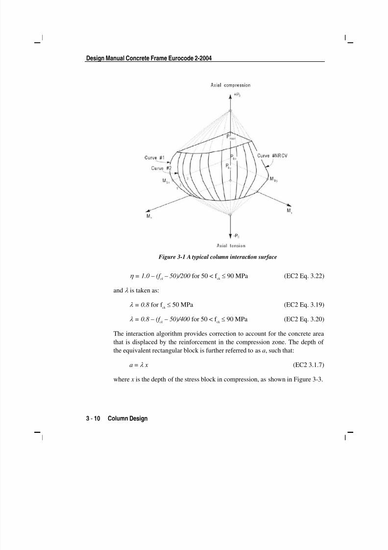
tion surface is shown in Figure 3-1.
The coordinates of the points on the failure surface are determined by rotating
a plane of linear strain in three dimensions on the column section, as shown in
Figure 3-2. The linear strain diagram limits the maximum concrete strain, εc, at
the extremity of the section to 0.0035 (EC2 Table 3.1).
The formulation is based consistently upon the general principles of ultimatestrength design (EC2 6.1).
The stress in the steel is given by the product of the steel strain and the steel
modulus of elasticity, ε s E s, and is limited to the yield stress of the steel, f yd (EC2
3.2.7). The area associated with each reinforcing bar is assumed to be placed at
the actual location of the center of the bar, and the algorithm does not assume
any further simplifications with respect to distributing the area of steel over the
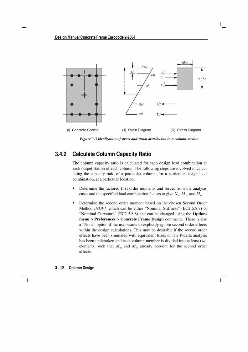
cross-section of the column, as shown in Figure 3-2.
The concrete compression stress block is assumed to be rectangular, with an
effective strength of η f cd
(EC2 3.1.7) and effective height of λ x, as shown in
Figure 3-3, where η is taken as:
η = 1.0 for f ck ≤ 50 MPa (EC2 Eq. 3.21)
5/11/2018 53078408-CFD-Eurocode-2-2004 - slidepdf.com
http://slidepdf.com/reader/full/53078408-cfd-eurocode-2-2004 26/83
Design Manual Concrete Frame Eurocode 2-2004
3 - 10 Column Design
Figure 3-1 A typical column interaction surface
η = 1.0 – (f ck – 50)/200 for 50 < f ck ≤ 90 MPa (EC2 Eq. 3.22)
and λ is taken as:
λ = 0.8 for f ck ≤ 50 MPa (EC2 Eq. 3.19)
λ = 0.8 – (f ck
– 50)/400 for 50 < f ck ≤ 90 MPa (EC2 Eq. 3.20)
The interaction algorithm provides correction to account for the concrete area
that is displaced by the reinforcement in the compression zone. The depth of
the equivalent rectangular block is further referred to as a, such that:
a = λ x (EC2 3.1.7)
where x is the depth of the stress block in compression, as shown in Figure 3-3.

5/11/2018 53078408-CFD-Eurocode-2-2004 - slidepdf.com
http://slidepdf.com/reader/full/53078408-cfd-eurocode-2-2004 27/83
Chapter 3 - Design Process
Column Design 3 - 11
ε c
ε c
ε c
ε c
ε c
ε c
ε c
ε c
ε c
ε c
Figure 3-2 Idealized strain distribution for generation of interaction surface
The effect of the material partial factors, γ c
and γ s [NDPs], and the material co-
efficients, α cc, α
ct , α
lcc, and α
lct [NDPs], are included in the generation of the in-
teraction surface (EC2 3.1.6).
Default values for γ c, γ
s, α
cc, α
ct , α
lcc, and α
lct are provided by the program but
can be overwritten using the Options menu > Preferences > Concrete Frame
Design command.
5/11/2018 53078408-CFD-Eurocode-2-2004 - slidepdf.com
http://slidepdf.com/reader/full/53078408-cfd-eurocode-2-2004 28/83
Design Manual Concrete Frame Eurocode 2-2004
3 - 12 Column Design
c
d'
C a = x l
2sC
1sC
hfcd
ecu3
es4
es3
es2
es1
Ts4
Ts3
(i) Concrete Section (ii) Strain Diagram (iii) Stress Diagram
Figure 3-3 Idealization of stress and strain distribution in a column section
3.4.2 Calculate Column Capacity Ratio
The column capacity ratio is calculated for each design load combination at
each output station of each column. The following steps are involved in calcu-
lating the capacity ratio of a particular column, for a particular design loadcombination, at a particular location:
Determine the factored first order moments and forces from the analysis
cases and the specified load combination factors to give N ed , M
22, and M
33.
Determine the second order moment based on the chosen Second Order
Method [NDP], which can be either “Nominal Stiffness” (EC2 5.8.7) or
“Nominal Curvature” (EC2 5.8.8) and can be changed using the Options
menu > Preferences > Concrete Frame Design command. There is also
a “None” option if the user wants to explicitly ignore second order effects
within the design calculations. This may be desirable if the second order
effects have been simulated with equivalent loads or if a P-delta analysishas been undertaken and each column member is divided into at least two
elements, such that M 22
and M 33
already account for the second order
effects.
5/11/2018 53078408-CFD-Eurocode-2-2004 - slidepdf.com
http://slidepdf.com/reader/full/53078408-cfd-eurocode-2-2004 29/83
Chapter 3 - Design Process
Column Design 3 - 13
Add the second order moments to the first order moments if the column is
determined to be slender (EC2 5.8.3.1). Determine whether the point, de-fined by the resulting axial load and biaxial moment set, lies within the in-
teraction volume.
The following three sections describe in detail the algorithms associated with
this process.
3.4.2.1 Determine Factored Moments and Forces
The loads for a particular design load combination are obtained by applying the
corresponding factors to all of the analysis cases, giving N Ed
, M 22
, and M 33
.
These first order factored moments are further increased to account for geo-metric imperfections (EC2 5.2). The eccentricity to account for geometric im-
perfections, ei, is defined as:
ei= θ
il
0 /2 (EC2 Eq. 5.2)
where l0
is the effective length of the member and θ iis an inclination, defined
as a ratio as:
θ i= θ
0 α
h α
m(EC2 Eq. 5.1)
where α m
is a reduction factor for the number of members, taken as 1 in the
program for isolated members, α h is a reduction factor for length, taken as2/ ,l and θ
0 [NDP] is the basic inclination, defined as a ratio, and can be
overwritten using the Options menu > Preferences > Concrete Frame De-
sign command. The resulting first order moments, including geometric imper-
fections, are calculated as:
M 22
= M 22
+ ei2
N Ed
M 33
= M 33
+ ei3
N Ed
where ei
shall be taken greater than or equal to the code specified minimum
eccentricity emin
(EC2 6.2). The minimum eccentricity, emin
, is defined as:
emin
= h/30 ≥ 20mm (EC2 6.1)
The moment generated due to the geometric imperfection eccentricity, or the
min eccentricity if greater, is only considered in a single direction at a time.
5/11/2018 53078408-CFD-Eurocode-2-2004 - slidepdf.com
http://slidepdf.com/reader/full/53078408-cfd-eurocode-2-2004 30/83
Design Manual Concrete Frame Eurocode 2-2004
3 - 14 Column Design
3.4.2.2 Second Order Moments
The design algorithm assumes that the moments M 22
and M 32
are obtained from
a second order elastic (P-Δ) analysis or by applying fictitious, magnified hori-
zontal forces following the recommendations of EC2 Annex H. For more in-
formation about P-Δ analysis, refer to Appendix A.
The computed moments are further increased for individual column stability
effects, P-δ (EC2 5.8.5), by either computing a moment magnification factor
based on the Nominal Stiffness method (EC2 5.8.7) or computing a nominal
second order moment based on the Nominal Curvature method (EC2 5.8.8).
3.4.2.2.1 Nominal Stiffness Method The overall design moment, M
Ed , based on the Nominal Stiffness method is
computed as:
M Ed
= M 0Ed
(factor) (EC2 Eq. 5.31)
where M 0Ed
is defined as:
M 0Ed
= 0.6 M 02
+ 0.4 M 01 ≥ 0.4 M
02(EC2 Eq. 5.32)
M 02
and M 01
are the moments at the ends of the column, and M 02
is numerically
larger than M 01
. M 01 / M
02is positive for single curvature bending and negative
for double curvature bending. The preceding expression of M 0Ed is valid if thereis no transverse load applied between the supports.
The moment magnification factor associated with the major or minor direction
of the column is defined as:
factor = 1+ β / [(N B / N
Ed ) − 1] (EC2 Eq. 5.28)
The factor β depends on the distribution of the first and second order moments
and is defined as:
β = π 2 /c
0(EC2 Eq. 5.29)
where c0
is a coefficient that depends on the distribution of the first order mo-
ment and is taken equal to 8, which is consistent with a constant first order
moment. The term N B
is the buckling load and is computed as:

5/11/2018 53078408-CFD-Eurocode-2-2004 - slidepdf.com
http://slidepdf.com/reader/full/53078408-cfd-eurocode-2-2004 31/83
Chapter 3 - Design Process
Column Design 3 - 15
2
2
)( ul
B
l
EI N
β
π =
where β lis conservatively taken as 1; however, the program allows the user to
overwrite this value. The unsupported length of the column for the direction of
bending considered is defined as lu. The two unsupported lengths are l
22and l
33,
corresponding to instability in the minor and major directions of the object, re-
spectively, as shown in Figure B-1 in Appendix B. These are the lengths be-
tween the support points of the object in the corresponding directions.
Refer to Appendix B for more information about how the program automati-
cally determines the unsupported lengths. The program allows the user to
overwrite the unsupported length ratios, which are the ratios of the unsupportedlengths for the major and minor axis bending to the overall member length.
When using the stiffness method, the EI associated with a particular column
direction is considered in the design as:
EI = 0.3E c I
g
This value neglects creep effects and may be unconservative if significant
creep effects exist.
The additional moment from the Nominal Stiffness method must be a positive
number. Therefore, N Ed must be greater than N B. If N Ed is found to be less than orequal to N
B, a failure condition is declared.
3.4.2.2.2 Nominal Curvature Method
The overall design moment, M Ed
, based on the Nominal Curvature method is
computed as:
M Ed
= M 0Ed
+ M 2
(EC2 Eq. 5.31)
where M 0Ed
is defined as:
M 0Ed = 0.6 M 02 + 0.4 M 01 ≥ 0.4 M 02 (EC2 Eq. 5.32)
M 02
and M 01
are the moments at the ends of the column, and M 02
is numerically
larger than M 01
. M 01 / M
02is positive for single curvature bending and negative

5/11/2018 53078408-CFD-Eurocode-2-2004 - slidepdf.com
http://slidepdf.com/reader/full/53078408-cfd-eurocode-2-2004 32/83
Design Manual Concrete Frame Eurocode 2-2004
3 - 16 Column Design
for double curvature bending. The preceding expression of M 0Ed
is valid if there
is no transverse load applied between the supports.
The additional second order moment associated with the major or minor direc-
tion of the column is defined as:
M 2
= N Ed
e2
(EC2 Eq. 5.33)
where N Ed
is the design axial force, and e2, the deflection due to the curvature,
is defined as:
e2
= (1/r) lo
2 /c (EC2 5.8.8.2(3))
The effective length, lo, is taken equal to β
ll
u. The factor c depends on the cur-
vature distribution and is taken equal to 8, corresponding to a constant first or-
der moment. The term 1/r is the curvature and is defined as:
1/r = K r K φ 1/r
0(EC2 Eq. 5.34)
The correction factor, K r , depends on the axial load and is conservatively taken
as 1. The factor K φ is also taken as 1, which represents the situation of negligi-
ble creep. The term 1/r 0
is defined as:
1/r 0
= ε yd
/(0.45d) (EC2 5.8.8.3(1))
The preceding second order moment calculations are performed for major and
minor directions separately.
3.4.2.3 Determine Capacity Ratio
As a measure of the load condition of the column, a capacity ratio is calculated.
The capacity ratio is a factor that gives an indication of the load condition of
the column with respect to the load capacity of the column.
Before entering the interaction diagram to check the column capacity, the sec-
ond order moments are added to the first order factored loads to obtain N Ed
,
M Ed2
, and M Ed3
. The point ( N Ed
, M Ed2
, M Ed3
) is then placed in the interaction space
shown as point L in Figure 3-4. If the point lies within the interaction volume,
the column capacity is adequate. However, if the point lies outside the interac-
tion volume, the column is overloaded.
5/11/2018 53078408-CFD-Eurocode-2-2004 - slidepdf.com
http://slidepdf.com/reader/full/53078408-cfd-eurocode-2-2004 33/83
Chapter 3 - Design Process
Column Design 3 - 17
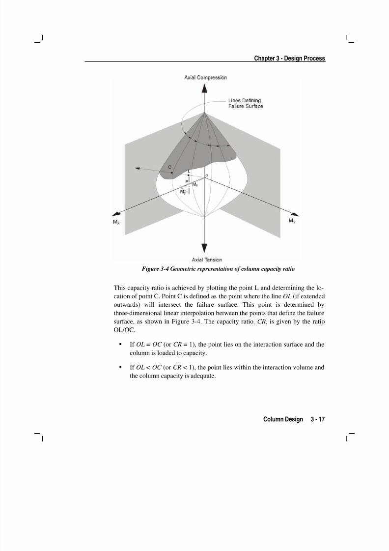
Figure 3-4 Geometric representation of column capacity ratio
This capacity ratio is achieved by plotting the point L and determining the lo-
cation of point C. Point C is defined as the point where the line OL (if extended
outwards) will intersect the failure surface. This point is determined by
three-dimensional linear interpolation between the points that define the failure
surface, as shown in Figure 3-4. The capacity ratio, CR, is given by the ratio
OL/OC.
If OL = OC (or CR = 1), the point lies on the interaction surface and the
column is loaded to capacity.
If OL < OC (or CR < 1), the point lies within the interaction volume andthe column capacity is adequate.

5/11/2018 53078408-CFD-Eurocode-2-2004 - slidepdf.com
http://slidepdf.com/reader/full/53078408-cfd-eurocode-2-2004 34/83
Design Manual Concrete Frame Eurocode 2-2004
3 - 18 Column Design
If OL > OC (or CR > 1), the point lies outside the interaction volume and
the column is overloaded.
The maximum of all the values of CR calculated from each design load com-
bination is reported for each check station of the column along with the con-
trolling N Ed
, M Ed2
, and M Ed3
set and associated design load combination name.
3.4.3 Design Longitudinal Reinforcement
If the reinforcing area is not defined, the program computes the required rein-
forcement that will give a column capacity ratio equal to the Utilization Factor
Limit, which is set to 0.95 by default.
3.4.4 Design Column Shear Reinforcement
The shear reinforcement is designed for each design combination in the major
and minor directions of the column. The following steps are involved in de-
signing the shear reinforcing for a particular column, for a particular design
load combination resulting from shear forces in a particular direction:
Determine the design forces acting on the section, N Ed
and V Ed
. Note that
N Ed
is needed for the calculation of V Rd,c
.
Determine the design shear resistance of the member without shear rein-forcement, V
Rd,c.
Determine the maximum design shear force that can be carried without
crushing of the notional concrete compressive struts, V Rd,max
.
Determine the required shear reinforcement as area per unit length, Asw /s.
The following four sections describe in detail the algorithms associated with
this process.
3.4.4.1 Determine Design Shear Force In the design of the column shear reinforcement of concrete frames, the forces
for a particular design load combination, namely, the column axial force, N Ed
,
and the column shear force, V Ed
, in a particular direction are obtained by fac-

5/11/2018 53078408-CFD-Eurocode-2-2004 - slidepdf.com
http://slidepdf.com/reader/full/53078408-cfd-eurocode-2-2004 35/83
Chapter 3 - Design Process
Column Design 3 - 19
toring the analysis cases with the corresponding design load combination fac-
tors.
3.4.4.2 Determine Design Shear Resistance
Given the design force set N Ed
and V Ed
, the shear force that can be carried with-
out requiring design shear reinforcement, V Rd,c
, is calculated as:
V Rd,c
= [C Rd,c
k (100 ρ l f
ck )
1/3+ k
1 σ
cp] b
wd (EC2 Eq. 6.2.a)
with a minimum of:
V Rd,c
= (vmin
+ k 1 σ
cp) b
wd (EC2 Eq. 6.2.b)
where f ck
is in MPa, and k , ρ l, and σ
cpare calculated as:
d k
2001+= ≤ 2.0 (d is in mm) (EC2 6.2.2(1))
ρ l=
d b
A
w
s ≤ 0.02 (EC2 6.2.2(1))
σ cp
= N Ed
/Ac< 0.2f
cd (in MPa)
(EC2 6.2.2(1))
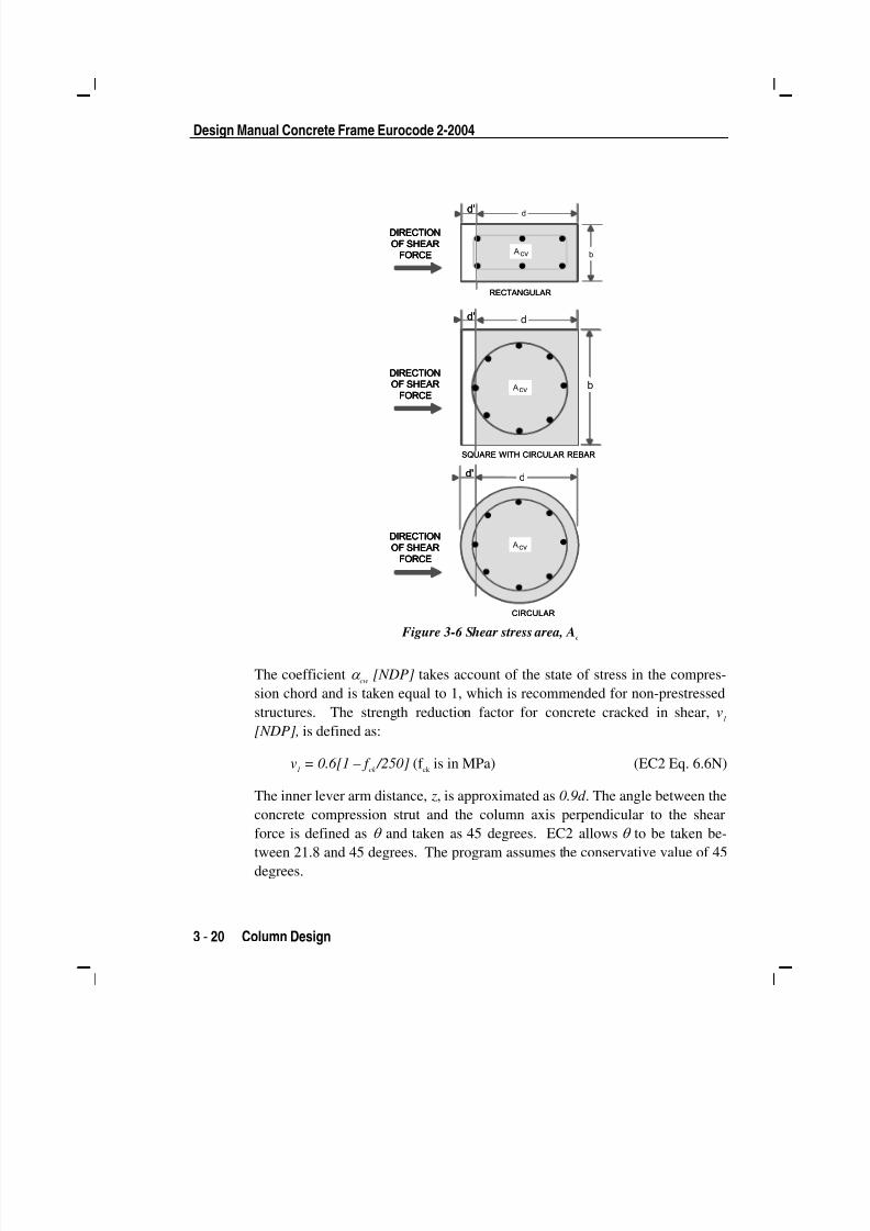
The effective shear area, Ac, is shown shaded in Figure 3-6. For circular col-umns, A
cis taken to be equal to the gross area of the section. The factor k
1=
0.15 [NDP] and the values of C Rd,c
[NDP] and vmin
[NDP] are determined as:
C Rd,c
= 0.18/ γ c
(EC2 6.2.2(1))
vmin
= 0.035 k 3/2
f ck
1/2(EC2 Eq. 6.3N)
3.4.4.3 Determine Maximum Design Shear Force
In order to prevent crushing of the concrete compression struts, the design
shear force V Ed
is limited by the maximum sustainable design shear force,
V Rd,max
. If the design shear force exceeds this limit, a failure condition occurs.
The maximum sustainable shear force is defined as:
V Rd,max
= α cw
bw z v
1 f
cd /(cot θ + tanθ ) (EC2 Eq. 6.9)
5/11/2018 53078408-CFD-Eurocode-2-2004 - slidepdf.com
http://slidepdf.com/reader/full/53078408-cfd-eurocode-2-2004 36/83
Design Manual Concrete Frame Eurocode 2-2004
3 - 20 Column Design
RECTANGULAR
dd'
b
dd'
b
cvA
SQUARE WITH CIRCULAR REBAR
cvA
cvA
CIRCULAR
dd'
DIRECTION
OF SHEAR
FORCE
DIRECTION
OF SHEAR
FORCE
DIRECTION
OF SHEAR
FORCE
RECTANGULAR
dd'
b
dd'
b
cvA
SQUARE WITH CIRCULAR REBAR
cvA
cvA
cvA
CIRCULAR
dd'
DIRECTION
OF SHEAR
FORCE
DIRECTION
OF SHEAR
FORCE
DIRECTION
OF SHEAR
FORCE
DIRECTION
OF SHEAR
FORCE
DIRECTION
OF SHEAR
FORCE
DIRECTION
OF SHEAR
FORCE
Figure 3-6 Shear stress area, A
c
The coefficient α cw
[NDP] takes account of the state of stress in the compres-
sion chord and is taken equal to 1, which is recommended for non-prestressed
structures. The strength reduction factor for concrete cracked in shear, v1
[NDP], is defined as:
v1
= 0.6[1 – f ck /250] (f
ck is in MPa) (EC2 Eq. 6.6N)
The inner lever arm distance, z, is approximated as 0.9d . The angle between the
concrete compression strut and the column axis perpendicular to the shearforce is defined as θ and taken as 45 degrees. EC2 allows θ to be taken be-
tween 21.8 and 45 degrees. The program assumes the conservative value of 45
degrees.

5/11/2018 53078408-CFD-Eurocode-2-2004 - slidepdf.com
http://slidepdf.com/reader/full/53078408-cfd-eurocode-2-2004 37/83
Chapter 3 - Design Process
Beam Design 3 - 21
3.4.4.4 Determine Required Shear Reinforcement
If V Ed
is greater than V Rd,c
and less than V Rd,max
, the required shear reinforcement
in the form of stirrups or ties per unit spacing, Asw /s, is calculated as:
θ cot ywd
Ed sw
zf
V
s
A= (EC2 Eq. 6.8)
In the preceding expressions, for a rectangular section, bw
is the width of the
column, d is the effective depth of the column, and Ac
is the effective shear
area, which is equal to bwd . For a circular section, b
wis replaced with D, which
is the external diameter of the column, d is replaced with 0.8D, and Ac
is re-
placed with the gross area π D2 /4.
The maximum of all the calculated Asw /s values, obtained from each design load
combination, is reported for the major and minor directions of the column,
along with the controlling combination name.
The column shear reinforcement requirements reported by the program are
based purely on shear strength consideration. Any minimum stirrup require-
ments to satisfy spacing considerations or transverse reinforcement volumetric
considerations must be investigated independently by the user.
3.5 Beam Design In the design of concrete beams, the program calculates and reports the re-
quired areas of steel for flexure and shear based on the beam moments, shear
forces, torsions, design load combination factors, and other criteria described in
the text that follows. The reinforcement requirements are calculated at a
user-defined number of output stations along the beam span.
All beams are designed for major direction flexure, shear, and torsion
only. Effects resulting from any axial forces and minor direction bending that
may exist in the beams must be investigated independently by the user.
The beam design procedure involves the following steps:
Design flexural reinforcement
Design shear reinforcement

5/11/2018 53078408-CFD-Eurocode-2-2004 - slidepdf.com
http://slidepdf.com/reader/full/53078408-cfd-eurocode-2-2004 38/83
Design Manual Concrete Frame Eurocode 2-2004
3 - 22 Beam Design
Design torsion reinforcement
3.5.1 Design Beam Flexural Reinforcement
The beam top and bottom flexural reinforcement is designed at output stations
along the beam span. The following steps are involved in designing the flexural
reinforcement for the major moment for a particular beam, at a particular sec-
tion:
Determine the maximum factored moments
Determine the required reinforcing steel
3.5.1.1 Determine Factored Moments
In the design of flexural reinforcement of concrete beams, the factored mo-
ments for each design load combination at a particular beam section are ob-
tained by factoring the corresponding moments for different analysis cases
with the corresponding design load combination factors.
The beam section is then designed for the factored moments obtained from
each of the design load combinations. Positive moments produce bottom steel.
In such cases, the beam may be designed as a rectangular or a T-beam. Nega-
tive moments produce top steel. In such cases, the beam is always designed asa rectangular section.
3.5.1.2 Determine Required Flexural Reinforcement
In the flexural reinforcement design process, the program calculates both the
tension and compression reinforcement. Compression reinforcement is added
when the applied design moment exceeds the maximum moment capacity of a
singly reinforced section. The user can avoid the need for compression rein-
forcement by increasing the effective depth, the width, or the grade of concrete.
The design procedure is based on a simplified rectangular stress block, asshown in Figure 3-7 (EC2 3.1.7(3)). When the applied moment exceeds the
moment capacity, the area of compression reinforcement is calculated on the

5/11/2018 53078408-CFD-Eurocode-2-2004 - slidepdf.com
http://slidepdf.com/reader/full/53078408-cfd-eurocode-2-2004 39/83
Chapter 3 - Design Process
Beam Design 3 - 23
assumption that the additional moment will be carried by compression and ad-
ditional tension reinforcement.
The design procedure used by the program for both rectangular and flanged
sections (T-beams) is summarized in the following subsections. It is assumed
that the design ultimate axial force is negligible, hence all beams are designed
ignoring axial force.
x
b
d h
A s
(i)BEAMSECTION
(ii) STRAINDIAGRAM
(iii) STRESSDIAGRAM
es
A's d'
Cs
TsTc
fs'
a= xl
ecu3 hfcd
Figure 3-7 Rectangular beam design
In designing for a factored negative or positive moment, M Ed
(i.e., designing
top or bottom steel), the effective strength and depth of the compression block
are given by η f cd
and λ x (see Figure 3-7) respectively, where:
λ = 0.8 for f ck ≤ 50 MPa, (EC2 Eq. 3.19)
λ = 0.8 – [(f ck
– 50)/400] for 50 < f ck ≤ 90 MPa (EC2 Eq. 3.20)
η = 1.0 for f ck ≤ 50 MPa (EC2 Eq. 3.21)
η = 1.0 – [(f ck
– 50)/200] for 50 < f ck ≤ 90 MPa (EC2 Eq. 3.22)

5/11/2018 53078408-CFD-Eurocode-2-2004 - slidepdf.com
http://slidepdf.com/reader/full/53078408-cfd-eurocode-2-2004 40/83
Design Manual Concrete Frame Eurocode 2-2004
3 - 24 Beam Design
where x is the depth of the neutral axis, λ is a factor defining the effective
height of the compression zone, and η is a factor defining the effectivestrength.
The limiting value of the ratio of the neutral axis depth at the ultimate limit
state to the effective depth, (x/d)lim
, is expressed as a function of the ratio of the
redistributed moment to the moment before redistribution, δ , as follows:
(x/d)lim
= (d – k 1)/k
2for f
ck ≤ 50 MPa (EC2 Eq. 5.10a)
(x/d)lim
= (d – k 3)/k
4for f
ck > 50 MPa (EC2 Eq. 5.10b)
No redistribution is assumed, such that δ is assumed taken to be 1. The four
factors, k 1, k 2, k 3, and k 4 [NDPs], are defined as:
k 1
= 0.44 (EC2 5.5(4))
k 2
= 1.25(0.6 + 0.0014/ ε cu2
) (EC2 5.5(4))
k 3
= 0.54 (EC2 5.5(4))
k 4
= 1.25(0.6 + 0.0014/ecu2
) (EC2 5.5(4))
where the ultimate strain, ε cu2
[NDP], is determined from EC2 Table 3.1 as:
ε cu2
= 0.0035 for f ck
< 50 MPa (EC2 Table 3.1)
ε cu2
= 2.6 + 35[(90 – f ck )/100]
4for f
ck ≥ 50 MPa (EC2 Table 3.1)
3.5.1.2.1 Rectangular Beam Flexural Reinforcement
For rectangular beams, the normalized moment, m, and the normalized section
capacity as a singly reinforced beam, mlim
, are determined as:
η =
cd
M m
bd f 2
⎥⎦⎤⎢
⎣⎡ ⎟ ⎠ ⎞⎜⎝ ⎛ −⎟ ⎠ ⎞⎜⎝ ⎛ =
limlim
lim2
1d x
d xm λ λ

5/11/2018 53078408-CFD-Eurocode-2-2004 - slidepdf.com
http://slidepdf.com/reader/full/53078408-cfd-eurocode-2-2004 41/83
Chapter 3 - Design Process
Beam Design 3 - 25
The reinforcing steel area is determined based on whether m is greater than,
less than, or equal to mlim.
If m ≤ mlim
, a singly reinforced beam will be adequate. Calculate the
normalized steel ratio, ω , and the required area of tension reinforce-
ment, As, as:
ω = 1− m21−
As= ω
η ⎡ ⎤⎢ ⎥⎢ ⎥⎣ ⎦
cd
yd
f bd
f
This area of reinforcing steel is to be placed at the bottom if M Ed ispositive, or at the top if M
Ed is negative.
If m > mlim
, compression reinforcement is required. Calculate the
normalized steel ratios, ω', ωlim
, and ω, as:
ω lim
= λ
lim
⎟ ⎠
⎞⎜⎝
⎛ d
x= 1 − lim21 m−
ω' =−
′−m m
d d
lim
1
ω = ωlim
+ ω'
where d' is the depth to the compression steel, measured from the
concrete compression face.
Calculate the required area of compression and tension reinforce-
ment, As' and A
s, as:
As' = ω'
η ⎡ ⎤⎢ ⎥
′⎢ ⎥⎣ ⎦
cd
s
f bd
f
As= ω
η ⎡ ⎤⎢ ⎥⎢ ⎥⎣ ⎦
cd
yd
f bd
f

5/11/2018 53078408-CFD-Eurocode-2-2004 - slidepdf.com
http://slidepdf.com/reader/full/53078408-cfd-eurocode-2-2004 42/83
Design Manual Concrete Frame Eurocode 2-2004
3 - 26 Beam Design
where f 's, the stress in the compression steel, is calculated as:
′s f = E
sε
c
′⎡ ⎤−⎢ ⎥
⎣ ⎦lim
d
x1 ≤ f
yd
Asis to be placed at the bottom and A
s' is to be placed at the top if M
Ed
is positive, and As' is to be placed at the bottom and A
sis to be placed
at the top if M Ed
is negative.
3.5.1.2.2 T-Beam Flexural Reinforcement
In designing a T-beam, a simplified stress block, as shown in Figure 3-8, is
assumed if the flange is in compression, i.e., if the moment is positive. If the
moment is negative, the flange is in tension, and therefore ignored. In this case,
a simplified stress block, similar to that shown in Figure 3-8, is assumed on the
compression side.
Flanged Beam Under Negative Moment
In designing for a factored negative moment, M Ed
(i.e., designing top steel), the
calculation of the reinforcing steel area is exactly the same as described for a
rectangular beam, i.e., no specific T-beam data is used.
Flanged Beam Under Positive Moment
In designing for a factored positive moment, M Ed
, the program analyzes the
section by considering the depth of the stress block. If the depth of the stress
block is less than or equal to the flange thickness, the section is designed as a
rectangular beam with a width b f . If the stress block extends into the web, addi-
tional calculation is required.
For T-beams, the normalized moment, m, and the normalized section capacity
as a singly reinforced beam, mlim
, are calculated as:
η = f cd
M m b d f 2
5/11/2018 53078408-CFD-Eurocode-2-2004 - slidepdf.com
http://slidepdf.com/reader/full/53078408-cfd-eurocode-2-2004 43/83
Chapter 3 - Design Process
Beam Design 3 - 27
⎥⎦
⎤
⎢⎣
⎡⎟ ⎠
⎞⎜⎝
⎛ −⎟ ⎠
⎞⎜⎝
⎛ =limlim
lim 21
d
x
d
xm
λ λ
Calculate the normalized steel ratios ωlim
and ω, as:
ω lim
= λ lim
⎟ ⎠
⎞⎜⎝
⎛ d
x
ω = 1 − m21 −
Calculate the maximum depth of the concrete compression block, amax
, and the
effective depth of the compression block, a, as:
amax
= ωlim
d
a = ωd
The reinforcing steel area is determined based on whether m is greater than,
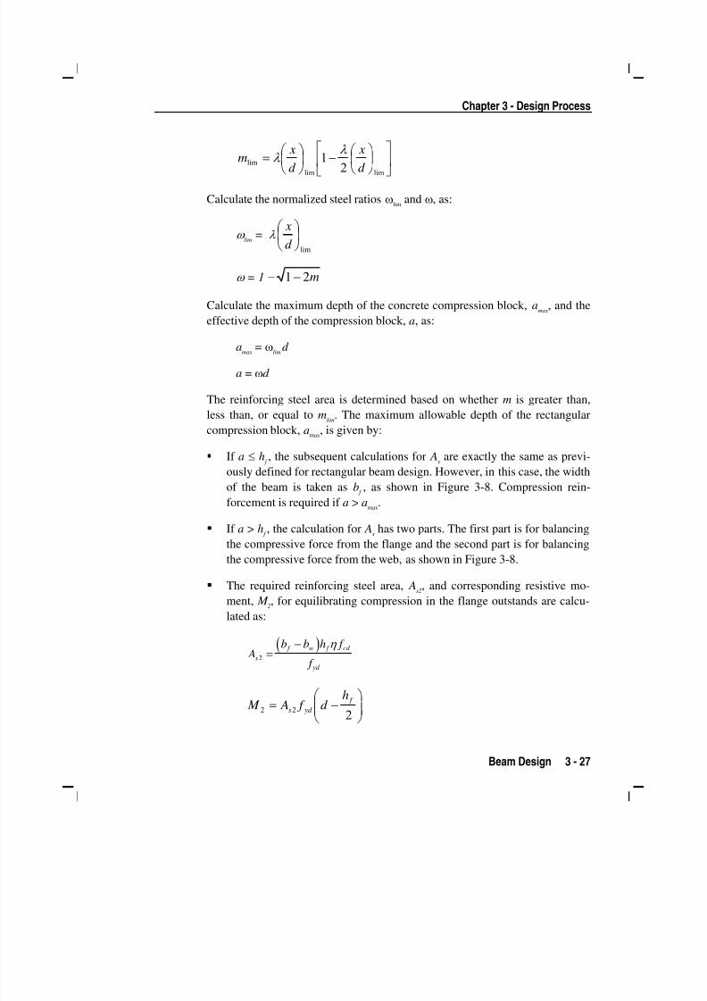
less than, or equal to mlim
. The maximum allowable depth of the rectangular
compression block, amax
, is given by:
If a ≤ h f , the subsequent calculations for A
sare exactly the same as previ-
ously defined for rectangular beam design. However, in this case, the width
of the beam is taken as b f , as shown in Figure 3-8. Compression rein-
forcement is required if a > amax.
If a > h f , the calculation for A
shas two parts. The first part is for balancing
the compressive force from the flange and the second part is for balancing
the compressive force from the web, as shown in Figure 3-8.
The required reinforcing steel area, As2, and corresponding resistive mo-
ment, M 2, for equilibrating compression in the flange outstands are calcu-
lated as:
( ) η −=
f w f cd
s
yd
b b h f A
f
2
⎟⎟ ⎠
⎞⎜⎜⎝
⎛ −=
222
f
yd s
hd f A M
5/11/2018 53078408-CFD-Eurocode-2-2004 - slidepdf.com
http://slidepdf.com/reader/full/53078408-cfd-eurocode-2-2004 44/83
Design Manual Concrete Frame Eurocode 2-2004
3 - 28 Beam Design
x
d
A s
(i)BEAMSECTION
(ii)STRAINDIAGRAM (iii)STRESSDIAGRAM
es
hf
Cf
Tf
C w
T w
b w
bf
As'
C s
Ts
d' fs'
ecu3 h fcd
a = xl
h fcd
Figure 3-8 T-beam design
Now calculate the required reinforcing steel area As1
for the rectangularsection of width b
wto resist the remaining moment M
1= M
Ed – M
2. The
normalized moment, m1is calculated as:
η =
w cd
M m
b d f
11 2
The reinforcing steel area is determined based on whether m1 is greaterthan, less than, or equal to m
lim.
If m1 ≤ m
lim, a singly reinforced beam will be adequate. Calculate the
normalized steel ratio, ω 1 , and the required area of tension rein-
forcement, As1, as:
ω 1
= 1− m21 −
As1
= ω1 η ⎡ ⎤
⎢ ⎥⎢ ⎥⎣ ⎦
cd
yd
f bd
f
If m1
> mlim
, compression reinforcement is required. Calculate the
normalized steel ratios, ω', ωlim
, and ω, as:
5/11/2018 53078408-CFD-Eurocode-2-2004 - slidepdf.com
http://slidepdf.com/reader/full/53078408-cfd-eurocode-2-2004 45/83
Chapter 3 - Design Process
Beam Design 3 - 29
ωlim
= λlim
⎟ ⎠
⎞⎜⎝
⎛
d
x
ω' =−
′−m m
d d
lim
1
ω1
= ωlim
+ ω'
where d' is the depth to the compression steel, measured from the
concrete compression face.
Calculate the required area of compression and tension reinforce-
ment, As
' and As
, as:
As' = ω'
η ⎡ ⎤⎢ ⎥
′⎢ ⎥⎣ ⎦
cd
s
f bd
f
As1
= ω1 η ⎡ ⎤
⎢ ⎥⎢ ⎥⎣ ⎦
cd
yd
f bd
f
where f s' , the stress in the compression steel, is calculated as:
′s f = E sε
c
′⎡ ⎤
−⎢ ⎥⎣ ⎦lim
d
x1 ≤ f yd
The total tensile reinforcement is As
= As1
+ As2, and the total compression
reinforcement is As' . A
sis to be placed at the bottom and A
s' is to be placed
at the top of the section.
3.5.1.3 Minimum and Maximum Tensile Reinforcement
The minimum flexural tensile steel reinforcement, As,min
[NDP], required in a
beam section is given as the maximum of the following two values:
As,min = 0.26 (f ctm /f yk )bt d (EC2 Eq. 9.1N)
As,min
= 0.0013bt d
5/11/2018 53078408-CFD-Eurocode-2-2004 - slidepdf.com
http://slidepdf.com/reader/full/53078408-cfd-eurocode-2-2004 46/83
Design Manual Concrete Frame Eurocode 2-2004
3 - 30 Beam Design
where bt
is the mean width of the tension zone, equal to the web width for
T-beams, and f ctm is the mean value of axial tensile strength of the concrete,calculated as:
f ctm
= 0.30f ck
(2/3)for f
ck ≤ 50 MPa (EC2 Table 3.1)
f ctm
= 2.12 ln(1 + f cm /10) for f
ck > 50 MPa (EC2 Table 3.1)
f cm
= f ck
+ 8 MPa
The maximum flexural steel reinforcement, As,max
[NDP], permitted as either
tension or compression reinforcement is defined as:
As,max
= 0.04Ac
(EC2 9.2.1.1(3))
where Acis the gross cross-sectional area.
3.5.2 Design Beam Shear Reinforcement
The required beam shear reinforcement is calculated for each design load com-
bination at each output station along the beam length. The following assump-
tions are made for the design of beam shear reinforcement:
The beam section is assumed to be prismatic. The shear capacity is based
on the beam width at the output station and therefore a variation in the
width of the beam is neglected in the calculation of the concrete shear ca-
pacity at each particular output station.
All shear reinforcement is assumed to be perpendicular to the longitudinal
reinforcement. Inclined shear steel is not handled.
The following steps are involved in designing the shear reinforcement for a
particular output station subjected to beam major shear:
Determine the design value of the applied shear force, V Ed
.
Determine the design shear resistance of the member without shear rein-
forcement, V Rd,c
.
Determine the maximum design shear force that can be carried without
crushing of the notional concrete compressive struts, V Rd,max
.
5/11/2018 53078408-CFD-Eurocode-2-2004 - slidepdf.com
http://slidepdf.com/reader/full/53078408-cfd-eurocode-2-2004 47/83
Chapter 3 - Design Process
Beam Design 3 - 31
Determine the required shear reinforcement as area per unit length, Asw /s.
The following four sections describe in detail the algorithms associated with
this process.
3.5.2.1 Determine Design Shear Force
In the design of the beam shear reinforcement, the shear forces and moments
for a particular design load combination at a particular beam section are ob-
tained by factoring the associated shear forces and moments with the corre-
sponding design load combination factors.
3.5.2.2 Determine Design Shear Resistance
The shear force that can be carried without requiring design shear reinforce-
ment, V Rd,c
, is calculated as:
V Rd,c
= [C Rd,c
k (100 ρ l f
ck )
1/3+ k
1 σ
cp] b
wd (EC2 Eq. 6.2.a)
with a minimum of:
V Rd,c
= (vmin
+ k 1 σ
cp) b
wd (EC2 Eq. 6.2.b)
where f ck
is in MPa, and k , ρ l, and σ
cpare calculated as:
d k
2001+= ≤ 2.0 (d is in mm) (EC2 6.2.2(1))
ρ l=
d b
A
w
s ≤ 0.02 (EC2 6.2.2(1))
σ cp
= N Ed
/Ac< 0.2f
cd (in MPa)
(EC2 6.2.2(1))
The effective shear area, Ac, is taken as b
wd . The factor k
1= 0.15 [NDP] and the
values of C Rd,c
[NDP] and vmin
[NDP] are determined as:
C Rd,c
= 0.18/ γ c
(EC2 6.2.2(1))
vmin
= 0.035 k 3/2
f ck
1/2(EC2 Eq. 6.3N)

5/11/2018 53078408-CFD-Eurocode-2-2004 - slidepdf.com
http://slidepdf.com/reader/full/53078408-cfd-eurocode-2-2004 48/83
Design Manual Concrete Frame Eurocode 2-2004
3 - 32 Beam Design
3.5.2.3 Determine Maximum Design Shear Force
In order to prevent crushing of the concrete compression struts, the design
shear force V Ed
is limited by the maximum sustainable design shear force,
V Rd,max
. If the design shear force exceeds this limit, a failure condition occurs.
The maximum sustainable shear force is defined as:
V Rd,max
= α cw
bw z v
1 f
cd /(cot θ + tanθ ) (EC2 Eq. 6.9)
The coefficient α cw
[NDP] takes account of the state of stress in the compres-
sion chord and is taken equal to 1 which is recommended for non-prestressed
structures. The strength reduction factor for concrete cracked in shear, v1
[NDP] is defined as:
v1
= 0.6[1 – f ck /250] ( f
ck is in MPa) (EC2 Eq. 6.6N)
The inner lever arm distance, z, is approximated as 0.9d . The angle between the
concrete compression strut and the beam axis perpendicular to the shear force
is defined as θ and taken as 45°.
3.5.2.4 Determine Required Shear Reinforcement
If V Ed
is greater than V Rd,c
and less than V Rd,max
, the required shear reinforcement
in the form of stirrups or ties per unit spacing, Asw /s, is calculated as:
θ cot ywd
Ed sw
zf
V
s
A= (EC2 Eq. 6.8)
The value of θ is conservatively taken as 45°.
The maximum of all the calculated Asw /s values, obtained from each design
load combination, is reported for the beam, along with the controlling combi-
nation name. The calculated shear reinforcement must be greater than the
minimum reinforcement ratio of:
( ) yk ck w f f / 08.0min, = ρ (EC2 Eq. 9.5N)
The beam shear reinforcement requirements reported by the program are based
purely on shear strength considerations. Any minimum stirrup requirements to
5/11/2018 53078408-CFD-Eurocode-2-2004 - slidepdf.com
http://slidepdf.com/reader/full/53078408-cfd-eurocode-2-2004 49/83
Chapter 3 - Design Process
Beam Design 3 - 33
satisfy spacing and volumetric consideration must be investigated independ-
ently of the program by the user.
3.5.3 Design Beam Torsion Reinforcement
The torsion reinforcement is designed for each design load combination at a
user-defined number of output stations along the beam span. The following
steps are involved in designing the longitudinal and shear reinforcement for a
particular station due to beam torsion:
Determine the factored torsion, T Ed
.
Determine torsion section properties.
Determine the torsional cracking moment.
Determine the reinforcement steel required.
3.5.3.1 Determine Factored Torsion
In the design of torsion reinforcement of any beam, the factored torsions for
each design load combination at a particular design station are obtained by
factoring the corresponding torsion for different analysis cases with the corre-
sponding design load combination factors.
3.5.3.2 Determine Torsion Section Properties
For torsion design, special torsion section properties including Ak , t
ef , u, u
k , and
ziare calculated. These properties are described as follows (EC2 6.3).
Ak = Area enclosed by centerlines of the connecting walls, where the
centerline is located a distance of t ef /2 from the outer surface
t ef
= Effective wall thickness
u = Outer perimeter of the cross-section
uk
= Perimeter of the area Ak
zi= Side length of wall i, defined as the distance between the intersec-
tion points of the wall centerlines
5/11/2018 53078408-CFD-Eurocode-2-2004 - slidepdf.com
http://slidepdf.com/reader/full/53078408-cfd-eurocode-2-2004 50/83
Design Manual Concrete Frame Eurocode 2-2004
3 - 34 Beam Design
For torsion design of T-beam sections, it is assumed that placing torsion rein-
forcement in the flange area is inefficient. With this assumption, the flange isignored for torsion reinforcement calculation. However, the flange is consid-
ered during calculation of the torsion section properties. With this assumption,
the special properties for a Rectangular beam section are given as follows:
A = bh
Ak
= (b – t ef )(h – t
ef )
u = 2b + 2h
uk
= 2(b – t ef ) + 2(h – t
ef )
where, the section dimensions b, h, and t ef
are shown in Figure 3-9. Similarly,
the special section properties for a T-beam section are given as follows:
A = ( )+ −w f w sb h b b d
Ak
= (b f
– t ef )(h – t
ef )
u = 2b f
+ 2h
uk
= 2(b f
– t ef ) + 2(h – t
ef )
where the section dimensions b f , b
w, h, and d
sfor a T-beam are shown in
Figure 3-9.
3.5.3.3 Determine Torsional Cracking Moment
The torsion in the section can be ignored with only minimum shear reinforce-
ment (EC2 9.2.1.1) necessary if the following condition is satisfied:
T Ed
/T Rd,c
+ V Ed
/V Rd,c
≤ 1.0 (EC2 Eq. 6.31)
where T Rd,c
is the torsional cracking moment, determined as:
T Rd,c
= f ctd
t ef 2A
k
where t ef , and f
ctd , the design tensile strength, are defined as:
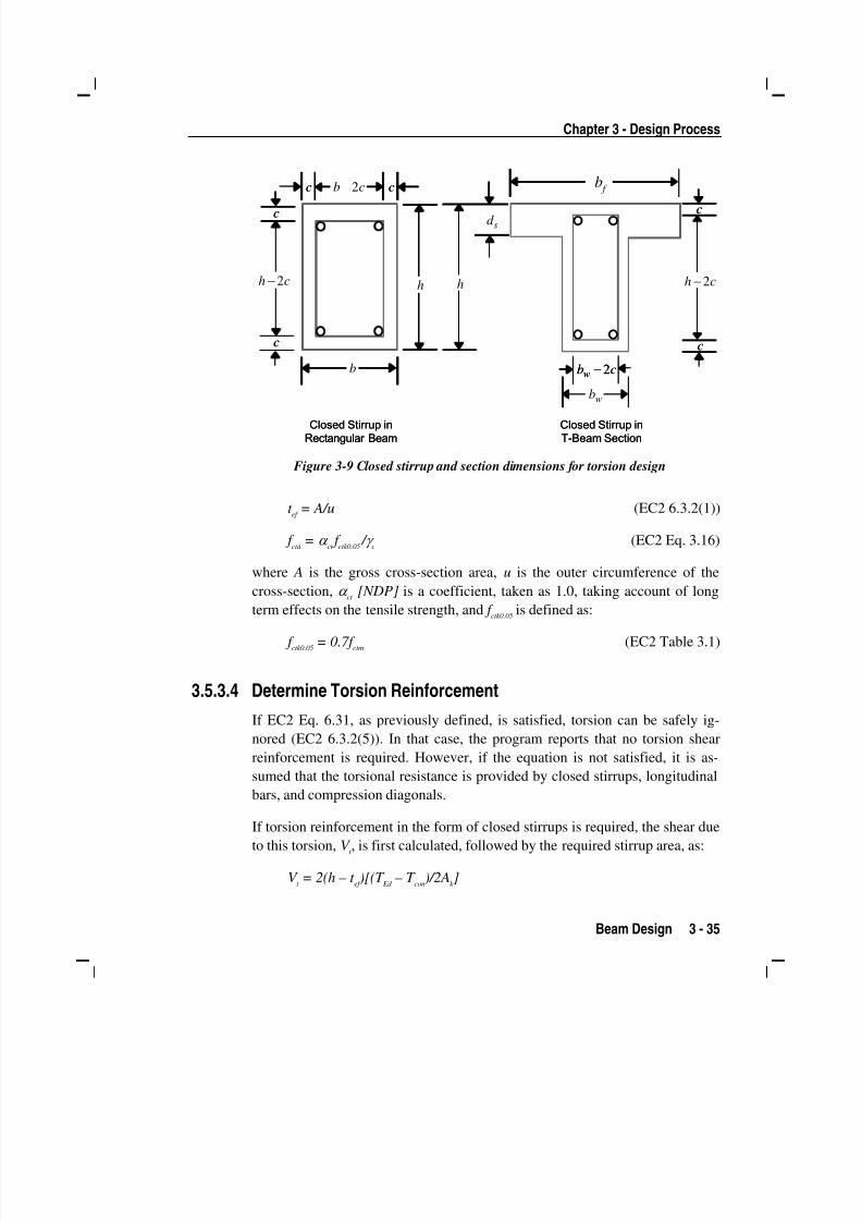
5/11/2018 53078408-CFD-Eurocode-2-2004 - slidepdf.com
http://slidepdf.com/reader/full/53078408-cfd-eurocode-2-2004 51/83
Chapter 3 - Design Process
Beam Design 3 - 35
cbw 2−
c
c
cc
c
c
cb 2−
h
sd
Closed Stirrup in
Rectangular Beam
Closed Stirrup in
T-Beam Section
ch 2− h
b
ch 2−
wb
b f
cbw 2−
c
c
cc
c
c
cb 2−
h
sd
Closed Stirrup in
Rectangular Beam
Closed Stirrup in
T-Beam Section
ch 2− h
b
ch 2−
wb
b f
Figure 3-9 Closed stirrup and section dimensions for torsion design
t ef
= A/u (EC2 6.3.2(1))
f ctd
= α ct f
ctk0.05 / γ
c (EC2 Eq. 3.16)
where A is the gross cross-section area, u is the outer circumference of the
cross-section, α ct [NDP] is a coefficient, taken as 1.0, taking account of long
term effects on the tensile strength, and f ctk0.05 is defined as:
f ctk0.05
= 0.7f ctm
(EC2 Table 3.1)
3.5.3.4 Determine Torsion Reinforcement
If EC2 Eq. 6.31, as previously defined, is satisfied, torsion can be safely ig-
nored (EC2 6.3.2(5)). In that case, the program reports that no torsion shear
reinforcement is required. However, if the equation is not satisfied, it is as-
sumed that the torsional resistance is provided by closed stirrups, longitudinal
bars, and compression diagonals.
If torsion reinforcement in the form of closed stirrups is required, the shear due
to this torsion, V t , is first calculated, followed by the required stirrup area, as:
V t = 2(h – t
ef )[(T
Ed – T
con)/2A
k ]
5/11/2018 53078408-CFD-Eurocode-2-2004 - slidepdf.com
http://slidepdf.com/reader/full/53078408-cfd-eurocode-2-2004 52/83
Design Manual Concrete Frame Eurocode 2-2004
3 - 36 Beam Design
θ cot ywd
t t
zf
V
s
A=
The required longitudinal reinforcement area for torsion is defined as:
yd
k
k
Ed sl
f
u
A
T A θ cot
2= (EC2 Eq. 6.28)
where θ is the angle of the compression struts, as previously defined for beam
shear. In the preceding expressions, θ is taken as 45°. The code allows any
value between 21.8 and 45° (EC2 6.2.3(2)), while the program assumes the
conservative value of 45°.
An upper limit of the combination of V Ed
and T Ed
that can be carried by the sec-
tion without exceeding the capacity of the concrete struts is also checked using
the following equation.
0.1max,max,
≤+ Rd
Ed
Rd
Ed
V
V
T
T (EC2 Eq. 6.29)
where, T Rd,max
, the design torsional resistance moment is defined as:
T Rd,max
= 2να cw f
cd A
k t
ef sinθ cosθ (EC2 Eq. 6.30)
The value ν is defined by EC2 Eq. 6.6N. If the combination of V Ed and T Ed ex-ceeds this limit, a failure message is declared. In that case, the concrete section
should be increased in size.
The maximum of all the calculated Asl
and At /s values obtained from each de-
sign load combination is reported along with the controlling combination
names.
The beam torsion reinforcement requirements reported by the program are
based purely on strength considerations. Any minimum stirrup requirements
and longitudinal rebar requirements to satisfy spacing considerations must be
investigated independently of the program by the user.
5/11/2018 53078408-CFD-Eurocode-2-2004 - slidepdf.com
http://slidepdf.com/reader/full/53078408-cfd-eurocode-2-2004 53/83
4 - 1
Chapter 4 Design Output
4.1 Overview
The program creates design output in different formats – graphical display,
tabular output, and member specific detailed design information.
The graphical display of design output includes input and output design infor-mation. Input design information includes design section labels, β -factors, live
load reduction factors, and other design parameters. The output design infor-
mation includes longitudinal reinforcing, shear reinforcing, torsional reinforc-
ing, and column capacity ratios. All graphical output can be printed.
The tabular output can be saved in a file or printed. The tabular output includes
most of the information that can be displayed. This is generated for added
convenience to the designer.
The member specific detailed design information shows the details of the cal-
culation from the designer’s point of view. It shows the design forces, design
section dimensions, reinforcement, and some intermediate results for all of the
load combinations at all of the design sections of a specific frame member. For
a column member, it can also show the position of the current state of design
forces on the column interaction diagram.

5/11/2018 53078408-CFD-Eurocode-2-2004 - slidepdf.com
http://slidepdf.com/reader/full/53078408-cfd-eurocode-2-2004 54/83
Design Manual Concrete Frame Eurocode 2-2004
4 - 2 Graphical Display of Design Information
In the following sections, some of the typical graphical display, tabular output,
spreadsheet output, and member specific detailed design information are de-scribed. The Eurocode 2-2004 design code is described in this manual.
4.2 Graphical Display of Design Information
The graphical display of design output includes input and output design infor-
mation. Input design information includes design section labels, β -factors, live
load reduction factors, and other design parameters. The output design infor-
mation includes longitudinal reinforcing, shear reinforcing, torsion reinforcing,
column capacity ratio, and other design information.
The graphical output can be produced in color or in gray-scale screen display.The active screen display can be sent directly to the printer.
4.2.1 Input and Output
Input design information for the Eurocode 2-2004 code includes the following:
Design sections
Design framing type
Live load reduction factors (RLLF)
Unbraced length, L-factors, for major and minor direction of bending
Effective length factors, β -factors, for major and minor direction of bend-
ing
The output design information that can be displayed consists of the following:
Longitudinal reinforcing area
Longitudinal reinforcing area as percent of concrete gross area
Shear reinforcing areas per unit spacing
Column P-M-M interaction ratios
General reinforcing details

5/11/2018 53078408-CFD-Eurocode-2-2004 - slidepdf.com
http://slidepdf.com/reader/full/53078408-cfd-eurocode-2-2004 55/83
Chapter 4 - Design Output
Graphical Display of Design Information 4 - 3
Use the Design menu > Concrete Frame Design > Display Design Info
command to plot input and output values directly on the model in the activewindow. Clicking this command will access the Display Design Results form.
Select the Design Output or Design Input option, and then use the drop-down
lists to choose the type of design data to be displayed, such as longitudinal re-
inforcement, rebar percentages, shear reinforcing and so on. Click theOK but-
ton on the form to close the form and display the selected data in the active
window.
The graphical displays can be viewed in 2D or 3D mode. Use the various tool-
bar buttons (e.g., Set Default 3D View, Set X-Y View) to adjust the view, or
use the View menu > Set 2D View or View menu > Set 3D View commands
to refine the display.
The graphical display in the active window can be printed by clicking the File
menu > Print Graphics command, the Print Graphics button on the toolbar,
or the Ctrl+G keyboard shortcut. The display can also be captured as a bitmap
file (.bmp) using one of the subcommands on the File menu > Capture Pic-
ture command, or as a metafile (.emf) using one of the subcommands on the
File menu > Capture Enhanced Metafile command. The captured picture file
can then be used in popular graphics programs, including Paint and Power-
Point. Alternatively, the standard Windows screen capture command (using the
Print Screen button on the keyboard) can be used to create a screen capture of
the entire window, or use the Alt+Print Screen command to capture only the
"top layer," such as a form displayed from within the program.
By default, graphics are displayed and printed in color, assuming a color
printer is available. Use the Options menu > Colors > Output command to
change default colors, as necessary, including changing the background color
from the default black to white. A white background can be useful when print-
ing design output to save ink/toner. In addition, theOptions menu > Colors >
Set Active Theme command can be used to view or print graphics in gray-
scale.

5/11/2018 53078408-CFD-Eurocode-2-2004 - slidepdf.com
http://slidepdf.com/reader/full/53078408-cfd-eurocode-2-2004 56/83
Design Manual Concrete Frame Eurocode 2-2004
4 - 4 Tabular Display of Design Output
4.3 Tabular Display of Design Output
The tabular design output can be sent directly to a printer or saved to a file. The
printed form of the tabular output is the same as that produced for the file out-
put except that the font size is adjusted for the printed output.
The tabular design output includes input and output design information that
depends on the design code chosen. For the Eurocode 2-2004 design code, the
tabular output includes the following. All tables have formal headings and are
self-explanatory, so further description of these tables is not given.
Input design information includes the following:
Concrete Column Property Data
- Material label
- Column dimensions
- Reinforcement pattern
- Concrete cover
- Bar area
Concrete Beam Property Data
- Material label
- Beam dimensions
- Top and bottom concrete cover
- Top and bottom reinforcement areas
Load Combination Multipliers
- Combination name
- Load types
- Load factors
Concrete Design Element Information
- Design section ID
- Factors for major and minor direction of bending
- Unbraced length ratios for major and minor direction of bending, L-factors
- Live load reduction factors (RLLF)

5/11/2018 53078408-CFD-Eurocode-2-2004 - slidepdf.com
http://slidepdf.com/reader/full/53078408-cfd-eurocode-2-2004 57/83
Chapter 4 - Design Output
Member Specific Information 4 - 5
Concrete Moment Magnification Factors
- Section ID
- Element type
- Framing type
- δ ns -factors
- δ s -factors
The output design information includes the following:
Column design Information
- Section ID
- Station location
- Total longitudinal reinforcement and the governing load combination- Major shear reinforcement and the governing load combination
- Minor shear reinforcement and the governing load combination
Beam Design Information
- Section ID
- Station location
- Top longitudinal reinforcement and the governing load combination
- Bottom reinforcement and the governing load combination
- Longitudinal torsional reinforcement and the governing load combi-
nation
- Major shear reinforcement and the governing load combination forshear and torsion design
Tabular output can be printed directly to a printer or saved in a file using the
File menu > Print Tables command. A form will display when this command
is used. Press the F1 key on the keyboard to access the Help topic specific to
that form, which will identify the types of output available (e.g., plain text with
or without page breaks, rich text format Word document, and so on).
4.4 Member Specific Information
Member specific design information shows the details of the calculation from
the designer's point of view. It includes the geometry and material data, other
input data, design forces, design section dimensions, reinforcement details, and
some of the intermediate results for the selected member. The design detail in-

5/11/2018 53078408-CFD-Eurocode-2-2004 - slidepdf.com
http://slidepdf.com/reader/full/53078408-cfd-eurocode-2-2004 58/83
Design Manual Concrete Frame Eurocode 2-2004
4 - 6 Member Specific Information
formation can be displayed for a specific load combination and for a specific
station of a column or beam member. For columns, member specific designinformation can also show the position of the current state of design forces us-
ing a column interaction diagram.
After an analysis has been performed and the Design menu > Concrete
Frame Design > Start Design/Check command has been used, access the de-
tailed design information by right clicking a frame member to display the Con-
crete Column Design Information form if a column member was right clicked
or the Concrete Beam Design Information form if a beam member was right
clicked. Table 4-1 identifies the types of data provided by the forms.
The longitudinal and shear reinforcing area are reported in their current units,
which are displayed in the drop-down list in the lower right corner of the pro-
gram window. Typically, the longitudinal reinforcing area is reported in in2,
mm2, cm
2and so on. Shear reinforcing areas typically are reported in in
2 /in,
mm2 /mm, cm
2 /cm and so on.
Table 4-1 Member Specific Data for Columns and Beams
Column Beam
Load combination ID
Station locations
Longitudinal reinforcement area
Major shear reinforcement areas
Minor shear reinforcement areas
Load combination ID
Station location
Top reinforcement areas
Bottom reinforcement areas Longitudinal reinforcement for torsion design
Shear reinforcement area for shear
Shear reinforcement area for torsion design
Buttons on the forms can be used to access additional forms that provide the following data
Overwrites
– Element section ID
– Element framing type
– Code-dependent factors
– Live load reduction factors
– Effective length factors, β , for majorand minor direction bending
Overwrites
– Element section ID
– Element framing type
– Code-dependent factors
– Live load reduction factors
– Effective length factors, β , for major andminor direction bending
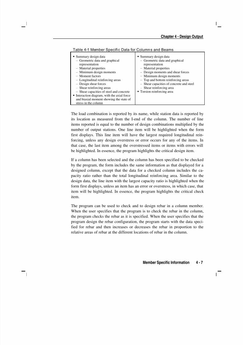
5/11/2018 53078408-CFD-Eurocode-2-2004 - slidepdf.com
http://slidepdf.com/reader/full/53078408-cfd-eurocode-2-2004 59/83
Chapter 4 - Design Output
Member Specific Information 4 - 7
Table 4-1 Member Specific Data for Columns and Beams
Summary design data– Geometric data and graphical
representation
– Material properties
– Minimum design moments
– Moment factors
– Longitudinal reinforcing areas
– Design shear forces
– Shear reinforcing areas
– Shear capacities of steel and concrete
Interaction diagram, with the axial forceand biaxial moment showing the state of stress in the column
Summary design data– Geometric data and graphical
representation
– Material properties
– Design moments and shear forces
– Minimum design moments
– Top and bottom reinforcing areas
– Shear capacities of concrete and steel
– Shear reinforcing area
Torsion reinforcing area
The load combination is reported by its name, while station data is reported byits location as measured from the I-end of the column. The number of line
items reported is equal to the number of design combinations multiplied by the
number of output stations. One line item will be highlighted when the form
first displays. This line item will have the largest required longitudinal rein-
forcing, unless any design overstress or error occurs for any of the items. In
that case, the last item among the overstressed items or items with errors will
be highlighted. In essence, the program highlights the critical design item.
If a column has been selected and the column has been specified to be checked
by the program, the form includes the same information as that displayed for a
designed column, except that the data for a checked column includes the ca-pacity ratio rather than the total longitudinal reinforcing area. Similar to the
design data, the line item with the largest capacity ratio is highlighted when the
form first displays, unless an item has an error or overstress, in which case, that
item will be highlighted. In essence, the program highlights the critical check
item.
The program can be used to check and to design rebar in a column member.
When the user specifies that the program is to check the rebar in the column,
the program checks the rebar as it is specified. When the user specifies that the
program design the rebar configuration, the program starts with the data speci-
fied for rebar and then increases or decreases the rebar in proportion to the
relative areas of rebar at the different locations of rebar in the column.

5/11/2018 53078408-CFD-Eurocode-2-2004 - slidepdf.com
http://slidepdf.com/reader/full/53078408-cfd-eurocode-2-2004 60/83
Design Manual Concrete Frame Eurocode 2-2004
4 - 8 Member Specific Information
4.4.1 Interactive Concrete Frame Design
The interactive concrete frame design and review is a powerful mode that al-
lows the user to review the design results for any concrete frame design, to re-
vise the design assumptions interactively, and to review the revised results
immediately.
Before entering the interactive concrete frame design mode, the design results
must be available for at least one member. That means the design must have
been run for all the members or for only selected members. If the initial design
has not been performed yet, run a design by clicking theDesign menu > Con-
crete Frame Design > Start Design/Check of Structure command.
There are three ways to initiate the interactive concrete frame design mode:
Click the Design menu > Concrete Frame Design > Start Design/Check
of Structures command to run a design.
Click the Design menu > Concrete frame Design > Display Design Info
command to access the Display Design Results form and select a type of
result.
Click the Design menu > Concrete Frame Design > Interactive Con-
crete Frame Design command.
After using any of the three commands, right click on a frame member to enter
the interactive Concrete Frame Design Mode and access the Concrete Column
Design Information form if a column member was right clicked or the Con-
crete Beam Design Information form if a beam member was right clicked.
These forms have Overwrites buttons that accesses the Concrete Frame De-
sign Overwrites form. The form can be used to change the design sections,
element type, live load reduction factor for reducible live load, and many other
design factors. See Appendix D for a detailed description of the overwrite
items. When changes to the design parameters are made using the Overwrites
form, the Concrete Beam or Column Design Information forms update imme-
diately to reflect the changes. Other buttons on the Concrete Beam or Column
Design Information forms can then be used to display additional forms show-
ing the details of the updated design. See the Member Specific Information sec-
tion of this chapter for more information.

5/11/2018 53078408-CFD-Eurocode-2-2004 - slidepdf.com
http://slidepdf.com/reader/full/53078408-cfd-eurocode-2-2004 61/83
Chapter 4 - Design Output
Error Messages and Warnings 4 - 9
In this way, the user can change the overwrites any number of times to produce
a satisfactory design. After an acceptable design has been produced by chang-ing the section or other design parameters, click theOK button on the Concrete
Beam or Column Design Information forms to permanently change the design
sections and other overwrites for that member. However, if the Cancel button
is used, all changes made to the design parameters using the Concrete Frame
Design Overwrites form are temporary and do not affect the design.
4.5 Error Messages and Warnings
In many places of concrete frame design output, error messages and warnings
are displayed. The messages are numbered. A complete list of error messages
and warnings used in Concrete Frame Design for all the design codes is pro-
vided in Appendix E. However, all of the messages are not applicable to the
Eurocode 2-2004 design code.

5/11/2018 53078408-CFD-Eurocode-2-2004 - slidepdf.com
http://slidepdf.com/reader/full/53078408-cfd-eurocode-2-2004 62/83

5/11/2018 53078408-CFD-Eurocode-2-2004 - slidepdf.com
http://slidepdf.com/reader/full/53078408-cfd-eurocode-2-2004 63/83
APPENDICES

5/11/2018 53078408-CFD-Eurocode-2-2004 - slidepdf.com
http://slidepdf.com/reader/full/53078408-cfd-eurocode-2-2004 64/83
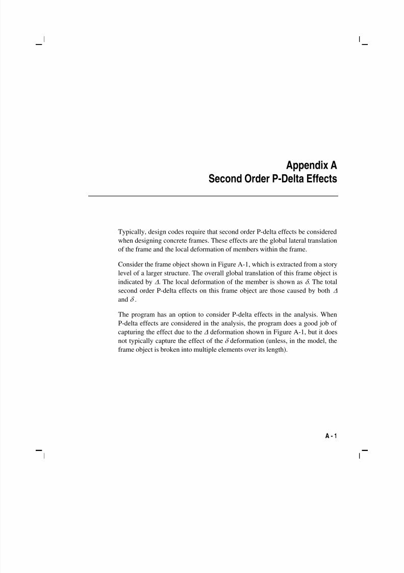
5/11/2018 53078408-CFD-Eurocode-2-2004 - slidepdf.com
http://slidepdf.com/reader/full/53078408-cfd-eurocode-2-2004 65/83
A - 1
Appendix A Second Order P-Delta Effects
Typically, design codes require that second order P-delta effects be considered
when designing concrete frames. These effects are the global lateral translation
of the frame and the local deformation of members within the frame.
Consider the frame object shown in Figure A-1, which is extracted from a story
level of a larger structure. The overall global translation of this frame object is
indicated by Δ. The local deformation of the member is shown as δ . The total
second order P-delta effects on this frame object are those caused by both Δ
and δ .
The program has an option to consider P-delta effects in the analysis. When
P-delta effects are considered in the analysis, the program does a good job of
capturing the effect due to the Δ deformation shown in Figure A-1, but it does
not typically capture the effect of the δ deformation (unless, in the model, the
frame object is broken into multiple elements over its length).
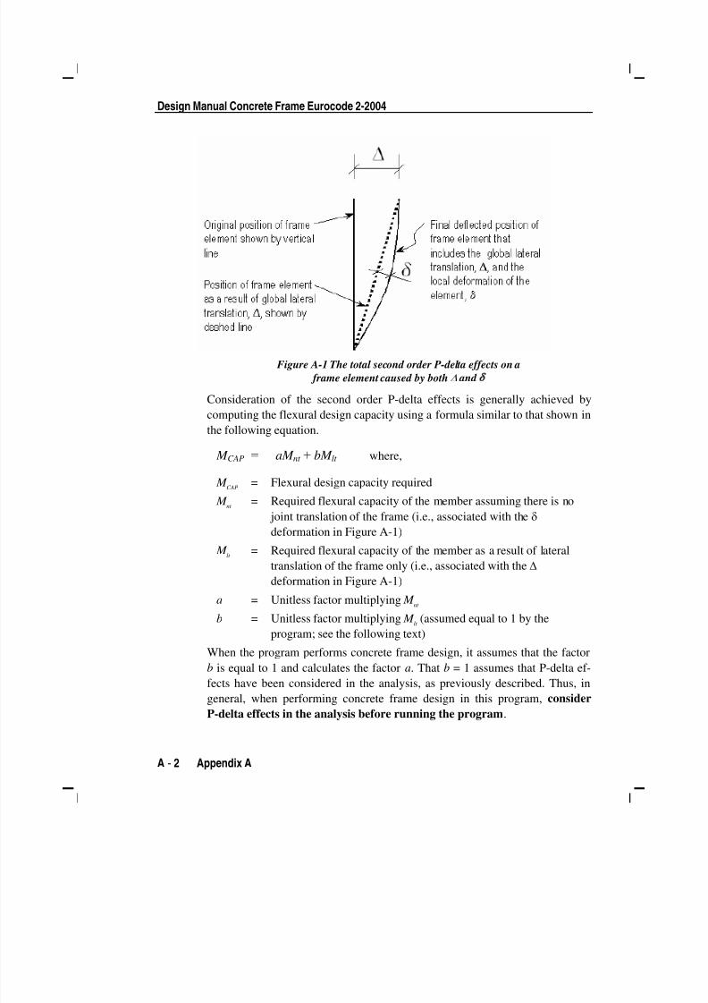
5/11/2018 53078408-CFD-Eurocode-2-2004 - slidepdf.com
http://slidepdf.com/reader/full/53078408-cfd-eurocode-2-2004 66/83
Design Manual Concrete Frame Eurocode 2-2004
A - 2 Appendix A
Figure A-1 The total second order P-delta effects on a
frame element caused by both Δ and δ
Consideration of the second order P-delta effects is generally achieved by
computing the flexural design capacity using a formula similar to that shown in
the following equation.
M CAP = aM nt + bM lt where,
M CAP
= Flexural design capacity required
M nt = Required flexural capacity of the member assuming there is no joint translation of the frame (i.e., associated with the δ
deformation in Figure A-1)
M lt = Required flexural capacity of the member as a result of lateral
translation of the frame only (i.e., associated with the Δ
deformation in Figure A-1)
a = Unitless factor multiplying M nt
b = Unitless factor multiplying M lt
(assumed equal to 1 by the
program; see the following text)
When the program performs concrete frame design, it assumes that the factor
b is equal to 1 and calculates the factor a. That b = 1 assumes that P-delta ef-fects have been considered in the analysis, as previously described. Thus, in
general, when performing concrete frame design in this program, consider
P-delta effects in the analysis before running the program.

5/11/2018 53078408-CFD-Eurocode-2-2004 - slidepdf.com
http://slidepdf.com/reader/full/53078408-cfd-eurocode-2-2004 67/83
B - 1
Appendix B Member Unsupported Lengths and
Computation of β-Factors
The column unsupported lengths are required to account for column slender-
ness effects. The program automatically determines the unsupported length ra-
tios, which are specified as a fraction of the frame object length. Those ratios
times the frame object length give the unbraced lengths for the members.
Those ratios also can be overwritten by the user on a member-by-member
basis, if desired, using the overwrite option.
There are two unsupported lengths to consider. They are l33
and l22, as shown in
Figure B-1. These are the lengths between support points of the member in the
corresponding directions. The length l33
corresponds to instability about the 3-3
axis (major axis), and l22
corresponds to instability about the 2-2 axis (minor
axis).

5/11/2018 53078408-CFD-Eurocode-2-2004 - slidepdf.com
http://slidepdf.com/reader/full/53078408-cfd-eurocode-2-2004 68/83
Design Manual Concrete Frame Eurocode 2-2004
B - 2 Member Unsupported Lengths and Computation of K-Factors
Figure B-1 Axis of bending and unsupported length
In determining the values for l22
and l33
of the members, the program recognizes
various aspects of the structure that have an effect on those lengths, such as
member connectivity, diaphragm constraints and support points. The program
automatically locates the member support points and evaluates the corre-
sponding unsupported length.
It is possible for the unsupported length of a frame object to be evaluated by
the program as greater than the corresponding member length. For example,
assume a column has a beam framing into it in one direction, but not the other,
at a floor level. In that case, the column is assumed to be supported in one di-
rection only at that story level, and its unsupported length in the other direction
will exceed the story height.
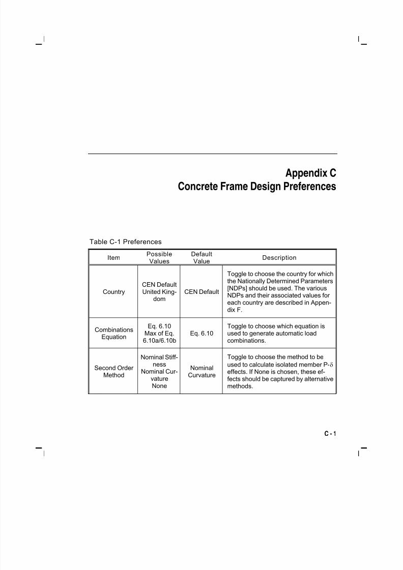
5/11/2018 53078408-CFD-Eurocode-2-2004 - slidepdf.com
http://slidepdf.com/reader/full/53078408-cfd-eurocode-2-2004 69/83
C - 1
Appendix C
Concrete Frame Design Preferences
Table C-1 Preferences
ItemPossibleValues
DefaultValue
Description
CountryCEN DefaultUnited King-
domCEN Default
Toggle to choose the country for whichthe Nationally Determined Parameters[NDPs] should be used. The variousNDPs and their associated values for each country are described in Appen-dix F.
CombinationsEquation
Eq. 6.10Max of Eq.6.10a/6.10b
Eq. 6.10Toggle to choose which equation isused to generate automatic loadcombinations.
Second Order Method
Nominal Stiff-ness
Nominal Cur-
vatureNone
NominalCurvature
Toggle to choose the method to be
used to calculate isolated member P-δ effects. If None is chosen, these ef-
fects should be captured by alternativemethods.
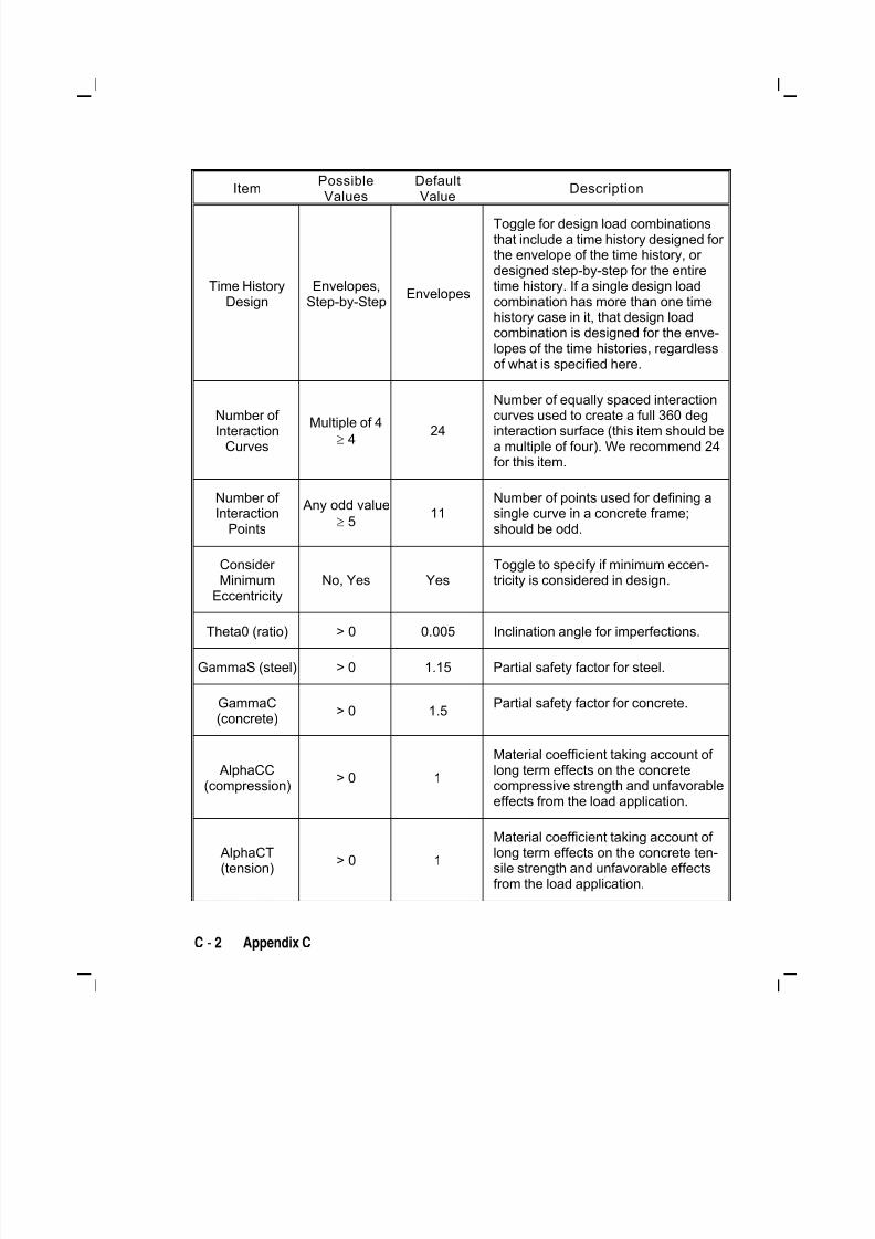
5/11/2018 53078408-CFD-Eurocode-2-2004 - slidepdf.com
http://slidepdf.com/reader/full/53078408-cfd-eurocode-2-2004 70/83
C - 2 Appendix C
ItemPossibleValues
DefaultValue
Description
Time HistoryDesign
Envelopes,Step-by-Step
Envelopes
Toggle for design load combinationsthat include a time history designed for the envelope of the time history, or designed step-by-step for the entiretime history. If a single design loadcombination has more than one timehistory case in it, that design loadcombination is designed for the enve-lopes of the time histories, regardlessof what is specified here.
Number of Interaction
Curves
Multiple of 4
≥ 424
Number of equally spaced interaction
curves used to create a full 360 deg interaction surface (this item should bea multiple of four). We recommend 24for this item.
Number of Interaction
Points
Any odd value
≥ 511
Number of points used for defining asingle curve in a concrete frame;should be odd.
Consider Minimum
EccentricityNo, Yes Yes
Toggle to specify if minimum eccen-tricity is considered in design.
Theta0 (ratio) > 0 0.005 Inclination angle for imperfections.
GammaS (steel) > 0 1.15 Partial safety factor for steel.
GammaC(concrete)
> 0 1.5Partial safety factor for concrete.
AlphaCC(compression)
> 0 1
Material coefficient taking account of long term effects on the concretecompressive strength and unfavorableeffects from the load application.
AlphaCT(tension)
> 0 1
Material coefficient taking account of long term effects on the concrete ten-sile strength and unfavorable effectsfrom the load application.

5/11/2018 53078408-CFD-Eurocode-2-2004 - slidepdf.com
http://slidepdf.com/reader/full/53078408-cfd-eurocode-2-2004 71/83
Appendix C – Concrete Frame Design Preferences
Preferences C - 3
ItemPossibleValues
DefaultValue
Description
AlphaLCC(Lightweight
compression)> 0 0.85
Light-weight material coefficient takingaccount of long term effects on theconcrete compressive strength andunfavorable effects from the load ap-plication.
AlphaLCT(Lightweight
tension)> 0 0.85
Light-weight material coefficient takingaccount of long term effects on theconcrete tensile strength and unfa-vorable effects from the load applica-tion.
Pattern LiveLoad Factor
≥ 0 0.75
The live load factor for automaticgeneration of load combinations in-volving pattern live loads and deadloads.
Utilization Factor Limit
> 0 0.95Stress ratios that are less than or equalto this value are considered accept-able.

5/11/2018 53078408-CFD-Eurocode-2-2004 - slidepdf.com
http://slidepdf.com/reader/full/53078408-cfd-eurocode-2-2004 72/83
C - 4 Appendix C
5/11/2018 53078408-CFD-Eurocode-2-2004 - slidepdf.com
http://slidepdf.com/reader/full/53078408-cfd-eurocode-2-2004 73/83
D - 1
Appendix D
Concrete Frame Overwrites
The concrete frame design overwrites are basic assignments that apply only to
those elements to which they are assigned. Table D-1 lists concrete frame de-
sign overwrites for Eurocode 2-2004. Default values are provided for all over-
write items. Thus, it is not necessary to specify or change any of the
overwrites. However, at least review the default values to ensure they are ac-
ceptable. When changes are made to overwrite items, the program applies thechanges only to the elements to which they are specifically assigned.
Table D-1 Overwri tes
ItemPossibleValues
DefaultValue
Description
CurrentDesignSection
Any definedconcretesection
Analysissection
The design section for the selected frameobjects. When this overwrite is applied,any previous auto select section assignedto the frame object is removed.
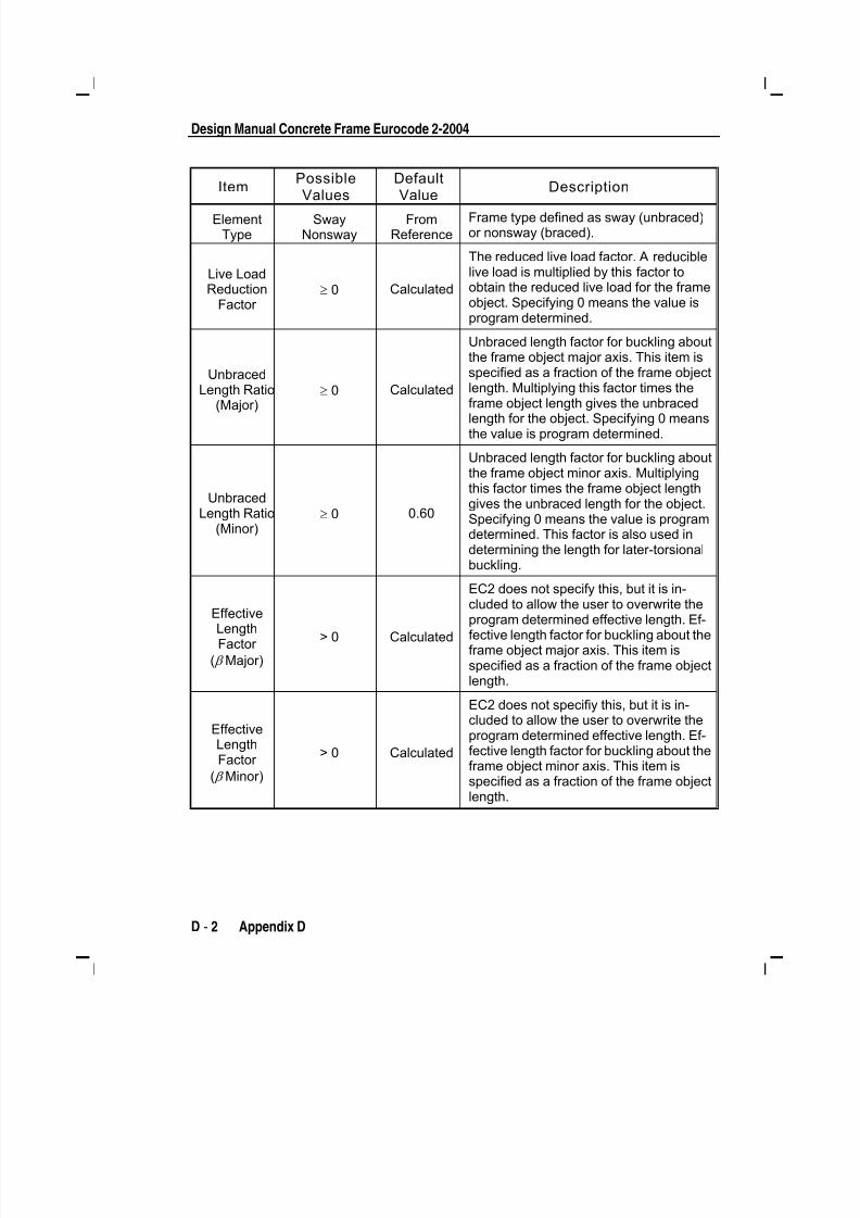
5/11/2018 53078408-CFD-Eurocode-2-2004 - slidepdf.com
http://slidepdf.com/reader/full/53078408-cfd-eurocode-2-2004 74/83
Design Manual Concrete Frame Eurocode 2-2004
D - 2 Appendix D
ItemPossible
Values
Default
Value
Description
ElementType
SwayNonsway
FromReference
Frame type defined as sway (unbraced)or nonsway (braced).
Live LoadReduction
Factor ≥ 0 Calculated
The reduced live load factor. A reduciblelive load is multiplied by this factor toobtain the reduced live load for the frameobject. Specifying 0 means the value isprogram determined.
UnbracedLength Ratio
(Major)
≥ 0 Calculated
Unbraced length factor for buckling aboutthe frame object major axis. This item isspecified as a fraction of the frame objectlength. Multiplying this factor times the
frame object length gives the unbracedlength for the object. Specifying 0 meansthe value is program determined.
UnbracedLength Ratio
(Minor)≥ 0 0.60
Unbraced length factor for buckling aboutthe frame object minor axis. Multiplyingthis factor times the frame object lengthgives the unbraced length for the object.Specifying 0 means the value is programdetermined. This factor is also used indetermining the length for later-torsionalbuckling.
EffectiveLengthFactor
( β Major)
> 0 Calculated
EC2 does not specify this, but it is in-
cluded to allow the user to overwrite theprogram determined effective length. Ef-fective length factor for buckling about theframe object major axis. This item isspecified as a fraction of the frame objectlength.
EffectiveLengthFactor
( β Minor)
> 0 Calculated
EC2 does not specifiy this, but it is in-cluded to allow the user to overwrite theprogram determined effective length. Ef-fective length factor for buckling about theframe object minor axis. This item isspecified as a fraction of the frame objectlength.
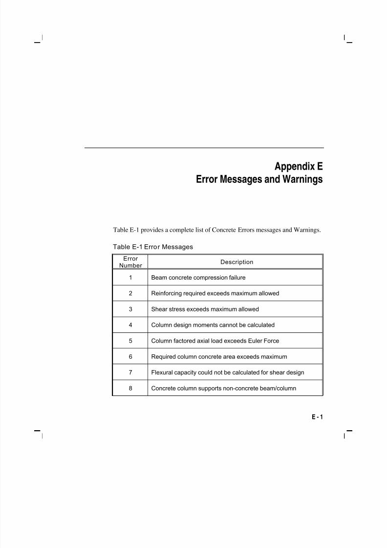
5/11/2018 53078408-CFD-Eurocode-2-2004 - slidepdf.com
http://slidepdf.com/reader/full/53078408-cfd-eurocode-2-2004 75/83
E - 1
Appendix E
Error Messages and Warnings
Table E-1 provides a complete list of Concrete Errors messages and Warnings.
Table E-1 Error Messages
ErrorNumber
Description
1 Beam concrete compression failure
2 Reinforcing required exceeds maximum allowed
3 Shear stress exceeds maximum allowed
4 Column design moments cannot be calculated
5 Column factored axial load exceeds Euler Force
6 Required column concrete area exceeds maximum
7 Flexural capacity could not be calculated for shear design
8 Concrete column supports non-concrete beam/column
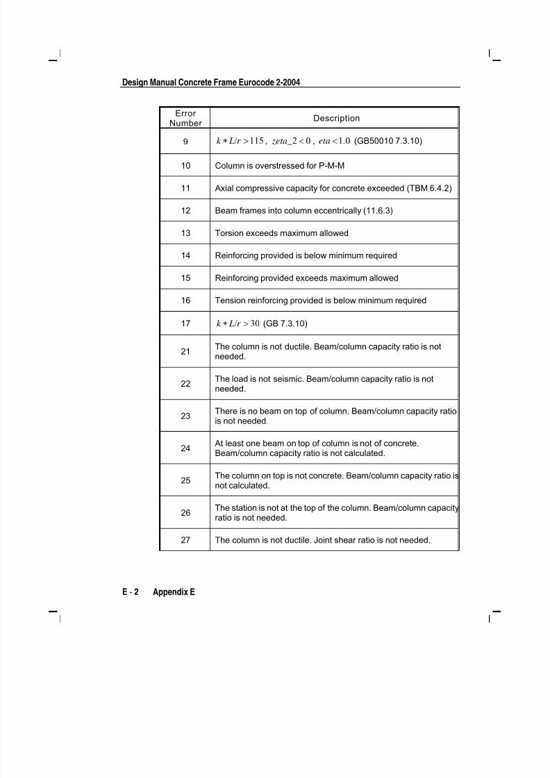
5/11/2018 53078408-CFD-Eurocode-2-2004 - slidepdf.com
http://slidepdf.com/reader/full/53078408-cfd-eurocode-2-2004 76/83
Design Manual Concrete Frame Eurocode 2-2004
E - 2 Appendix E
ErrorNumber
Description
9 115∗ / >k L r , 2 0< zeta_ , 1 0< .eta (GB50010 7.3.10)
10 Column is overstressed for P-M-M
11 Axial compressive capacity for concrete exceeded (TBM 6.4.2)
12 Beam frames into column eccentrically (11.6.3)
13 Torsion exceeds maximum allowed
14 Reinforcing provided is below minimum required
15 Reinforcing provided exceeds maximum allowed
16 Tension reinforcing provided is below minimum required
17 30∗ / >k L r (GB 7.3.10)
21The column is not ductile. Beam/column capacity ratio is notneeded.
22The load is not seismic. Beam/column capacity ratio is not
needed.
23There is no beam on top of column. Beam/column capacity ratiois not needed.
24At least one beam on top of column is not of concrete.Beam/column capacity ratio is not calculated.
25The column on top is not concrete. Beam/column capacity ratio isnot calculated.
26The station is not at the top of the column. Beam/column capacity
ratio is not needed.
27 The column is not ductile. Joint shear ratio is not needed.
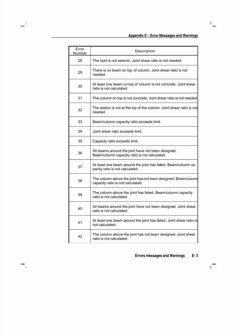
5/11/2018 53078408-CFD-Eurocode-2-2004 - slidepdf.com
http://slidepdf.com/reader/full/53078408-cfd-eurocode-2-2004 77/83
Appendix E – Error Messages and Warnings
Errors messages and Warnings E- 3
ErrorNumber
Description
28 The load is not seismic. Joint shear ratio is not needed.
29There is no beam on top of column. Joint shear ratio is notneeded.
30At least one beam on top of column is not concrete. Joint shear ratio is not calculated.
31 The column on top is not concrete. Joint shear ratio is not needed.
32
The station is not at the top of the column. Joint shear ratio is not
needed.
33 Beam/column capacity ratio exceeds limit.
34 Joint shear ratio exceeds limit.
35 Capacity ratio exceeds limit.
36All beams around the joint have not been designed.Beam/column capacity ratio is not calculated.
37
At least one beam around the joint has failed. Beam/column ca-
pacity ratio is not calculated.
38The column above the joint has not been designed. Beam/columncapacity ratio is not calculated.
39The column above the joint has failed. Beam/column capacityratio is not calculated.
40All beams around the joint have not been designed. Joint shear ratio is not calculated.
41
At least one beam around the joint has failed. Joint shear ratio is
not calculated.
42The column above the joint has not been designed. Joint shear ratio is not calculated.

5/11/2018 53078408-CFD-Eurocode-2-2004 - slidepdf.com
http://slidepdf.com/reader/full/53078408-cfd-eurocode-2-2004 78/83
Design Manual Concrete Frame Eurocode 2-2004
E - 4 Appendix E
ErrorNumber
Description
43The column above the joint has failed. Joint shear ratio is notcalculated.
45Shear stress due to shear force and torsion together exceedsmaximum allowed.
5/11/2018 53078408-CFD-Eurocode-2-2004 - slidepdf.com
http://slidepdf.com/reader/full/53078408-cfd-eurocode-2-2004 79/83
F - 1
Appendix F
Nationally Determined Parameters (NDPs)
The Comité Européen de Normalisation (CEN) version of Eurocode 2-2004
specifies a set of clauses in the design code, for which Nationally Determined
Parameters (NDPs) are permitted to be adjusted by each member country
within their National Annex. Variations in these parameters between countries
are considered in the program by choosing the desired country from the Op-
tions menu > Preferences > Concrete Frame Design command. This appen-
dix lists the NDPs as adopted in the program for the CEN Default version of
the design code. Additional tables are provided that list the NDPs that differ
from the CEN Default values for each country supported in the program.
Table F-1 CEN Default NDPs
NDP Clause Value
γc 2.4.2.4(1) 1.5
γs 2.4.2.4(1) 1.15

5/11/2018 53078408-CFD-Eurocode-2-2004 - slidepdf.com
http://slidepdf.com/reader/full/53078408-cfd-eurocode-2-2004 80/83
Design Manual Concrete Frame Eurocode 2-2004
F - 2 Appendix F
NDP Clause Value
αcc 3.1.6(1) 1.0
αct 3.1.6(2) 1.0
Max f yk 3.2.2(3) 600MPa
Load
Combinations5.1.3(1) Combinations from Eq. 6.10
θ0 5.2(5) 0.005
k 1 5.5(4) 0.44
k 2 5.5(4) 1.25(0.6 + 0.0014/ εcu2)
k 3 5.5(4) 0.54
k 4 5.5(4) 1.25(0.6 + 0.0014/ εcu2)
λlim 5.8.3.1(1) nC B A / 20 ⋅⋅⋅
Second Order
Analysis Method5.8.5(1) Nominal Curvature
CRd,c 6.2.2(1) 0.18/ γc
vmin 6.2.2(1) 0.035k 3/2f ck 1/2
k 1 6.2.2(1) 0.15
θ 6.2.3(2) 45 degrees
ν1 6.2.3(3) ⎥⎦
⎤⎢⎣
⎡−
25016.0 ck f
5/11/2018 53078408-CFD-Eurocode-2-2004 - slidepdf.com
http://slidepdf.com/reader/full/53078408-cfd-eurocode-2-2004 81/83
Appendix F – Nationally Determined Parameters
Appendix F F- 3
NDP Clause Value
αcw
6.2.3(3) 1.0
Beam As,min
9.2.1.1(1) d bd b f
f t t
yk
ctm 0013.026.0 ≥
Beam As,max
9.2.1.1(3) 0.04Ac
Beam ρw,min
9.2.2(5) ) yk ck f f / 08.0
Column As,min
9.5.2(2) c
yd
Ed A f
N 002.0
10.0≥
Column As,max
9.5.2(3) 0.04Ac
αlcc
11.3.5(1) 0.85
αlct
11.3.5(2) 0.85
ClRd,c
11.6.1(1) 0.15/ γc
vl,min
11.6.1(1) 0.30k 3/2
f lck
1/2
k 1
11.6.1(1) 0.15
ν1 11.6.2(1) 0.5η
1(1 – f
ck /250)
Table F-2 United Kingdom NDPs
NDP Clause Value
ψ0,i (wind load) EC0 Combos 0.5
αcc 3.1.6(1) 0.85
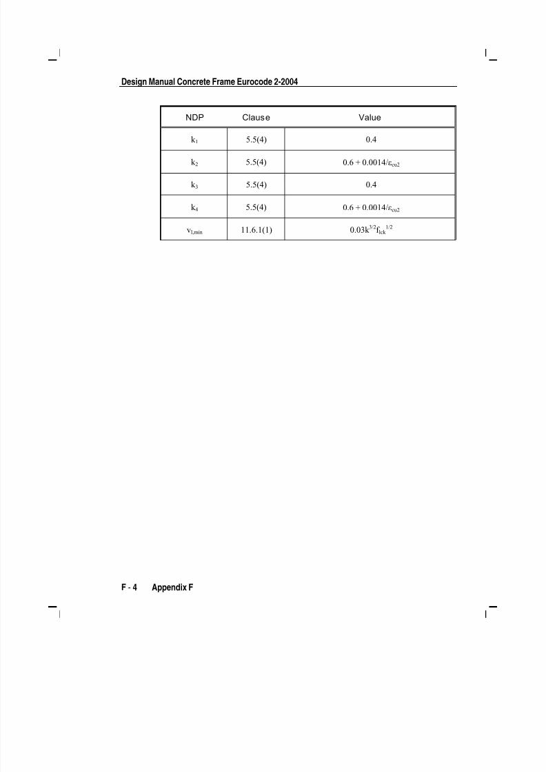
5/11/2018 53078408-CFD-Eurocode-2-2004 - slidepdf.com
http://slidepdf.com/reader/full/53078408-cfd-eurocode-2-2004 82/83
Design Manual Concrete Frame Eurocode 2-2004
F - 4 Appendix F
NDP Clause Value
k 1 5.5(4) 0.4
k 2 5.5(4) 0.6 + 0.0014/ εcu2
k 3 5.5(4) 0.4
k 4 5.5(4) 0.6 + 0.0014/ εcu2
vl,min 11.6.1(1) 0.03k 3/2f lck 1/2

5/11/2018 53078408-CFD-Eurocode-2-2004 - slidepdf.com
http://slidepdf.com/reader/full/53078408-cfd-eurocode-2-2004 83/83
References - i
References
EC2, 2004. Eurocode 2: Design of Concrete Structures – Part 1-1: General
Rules and Rules for Buildings (EN 1992-1-1), European Committee for
Standardization, rue de Stassart, 36, B-1050 Brussels.
CSI, 2006a. SAP2000 Getting Started, Computers and Structures, Inc., Berke-
ley, California.
CSI, 2005a. Welcome to ETABS,, Computers and Structures, Inc., Berkeley,
California.
CSI, 2005b. CSI Analysis Reference Manual, Computers and Structures, Inc.,
Berkeley, California.


![CSP00138[GEN-Tutorial]Pushover Analysis as Per Eurocode 8 2004](https://img.pdfslide.net/doc/110x75/577ccf9f1a28ab9e7890326b/csp00138gen-tutorialpushover-analysis-as-per-eurocode-8-2004.jpg)