Embed Size (px)
Citation preview
532 IEEE TRANSACTIONS ON ELECTROMAGNETIC COMPATIBILITY, VOL. 51, NO. 3, AUGUST 2009
Lightning Electromagnetic Field Coupling toOverhead Lines: Theory, Numerical Simulations,
and Experimental ValidationMario Paolone, Member, IEEE, Farhad Rachidi, Senior Member, IEEE, Alberto Borghetti, Senior Member, IEEE,
Carlo Alberto Nucci, Fellow, IEEE, Marcos Rubinstein, Member, IEEE, Vladimir A. Rakov, Fellow, IEEE,and Martin A. Uman, Fellow, IEEE
(Invited Paper)
Abstract—The evaluation of electromagnetic transients in over-head power lines due to nearby lightning return strokes requiresaccurate models for the calculation of both the incident lightningelectromagnetic pulse (LEMP) and the effects of coupling of thisfield to the line conductors. Considering also the complexity ofdistribution networks in terms of their topology and the presenceof power system components and protection devices, the imple-mentation of the LEMP-to-transmission-line coupling models intosoftware tools used to represent the transient behavior of the entirenetwork is of crucial importance. This paper reviews the most sig-nificant results obtained by the authors concerning the calculationof lightning-induced voltages. First, the theoretical basis of ad-vanced models for the calculation of LEMP-originated transientsin overhead power lines is illustrated; then, the relevant experi-mental validation using: 1) reduced-scale setups with LEMP andnuclear electromagnetic pulse (NEMP) simulators and 2) full-scalesetups illuminated by artificially initiated lightning are reported.Finally, the paper presents comparisons between simulations andnew experimental data consisting of measured natural lightning-induced voltages on a real distribution network in northern Italy,correlated with data from lightning location systems.
Index Terms—Electromagnetic transients, electromagnetic tran-sient program (EMTP), insulation coordination, lightning-inducedtransients, power quality.
I. INTRODUCTION
THE ACCURATE evaluation of lightning-induced over-voltages on distribution networks is essential for: 1) the
estimation of the lightning performance curves of overhead
Manuscript received October 17, 2008; revised March 9, 2009. Firstpublished August 7, 2009; current version published August 21, 2009. Thiswork was supported in part by the Swiss National Science Foundation underGrant 200021-122457 and by the Centro Elettrotecnico Sperimentale Italiano(CESI) and Italian National Research Council (CNR).
M. Paolone, A. Borghetti, and C. A. Nucci are with the Departmentof Electrical Engineering, University of Bologna, Bologna 40124, Italy(e-mail: [email protected]; [email protected]; [email protected]).
F. Rachidi is with the Ecole Polytechnique Federale de Lausanne, LausanneCH-1015, Switzerland (e-mail: [email protected]).
M. Rubinstein is with the School of Engineering and Management of theCanton of Vaud, University of Applied Sciences of Western Switzerland, Dele-mont CH-2800, Switzerland (e-mail: [email protected]).
V. A. Rakov and M. A. Uman are with the Department of Electrical and Com-puter Engineering, University of Florida, Gainesville, FL 32611 USA (e-mail:[email protected]; [email protected]).
Digital Object Identifier 10.1109/TEMC.2009.2025958
lines [1]–[3]; 2) the optimal choice of the characteristics, num-ber, and location of protective/mitigation devices (surge ar-resters, shielding wires, and relevant groundings) [1], [4]–[7];and 3) the analysis of possible correlations between lightningevents—detected by lightning location systems—and voltagedips and/or interruptions [8]–[13].
Transients in overhead power lines due to lightning can becaused by both direct and indirect events [1]. However, in viewof the modest height of medium and low voltage distributionlines compared to that of structures in their vicinity, indirectlightning return strokes are much more frequent events thandirect strokes [14], and for this reason, although direct strokeshave a high probability of producing an insulation flashover, thepaper focuses on indirect lightning events as they are the morefrequent ones.
Concerning the calculation of indirect lightning-induced tran-sients, two approaches are proposed in the literature. The firstis based on the use of approximate analytical formulas, whilethe second is based on the numerical calculation of the lightningelectromagnetic pulse (LEMP) and its electromagnetic couplingwith the overhead line conductors.
As opposed to simple analytical formulas (such as the popularformula by Rusck [15] and the one proposed by Darveniza [16]),which are restricted to unrealistically simple configurations,more elaborate models (e.g., see [17]–[19]) allow for an ac-curate treatment of realistic line and network configurations.The complexity of these models calls for an implementationinto computer codes since, in general, they require a numericalintegration of the relevant equations.
There is also an approach based on the finite-difference time-domain (FDTD) method for solving the Maxwell’s equations(e.g., see [20] and [21]) but it has been applied only to simpleconfiguration lines.
This paper deals with the theoretical basis of advanced mod-els for the calculation of lightning-induced voltages on realisticoverhead distribution networks. The paper also describes thenumerical implementation of these models together with theirvalidation carried out by using experimental data obtained bymeans of reduced-scale setups with LEMP and nuclear electro-magnetic pulse (NEMP) simulators and also with data obtainedby using natural and artificially initiated triggered lightning onfull-scale installations and distribution networks.
0018-9375/$26.00 © 2009 IEEE
Authorized licensed use limited to: University of Florida. Downloaded on May 23,2010 at 19:45:37 UTC from IEEE Xplore. Restrictions apply.
PAOLONE et al.: LIGHTNING ELECTROMAGNETIC FIELD COUPLING TO OVERHEAD LINES 533
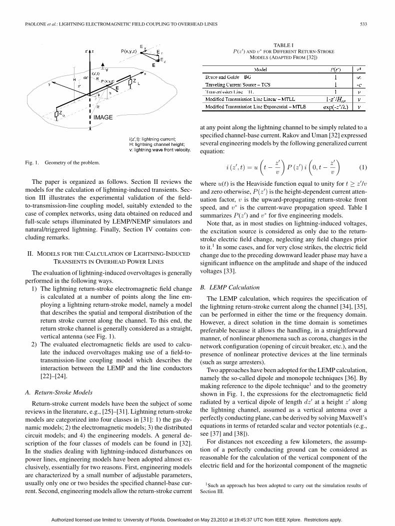
Fig. 1. Geometry of the problem.
The paper is organized as follows. Section II reviews themodels for the calculation of lightning-induced transients. Sec-tion III illustrates the experimental validation of the field-to-transmission-line coupling model, suitably extended to thecase of complex networks, using data obtained on reduced andfull-scale setups illuminated by LEMP/NEMP simulators andnatural/triggered lightning. Finally, Section IV contains con-cluding remarks.
II. MODELS FOR THE CALCULATION OF LIGHTNING-INDUCED
TRANSIENTS IN OVERHEAD POWER LINES
The evaluation of lightning-induced overvoltages is generallyperformed in the following ways.
1) The lightning return-stroke electromagnetic field changeis calculated at a number of points along the line em-ploying a lightning return-stroke model, namely a modelthat describes the spatial and temporal distribution of thereturn stroke current along the channel. To this end, thereturn stroke channel is generally considered as a straight,vertical antenna (see Fig. 1).
2) The evaluated electromagnetic fields are used to calcu-late the induced overvoltages making use of a field-to-transmission-line coupling model which describes theinteraction between the LEMP and the line conductors[22]–[24].
A. Return-Stroke Models
Return-stroke current models have been the subject of somereviews in the literature, e.g., [25]–[31]. Lightning return-strokemodels are categorized into four classes in [31]: 1) the gas dy-namic models; 2) the electromagnetic models; 3) the distributedcircuit models; and 4) the engineering models. A general de-scription of the four classes of models can be found in [32].In the studies dealing with lightning-induced disturbances onpower lines, engineering models have been adopted almost ex-clusively, essentially for two reasons. First, engineering modelsare characterized by a small number of adjustable parameters,usually only one or two besides the specified channel-base cur-rent. Second, engineering models allow the return-stroke current
TABLE IP (z ′) AND v∗ FOR DIFFERENT RETURN-STROKE
MODELS (ADAPTED FROM [32])
at any point along the lightning channel to be simply related to aspecified channel-base current. Rakov and Uman [32] expressedseveral engineering models by the following generalized currentequation:
i (z′, t) = u
(t − z′
v
)P (z′) i
(0, t − z′
v
)(1)
where u(t) is the Heaviside function equal to unity for t ≥ z′/vand zero otherwise, P (z′) is the height-dependent current atten-uation factor, v is the upward-propagating return-stroke frontspeed, and v∗ is the current-wave propagation speed. Table Isummarizes P (z′) and v∗ for five engineering models.
Note that, as in most studies on lightning-induced voltages,the excitation source is considered as only due to the return-stroke electric field change, neglecting any field changes priorto it.1 In some cases, and for very close strikes, the electric fieldchange due to the preceding downward leader phase may have asignificant influence on the amplitude and shape of the inducedvoltages [33].
B. LEMP Calculation
The LEMP calculation, which requires the specification ofthe lightning return-stroke current along the channel [34], [35],can be performed in either the time or the frequency domain.However, a direct solution in the time domain is sometimespreferable because it allows the handling, in a straightforwardmanner, of nonlinear phenomena such as corona, changes in thenetwork configuration (opening of circuit breaker, etc.), and thepresence of nonlinear protective devices at the line terminals(such as surge arresters).
Two approaches have been adopted for the LEMP calculation,namely the so-called dipole and monopole techniques [36]. Bymaking reference to the dipole technique1 and to the geometryshown in Fig. 1, the expressions for the electromagnetic fieldradiated by a vertical dipole of length dz′ at a height z′ alongthe lightning channel, assumed as a vertical antenna over aperfectly conducting plane, can be derived by solving Maxwell’sequations in terms of retarded scalar and vector potentials (e.g.,see [37] and [38]).
For distances not exceeding a few kilometers, the assump-tion of a perfectly conducting ground can be considered asreasonable for the calculation of the vertical component of theelectric field and for the horizontal component of the magnetic
1Such an approach has been adopted to carry out the simulation results ofSection III.
Authorized licensed use limited to: University of Florida. Downloaded on May 23,2010 at 19:45:37 UTC from IEEE Xplore. Restrictions apply.
534 IEEE TRANSACTIONS ON ELECTROMAGNETIC COMPATIBILITY, VOL. 51, NO. 3, AUGUST 2009
field [39], [40]. On the other hand, the horizontal component ofthe electric field is appreciably affected by the finite conductiv-ity of the ground. Although the intensity of the horizontal fieldcomponent is generally much smaller than that of the verticalone, within the context of certain coupling models, it plays animportant role in the coupling mechanism [41] and, hence, ithas to be determined accurately. Methods for the calculationof the horizontal field using the exact Sommerfeld integrals areinefficient from the point of view of computer time, althoughdedicated algorithms have been proposed in some recent stud-ies [42]. A simplified expression has been proposed indepen-dently by Rubinstein [43] and Cooray [44], which is discussedby Wait [45] and improved by Cooray [46]. It has been shownthat the Cooray–Rubinstein formula is able to reproduce sat-isfactorily the horizontal electric field at close, intermediate,and distant ranges and for typical ground conductivities (e.g.,see [47] and [48]).2
Note finally that, as discussed in [49], LEMP calculationcan also be performed using numerical solutions of Maxwell’sequations. Two methods have been widely used for this purpose,namely the method of moment (e.g., see [50]–[54]) and theFDTD technique (e.g., see [55]–[58]).
C. Field-to-Transmission-Line Coupling Equations
To solve the coupling problem, i.e., the determination of volt-ages and currents induced by an external field on a conductingsystem, use could be made of antenna theory, the general andrigorous approach based on Maxwell’s equations [59]. Due tothe length of typical overhead line installations, together withthe need for also modeling other components (e.g., power trans-formers, surge arresters, general line terminations), the use ofsuch theory for the calculation of lightning-induced overvolt-ages is not straightforward and implies long computing times.
Another possible approach is the use of the transmission-linetheory. The basic assumptions of this approximation are that theresponse of the line is quasitransverse electromagnetic (quasi-TEM) and that the transverse dimensions of the line are muchsmaller than the minimum significant wavelength. The line isrepresented by an infinite series of elementary sections to which,by virtue of the earlier assumptions, the quasistatic approxima-tion applies. Each section is illuminated progressively by theincident electromagnetic field so that longitudinal propagationeffects are taken into account.
Different and equivalent coupling models based on the useof the transmission-line approach have been proposed in theliterature (e.g., see [22]–[24]) and, in what follows, we shallmake reference to the Agrawal et al. coupling model [23]. Thatmodel presents the notable advantage of taking into accountin a straightforward way the ground resistivity in the couplingmechanism and it is the only one that has been thoroughly testedand validated using experimental results, as will be discussednext.
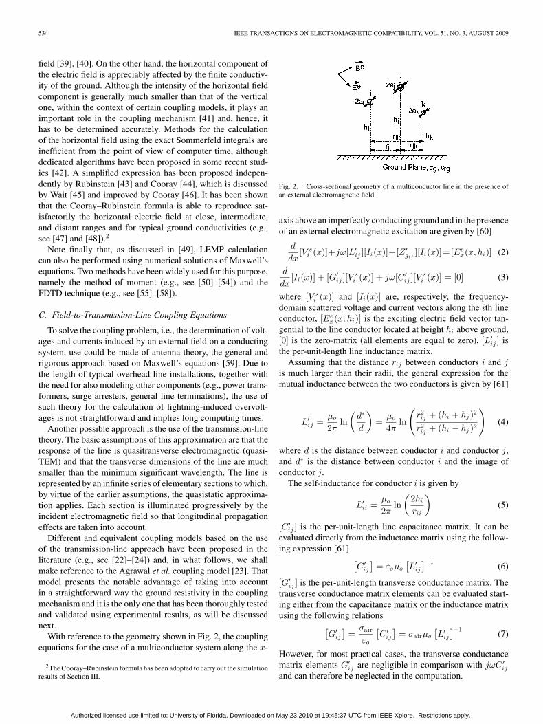
With reference to the geometry shown in Fig. 2, the couplingequations for the case of a multiconductor system along the x-
2The Cooray–Rubinstein formula has been adopted to carry out the simulationresults of Section III.
Fig. 2. Cross-sectional geometry of a multiconductor line in the presence ofan external electromagnetic field.
axis above an imperfectly conducting ground and in the presenceof an external electromagnetic excitation are given by [60]
d
dx[V s
i (x)]+jω[L′ij ][Ii(x)]+[Z ′
gi j][Ii(x)]=[Ee
x(x, hi)] (2)
d
dx[Ii(x)] + [G′
ij ][Vsi (x)] + jω[C ′
ij ][Vsi (x)] = [0] (3)
where [V si (x)] and [Ii(x)] are, respectively, the frequency-
domain scattered voltage and current vectors along the ith lineconductor, [Ee
x(x, hi)] is the exciting electric field vector tan-gential to the line conductor located at height hi above ground,[0] is the zero-matrix (all elements are equal to zero), [L′
ij ] isthe per-unit-length line inductance matrix.
Assuming that the distance rij between conductors i and jis much larger than their radii, the general expression for themutual inductance between the two conductors is given by [61]
L′ij =
µo
2πln
(d∗
d
)=
µo
4πln
(r2ij + (hi + hj )2
r2ij + (hi − hj )2
)(4)
where d is the distance between conductor i and conductor j,and d∗ is the distance between conductor i and the image ofconductor j.
The self-inductance for conductor i is given by
L′ii =
µo
2πln
(2hi
rii
)(5)
[C ′ij ] is the per-unit-length line capacitance matrix. It can be
evaluated directly from the inductance matrix using the follow-ing expression [61] [
C ′ij
]= εoµo
[L′
ij
]−1(6)
[G′ij ] is the per-unit-length transverse conductance matrix. The
transverse conductance matrix elements can be evaluated start-ing either from the capacitance matrix or the inductance matrixusing the following relations[
G′ij
]=
σair
εo
[C ′
ij
]= σairµo
[L′
ij
]−1(7)
However, for most practical cases, the transverse conductancematrix elements G′
ij are negligible in comparison with jωC ′ij
and can therefore be neglected in the computation.
Authorized licensed use limited to: University of Florida. Downloaded on May 23,2010 at 19:45:37 UTC from IEEE Xplore. Restrictions apply.
PAOLONE et al.: LIGHTNING ELECTROMAGNETIC FIELD COUPLING TO OVERHEAD LINES 535
Finally, [Z ′gi j
] is the ground impedance matrix. The generalexpression for the mutual ground impedance between two con-ductors i and j derived by Sunde is given by [62]
Z ′gi j
=jωµo
π
∫ ∞
0
e−(hi +hj )x√x2 + γ2
g + xcos(rijx) dx. (8)
In a similar way as for the case of a single-wire line, an accu-rate logarithmic approximation has been proposed by Rachidiet al. [60], which is given by
Z ′gi j
∼= jωµo
4πln
[(1 + γg ((hi + hj )/2))2 + (γgrij /2)2
(γg ((hi + hj )/2))2 + (γgrij /2)2
].
(9)Note that, in (2) and (3), the terms corresponding to the wire
impedance and the so-called ground admittance have been ne-glected. Indeed, for typical overhead lines and for the typicalfrequency range of interest (below 10 MHz), disregarding theseparameters is a reasonable approximation [47], [63].
The boundary conditions for the two line terminations in thecase of lumped linear impedances are given by
[V si (0)] = −[ZA ][Ii(0)] +
[∫ hi
0Ee
z (0, z)dz
](10)
[V si (L)] = [ZB ][Ii(L)] +
[∫ hi
0Ee
z (L, z)dz
]. (11)
A time-domain representation of coupling equations issometimes preferable, as explained in Section II-B. How-ever, frequency-dependent parameters, such as the groundimpedance, need to be represented using convolution inte-grals, which require considerable computation time and memorystorage.
The two transmission-line coupling equations of the modelof Agrawal et al., expressed in the time domain for a multicon-ductor overhead line above a lossy ground are
∂
∂x[vs
i (x, t)] +[L′
ij
] ∂
∂t[ii(x, t)]
+ [ξ′gi j] ⊗ ∂
∂t[ii(x, t)] = [Ee
x(x, hi, t)] (12)
∂
∂x[ii(x, t)] +
[C ′
ij
] ∂
∂t[vs
i (x, t)] = 0. (13)
Here, ⊗ denotes the convolution product and the elements ofthe matrix [ξ′gi j
] are given by the inverse Fourier transform ofthe ground impedance matrix [Z ′
gi j]
[ξ′gi j] = F−1
Z ′
gi , j
jω
. (14)
The general expression for the ground impedance matrixterms in the frequency domain does not have an analytical in-verse Fourier transform. Thus, the elements of the transientground resistance matrix in time domain have to be, in general,determined using a numerical inverse Fourier transform algo-rithm. However, the following analytical expressions have beenshown to be reasonable approximations to the numerical values
obtained using an inverse fast Fourier transform (FFT) [64]:
ξgi i= min
1
2πhi
õ0
ε0εrg,
µ0
πτgi i
[1
2√
π
√τgi i
t
+14
exp(τgi i
t
)erfc
(√τgi i
t
)− 1
4
](15)
ξgi j= min
1
2πh
õ0
ε0εrg,
µ0
πTij
×[
12√
π
√Tij
tcos
(θij
2
)+
14
exp(
Tij cos (θij )t
)
× cos(
Tij
tsin(θij )−θij
)− 1
2√
π
∞∑n=0
αn
(Tij
t
)(2n+1)/2
× cos(
2n + 12
θij
)− cos (θij )
4
](16)
in which
τgi i= h2
i µ0σg (17)
and Tij and θij are defined as follows:
τgi j= h2
ij µ0σg =(
hi + hj
2+ j
rij
2
)2
µ0σg = Tij ejθi j (18)
and erfc is the complementary error function.Similar expressions have also been proposed by Araneo and
Cellozi [65]. More discussion on the validity of the approximateanalytical expressions can be found in [66].
D. FDTD Numerical Solution of Field-to-Transmission-LineCoupling Equations
As mentioned earlier, most studies on lightning-induced volt-ages on overhead power lines use a direct time-domain analysisbecause of its relative simplicity in dealing with insulation co-ordination problems and because of its ability to handle nonlin-earities that arise in presence of protective devices such as surgearresters or the corona effect.
One of the most popular approaches to solve the couplingequations in the time domain is the FDTD technique (e.g., see[67]).
Such a technique was already used by Agrawal et al. [23]where partial time and space derivatives were approximatedusing a first-order FDTD scheme. Instead, the use of a second-order FDTD scheme based on the Lax–Wendroff algorithm [69],[70] was proposed in [68]. The second-order FDTD schemeshows much better stability compared to its first-order coun-terpart, especially when analyzing complex systems involvingnonlinearities [68], [71].
Authorized licensed use limited to: University of Florida. Downloaded on May 23,2010 at 19:45:37 UTC from IEEE Xplore. Restrictions apply.
536 IEEE TRANSACTIONS ON ELECTROMAGNETIC COMPATIBILITY, VOL. 51, NO. 3, AUGUST 2009
The second-order discretized solutions for the line currentand scattered voltage are given by
[vi ]n+1k = [vi ]
nk − ∆t
[C ′
ij
]−1(
[ii ]nk+1 − [ii ]
nk−1
2∆x
)
− ∆t2
2[[
L′ij
] [C ′
ij
]]−1
×(
[Ehi ]nk+1 − [Ehi ]
nk−1
2∆x
−[vi ]
nk+1 + [vi ]
nk−1 − 2 [vi ]
nk
∆x2
)
+∆t2
2[[
L′ij
] [C ′
ij
]]−1
([v′
gi
]n
k+1−
[v′
gi
]n
k−1
2∆x
)
(19)
[ii ]n+1k = [ii ]
nk − ∆t
[L′
ij
]−1(
[vi ]nk+1 − [vi ]
nk−1
2∆x
− [Ehi ]nk +
[v′
gi
]n
k
)
+∆t2
2[[
C ′ij
] [L′
ij
]]−1(
[ii ]nk+1 +[ii ]
nk−1 − 2 [ii ]
nk
∆x2
)
+∆t2
2[[
C ′ij
] [L′
ij
]]−1
([C ′
ij
][Ehi ]n+1k −[Ehi ]
n−1k
2∆t
)
− ∆t2
2[[
C ′ij
] [L′
ij
]]−1
([C ′
ij
] [v′
gi
]n
k−
[v′
gi
]n−1k
∆t
)
(20)where ∆x is the spatial integration step, ∆t is the time integra-tion step, k = 0, 1, 2, . . ., kmax is the spatial discretization index(kmax = (L/∆x) + 1, where L is the line length), n = 0, 1, 2,. . ., nmax is the time discretization index (nmax = (T/∆t) + 1,where T is the adopted time window), [vi ]
n+1k is the vector
of the scattered voltages corresponding to the spatial and timeintegration indexes k and n + 1, respectively, [ii ]
n+1k is the
vector of the conductors currents corresponding to the spatialand time integration indexes k and n + 1, respectively, and[v′
gi ]nk =
∑nh=0 [ξ′gi j
]n−hk ([ii ]kn − [ii ]kn−1)/∆t.
E. Extension to Complex Networks
As mentioned in Section I, the inherent complexity of dis-tribution networks in terms of topology and the presence ofdifferent components and protection devices, calls for an exten-sion of LEMP-to-transmission-line coupling models initiallydeveloped for a single line.
The LEMP-to-transmission-line coupling equations deal withthe case of multiconductor lines with resistive terminations. Inprinciple, such a model can be suitably modified, case by case,in order to take into account the presence of the specific type ofterminations, line discontinuities (e.g., surge arresters across theline insulators along the line), and of complex system topolo-gies. This procedure requires that the boundary conditions forthe transmission-line coupling equations be properly rewritten
case by case, as discussed by Nucci et al. [72]. However, as pro-posed by other authors [18], [19], [72]–[80], it has been foundmore convenient to link such a model with the electromagnetictransient program (EMTP) in order to take advantage of thelarge available library of power components.
The approach adopted in this paper is the one illustratedby Nucci et al. [72], Paolone [71], Borghetti et al. [19], andrecently improved by Napolitano et al. [79] in which the LEMP-coupled network is viewed as an illuminated group of linesconnected to each other through shunt admittances. The LEMP-to-transmission-line coupling model computes the response ofthe various lines composing the network, while the EMTP solvesthe boundary condition.
III. EXPERIMENTAL VALIDATION
Rigorously, testing a coupling model requires the knowledgeof the incident electromagnetic field and of the induced voltagesor currents induced by the field on a given experimental line. Thefields and voltages need to be obtained experimentally. Usingthe measured exciting incident field as an input to the couplingmodel under test, one has to evaluate the voltage or currentinduced on the line as predicted by the model and to comparethe resulting calculated wave shape with the measured one.
A number of experimental installations have been set up indifferent research centers in the world with such an aim. Theexciting field can come from different sources, such as the fieldradiated by natural or triggered lightning [81]–[89], by NEMPsimulators [19], [90]–[93], or by vertical antennas simulating areduced-scale lightning channel [94]–[96].
As a general comment, it can be observed that the use oflightning is complicated by the intrinsic difficulty in performinga controlled experiment, although triggered lightning is clearlya better technique in this respect. More controlled conditionscan be achieved using the aforementioned EMP simulators orreduced-scale models. In what follows we give a brief descrip-tion of the results that have been obtained using these techniqueswith the aim of testing the coupling models.
A. Reduced-Scale Model Tests by Means of NEMP andLEMP Simulators
As known, a NEMP simulator is a facility able to radiatewithin its so-called working volume an electromagnetic wavewith very short rise time (of the order of some nanoseconds)and with electric field intensity of some tens of kilovolts permeter. The main components of an EMP simulator are a pulsegenerator and an antenna (of guided-wave type, conical, etc.)excited by the generator. With an EMP simulator it is possible,in principle, to avoid contaminations of the incident field dueto wire scattering, as might be the case when the field and theinduced voltages are measured simultaneously (e.g., for linesilluminated by natural lightning fields). In this respect, the re-peatability of the pulse generator output is crucial, in that theelectromagnetic field that is measured within the working vol-ume in absence of the victim must be essentially unaltered whenthe victim is put within the working volume.
Authorized licensed use limited to: University of Florida. Downloaded on May 23,2010 at 19:45:37 UTC from IEEE Xplore. Restrictions apply.
PAOLONE et al.: LIGHTNING ELECTROMAGNETIC FIELD COUPLING TO OVERHEAD LINES 537
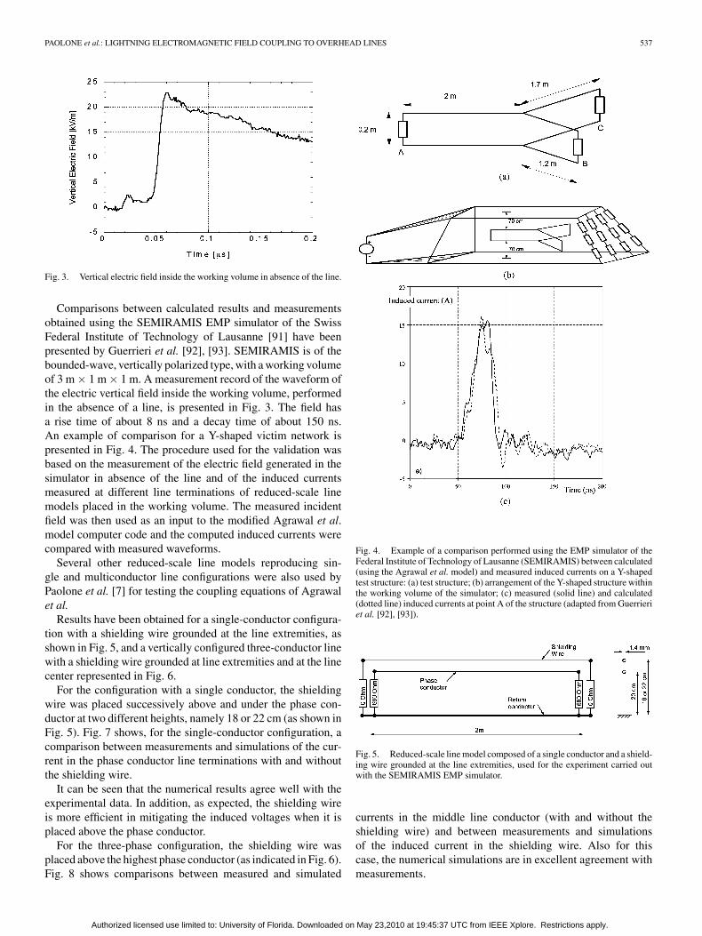
Fig. 3. Vertical electric field inside the working volume in absence of the line.
Comparisons between calculated results and measurementsobtained using the SEMIRAMIS EMP simulator of the SwissFederal Institute of Technology of Lausanne [91] have beenpresented by Guerrieri et al. [92], [93]. SEMIRAMIS is of thebounded-wave, vertically polarized type, with a working volumeof 3 m × 1 m × 1 m. A measurement record of the waveform ofthe electric vertical field inside the working volume, performedin the absence of a line, is presented in Fig. 3. The field hasa rise time of about 8 ns and a decay time of about 150 ns.An example of comparison for a Y-shaped victim network ispresented in Fig. 4. The procedure used for the validation wasbased on the measurement of the electric field generated in thesimulator in absence of the line and of the induced currentsmeasured at different line terminations of reduced-scale linemodels placed in the working volume. The measured incidentfield was then used as an input to the modified Agrawal et al.model computer code and the computed induced currents werecompared with measured waveforms.
Several other reduced-scale line models reproducing sin-gle and multiconductor line configurations were also used byPaolone et al. [7] for testing the coupling equations of Agrawalet al.
Results have been obtained for a single-conductor configura-tion with a shielding wire grounded at the line extremities, asshown in Fig. 5, and a vertically configured three-conductor linewith a shielding wire grounded at line extremities and at the linecenter represented in Fig. 6.
For the configuration with a single conductor, the shieldingwire was placed successively above and under the phase con-ductor at two different heights, namely 18 or 22 cm (as shown inFig. 5). Fig. 7 shows, for the single-conductor configuration, acomparison between measurements and simulations of the cur-rent in the phase conductor line terminations with and withoutthe shielding wire.
It can be seen that the numerical results agree well with theexperimental data. In addition, as expected, the shielding wireis more efficient in mitigating the induced voltages when it isplaced above the phase conductor.
For the three-phase configuration, the shielding wire wasplaced above the highest phase conductor (as indicated in Fig. 6).Fig. 8 shows comparisons between measured and simulated
Fig. 4. Example of a comparison performed using the EMP simulator of theFederal Institute of Technology of Lausanne (SEMIRAMIS) between calculated(using the Agrawal et al. model) and measured induced currents on a Y-shapedtest structure: (a) test structure; (b) arrangement of the Y-shaped structure withinthe working volume of the simulator; (c) measured (solid line) and calculated(dotted line) induced currents at point A of the structure (adapted from Guerrieriet al. [92], [93]).
Fig. 5. Reduced-scale line model composed of a single conductor and a shield-ing wire grounded at the line extremities, used for the experiment carried outwith the SEMIRAMIS EMP simulator.
currents in the middle line conductor (with and without theshielding wire) and between measurements and simulationsof the induced current in the shielding wire. Also for thiscase, the numerical simulations are in excellent agreement withmeasurements.
Authorized licensed use limited to: University of Florida. Downloaded on May 23,2010 at 19:45:37 UTC from IEEE Xplore. Restrictions apply.
538 IEEE TRANSACTIONS ON ELECTROMAGNETIC COMPATIBILITY, VOL. 51, NO. 3, AUGUST 2009
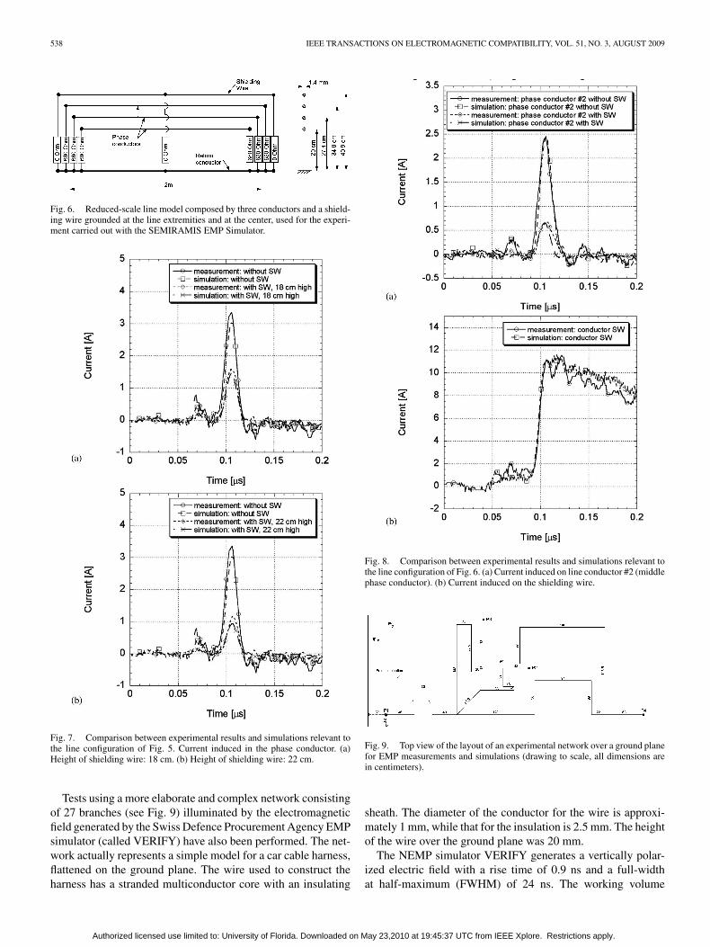
Fig. 6. Reduced-scale line model composed by three conductors and a shield-ing wire grounded at the line extremities and at the center, used for the experi-ment carried out with the SEMIRAMIS EMP Simulator.
Fig. 7. Comparison between experimental results and simulations relevant tothe line configuration of Fig. 5. Current induced in the phase conductor. (a)Height of shielding wire: 18 cm. (b) Height of shielding wire: 22 cm.
Tests using a more elaborate and complex network consistingof 27 branches (see Fig. 9) illuminated by the electromagneticfield generated by the Swiss Defence Procurement Agency EMPsimulator (called VERIFY) have also been performed. The net-work actually represents a simple model for a car cable harness,flattened on the ground plane. The wire used to construct theharness has a stranded multiconductor core with an insulating
Fig. 8. Comparison between experimental results and simulations relevant tothe line configuration of Fig. 6. (a) Current induced on line conductor #2 (middlephase conductor). (b) Current induced on the shielding wire.
Fig. 9. Top view of the layout of an experimental network over a ground planefor EMP measurements and simulations (drawing to scale, all dimensions arein centimeters).
sheath. The diameter of the conductor for the wire is approxi-mately 1 mm, while that for the insulation is 2.5 mm. The heightof the wire over the ground plane was 20 mm.
The NEMP simulator VERIFY generates a vertically polar-ized electric field with a rise time of 0.9 ns and a full-widthat half-maximum (FWHM) of 24 ns. The working volume
Authorized licensed use limited to: University of Florida. Downloaded on May 23,2010 at 19:45:37 UTC from IEEE Xplore. Restrictions apply.
PAOLONE et al.: LIGHTNING ELECTROMAGNETIC FIELD COUPLING TO OVERHEAD LINES 539
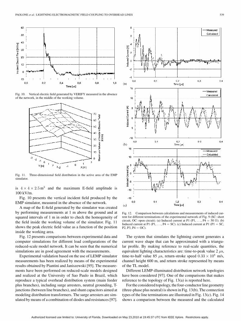
Fig. 10. Vertical electric field generated by VERIFY measured in the absenceof the network, in the middle of the working volume.
Fig. 11. Three-dimensional field distribution in the active area of the EMPsimulator.
is 4 × 4 × 2.5 m3 and the maximum E-field amplitude is100 kV/m.
Fig. 10 presents the vertical incident field produced by theEMP simulator, measured in the absence of the network.
A map of the E-field generated by the simulator was createdby performing measurements at 1 m above the ground and atsquared intervals of 1 m in order to check the homogeneity ofthe field inside the working volume of the simulator. Fig. 11shows the peak electric field value as a function of the positioninside the working area.
Fig. 12 presents comparisons between experimental data andcomputer simulations for different load configurations of thereduced-scale model network. It can be seen that the numericalsimulations are in good agreement with the measurements.
Experimental validation based on the use of LEMP simulatormeasurements has been realized by means of the experimentalresults obtained by Piantini and Janiszewski [95]. The measure-ments have been performed on reduced-scale models designedand realized at the University of Sao Paulo in Brazil, whichreproduce a typical overhead distribution system (main feederplus branches), including surge arresters, neutral grounding, T-junctions (between line branches), and shunt capacitors aimed atmodeling distribution transformers. The surge arresters are sim-ulated by means of a combination of diodes and resistances [97].
Fig. 12. Comparison between calculations and measurements of induced cur-rent for different terminations of the experimental network of Fig. 9 (SC: shortcircuit, OC: open circuit). (a) Induced current at P1 (P1, . . ., P4 = 50 Ω). (b)Induced current at P1 (P1, . . ., P4 = SC). (c) Induced current at P1 (P1 = SC,P2, P3, P4 = OC).
The system that simulates the lightning current generates acurrent wave shape that can be approximated with a triangu-lar profile. By making reference to real-scale quantities, theequivalent lighting characteristics are: time-to-peak value 2 µs,time-to-half value 85 µs, return-stroke speed 0.33 × 10⁸ m/s,channel height 600 m, and return stroke represented by meansof the TL model.
Different LEMP-illuminated distribution network topologieshave been considered [97]. One of the comparisons that makesreference to the topology of Fig. 13(a) is reported here.
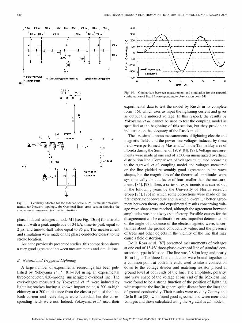
For the considered topology, the four-conductor line geometry(three-phase plus neutral) is shown in Fig. 13(b). The connectiontypes of the line terminations are illustrated in Fig. 13(c). Fig. 14shows a comparison between the measured and the calculated
Authorized licensed use limited to: University of Florida. Downloaded on May 23,2010 at 19:45:37 UTC from IEEE Xplore. Restrictions apply.
540 IEEE TRANSACTIONS ON ELECTROMAGNETIC COMPATIBILITY, VOL. 51, NO. 3, AUGUST 2009
Fig. 13. Geometry adopted for the reduced-scale LEMP simulator measure-ments. (a) Network topology. (b) Overhead lines cross section showing theconductors arrangement. (c) Line terminations.
phase induced voltages at node M1 [see Fig. 13(a)] for a strokecurrent with a peak amplitude of 34 kA, time-to-peak equal to2 µs, and time-to-half value equal to 85 µs. The measurementand simulation were made on the phase conductor closest to thestroke location.
As in the previously presented studies, this comparison showsa very good agreement between measurements and simulations.
B. Natural and Triggered Lightning
A large number of experimental recordings has been pub-lished by Yokoyama et al. [81]–[83] using an experimentalthree-conductor, 820-m-long, unenergized overhead line. Theovervoltages measured by Yokoyama et al. were induced bylightning strokes having a known impact point, a 200-m-highchimney at a 200 m distance from the closest point of the line.Both current and overvoltages were recorded, but the corre-sponding fields were not. Indeed, Yokoyama et al. used their
Fig. 14. Comparison between measurement and simulation for the networkconfiguration of Fig. 13 corresponding to observation point M1.
experimental data to test the model by Rusck in its completeform [15], which uses as input the lightning current and givesas output the induced voltage. In this respect, the results byYokoyama et al. cannot be used to test the coupling model asspecified at the beginning of this section, but they provide anindication on the adequacy of the Rusck model.
The first simultaneous measurements of lightning electric andmagnetic fields, and the power-line voltages induced by thesefields were performed by Master et al. in the Tampa Bay area ofFlorida during the Summer of 1979 [84], [98]. Voltage measure-ments were made at one end of a 500-m unenergized overheaddistribution line. Comparison of voltages calculated accordingto the Agrawal et al. coupling model and voltages measuredon the line yielded reasonably good agreement in the waveshapes, but the magnitudes of the theoretical amplitudes weresystematically about a factor of four smaller than the measure-ments [84], [98]. Then, a series of experiments was carried outin the following years by the University of Florida researchgroup [85], [86] in which some corrections were made on thefirst experiment procedure and in which, overall, a better agree-ment between theory and experimental results concerning volt-age wave shapes was reached, although the agreement betweenamplitudes was not always satisfactory. Possible causes for thedisagreement can be calibration errors, imperfect determinationof the angle of incidence of the electromagnetic wave, uncer-tainties about the ground conductivity value, and the presenceof trees and other objects in the vicinity of the line that maycause a field distortion.
De la Rosa et al. [87] presented measurements of voltagesat one end of 13-kV three-phase overhead line of standard con-struction type in Mexico. The line was 2.8 km long and nearly10 m high. The three line conductors were bound together toa common point at both line ends, used to take a connectiondown to the voltage divider and matching resistor placed atground level at both ends of the line. The amplitude, polarity,and wave shape of the voltage at one end of the Mexican linewere found to be a strong function of the position of lightningwith respect to the line (in general quite distant from the line) andof ground conductivity. Their results were used by Cooray andDe la Rosa [88], who found good agreement between measuredvoltages and those calculated using the Agrawal et al. model.
Authorized licensed use limited to: University of Florida. Downloaded on May 23,2010 at 19:45:37 UTC from IEEE Xplore. Restrictions apply.
PAOLONE et al.: LIGHTNING ELECTROMAGNETIC FIELD COUPLING TO OVERHEAD LINES 541
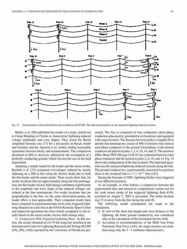
Fig. 15. Experimental overhead distribution line installed at the ICLRT. The indicated quantities are the measured lightning-induced currents.
Barker et al. [89] published the results of a study carried outat Camp Blanding in Florida to characterize lightning-inducedvoltage amplitudes and wave shapes. They tested the Ruscksimplified formula (see [17] for a discussion on Rusck modeland formula) and the Agrawal et al. model, finding reasonableagreement between theory and measurements. The comparisonpresented in [89] is, however, affected by the assumption of aperfectly conducting ground, which was not the case in the fieldexperiment.
Adopting a simple model for the leader and the return stroke,Rachidi et al. [33] computed overvoltages induced by nearbylightning on a 500 m line using the electric fields due to boththe dart leader and the return stroke. Their results show that, forstroke locations that are approximately along the line prolonga-tion, the dart leader electric field change contributes significantlyto the amplitude and wave shape of the induced voltages cal-culated at the line terminations. For stroke locations that areperpendicular to the line, for the same observation points, theleader effect is less appreciable. Their computed results havebeen compared to experimental data from close triggered light-ning obtained on a test line at the NASA Kennedy Space Centerand improved agreement has been found (compared to the re-sults based on the return-stroke electric field change only).
1) Comparison With Triggered Lightning Data: In this sec-tion, the results obtained on a 0.75-km-long line installed at theInternational Center for Lightning Research and Testing (ICLRT[29], [99], [100]) operated by the University of Florida are pre-
sented. The line is composed of four conductors (three-phaseconductors plus neutral, grounded at six locations) and equippedwith surge arresters. The distance between poles is roughly 60 mand the line terminations consist of 500-Ω resistors that connecteach phase conductor to the ground. Groundings of the neutralconductor are placed at poles 1, 2, 6, 10, 14, and 15. The arresters(Ohio-Brass PDV100 type 213615) are connected between eachphase conductor and the neutral at poles 2, 6, 10, and 14. Fig. 15shows the configuration of the line in detail. The indicated quan-tities are the measured lightning-induced currents along the line.The ground conductivity, experimentally measured in a positionclose to the overhead line is 1.7 × 10⁻³ S/m [101].
During the Summer of 2003, lightning flashes were triggeredat two different positions.
As an example, in what follows a comparison between theexperimental data and numerical computations carried out forthe sixth return stroke of the triggered lightning flash #336,recorded on August 2, 2003 is presented. The strike locationwas 15 m away from the line facing the pole #4.
The following model assumptions are made in thesimulations.
1) In view of the short line length and close distance to thelightning, the finite ground conductivity was consideredonly in the calculation of the horizontal electric field.
2) According to recommendations of the IEEE Fast FrontTransients Task Force [102], the surge arresters are mod-eled using only the V –I nonlinear characteristics.
Authorized licensed use limited to: University of Florida. Downloaded on May 23,2010 at 19:45:37 UTC from IEEE Xplore. Restrictions apply.
542 IEEE TRANSACTIONS ON ELECTROMAGNETIC COMPATIBILITY, VOL. 51, NO. 3, AUGUST 2009
The groundings of the neutral conductors, composed of ver-tical cylindrical rods are modeled adopting a lumped parameterapproach [62], [103]–[105]. The geometrical data adopted to in-fer the parameters of this model are the ones reported in [106].
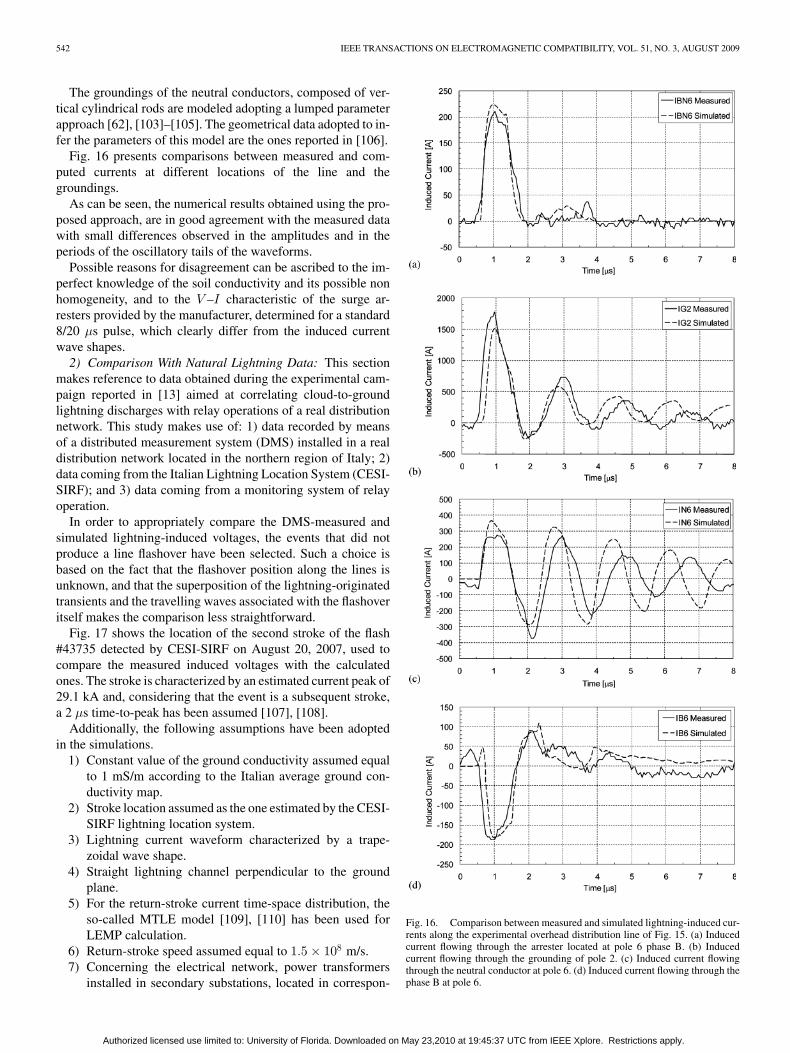
Fig. 16 presents comparisons between measured and com-puted currents at different locations of the line and thegroundings.
As can be seen, the numerical results obtained using the pro-posed approach, are in good agreement with the measured datawith small differences observed in the amplitudes and in theperiods of the oscillatory tails of the waveforms.
Possible reasons for disagreement can be ascribed to the im-perfect knowledge of the soil conductivity and its possible nonhomogeneity, and to the V –I characteristic of the surge ar-resters provided by the manufacturer, determined for a standard8/20 µs pulse, which clearly differ from the induced currentwave shapes.
2) Comparison With Natural Lightning Data: This sectionmakes reference to data obtained during the experimental cam-paign reported in [13] aimed at correlating cloud-to-groundlightning discharges with relay operations of a real distributionnetwork. This study makes use of: 1) data recorded by meansof a distributed measurement system (DMS) installed in a realdistribution network located in the northern region of Italy; 2)data coming from the Italian Lightning Location System (CESI-SIRF); and 3) data coming from a monitoring system of relayoperation.
In order to appropriately compare the DMS-measured andsimulated lightning-induced voltages, the events that did notproduce a line flashover have been selected. Such a choice isbased on the fact that the flashover position along the lines isunknown, and that the superposition of the lightning-originatedtransients and the travelling waves associated with the flashoveritself makes the comparison less straightforward.
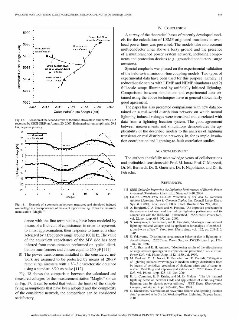
Fig. 17 shows the location of the second stroke of the flash#43735 detected by CESI-SIRF on August 20, 2007, used tocompare the measured induced voltages with the calculatedones. The stroke is characterized by an estimated current peak of29.1 kA and, considering that the event is a subsequent stroke,a 2 µs time-to-peak has been assumed [107], [108].
Additionally, the following assumptions have been adoptedin the simulations.
1) Constant value of the ground conductivity assumed equalto 1 mS/m according to the Italian average ground con-ductivity map.
2) Stroke location assumed as the one estimated by the CESI-SIRF lightning location system.
3) Lightning current waveform characterized by a trape-zoidal wave shape.
4) Straight lightning channel perpendicular to the groundplane.
5) For the return-stroke current time-space distribution, theso-called MTLE model [109], [110] has been used forLEMP calculation.
6) Return-stroke speed assumed equal to 1.5 × 10⁸ m/s.7) Concerning the electrical network, power transformers
installed in secondary substations, located in correspon-
Fig. 16. Comparison between measured and simulated lightning-induced cur-rents along the experimental overhead distribution line of Fig. 15. (a) Inducedcurrent flowing through the arrester located at pole 6 phase B. (b) Inducedcurrent flowing through the grounding of pole 2. (c) Induced current flowingthrough the neutral conductor at pole 6. (d) Induced current flowing through thephase B at pole 6.
Authorized licensed use limited to: University of Florida. Downloaded on May 23,2010 at 19:45:37 UTC from IEEE Xplore. Restrictions apply.
PAOLONE et al.: LIGHTNING ELECTROMAGNETIC FIELD COUPLING TO OVERHEAD LINES 543
Fig. 17. Location of the second stroke of the three-stroke flash number #43 735recorded by CESI-SIRF on August 20, 2007. Estimated current amplitude: 29.1kA, negative polarity.
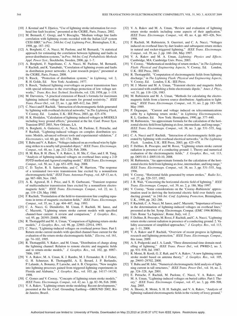
Fig. 18. Example of a comparison between measured and simulated inducedovervoltage in correspondence of the event reported in Fig. 17 for the measure-ment station “Maglio.”
dence with the line terminations, have been modeled bymeans of a Π circuit of capacitances in order to represent,to a first approximation, their response to transients char-acterized by a frequency range around 100 kHz. The valueof the equivalent capacitance of the MV side has beeninferred from measurements performed on typical distri-bution transformers and chosen equal to 250 pF [111].
8) The power transformers installed in the considered net-work are assumed to be protected by means of 20-kVrated surge arresters with a V –I characteristic obtainedusing a standard 8/20 µs pulse [112].
Fig. 18 shows the comparison between the calculated andmeasured voltages for the measurement station “Maglio” shownin Fig. 17. It can be noted that within the limits of the simpli-fying assumptions that have been adopted and the complexityof the considered network, the comparison can be consideredsatisfactory.
IV. CONCLUSION
A survey of the theoretical bases of recently developed mod-els for the calculation of LEMP-originated transients in over-head power lines was presented. The models take into accountmulticonductor lines above a lossy ground and the presenceof a multibranched power system network, including compo-nents and protection devices (e.g., grounded conductors, surgearresters).
Special emphasis was placed on the experimental validationof the field-to-transmission-line coupling models. Two types ofexperimental data have been used for this purpose, namely: 1)reduced-scale setups with LEMP and NEMP simulators and 2)full-scale setups illuminated by artificially initiated lightning.Comparisons between simulations and experimental data ob-tained using the above techniques have in general shown fairlygood agreement.
The paper has also presented comparisons with new data ob-tained on a real-world distribution network on which naturallightning-induced voltages were measured and correlated withdata from a lightning location system. The good agreementbetween measurements and simulations demonstrates the ap-plicability of the described models to the analysis of lightningtransients on real distribution networks, in, for example, insula-tion coordination and lightning-to-fault correlation studies.
ACKNOWLEDGMENT
The authors thankfully acknowledge years of collaborationsand profitable discussions with Prof. M. Ianoz, Prof. C. Mazzetti,Dr. M. Bernardi, Dr. S. Guerrieri, Dr. F. Napolitano, and Dr. E.Petrache.
REFERENCES
[1] IEEE Guide for Improving the Lightning Performance of Electric PowerOverhead Distribution Lines, IEEE Standard 1410, 2004.
[2] CIGRE-CIRED JWG C4.4.02: Protection of MV and LV NetworksAgainst Lightning. Part I: Common Topics, Int. Council Large Electr.Syst. (CIGRE), Paris, France, CIGRE Tech. Brochure No. 287, 2006.
[3] A. Borghetti, C. A. Nucci, and M. Paolone, “An improved procedure forthe assessment of overhead line indirect lightning performance and itscomparison with the IEEE Std. 1410 method,” IEEE Trans. Power Del.,vol. 22, no. 1, pp. 684–692, Jan. 2007.
[4] S. Yokoyama, K. Yamamoto, and H. Kinoshita, “Analogue simulation oflightning induced voltages and its application for analysis of overhead-ground-wire effects,” Proc. Inst. Electr. Eng., vol. 132, pp. 208–216,1985.
[5] S. Yokoyama, “Distribution surge arrester behavior due to lightning in-duced voltages,” IEEE Trans. Power Del., vol. PWRD-1, no. 1, pp. 171–178, Jan. 1986.
[6] T. A. Short and R. H. Ammon, “Monitoring results of the effectivenessof surge arrester spacings on distribution line protection,” IEEE Trans.Power Del., vol. 14, no. 3, pp. 1142–1150, Jul. 1999.
[7] M. Paolone, C. A. Nucci, E. Petrache, and F. Rachidi, “Mitigationof lightning-induced overvoltages in medium voltage distribution linesby means of periodical grounding of shielding wires and of surge ar-resters: Modelling and experimental validation,” IEEE Trans. PowerDel., vol. 19, no. 1, pp. 423–431, Jan. 2004.
[8] K. L. Cummins, E. P. Krider, and M. D. Malone, “The US nationallightning detection network (TM) and applications of cloud-to-groundlightning data by electric power utilities,” IEEE Trans. Electromagn.Compat., vol. 40, no. 4, pp. 465–480, Nov. 1998.
[9] G. Diendorfer, “Correlation of power line failures and lightning locationdata,” presented at the 5th Int. Workshop Phys. Lightning, Nagoya, Japan,2001.
Authorized licensed use limited to: University of Florida. Downloaded on May 23,2010 at 19:45:37 UTC from IEEE Xplore. Restrictions apply.
544 IEEE TRANSACTIONS ON ELECTROMAGNETIC COMPATIBILITY, VOL. 51, NO. 3, AUGUST 2009
[10] J. Kosmac and V. Djurica, “Use of lightning stroke information for over-head line fault location,” presented at the CIGRE, Paris, France, 2002.
[11] M. Bernardi, C. Giorgi, and V. Biscaglia, “Medium voltage line faultscorrelation with lightning events recorded with the Italian LLP systemCESI-SIRF,” in Proc. 24th Int. Conf. Lightning Prot., Birmingham, U.K.,1998, pp. 187–192.
[12] A. Borghetti, C. A. Nucci, M. Paolone, and M. Bernardi, “A statisticalapproach for estimating the correlation between lightning and faults inpower distribution systems,” in Proc. 9th Int. Conf. Probabilistic MethodsAppl. Power Syst., Stockholm, Sweden, 2006, pp. 1–7.
[13] A. Borghetti, F. Napolitano, C. A. Nucci, M. Paolone, M. Bernardi,F. Rachidi, and K. Yamabuki, “Correlation of lightning events and faultsin distribution power networks: A joint research project,” presented atthe CIGRE, Paris, France, 2008.
[14] S. Rusck, “Protection of distribution systems,” in Lightning, vol. 2,R. H. Golde, Ed. New York: Academic, 1977.
[15] S. Rusck, “Induced lightning overvoltages on power transmission lineswith special reference to the overvoltage protection of low voltage net-works,” Trans. Roy. Inst. Technol. Stockholm, vol. 120, 1958, pp. 1–118.
[16] M. Darveniza, “A practical extension of Rusck’s formula for maximumlightning induced voltage that accounts for ground resistivity,” IEEETrans. Power Del., vol. 22, no. 1, pp. 605–612, Jan. 2007.
[17] C. Nucci and F. Rachidi, “Interaction of electromagnetic fields generatedby lightning with overhead electrical networks,” in The Lightning Flash,V. Cooray, Ed. London, U.K.: IEE Press, 2003, pp. 425–478.
[18] H. K. Hoidalen, “Calculation of lightning-induced voltages in MODELSincluding lossy ground effects,” presented at the Int. Conf. Power Syst.Transient IPST 2003, New Orleans, LA.
[19] A. Borghetti, A. Gutierrez, C. A. Nucci, M. Paolone, E. Petrache, andF. Rachidi, “Lightning-induced voltages on complex distribution sys-tems: Models, advanced software tools and experimental validation,” J.Electrostatics, vol. 60, pp. 163–174, 2004.
[20] Y. Baba and V. A. Rakov, “Voltages induced on an overhead wire by light-ning strikes to a nearby tall grounded object,” IEEE Trans. Electromagn.Compat., vol. 48, no. 1, pp. 212–224, Feb. 2006.
[21] H. M. Ren, B. H. Zhou, V. A. Rakov, L. H. Shi, C. Gao, and J. H. Yang,“Analysis of lightning-induced voltages on overhead lines using a 2-DFDTD method and Agrawal coupling model,” IEEE Trans. Electromagn.Compat., vol. 50, no. 3, pp. 651–659, Aug. 2008.
[22] C. D. Taylor, R. S. Satterwhite, and C. W. Harrison, “The responseof a terminated two-wire transmission line excited by a nonuniformelectromagnetic field,” IEEE Trans. Antennas Propag., vol. AP-13, no. 6,pp. 987–989, Nov. 1965.
[23] A. K. Agrawal, H. J. Price, and S. H. Gurbaxani, “Transient responseof multiconductor transmission lines excited by a nonuniform electro-magnetic field,” IEEE Trans. Electromagn. Compat., vol. 22, no. 2,pp. 119–129, May 1980.
[24] F. Rachidi, “Formulation of the field-to-transmission line coupling equa-tions in terms of magnetic excitation fields,” IEEE Trans. Electromagn.Compat., vol. 35, no. 3, pp. 404–407, Aug. 1993.
[25] C. A. Nucci, G. Diendorfer, M. Uman, F. Rachidi, M. Ianoz, andC. Mazzetti, “Lightning return stroke current models with specifiedchannel-base current: A review and comparison,” J. Geophys. Res.,vol. 95, pp. 20395–20408, 1990.
[26] R. Thottappillil and M. A. Uman, “Comparison of lightning return-strokemodels,” J. Geophys. Res., vol. 98, pp. 22903–22914, 1993.
[27] C. Nucci, “Lightning-induced voltages on overhead power lines. Part I:Return stroke current models with specified channel-base current for theevaluation of the return stroke electromagnetic fields,” Electra, vol. 161,pp. 74–102, 1995.
[28] R. Thottappillil, V. Rakov, and M. Uman, “Distribution of charge alongthe lightning channel: Relation to remote electric and magnetic fieldsand to return-stroke models,” J. Geophys. Res., vol. 102, pp. 6987–7006, 1997.
[29] V. A. Rakov, M. A. Uman, K. J. Rambo, M. I. Fernandez, R. J. Fisher,G. H. Schnetzer, R. Thottappillil, A. E. Berard, J. P. Berlandis,P. Lalande, A. Bonamy, P. Laroche, and A. B. Clergeries, “New insightsinto lightning processes gained from triggered-lightning experiments inFlorida and Alabama,” J. Geophys. Res., vol. 103, pp. 14117–14130,1998.
[30] C. Gomes and V. Cooray, “Concepts of lightning return stroke models,”IEEE Trans. Electromagn. Compat., vol. 42, no. 1, pp. 82–96, Feb. 2000.
[31] V. A. Rakov, “Lightning return stroke modeling: Recent developments,”presented at the Int. Conf. Grounding Earthing—GROUND 2002, Riode Janeiro, Brazil.
[32] V. A. Rakov and M. A. Uman, “Review and evaluation of lightningreturn stroke models including some aspects of their application,”IEEE Trans. Electromagn. Compat., vol. 40, no. 4, pp. 403–426, Nov.1998.
[33] F. Rachidi, M. Rubinstein, S. Guerrieri, and C. A. Nucci, “Voltagesinduced on overhead lines by dart leaders and subsequent return strokesin natural and rocket-triggered lightning,” IEEE Trans. Electromagn.Compat., vol. 39, no. 2, pp. 160–166, May 1997.
[34] V. A. Rakov and M. A. Uman, Lightning: Physics and Effects.Cambridge, MA: Cambridge Univ. Press, 2003.
[35] V. Cooray, “Mathematical modeling of return strokes,” in The LightningFlash: Physical and Engineering Aspects, V. Cooray, Ed. London,U.K.: IEE Press, 2003.
[36] R. Thottappillil, “Computation of electromagnetic fields from lightningdischarge,” in The Lightning Flash: Physical and Engineering Aspects,V. Cooray, Ed. London, U.K.: IEE Press.
[37] M. J. Master and M. A. Uman, “Transient electric and magnetic fieldsassociated with establishing a finite electrostatic dipole,” Amer. J. Phys.,vol. 51, pp. 118–126, 1983.
[38] M. Rubinstein and M. A. Uman, “Methods for calculating the electro-magnetic fields from a known source distribution: Application to light-ning,” IEEE Trans. Electromagn. Compat., vol. 31, no. 2, pp. 183–189,May 1989.
[39] P. Degauque, “Current and voltage induced on telecommunicationscable by a lightning return stroke,” in Lightning Electromagnetics,R. L. Gardner, Ed. New York: Hemisphere, 1990, pp. 377–440.
[40] M. Rubinstein, “An approximate formula for the calculation of the hori-zontal electric field from lightning at close, intermediate, and long range,”IEEE Trans. Electromagn. Compat., vol. 38, no. 3, pp. 531–535, Aug.1996.
[41] C. A. Nucci and F. Rachidi, “Interaction of electromagnetic fields gen-erated by lightning with overhead electrical networks,” in The LightningFlash. London, U.K.: IEE Press, 2003, pp. 425–478.
[42] F. Delfino, R. Procopio, and M. Rossi, “Lightning return stroke currentradiation in presence of a conducting ground: 1. Theory and numericalevaluation of the electromagnetic fields,” J. Geophys. Res., vol. 113,pp. D05110-1–D05110-10, 2008.
[43] M. Rubinstein, “An approximate formula for the calculation of the hori-zontal electric field from lightning at close, intermediate, and long range,”IEEE Trans. Electromagn. Compat., vol. 38, no. 3, pp. 531–535, Aug.1996.
[44] V. Cooray, “Horizontal fields generated by return strokes,” Radio Sci.,vol. 27, pp. 529–537, 1992.
[45] J. R. Wait, “Concerning the horizontal electric field of lightning,” IEEETrans. Electromagn. Compat., vol. 39, no. 2, p. 186, May 1997.
[46] V. Cooray, “Some considerations on the ‘Cooray–Rubinstein’ approx-imation used in deriving the horizontal electric field over finitely con-ducting ground,” in 24th Int. Conf. Lightning Protection, Birmingham,U.K., 1998, pp. 282–286.
[47] F. Rachidi, C. A. Nucci, M. Ianoz, and C. Mazzetti, “Importance of lossesin the determination of lightning-induced voltages on overhead lines,”presented at the Int. Symp. Electromagn. Compat. (EMC 1996 ROMA).Univ. Rome ‘La Sapienza’, Rome, Italy, vol. 2.
[48] F. Delfino, R. Procopio, M. Rossi, F. Rachidi, and C. A. Nucci, “Lightningreturn stroke current radiation in presence of a conducting ground: 2. Va-lidity assessment of simplified approaches,” J. Geophys. Res., vol. 113,pp. 1–11, 2008.
[49] V. A. Rakov and F. Rachidi, “Overview of recent progress in lightningresearch and lightning protection,” IEEE Trans. Electromagn. Compat.,this issue, 2009.
[50] A. S. Podgorski and J. A. Landt, “Three dimensional time domain mod-elling of lightning,” IEEE Trans. Power Del., vol. PWRD-2, no. 3,pp. 931–938, Jul. 1987.
[51] R. Moini, B. Kordi, G. Z. Rafi, and V. A. Rakov, “A new lightning returnstroke model based on antenna theory,” J. Geophys. Res., vol. 105,pp. 29693–29702, 2000.
[52] Y. Baba and M. Ishii, “Numerical electromagnetic field analysis of light-ning current in tall structures,” IEEE Trans. Power Del., vol. 16, no. 2,pp. 324–328, Apr. 2001.
[53] E. Petrache, F. Rachidi, M. Paolone, C. Nucci, V. A. Rakov, andM. A. Uman, “Lightning-induced voltages on buried cables. Part I: The-ory,” IEEE Trans. Electromagn. Compat., vol. 47, no. 3, pp. 498–508,Aug. 2005.
[54] A. Shoory, R. Moini, S. H. H. Sadeghi, and V. A. Rakov, “Analysis oflightning-radiated electromagnetic fields in the vicinity of lossy ground,”
Authorized licensed use limited to: University of Florida. Downloaded on May 23,2010 at 19:45:37 UTC from IEEE Xplore. Restrictions apply.
PAOLONE et al.: LIGHTNING ELECTROMAGNETIC FIELD COUPLING TO OVERHEAD LINES 545
IEEE Trans. Electromagn. Compat., vol. 47, no. 1, pp. 131–145, Feb.2005.
[55] C. A. F. Sartori and J. R. Cardoso, “An analytical-FDTD method for nearLEMP calculation,” IEEE Trans. Magn., vol. 36, no. 4, pp. 1631–1634,Jul. 2000.
[56] C. Yang and B. Zhou, “Calculation methods of electromagnetic fieldsvery close to lightning,” IEEE Trans. Electromagn. Compat., vol. 46,no. 1, pp. 133–141, Feb. 2004.
[57] Y. Baba and V. A. Rakov, “On the mechanism of attenuation of cur-rent waves propagating along a vertical perfectly conducting wire aboveground: Application to lightning,” IEEE Trans. Electromagn. Compat.,vol. 47, no. 3, pp. 521–532, Aug. 2005.
[58] A. Mimouni, F. Rachidi, and Z. Azzouz, “A finite-difference time-domainapproach for the evaluation of electromagnetic fields radiated by light-ning to tall structures,” J. Electrostatics, vol. 866, pp. 504–513, 2008.
[59] F. M. Tesche, “Comparison of the transmission line and scattering modelsfor computing the HEMP response of overhead cables,” IEEE Trans.Electromagn. Compat., vol. 34, no. 2, pp. 93–99, May 1992.
[60] F. Rachidi, C. A. Nucci, and M. Ianoz, “Transient analysis of multicon-ductor lines above a lossy ground,” IEEE Trans. Power Del., vol. 14,no. 1, pp. 294–302, Jan. 1999.
[61] F. M. Tesche, M. Ianoz, and T. Karlsson, EMC Ananlysis Methods andComputational Models. New York: Wiley–Interscience, 1997.
[62] E. D. Sunde, Earth Conduction Effects in Transmission Systems. NewYork: Dover, 1968.
[63] F. Rachidi, C. A. Nucci, and I. M. C. Mazzetti, “Influence of a lossyground on lightning-induced voltages on overhead lines,” IEEE Trans.Electromagn. Compat., vol. 38, no. 3, pp. 250–264, Aug. 1996.
[64] F. Rachidi, S. Loyka, C. A. Nucci, and M. Ianoz, “A new expressionfor the ground transient resistance matrix elements of multiconductoroverhead transmission lines,” Electr. Power Syst. Res. J., vol. 65, pp. 41–46, 2003.
[65] R. Araneo and S. Cellozi, “Direct time domain analysis of transmissionlines above a lossy ground,” Inst. Electr. Eng. Proc. Sci. Meas. Technol.,vol. 148, pp. 73–79, 2001.
[66] N. Theethayi and R. Thottappillil, “Surge propagation and crosstalkin multiconductor transmission lines above ground,” in ElectromagneticField Interaction with Transmission Lines. From Classical Theory to HFRadiation Effects, F. Rachidi and S. Tkachenko, Eds. Billerica, MA:WIT Press, 2008.
[67] A. Tafflove, Computational Electrodynamics: The Finite Difference TimeDomain Method. Norwood, MA: Artech House, 1995.
[68] M. Paolone, C. A. Nucci, and F. Rachidi, “A new finite difference timedomain scheme for the evaluation of lightning induced overvoltages onmulticonductor overhead lines,” presented at the 5th Int. Conf. PowerSyst. Transients, Rio de Janeiro, Brazil, 2001.
[69] P. D. Lax and B. Wendroff, “System of conservations laws,” Comm.Pure Appl. Math., vol. 13, pp. 217–237, 1960.
[70] S. R. Omick and S. P. Castillo, “A new finite difference time-domainalgorithm for the accurate modeling of wide-band electromagnetic phe-nomena,” IEEE Trans. Electromagn. Compat., vol. 35, no. 2, pp. 215–222, May 1993.
[71] M. Paolone, “Modeling of lightning-induced voltages on distributionnetworks for the solution of power quality problems, and relevant imple-mentation in a transient program,” Ph.D. dissertation, Dept. Electr. Eng.,Univ. Bologna, Bologna, Italy, 2001, p. 117.
[72] C. A. Nucci, V. Bardazzi, R. Iorio, A. Mansoldo, and A. Porrino, “A codefor the calculation of lightning-induced overvoltages and its interfacewith the electromagnetic transient program,” presented at the 22nd Int.Conf. Lightning Protection (ICLP), Budapest, Hungary, 1994.
[73] D. Orzan, P. Baraton, M. Ianoz, and F. Rachidi, “Comparaison entre deuxapproches pour traiter le couplage entre un champ EM et des reseaux delignes,” presented at the 8eme Colloque Int. sur la Compat. Electromagn.,Lille, France, 1996.
[74] D. Orzan, “Couplage externe et interne entre un champelectromagnetique et un reseau de lignes multifilaires,” Ph.D. thesis,Ecole Polytech. Federale Lausanne, Lausanne, Switzerland, 1998.
[75] H. K. Hoidalen, “Lightning-induced overvoltages in low-voltage sys-tems,” Ph.D. thesis, Norwegian Univ. Sci. Technol., Trondheim, Norway,1997.
[76] H. K. Hoidalen, “Calculation of lightning-induced overvoltages usingMODELS,” presented at the Int. Conf. Power Syst. Transients. Budapest,Hungary, 1999
[77] H. K. Hoidalen, “Analytical formulation of lightning-induced voltageson multiconductor overhead lines above lossy ground,” IEEE Trans.Electromagn. Compat., vol. 45, no. 1, pp. 92–100, Feb. 2003.
[78] E. Perez, A. Delgadillo, D. Urrutia, and H. Torres, “Optimizing the surgearresters location for improving lightning induced voltage performanceof distribution network,” in Proc. IEEE PES Gen. Meeting, 2007, pp. 1–6.
[79] F. Napolitano, A. Borghetti, C. A. Nucci, M. Paolone, F. Rachidi, andJ. Mahserejian, “An advanced interface between the LIOV code andthe EMTP-RV,” presented at the 29th Int. Conf. Lightning Protection(ICLP), Uppsala, Sweden, 2008.
[80] R. Montano, N. Theethayi, and V. Cooray, “An efficient implementationof the Agrawal et al. model for lightning-induced voltage calculationsusing circuit simulation software,” IEEE Trans. Circuits Syst. I: Reg.Papers, vol. 55, no. 9, pp. 2959–2965, Oct. 2008.
[81] S. Yokoyama, K. Miyake, H. Mitani, and A. Takanishi, “Simultane-ous measurement of lightning induced voltages with associated strokecurrents,” IEEE Trans. Power App. Syst., vol. PAS-102, no. 8, pp. 2420–2429, Aug. 1983.
[82] S. Yokoyama, K. Miyake, H. Mitani, and N. Yamazaki, “Advanced obser-vations of lightning induced voltage on power distribution lines,” IEEETrans. Power Del., vol. 1, no. 2, pp. 129–139, Apr. 1986.
[83] S. Yokoyama, K. Miyake, and S. Fukui, “Advanced observations oflighting induced voltages on power distribution lines (II),” IEEE Trans.Power Del., vol. 4, no. 4, pp. 2196–2203, Oct. 1989.
[84] M. J. Master, M. A. Uman, W. Beasley, and M. Darveniza, “Lightninginduced voltages on power lines: Experiment,” IEEE Trans. Power App.Syst., vol. PAS-103, no. 9, pp. 2519–2529, Sep. 1984.
[85] M. Rubinstein, A. Y. Tzeng, M. A. Uman, P. J. Medelius, andE. M. Thomson, “An experimental test of a theory of lightning-inducedvoltages on an overhead wire,” IEEE Trans. Electromagn. Compat.,vol. 31, no. 4, pp. 376–383, Nov. 1989.
[86] N. Georgiadis, M. Rubinstein, M. A. Uman, P. J. Medelius, andE. M. Thomson, “Lightning-induced voltages at both ends of a 448-m power-distribution line,” IEEE Trans. Electromagn. Compat., vol. 34,no. 4, pp. 451–460, Nov. 1992.
[87] F. De la Rosa, R. Valdivia, H. Perez, and J. Loza, “Discussion about theinducing effects of lightning in an experimental power distribution linein Mexico,” IEEE Trans. Power Del., vol. 3, no. 3, pp. 1080–1089, Jul.1988.
[88] V. Cooray and F. De la Rosa, “Shapes and amplitudes of the initialpeaks of lightning-induced voltage in power lines over finitely conductinghearth: Theory and comparison with experiment,” IEEE Trans. AntennasPropag., vol. AP-34, no. 1, pp. 88–92, Jan. 1986.
[89] P. P. Barker, T. A. Short, A. Eybert-Berard, and J. B. Berlandis, “Inducedvoltage measurements on an experimental distribution line during nearbyrocket triggered lightning flashes,” IEEE Trans. Power Del., vol. 11,no. 2, pp. 980–995, Apr. 1996.
[90] C. E. Baum, “EMP Simulators, for various types of nuclear EMP environ-ment: And interim categorization,” IEEE Trans. Electromagn. Compat.,vol. EMC-20, no. 1, pp. 35–53, Feb. 1978.
[91] F. Arreghini, M. Ianoz, P. Zweiacker, D. V. Giri, and A. Tehori, “SEMI-RAMIS: An asymmetrical bounded wave EMP simulator with a goodconfinement inside the transmission line,” presented at the 10th Int.Zurich Symp. Electromagn. Compat., Zurich, Switzerland, 1993.
[92] S. Guerrieri, F. Rachidi, M. Ianoz, P. Zweiacker, A. Borghetti, andC. A. Nucci, “Effet d’une impulsion electro-magnetique sur desreseaux electriques a plusieurs branches. Modelisation et validationexperimentale,” presented at the 7eme Colloque Int. sur la CompatibiliteElectromagnetique, Toulouse, France, 1994.
[93] S. Guerrieri, F. Rachidi, M. Ianoz, P. Zweiacker, and C. A. Nucci, “Atime-domain approach to evaluate induced voltages on tree-shaped elec-trical networks by external electromagnetic fields,” presented at the11th Int. Zurich Symp. Electromagn. Compat., Zurich, Switzerland,1995.
[94] M. Ishii, K. Michishita, Y. Hongo, and S. Ogume, “Lightning-inducedvoltage on an overhead wire dependent on ground conductivity,” IEEETrans. Power Del., vol. 9, no. 1, pp. 109–118, Jan. 1994.
[95] A. Piantini and J. M. Janiszewski, “An experimental study of lightninginduced voltages by means of a scale model,” in Proc. 21st Int. Conf.Lightning Protection (ICLP), Berlin, Germany, 1992, pp. 195–199.
[96] C. A. Nucci, A. Borghetti, A. Piantini, and W. Janischewskyj, “Lightning-induced voltages on distribution overhead lines: Comparison betweenexperimental results from a reduced-scale model and most recentapproaches,” in Proc. 24th Int. Conf. Lightning Protection (ICLP),Birmingham, U.K., 1998, pp. 314–320.
[97] A. Piantini, J. M. Janiszewski, A. Borghetti, C. A. Nucci, and M. Paolone,“A scale model for the study of the LEMP response of complex powerdistribution networks,” IEEE Trans. Power Del., vol. 22, no. 1, pp. 710–720, Jan. 2007.
Authorized licensed use limited to: University of Florida. Downloaded on May 23,2010 at 19:45:37 UTC from IEEE Xplore. Restrictions apply.
546 IEEE TRANSACTIONS ON ELECTROMAGNETIC COMPATIBILITY, VOL. 51, NO. 3, AUGUST 2009
[98] M. J. Master and M. A. Uman, “Lightning induced voltages on powerlines: Theory,” IEEE Trans. Power App. Syst., vol. PAS-103, no. 9,pp. 2502–2518, Sep. 1984.
[99] V. A. Rakov, “Lightning discharges triggered using rocket-and-wire tech-niques,” Recent Res. Devel. Geophys., vol. 2, pp. 141–171, 1999.
[100] V. A. Rakov, M. A. Uman, D. Wang, K. J. Rambo, D. E. Crawford, andG. H. Schnetzer, “Lightning properties from triggered-lightning experi-ments at Camp Blanding, Florida (1997–1999),” in Proc. 25th Int. Conf.Lightning Prot. (ICLP), Rhodes, Greece, 2000, pp. 54–59.
[101] M. Paolone, E. Petrache, F. Rachidi, C. A. Nucci, V. A. Rakov,M. A. Uman, D. Jordan, K. Rambo, J. Jerauld, M. Nyffeler, andJ. Schoene, “Lightning-induced voltages on buried cables. Part II: Ex-periment and model validation,” IEEE Trans. Electromagn. Compat.,vol. 47, no. 3, pp. 498–508, Aug. 2005.
[102] “IEEE Fast Front Transients Task Force: Modeling guidelines for fastfront transients,” IEEE Trans. Power Del., vol. 11, no. 1, pp. 493–506,Jan. 1996.
[103] R. Rudenberg, Electrical Shock Waves in Power System. Cambridge,MA: Harvard Univ. Press, 1968.
[104] S. Bourg, B. Sacepe, and T. Debu, “Deep earth electrodes in highly resis-tive ground: Frequency behavior,” in Proc. IEEE Int. Symp. Electromagn.Compat., 1995, pp. 584–589.
[105] L. Grcev and M. Popov, “On high-frequency circuit equivalents of avertical ground rod,” IEEE Trans. Power Del., vol. 20, no. 2, pp. 1598–1603, Apr. 2005.
[106] C. Mata, “Interaction of lightning with power distribution lines,” Ph.D.thesis, Univ. Florida, Gainesville, 2003.
[107] R. B. Andersson and A. J. Eriksson, “Lightning parameters for engineer-ing application,” Electra, vol. 69, pp. 65–102, 1980.
[108] CIGRE WG 01 of SC 33, “Guide to procedures for estimating the light-ning performance of transmission lines,” Int. Council Large Electr. Syst.(CIGRE), Paris, France, CIGRE Publication 63, 1991.
[109] C. A. Nucci, C. Mazzetti, F. Rachidi, and M. Ianoz, “On lightning returnstroke models for LEMP calculations,” presented at the 19th Int. Conf.Lightning Protection (ICLP), Graz, Austria, 1988.
[110] F. Rachidi and C. A. Nucci, “On the master, uman, lin, standler and themodified transmission line lightning return stroke current models,” J.Geophys. Res., vol. 95, pp. 20389–20394, 1990.
[111] A. Borghetti, A. S. Morched, F. Napolitano, C. A. Nucci, and M. Paolone,“Lightning-induced overvoltages transferred through distribution powertransformers,” IEEE Trans. Power Del., vol. 24, no. 1, pp. 360–372, Jan.2005.
[112] M. Bernardi, A. Borghetti, C. A. Nucci, F. Napolitano, M. Paolone,F. Rachidi, R. Vitale, and K. Yamabuki, “Lightning-correlated faults inpower distribution networks,” presented at the 2007 IEEE Power Tech.,Lausanne, Switzerland, 2007.
Mario Paolone (M’07) was born in Campobasso,Italy, in 1973. He received the Electrical Engineer-ing (Hons.) and Ph.D. degrees from the University ofBologna, Bologna, Italy, in 1998 and 2002, respec-tively.
He is currently a Research Fellow in the PowerSystems Group, University of Bologna. His researchinterests include power system transients, with par-ticular reference to lightning electromagnetic pulseinteraction with electrical networks, power systemsdynamics, power system protection, and distributed
generation.Dr. Paolone is a member of the IEEE Working Group on lightning per-
formance of distribution lines and of the joint International Council on LargeElectric Systems–International Conference on Electricity Distribution (CIGRE-CIRED) Working Group “Protection of MV and LV networks against Lightning”and Cochairperson of the Technical Program committee of the 2009 edition ofthe International Conference on Power Systems Transients.
Farhad Rachidi (M’93–SM’02) received the M.S.degree in electrical engineering and the Ph.D. de-gree from the Swiss Federal Institute of Technology,Lausanne, Switzerland, in 1986 and 1991, respec-tively.
Until 1996, he was at the Power Systems Labora-tory, Swiss Federal Institute of Technology, wherehe is currently the Head of the ElectromagneticCompatibility (EMC) Laboratory. In 1997, he joinedthe Lightning Research Laboratory, University ofToronto, Toronto, ON, Canada. From April 1998 un-
til September 1999, he was with Montena EMC, Switzerland. He is the DeputyEditor-in-Chief of the Journal of Lightning Research. He is the author or coau-thor of more than 250 scientific papers published in reviewed journals andpresented at international conferences.
Dr. Rachidi is the President of the International Conference on Lightning Pro-tection, the Vice-Chair of the European Cooperation in Science and Technology(COST) Action on the physics of lightning flash and its effects, and an AssociateEditor of the IEEE TRANSACTIONS ON ELECTROMAGNETIC COMPATIBILITY. In2005, he was the recipient of the IEEE Technical Achievement Award and theInternational Council on Large Electric Systems (CIGRE) Technical CommitteeAward. He was awarded the 2006 Blondel Medal from the French Associationof Electrical Engineering, Electronics, Information Technology, and Communi-cation (SEE).
Alberto Borghetti (M’97–SM’03) was born in Ce-sena, Italy, in 1967. He received the M.Sc. (with hon-ors) degree in electrical engineering from the Univer-sity of Bologna, Bologna, Italy, in 1992.
Since then he has been with the Power SystemGroup, University of Bologna, where he was ap-pointed as a Researcher in 1994 and an AssociateProfessor of electric power systems in 2004. His cur-rent research interests include power system anal-ysis, with particular reference to voltage collapse,power system restoration after blackout, electromag-
netic transients, and optimal generation scheduling.
Carlo Alberto Nucci (M’91–SM’02–F’07) was bornin Bologna, Italy, in 1956. He received the ElectricalEngineering degree (Hons.) from the University ofBologna, Bologna, in 1982.
He is currently a Professor of electrical powersystems in the Department of Electrical Engineering,University of Bologna. He is the author or coauthorof more than 200 scientific papers published in re-viewed journals or presented at international confer-ences. His current research interests include powersystems transients and dynamics, with particular ref-
erence to lightning impact on power lines, system restoration after blackout,and distributed generation. Since 2005, he has been a Regional Editor of theElectric Power System Research Journal for Africa and Europe.
Prof. Nucci is a member of the IEEE Working Group “Lightning performanceof distribution lines.” In the International Council on Large Electric Systems(CIGRE), he is the Chairman of the Study Committee C4 “System TechnicalPerformance.” He is also a Fellow of the Institution of Engineering and Tech-nology (IET).
Authorized licensed use limited to: University of Florida. Downloaded on May 23,2010 at 19:45:37 UTC from IEEE Xplore. Restrictions apply.
PAOLONE et al.: LIGHTNING ELECTROMAGNETIC FIELD COUPLING TO OVERHEAD LINES 547
Marcos Rubinstein (M’84) received the Bachelor’sdegree in electronics from the Universidad Simon Bo-livar, Caracas, Venezuela, and the Master’s and Ph.D.degrees in electrical engineering from the Universityof Florida, Gainesville.
He was at the Venezuelan Engineering ResearchInstitute, Caracas, where he was engaged in hybridcircuit manufacturing technology. In 1992, he joinedthe Swiss Federal Institute of Technology, Lausanne,Switzerland, where he was involved in the fields ofelectromagnetic compatibility and lightning in close
cooperation with the former Swiss PTT. In 1995, he joined Swisscom, where hewas involved in numerical electromagnetics and electromagnetic compatibility(EMC) in telecommunications. He was the Manager of an EMC in Telecom-munications Research Program, where he led a number of coordinated projectscovering the fields of EMC, numerical electromagnetics, and biological effectsof electromagnetic radiation. In 2001, he joined the University of Applied Sci-ences of Western Switzerland, Delemont, where he is currently a Professorin telecommunications and a member of the IICT Institute team. His currentresearch interests include EMC in telecommunication systems, programmablelogic controller (PLC), wireless technologies, and layer-2 network security. Heis the author or coauthor of more than 100 scientific publications in reviewedjournals and international conferences.
Prof. Rubinstein is the recipient of the best Master’s Thesis award from theUniversity of Florida and the Corecipient of the National Aeronautics and SpaceAdministration’s (NASA’s) recognition for innovative technological work. Heis also a member of the Swiss Academy of Sciences and of the InternationalUnion of Radio Science.
Vladimir A. Rakov (SM’96–F’03) received the M.S.and Ph.D. degrees in electrical engineering fromTomsk Polytechnical University (Tomsk Polytech-nic), Tomsk, Russia, in 1977 and 1983, respectively.
From 1977 to 1979, he was an Assistant Professorof electrical engineering at Tomsk Polytechnic. From1978, he was engaged in lightning research at theHigh Voltage Research Institute (a division of TomskPolytechnic), where he was the Director of the Light-ning Research Laboratory from 1984 to 1994. He iscurrently a Professor in the Department of Electrical
and Computer Engineering, University of Florida, Gainesville, where he is alsoa Co-Director of the International Center for Lightning Research and Testing(ICLRT) and Chair of Electromagnetics and Energy Systems Division. He isthe lead author of one book Lightning: Physics and Effects, and has authoredor coauthored more than 500 other publications on various aspects of lightningwith over 160 papers being published in reviewed journals. He is an Editor oran Associate Editor of four technical journals
Dr. Rakov is the Chairman of the Technical Committee on Lightning of theBiennial International Zurich Symposium on Electromagnetic Compatibility,a Co-Chairman of the International Union of Radio Science (URSI) Work-ing Group (WG) E.4 “Lightning Discharges and Related Phenomena,” and theConvener of the International Council on Large Electric Systems (CIGRE) WGC4-407 “Lightning Parameters for Engineering Applications.” He is a Fellow ofthe American Meteorological Society (AMS) and the Institution of Engineeringand Technology (formerly IEE).
Martin A. Uman (F’88) received the Ph.D. degreefrom Princeton University, Princeton, NJ, in 1961.
He is currently a Distinguished Professor in theDepartment of Electrical and Computer Engineering,University of Florida, Gainesville. He has written fivebooks on the subject of lightning, as well as a bookon plasma physics, and has authored or coauthoredover 180 papers in reviewed journals. He holds sixpatents, five in the area of lightning detection andlocation. From 1961 to 1964, he was an AssociateProfessor of electrical engineering at the University
of Arizona, Tucson. After working for seven years as a Fellow Physicist atWestinghouse Research Laboratory, Pittsburgh, in 1971, he joined the Facultyof the University of Florida. He was a Cofounder and was the President ofLightning Location and Protection, Inc. (LLP), from 1975 to 1985.
Dr. Uman is the recipient of the 1996 IEEE Heinrich Hertz Medal foroutstanding contributions to the understanding of lightning electromagneticsand its application to lightning detection and protection and the 2001 AmericanGeophysical Union (AGU) John Adam Fleming Medal for original research andtechnical leadership in geomagnetism, atmospheric electricity, space science,aeronomy, and related sciences: for outstanding contribution to the descriptionand understanding of electricity and magnetism of the Earth and its atmosphere.He is a Fellow of the AGU and the American Mathematical Society.
Authorized licensed use limited to: University of Florida. Downloaded on May 23,2010 at 19:45:37 UTC from IEEE Xplore. Restrictions apply.