Embed Size (px)
Citation preview

Installation andService Instructionsfor use by heating contractor
Vitotronic 100, Model GC1
Digital boiler control unit
VITOTRONIC 100, GC1
Certified as a component part
of Viessmann boilers only
Read and save these instructions
for future reference.
IMPORTANT
1
Ple
ase
file
inS
erv
ice
Bin
der
5351 338 v1.8 10/2013
General information
2
Safety, Installation and Warranty Requirement
Please ensure that this manual is read and understood before commencing installation. Failure to comply with the issueslisted below and details printed in this manual can cause product/property damage, severe personal injury, and/or loss oflife. Ensure all requirements below are understood and fulfilled (including detailed information found in manual subsections).
Licensed professional heatingcontractorThe installation, adjustment, service,and maintenance of this equipmentmust be performed by a licensedprofessional heating contractor.
Please see section
entitled “Important
Regulatory and
Installation
Requirements.”
Product documentationRead all applicable documentationbefore commencing installation. Storedocumentation near boiler in a readilyaccessible location for reference in thefuture by service personnel.
For a listing of
applicable literature,
please see section
entitled “Important
Regulatory and
Installation Requirements.”
Advice to ownerOnce the installation work is complete,the heating contractor must familiarizethe system operator/ultimate ownerwith all equipment, as well as safetyprecautions/requirements, shut-downprocedure, and the need forprofessional service annually before theheating season begins.
WarrantyInformation contained inthis and related productdocumentation must beread and followed. Failureto do so renders warrantynull and void.
5351338
v1.8

General information
3
Safety, Installation and Warranty Requirement (continued)
Safety Terminology
Take note of all symbols and notations intended to draw attention to potential hazards or important product information.
These include ”WARNING”, ”CAUTION”, and ”IMPORTANT”. See below.
Helpful hints for installation, operation
or maintenance which pertain to the
product.
5351338
v1.8
Indicates an imminently hazardoussituation which, if not avoided, willresult in death, serious injury orsubstantial product / property damage.
DANGER
Indicates an imminently hazardoussituation which, if not avoided, couldresult in death, serious injury orsubstantial product / property damage.
WARNING
Indicates an imminently hazardoussituation which, if not avoided, mayresult in minor injury or product /property damage.
CAUTION
IMPORTANT

4
Vitotronic 100, GC1For installation on Viessmann Applicable to the following control units:boilers only. Part No. 7134 553/7134 554/7511361, from Serial No. 7143 002
This document describes the Vitotronic 100, GC1 as used ina single-boiler application and a multi-boiler system with an external buildingautomation system.
These instructions are not required for the Vitotronic 100, GC1 used in multi-boilersystems with the Vitocontrol-S, VD2/CT3/CM2.
Product Information
5351338
v1.8

Index
5
Page
General Information Safety Instructions and Warranty Requirements 2. . . . . . . . . . . . . . . . . . . . . . . . . . . . . . . .
Product Information 4. . . . . . . . . . . . . . . . . . . . . . . . . . . . . . . . . . . . . . . . . . . . . . . . . . . . . . . . . . . . . . . . . . . . . . . . . . . . . . . . . . . . . . . .
Heating System Types Overview 7. . . . . . . . . . . . . . . . . . . . . . . . . . . . . . . . . . . . . . . . . . . . . . . . . . . . . . . . . . . . . . . . . . . . . . . . . . . . . . . . . . . . . . . . . . . . . . . . . . . . . . . . . . . . . .
Circuit Diagrams 1 to 15 8. . . . . . . . . . . . . . . . . . . . . . . . . . . . . . . . . . . . . . . . . . . . . . . . . . . . . . . . . . . . . . . . . . . . . . . . . . . . .
Installation Mounting the Front Part of the Control Unit (VD2/VD2A/CT3 only) 37Opening the Control Unit (VD2/VD2A/CT3 only) 38. . . . . . . . . . . . . . . . . . . . . . . . . . . . . . . . .
Control and Junction Box Installation Instructions (CM2 only) 39. . . . . . . . . . .
Mounting the Front Part of the Control Unit (CM2 only) 40. . . . . . . . . . . . . . . . . . . . . .
Opening the Control Unit (CM2 only) 41. . . . . . . . . . . . . . . . . . . . . . . . . . . . . . . . . . . . . . . . . . . . . . . . . . . . . . .
Overview of Electrical Connections 42. . . . . . . . . . . . . . . . . . . . . . . . . . . . . . . . . . . . . . . . . . . . . . . . . . . . . . . . . .
Overview of Electrical Connections (VD2/VD2A/CT3 only) 43. . . . . . . . . . . . .
Overview of Electrical Connections (CM2 only) 44. . . . . . . . . . . . . . . . . . . . . . . . . . . . . . . . . . .
Routing and Strain Relief of Cables 45. . . . . . . . . . . . . . . . . . . . . . . . . . . . . . . . . . . . . . . . . . . . . . . . . . . . . . . . .
Inserting the Boiler Coding Card 46. . . . . . . . . . . . . . . . . . . . . . . . . . . . . . . . . . . . . . . . . . . . . . . . . . . . . . . . . . . . . . .
Setting of the Fixed High Limit (if required) 47. . . . . . . . . . . . . . . . . . . . . . . . . . . . . . . . . . . . . . . . .
Setting of the Adjustable High Limit (if required) 48. . . . . . . . . . . . . . . . . . . . . . . . . . . . .
Sensor Connection 49. . . . . . . . . . . . . . . . . . . . . . . . . . . . . . . . . . . . . . . . . . . . . . . . . . . . . . . . . . . . . . . . . . . . . . . . . . . . . . . . . . . . . . . . .
Connection of the Boiler Temperature Sensor 50. . . . . . . . . . . . . . . . . . . . . . . . . . . . . . . . . . . . .
Connection of the DHW Tank Temperature Sensor 51. . . . . . . . . . . . . . . . . . . . . . . . . .
Connection of the Return Temperature Sensor 52. . . . . . . . . . . . . . . . . . . . . . . . . . . . . . . . . . .
Connection of the Flue Gas Temperature Sensor 53. . . . . . . . . . . . . . . . . . . . . . . . . . . . . .
Connection of the Pumps (VD2/VD2A/CT3 only) 54. . . . . . . . . . . . . . . . . . . . . . . . . . . . . . .
Connection of the Pumps (CM2 only) 55. . . . . . . . . . . . . . . . . . . . . . . . . . . . . . . . . . . . . . . . . . . . . . . . . . . . .
Connection of Return Mixing Valve orIsolation/Modulating Valve (VD2/VD2A/CT3 only) 56. . . . . . . . . . . . . . . . . . . . . . . . . . . . . .
Connection of Return Mixing Valve orIsolation/Modulating Valve (CM2 only) 57. . . . . . . . . . . . . . . . . . . . . . . . . . . . . . . . . . . . . . . . . . . . . . . . . . . .
Making Space for Accessory Adaptors on the Din Rail (CM2 only) 58.
Vitotronic 100, GCI with 30% LTP Package 59. . . . . . . . . . . . . . . . . . . . . . . . . . . . . . . . . . . . . .
Connection of External Controls 60. . . . . . . . . . . . . . . . . . . . . . . . . . . . . . . . . . . . . . . . . . . . . . . . . . . . . . . . . . . . . . .
Connection of External Controls (VD2/VD2A only) 62. . . . . . . . . . . . . . . . . . . . . . . . . . .
Connection of External Controls (CT3 only) 64. . . . . . . . . . . . . . . . . . . . . . . . . . . . . . . . . . . . . . . . . .
Connection of Combustion Air Device (VD2/VD2A/CT3 only) 66. . . . . . .
Connection of Combustion Air Device (CM2 only) 67. . . . . . . . . . . . . . . . . . . . . . . . . . . . .
Connection of Combustion Air Device 68. . . . . . . . . . . . . . . . . . . . . . . . . . . . . . . . . . . . . . . . . . . . . . . . . . . .
Connection of Combustion Air Device on Multiple Boiler Systems 69Connection of Single Air Device on Multiple Boiler Systems 70. . . . . . . .
Connection of Combustion Air Damper 71. . . . . . . . . . . . . . . . . . . . . . . . . . . . . . . . . . . . . . . . . . . . . . . . . .
Gas Flue Temp. Sensor (Optional for CM2 equipped withSS Flue Collector) 72. . . . . . . . . . . . . . . . . . . . . . . . . . . . . . . . . . . . . . . . . . . . . . . . . . . . . . . . . . . . . . . . . . . . . . . . . . . . . . . . . . . . . . . . . . . .
Connection of Low Water Cut-off Device (VD2/VD2A/CT3 only) 73Connection of Low Water Cut-off Device (CM2 only) 74. . . . . . . . . . . . . . . . . . . . . .
Connections to Terminal aBÖ (VD2/VD2A/CT3 only) 75. . . . . . . . . . . . . . . . . . . . . . . .
Connection of the Compiled Failure Alarm Indicator(VD2/VD2A/CT3 only) 76. . . . . . . . . . . . . . . . . . . . . . . . . . . . . . . . . . . . . . . . . . . . . . . . . . . . . . . . . . . . . . . . . . . . . . . . . . . . . . . . . . . . . .
Connection of the Compiled Failure Alarm Indicator (CM2 only) 77.
Burner Connection, Burner Control Wiring (VD2/VD2A/CT3 only) 78Power Supply Connection to Boiler Control (VD2/VD2A/CT3 only) 82. .
Burner Connection, Burner Control Wiring (CM2 only) 83
5351338
v1.8

6
Start-up Procedure (overview) 84. . . . . . . . . . . . . . . . . . . . . . . . . . . . . . . . . . . . . . . . . . . . . . . . . . . . . . . . . . . . . . . . . . . . . . . . . . . . . . . . . . . . .
Steps 85. . . . . . . . . . . . . . . . . . . . . . . . . . . . . . . . . . . . . . . . . . . . . . . . . . . . . . . . . . . . . . . . . . . . . . . . . . . . . . . . . . . . . . . . . . . . . . . . . . . . . . . . . . . . . . . . . . . .
Scanning Service Information Overview of Service Levels 92. . . . . . . . . . . . . . . . . . . . . . . . . . . . . . . . . . . . . . . . . . . . . . . . . . . . . . . . . . . . . . . . . . . . . . . .
Temperatures, Boiler Coding Cards and Scans 93. . . . . . . . . . . . . . . . . . . . . . . . . . . . . . . . . .
Scanning Service Information 97. . . . . . . . . . . . . . . . . . . . . . . . . . . . . . . . . . . . . . . . . . . . . . . . . . . . . . . . . . . . . . . . . . . .
Scanning and Resetting the Service Display 98. . . . . . . . . . . . . . . . . . . . . . . . . . . . . . . . . . . . . . .
Troubleshooting Troubleshooting Steps 99. . . . . . . . . . . . . . . . . . . . . . . . . . . . . . . . . . . . . . . . . . . . . . . . . . . . . . . . . . . . . . . . . . . . . . . . . . . . . . . . . .
Diagnosis 100. . . . . . . . . . . . . . . . . . . . . . . . . . . . . . . . . . . . . . . . . . . . . . . . . . . . . . . . . . . . . . . . . . . . . . . . . . . . . . . . . . . . . . . . . . . . . . . . . . . . . . . . . . . .
Functional Description Boiler Temperature Control 105. . . . . . . . . . . . . . . . . . . . . . . . . . . . . . . . . . . . . . . . . . . . . . . . . . . . . . . . . . . . . . . . . . . . . . . . .
Heating Circuit Control 106. . . . . . . . . . . . . . . . . . . . . . . . . . . . . . . . . . . . . . . . . . . . . . . . . . . . . . . . . . . . . . . . . . . . . . . . . . . . . . . . . .
DHW Tank Temperature Control 106. . . . . . . . . . . . . . . . . . . . . . . . . . . . . . . . . . . . . . . . . . . . . . . . . . . . . . . . . . . . . .
Additional Information Overview 108. . . . . . . . . . . . . . . . . . . . . . . . . . . . . . . . . . . . . . . . . . . . . . . . . . . . . . . . . . . . . . . . . . . . . . . . . . . . . . . . . . . . . . . . . . . . . . . . . . . . . . . . . . . . .
Technical Data 109. . . . . . . . . . . . . . . . . . . . . . . . . . . . . . . . . . . . . . . . . . . . . . . . . . . . . . . . . . . . . . . . . . . . . . . . . . . . . . . . . . . . . . . . . . . . . . . . . . .
System Components 109. . . . . . . . . . . . . . . . . . . . . . . . . . . . . . . . . . . . . . . . . . . . . . . . . . . . . . . . . . . . . . . . . . . . . . . . . . . . . . . . . . . . .
Coding 1 115. . . . . . . . . . . . . . . . . . . . . . . . . . . . . . . . . . . . . . . . . . . . . . . . . . . . . . . . . . . . . . . . . . . . . . . . . . . . . . . . . . . . . . . . . . . . . . . . . . . . . . . . . . . . . .
Coding 2 117. . . . . . . . . . . . . . . . . . . . . . . . . . . . . . . . . . . . . . . . . . . . . . . . . . . . . . . . . . . . . . . . . . . . . . . . . . . . . . . . . . . . . . . . . . . . . . . . . . . . . . . . . . . . . .
Wiring Diagrams 125. . . . . . . . . . . . . . . . . . . . . . . . . . . . . . . . . . . . . . . . . . . . . . . . . . . . . . . . . . . . . . . . . . . . . . . . . . . . . . . . . . . . . . . . . . . . . .
Parts List 130. . . . . . . . . . . . . . . . . . . . . . . . . . . . . . . . . . . . . . . . . . . . . . . . . . . . . . . . . . . . . . . . . . . . . . . . . . . . . . . . . . . . . . . . . . . . . . . . . . . . . . . . . . . . .
5351338
v1.8

Heating system types
7
Overview
Circuitdiagram
System type Boiler Key features Page
11 Single-boilersystem
Vitorond 200, VD2A With Therm-Control, single-boiler with 3-way mixingvalve
8
12 Multi-boilersystem
Vitorond 200, VD2A With Therm-Control, multi-boiler with 3-way mixingvalve
10
13 Single-boilersystem
Vitorond 200, VD2 Shunt pump for elevating the return temperature 11
14 Single-boilersystem
Vitorond 200, VD2 Shunt pump and return valve for elevating thereturn temperature
13
15 Multi-boilersystem
Vitorond 200, VD2 Shunt pump for elevating the return temperature foreach boiler
16
16 Multi-boilersystem
Vitorond 200, VD2 Common supply pump and low-pressure manifold 17
17 Multi-boilersystem
Vitorond 200, VD2 Return valve for return temperature protection 19
8 Multi-boilersystem
Vitorond 200, VD2 Low-loss header and return valve for elevatingthe return temperature
21
9 Single-boilersystem
Vitocrossal 300 Several heating circuits and one mixing valve heatingcircuit
23
10 Single-boilersystem
Vitocrossal 300 Several heating circuits and one mixing valve heatingcircuit
25
11 Multi-boilersystem
Vitocrossal 300 Several heating circuits and one mixing valve heatingcircuit
27
12 Multi-boilersystem
Vitocrossal 300 andVitorond 200
Several heating circuits, one mixing valve heatingcircuit and Vitorond with shunt pump
29
13 Multi-boilersystem
Vitocrossal 300 andVitorond 200
Return valve, several heating circuits and one mixingvalve heating circuit
31
14 Single-boilersystem
Vitocrossal 200 Several heating circuits and one mixing valve heatingcircuit
33
15 Multi-boilersystem
Vitocrossal 200 Several heating circuits and one mixing valve heatingcircuit
35
5351338
v1.8

Heating system types
8
Circuit Diagram 1
Single-boiler system with Therm-Control and three-way mixing valve
in conjunction with Vitorond 200, VD2A
A Heating circuit with mixing valvesB DHW tank
Plug
! Outdoor temperature sensor(only for Vitotronic 300)
?M2 Flow temperature sensor,mixing valve (only for theVitotronic 300)
?M3 Flow temperature sensor,mixing valve (only forVitotronic 300)
§ Boiler water temperaturesensor
% DHW tank temperature sensor(accessory for the Vitotronic100)
aJA Therm-Control temperaturesensor
sÖM2 Heating circuit pump, mixingvalve (only for Vitotronic 300)
sÖM3 Heating circuit pump, mixingvalve (only for Vitotronic 300)
sÖA1 Closing the mixing valves withexternal heating circuit controlunits
sA DHW primary pumpsK DHW circulation pump (only
for the Vitotronic 300)
fÖ Power supply, 120 VAC60 HzInstall the main isolator inaccordance with regulations
fA Burner (stage 1)gSM2 Mixing valve motor (only for
Vitotronic 300)gSM3 Mixing valve motor (only for
Vitotronic 300)lÖ Burner
(burner stage 2 / mod.)aVD/aVH External connections
Please refer to the control
manual Vitotronic 300 GW2.
5351338
v1.8

Heating system types
9
Circuit Diagram 1 (continued)
sÖ A1 Close mixing valvesA Contactor relay, field suppliedB Heating circuit controls
connected downstreamSwitch contact closed: signalfor ”close mixing valve”.
Wiring diagram
Wiring of the Therm-Control in heatingsystems with heating circuit control unitsare not connected to the boiler controlunit via the LON.Required coding:Change “4C” to “2” - use the plug-inconnector 20 A1 to close thedownstream mixing valve. Change “0D”to “1” - the Therm-Control acts on themixing valve of the downstream heatingcircuits (for Vitotronic 200 and 300,delivered condition).
5351338
v1.8

Heating system types
10
Circuit Diagram 2
Multi-boiler system with Therm-Control and three-way mixing valve
in conjunction with Vitorond 200, VD2A
LON LON connection (available connections with terminator)A Heating circuit with mixing valvesB DHW tank
Plug
! Outdoor temperature sensor(only for Vitotronic 300-K)
?Flow Flow temperature sensor,common heating flow (only forthe Vitotronic 300-K)
?M2 Flow temperature sensor,mixing valve (only for theVitotronic 300-K)
?M3 Flow temperature sensor,mixing valve (only for theVitotronic 300-K)
? Flow temperature sensorVitotronic 200-H
§ Boiler water temperaturesensor
% DHW tank temperature sensor(only for Vitotronic 300-K)
aJA Therm-Control temperaturesensor
sÖM2 Heating circuit pump, mixingvalve (only for Vitotronic300-K)
sÖM3 Heating circuit pump, mixingvalve (only for Vitotronic300-K)
sÖ Heating circuit pump Vitotronic200-H
sK DHW circulation pump (onlyfor the Vitotronic 300-K)
fÖ Power supply, 120 VAC60 HzInstall the main isolator inaccordance with regulations
fA Burner (stage 1)gSA1 Motorized butterfly valve
gSM2 Mixing valve motor (only forVitotronic 300-K)
gSM3 Mixing valve motor (only forVitotronic 300-K)
gSM3 Mixing valve motor, Vitotronic200-H
lÖ Burner(burner stage 2 / mod.)
aVD/aVH External connections
Please refer to the control
manual for the Vitocontrol-S,
VD2/CT3.
5351338
v1.8

Heating system types
11
Circuit Diagram 3
Single-boiler system with shunt pump for elevating the return temperature
in conjunction with Vitorond 200, VD2
A Boiler with Vitotronic 100, GC1B Domestic hot water tankC Heating circuit with mixing valve
Plugs
§ Boiler temperature sensor% DHW tank temperature sensor
(accessory)aJ A Temperature sensor T1aJ B Temperature sensor T2sÖ A1 Close mixing valves with
external heating circuitcontrols
sA DHW pump
sL Shunt pumpfÖ Power supply connection,
120 VACfA Burner (1st stage)lÖ Burner (2nd stage/modulating)aVD Connection of external
equipment (see page 60)aVH Connection of external
equipment (see page 60)
*1 On the Vitorond the boiler supply and return are at the rear of the boiler.
5351338
v1.8
B
C C
A
9041
40
146
143
317A17B
T1
T2
*1
29
5
21
A1
20

Heating system types
12
Circuit Diagram 3 (continued)
Possible applications
Heating systems with manifoldarranged close to the boiler. The boilerwater supply is required to be reduced.
This circuit diagram represents a
recommendation only. It is the
responsibility of the customer and/or
heating contractor to check that this
recommendation is complete and fully
functional. Three-phase equipment
must be connected via additional
power contactors.
When the return temperature fallsbelow the required minimum value,the temperature sensor T2 switcheson the shunt pump. If the minimumreturn temperature is not reacheddespite raising the return temperature,the supply must be reduced by atleast 50% via the temperaturesensor T1.
The shunt pump must be sized sothat bypassed water accounts forapprox. 30% of the total supply rateof the boiler.
Temperature sensor T1
Wiring of the temperature sensor T1in heating systems with heatingcircuit control units which are notconnected via the LON BUS to theboiler control unit.Coding required: ”4C: 2” – use plugsÖ for closing the mixing valves ofthe heating circuits connecteddownstream.
sÖ A1 Close mixing valvesA Contactor relay, field suppliedB Heating circuit controls
connected downstreamSwitch contact closed: signalfor ”close mixing valve”.
Available system accessories
Flue gas temperature sensor
Coding of
system type
Change required Automatic change
00: 1 ––– With DHW tank:Coding is automatically changed to ”00: 2”
02: 1 Set coding ”02: 2” for operation withmodulating burner
–––
03: 0 Set coding ”03: 1” for oil-fired operation(re-setting is not possible)
–––
4A: 0 ––– Connection of the temperature sensor T1 atplug aJA;Coding is automatically changed to ”4A: 1”
4b: 0 ––– Connection of the temperature sensor T2 atplug aJB;Coding is automatically changed to ”4b: 1”
5351338
v1.8
IMPORTANT

Heating system types
13
Circuit Diagram 4
Single-boiler system with shunt pump and return valve for elevating the return temperature
in conjunction with Vitorond 200, VD2
A Boiler with Vitotronic 100, GC1B Domestic hot water tankC Heating circuit with mixing valve
Plugs
§ Boiler temperature sensor% DHW tank temperature sensor
(accessory)aJ A Temperature sensor T1aJ B Temperature sensor T2sA DHW pumpsL Shunt pump
fÖ Power supply connection,120 VAC
fA Burner (1st stage)gS A1 Mixing valve motor for raising
the return temperaturelÖ Burner (2nd stage/modulating)aVD Connection of external
equipment (see page 60)aVH Connection of external
equipment (see page 60)
*1 On the Vitorond the boiler supply and return are at the rear of the boiler.
5351338
v1.8
B
C C
A
9041
40
146
143
317A17B
T1
T2
*1
29
5
21
A1
52

Heating system types
14
Circuit Diagram 4 (continued)
Possible applications
Heating systems in which there is nofacility for making modifications oradjustments to the heating circuitsconnected downstream, e.g. oldsystems or market gardens.
This circuit diagram represents a
recommendation only. It is the
responsibility of the customer and/or
heating contractor to check that this
recommendation is complete and fully
functional. Three-phase equipment
must be connected via additional
power contactors.
When the return temperature fallsbelow the required minimum value,the temperature sensor T2 switcheson the shunt pump. If, as a result,the required minimum returntemperature is not reached, the returnvalve is proportionally closed via thetemperature sensor T1 and theminimum return temperature isassured.
Available system accessories
Flue gas temperature sensor
Coding of
system type
Change required Automatic change
00: 1 ––– With DHW tank:Coding is automatically changed to ”00: 2”
02: 1 Set coding ”02: 2” for operation withmodulating burner
–––
03: 0 Set coding ”03: 1” for oil-fired operation(re-setting is not possible)
–––
0C: 4 Set coding ”0C: 1” for continuousreturn temperature control
–––
4A: 0 ––– Connection of the temperature sensor T1 atplug aJA;Coding is automatically changed to ”4A: 1”
4b: 0 ––– Connection of the temperature sensor T2 atplug aJB;Coding is automatically changed to ”4b: 1”
5351338
v1.8
IMPORTANT

Heating system types
15
Circuit Diagram 5
Multi-boiler system with shunt pump for elevating the return temperature for each boiler
in conjunction with Vitorond 200, VD2
A Boiler with Vitotronic 100, GC1B Domestic hot water tankC Heating circuit with mixing valve
Plugs
§ Boiler temperature sensoraJ A Temperature sensor T1aJ B Temperature sensor T2sL Shunt pumpfÖ Power supply connection,
120 VACfA Burner (1st stage)
gS A1 Motorized isolation valvelÖ Burner (2nd stage/modulating)aVD Connection of external
equipment (see page 60)aVH Connection of external
equipment (see page 60)
5351338
v1.8
B
CC
A A
317B
9041
40
146
143
52A1
T1
17AT2
29
317B
9041
40
146
143
52A1
T1
17AT2
29

Heating system types
16
Circuit Diagram 5 (continued)
Possible applications
Heating systems with manifoldarranged close to the boiler. The boilerwater supply is reduced via themotorized isolation valve.On multi-boiler systems without theVitotronic 333, the cascade and DHWtank control must be activated by abuilding automation system.
This circuit diagram represents a
recommendation only. It is the
responsibility of the customer and/or
heating contractor to check that this
recommendation is complete and fully
functional. Three-phase equipment
must be connected via additional
power contactors.
When the return temperature fallsbelow the required minimum value,the temperature sensor T2 switcheson the shunt pump. If the minimumreturn temperature is not reacheddespite raising the return temperature,the supply must be reduced by atleast 50% via the temperaturesensor T1, through the isolationvalve or the heating circuit controls.
The shunt pump must be sized sothat bypassed water accounts forapprox. 30% of the total supply rateof the boiler.
The boiler is assured optimumprotection in conjunction with controlof the heating circuits via theVitotronic 050 connected to theboiler control unit. No furtherprotective measures are required onsite.
Temperature sensor T1
Wiring of the temperature sensor T1in heating systems with heatingcircuit control units which are notconnected via the LON BUS to theboiler control unit.Coding required: ”4C: 2” – use plugsÖ for closing the mixing valves ofthe heating circuits connecteddownstream.
sÖ A1 Close mixing valvesA Contactor relay, field suppliedB Heating circuit controls
connected downstreamSwitch contact closed: signalfor ”close mixing valve”.
Available system accessories
Flue gas temperature sensor
Coding of
system type
Change required Automatic change
01: 1 Set coding ”01: 3” for multi-boiler systemwith external cascade control via switchcontacts
–––
02: 1 Set coding ”02: 2” for operation withmodulating burner
–––
03: 0 Set coding ”03: 1” for oil-fired operation(re-setting is not possible)
–––
4A: 0 ––– Connection of the temperature sensor T1 atplug aJA;Coding is automatically changed to ”4A: 1”
4b: 0 ––– Connection of the temperature sensor T2 atplug aJB;Coding is automatically changed to ”4b: 1”
5351338
v1.8
IMPORTANT

Heating system types
17
Circuit Diagram 6
Multi-boiler system with common supply pump and low-pressure manifold
in conjunction with Vitorond 200, VD2
A Boiler with Vitotronic 100, GC1B Domestic hot water tankC Heating circuit with mixing valveD Common supply pump
Plugs
§ Boiler temperature sensoraJ A Temperature sensor T1fÖ Power supply connection,
120 VACfA Burner (1st stage)gS A1 Motorized isolation valve
lÖ Burner (2nd stage/modulating)aVD Connection of external
equipment (see page 60)aVH Connection of external
equipment (see page 60)
5351338
v1.8
B
317A
9041
40
146
143
52A1
A A
317A
9041
40
146
143
52A1
T1 T1
CC
D

Heating system types
18
Circuit Diagram 6 (continued)
Possible applications
Where the manifold is arranged indistant substations (> 20 m). Theheat transferred to the heating circuitsis required to be reduced.On multi-boiler systems withoutVitotronic 333, the boiler staging andDHW tank control must be activated bya building automation system.The common supply pump is activatedby the master control of the buildingmanagement system. It must beswitched on when a boiler is engaged.
This circuit diagram represents a
recommendation only. It is the
responsibility of the customer and/or
heating contractor to check that this
recommendation is complete and fully
functional. Three-phase equipment
must be connected via additional
power contactors.
When the return temperature fallsbelow the required minimum value,the mixing valves are partially or fullyclosed via the temperature sensor T1.The common supply pump must besized on the basis of 110% of the totalsupply Btu/hr output rate of the heatingsystem.
The boiler is assured optimumprotection in conjunction with controlof the heating circuits via a Vitotronic050 connected to the boiler controlunit. No further protective measuresare required on site.
Temperature sensor T1
Wiring for reducing the supply viatemperature sensor T1 in heatingsystems with heating circuit controlunits which are not connected viathe LON BUS to the boiler control unit.Coding required: ”4C: 2” – use plugsÖ for closing the mixing valves ofthe heating circuits connecteddownstream.
sÖ A1 Close mixing valvesA Contactor relay, field suppliedB Heating circuit controls
connected downstreamSwitch contact closed: signalfor ”close mixing valve”
C Power supply connection,120 VAC
D Junction box, field supplied
If an external cascade control unit isused, the distributor pump must beconnected to the external control unit.
Available system accessories
Flue gas temperature sensor
Coding of system type Change required Automatic change
01: 1 Set coding ”01: 3” for multi-boiler systemwith external cascade control via switchcontacts
–––
02: 1 Set coding ”02: 2” for operation withmodulating burner
–––
03: 0 Set coding ”03: 1” for oil-fired operation(re-setting is not possible)
–––
0d: 2 Set coding ”0d: 1”Therm-Control is effective for the mixingvalves of the heating circuits connecteddownstream
–––
4A: 0 ––– Connection of the temperature sensor T1 atplug aJA;Coding is automatically changed to ”4A: 1”
5351338
v1.8
IMPORTANT
Heating system types
19
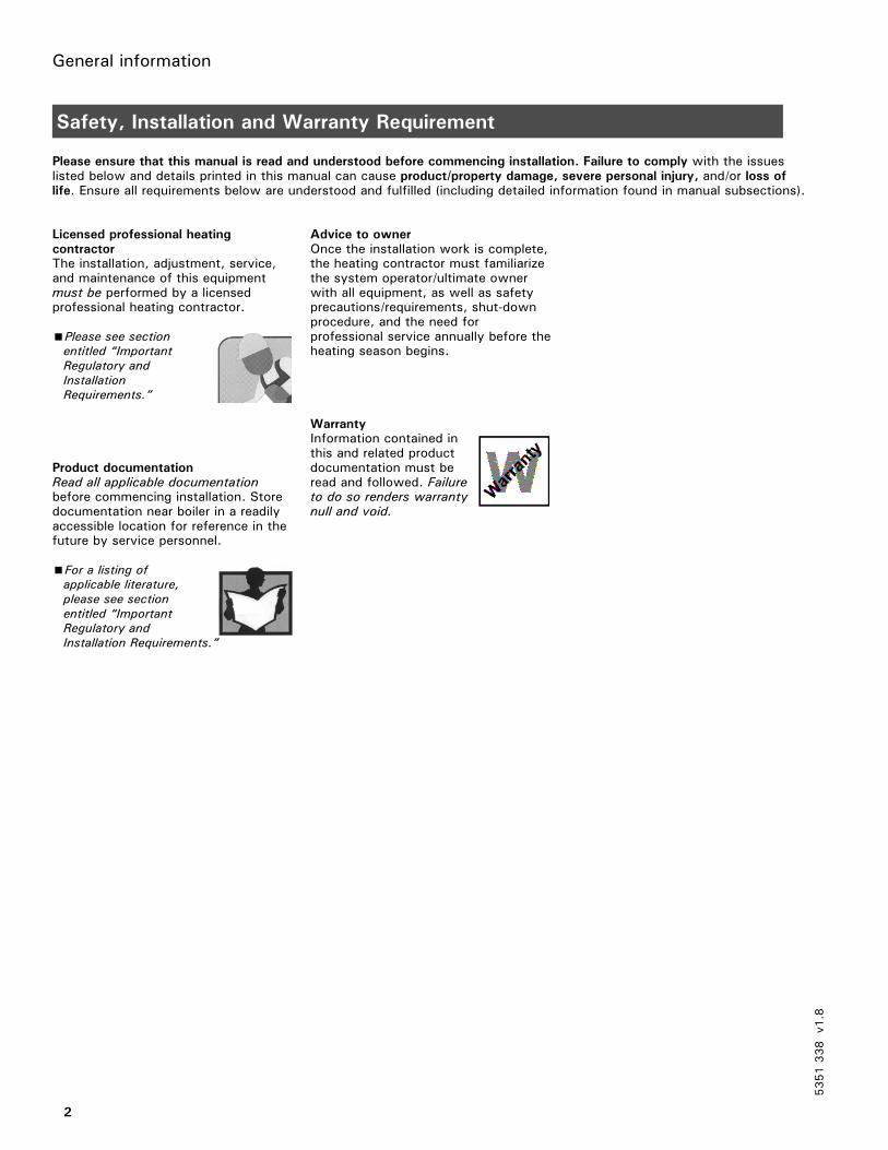
Circuit Diagram 7
Multi-boiler system with return valve for return temperature protection
in conjunction with Vitorond 200, VD2
A Boiler with Vitotronic 100, GC1B Domestic hot water tankC Heating circuit with mixing valve
Plugs
§ Boiler temperature sensoraJ A Temperature sensor T1sL Boiler circuit pumpfÖ Power supply connection,
120 VACfA Burner (1st stage)gS A1 Return valve
lÖ Burner (2nd stage/modulating)aVD Connection of external
equipment (see page 60)aVH Connection of external
equipment (see page 60)
5351338
v1.8
B
317A
A A
317A
T1
CC
9041
40
146
143
52A1
29
T1
9041
40
146
143
52A1
29

Heating system types
20
Circuit Diagram 7 (continued)
Possible applications
E.g. old systems or systems in marketgardens and/or systems in which thereis no facility for making modificationsor adjustments to the heating circuitsconnected downstream.The cascade and DHW tank controlmust be activated by a buildingautomation system.
This circuit diagram represents a
recommendation only. It is the
responsibility of the customer and/or
heating contractor to check that this
recommendation is complete and fully
functional. Three-phase equipment
must be connected via additional
power contactors.
When the return temperature fallsbelow the required minimum value,the 3-port mixing valve on the boilersis proportionally closed via thetemperature sensor T1, therebyassuring protection of the boiler.
The boiler and the heating circuitsdownstream are hydraulicallydecoupled. The supply temperatureis controlled via the commontemperature sensor.
Available system accessories
Flue gas temperature sensor
Coding of
system type
Change required Automatic change
01: 1 Set coding ”01: 3” for multi-boiler systemwith external cascade control via switchcontacts
–––
02: 1 Set coding ”02: 2” for operation withmodulating burner
–––
03: 0 Set coding ”03: 1” for oil-fired operation(re-setting is not possible)
–––
0C: 4 Set coding ”0C: 1” for continuous returntemperature control
–––
4A: 0 ––– Connection of the temperature sensor T1 atplug aJA;Coding is automatically changed to ”4A: 1”
4d: 1 Set coding ”4d: 2” for boiler circuit pumpat plug sL
–––
5351338
v1.8
IMPORTANT

Heating system types
21
Circuit Diagram 8
Multi-boiler system with low-loss header and return valve for elevating the return temperature
in conjunction with Vitorond 200, VD2
A Boiler with Vitotronic 100, GC1B Domestic hot water tankC Heating circuit with mixing valveD Low-loss header
Plugs
§ Boiler temperature sensoraJ A Temperature sensor T1sL Boiler circuit pumpfÖ Power supply connection,
120 VACfA Burner (1st stage)gS A1 Return valve
lÖ Burner (2nd stage/modulating)aVD Connection of external
equipment (see page 60)aVH Connection of external
equipment (see page 60)
5351338
v1.8
B
317A
A A
317A
T1
CC
9041
40
146
143
52A1
29
T1
9041
40
146
143
52A1
29
D

Heating system types
22
Circuit Diagram 8 (continued)
Possible applications
E.g. old systems or systems in marketgardens as well as systems in whichthere is a lack of clarity in the hydraulicinstallation and/or systems where thereis no facility for making modificationsor adjustments to the heating circuitsconnected downstream.The cascade and DHW tank controlmust be activated by a buildingautomation system.
This circuit diagram represents a
recommendation only. It is the
responsibility of the customer and/or
heating contractor to check that this
recommendation is complete and fully
functional. Three-phase equipment
must be connected via additional
power contactors.
When the return temperature fallsbelow the required minimum value,the return valve on the boilers isproportionally closed via thetemperature sensor T1, therebyassuring protection of the boiler.
The supply temperature is controlledby the temperature sensor in thelow-loss header.
Available system accessories
Flue gas temperature sensor
Coding of
system type
Change required Automatic change
01: 1 Set coding ”01: 3” for multi-boiler systemwith external cascade control via switchcontacts
–––
02: 1 Set coding ”02: 2” for operation withmodulating burner
–––
03: 0 Set coding ”03: 1” for oil-fired operation(re-setting is not possible)
–––
0C: 4 Set coding ”0C: 1” for continuous returntemperature control
–––
4A: 0 ––– Connection of the temperature sensor T1 atplug aJA;Coding is automatically changed to ”4A: 1”
4d: 1 Set coding ”4d: 2” for boiler circuit pumpat plug sL
–––
5351338
v1.8
IMPORTANT The boiler circuit pumps on each
boiler must be sized so that their
supply is at least equal to the
maximum possible total heating
circuit supply.
Recommendation: 110%.
CAUTION

Heating system types
23
Circuit Diagram 9
Several heating circuits and one mixing valve heating circuit
Single-boiler system with Vitocrossal 300
A Boiler with Vitotronic 100, GC1B Domestic hot water tankC Heating circuit with mixing valveD Neutralizing unit
Plugs
§ Boiler temperature sensor% DHW tank temperature sensor
(accessory)sA DHW pumpfÖ Power supply connection,
120 VAC
fA Burner (1st stage)lÖ Burner (2nd stage/modulating)aVD Connection of external
equipment (see page 60)aVH Connection of external
equipment (see page 60)
5351338
v1.8
3521
B
C C
A
9041
40
146
143
D

Heating system types
24
Circuit Diagram 9 (continued)
This circuit diagram represents a
recommendation only. It is the
responsibility of the customer and/or
heating contractor to check that this
recommendation is complete and fully
functional. Three-phase equipment
must be connected via additional
power contactors.
The Vitocrossal 300 is operated withconstant boiler water temperature bymeans of the boiler control unit.Two-stage or modulating burnerscan be controlled.
The boiler water temperature which isestablished in the heating mode ishigher than the maximum heatingsystem supply temperature by anadjustable difference.
Available system accessories
Flue gas temperature sensor
Coding of
system type
Change required Automatic change
00: 1 ––– With DHW tank:Coding is automatically changed to ”00: 2”
02: 1 Set coding ”02: 2” for operation withmodulating burner
–––
0C: 4 Set coding ”0C: 0” –––
0d: 2 Set coding ”0d: 0” –––
5351338
v1.8
IMPORTANT

Heating system types
25
Circuit Diagram 10
Single-boiler system with several heating circuits and one mixing valve heating circuit
in conjunction with Vitocrossal 300
A Boiler with Vitotronic 100, GC1B Domestic hot water tankC Heating circuit with mixing valveDMixing valve heating circuit
orE Underfloor heating circuit with
mixing valveF Limit thermostat (max. limit)G Neutralizing unit
Plugs
§ Boiler temperature sensor% DHW tank temperature sensor
(accessory)sÖ A1 Close mixing valves with
external heating circuit controlssA DHW pump
fÖ Power supply connection,120 VAC
fA Burner (1st stage)lÖ Burner (2nd stage/modulating)aVD Connection of external
equipment (see page 60)aVH Connection of external
equipment (see page 60)
5351338
v1.8
3
B
C D
A
9041
40
146
143
G
or
E
F
521
A1
20

Heating system types
26
Circuit Diagram 10 (continued)
Possible applications
For heating circuits with differenttemperatures.
This circuit diagram represents a
recommendation only. It is the
responsibility of the customer and/or
heating contractor to check that this
recommendation is complete and fully
functional. Three-phase equipment
must be connected via additional
power contactors.
The Vitocrossal 300 is operated withconstant boiler water temperature bymeans of the boiler control unit.Two-stage or modulating burners canbe controlled.
The Vitocrossal 300 has two returnconnections. The heating circuits withthe higher return temperature areconnected to the return connection atthe top, those with the lowertemperatures to the return connectionat the bottom.
Please note:
At least 15% of the take-off from therated output must be connected to thereturn connection at the bottom.
The boiler water temperature which isestablished in the heating mode ishigher than the maximum heatingcircuit supply temperature by anadjustable difference.
Available system accessories
Flue gas temperature sensor
Coding of
system type
Change required Automatic change
00: 1 ––– With DHW tank:Coding is automatically changed to ”00: 2”
02: 1 Set coding ”02: 2” for operation withmodulating burner
–––
0C: 4 Set coding ”0C: 0” –––
0d: 2 Set coding ”0d: 0” –––
5351338
v1.8
IMPORTANT

Heating system types
27
Circuit Diagram 11
Multi-boiler system with several heating circuits and one mixing valve heating circuit
in conjunction with Vitocrossal 300
A Boiler with Vitotronic 100, GC1B Domestic hot water tankC Heating circuit with mixing valveD Neutralizing unit
Plugs
§ Boiler temperature sensorfÖ Power supply connection,
120 VACfA Burner (1st stage)gS A1 Motorized isolation valvelÖ Burner (2nd stage/modulating)
aVD Connection of externalequipment (see page 60)
aVH Connection of externalequipment (see page 60)
5351338
v1.8
B
C
A
C
AD D
3
9041
40
146
143
52A1
39041
40
146
143
52A1

Heating system types
28
Circuit Diagram 11 (continued)
Possible applications
The cascade and DHW tank controlmust be activated by a buildingautomation system.
This circuit diagram represents a
recommendation only. It is the
responsibility of the customer and/or
heating contractor to check that this
recommendation is complete and fully
functional. Three-phase equipment
must be connected via additional
power contactors.
The Vitocrossal 300 is operated withconstant boiler water temperature bymeans of the boiler control unit.Two-stage or modulating burners canbe controlled.
The Vitocrossal 300 has two returnconnections. The heating circuitswith the higher return temperatureare connected to the returnconnection at the top, those withthe lower temperatures to the returnconnection at the bottom.
Please note:
At least 15% of thetake-off from the rated output mustbe connected to the return connectionat the bottom.
The boiler water temperature whichis established in the heating mode ishigher than the maximum heatingcircuit supply temperature by anadjustable difference.
Motorized isolation valve
Connect motorized isolation valveadaptor (Part No. 7134 560) or 24Vvalve adaptor (Part No. 7134 559),installed in connection enclosure, inparallel.Use electric junction box if necessary.
Available system accessories
Flue gas temperature sensor
Coding of
system type
Change required Automatic change
01: 1 Set coding ”01: 3” for multi-boiler systemwith external cascade control via switchcontacts
–––
02: 1 Set coding ”02: 2” for operation withmodulating burner
–––
0d: 2 Set coding ”0d: 0” –––5351338
v1.8
IMPORTANT

Heating system types
29
Circuit Diagram 12
Multi-boiler system with several heating circuits, one mixing valve heating circuit and Vitorond with shunt pump
in conjunction with Vitocrossal 300 and Vitorond 200
A Boiler with Vitotronic 100, GC1B Domestic hot water tankC Heating circuit with mixing valveD Neutralizing unit
Plugs
§ Boiler temperature sensoraJ A Temperature sensor T1aJ B Temperature sensor T2sL Shunt pumpfÖ Power supply connection,
120 VACfA Burner (1st stage)
gS A1 Motorized isolation valvelÖ Burner (2nd stage/modulating)aVD Connection of external
equipment (see page 60)aVH Connection of external
equipment (see page 60)
5351338
v1.8
B AAD
3
9041
40
146
143
39041
40
146
143
52A1
17A
T1
T217B29
CC

Heating system types
30
Circuit Diagram 12 (continued)
Possible applications
The cascade and DHW tank controlmust be activated by a buildingautomation system.
This circuit diagram represents a
recommendation only. It is the
responsibility of the customer and/or
heating contractor to check that this
recommendation is complete and fully
functional. Three-phase equipment
must be connected via additional
power contactors.
The Vitocrossal 300 (lead boiler) andthe Vitorond lag boilers are operatedwith modulating boiler watertemperature and load-dependentsequential control by means of theoutdoor-reset logic control system.Two-stage or modulating burners canbe controlled.Through the control system which islinked via the LON BUS, the boilersupply temperature which isestablished is higher than themaximum heating circuit supplytemperature by an adjustabledifference. The heating system canbe operated in accordance with aseparate heating curve.
The Vitocrossal 300 boilers havetwo return connections. The heatingcircuits with the higher returntemperature are connected to thereturn connection at the top, thosewith the lower temperatures to thereturn connection at the bottom.
Please note:
At least 15% of thetake-off from the rated output mustbe connected to the returnconnection at the bottom.
The return temperature raisingfunctionality of the Vitorondmodulating boiler is available as anaccessory or must be provided onsite.The return temperature is raised bymeans of the shunt pump and byclosing the isolation valve.The temperature sensor T1 activatesthe isolation valve. The temperaturesensor T2 switches the shunt pump.
Available system accessories
Flue gas temperature sensor
Coding ofsystem type
Change required Automatic change
01: 1 Set coding ”01: 3” for multi-boiler systemwith external cascade control via switchcontacts
–––
02: 1 Set coding ”02: 2” for operation withmodulating burner
–––
0C: 4 Only with Vitotronic 100 for the Vitocrossal300:Set coding ”0C: 0”
–––
0d: 2 Set coding ”0d: 0” –––
4A: 0 ––– Only with Vitotronic 100 for the Vitorond:Connection of the temperature sensor T1 atplug aJA;Coding is automatically changed to ”4A: 1”
4b: 0 ––– Only with Vitotronic 100 for the Vitorond:Connection of the temperature sensor T2 atplug aJB;Coding is automatically changed to ”4b: 1”
5351338
v1.8
IMPORTANT
Heating system types
31
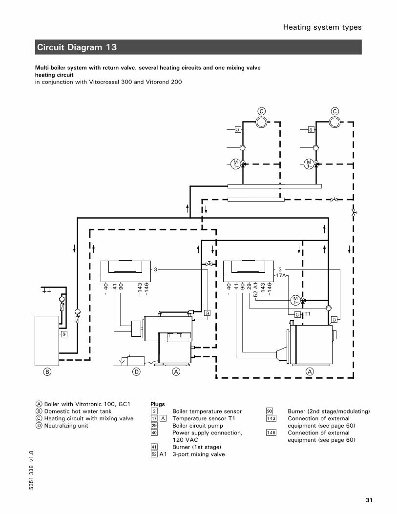
Circuit Diagram 13
Multi-boiler system with return valve, several heating circuits and one mixing valve
heating circuit
in conjunction with Vitocrossal 300 and Vitorond 200
A Boiler with Vitotronic 100, GC1B Domestic hot water tankC Heating circuit with mixing valveD Neutralizing unit
Plugs
§ Boiler temperature sensoraJ A Temperature sensor T1sL Boiler circuit pumpfÖ Power supply connection,
120 VACfA Burner (1st stage)gS A1 3-port mixing valve
lÖ Burner (2nd stage/modulating)aVD Connection of external
equipment (see page 60)aVH Connection of external
equipment (see page 60)
5351338
v1.8
B AAD
3
9041
40
146
143
3
9041
40
146
143
17A
29
52A1
T1
CC
Heating system types
32
Circuit Diagram 13 (continued)
Possible applications
For heating circuits with temperaturedifferences ≥20 K.The cascade and DHW tank controlmust be activated by a buildingautomation system.
This circuit diagram represents a
recommendation only. It is the
responsibility of the customer and/or
heating contractor to check that this
recommendation is complete and fully
functional. Three-phase equipment
must be connected via additional
power contactors.
The Vitocrossal 300 (lead boiler) andthe Vitorond lag boilers are operatedwith modulating boiler watertemperature and load-dependentsequential control by means of theoutdoor-reset logic control system.Two-stage or modulating burnerscan be controlled.Through the control system which islinked via the LON BUS, the boilersupply temperature which isestablished is higher than themaximum heating circuit supplytemperature by an adjustabledifference. The heating system canbe operated in accordance with aseparate heating curve.
The Vitocrossal 300 boilers havetwo return connections. The heatingcircuits with the higher returntemperature are connected to thereturn connection at the top, thosewith the lower temperatures to thereturn connection at the bottom.
Please note:
At least 15 % of thetake-off from the rated output mustbe connected to the return connectionat the bottom.
The T1 temperature sensor measuresthe return temperature.The return valve is activated via theboiler control unit so as to ensure thatthe return temperature does not fallbelow the minimum value.
Available system accessories
Flue gas temperature sensor
Coding of
system type
Change required Automatic change
01: 1 Set coding ”01: 3” for multi-boiler systemwith external cascade control via switchcontacts
–––
02: 1 Set coding ”02: 2” for operation withmodulating burner
–––
0C: 4 Only with Vitotronic 100 for the Vitocrossal300:Set coding ”0C: 0”Only with Vitotronic 100 for the Vitorond300: Set coding ”0C: 1” for continuousreturn temperature control
–––
0d: 2 Only with Vitotronic 100 for the Vitocrossal300:Set coding ”0d: 0”
–––
4A: 0 ––– Only with Vitotronic 100 for the Vitorond:Connection of the Therm-Control temperaturesensor at plug aJA;Coding is automatically changed to ”4A: 1”
4d: 1 Only with Vitotronic 100 for the Vitocrossal300:Set coding ”4d: 2” for boiler circuit pump atplug sL
5351338
v1.8
IMPORTANT

Heating system types
33
Circuit Diagram 14 (CM2 only)
Single-boiler system with several heating circuits and one mixing valve heating circuit
in conjunction with Vitocrossal 200
A Boiler with Vitotronic 100, GC1B Domestic hot water tankC Heating circuit with mixing valveDMixing valve heating circuit
orE Underfloor heating circuit with
mixing valveF Limit thermostat (max. limit)G Neutralizing unit
Plugs
§ Boiler temperature sensor% DHW tank temperature sensor
(accessory)sÖ A1 Close mixing valves with
external heating circuit controlssA DHW pump
fÖ Power supply connection,120 VAC
fA BurnerlÖ Burner modulationaVD Connection of external
equipment (see page 60)aVH Connection of external
equipment (see page 60)
5351338
v1.8
Heating system types
34
Circuit Diagram 14 (CM2 only) (continued)
Possible applications
For heating circuits with differenttemperatures.
This circuit diagram represents a
recommendation only. It is the
responsibility of the customer and/or
heating contractor to check that this
recommendation is complete and fully
functional.
The Vitocrossal 200 is operated withconstant boiler water temperature bymeans of the boiler control unit and theViessmann fully modulating burner.
Coding of
system type
Change required Automatic change
00: 1 ––– With DHW tank:Coding is automatically changed to ”00: 2”
02: 1 Set coding ”02: 2” for operation withmodulating burner
–––
0C: 4 Set coding ”0C: 0” –––
0d: 2 Set coding ”0d: 0” –––
5351338
v1.8
IMPORTANT

Heating system types
35
Circuit Diagram 15 (CM2 only)
Multi-boiler system with several heating circuits and one mixing valve heating circuit
in conjunction with Vitocrossal 200
A Boiler with Vitotronic 100, GC1B Domestic hot water tankC Heating circuit with mixing valveD Neutralizing unit
Plugs
§ Boiler temperature sensorfÖ Power supply connection,
120 VACfA BurnergS A1 Motorized isolation valvelÖ Burner modulation
aVD Connection of externalequipment (see page 60)
aVH Connection of externalequipment (see page 60)
5351338
v1.8

Heating system types
36
Circuit Diagram 15 (CM2 only) (continued)
Possible applications
The cascade and DHW tank controlmust be activated by a buildingautomation system.
This circuit diagram represents a
recommendation only. It is the
responsibility of the customer and/or
heating contractor to check that this
recommendation is complete and fully
functional.
The Vitocrossal 200 is operated withconstant boiler water temperature bymeans of the boiler control unit andthe Viessmann fully modulating burner.
Motorized isolation valve
Connect motorized 120V isolationvalve adaptor (Part No. 7511 367)or 24V valve adaptor (Part No.7511 366), installed in connectionenclosure, in parallel.Use electric junction box if necessary.
Coding of
system type
Change required Automatic change
01: 1 Set coding ”01: 3” for multi-boiler systemwith external cascade control via switchcontacts
–––
02: 1 Set coding ”02: 2” for operation withmodulating burner
–––
0d: 2 Set coding ”0d: 0” –––
5351338
v1.8
IMPORTANT

Installation
37
Mounting the Front Part of the Control Unit (VD2/VD2A/CT3 only)
1. Position the front part of the housingand clip hinges to counter-parts onmain housing.
2. Release the stay bar, open it upand lock in position at point A.
3. Insert the flat cable from theOptolink into plug ”X20”.
4. Insert the plug of the programmingunit into socket ”X10”. Use cableguides in cover for routing.
5. Engage the stay bar in the fronthousing.
6.Close the front of the housing.
7. Secure front housing with suppliedscrews.
8. Install cover of the connectionenclosure and support with suppliedscrew.
5351338
v1.8
1.
2.
3.
4.5.
6.
7.
8.
A

Installation
38
Opening the Control Unit (VD2/VD2A/CT3 only)
1. Remove the cover of theconnection enclosure.
2.Unscrew the screws from thefront housing.
3. Swing up the front part of thecontrol housing.
4. Position the stay bar so that itsupports the front housing.
5351338
v1.8
4.
3.
1.
2.

Installation
39
Control and Junction Box Installation Instructions (for CM2 only)
1. Route cables and capillaries fromcontrol through the opening in thecontrol panel. Guide the cables tothe junction box through theopening in the rear panel and alongthe top rail to the control. Secureall cables to the rail with cable ties.Insert capillaries into the sensor well.Note: Never allow cables to come
in contact with hot metalcomponents.
2. Mount the control to the controlpanel.
3. Secure the control to the controlpanel with screws.Note: Screws to secure control are
included with the cosmeticcover in the boiler jacketingpackage.
4. Install the junction box to the rearpanel either right or left. Secure thejunction box with 4 x 4.8 metalscrews.Note:The ground screw and ground
wire can be removed and thenreinstalled with the boiler backpanel attached.
5351338
v1.8
Do not bend or kink the capillaries.Damaging the capillaries leads tomalfunction.
WARNING

Installation
40
Mounting the Front Part of the Control Unit (CM2 only)
1. Position the front part of the housingand clip hinges to counter-parts onmain housing.
2. Release the stay bar, open it upand lock in position at point A.
3. Insert the flat cable from theOptolink into plug ”X20”.
4. Insert the plug of the programmingunit into socket ”X10”. Use cableguides in cover for routing.
5. Engage the stay bar in the fronthousing.
6.Close the front of the housing.
7. Secure front housing with suppliedscrews.
8. Install control cosmetic cover.
5351338
v1.8
A

Installation
41
Opening the Control Unit (CM2 only)
1. Remove the control cosmeticcover .
2.Unscrew the screws from thefront housing.
3. Swing up the front part of thecontrol housing.
4. Position the stay bar so that itsupports the front housing.
5351338
v1.8

Installation
42
Overview of Electrical Connections
Low voltage connections (motherboard)
§ Boiler temperature sensor (KTS)% DHW tank temperature sensoraG Flue gas temperature sensoraJA Return temperature sensor T1aJB Return temperature sensor T2aVD Connection of external
equipmentaVG KM BUS participantaVH Connection of external
equipment
Line voltage connections (motherboard)
sÖ A1Control outputsA DHW pumpsL Shunt pump or
boiler circuit pumpfÖ Power supply connectionfA Burner (1st stage)gÖ Compiled failure alarmgS A1Return valve
orIsolation/modulating valve
lÖ Burner (2nd stage/modulating)aBÖ Connection of external
equipment, e.g. additionalsafety equipment
aBA Safety circuit, potential freeaBH Power supply connection for
accessories
5351338
v1.8
145
17
17
5
3/2
15
143
146
B
A
90
41
151
150
A1/M1
A1/M1
21
52
20
29
50
40
156
156

Installation
43
Overview of Electrical Connections (VD2/VD2A/CT3 only) (continued)
5351338
v1.8
[29]
[20] A1

Installation
44
Overview of Electrical Connections (CM2 only) (continued)
5351338
v1.8
Installation
45
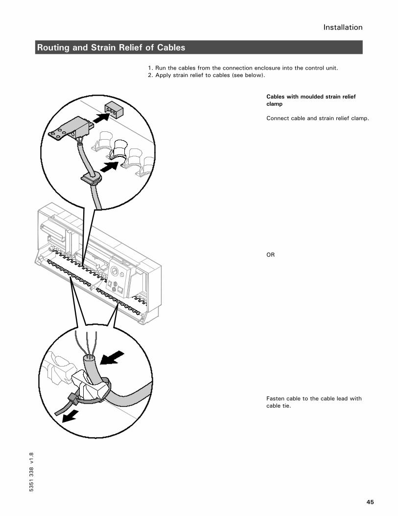
Routing and Strain Relief of Cables
1. Run the cables from the connection enclosure into the control unit.2. Apply strain relief to cables (see below).
Cables with moulded strain relief
clamp
Connect cable and strain relief clamp.
OR
Fasten cable to the cable lead withcable tie.
5351338
v1.8

Installation
46
Inserting the Boiler Coding Card
Only use the boiler coding card included with the boiler.
Boiler Coding card Part no.
Vitocrossal 300, type CT3 1040 7820 144
Vitorond 200, VD2 / VD2A 1020 7820 142
Vitocrossal 200, CM2 1041 7820 145
1. Push the boiler coding card throughthe recess in the cover and insertit in plug-in location ”X7”.
5351338
v1.8
For matching the operation of the
control unit to the boiler, the boiler
coding card which is supplied as part
of the standard delivery of the boiler
may be used.
CAUTION

Installation
47
Setting of the Fixed High Limit (if required)
Settings on the control unit
The setting for the fixed high limit andthe other settings are dependent on thesafety equipment installed inaccordance with applicable codes.
The fixed high limit is supplied with
a factory setting of 110°C / 230°F.
- On Vitotronic 100, GC1 for
Vitorond 200, VD2 of
110°C / 230°F
- Adjustment to 99°C / 210°F
- On Vitotronic 100, GC1 for
Vitocrossal 300, CT3
Vitocrossal 200, CM2
of 99°C / 210°F
No adjustment
¨ Disconnect power to control and
burner!
1.Unclip the fuse box and swingupwards.
2. Turn the slotted screw on the rearof the fixed high limit until the slotpoints to 99°C / 210°F (onceadjusted, the fixed high limit cannotbe reset to 110°C / 230°F).
3. Re-fit the fuse box.
Non-condensing boiler(VD2/VD2A) °C / °F
Condensing boiler(CT3) °C / °F
Condensing boiler(CM2) °C / °F
Fixed high limit 110 / 230 99 / 210 99 / 210 99 / 210
Adjustable high limit 100 / 212 95 / 203 95 / 203 95 / 203
Coding for the electronic maximumtemperature limiter of Vitotronic 100;set code 06 to the temperature asshown or less
93 / 200 87 / 188 87 / 188 88 / 190
5351338
v1.8
3.
1.
2.
A

Installation
48
Setting of the Adjustable High Limit (if required)
The adjustable high limit is supplied
with a factory setting of 95°C / 203°F
Adjustment to 100°C / 212°F
1. Disconnect power to control andburner.
2.Using a suitable screwdriver,lever out and remove the selectorknob ”R” behind the hinged cover.
3.Using a pair of pointed pliers, breakoff the cams identified by theshaded areas in the Fig. from thestop dial.
A 75 to 1100°C167 to 212°F
4. Fit the selector knob ”R” so thatthe marking is in the centre of theselected range.
Note the setting of coding address
”06”!
5351338
v1.8
1.
2.
A
3.
IMPORTANT
If the system is operated in
conjunction with a domestic hot
water tank, ensure that the
maximum permissible domestic
hot water temperature is not
exceeded. If necessary, install a
suitable safety device for this
purpose.
WARNING

Installation
49
Sensor Connection
ATemperature sensor T2BTemperature sensor T1CBoiler temperature sensorDFlue gas temperature sensor
5351338
v1.8
17B 17A 3 15
1 2 3 1 2 3 1 2 3 1 2 3
DA B C

Installation
50
Connection of the Boiler Temperature Sensor
Electrical connection
See page 42.
The sensor measures the boiler
water temperature of the boiler.
The boiler temperature sensor isinstalled at the same time as theboiler insulation.
Check the sensor
1.Disconnect plug§ in theterminal compartment.
2.Measure resistance of sensor atterminals ”1” and ”2” of the plugor ”2” and ”3” (if a second DHWtank temperature sensor isconnected).
Boiler water
temperature
in °C / °F
Resistance
in ΩΩΩΩ
40 / 10450 / 12260 / 140
578597616
3.Compare the value measured withthe current temperature. If thevalue differs significantly, checkinstallation and, if necessary,replace sensor.
Technical data
Degree of protection: IP 32Ambient temperatureduring operation:
0 to + 130°C32 to + 266°F
during storage and transport:-20 to + 170°C- 4 to + 158°F
Electrical connection
The sensors are ready to plug in.Insert the boiler temperature sensorin socket ”3” of the boiler control.
5351338
v1.8
3
Resistance
in
4000
540
560
580
600
620
640
660
680
700
720
740
760
20 40 60 80 100 120 140
Boiler temperature in °C / °F32 68 141 176 212 248 284104
Installation
51
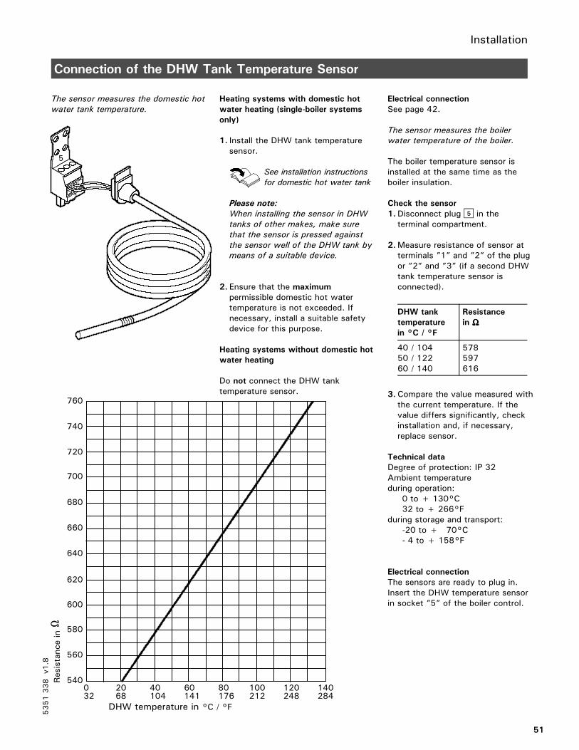
Connection of the DHW Tank Temperature Sensor
The sensor measures the domestic hot
water tank temperature.
Heating systems with domestic hot
water heating (single-boiler systems
only)
1. Install the DHW tank temperaturesensor.
See installation instructions
for domestic hot water tank
Please note:
When installing the sensor in DHW
tanks of other makes, make sure
that the sensor is pressed against
the sensor well of the DHW tank by
means of a suitable device.
2. Ensure that the maximumpermissible domestic hot watertemperature is not exceeded. Ifnecessary, install a suitable safetydevice for this purpose.
Heating systems without domestic hot
water heating
Do not connect the DHW tanktemperature sensor.
Electrical connection
See page 42.
The sensor measures the boiler
water temperature of the boiler.
The boiler temperature sensor isinstalled at the same time as theboiler insulation.
Check the sensor
1.Disconnect plug% in theterminal compartment.
2.Measure resistance of sensor atterminals ”1” and ”2” of the plugor ”2” and ”3” (if a second DHWtank temperature sensor isconnected).
DHW tank
temperature
in °C / °F
Resistance
in ΩΩΩΩ
40 / 10450 / 12260 / 140
578597616
3.Compare the value measured withthe current temperature. If thevalue differs significantly, checkinstallation and, if necessary,replace sensor.
Technical data
Degree of protection: IP 32Ambient temperatureduring operation:
0 to + 130°C32 to + 266°F
during storage and transport:-20 to + 170°C- 4 to + 158°F
Electrical connection
The sensors are ready to plug in.Insert the DHW temperature sensorin socket ”5” of the boiler control.
5351338
v1.8
5
Resistance
in
4000
540
560
580
600
620
640
660
680
700
720
740
760
20 40 60 80 100 120 140
DHW temperature in °C / °F32 68 141 176 212 248 284104

Installation
52
Connection of the Return Temperature Sensor
Strap-on temperature sensor and immersion temperature sensor
For measuring the boiler return
and return temperature.
Electrical connection
The sensor is inserted in socket”17A” or ”17B” on the boilercontrol.
Check the sensor
1.Disconnect plug aJA or aJBin the terminal compartment ofthe boiler control.
2.Measure resistance of sensor atterminals ”1” and ”2” of the plug.
Return
temperature
in °C / °F
Resistance
in ΩΩΩΩ
30 / 8640 / 10460 / 140
569592643
3.Compare the value measured withthe current temperature. If thevalue differs significantly, checkinstallation and, if necessary,replace sensor.
Technical data
Degree of protection: IP 32Ambient temperatureduring operation: 0 to + 100°C
32 to + 212°Fduring storage and transport:
-20 to + 70°C-4 to + 158°F
5351338
v1.8
17A or 17B
17A or 17B
30 40 50 60 7070 80 90540
560
580
600
620
640
660
680
700
720
740
20 100
Resistance
in
68 86 104 122 140 158 176 194 212
Return temperature in °C / °F

Installation
53
Connection of the Flue Gas Temperature Sensor (VD2/VD2A/CT3 only)
The sensor measures the flue gas
temperature and monitors the
selected limit value.
Electrical connection
The sensor is inserted in socket”15” on the control unit.
Check flue gas temperature sensor
1.Disconnect plug aG in theterminal compartment.
2.Measure resistance of sensor atterminals ”1” and ”2” of theplug.
Flue gas
temperature
in °C / °F
Resistance
in ΩΩΩΩ
180 / 176160 / 320200 / 392
650800880
3.Compare the value measuredwith the current temperature.If the value differs significantly,check installation and, ifnecessary, replace sensor.
Technical data
Degree of protection: IP 60Ambienttemperatureduring operation:
0 to + 600°C32 to + 1112°F
during storage and transport:–20 to + 670°C- 4 to + 158°F
5351338
v1.8
0500
40 80 120 160 200 240 280
540
580
620
660
700
740
780
820
860
900
940
980
1020
Resistance
inΩΩ ΩΩ
Flue gas temperature in °C / °F
32 104 176 248 360 392 464 536

Installation
54
Connection of the Pumps (VD2/VD2A/CT3 only)
Available pump connections
20A1/M1
29
sÖ A1/M1Heating circuit hightemperature (without mixing valve)Terminals 5 - L, - G , - N
sA Circulation pump for heatingup the domestic hot water tank -Terminals 4 - L, - G , - N
sL Shunt pump, boiler circuit pumpTerminals 6 - L, - G, - N.
Install pumps: see
manufacturer’s
instructions.
120 VAC pumps
Note:
The maximum power consumption of
all pumps is 4A .
Rated current: max. 2 FLA
Recommended connection
cable: AWG 14
Use contactor for pumps with higher
current rating
Connect the 3-wire cable from thepump to the corresponding terminals.
240 VAC or 3 PH pumps
Please note:
Use contactor and/or motor starter to
power pump.
For activating the contactor:
Rated current: max. 2 FLA
Recommended connection
wire size: AWG 14
Please ensure that all connections and
wire sizes comply with local and
national codes.
1.Select the contactor and theconnecting wire in accordance withthe rating of the pump that is to beconnected.
2.Connect pump and power supply tothe contactor.
3.Connect contactor coil to thecorresponding terminals.
5351338
v1.8
Installation
55
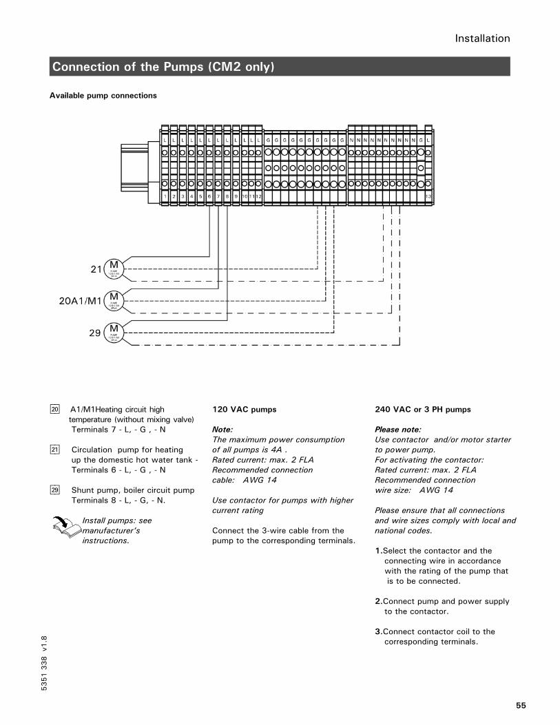
Connection of the Pumps (CM2 only)
Available pump connections
sÖ A1/M1Heating circuit hightemperature (without mixing valve)Terminals 7 - L, - G , - N
sA Circulation pump for heatingup the domestic hot water tank -Terminals 6 - L, - G , - N
sL Shunt pump, boiler circuit pumpTerminals 8 - L, - G, - N.
Install pumps: see
manufacturer’s
instructions.
120 VAC pumps
Note:
The maximum power consumption
of all pumps is 4A .
Rated current: max. 2 FLA
Recommended connection
cable: AWG 14
Use contactor for pumps with higher
current rating
Connect the 3-wire cable from thepump to the corresponding terminals.
240 VAC or 3 PH pumps
Please note:
Use contactor and/or motor starter
to power pump.
For activating the contactor:
Rated current: max. 2 FLA
Recommended connection
wire size: AWG 14
Please ensure that all connections
and wire sizes comply with local and
national codes.
1.Select the contactor and theconnecting wire in accordancewith the rating of the pump thatis to be connected.
2.Connect pump and power supplyto the contactor.
3.Connect contactor coil to thecorresponding terminals.
5351338
v1.8

Installation
56
Connection of Boiler Return Mixing Valve or Isolation/Modulating Valve
actuator(VD2/VD2A/CT3 only)
1 120V or 24V Valve Adaptor
2 DIN rail in connection enclosure
3 aBH Terminals
120V Valve Adaptor
Rated voltage: 120 VACRated current: max. 0.1 FLARecommended connectionwire size: AWG 14Part No. 7134 560
24V Valve Adaptor
Rated voltage: 24 VACRated current: max. 0.15 FLARecommended connectionwire size: AWG 14Part No. 7134 559
Operating time:
5 to 199 sec. selected via codingaddress “40”.
1 120V Valve Adaptor
2 120V valve actuator
1 24V Valve Adaptor
2 24V valve actuator
1. Disconnect power to control.
2. Install 120V or 24V ValveAdaptor on DIN rail insideconnection enclosure.
3. Insert the plug gS into socketgS on the control.
4. Fasten cable with tie(see page.45).
5. Connect black wire of theadaptor to connection aBH onthe DIN rail- Terminal 8,9 or 10.
6. Connect valve actuator wiresto the adaptor terminals asshown on figures.
5351338
v1.8

Installation
57
Connection of Boiler Return Mixing Valve or Isolation/Modulating Valve
actuator(CM2 only)
1 120V or 24V Valve Adaptor
2 DIN rail in connection enclosure
3 120V L out power supply
120V Valve Adaptor
Rated voltage: 120 VACRated current: max. 0.1 FLARecommended connectionwire size: AWG 14Part No. 7511367
24V Valve Adaptor
Rated voltage: 24 VACRated current: max. 0.15 FLARecommended connectionwire size: AWG 14Part No. 7511366
Operating time:
5 to 199 sec. selected via codingaddress “40”.
1 120V Valve Adaptor
2 120V valve actuator
1 24V Valve Adaptor
2 24V valve actuator
1. Disconnect power to control.
2. Install 120V or 24V ValveAdaptor on DIN rail insideconnection enclosure.
3. Insert the plug gS into socketgS on the control.
4. Fasten cable with tie(see page.45).
5. Connect black wire of theadaptor to connection 120V Lout the DIN rail- Terminals 10,11 or 12.
6. Connect valve actuator wiresto the adaptor terminals asshown on figures.
5351338
v1.8
10 11 12

Installation
58
Making Space for Accessory Adaptors on the DIN Rail (CM2 only)
1. Push up on the bottom front ofthe DIN rail clamp to remove andset aside.
2.Using a flat head screwdriver,remove the 4 ’spare’ DINterminals 23, 24, 25 and 26 oneat a time. Place the screwdriverbetween the rail and the base ofthe terminal and turn thescrewdriver clockwise . Discardthe removed terminals.
3. Re-install the DIN rail clamp byhooking the latch of the clamparound the top of the rail and thenpush down on the front of theclamp.
Note: See separate InstallationInstructions for accessoryadaptors.
5351338
v1.8

Installation
59
Vitotronic 100, GC1 with 30% LTP Package (VD2/VD2A only)
5351338
v1.8 VD2/VD2A
1 - 17B Sensor (strap-on)
5
2

Installation
60
Connection of External Controls
Operation with two-stage burner
ASwitch on 1st stage burner
Connect dry contact at terminals ”1”and ”2” of the plug aVD .
Contact closed:The 1st stage burner is switched on.The 2nd stage burner is only switchedon to maintain the minimumtemperature (not with Vitocrossal300). The boiler water temperature islimited by the electronic maximumtemperature limit (coding address ”06”)if this is set below the value preset onthe mechanical adjustable high limit”R”.
Contact open:The 1st stage burner is switched off.
Dry contacts of the building automationsystem:
1st stage burner ON
2nd stage burner ON
External changeover ofstaged/modulating burners
Boiler activation, isolation valve openor closed (on multi-boiler system only)
BSwitch on 2nd stage burnerConnect dry contact at terminals ”2”and ”3”of the plug aVD.
Contact closed:Both burner stages are switched on.The boiler water temperature is limitedby the electronic maximumtemperature limit (coding address ”06”)if this is set below the value preset onthe mechanical adjustable high limit”R”.The 2nd stage burner is switched off2 K sooner.
Contact open:The 1st and 2nd stage burner areswitched off.
CExternal changeover ofstaged/modulating burnersConnect dry contact at terminals ”1”and ”2” of the plug aVH.
Contact closed:Modulating operation.
Contact open:Two-stage operation. Coding “02: 2”(modulating burner) must be set.
Note:Even if contact is closed, scanning thetype of burner will continue to display“modulating”.
DBoiler activation, isolation valve
open or closed
Connect dry contact at terminals ”2”and ”3” of the plug aVH.
Contact closed:First, the preheat function forfollow-up boilers is activated(coding address ”2b”).When the preheat function finishes,the minimum temperature ismaintained for the boiler (not withVitocrossal 300), and the burnerstages can be switched externally.The boiler water temperature islimited by the preset electronicmaximum temperature limit or viathe mechanical adjustable high limit.The setpoint value is selected viathe coding address ”9b”.
Contact open:The isolation valve is closed afterapproximately. 5 minutes(coding address ”2C”).External override of the burner stagesis not possible, and no minimumtemperature is maintained.
5351338
v1.8
143 146
C
D
B
A

Installation
61
Connection of External Controls (continued)
Operation with two-stage burner
Settings on the control unit
The settings for the fixed high limit andthe other settings are dependent on thesafety equipment installed inaccordance with applicable codes.
Non-condensing boiler(VD2/VD2A) °C / °F
Condensing boiler(CT3) °C / °F
Condensing boiler(CM2) °C / °F
Fixed high limit 110 / 230 99 / 210 99 / 210 99 / 210
Adjustable high limit 100 / 212 95 / 203 95 / 203 95 / 203
Coding for the electronic maximumtemperature limiter of Vitotronic 100;set code 06 to the temperature asshown or less
93 / 200 87 / 188 87 / 188 88 / 190
Single-boiler systems:
Coding ”01: 1”(factory setting)
When a building automation system isconnected, only the connections onplug aVD are required. The DHW tankcontrol unit is activated when the DHWtank temperature sensor is connected.The boiler water temperature must beset to the minimum value.
Multi-boiler systems:
Set coding ”01: 3”
When a building automation systemis connected, the connections onplugs aVD and aVH are required. TheDHW tank temperature and theload-dependent cascade control mustbe controlled through the buldingautomation system.
5351338
v1.8
The boiler activation contact is
essential on multi-boiler systems.
The contact on the lead boiler must
be constantly closed.
CAUTION

Installation
62
Connection of External Controls (VD2/VD2A only) (continued)
Modulating boilers – operation with external modulation controller (continued)
1st stage burner fA fromVitotronic 100.
Plug lÖ from Vitotronic 100 viamodulation controller (BAS).
On the building automation unit withmodulation controller set the minimumtemperatures 5°C / 9°F above theminimum boiler water temperature ofthe boiler.
Boiler activation, isolation valve open
or closed
Connect dry contact at terminals ”2”and ”3” of the plug aVH.
Contact closed:First, the preheat function for follow-up boilers is activated (codingaddress ”2b”).When the preheat function finishes,the minimum temperature ismaintained for the boiler, and theburner stages/modulation can beswitched externally.The boiler water temperature islimited by the preset maximumboiler water temperature or via themechanical adjustable high limit.The set-point value is selected viathe coding address ”9b”.
Contact open:The isolation valve is closed afterapprox. 5 minutes (coding address”2C”).External override of the burner stagesis not possible, and no minimumtemperature is maintained.
Switch on 1st stage burner (basic
load)
Connect dry contact at terminals ”1”and ”2” of the plug aVD.
Contact closed:The 1st stage burner is switched on.The full load is only switched on tomaintain the minimum temperature(not with Vitocrossal 300). Theboiler water temperature is limitedby the electronic maximumtemperature limit (coding address”06”) if this is set below the valuepreset on the mechanical adjustablehigh limit ”R”.
Contact open:The 1st stage burner is switched off.
5351338
v1.8

Installation
63
Connection of External Controls (VD2/VD2A only) (continued)
Modulating boilers – operation with external modulation controller
Settings on the control unit
The settings for the fixed high limit andthe other settings are dependent on thesafety equipment installed inaccordance with applicable codes.
Non-condensing boiler(VD2/VD2A) °C / °F
Condensing boiler(CT3) °C / °F
Condensing boiler(CM2) °C / °F
Fixed high limit 110 / 230 99 / 210 99 / 210 99 / 210
Adjustable high limit 100 / 212 95 / 203 95 / 203 95 / 203
Coding for the electronic maximumtemperature limiter of Vitotronic 100;set code 06 to the temperature asshown or less
93 / 200 87 / 188 87 / 188 88 / 190
Single-boiler systems:
Coding ”01: 1”(factory setting)
When a building automation system isconnected, only the connections onplug aVD are required. The DHW tankcontrol unit is activated when the DHWtank temperature sensor is connected.The boiler water temperature must beset to the minimum value.
Multi-boiler systems:
Set coding ”01: 3”
When a building automation systemis connected, the connections onplugs aVD and aVH are required. TheDHW tank temperature and theload-dependent cascade controlmust be controlled through theexternal building automation system.
5351338
v1.8
The boiler activation contact is
essential on multi-boiler systems.
The contact on the lead boiler must
be constantly closed.
CAUTION

Installation
64
Connection of External Controls (CT3 only) (continued)
Vitocrossal 300 – operation with external modulation controller
1st stage burner fA fromVitotronic 100.
Connection lÖ from Vitotronic 100has no function.
Connection lÖ from buildingautomation system to the burner.
1st stage burner activated by themodulation controller via connectionaVH.
Boiler activation, isolation valve open
or closed
Connect dry contact at terminals ”2”and ”3” of the plug aVH.
Contact closed:First, the preheat function forfollow-up boilers is activated(coding address ”2b”).When the preheat function finishes,the burner stages/modulation can beswitched externally.The boiler water temperature islimited by the preset maximum boilerwater temperature or via themechanical adjustable high limit.The set-point value is selected via thecoding address ”9b”.
Contact open:The isolation valve is closed afterapproximately 5 minutes (codingaddress ”2C”).External override of the burnerstages is not possible, and nominimum temperature is maintained.
Switch on 1st stage burner (basic
load)
Connect dry contact at terminals ”1”and ”2” of the plug aVD.
Contact closed:The 1st stage burner is switched on.The boiler water temperature islimited by the electronic maximumtemperature limit (coding address”06”) if this is set below the valuepreset on the mechanical adjustablehigh limit ”R”.
Contact open:The 1st stage burner is switched off.
5351338
v1.8

Installation
65
Connection of External Controls (CT3 only) (continued)
Vitocrossal 300 – operation with external modulation controller (continued)
Settings on the control unit
The settings for the fixed high limit andthe other settings are dependent on thesafety equipment installed inaccordance with applicable codes.
Non-condensing boiler(VD2/VD2A) °C / °F
Condensing boiler(CT3) °C / °F
Condensing boiler(CM2) °C / °F
Fixed high limit 110 / 230 99 / 210 99 / 210 99 / 210
Adjustable high limit 100 / 212 95 / 203 95 / 203 95 / 203
Coding for the electronic maximumtemperature limiter of Vitotronic 100;set code 06 to the temperature asshown or less
93 / 200 87 / 188 87 / 188 88 / 190
Single-boiler systems:
Coding ”01: 1”(factory setting)
When a building automation system isconnected, only the connections onplug aVD are required. The DHW tankcontrol unit is activated when the DHWtank temperature sensor is connected.The boiler water temperature must beset to the minimum value.
Multi-boiler systems:
Set coding ”01: 3”
When a building automation systemis connected, the connections onplugs aVD and aVH are required. TheDHW tank temperature and theload-dependent cascade control mustbe controlled through the buildingautomation system.
5351338
v1.8
The boiler activation contact is
essential on multi-boiler systems.
The contact on the lead boiler must
be constantly closed.
CAUTION

Installation
66
Connection of Combustion Air Device (VD2/VD2A/CT3 only)
Connection of the Combustion Air
Device Adaptor
1. Disconnect power to control andburners.
2. Install Combustion Air DeviceAdaptor,Part No. 7134 563on DIN Rail inside connectionenclosure (refer to installationmanual of Combustion Air DeviceAdaptor).
3. Remove jumper between terminals16 and 17.
4. Make connection as shown in thediagram.
Wire BK2 must be connected to
terminal 16 and BK3 to terminal 17 -
DO NOT reverse.
A Combustion Air Device AdaptorB DIN Rail in connection enclosure
Connection of the combustion air
blower to adaptor
Rated voltage: 120 VACRating current: max 5 FLARecommended connectionwire size: AWG 14
Ensure that combustion air blowerdevice is suitable for this application.
For detailed instruction on adaptorinstallation please refer to the adaptor’sinstallation manual.
1. Make connection as shown in thediagram at left.
A Combustion Air Device Adaptor inconnection enclosure
B Combustion air blower motorC Proving switch - “normally open”
rated for 120 VAC.D Power supply, 120 VAC
¨ Safety instruction!
Provide disconnect means and
overcurrent protection as required by
local codes.
5351338
v1.8
D
IMPORTANT

Installation
67
Connection of Combustion Air Device (CM2 only)
Connection of the Combustion Air
Device Adaptor
1. Disconnect power to control andburners.
2. Install Combustion Air DeviceAdaptor, Part No. 7134 563on DIN Rail inside the boiler junctionbox (refer to installation manual ofCombustion Air DeviceAdaptor).
3. Remove plug 150 from Vitotroniccontrol. Remove jumper betweenthe 2 ’TR’ terminals. Using 14 AWG(field supplied) connect plugterminals TR(Left), TR(Right) andneutral to the DIN rail.
Neutral to Terminal 16TR(Left) to Terminal 18TR(Right) to Terminal 19
Re-install the 150 plug and DIN railconnections as shown in the diagram.
Wire BK2 must be connected to
terminal 18 and BK3 to terminal 19 -
DO NOT reverse.
Connection of the combustion air
blower to adaptor
Rated voltage: 120 VACRating current: max 5 FLARecommended connectionwire size: AWG 14
Ensure that combustion air blowerdevice is suitable for this application.
For detailed instruction on adaptorinstallation please refer to theadaptor’s installation manual.
1. Make connection as shown in thediagram at left.
A Combustion Air Device Adaptorin connection enclosure
B Combustion air blower motorC Proving switch - “normally open”
rated for 120 VAC.D Power supply, 120 VAC
¨ Safety instruction!
Provide disconnect means and
overcurrent protection as required
by local codes.
5351338
v1.8
D
IMPORTANT

Installation
68
Connection of Combustion Air Device (continued)
Connection of the combustion air
damper
See damper manual for correctinstallation.
Ensure that the combustion airdamper is suitable for this application.
1. Disconnect power to control andburner.
2. Make connection as shown in thediagram.
A Combustion Air Device Adaptorin connection enclosure
B Relay 120 VAC coil - field suppliedC Combustion air damperD End switch rated for 120 VAC
wired to “normally open” terminalon device adaptor board
E Power supply, 120 VAC
¨ Safety instruction!
Provide disconnect means and
overcurrent protection as required by
local codes.
Note:
Spring return air dampers do notrequire field supplied relay.
5351338
v1.8
E
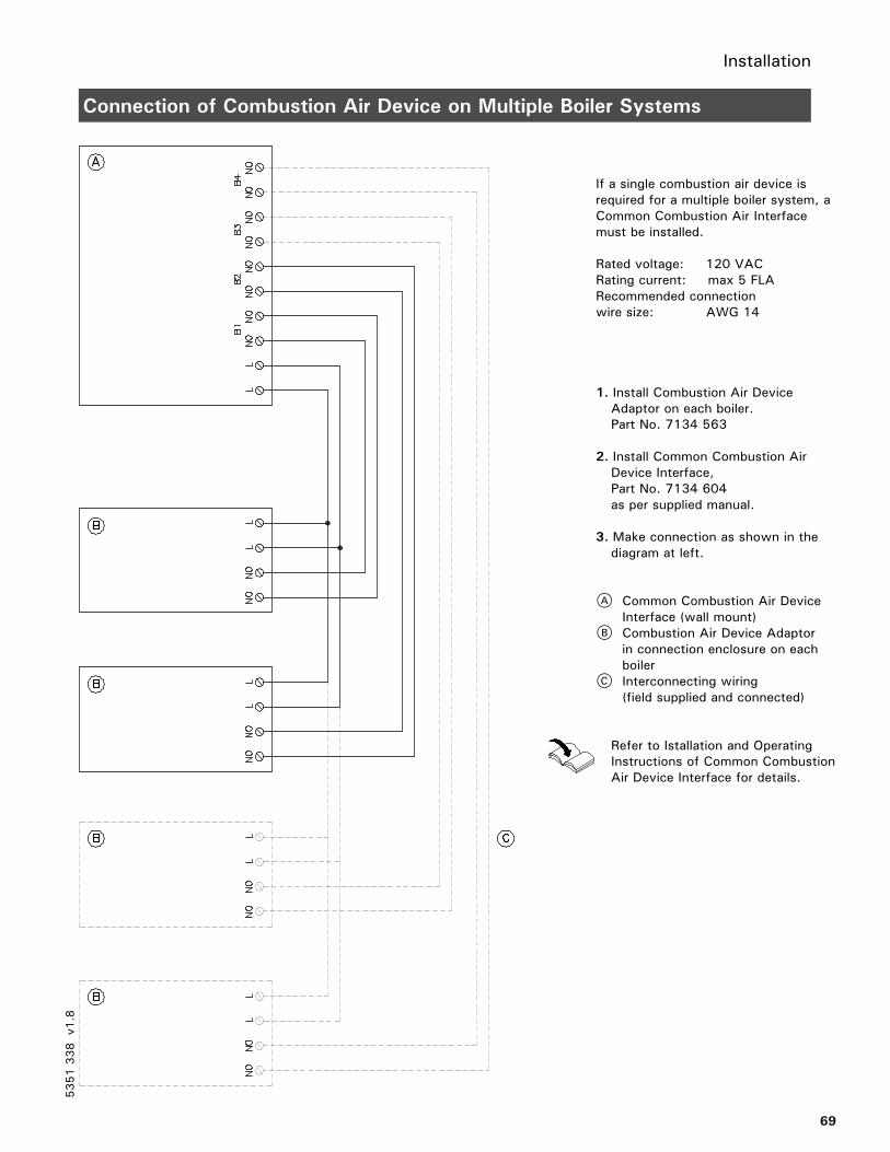
Installation
69
Connection of Combustion Air Device on Multiple Boiler Systems
If a single combustion air device isrequired for a multiple boiler system, aCommon Combustion Air Interfacemust be installed.
Rated voltage: 120 VACRating current: max 5 FLARecommended connectionwire size: AWG 14
1. Install Combustion Air DeviceAdaptor on each boiler.Part No. 7134 563
2. Install Common Combustion AirDevice Interface,Part No. 7134 604as per supplied manual.
3. Make connection as shown in thediagram at left.
A Common Combustion Air DeviceInterface (wall mount)
B Combustion Air Device Adaptorin connection enclosure on eachboiler
C Interconnecting wiring(field supplied and connected)
Refer to Istallation and OperatingInstructions of Common CombustionAir Device Interface for details.
5351338
v1.8

Installation
70
Connection of Single Combustion Air Device on Multiple Boiler Systems
Connection of the combustion air
blower
A Common Combustion Air DeviceInterface
B Combustion air device motor120VAC, 5 FLA max.
C Proving switch rated for 120 VACD Power supply, 120 VAC
¨ Safety instruction!
Provide disconnect means and
overcurrent protection as required
by local codes.
See blower manual for currentrating to correctly select the fuse.
See Common Combustion AirDevice Interface manual forInstallation and Operating details.
1. Disconnect power to control andburner.
2. Make the connections as shownin the diagram.
5351338
v1.8
D

Installation
71
Connection of Combustion Air Damper
Connection of the combustion air
damper
A Common Combustion Air DeviceInterface
B Combustion air device motor120VAC, 5 FLA max
C Proving switch rated for 120 VACD Power supply, 120 VAC
¨ Safety instruction!
Provide disconnect means and
overcurrent protection as required
by local codes.
See damper manual for currentrating to correctly select the fuse.
See Common Combustion AirDevice Interface manual forInstallation and Operating details.
1. Disconnect power to control andburner.
2. Make the connections as shownin the diagram.
5351338
v1.8

Installation
72
Flue Gas Temp. Switch (mandatory for PP(s) material collectors)
(CM2 only)
1. Disconnect power.
2. Remove 150 plug from theVitotronic control and discard.
3. Install new 150 plug supplied(attached to flue gas temperatureswitch).
5351338
v1.8
Please note that the diagram shown
is only a simplified conceptual
drawing of a flue gas temperature
switch. Refer to the manual specific
to the device for interconnection
details.
CAUTION
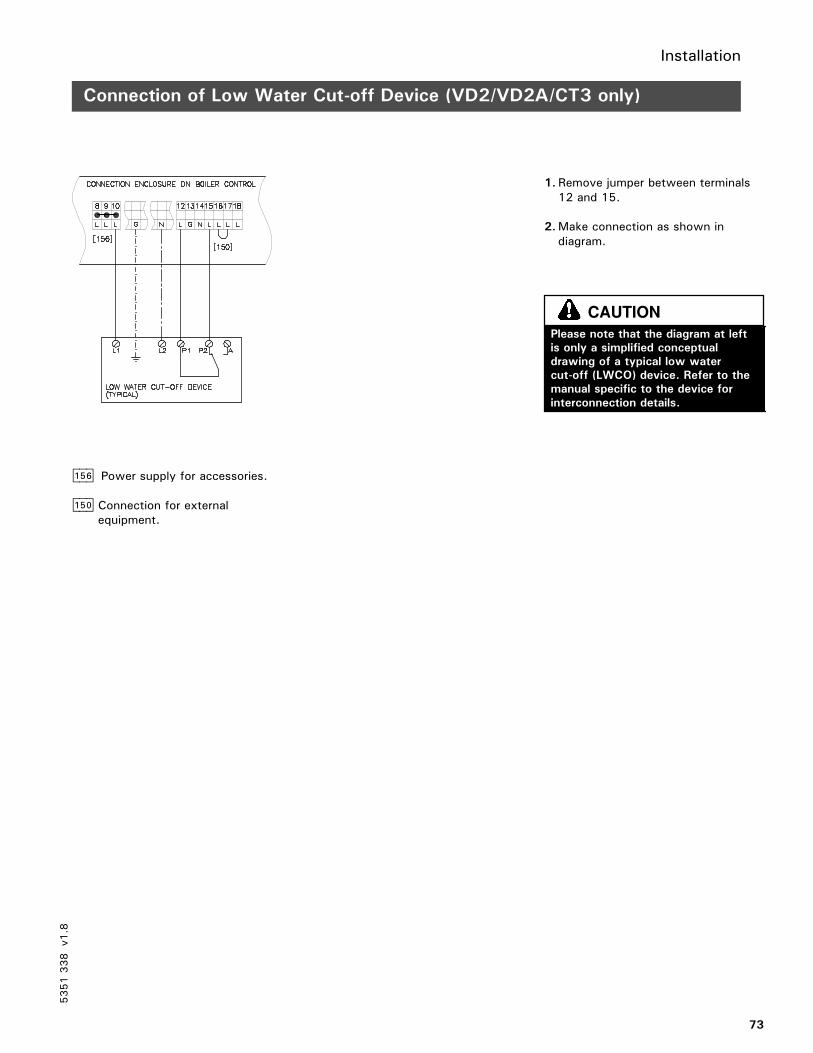
Installation
73
Connection of Low Water Cut-off Device (VD2/VD2A/CT3 only)
aBH Power supply for accessories.
aBÖ Connection for externalequipment.
1. Remove jumper between terminals12 and 15.
2.Make connection as shown indiagram.
5351338
v1.8
Please note that the diagram at left
is only a simplified conceptual
drawing of a typical low water
cut-off (LWCO) device. Refer to the
manual specific to the device for
interconnection details.
CAUTION

Installation
74
Connection of Low Water Cut-off Device (CM2 only)
1. Remove jumper between terminals21 and 22.
2.Make connection as shown indiagram.
5351338
v1.8
Please note that the diagram shown
is only a simplified conceptual
drawing of a typical low water
cut-off (LWCO) device. Refer to the
manual specific to the device for
interconnection details.
CAUTION

Installation
75
Connections to Terminal aBÖ (VD2/VD2A/CT3 only)
A JumperB External shut-off (dry contact)
External shut-off
1. Remove jumper between terminals16 and 17.
2. Connect dry contact.Controlled switch-off takes placewhen the contact is opened.
WARNING
Emergency operation
Move jumper from terminals 16 and 17to terminals 17 and 18.
5351338
v1.8
The terminals should be used for
safety switch-off purposes only (e.g.
through a limit thermostat). See
pages 52 to 59 for details of
controlled switch-off.
During switch-off, there is no frost
protection of the heating system and
the boiler is not kept at the minimum
boiler water temperature.
CAUTION

Installation
76
Connection of the Compiled Failure Alarm Indicator (VD2/VD2A/CT3 only)
Rated voltage: 120 VAC 60 Hz
Rated current: max. 2 FLA
Recommended connection
wire size: AWG 14
1.Disconnect power to control andburner.
2.Connect the compiled failure alarmas shown in the diagram.
A Connect terminal strip inconnection enclosure of boilercontrol
B Visual and/or audible alarmdevice (120 VAC)
5351338
v1.8
A
B

Installation
77
Connection of the Compiled Failure Alarm Indicator (CM2 only)
Rated voltage: 120 VAC 60 Hz
Rated current: max. 2 FLA
Recommended connection
wire size: AWG 14
1.Disconnect power to control andburner.
2.Connect the compiled failure alarmas shown in the diagram.
A Connect terminal strip inconnection enclosure of boilercontrol
B Visual and/or audible alarmdevice (120 VAC)
5351338
v1.8
A
B
9
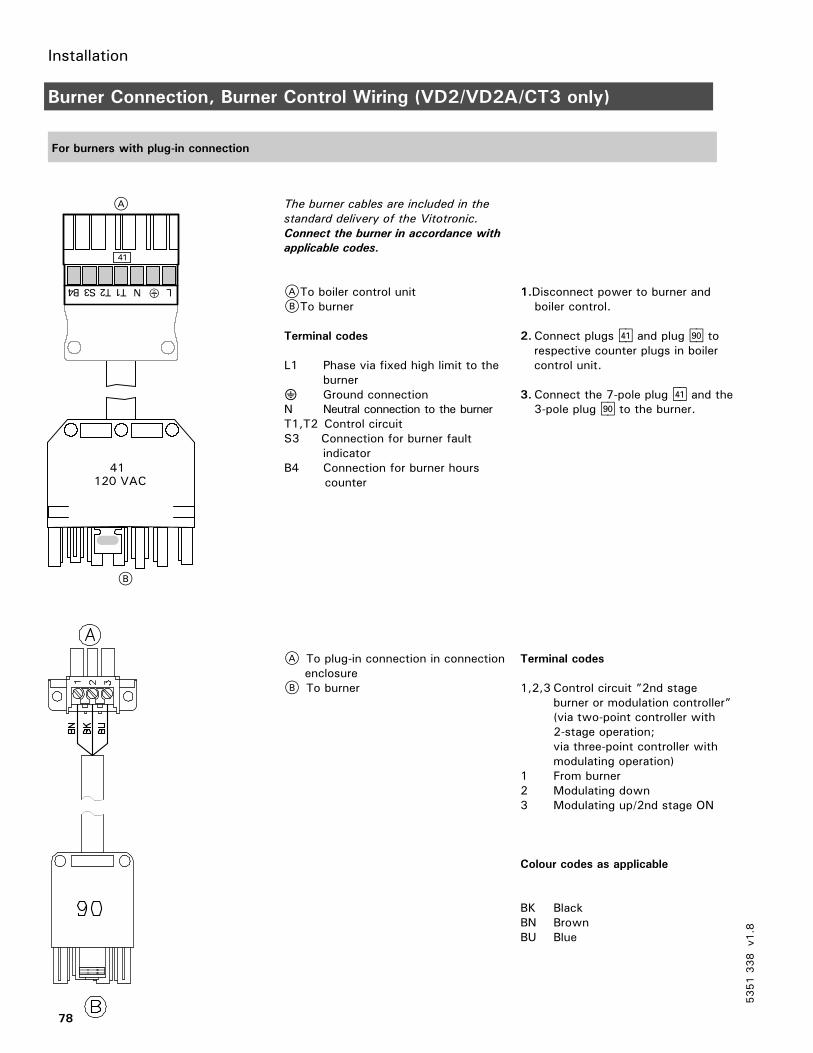
Installation
78
Burner Connection, Burner Control Wiring (VD2/VD2A/CT3 only)
For burners with plug-in connection
The burner cables are included in the
standard delivery of the Vitotronic.
Connect the burner in accordance with
applicable codes.
ATo boiler control unitBTo burner
Terminal codes
L1 Phase via fixed high limit to theburner
? Ground connectionN Neutral connection to the burnerT1,T2 Control circuitS3 Connection for burner fault
indicatorB4 Connection for burner hours
counter
A To plug-in connection in connectionenclosure
B To burner
1.Disconnect power to burner andboiler control.
2.Connect plugs fA and plug lÖ torespective counter plugs in boilercontrol unit.
3.Connect the 7-pole plug fA and the3-pole plug lÖ to the burner.
Terminal codes
1,2,3 Control circuit ”2nd stageburner or modulation controller”(via two-point controller with2-stage operation;via three-point controller withmodulating operation)
1 From burner2 Modulating down3 Modulating up/2nd stage ON
Colour codes as applicable
BK BlackBN BrownBU Blue
5351338
v1.8
A
B
41120 VAC

Installation
79
Burner Connection, Burner Control Wiring (VD2/VD2A/CT3 only) (continued)
Write the terminal numbers ormarkings on the drawing for futurereference.
Burner power supply not shown.
A Control unit(Legend: see wiring diagram)
B 2nd stage or modulating *1
C Hours counter, stage 1 *1
D Burner fault indicator *1
E Control circuit, stage 1/basic load *1
F Burner
fÖ Power supply connection of controlunit 120 VAC
fA Burner, 1st stagelÖ Burner, 2nd stage
aBÖ Plugs for external equipmenta External safety devices(remove jumper when connecting)b External controlled switch-off(remove jumper when connecting)
aBA Safety circuit. Emergencyshut-off
*1 Refer to burner manufacturer’s instruction on detailed connections for Viessmann controls.
5351338
v1.8
This is a generic connection drawing
only! Follow the burner
manufacturer’s connection drawings
for Viessmann controls.
CAUTION
a b
Plug connectionlocated on theDIN rail. See page42 for details.

Installation
80
Burner Connection, Burner Control Wiring (VD2/VD2A/CT3 only) (continued)
Burner motor power supply connection
(continued)
For burners with 240 VAC, 1PH power
supply and connection in conduit.
See burner manual for correct fuseand wire gauge sizing, and specificconnections for Viessmann controls.
1.Disconnect power to burner andboiler control.
2.Connect 240 VAC power to theterminals 21, 22 and 23 on theDIN rail inside the connectionenclosure. Provide fuseabledisconnect means according tolocal codes.
3.Connect supplied power cable tothe motor terminals on the burner.
4.Connect cable plug to the socketon the DIN rail in the connectionenclosure.
A Burner motor power supply240 VAC, 1PH
B Connection terminals and pluginside connection enclosure
C Cable and conduit- factory suppliedD BurnerE Motor starterF Burner motorG Connection enclosure on boiler
control
5351338
v1.8

Installation
81
Burner Connection, Burner Control Wiring (VD2/VD2A/CT3 only) (continued)
Burner motor power supply connection
(continued)
For burners with 3PH 208, 460 or
575V power supply.
See burner manual for correct fuseand wire gauge sizing, and specificconnections for Viessmann controls.
1.Disconnect power to burner andboiler control.
2.Connect 3PH power to theterminals 21, 22, 23 and 24 onthe DIN rail inside the connectionenclosure. Provide fuseabledisconnect means according tolocal codes.
3.Connect supplied power cable tothe motor terminals on the burner.
4.Connect cable plug to the socketon the DIN rail in the connectionenclosure.
A Burner motor power supply 3PH208, 460 or 575V
B Connection terminals and pluginside connection enclosure
C Cable and conduit - factorysupplied
D BurnerE Motor starterF OverloadG Burner motorH Connection enclosure
5351338
v1.8
During commissioning check for
correct motor rotation. If motor
rotates in opposite direction than
indicated on the burner, disconnect
power supply and reverse wires BK1
and BK2 on the burner terminals.
CAUTION

Installation
82
Power Supply Connection, Boiler Control (VD2/VD2A/CT3 only)
Legend
L: LineN: NeutralG: GroundA Power supply 120 VAC, 1 PH .
Provide disconnect means andovercurrent protection as per localcodes
B Terminals [40]C Connection enclosure
1. Ensure that the main power supplyto the control contains overcurrentprotection with a maximum ratingof 15 A and 2 pole disconnect.
2. Connect power supply wire to theConnection fÖ terminals 11, N andG on the DIN rail inside theconnection enclosure.
5351338
v1.8
The control must be grounded.
Ensure that “L”, “N” and “G” are not
interchanged.
CAUTION

Installation
83
Burner Connection, Burner Control Wiring (CM2 only)
For burners with plug-in connection
The burner cables are included in the
standard delivery of the Vitotronic.
Connect the burner in accordance with
applicable codes.
ATo boiler control unitBTo burner interface
Terminal codes
L1 Phase via fixed high limit to theburner
? Ground connectionN Neutral connection to the burnerT1,T2 Control circuitS3 Connection for burner fault
indicatorB4 Connection for burner hours
counter
A To plug-in connection in connectionenclosure
B To burner interface
1.Disconnect power to burner andboiler control.
2.Connect plugs fA and plug lÖ torespective counter plugs in boilercontrol unit.
3.Connect the 7-pole plug fA andthe 3-pole plug lÖ to the burner.
Terminal codes
1,2,3 Control circuit ”2nd stageburner or modulation controller”(via two-point controller with2-stage operation;via three-point controller withmodulating operation)
1 From burner2 Modulating down3 Modulating up/2nd stage ON
Colour codes as applicable
BK BlackBN BrownBU Blue
5351338
v1.8
A
B
A
B

Start-up
84
Procedure (overview)
Page
1. Controls and indicators 85. . . . . . . . . . . . . . . . . . . . . . . . . . . . . . . . . . . . . . . . . . . . . . . . . . . . . . . . . . . . . . . . . . . . . . . . . . . . . .
2. Check the fixed high limit 86. . . . . . . . . . . . . . . . . . . . . . . . . . . . . . . . . . . . . . . . . . . . . . . . . . . . . . . . . . . . . . . . . . . . .
3. Integrate the control unit in the LON BUS system
(in conjunction with heating circuits connected downstream) 87. . . . . . .
4. Carry out participant check 88. . . . . . . . . . . . . . . . . . . . . . . . . . . . . . . . . . . . . . . . . . . . . . . . . . . . . . . . . . . . . . . . . . .
5.Match the control unit to the system type 89. . . . . . . . . . . . . . . . . . . . . . . . . . . . . . . . . . . . .
6. Check outputs (actuators) and sensors 89. . . . . . . . . . . . . . . . . . . . . . . . . . . . . . . . . . . . . . . . . . .
7.Match the coding addresses 90. . . . . . . . . . . . . . . . . . . . . . . . . . . . . . . . . . . . . . . . . . . . . . . . . . . . . . . . . . . . . . . . .
5351338
v1.8
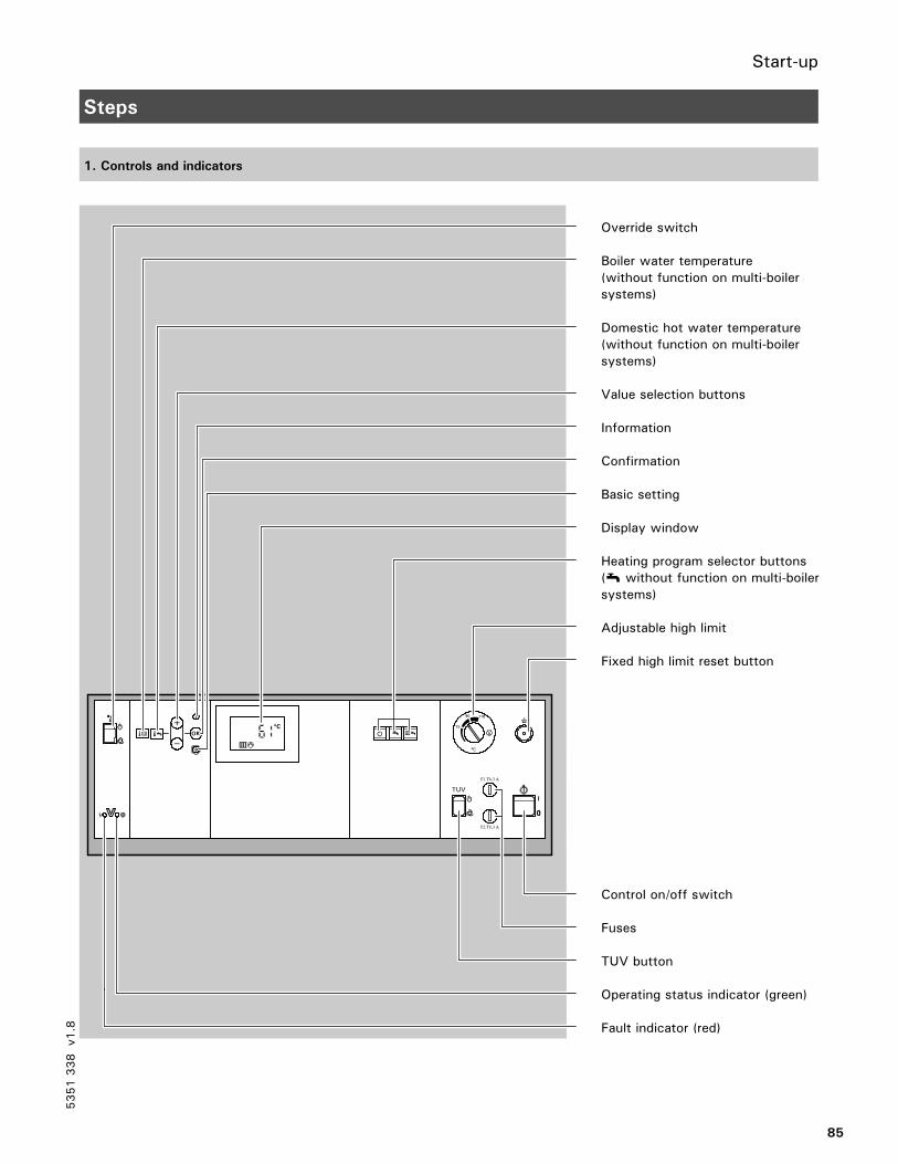
Start-up
85
Steps
1. Controls and indicators
Override switch
Boiler water temperature(without function on multi-boilersystems)
Domestic hot water temperature(without function on multi-boilersystems)
Value selection buttons
Information
Confirmation
Basic setting
Display window
Heating program selector buttons(w without function on multi-boilersystems)
Adjustable high limit
Fixed high limit reset button
Control on/off switch
Fuses
TUV button
Operating status indicator (green)
Fault indicator (red)
5351338
v1.8
F1 T6,3 A
F2 T6,3 A
TUV

Start-up
86
Steps (continued)
2. Check the fixed high limit
The check is made via the ”TUV button” (see page 85).
When making the check, the ”TUV”button must be kept continuouslypressed.A minimum supply is required duringthe check.The minimum amount of recirculatedwater should be 10% of the amountrecirculated at the rated load.The amount of heat consumed shouldbe reduced as far as possible.The adjustable high limit ”R” isbridged. The burner is switched onuntil the boiler water temperaturereaches the safety temperature andthe fixed high limit operates.When the burner is switched off bythe fixed high limit, release the ”TUV”button, wait until the boiler watertemperature has fallen 15 to 20°C / 27to 36°F below the selected safetytemperature and then reset the fixedhigh limit by pressing the ”E” button.
5351338
v1.8

Start-up
87
Steps (continued)
3. Integrate the control unit in the LON BUS system Single-boiler system only
The LON communication module
(accessory) must be inserted
(see page 111).
Set the LON participant number
Set the LON participant number viacoding address ”77” in coding 1(factory setting: ”77: 1”).
See page 115 for coding 1.
Please note:
The same number must not be
assigned twice within a LON BUS
system.
Update the LON participant list
This is only possible when all participants are connected and the control unit is
coded as the error manager (coding ”79: 1”).
1. Press w and simultaneously forapprox. 2 seconds.
2. Press D.
The participant check is initiated
(see also page 88).
The participant list is updated after
approx. 2 minutes.
The participant check is terminated.
Example of single-boiler system with Vitotronic 050 heating circuit controls and Vitocom connected downstream
Participant No. 1Coding ”77: 1”
Participant No. 10Coding ”77: 10”
Participant No. 11Set coding ”77: 11”
Participant No. 100
Control unit is errormanagerCoding ”79: 1”
Control unit is not errormanagerCoding ”79: 0”
Control unit is not errormanagerCoding ”79: 0”
Unit is error manager
––– Transmit time via LONSet coding ”7b: 1”
Time is received via LONSet coding ”81: 3”
Time is received via LON
––– Transmit outdoortemperature via LONSet coding ”97: 2”
Outdoor temperature isreceived via LONSet coding ”97: 1”
–––
5351338
v1.8
1 2 3 4 5 6 7
Vitotronic 100 Vitotronic 050 Vitotronic 050 Vitocom
LON LON LON

Start-up
88
Steps (continued)
4. Carry out participant check Single-boiler system only
The participant check is used to verify the communication of the system units
connected to the error manager.
Requirements:
The control unit must be coded as the error manager (coding ”79: 1”)
The LON participant number must be coded in all control units (see page 87)
The participant list must be updated in the error manager (see page 87)
1. Press w and simultaneously forapprox. 2 seconds.
Participant numberConsecutive list number
2. Select the required participant withor .
3.Activate the check with .If communication between the twounits is verified, the arrows in thedisplay window stop flashing.If communication is not verified, thedisplay shown on the left appears.
4. To check further participants, followthe steps described in points 2 and3.
5. Press w and simultaneously forapprox. 1 second.
The participant check is initiated.
All 7 arrows appear in the display
window.
The arrows in the display will flash
until the check is completed. The
display window and all lit buttons of
the selected participant flash for
approx. 60 seconds.
Check the LON connection (see page
111).
The participant check is terminated.
5351338
v1.8
1 2 3 4 5 6 7
1 2 3 4 5 6 7
1 2 3 4 5 6 7

Start-up
89
Steps (continued)
5. Match the control unit to the system type
Set the following coding addresses incoding 2:”00” System type”01” Single or multi-boiler system”02” Burner type”03” Oil or gas-fired operation”07” Boiler number”0C” Return temperature raising”0d” Therm-Control is effective for ...”4C” plug sÖ function”4d” plug sL function”4E” plug gS function
See page 117 for coding 2.
6. Check outputs (actuators) and sensors
Carry out relay test
1. Press and simultaneously forapprox. 2 seconds.
2. Select relay outputs with the orbutton.
3. Press .
Relay test is activated.
Relay test is terminated.
The following relay outputs can beselected depending on the systemequipment installed:
Display Relay function
11 Burner/stage 1 ON
12 Burner stage 1 and 2ON/modulation open
13 Burner modulation neutral
14 Burner modulation closed
15 Output 20 ON
16 Output 29 ON
17 Output 52 open
18 Output 52 neutral
19 Output 52 closed
10 DHW pump ON
11 Central fault indicator ON
Check sensors
1. Press .
2. Scan sensors with or .
3. Press .
Scanning of operating statusinformation is activated(see page 97).
Scanning is terminated.
5351338
v1.8
1 2 3 4 5 6 7
1 2 3 4 5 6 7

Start-up
90
Steps (continued)
7. Match the coding addresses
Match control unit to modulating burner
Please note:
The burner must be adjusted. In order to achieve a wide modulation range, the
minimum output should be set as low as possible (take chimney/flue system into
account).
1. Start up the burner.
2. Press 9 and simultaneously forapprox. 2 seconds.
3.With activate the function”Modulating burner open” (display:2) and wait until the actuating driveof the burner is at maximum output.
4. Establish the maximum burneroutput through the fuelconsumption.
5.With activate the function”Modulating burner closed”(display: 4) and measure the time ittakes for the actuating drive of theburner to reach the minimumoutput.
6. Establish the minimum burner output(basic output) through the fuelconsumption.
7.With activate the function”Modulating burner open” (display:2) and, after one-third of the timemeasured in point 5, activate thefunction ”Modulating burner neutral”with (display: 3).
8. Establish the partial output throughthe fuel consumption.
9. Press .
The relay test is activated.
Make a note of the value.
Make a note of the value.
Make a note of the value.
Make a note of the value.
The relay test is terminated.
5351338
v1.8
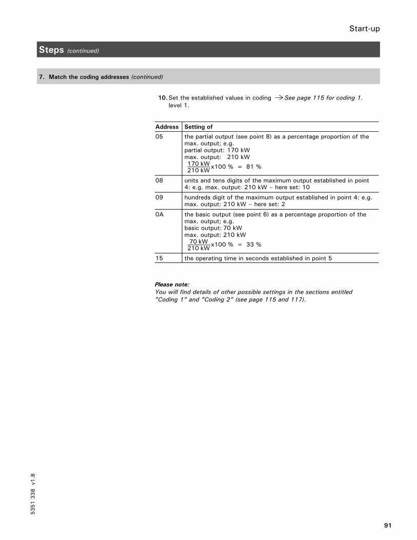
Start-up
91
Steps (continued)
7. Match the coding addresses (continued)
10.Set the established values in codinglevel 1.
See page 115 for coding 1.
Address Setting of
05 the partial output (see point 8) as a percentage proportion of themax. output; e.g.partial output: 170 kWmax. output: 210 kW170 kW210 kW
x100 % = 81 %
08 units and tens digits of the maximum output established in point4: e.g. max. output: 210 kW – here set: 10
09 hundreds digit of the maximum output established in point 4: e.g.max. output: 210 kW – here set: 2
0A the basic output (see point 6) as a percentage proportion of themax. output; e.g.basic output: 70 kWmax. output: 210 kW70 kW210 kW
x100 % = 33 %
15 the operating time in seconds established in point 5
Please note:
You will find details of other possible settings in the sections entitled
”Coding 1” and ”Coding 2” (see page 115 and 117).
5351338
v1.8

Scanning service information
92
Overview of Service Levels
Function Button combination To exit Page
Temperatures, boiler codingcards and scans
Press 9 and rw simultaneouslyfor approx. 2 seconds
Press OK 93
Relay test Press 9 and OK simultaneously forapprox. 2 seconds
Press OK 89
Participant check(in conjunction with LON)
Press w and OK simultaneously forapprox. 2 seconds
Press w and OK simultaneously forapprox. 1 second
88
Operating status information Press Press 97
Service display Press OK 98
5351338
v1.8

Scanning service information
93
Temperatures, Boiler Coding Cards and Scans
1. Press and simultaneously forapprox. 2 seconds.
Access diagnosis level.
2. Select the required data for scanningwith the or button.
3. Press . Exit diagnosis level.
The following values can be scanned depending on the system equipmentinstalled:
Display Meaning Notes
08888 Scan 0 Only in conjunction with LONcommunication module; seepage 94
18888 Scan 1 Only in conjunction with LONcommunication module; seepage 94
28888 Scan 2 Only in conjunction with LONcommunication module; seepage 94
3 65 °C Set-point boiler water tempera-ture (effective set-point valueincluding boiler protection)
–––
h 70 °C Maximum request temperature –––
48888 Scan 4 See page 95
5 55 °C Set-point domestic hot watertemperature
–––
8230 °C Maximum flue gastemperature
See coding address ”1F”; canbe reset to the actual value bypressing D
c1010 Boiler coding card See page 112
b 8d8 Scan b/d See page 95
l8888 Scan L See page 96
o8888 Scan o See page 96
5351338
v1.8

Scanning service information
94
Temperatures, Boiler Coding Cards and Scans (continued)
Scan 0
Scan 1
Scan 25351338
v1.8
8880 8
Software versionCommunication coprocessor
Scan 0
LON participant number
SNVT configurationAutoTool
0toF0
to9
0to9
0
01
8881 8
Node address
System number(only with self-binding)
Subnet address
Scan 1
0toF
0toF0
toF
1
0toF
8882 8
Software versionLON communication module
Number of LONparticipants
Scan 2
0to9
2
0to9
0toF
0toF

Scanning service information
95
Temperatures, Boiler Coding Cards and Scans (continued)
Scan 4
Scan b/d
5351338
v1.8
8884 8
Software versionControl unit
System type
Free
Software versionProgramming unit
Scan 44
1or2
0toF
0toF
Isolation valve0 Closed1 Preheating2 Closing3 Regulating4 Opening5 Open6 Run-on
d
012
b
888b d
Scan d
Free
Scan b
BurnerOFF1st stage/basic load2nd stage/full load

Scanning service information
96
Temperatures, Boiler Coding Cards and Scans (continued)
Scan L
Scan oooo
5351338
v1.8
0 0 0or to to1 9 9
L
888l 8
Scan L
Free
Output reduction(0 to 100 %; 0 = OFF)
0 0to toF F
o
888o 8
Free
Equipment identification code
Scan o
Free

Scanning service information
97
Scanning Service Information
1. Press .
2. Select the required operating statusdata for scanning with the orbutton.
3. Press .
Operating status scanning mode is
activated.
Exit the operating status scanning
mode.
The following operating status information can be scanned depending on thesystem equipment installed:
Display Meaning Notes
0 01 LON participant number Only displayed if LONcommunication module isconnected
3 65 °C Boiler temperature ––
5 50 °C DHW tank temperature(1st DHW tank temperaturesensor)
Only displayed if DHW tanktemperature sensor isconnected
5o 45 °C DHW tank temperature(2nd DHW tank temperaturesensor)
Only displayed if DHW tanktemperature sensor isconnected
6 55 °C Return temperature17A (1st return temperaturesensor)
Only displayed if returntemperature sensor isconnected
8 190 °C Flue gas temperature Only displayed if flue gastemperature sensor isconnected
9 60 °C Return temperature17B (2nd return temperaturesensor)
Only displayed if returntemperature sensor isconnected
63572 h
Burner hours run1st stage
The hours run can be reset to”0” by pressing D. The hoursrun displayed are approximatevalues only
09572 h
Burner hours run2nd stage
The hours run can be reset to”0” by pressing D. The hoursrun displayed are approximatevalues only
30417
Burner starts The number of burner startscan be reset to ”0” bypressing D
5351338
v1.8

Scanning service information
98
Scanning and Resetting the Service Display
Please note:
If a service is carried out before the service display appears, set the coding
address ”24: 1” and then coding address ”24: 0”.
When the limit values selected viacoding addresses ”1F”, ”21” and ”23”(see page 120) are reached, one of thefollowing displays flashes on theprogramming unit:
Display Meaning
a 245 °C Max. flue gastemperature reached
35510 hNumber of burner hoursrun reached
12 u Time interval(e.g. 12 months)reached
1. Scan the service messages with theor button.
2. Press . The service display is turned off.
Please note:
An acknowledged service message
can be displayed again by pressing
(for approx. 3 seconds).
After carrying out maintenance
1. Reset coding ”24: 1”(see page 120) to ”24: 0”.
Please note:
If coding address ”24” is not reset,
the service display will re-appear on
Monday morning.
2. If necessary:Press .Reset burner hours run andnumber of burner starts withthe button.
Press .
3. If necessary:Press andsimultaneously for approx.4 seconds.
Reset maximum flue gastemperature (8) to the actualvalue by pressing .
Press .
See ”Temperatures, boiler coding
cards and scans” on page 93.
See ”Scanning operating status
information” on page 97.
5351338
v1.8

Troubleshooting
99
Troubleshooting Steps
Page
Diagnosis 1. Establish fault message or ascertain behaviour of system
2. Look for the corresponding cause of the fault in the
diagnosis tables 101. . . . . . . . . . . . . . . . . . . . . . . . . . . . . . . . . . . . . . . . . . . . . . . . . . . . . . . . . . . . . . . . . . . . . . . . . . . . . . . . . . . . . . . . . . . . .
Please note:
Retrieve fault codes from the fault memory 100. . . . . . . . . . . . . . . . . . . . . . . . . . . . . . . . . . . . . . . . .
3. Establish the action required in the table
Correction 4. Correct the fault
5351338
v1.8

Troubleshooting
100
Diagnosis
Faults with fault display on the programming unit
The red fault indicator 2 flashes whenever there is a fault.
When a fault message is transmitted,a fault code flashes in the display 1of the programming unit.
Other fault codes which may bestored can be called up by pressingthe or button.
Fault symbol
Fault code
Fault number
The meaning of the fault code is
explained in the table on page 101
onwards.
The fault can be acknowledged by
pressing .The fault message in
the display 1 is blanked out; the
red fault indicator 2 continues to
flash. The central fault indicator
connected to plug gÖ is switched
off.
If an acknowledged fault is not
rectified within 24 hours, the fault
message will re-appear in the
display.
Vitotronic 100 as error manager
A fault on another LON participant isdisplayed as shown:
Fault symbol
LON participant number of the unitwith the fault
”EE” = External fault
To retrieve an acknowledged
fault message
Press for approx. 2 seconds;select the acknowledged fault bypressing the or button.
Fault is displayed.
5351338
v1.8
1 2 3 4 5 6 7

Troubleshooting
101
Diagnosis (continued)
Faults with fault display on the programming unit (continued)
Fault
code in
display
Behaviour of system Cause of fault Action
30 Burner is switched on and off bythe adjustable high limit
Short circuitBoiler temperature sensor
Check boiler temperature sensor (seepage 50)
38 Burner is switched on and off bythe adjustable high limit
Open circuitBoiler temperature sensor
Check boiler temperature sensor (seepage 50)
50 DHW pump ON:set-point boiler temperature =set-point DHW tank temperature,priority controls are cancelledorIn conjunction with DHW heating:Tank heating is switched on and offby Tank temperature sensor 2
Short circuitDHW tank temperature sensor 1
Check DHW tank temperature sensor(see page 51)
51 In conjunction with DHW heating:Tank heating is switched on and offby Tank temperature sensor 1
Short circuitDHW tank temperature sensor 2
Check DHW tank temperature sensor(see page 51)
58 DHW pump ON:set-point boiler temperature =set-point DHW tank temperature,priority controls are cancelledorIn conjunction with DHW heating:Tank heating is switched on and offby Tank temperature sensor 2
Open circuitDHW tank temperature sensor 1
Check DHW tank temperature sensor(see page 51)
59 In conjunction with DHW heating:Tank heating is switched on and offby DHW tank temperature sensor 1
Open circuitDHW tank temperature sensor 2
Check DHW tank temperature sensor(see page 51)
60 No output reductionReturn control openBoiler with maximum temperature
Short circuitTemperature sensor aJA
Check temperature sensor(see page 52)
68 No output reductionReturn control openBoiler with maximum temperature
Open circuitTemperature sensor aJA
Check temperature sensor(see page 52)
70 Shunt pump ON continuously Short circuitTemperature sensor aJB
Check temperature sensor(see page 52)
70In conjunction with DHW heating:Mixing valve of primary circuitclosed, no domestic hot waterheating
Short circuitTemperature sensor aJB
Check temperature sensor(see page 52)
78 Shunt pump ON continuously Open circuitTemperature sensor aJB
Check temperature sensor(see page 52)
78In conjunction with DHW heating:Mixing valve of primary circuitclosed, no domestic hot waterheating
Open circuitTemperature sensor aJB
Check temperature sensor(see page 52)
5351338
v1.8

Troubleshooting
102
Diagnosis (continued)
Faults with fault display on the programming unit (continued)
Fault
code in
display
Behaviour of system Cause of fault Action
aa Controlled operation Therm-Control configurationerror:plug aJA ofTherm-Control temperaturesensor not inserted
Insert plug aJAOn Vitocrossal:Check that coding ”0d: 0” is set.
ab Controlled operation, DHW tankmay be cold
DHW heatingconfiguration error:Coding ”55: 3” is set, butplug aJB is not insertedand/orcoding ”4C: 1” and ”4E: 1”not set
Insert plug aJB and check coding
aCc Controlled operation Return temperature sensorconfiguration error:Coding ”0C: 1” is set, butplug aJA is not insertedand/orcoding ”4E: 0” is not set
Insert plug aJA and check coding
aCd Controlled operation Butterfly valveconfiguration error:Coding ”0C: 2”, ”0C: 3” or”0C: 4” is set,andcoding ”4E: 1” is set
If butterfly valve is installed:Set coding ”4E: 0”If no butterfly valve is installed:Set coding ”0C: 0” or ”0C: 1”
b0 Controlled operation Short circuitFlue gas temperature sensor
Check flue gas temperature sensor(see page 53)
b1 Controlled operation Communication errorProgramming unit
Check connections, if necessaryreplace programming unit
b4 Emissions test mode Internal fault Check electronics board
b5 Controlled operation Internal fault Check electronics board
b6 Operation at constant temperature Invalid hardware code Check the control software circuitboard and confirm the coding address:- Enter coding 2 (see page 117for instructions).
- Change code 8A to 176.- Confirm coding 92:160
b7 Boiler controlled on basis ofadjustable high limit
Internal faultBoiler coding card
Insert boiler coding card or replaceif defective (see page 42)
b8 Controlled operation Open circuitFlue gas temperature sensor
Check flue gas temperature sensor(see page 53)
bf Controlled operation Incorrect LON communicationmodule
Replace LON communicationmodule
c1 Boiler cools down External safety equipment Check connection of plugaBÖ
Check external safetyequipment
5351338
v1.8
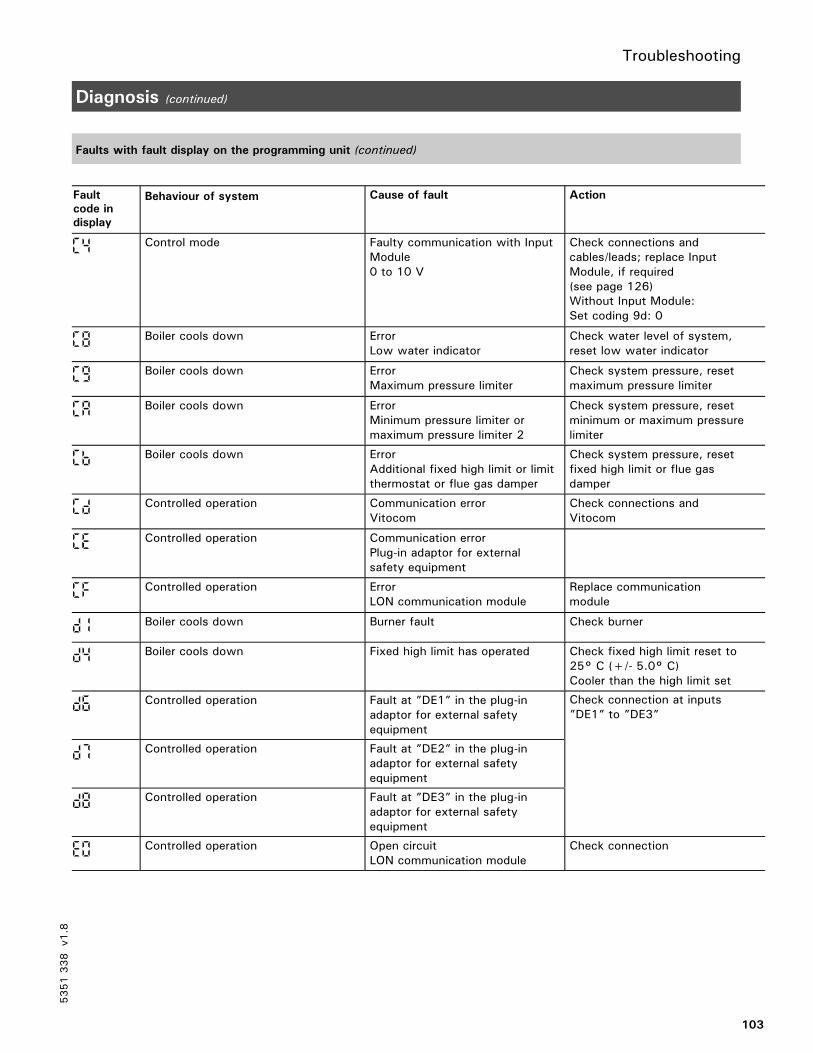
Troubleshooting
103
Diagnosis (continued)
Faults with fault display on the programming unit (continued)
Fault
code in
display
Behaviour of system Cause of fault Action
c4 Control mode Faulty communication with InputModule0 to 10 V
Check connections andcables/leads; replace InputModule, if required(see page 126)Without Input Module:Set coding 9d: 0
c8 Boiler cools down ErrorLow water indicator
Check water level of system,reset low water indicator
c9 Boiler cools down ErrorMaximum pressure limiter
Check system pressure, resetmaximum pressure limiter
ca Boiler cools down ErrorMinimum pressure limiter ormaximum pressure limiter 2
Check system pressure, resetminimum or maximum pressurelimiter
cb Boiler cools down ErrorAdditional fixed high limit or limitthermostat or flue gas damper
Check system pressure, resetfixed high limit or flue gasdamper
cd Controlled operation Communication errorVitocom
Check connections andVitocom
cEe Controlled operation Communication errorPlug-in adaptor for externalsafety equipment
cf Controlled operation ErrorLON communication module
Replace communicationmodule
d1 Boiler cools down Burner fault Check burner
d4 Boiler cools down Fixed high limit has operated Check fixed high limit reset to25° C (+/- 5.0° C)Cooler than the high limit set
d6 Controlled operation Fault at ”DE1” in the plug-inadaptor for external safetyequipment
Check connection at inputs”DE1” to ”DE3”
d7 Controlled operation Fault at ”DE2” in the plug-inadaptor for external safetyequipment
d8 Controlled operation Fault at ”DE3” in the plug-inadaptor for external safetyequipment
e0 Controlled operation Open circuitLON communication module
Check connection
5351338
v1.8

Troubleshooting
104
Diagnosis (continued)
Retrieving fault codes from the fault memory (error history)
All faults which have occurred are stored and can be retrieved by scanning.
The scanning sequence starts with the most recently stored fault code.
1. Press and simultaneouslyfor approx. 2 seconds.
Scanning of error history is
activated.
2.Access the individual fault codesby pressing the or button.
Sequence of
stored fault
codes
Fault code
1 Last (most recent)fault code
.
.
....
10 Last fault code
3. Press .
All stored fault codes can be
deleted by pressing .
Scanning of error history is
terminated.
5351338
v1.8
1 2 3 4 5 6 7

Functional description
105
Boiler Temperature Control
Brief description
The boiler water temperature iscontrolled by switching the burner onand off.The set-point boiler water temperaturevalue is determined by the set-pointsupply temperature values of the boilercircuit (A1), the heating circuits withmixing valve (from Vitotronic 050) andthe set-point supply temperature valuepreset via coding address ”9b” as wellas the set-point domestic hot watertemperature, and is dependent on theboiler and the heating and controlfacilities installed.
In conjunction with Therm-Control:The set-point boiler water temperatureis increased when the temperature fallsbelow the set-point value on the sensorof the Therm-Control.
Coding addresses which influence
the boiler temperature control
02 to 06, 08 to 0b, 13 to 1C.
Functions
The boiler water temperature ismeasured via a multiple sensor well bythree sensors separately:Fixed high limit FHL(liquid expansion)
Adjustable high limit AHL(liquid expansion)
Boiler temperature sensor BTS(change in resistance PT 500)
Upper limits of control range
Fixed high limit FHL110°C / 230°F, can be adjusted to100°C / 212 or 230°F
Adjustable high limit AHL95°C/ 203°F, can be adjusted to100°C / 212°F
Electronic maximum limitSetting range: 20 to 127°C /68 to 261°FThe maximum limit for the boilerwater temperature is defined incoding address ”06”.
Lower limit of control range
The control unit regulates the boilerwater temperature in normaloperation and in the frost protectionmode according to the boilerconcerned (boiler coding card).
Control sequence
Boiler temperature falls
The burner override signal is set for aboiler water temperature setpoint valueof –2°C / -4°F, and the burner startsits own monitoring program. Dependingon the range of additional controlfacilities and the method of firing,burner override can be delayed by afew minutes.
Boiler temperature rises
The switch-off point of the burner isdefined by the switch-off differential(coding address ”13”).
5351338
v1.8
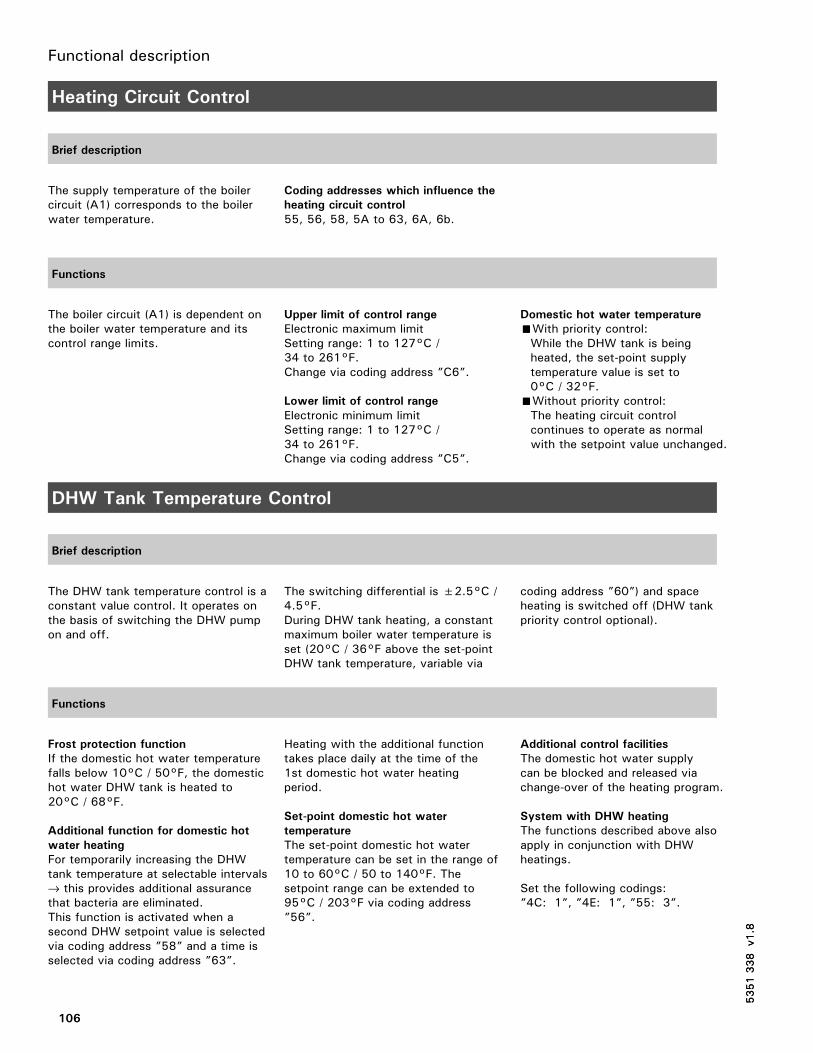
Functional description
106
Heating Circuit Control
Brief description
The supply temperature of the boilercircuit (A1) corresponds to the boilerwater temperature.
Coding addresses which influence the
heating circuit control
55, 56, 58, 5A to 63, 6A, 6b.
Functions
The boiler circuit (A1) is dependent onthe boiler water temperature and itscontrol range limits.
Upper limit of control range
Electronic maximum limitSetting range: 1 to 127°C /34 to 261°F.Change via coding address ”C6”.
Lower limit of control range
Electronic minimum limitSetting range: 1 to 127°C /34 to 261°F.Change via coding address ”C5”.
Domestic hot water temperature
With priority control:While the DHW tank is beingheated, the set-point supplytemperature value is set to0°C / 32°F.
Without priority control:The heating circuit controlcontinues to operate as normalwith the setpoint value unchanged.
DHW Tank Temperature Control
Brief description
The DHW tank temperature control is aconstant value control. It operates onthe basis of switching the DHW pumpon and off.
The switching differential is ±2.5°C /4.5°F.During DHW tank heating, a constantmaximum boiler water temperature isset (20°C / 36°F above the set-pointDHW tank temperature, variable via
coding address ”60”) and spaceheating is switched off (DHW tankpriority control optional).
Functions
Frost protection function
If the domestic hot water temperaturefalls below 10°C / 50°F, the domestichot water DHW tank is heated to20°C / 68°F.
Additional function for domestic hot
water heating
For temporarily increasing the DHWtank temperature at selectable intervals→ this provides additional assurancethat bacteria are eliminated.This function is activated when asecond DHW setpoint value is selectedvia coding address ”58” and a time isselected via coding address ”63”.
Heating with the additional functiontakes place daily at the time of the1st domestic hot water heatingperiod.
Set-point domestic hot water
temperature
The set-point domestic hot watertemperature can be set in the range of10 to 60°C / 50 to 140°F. Thesetpoint range can be extended to95°C / 203°F via coding address”56”.
Additional control facilities
The domestic hot water supplycan be blocked and released viachange-over of the heating program.
System with DHW heating
The functions described above alsoapply in conjunction with DHWheatings.
Set the following codings:”4C: 1”, ”4E: 1”, ”55: 3”.
5351338
v1.8
5351338
v1.8

Functional description
107
DHW Tank Temperature Control (continued)
Control sequence
DHW tank temperature falls
(Set-point value –2.5°C / - 4.5°F,selectable via coding address ”59”)The set-point boiler water temperatureis set 20°C / 36°F higher than theDHW temperature set-point value(selectable via coding address ”60”).
The DHW pump is switched onimmediately (Coding ”61: 1”).
Boiler temperature-dependent switchingof the DHW pump(Coding ”61: 0”):The circulation pump is switched onwhen the boiler water temperature is7°C / 13°F higher than the domestichot water temperature.
DHW tank temperature rises
(Set-point value +2.5°C / 4.5°F)The boiler water temperature set-pointvalue is reset to the valuedetermined by the set-point supplytemperature of the boiler circuit.
When the DHW tank has beenheated up, the DHW pump continuesto run (coding ”62: 10”) until- the temperature differencebetween the boiler water anddomestic hot water is less than7°C / 13°F or
- the set-point boiler watertemperature selected through theset-point supply temperature of theboiler circuit is reachedor
- the set-point domestic hot watertemperature is exceeded by5°C / 9°F.
The max. run-on time is 15 minutes(selectable via coding address ”62”).
DHW pump without run-on time(Coding ”62: 00”):The circulation pump is switched offimmediately.
With adaptive DHW tank heating(Coding ”55: 1”):Adaptive DHW tank heating takesinto account the rate at which thetemperature increases duringdomestic hot water heating.It also takes into account whetherthe boiler must supply heat for spaceheating purposes after heating up theDHW tank or whether the residualheat of the boiler should betransferred to the DHW tank.The control unit determines theswitch-off time of the burner and thecirculation pump accordingly so thatthe set-point domestic hot watertemperature is not substantiallyexceeded after DHW tank heating iscompleted.
5351338
v1.8

Additional information
108
Overview
Page
Technical Data 105
System Components
Line voltage motherboard 105. . . . . . . . . . . . . . . . . . . . . . . . . . . . . . . . . . . . . . . . . . . . . . . . . . . . . . . . . . . . . . . . . . . . . . . . . . . . . .
Low-voltage motherboard 105. . . . . . . . . . . . . . . . . . . . . . . . . . . . . . . . . . . . . . . . . . . . . . . . . . . . . . . . . . . . . . . . . . . . . . . . . . . . . . .
Power supply unit board 106. . . . . . . . . . . . . . . . . . . . . . . . . . . . . . . . . . . . . . . . . . . . . . . . . . . . . . . . . . . . . . . . . . . . . . . . . . . . . . .
Electronics board 106. . . . . . . . . . . . . . . . . . . . . . . . . . . . . . . . . . . . . . . . . . . . . . . . . . . . . . . . . . . . . . . . . . . . . . . . . . . . . . . . . . . . . . . . . . . . . .
Optolink/override switch board 106. . . . . . . . . . . . . . . . . . . . . . . . . . . . . . . . . . . . . . . . . . . . . . . . . . . . . . . . . . . . . . . . . . .
Programming unit 107. . . . . . . . . . . . . . . . . . . . . . . . . . . . . . . . . . . . . . . . . . . . . . . . . . . . . . . . . . . . . . . . . . . . . . . . . . . . . . . . . . . . . . . . . . . . . .
Fuse box 107. . . . . . . . . . . . . . . . . . . . . . . . . . . . . . . . . . . . . . . . . . . . . . . . . . . . . . . . . . . . . . . . . . . . . . . . . . . . . . . . . . . . . . . . . . . . . . . . . . . . . . . . . . . . . .
LON communication module 107. . . . . . . . . . . . . . . . . . . . . . . . . . . . . . . . . . . . . . . . . . . . . . . . . . . . . . . . . . . . . . . . . . . . . . .
Boiler coding card 108. . . . . . . . . . . . . . . . . . . . . . . . . . . . . . . . . . . . . . . . . . . . . . . . . . . . . . . . . . . . . . . . . . . . . . . . . . . . . . . . . . . . . . . . . . . .
Fuses 108. . . . . . . . . . . . . . . . . . . . . . . . . . . . . . . . . . . . . . . . . . . . . . . . . . . . . . . . . . . . . . . . . . . . . . . . . . . . . . . . . . . . . . . . . . . . . . . . . . . . . . . . . . . . . . . . . . . . .
TUV button 109. . . . . . . . . . . . . . . . . . . . . . . . . . . . . . . . . . . . . . . . . . . . . . . . . . . . . . . . . . . . . . . . . . . . . . . . . . . . . . . . . . . . . . . . . . . . . . . . . . . . . . . . .
Fixed high limit 109. . . . . . . . . . . . . . . . . . . . . . . . . . . . . . . . . . . . . . . . . . . . . . . . . . . . . . . . . . . . . . . . . . . . . . . . . . . . . . . . . . . . . . . . . . . . . . . . . .
Adjustable high limit 109. . . . . . . . . . . . . . . . . . . . . . . . . . . . . . . . . . . . . . . . . . . . . . . . . . . . . . . . . . . . . . . . . . . . . . . . . . . . . . . . . . . . . . .
Input module 0 to 10V 110. . . . . . . . . . . . . . . . . . . . . . . . . . . . . . . . . . . . . . . . . . . . . . . . . . . . . . . . . . . . . . . . . . . . . . . . . . . . . . . . . .
Resetting codings to the factory setting 110. . . . . . . . . . . . . . . . . . . . . . . . . . . . . . . . . . . . . . . . . . . . . . . .
Coding 1
Call up coding level 1 115. . . . . . . . . . . . . . . . . . . . . . . . . . . . . . . . . . . . . . . . . . . . . . . . . . . . . . . . . . . . . . . . . . . . . . . . . . . . . . . . . . . . .
Codings 115. . . . . . . . . . . . . . . . . . . . . . . . . . . . . . . . . . . . . . . . . . . . . . . . . . . . . . . . . . . . . . . . . . . . . . . . . . . . . . . . . . . . . . . . . . . . . . . . . . . . . . . . . . . . . . . .
Coding 2
Call up coding level 2 117. . . . . . . . . . . . . . . . . . . . . . . . . . . . . . . . . . . . . . . . . . . . . . . . . . . . . . . . . . . . . . . . . . . . . . . . . . . . . . . . . . . . .
Reset codings to factory settings 117. . . . . . . . . . . . . . . . . . . . . . . . . . . . . . . . . . . . . . . . . . . . . . . . . . . . . . . . . . . . .
Overview of all codings 117. . . . . . . . . . . . . . . . . . . . . . . . . . . . . . . . . . . . . . . . . . . . . . . . . . . . . . . . . . . . . . . . . . . . . . . . . . . . . . . . .
Wiring Diagrams
Overview 121. . . . . . . . . . . . . . . . . . . . . . . . . . . . . . . . . . . . . . . . . . . . . . . . . . . . . . . . . . . . . . . . . . . . . . . . . . . . . . . . . . . . . . . . . . . . . . . . . . . . . . . . . . . . .
Low-voltage motherboard 121. . . . . . . . . . . . . . . . . . . . . . . . . . . . . . . . . . . . . . . . . . . . . . . . . . . . . . . . . . . . . . . . . . . . . . . . . . .
Line voltage motherboard 124. . . . . . . . . . . . . . . . . . . . . . . . . . . . . . . . . . . . . . . . . . . . . . . . . . . . . . . . . . . . . . . . . . . . . . . . . . . .
Parts List
GCI Series 126
5351338
v1.8

Additional information
109
Technical Data
Rated voltage: 120 V~Rated frequency: 60 HzRated actual: 2 x 6 A~Powerconsumption: 10 WProtectionclass: IDegree ofprotection: IP 20 D to EN
60 529, to beguaranteed bymounting/integration
Ambienttemperatureduringoperation: 0 to 40°C /
32 to 104°FFor use in boilerrooms (normalambient conditions)
duringstorage andtransport: –20 to 65°C /
-4 to 149°F
Relay outputs at 120 V~ forcontroloutput sÖ: 2 FLA, 120 VAC*1
circulation pumpfor heating theDHW tank sA: 2 FLA, 120 VAC*1
shunt pump orboiler circuitpump sL: 2 FLA, 120 VAC*1
central faultindicator gÖ: 2 FLA, 120 VAC*1
boiler isolationvalve gS: 0.1 FLA, 120 VAC*1
orreturn valve 0.15 FLA, 24 VAC
burnerconnection fA: 4 FLA 120 VACconnection lÖ:– 2-stage: 0.5 FLA, 120 VAC– modulating: 0.1 FLA, 120 VAC
*1 Total max. 6 A 120 VAC
System Components
Line voltage motherboard, Part No. 7165 792
The motherboard contains:relays and outputs for activatingthe pumps, the control elementsand the burner
plug-in location for power supplyunit board and boiler control section.
Low-voltage motherboard, Part No. 7820 290
The motherboard contains:plugs for sensors, communicationconnections and external equipment
plug-in locations for electronicsboard, LON communication module,Viessmann 2-wire BUScommunication module,programming unit, boiler codingcard and Optolink board.
5351338
v1.8

Additional information
110
System Components (continued)
Power supply unit board, 120 VAC Part No. 7823 991
The power supply unit board containsthe low-voltage supply for the entireelectronics.
Electronics board, Part No. 7828 193
The board contains the microprocessorwith the software.
When replacing the board:1.Make a note of codings and settingson the control unit.
2. Replace the board.3. Set coding ”8A:176” and setcod-ing address ”92” (not listed inthe overview) to ”92:160”.
Optolink/override switch board, Part No. 7820 165
The circuit board contains:Operating status indicatorFault indicatorOptolink laptop interfaceOverride switch
Override switch for flue gasmeasurements with the boiler operatedwith constant boiler water temperaturefor a short time.
The following functions are triggered inthe ”h” setting:The burner is switched on(this can be delayed if the systemincorporates a fuel preheater or fluegas damper)
All pumps are switched onThe boiler water temperature iscontrolled by the adjustable high limit”R”.
5351338
v1.8

Additional information
111
System Components (continued)
Programming unit, Part No. 7823 990
The programming unit is inserted in thecontrol unit.
For setting:heating programset-point values
For displaying:temperaturesoperating status informationfaults
Fuse box, Part No. 7820 175
The fuse box contains:fixed high limitadjustable high limitfusesheating system switchTUV button
LON communication module, Part No. 7172 173 Accessory
The communication module is insertedin the control unit.Interruption of communication isindicated.
1 terminal resistor is inserted on eachof the first and last control unit.
A Control unit or VitocomB Connecting cable for data transfer
between the control units (part ofstandard delivery or accessory)
C Terminal resistor,(Part No. 7143 497, see Vitotronic050 or Vitotronic 333)
D Plug-in locations for B and C
5351338
v1.8
D
D
LON
LON
LON
LON
B BC
LON
LON
C
A AA

Additional information
112
System Components (continued)
Boiler coding card
Vitotronic 200in conjunction with
Boiler codingcard
Part No.
Vitocrossal 300, Type CT3 1040 7820 144
Vitorond 200, Type VD2/VD2A 1020 7820 142
Vitocrossal 200, Type CM2 1041 7820 145
Fuses
F1: 6.3 A, 250 V for protectingthe control elements, pumps andelectronics.Mounting location: see drawing.
F2: T6.3 A, 250 V for protectingthe burner.Mounting location: see drawing.
5351338
v1.8
F2
F1

Additional information
113
System Components (continued)
TUV button, Part No. 7819 314
For checking the fixed high limit.
See description on page 86.
Fixed high limit, Part No. 7820 036
Type STW 56.10525.570, make: EGO, DIN STB (STW) 106095
or
EM-80-V-TK/b7-1 60002843, make: Juchheim, DIN STB 82699
The fixed high limit has a factory setting of 120°C / 248°F.
Electromechanical temperature switch based on the liquid expansion principle
with interlock
Intrinsically safe; interlocking also takes place if the capillary tube is leaking or
if ambient temperatures are below –10°C / 14°F
Limits the boiler water temperature to the maximum permissible value by
cutting out and interlocking
Can be adjusted with the slotted screw A at the rear of the unit to 110 and
99 °C / 230 and 210 °F (cannot be reset to 120°C / 248 °F once adjusted)
Reset unit by pressing the reset button ”E” on the front of the programming
unit if the temperature has fallen approx. 15 K below the shut down temperature
Central fastening M 10, capillary 3600 mm long
Tests:
Electrical to VDE 0701 standard
Functional check via TEST button
Adjustable high limit, Part No. 7817 531
Type TR 55.18029.020, make: EGO, DIN TR 110397
or
EM-1-V-TK/b1 60002846, make: Juchheim, DIN TR 77798
The adjustable high limit has a factory setting of 95°C / 203°F
Electromechanical temperature switch based on the liquid expansion principle
Controls the maximum boiler water temperature (e.g. in emissions test mode)
Can be adjusted to 100 and 110°C / 212 and 230°F by altering the setting
of the stop dial or by removing the cams
Set the lower limit at least 20°C / 36°F higher than the domestic hot water
temperature, the upper limit at least 15°C / 27°F lower than the fixed high limit.
Adjusting shaft 6 mm / 0.27 inches, flat topped
Adjusting knob pushed onto shaft from front
Capillary 3600 mm / 141.7 inches long
Sensor 3 mm / 0.1inches thick, 180 mm / 7.1inches long
Tests:
Electrical to VDE 0701 standard
Functional check via emissions test mode
5351338
v1.8
IMPORTANT

Additional information
114
System Components (continued)
Input Module 0 to 10 V, Part No. 7134 561
From software version 7 of Vitocontrol-S, VD2/CT3, the Input Module can be connected (software version via scan 2:1st digit, display ≥7).
For external control of the boiler/supply temperature via a 0 to 10VDC signal10 to 100˚C or 30 to 120˚F50 to 212˚C or 86 to 248˚Forto signal reduced mode and regulate a heating circuit pump to a lower speed.
fÖ Power connectionaVF 0 to 10VDC inputaVG KM BUS to control unitaBJ Potential free output contact
A Power supply(provide disconnect if required bycode)
B DIP switch (see table)
DIP switch Function
1 to 3:1:2:3:4:4:
OFFONONONONOFF
Switch for pre-set valueReduced mode – system circuit A1Reduced mode – mixing valve circuit M2Reduced mode – mixing valve circuit M3Pre-set value default 10 to 100˚C / 50 to 212˚FPre-set value default 30 to 120˚C / 86 to 248˚F
Please note:
Amongst switches 1 to 3, only one switch may be set to ON.
Resetting codings to the factory setting
1. Press w and rw simultaneouslyfor approx. two seconds, until thefirst two arrows appear in thedisplay.
2. Press D.
5351338
v1.8
OFF
A
Electronics24V
5V
L1
40
120 VAC
157 144 145
N S Ö P 1 2 3 1 2 3
1 2 3 4
ONF150mA
B
_ +
(slow)
1 2 3 4 5 6 7

Additional information
115
Coding 1
Call up coding level 1
1. Press and simultaneously forapprox. 2 seconds.
Access coding level 1.
The first arrow appears in the
display.
2.Call up the required coding addresswith the or button;press to confirm.
3.Change the value with the orbutton; press to confirm.
4. Press and simultaneously forapprox. 1 second.
Address flashes.
Value flashes.
The value is stored and stops flashing
for approx. 2 seconds. Then the
address flashes and further addresses
can now be selected with the orbutton.
Exit coding level 1.
Codings
Coding as per
factory setting
Address: Value
Function New coding
Address:Value
Possible change
00: 1 System
type
System circuit A1without domestic hot waterheating
00: 2 System circuit A1with domestic hot water heating
01: 1 System
type
Single-boiler system 01: 2 Multi-boiler system with cascade controlvia LON BUS (e.g. Vitotronic 333, TypeMW1)
01: 3 Multi-boiler system with cascade controlvia switch contacts (input aVD and aVH)or 0-10V input module
02: 1 Boiler/
burner
Operation with two-stageburner
02: 0 Operation with single-stage burner02: 1 Boiler/
burner
Operation with two-stageburner 02: 2 Operation with modulating burner
03: 0 Boiler/
burner
Gas-fired operation 03: 1 Oil-fired operation(coding cannot be reset)
05: 70 Burner
(mod.)
Burner curve 05: 0 Burner curve linear05: 70 Burner
(mod.)
Burner curve
05: 1to05: 99
Burner curve not linear:
Partial output in kW (at g of theOperatingtime of the actuating drive)Max. output in kW= Partial output in %
x100%
06: 87 Boiler/
burner
Max. limit of boiler watertemperature set to87°C / 189°F
06: 20to06:127
Maximum boiler water temperature limitvariable between20 and 127°C / 68°F and 261°F
5351338
v1.8

Additional information
116
Coding 1 (continued)
Codings (continued)
Coding as per
factory setting
Address: Value
Function New coding
Address:Value
Possible change
07: 1 Boiler Boiler sequence number in multi-boiler system (in conjunction withcoding address ”01”)
07: 2to07: 4
Boiler sequence number in multi-boilersystem (in conjunction with codingaddress ”01”)
08:*1 Burner
(mod.)
Max. output of burner in kW 08: 0to08: 99
Maximum output variable from0 to 99 kW;1 increment = 1 kW
09:*1 Burner
(mod.)
Max. output of burner in kW 09: 0bis09:199
Maximum output variable from0 to 19900 kW:1 increment = 100 kW
0A:*1 Burner
(mod.)
Basic output of burner in % 0A: 0to0A:100 Basic output in %
Basic output in kWMax. output in kW
x100% =
15: 10*2 Burner
(mod.)
Operating time of actuating drive 15: 5to15:199
Operating time variablefrom 5 to 199 seconds
40:125 General Operating time of actuating drive,boiler isolation valve, 3-port mixingvalve or mixing valve motor inconjunction with returntemperature control 125 minutes
40: 5to40:199
Operating time adjustablefrom 5 to 199
77: 1 General LON participant number 77: 2to77: 99
LON participant numberselectable from 1 to 99Please note:
Each number may be assigned once only.
*1 The factory setting is determined by the boiler coding card.*2 This setting is matched to the Vitocrossal.
5351338
v1.8

Additional information
117
Coding 2
Call up coding level 2
The overview lists all possible coding addresses.
However, only those coding addresses are displayed which correspond to the
system type and equipment concerned and can be changed accordingly.
1. Press and simultaneouslyfor approx. 2 seconds;press to confirm.
Access coding level 2.
The first two arrows appear in
the display.
2. Select the required coding addresswith the or button;press to confirm.
3.Change the value with the orbutton;press to confirm.
Coding address flashes.
The value is stored and stops
flashing for approx. 2 seconds.
Then the address flashes and
further addresses can now be
selected with the orbutton.
4. Press and simultaneouslyfor approx. 1 second.
Exit coding level 2.
Reset codings to factory settings
1. Press and simultaneouslyfor approx. 2 seconds.
2. Press .
Access coding level 2.
The codings are reset to their
factory settings. The display
changes and shows the boiler
water temperature.
Overview of all codings
Coding as per
factory setting
Address: Value
Function New coding
Address: Value
Possible change
00: 1 System
type
System circuit A1 withoutdomestic hot water heating
00: 2 System circuit A1with domestic hot water heating
01: 1 System
type
Single-boiler system 01: Multi-boiler system with cascadecontrol via LON BUS (e.g.Vitotcontrol-S, VD2/CT3, Model MW1)
01: 3 Multi-boiler system with cascadecontrol via switch contacts
02: 1 Boiler/
burner
Operation with two-stageburner
02: 0 Operation with single-stage burner02: 1 Boiler/
burner
Operation with two-stageburner 02: 2 Operation with modulating burner
5351338
v1.8
1 2 3 4 5 6 7
1 2 3 4 5 6 7
1 2 3 4 5 6 7

Additional information
118
Coding 2 (continued)
Overview of all codings (continued)
Coding as per
factory setting
Address: Value
Function New coding
Address: Value
Possible change
03: 0 Boiler/
burner
Gas-fired operation 03: 1 Oil-fired operation(coding cannot be reset)
04:*1 Boiler/
burner
Switching differential 04: 0
04: 1
04: 2
Switching differential 4°C / 7°F
Switching differential heat demand-
controlled
ERB50 function
Values from 6 to 12°C / 11 to 22°F areset, depending on the heat demand.
ERB80 function
Values from 6 to 20°C / 11 to 36°F areset, depending on the heat demand.
The heat demand-controlled switchingdifferential takes into account the boilerload. The switching differential, i.e. theburner operating time, is varied inrelation to the actual heat demand.
Burner
Burner
Burner
Set-point
Set-point
Set-point
Lowheat demand
Mediumheat demand
Highheat demand
Time
Time
Time
Lowheat demand
Mediumheat demand
Highheat demand
Lowheat demand
Mediumheat demand
Highheat demand
ON
OFF
ON
OFF
ON
OFF
05: 70 Burner
(mod.)
Burner curve 05: 0 Burner curve linear05: 70 Burner
(mod.)
Burner curve
05: 1to05: 99
Burner curve not linear
Partial output in kW (at g of theOperatingtime of the actuating drive)Max. output in kW= Partial output in %
x100 %
*1 The factory setting is determined by the boiler coding card.
5351338
v1.8

Additional information
119
Coding 2 ((continued)
Overview of all codings (continued)
Coding as per
factory setting
Address: Value
Function New coding
Address:
Value
Possible change
06: 87 Boiler/
burner
Max. limit of boiler watertemperature set to87°C / 189°F
06: 20to06:127
Maximum boiler water temperature limitvariable between 20 and 127
07: 1 Boiler Boiler sequence number in multi-boiler system (in conjunction withcoding address ”01”)
07: 2to07: 4
Boiler sequence number in multi-boilersystem(in conjunction with coding address ”01”)
08:*1 Burner
(mod.)
Max. output of burner in kW 08: 0to08: 99
Maximum output variable from0 to 99 kW;1 increment = 1 kW
09:*1 Burner
(mod.)
Max. output of burner in kW 09: 0to09:199
Maximum output variable from0 to 19 900 kW;1 increment = 100 kW
0A:*1 Burner
(mod.)
Basic output of burner in % 0A: 0to0A:100 Basic output in %
Basic output in kWMax. output in kW
x100% =
0C: 5 Boiler Boiler isolation valve controlled ona modulating basis independently
0C: 0 Without function0C: 5 Boiler Boiler isolation valve controlled ona modulating basis independentlyof the set-point boiler water
0C: 1 Continuous return temperature controlof the set-point boiler watertemperature 0C: 2 Boiler isolation valve time-controlledtemperature
0C: 3 Boiler isolation valve temperature-controlled
0C: 4 Boiler isolation valve controlled on amodulating basis as a function of the setpoint boiler water temperature
0d: 2 Boiler With Therm-Control, effective forboiler isolation valve (function not
0d: 0 Without Therm-Control0d: 2 Boiler With Therm-Control, effective forboiler isolation valve (function notactive if ”0C: 1” is coded)
0d: 1 With Therm-Control, effective for mixingvalve of heating circuits connecteddownstream
13:*1 Boiler/
burner
Switch-off differential in °C / °FThe burner is switched off when
13: 0 Without switch-off differential13: Boiler/
burner
Switch-off differential in °C / °FThe burner is switched off whenthe boiler water temperature risesabove the set-point value
13: 2to13: 20
Switch-off differential variable from2 to 20°C / 4 to 36°F
14:*1 Burner Minimum operating time inminutes
14: 0to14: 15
Minimum operating time variablefrom 0 to 15 minutes
15: 10*2 Boiler/
burner
(mod.)
Operating time of actuating drive10 seconds
15: 5to15:199
Operating time variablefrom 5 to 199 seconds
16:*1 Burner
(mod.)
Mod. burner offset in °C / °FTemporary reduction of the boilerset-point value after burner start
16: 0to16: 15
Offset during optimized start-upadjustable from 0 to 15°C / 0 to 27°F
1A:*1 Burner
(mod.)
Optimized start-up in minutes 1A: 0to1A: 60
Duration of optimized start-upadjustable from 0 to 60 minutes
*1 The factory setting is determined by the boiler coding card.*2 These settings are matched to the Vitocrossal.
5351338
v1.8

Additional information
120
Coding 2 (continued)
Overview of all codings (continued)
Coding as per
factory setting
Address: Value
Function New coding
Address:
Value
Possible change
1b: 60 Burner Time from ignition of burner tostart of control 60 seconds
1b: 0to1b:199
Control delay adjustablefrom 0 to 199 seconds
1C:120 Burner Start delay 120 seconds (onlyselectable if no operating signal”B4” is available at plug fA ofthe burner)
1C: 1to1C:199
Start delay adjustablefrom 1 to 199 seconds
1F: 0 Boiler No monitoring of flue gastemperature 1F: 1
to1F: 50
With flue gas temperature sensorconnected: When the flue gastemperature exceeds thepreselected limit value (selectablein the range from 10 to 500°C /50 to 932°F), the service displayappears;1 increment = 10°C / 50°F
21: 0 Boiler/
burner
No service display for burner 21: 1to21:100
The number of burner hours runbefore the service display appearscan be set between 100 and10000 hours; 1 increment = 100hours
23: 0 Boiler/
burner
No time interval for burnermaintenance
23: 1to23: 24
Time interval variable between1 and 24 months
24: 0 Boiler/
burner
No service display 24: 1 The service display appears(address is set automatically andmust be reset manually aftermaintenance has been carried out)
26: 0 Boiler/
burner
(2-stage)
Fuel consumption of burner(1st stage); not metered if”26: 0” and ”27: 0” are coded
26 : 1to26 : 99
Input from 0.1 to 9.9;1 increment = 10 litres or gallons/hour
27: 0 Boiler/
burner
(2-stage)
Fuel consumption of burner(1st stage); not metered if”26: 0” and ”27: 0” are coded
27: 1to27:199
Input from 10 to 1990;1 increment = 10 litres or gallons/hour
28: 0 Boiler/
burner
No intermittent ignition of burner 28: 1 The burner is automaticallyswitched on for 30 secondsafter 5 hours
29: 0 Boiler/
burner
(2-stage)
Fuel consumption of burner(2nd stage); not metered if ”29: 0”and ”2A: 0” are coded
29: 1to29: 99
Input from 0.1 to 9.9;1 increment = 0.1 litre or gallon/hour
2A: 0 Boiler/
burner
(2-stage)
Fuel consumption of burner(2nd stage); not metered if”29: 0” and ”2A: 0” are coded
2A: 1to2A:199
Input from 10 to 1990;1 increment = 10 litres or gallons/hour
2b: 5 General Maximum preheating time ofboiler isolation valve 5 minutes
2b: 0 No preheating time2b: 5 General Maximum preheating time ofboiler isolation valve 5 minutes 2b: 1
to2b: 60
Preheating time selectable from1 to 60 minutes
5351338
v1.8

Additional information
121
Coding 2 (continued)
Overview of all codings (continued)
Coding as per
factory setting
Address: Value
Function New coding
Address:
Value
Possible change
2C: 5 General Maximum run-on time of boiler isolationvalve 5 minutes
2C: 0 No run-on time2C: 5 General Maximum run-on time of boiler isolationvalve 5 minutes 2C: 1
to2C: 60
Run-on time adjustablefrom 1 to 60 minutes
2d: 0 Boiler Shunt pump ON only when requested 2d: 1 Shunt pump ON continuously
40:125 General Operating time of actuating drive, boilerisolation valve, 3-port mixing valve ormixing valve motor in conjunction withreturn temperature raising facility125 seconds
40: 5to40:199
Operating time adjustablefrom 5 to 199 seconds
4A: 0 General Plug aJA not installed 4A: 1 Plug aJA installed(e.g. temperature sensor ofTherm-Control);automatically recognized
4b: 0 General Plug aJB not installed 4b: 1 Plug aJB installed(e.g. temperature sensor T2);automatically recognized
4C: 2 General Connections at plug sÖ A1:Therm-Control switch contact
4C: 1 Primary pump of DHW heating4C: 2 General Connections at plug sÖ A1:Therm-Control switch contact 4C: 3 Circulation pump of flue gas/water
heat exchanger
4d: 1 General Connections at plug sL:Shunt pump
4d: 2 Boiler circuit pump4d: 1 General Connections at plug sL:Shunt pump 4d: 3 Boiler circuit pump with boiler
isolation valve function
4E: 0 General Connections at plug gS:Boiler isolation valve or 3-port mixingvalve for return temperature raising facility
4E: 1 3-port valve of DHW heating
4F: 5 General Shunt pump, boiler circuit pump ordistributor pump with 5 minutes run-on
4F: 0 No pump run-on4F: 5 General Shunt pump, boiler circuit pump ordistributor pump with 5 minutes run-ontime
4F: 1to4F: 60
Run-on time adjustablefrom 1 to 60 minutes
54: 0 General Without solar control unit 54: 1 With Vitosolic 100;will be recognised automatically
54: 2 With Vitosolic 200;will be recognised automatically
5351338
v1.8

Additional information
122
Coding 2 (continued)
Overview of all codings (continued)
Coding as per
factory setting
Address: Value
Function New coding
Address:
Value
Possible change
55: 0 DHW Tank heating,differential +/- 2.5°C / 4.5°F
55: 1 Adaptive tank heating active(takes into account the rate atwhich the tank temperatureincreases during domestic hotwater heating)
55: 2 Tank temperature control with 2tank temperature sensors
55: 3 DHW heating circuit temperaturecontrol (sensor 17B if used inconjunction with mixing valve anda plate heat exchanger)
56: 0 DHW Setting range of domestic hot water tem-perature 10 to 60°C / 50 to 140°F
56: 1 Setting range of domestic hotwater temperature 10 to 95°C /50 to 203°FIMPORTANTObserve max. DHW temperature
Adjust adjustable high limit ”R”
58: 0 DHW Without additional function for domestichot water heating
58: 1to58: 95
Input of a 2nd set-point DHWtemperature value; variable between1 and 95°C / 34 and 203°F (notecoding address ”56”).¨ CAUTIONSet the adjustable high limit ”R”
to a value which is at least 10°C/
18°F higher than the maximum
domestic hot water temperature
( the temperature which is reached
by activating the additional function)
The temperature set on the
adjustable high limit ”R” must not
exceed the maximum permissible
tank temperature
See installation
instructions for the DHW
tank concerned
59: 0 DHW Tank heating:Switch-on point – 2.5°C / 4.5°FSwitch-off point + 2.5°C / 4.5°F
59: 1to59: 10
Switch-on point variable between 1and 10°C / 18°F below set pointvalue
5A: 0 DHW Without function 5A: 1 Supply temperature request of DHW tankis the maximum value of the system
60: 20 DHW When domestic hot water is beingheated, the boiler water temperature is amaximum of 20°C / 36°F higher than theset-point domestic hot water temperature
60: 10to60: 50
Differential between boiler watertemperature and set-point DHWtemperature adjustable between 10and 50°C / 18 and 90°F
61: 1 DHW Circulation pump switches onimmediately
61: 0 The circulation pump is switchedon as a function of the boilertemperature
5351338
v1.8
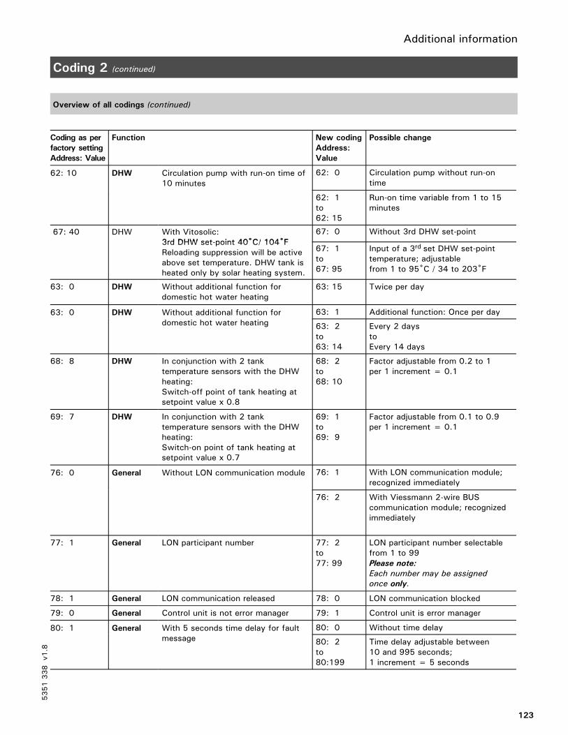
Additional information
123
Coding 2 (continued)
Overview of all codings (continued)
Coding as per
factory setting
Address: Value
Function New coding
Address:
Value
Possible change
62: 10 DHW Circulation pump with run-on time of10 minutes
62: 0 Circulation pump without run-ontime10 minutes
62: 1to62: 15
Run-on time variable from 1 to 15minutes
67: 40 DHW With Vitosolic:3rd DHW set-point 40˚C/ 104˚F
67: 0 Without 3rd DHW set-point3rd DHW set-point 40˚C/ 104˚FReloading suppression will be activeabove set temperature. DHW tank isheated only by solar heating system.
67: 1to67: 95
Input of a 3rd set DHW set-pointtemperature; adjustablefrom 1 to 95˚C / 34 to 203˚F
63: 0 DHW Without additional function fordomestic hot water heating
63: 15 Twice per day
63: 0 DHW Without additional function fordomestic hot water heating
63: 1 Additional function: Once per day63: 0 DHW Without additional function fordomestic hot water heating 63: 2
to63: 14
Every 2 daystoEvery 14 days
68: 8 DHW In conjunction with 2 tanktemperature sensors with the DHWheating:Switch-off point of tank heating atsetpoint value x 0.8
68: 2to68: 10
Factor adjustable from 0.2 to 1per 1 increment = 0.1
69: 7 DHW In conjunction with 2 tanktemperature sensors with the DHWheating:Switch-on point of tank heating atsetpoint value x 0.7
69: 1to69: 9
Factor adjustable from 0.1 to 0.9per 1 increment = 0.1
76: 0 General Without LON communication module 76: 1 With LON communication module;recognized immediately
76: 2 With Viessmann 2-wire BUScommunication module; recognizedimmediately
77: 1 General LON participant number 77: 2to77: 99
LON participant number selectablefrom 1 to 99Please note:
Each number may be assigned
once only.
78: 1 General LON communication released 78: 0 LON communication blocked
79: 0 General Control unit is not error manager 79: 1 Control unit is error manager
80: 1 General With 5 seconds time delay for faultmessage
80: 0 Without time delay80: 1 General With 5 seconds time delay for faultmessage 80: 2
to80:199
Time delay adjustable between10 and 995 seconds;1 increment = 5 seconds
5351338
v1.8

Additional information
124
Coding 2 (continued)
Overview of all codings (continued)
Coding as per
factory setting
Address: Value
Function New coding
Address:
Value
Possible change
88: 0 General Temperatures displayed in Celsius 88: 1 Temperatures displayed inFahrenheit
8A:175 General Display of codings which can be setfor the system type concerned
8A:176 All codings displayed regardless ofsystem type and equipmentinstalled
92:165 General Do not Adjust! Is only displayed if8A:176 is coded
93: 0 General Central fault indication in emissionstest mode/service display noteffective for central fault
93: 1 Central fault indication inemissions test mode/servicedisplay effective for central fault
94: 0 General Without plug-in adaptor for externalsafety equipment
94: 2 With plug-in adaptor for externalsafety equipment; recognizedautomatically
98: 1 General Viessmann system number(in conjunction with monitoring ofseveral systems within one LON BUSsystem)
98: 2to98: 5
System numberselectable from 1 to 5
9b: 0 General Input aVH released 9b: 1to9b:127
Set-point supply temperatureselectable via plug aVH from 1 to127°C / 261°F with externalrequest
9C: 20 General Monitoring of LON participants:If a participant does not answerback, default values set within the
9C: 0 No monitoringback, default values set within thecontrol unit are used for the first 20minutes. Then an error message istransmitted.
9C: 1to9C: 60
Time selectablefrom 1 to 60 minutes
9d: 0 General Without Input Module0 to 10V
9d: 1 With Input Module 0 - 10V;will be recognized automatically
5351338
v1.8

Additional information
125
Wiring Diagrams
Overview
A2 Low-voltage motherboardA3 Line voltage motherboardA6 Programming unitA7 Optolink/override switch boardA8 Electronics boardA9 Boiler coding cardA10 LON communication module or
Viessmann 2-wire BUScommunication module
A11 Power supply unit boardA12 Boiler control section
5351338
v1.8

Additional information
126
Wiring Diagrams (continued)
Low-voltage motherboard
5351338
v1.8
A11
A8
A9
A6
A7
A2
A10
34--pole
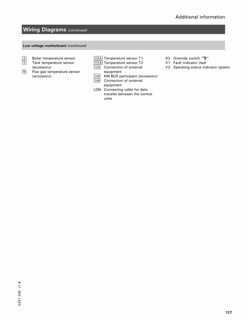
Additional information
127
Wiring Diagrams (continued)
Low-voltage motherboard (continued)
§ Boiler temperature sensor% Tank temperature sensor
(accessory)aG Flue gas temperature sensor
(accessory)
aJA Temperature sensor T1aJB Temperature sensor T2aVD Connection of external
equipmentaVG KM BUS participant (accessory)aVH Connection of external
equipmentLON Connecting cable for data
transfer between the controlunits
S3 Override switch ”S”V1 Fault indicator (red)V2 Operating status indicator (green)
5351338
v1.8

Additional information
128
Wiring Diagrams (continued)
Line voltage motherboard
5351338
v1.8
A11
A3
floating
ONON

Additional information
129
Wiring Diagrams (continued)
Line voltage motherboard (continued)
sÖ Control outputsA DHW pumpsL Shunt pump or boiler circuit pumpfÖ Power supply connection,
120 VACfA Burner connectiongÖ Compiled failure alarmgS Boiler isolation valve
orBoiler return valve
lÖ Burner (2nd stage/modulating)aBÖ External equipment
a External safety equipment(remove jumper whenconnecting)
b External controlled switch-off(remove jumper whenconnecting)
c External burner activationaBA Safety circuit - emergency
shut-offaBH Power supply connection for
accessories
F1, F2 FusesF6 Fixed high limit ”E”
120°C (99°C or 110°C) /248°F (210°C or 230°F)
F7 adjustable high limit ”R”95°C (100°C or 110°C)203°F (212°F or 230°F)
K1-K10 RelayS1 Heating system on/off
switch ”8”S2 TUV button
5351338
v1.8

Additional information
130
Parts List
GC1 SeriesOrder No. Serial No. *1
7134 553, 7134 554, 7511 361 7143003
7187096
7248247
Ordering Replacement Parts:
Please provide product Model andSerial Number from rating plate whenordering replacement parts. Orderreplacement parts from yourViessmann distributor.
Parts
001 Hinges002 Optic link004 Adjustable high limit knob005 Fixed high limit cover006 Dial-stop 110°C / 230°F008 Support arm011 Safety module (wired)013 Front housing (with Pos. 001)014 Circuit board enclosure015 Flip-down cover016 Rear housing018 Programming unit024 Fuse holder cover025 Fuse holder030 Fixed high limit031 Adjustable high limit037 Switch, 1-pole (FHL test)038 Switch, 2-pole (power on/off)042 Sensor #3 for boiler043 Sensor #5 for domestic hot
water production049 Motherboard
(control, low voltage)
050 Circuit board (control software)051 Diagnostics module (Optolink)052 Motherboard
(control, line voltage)054 Circuit board
(120V power supply)055 Communication module,
2-wire BUS056 LON module065 Burner cable Nr. 41/90 l=3470067 Sensor (immersion, NI500)068 Sensor #2 for supply074 Harness for programming unit092 Fuse 6.3A / 250V (10 pack)
Other Parts (not illustrated)060 Accessory pack (plugs)061 Coding plug for Vitocrossal 200062 Coding plug for Vitorond 200063 Coding plug for Vitocrossal 300;nnn080 Installation / Service Instructions
Vitotronic 100, GC1081 Operating Instructions
Vitotronic 100, GC1082 Parts List Vitotronic 100, GC1
Rating plate
*1 A 16-digit bar-coded serial no.
is printed on the front housing,
below the flip-down cover.
5351338
v1.8

Additional information
131
Parts List
5351338
v1.8

Viessmann Manufacturing Company Inc.750 McMurray RoadWaterloo, Ontario • N2V 2G5 • CanadaTel. (519) 885-6300 • Fax (519) 885-0887www.viessmann.ca • [email protected]
Viessmann Manufacturing Company (U.S.) Inc.45 Access RoadWarwick, Rhode Island • 02886 • USATel. (401) 732-0667 • Fax (401) 732-0590www.viessmann-us.com • [email protected]
Additional information
132
Quick Reference
°C °F
-40 -40
-35 -31
-25 -13
-20 -4
-18 0
-16 +3
-14 +7
-12 +10
-10 +14
-9 +16
-8 +18
-7 +19
-6 +21
-5 +23
-4 +25
-3 +27
-2 +28
-1 +30
0 +32
+1 +34
+2 +36
+3 +37
+4 +39
+5 +41
+6 +43
+7 +45
+8 +46
+9 +48
+10 +50
+12 +54
+14 +57
+16 +61
+18 +64
+20 +68
+25 +77
+30 +86
+35 +95
+40 +104
+50 +122
+60 +140
+70 +158
+80 +176
+90 +194
+100 +212
+110 +230
Printedonenvironmentally
friendly
(recycledandrecyclable)paper.
Technicalinformationsubjectto
changewithoutnotice.
5351338
v1.8