Embed Size (px)
Citation preview
VITODENS 200-W
Installation Instructionsfor use by heating contractor
Vitodens 200-W, WB2B Series
Models 45, 60
Wall-mounted, gas-fired condensing boiler
For operation with natural gas and liquid propane gasHeating input 60 to 212 MBH
17 to 62 kW
Read and save these instructions
for future reference.
IMPORTANT
This trademark is registered with the U.S. Patent and Trademark Office.
Ple
ase
file
inS
erv
ice
Bin
der
5418 909 v1.6 12/2011
Safety, Installation and Warranty Requirements
2
Safety, Installation and Warranty Requirements
Please ensure that these instructions are read and understood before commencing installation. Failure to comply with the
instructions listed below and details printed in this manual can cause product/property damage, severe personal injury, and/or loss
of life. Ensure all requirements below are understood and fulfilled (including detailed information found in manual subsections).
� Licensed professional heating
contractor
The installation, service, andmaintenance of this equipment mustbe performed by a licensedprofessional heating contractor.
� Please see section
entitled “Important
Regulatory and
Installation
Requirements” in the
Installation Instructions.
� Product documentation
Read all applicable documentation
before commencing installation. Storedocumentation near boiler in a readilyaccessible location for reference inthe future by service personnel.
� For a listing of
applicable literature,
please see section
entitled “Important
Regulatory and
Installation Requirements”
in the Installation Instructions.
�Advice to owner
Once the installation work iscomplete, the heating contractormust familiarize the systemoperator/ultimate owner with allequipment, as well as safetyprecautions/requirements, shut-downprocedure, and the need forprofessional service annually beforethe heating season begins.
�Carbon monoxide
Improper installation, service and/ormaintenance can cause flue productsto flow into living space. Flueproducts contain poisonous carbonmonoxide gas.
� For information
pertaining to the proper
installation, service and
maintenance of this
equipment to avoid
formation of carbon monoxide, please
see the Installation Instructions of the
Vitodens 200-W Venting System.
� Equipment venting
Never operate boiler without aninstalled venting system. An improperventing system can cause carbonmonoxide poisoning.
�Warranty
Information contained inthis and related productdocumentation must beread and followed. Failureto do so renders warranty
null and void.
5418909
v1.6
Installers must follow local
regulations with respect to
installation of carbon monoxide
detectors. Follow manufacturer’s
maintenance schedule of boiler.
WARNING
Table of Contents
3
Page
General Information Important Regulatory and Installation Requirements 5. . . . . . . . . . . . . . . . . . . . . . . . . . .
About these Installation Instructions 7. . . . . . . . . . . . . . . . . . . . . . . . . . . . . . . . . . . . . . . . . . . . . . . . . . . . . . . . . . .
Applicability 8. . . . . . . . . . . . . . . . . . . . . . . . . . . . . . . . . . . . . . . . . . . . . . . . . . . . . . . . . . . . . . . . . . . . . . . . . . . . . . . . . . . . . . . . . . . . . . . . . . . . . . . . . . .
Product Information 8. . . . . . . . . . . . . . . . . . . . . . . . . . . . . . . . . . . . . . . . . . . . . . . . . . . . . . . . . . . . . . . . . . . . . . . . . . . . . . . . . . . . . . . . . . .
Mechnical Room 9. . . . . . . . . . . . . . . . . . . . . . . . . . . . . . . . . . . . . . . . . . . . . . . . . . . . . . . . . . . . . . . . . . . . . . . . . . . . . . . . . . . . . . . . . . . . . . . . . .
Set-up Before Set-up 10. . . . . . . . . . . . . . . . . . . . . . . . . . . . . . . . . . . . . . . . . . . . . . . . . . . . . . . . . . . . . . . . . . . . . . . . . . . . . . . . . . . . . . . . . . . . . . . . . . . . . . . . .
Minimum Clearances 10. . . . . . . . . . . . . . . . . . . . . . . . . . . . . . . . . . . . . . . . . . . . . . . . . . . . . . . . . . . . . . . . . . . . . . . . . . . . . . . . . . . . . . . . . . .
Boiler Connections Preparing the Connections 11. . . . . . . . . . . . . . . . . . . . . . . . . . . . . . . . . . . . . . . . . . . . . . . . . . . . . . . . . . . . . . . . . . . . . . . . . . . . . .
Connections overview 11. . . . . . . . . . . . . . . . . . . . . . . . . . . . . . . . . . . . . . . . . . . . . . . . . . . . . . . . . . . . . . . . . . . . . . . . . . . . . . . . . . . . . . . .
Wall Mounting 13. . . . . . . . . . . . . . . . . . . . . . . . . . . . . . . . . . . . . . . . . . . . . . . . . . . . . . . . . . . . . . . . . . . . . . . . . . . . . . . . . . . . . . . . . . . . . . . . . . . . . .
Installing the wall mounting bracket 13. . . . . . . . . . . . . . . . . . . . . . . . . . . . . . . . . . . . . . . . . . . . . . . . . . . . . . . . . . .
Mounting the boiler 15. . . . . . . . . . . . . . . . . . . . . . . . . . . . . . . . . . . . . . . . . . . . . . . . . . . . . . . . . . . . . . . . . . . . . . . . . . . . . . . . . . . . . . . . . . . . .
Connections 16. . . . . . . . . . . . . . . . . . . . . . . . . . . . . . . . . . . . . . . . . . . . . . . . . . . . . . . . . . . . . . . . . . . . . . . . . . . . . . . . . . . . . . . . . . . . . . . . . . . . . . . . . . .
Connecting the power supply 16. . . . . . . . . . . . . . . . . . . . . . . . . . . . . . . . . . . . . . . . . . . . . . . . . . . . . . . . . . . . . . . . . . . . . . . . .
Boiler venting 16. . . . . . . . . . . . . . . . . . . . . . . . . . . . . . . . . . . . . . . . . . . . . . . . . . . . . . . . . . . . . . . . . . . . . . . . . . . . . . . . . . . . . . . . . . . . . . . . . . . . . . . .
Proper piping practice 16. . . . . . . . . . . . . . . . . . . . . . . . . . . . . . . . . . . . . . . . . . . . . . . . . . . . . . . . . . . . . . . . . . . . . . . . . . . . . . . . . . . . . . . . .
Gas shut-off valve connection 16. . . . . . . . . . . . . . . . . . . . . . . . . . . . . . . . . . . . . . . . . . . . . . . . . . . . . . . . . . . . . . . . . . . . . .
Gas connection and piping 17. . . . . . . . . . . . . . . . . . . . . . . . . . . . . . . . . . . . . . . . . . . . . . . . . . . . . . . . . . . . . . . . . . . . . . . . . . . . . .
Gas piping pressure test 18. . . . . . . . . . . . . . . . . . . . . . . . . . . . . . . . . . . . . . . . . . . . . . . . . . . . . . . . . . . . . . . . . . . . . . . . . . . . . . . . . . .
Heating water connections 19. . . . . . . . . . . . . . . . . . . . . . . . . . . . . . . . . . . . . . . . . . . . . . . . . . . . . . . . . . . . . . . . . . . . . . . . . . . . .
DHW storage tank information 20. . . . . . . . . . . . . . . . . . . . . . . . . . . . . . . . . . . . . . . . . . . . . . . . . . . . . . . . . . . . . . . . . . . . . . .
Making the DHW connections 20. . . . . . . . . . . . . . . . . . . . . . . . . . . . . . . . . . . . . . . . . . . . . . . . . . . . . . . . . . . . . . . . . . . . . . . .
Accessing the control unit cables 22. . . . . . . . . . . . . . . . . . . . . . . . . . . . . . . . . . . . . . . . . . . . . . . . . . . . . . . . . . . . . . . .
Connecting DHW sensor 23. . . . . . . . . . . . . . . . . . . . . . . . . . . . . . . . . . . . . . . . . . . . . . . . . . . . . . . . . . . . . . . . . . . . . . . . . . . . . . . . . . .
High altitudes setting 23. . . . . . . . . . . . . . . . . . . . . . . . . . . . . . . . . . . . . . . . . . . . . . . . . . . . . . . . . . . . . . . . . . . . . . . . . . . . . . . . . . . . . . . . .
Condensate connection 24. . . . . . . . . . . . . . . . . . . . . . . . . . . . . . . . . . . . . . . . . . . . . . . . . . . . . . . . . . . . . . . . . . . . . . . . . . . . . . . . . . . . .
Safety Connections and Pressure Testing 25. . . . . . . . . . . . . . . . . . . . . . . . . . . . . . . . . . . . . . . . . . . . . . . . .
Installing boiler safety devices 25. . . . . . . . . . . . . . . . . . . . . . . . . . . . . . . . . . . . . . . . . . . . . . . . . . . . . . . . . . . . . . . . . . . . . .
Performing boiler pressure test 26. . . . . . . . . . . . . . . . . . . . . . . . . . . . . . . . . . . . . . . . . . . . . . . . . . . . . . . . . . . . . . . . . . . . . .
Installation Examples 27. . . . . . . . . . . . . . . . . . . . . . . . . . . . . . . . . . . . . . . . . . . . . . . . . . . . . . . . . . . . . . . . . . . . . . . . . . . . . . . . . . . . . . . . .
Waterside flow (primary circuit) 28. . . . . . . . . . . . . . . . . . . . . . . . . . . . . . . . . . . . . . . . . . . . . . . . . . . . . . . . . . . . . . . . . . . .
System layout 1 29. . . . . . . . . . . . . . . . . . . . . . . . . . . . . . . . . . . . . . . . . . . . . . . . . . . . . . . . . . . . . . . . . . . . . . . . . . . . . . . . . . . . . . . . . . . . . . . . . . .
System layout 2 30. . . . . . . . . . . . . . . . . . . . . . . . . . . . . . . . . . . . . . . . . . . . . . . . . . . . . . . . . . . . . . . . . . . . . . . . . . . . . . . . . . . . . . . . . . . . . . . . . . .
System layout 3 31. . . . . . . . . . . . . . . . . . . . . . . . . . . . . . . . . . . . . . . . . . . . . . . . . . . . . . . . . . . . . . . . . . . . . . . . . . . . . . . . . . . . . . . . . . . . . . . . . . .
System layout 4 32. . . . . . . . . . . . . . . . . . . . . . . . . . . . . . . . . . . . . . . . . . . . . . . . . . . . . . . . . . . . . . . . . . . . . . . . . . . . . . . . . . . . . . . . . . . . . . . . . . .
System layout 5 33. . . . . . . . . . . . . . . . . . . . . . . . . . . . . . . . . . . . . . . . . . . . . . . . . . . . . . . . . . . . . . . . . . . . . . . . . . . . . . . . . . . . . . . . . . . . . . . . . . .
System layout 6 34. . . . . . . . . . . . . . . . . . . . . . . . . . . . . . . . . . . . . . . . . . . . . . . . . . . . . . . . . . . . . . . . . . . . . . . . . . . . . . . . . . . . . . . . . . . . . . . . . . .
System layout 7 35. . . . . . . . . . . . . . . . . . . . . . . . . . . . . . . . . . . . . . . . . . . . . . . . . . . . . . . . . . . . . . . . . . . . . . . . . . . . . . . . . . . . . . . . . . . . . . . . . . .
System layout 8 36. . . . . . . . . . . . . . . . . . . . . . . . . . . . . . . . . . . . . . . . . . . . . . . . . . . . . . . . . . . . . . . . . . . . . . . . . . . . . . . . . . . . . . . . . . . . . . . . . . .
System layout 9 37. . . . . . . . . . . . . . . . . . . . . . . . . . . . . . . . . . . . . . . . . . . . . . . . . . . . . . . . . . . . . . . . . . . . . . . . . . . . . . . . . . . . . . . . . . . . . . . . . . .
Vitodens 200-W, WB2B (alternate DHW connection) 38. . . . . . . . . . . . . . . . . . . . . . . . .
Boiler in heating/cooling application 39. . . . . . . . . . . . . . . . . . . . . . . . . . . . . . . . . . . . . . . . . . . . . . . . . . . . . . . . . . . . .
Boiler with low water cut-off (remote-mounted, field supplied) 40. . . . . .
Venting Connection 40. . . . . . . . . . . . . . . . . . . . . . . . . . . . . . . . . . . . . . . . . . . . . . . . . . . . . . . . . . . . . . . . . . . . . . . . . . . . . . . . . . . . . . . . . . . .
5418909v1.6
Table of Contents
4
Control Connections Electrical Connections 41. . . . . . . . . . . . . . . . . . . . . . . . . . . . . . . . . . . . . . . . . . . . . . . . . . . . . . . . . . . . . . . . . . . . . . . . . . . . . . . . . . . . . . .
Overview of electrical connections and plug-in connectors 41. . . . . . . . . . . . .
Connecting the Power/Pump module 41. . . . . . . . . . . . . . . . . . . . . . . . . . . . . . . . . . . . . . . . . . . . . . . . . . . . . . . . .
Power/Pump module electrical connectors 43. . . . . . . . . . . . . . . . . . . . . . . . . . . . . . . . . . . . . . . . . . . . . .
Boiler control board GC 130 electrical connectors 44. . . . . . . . . . . . . . . . . . . . . . . . . . . . . . .
Connection between the Power/Pump module and boiler 45. . . . . . . . . . . . . . . . .
Accessories electrical connections 46. . . . . . . . . . . . . . . . . . . . . . . . . . . . . . . . . . . . . . . . . . . . . . . . . . . . . . . . . . . . . .
Accessing the X3 plug 47. . . . . . . . . . . . . . . . . . . . . . . . . . . . . . . . . . . . . . . . . . . . . . . . . . . . . . . . . . . . . . . . . . . . . . . . . . . . . . . . . . . . .
Connecting the low-loss header sensor 47. . . . . . . . . . . . . . . . . . . . . . . . . . . . . . . . . . . . . . . . . . . . . . . . . . . . .
Connecting the outdoor temperature sensor 48. . . . . . . . . . . . . . . . . . . . . . . . . . . . . . . . . . . . . . . . . .
External switching of heating program/External heat demand/External blocking 49. . . . . . . . . . . . . . . . . . . . . . . . . . . . . . . . . . . . . . . . . . . . . . . . . . . . . . . . . . . . . . . . . . . . . . . . . . . . . . . . . . . . . . . . . . . . . . . . . .
External 0-10 volt signal connection 49. . . . . . . . . . . . . . . . . . . . . . . . . . . . . . . . . . . . . . . . . . . . . . . . . . . . . . . . . . .
Connecting the LON communication module 50. . . . . . . . . . . . . . . . . . . . . . . . . . . . . . . . . . . . . . . . .
Accessory kit connections for heating circuit with mixing valvepart no. 7133392 (old version) 52. . . . . . . . . . . . . . . . . . . . . . . . . . . . . . . . . . . . . . . . . . . . . . . . . . . . . . . . . . . . . . . . . . . . .
Accessory kit connections for heating circuit with mixing valvepart no. 7837524 (new version) 53. . . . . . . . . . . . . . . . . . . . . . . . . . . . . . . . . . . . . . . . . . . . . . . . . . . . . . . . . . . . . . . . . . .
Wiring diagram for the boiler / Power/Pump module 54. . . . . . . . . . . . . . . . . . . . . . . . . . . .
Installing the Programming Unit of the Control Unit 55. . . . . . . . . . . . . . . . . . . . . . . . . . . .
Closing the control unit and inserting the programming unit 55. . . . . . . . . . .
Reinstalling the front enclosure panel 55. . . . . . . . . . . . . . . . . . . . . . . . . . . . . . . . . . . . . . . . . . . . . . . . . . . . . . . . .
Additional Information Technical Data 56. . . . . . . . . . . . . . . . . . . . . . . . . . . . . . . . . . . . . . . . . . . . . . . . . . . . . . . . . . . . . . . . . . . . . . . . . . . . . . . . . . . . . . . . . . . . . . . . . . . . . .
Wiring Diagram 58. . . . . . . . . . . . . . . . . . . . . . . . . . . . . . . . . . . . . . . . . . . . . . . . . . . . . . . . . . . . . . . . . . . . . . . . . . . . . . . . . . . . . . . . . . . . . . . . . . . . . .
Complete system wiring diagram 58. . . . . . . . . . . . . . . . . . . . . . . . . . . . . . . . . . . . . . . . . . . . . . . . . . . . . . . . . . . . . . . . . .
Lighting and Operating Instructions 60. . . . . . . . . . . . . . . . . . . . . . . . . . . . . . . . . . . . . . . . . . . . . . . . . . . . . . . . . . . .
Ladder Diagram 61. . . . . . . . . . . . . . . . . . . . . . . . . . . . . . . . . . . . . . . . . . . . . . . . . . . . . . . . . . . . . . . . . . . . . . . . . . . . . . . . . . . . . . . . . . . . . . . . . . . .
5418909
v1.6
General Information
5
Important Regulatory and Installation Requirements
Codes
The installation of this unit shall be inaccordance with local codes or, in theabsence of local codes, useCAN/CSA-B149.1 or .2 InstallationCodes for Gas Burning Appliances forCanada. For U.S. installations use theNational Fuel Gas Code ANSI Z223.1.Always use latest editions of codes.
In Canada all electrical wiring is to bedone in accordance with the latestedition of CSA C22.1 Part 1 and/orlocal codes. In the U.S. use theNational Electrical Code ANSI/NFPA70. The heating contractor must alsocomply with both the Standard forControls and Safety Devices forAutomatically Fired Boilers,ANSI/ASME CSD-1, and the InstallationCode for Hydronic Heating Systems,CSA B214-01, where required by theauthority having jurisdiction.
Instructing the system user
The installer of the system isresponsible to ensure the systemoperator/ultimate owner is madefamiliar with the system functioning,its activation, and its shut-down.
Initial start-up
Initial start-up must be performed by aqualified heating contractor. Propercompletion of the Maintenance Recordby the heating contractor is alsorequired.
Working on the equipment
The installation, adjustment, service,and maintenance of this boiler must bedone by a licensed professional heatingcontractor who is qualified andexperienced in the installation, service,and maintenance of hot water boilers.There are no user serviceable parts on
the boiler, burners, or control.
The following topics must be
covered:
Proper system operation sequence.
Explain the equipment.
Demonstrate an emergency
shut-down, what to do and what not.
Explain that there is no substitute for
proper maintenance to help ensure
safe operation.
The Maintenance Record is located in
the Start-up and Service Instructions.
Please carefully read this manual prior
to attempting start-up, maintenance
or service. Any warranty is null and
void if these instructions are not
followed.
For information regarding other
Viessmann System Technology
componentry, please reference
documentation of the respective
product.
We offer frequent installation and
service seminars to familiarize our
partners with our products. Please
inquire.
Ensure main power supply toequipment, the heating system, and allexternal controls has been deactivated.Close main gas supply valve. Takeprecautions in all instances to avoidaccidental activation of power duringservice work.
The completeness and functionality of
field supplied electrical controls and
components must be verified by the
heating contractor. These include low
water cut-offs, flow switches (if used),
staging controls, pumps, motorized
valves, air vents, thermostats, etc.
Technical literature
Literature for the Vitodens boiler:- Technical Data Manual- Installation Instructions- Start-up/Service Instructions- Operating Instructionsand User’s Information Manual
- Instructions of other Viessmannproducts utilized and installed
- Installation codes mentionedin this manual
Leave all literature at the installation
site and advise the system
operator/ultimate owner where the
literature can be found. Contact
Viessmann for additional copies.
This product comes with several
safety instruction labels attached.
Do not remove!
Contact Viessmann immediately if
replacement labels are required.
5418909
v1.6
General Information
6
Important Regulatory and Installation Requirements (continued)
For installations on the Commonwealth of Massachusetts, the following modifications to NFPA-54 chapter 10 apply:
Excerpt from 248 CMR 5-08:
2(a) For all side-wall horizontally vented gas fueled equipment installed in every dwelling, building or structure used inwhole or in part for residential purposes, including those owned or operated by the Commonwealth and where theside-wall exhaust vent termination is less than (7) feet above finished grade in the area of the venting, including butnot limited to decks and porches, the following requirements shall be satisfied:
1. INSTALLATION OF CARBON MONOXIDE DETECTORS. At the time of installation of the side-wall horizontalvented gas fueled equipment, the installing plumber or gasfitter shall observe that a hard wired carbon monoxidedetector with an alarm and battery back-up is installed on the floor level where the gas equipment is to beinstalled. In addition, the installing plumber or gasfitter shall observe that a battery operated or hard wired carbonmonoxide detector with an alarm is installed on each additional level of the dwelling, building or structure servedby the side-wall horizontal vented gas fueled equipment. It shall be the responsibility of the property owner tosecure the services of qualified licensed professional for the installation of hard-wired carbon monoxide detectors.
a. In the event that the side-wall horizontally vented gas fueled equipment is installed in a crawl space or an attic,the hard-wired carbon monoxide detector with alarm and battery back-up may be installed on the next adjacentfloor level.
b. In the event that the requirements of this subdivision can not be met at the time of completion of installation, theowner shall have a period of thirty (30) days to comply with the above requirements; provided, however, thatduring said thirty (30) day period, a battery operated carbon monoxide detector with an alarm shall be installed.
2. APPROVED CARBON MONOXIDE DETECTORS. Each carbon monoxide detector as required in accordance withthe above provisions shall comply with NFPA 720 and be ANSI/UL 2034 listed and IAS certified.
3. SIGNAGE. A metal or plastic identification plate shall be permanently mounted to the exterior of the building at aminimum height of eight (8) feet above grade directly in line with the exhaust vent terminal for the horizontallyvented gas fueled heating appliance or equipment. The sign shall read, in print size no less than one-half (1/2) inchin size, ”GAS VENT DIRECTLY BELOW. KEEP CLEAR OF ALL OBSTRUCTIONS”.
4. INSPECTION. The state or local gas inspector of the side-wall horizontally vented gas fueled equipment shall notapprove the installation unless, upon inspection, the inspector observes carbon monoxide detectors and signageinstalled in accordance with the provisions of 248 CMR 5.08(2)(a) 1 through 4.
(b) EXEMPTIONS: The following equipment is exempt from 248 CMR 5.08(2)(a) 1 through 4:
1. The equipment listed in Chapter 10 entitled ”Equipment Not Required To Be Vented” in the most current edition ofNFPA 54 as adopted by the Board; and
2. Product Approved side-wall horizontally vented gas fueled equipment installed in a room or structure separatefrom the dwelling, building or structure used in whole or in part for residential purposes.
5418909
v1.6
General Information
7
About these Installation Instructions
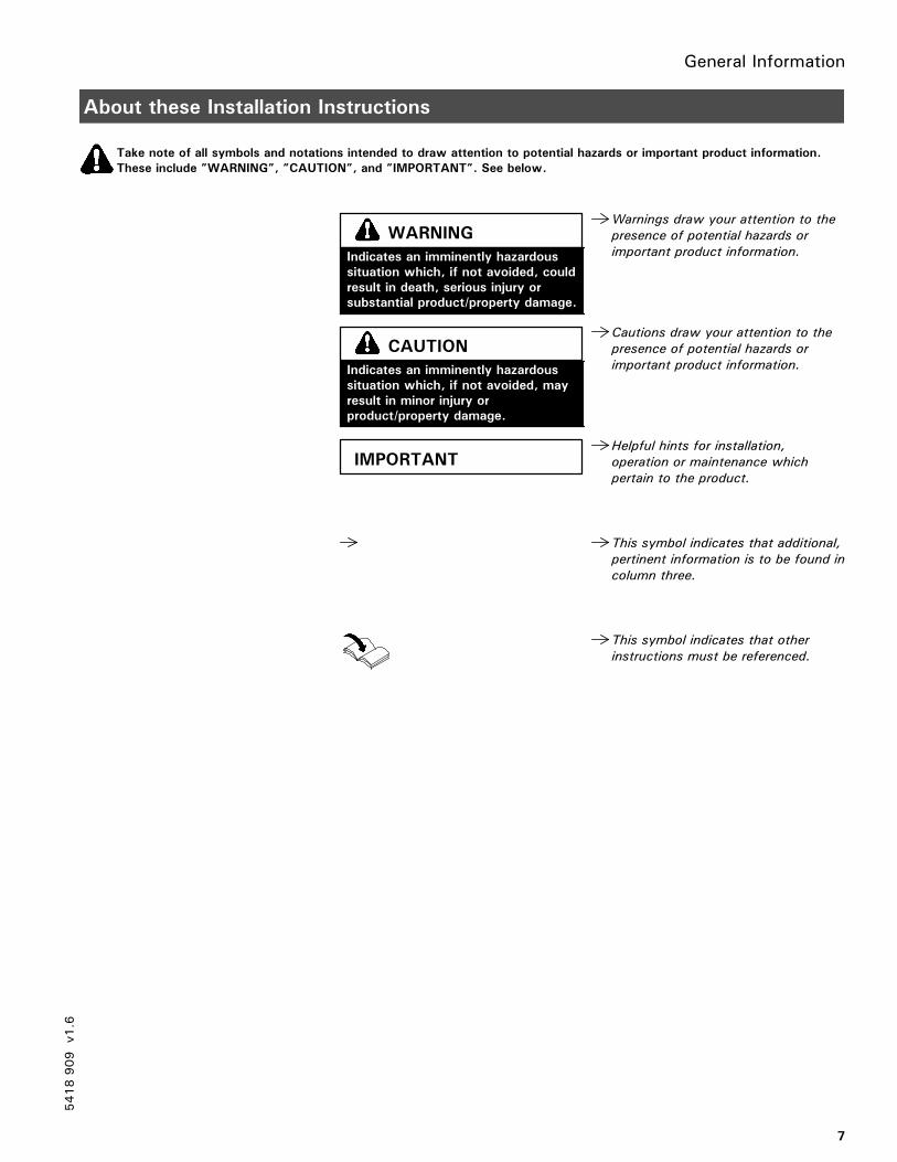
Take note of all symbols and notations intended to draw attention to potential hazards or important product information.
These include ”WARNING”, ”CAUTION”, and ”IMPORTANT”. See below.
Warnings draw your attention to the
presence of potential hazards or
important product information.
Cautions draw your attention to the
presence of potential hazards or
important product information.
Helpful hints for installation,
operation or maintenance which
pertain to the product.
This symbol indicates that additional,
pertinent information is to be found in
column three.
This symbol indicates that other
instructions must be referenced.
5418909
v1.6
Indicates an imminently hazardous
situation which, if not avoided, could
result in death, serious injury or
substantial product/property damage.
WARNING
Indicates an imminently hazardous
situation which, if not avoided, may
result in minor injury or
product/property damage.
CAUTION
IMPORTANT
General InformationGeneral Information
8
Applicability
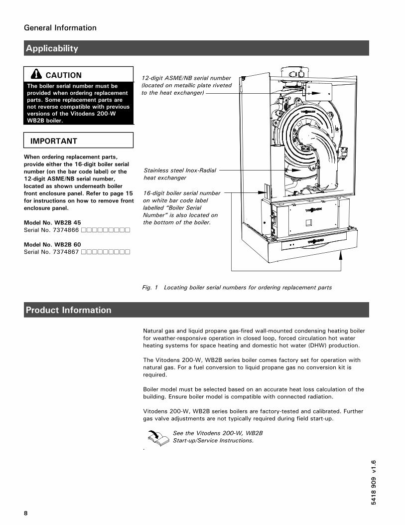
When ordering replacement parts,
provide either the 16-digit boiler serial
number (on the bar code label) or the
12-digit ASME/NB serial number,
located as shown underneath boiler
front enclosure panel. Refer to page 15
for instructions on how to remove front
enclosure panel.
Model No. WB2B 45
Serial No. 7374866 ���������
Model No. WB2B 60
Serial No. 7374867 ���������
Product Information
Natural gas and liquid propane gas-fired wall-mounted condensing heating boilerfor weather-responsive operation in closed loop, forced circulation hot waterheating systems for space heating and domestic hot water (DHW) production.
The Vitodens 200-W, WB2B series boiler comes factory set for operation withnatural gas. For a fuel conversion to liquid propane gas no conversion kit isrequired.
Boiler model must be selected based on an accurate heat loss calculation of thebuilding. Ensure boiler model is compatible with connected radiation.
Vitodens 200-W, WB2B series boilers are factory-tested and calibrated. Furthergas valve adjustments are not typically required during field start-up.
See the Vitodens 200-W, WB2B
Start-up/Service Instructions.
.
5418909
v1.6
The boiler serial number must be
provided when ordering replacement
parts. Some replacement parts are
not reverse compatible with previous
versions of the Vitodens 200-W
WB2B boiler.
CAUTION
IMPORTANT
Fig. 1 Locating boiler serial numbers for ordering replacement parts
12-digit ASME/NB serial number
(located on metallic plate riveted
to the heat exchanger)
16-digit boiler serial number
on white bar code label
labelled “Boiler Serial
Number” is also located on
the bottom of the boiler.
Stainless steel Inox-Radial
heat exchanger
5418909
v1.6
General Information
9
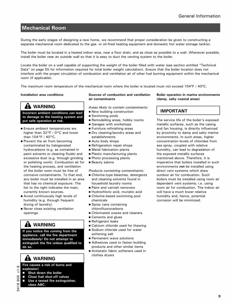
Mechanical Room
During the early stages of designing a new home, we recommend that proper consideration be given to constructing aseparate mechanical room dedicated to the gas- or oil-fired heating equipment and domestic hot water storage tank(s).
The boiler must be located in a heated indoor area, near a floor drain, and as close as possible to a wall. Whenever possible,install the boiler near an outside wall so that it is easy to duct the venting system to the boiler.
Locate the boiler on a wall capable of supporting the weight of the boiler filled with water (see section entitled “TechnicalData” on page 55 for information required for total boiler weight calculation). Ensure that the boiler location does notinterfere with the proper circulation of combustion and ventilation air of other fuel burning equipment within the mechanicalroom (if applicable).
The maximum room temperature of the mechanical room where the boiler is located must not exceed 104ºF / 40ºC.
Installation area conditions
� Ensure ambient temperatures arehigher than 32°F / 0°C and lowerthan 104°F / 40°C.
� Prevent the air from becomingcontaminated by halogenatedhydrocarbons (e.g. as contained inpaint solvents or cleaning fluids) andexcessive dust (e.g. through grindingor polishing work). Combustion air forthe heating process, and ventilationof the boiler room must be free ofcorrosive contaminants. To that end,any boiler must be installed in an areathat has no chemical exposure. Thelist to the right indicates the main,currently known sources.
� Avoid continuously high levels ofhumidity (e.g. through frequentdrying of laundry).
� Never close existing ventilationopenings.
Sources of combustion and ventilation
air contaminants
Areas likely to contain contaminants:
� New building construction� Swimming pools� Remodelling areas, hobby rooms� Garages with workshops� Furniture refinishing areas� Dry cleaning/laundry areas andestablishments
� Auto body shops� Refrigeration repair shops� Metal fabrication plants� Plastic manufacturing plants� Photo processing plants� Beauty salons
Products containing contaminants:
� Chlorine-type bleaches, detergentsand cleaning solvents found inhousehold laundry rooms
� Paint and varnish removers� Hydrochloric acid, muriatic acid� Chlorine-based swimming poolchemicals
� Spray cans containingchlorofluorocarbons
� Chlorinated waxes and cleaners� Cements and glues� Refrigerant leaks� Calcium chloride used for thawing� Sodium chloride used for watersoftening salt
� Permanent wave solutions� Adhesives used to fasten buildingproducts and other similar items
� Antistatic fabric softeners used inclothes dryers
Boiler operation in marine environments
(damp, salty coastal areas)
The service life of the boiler’s exposedmetallic surfaces, such as the casingand fan housing, is directly influencedby proximity to damp and salty marineenvironments. In such areas, higherconcentration levels of chlorides fromsea spray, coupled with relativehumidity, can lead to degradation ofthe exposed metallic surfacesmentioned above. Therefore, it isimperative that boilers installed in suchenvironments not be installed usingdirect vent systems which drawoutdoor air for combustion. Suchboilers must be installed using room airdependent vent systems; i.e. usingroom air for combustion. The indoor airwill have a much lower relativehumidity and, hence, potentialcorrosion will be minimized.
5418909
v1.6
Incorrect ambient conditions can lead
to damage to the heating system and
put safe operation at risk.
WARNING
If you notice fire coming from the
appliance, call the fire department
immediately! Do not attempt to
extinguish the fire unless qualified to
do so.
WARNING
Fire causes a risk of burns and
explosion!
���� Shut down the boiler
���� Close fuel shut-off valves
���� Use a tested fire extinguisher,
class ABC.
WARNING
IMPORTANT
Set-up
10
Before Set-up
Before placing boiler in its installationlocation, ensure all necessaryaccessories are installed.
Minimum Clearances
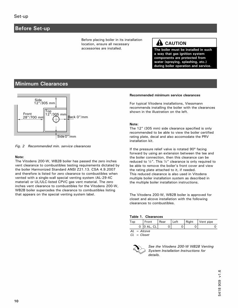
Recommended minimum service clearances
For typical Vitodens installations, Viessmannrecommends installing the boiler with the clearancesshown in the illustration on the left.
Note:
The 12” (305 mm) side clearance specified is onlyrecommended to be able to view the boiler certifiedrating plate, decal and also accomodate the PRVinstallation kit.
If the pressure relief valve is rotated 90º facingforward by using an extension between the tee andthe boiler connection, then this clearance can bereduced to b”. This b” clearance is only required tobe able to remove the boiler’s front cover and viewthe rating plate attached to it, if needed.This reduced clearance is also used in Vitodensmultiple boiler installation system as described inthe multiple boiler installation instructions.
The Vitodens 200-W, WB2B boiler is approved forcloset and alcove installation with the followingclearances to combustibles.
Table 1. Clearances
Top Front Rear Left Right Vent pipe
0 0 AL, CL 0 0 0 0
AL = Alcove
CL = Closet
See the Vitodens 200-W WB2B Venting
System Installation Instructions for
details.
5418909
v1.6
The boiler must be installed in such
a way that gas ignition system
components are protected from
water (spraying, splashing, etc.)
during boiler operation and service.
CAUTION
Front
12”/305 mm
12”/305 mm
0”/mm
28”/700 mm
Side
0”/mmBack
Side
Fig. 2 Recommended min. service clearances
Top
Note:
The Vitodens 200-W, WB2B boiler has passed the zero inchesvent clearance to combustibles testing requirements dictated bythe boiler Harmonized Standard ANSI Z21.13. CSA 4.9.2007and therefore is listed for zero clearance to combustibles whenvented with a single-wall special venting system (AL-29-4Cmaterial) or UL/ULC-listed CPVC gas vent material. The zeroinches vent clearance to combustibles for the Vitodens 200-W,WB2B boiler supercedes the clearance to combustibles listingthat appears on the special venting system label.
Boiler Connections
11
Preparing the Connections
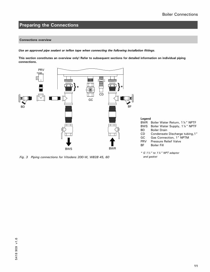
Connections overview
Use an approved pipe sealant or teflon tape when connecting the following installation fittings.
This section constitutes an overview only! Refer to subsequent sections for detailed information on individual piping
connections.
Legend
BWR Boiler Water Return, 1¼” NPTFBWS Boiler Water Supply, 1¼” NPTFBD Boiler DrainCD Condensate Discharge tubing,1”GC Gas Connection, 1” NPTMPRV Pressure Relief ValveBF Boiler Fill
* G 1½” to 1¼” NPT adaptor
and gasket
5418909
v1.6
BWS BWR
CD
PRV
BD
} }* *
GC
BF
Fig. 3 Piping connections for Vitodens 200-W, WB2B 45, 60
Boiler Connections
12
Preparing the Connections (continued)
Connections overview (continued)
Use an approved pipe sealant or teflon tape when connecting the following installation fittings.
This section constitutes an overview only! Refer to subsequent sections for detailed information on individual piping
connections.
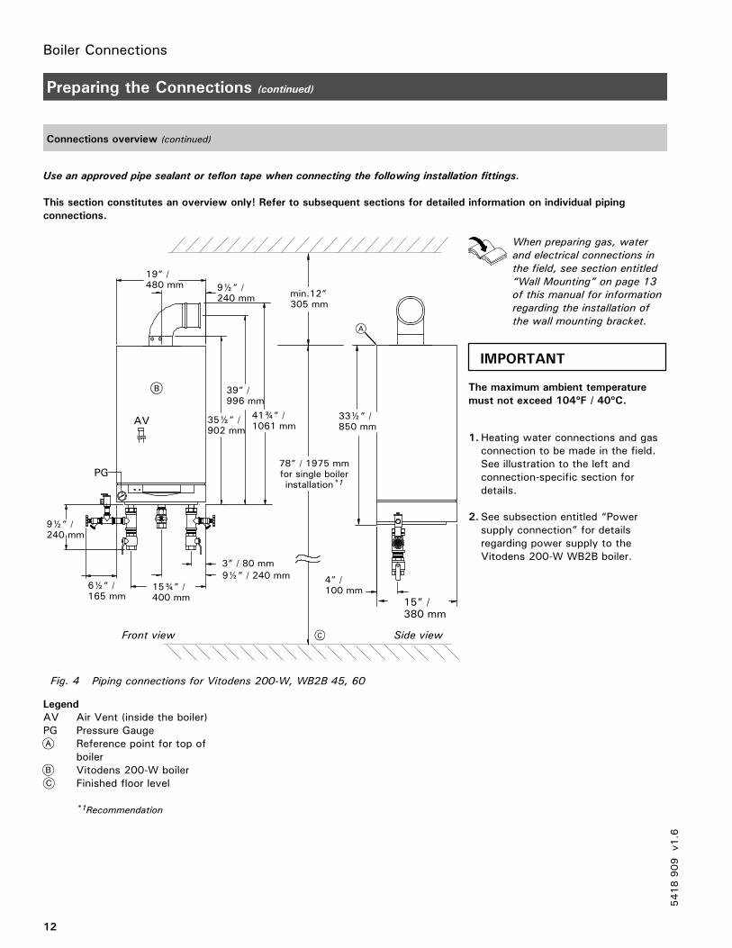
Legend
AV Air Vent (inside the boiler)PG Pressure Gauge
Reference point for top ofboilerVitodens 200-W boilerFinished floor level
*1Recommendation
When preparing gas, water
and electrical connections in
the field, see section entitled
“Wall Mounting” on page 13
of this manual for information
regarding the installation of
the wall mounting bracket.
The maximum ambient temperature
must not exceed 104ºF / 40ºC.
1.Heating water connections and gasconnection to be made in the field.See illustration to the left andconnection-specific section fordetails.
2. See subsection entitled “Powersupply connection” for detailsregarding power supply to theVitodens 200-W WB2B boiler.
5418909
v1.6
78” / 1975 mmfor single boilerinstallation*1
4” /100 mm
15” /380 mm
33½” /850 mm
Fig. 4 Piping connections for Vitodens 200-W, WB2B 45, 60
Front view Side view
min.12”305 mm
19” /480 mm 9½” /
240 mm
35½” /902 mm
39” /996 mm
41¾” /1061 mm
6½” /165 mm
9½” / 240 mm3” / 80 mm
15¾” /400 mm
PG
9½” /240 mm
AV
IMPORTANT
Boiler Connections
13
Wall Mounting
Installing the wall mounting bracket
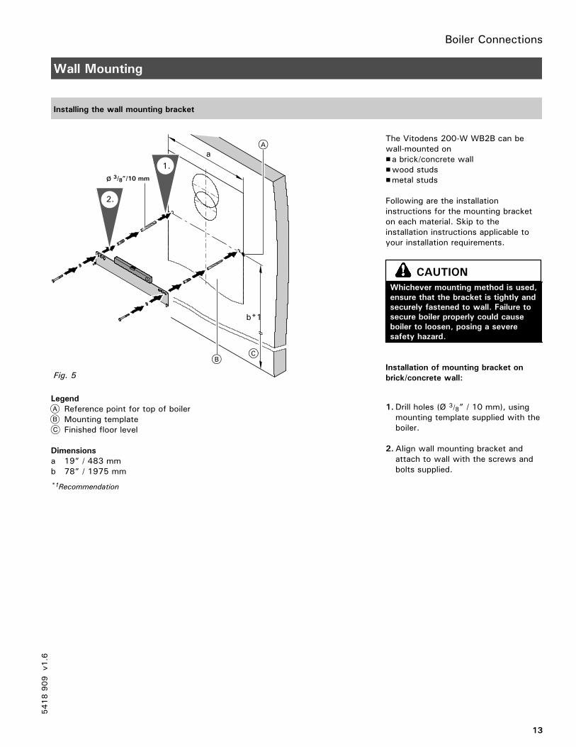
Legend
Reference point for top of boilerMounting templateFinished floor level
Dimensions
a 19” / 483 mmb 78” / 1975 mm
*1Recommendation
The Vitodens 200-W WB2B can bewall-mounted on�a brick/concrete wall�wood studs�metal studs
Following are the installationinstructions for the mounting bracketon each material. Skip to theinstallation instructions applicable toyour installation requirements.
Installation of mounting bracket on
brick/concrete wall:
1.Drill holes (Ø 3/8” / 10 mm), usingmounting template supplied with theboiler.
2.Align wall mounting bracket andattach to wall with the screws andbolts supplied.
5418909
v1.6
a
b*1
3/8”/10 mm
2.
1.
Fig. 5
Whichever mounting method is used,
ensure that the bracket is tightly and
securely fastened to wall. Failure to
secure boiler properly could cause
boiler to loosen, posing a severe
safety hazard.
CAUTION
Boiler Connections
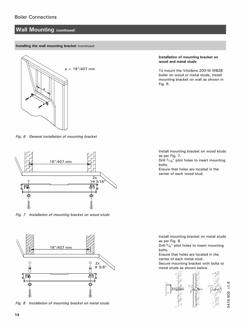
Fig. 6 General installation of mounting bracket
a
a = 16”/407 mm
Fig. 7 Installation of mounting bracket on wood studs
16”/407 mm
3/16”2x
Fig. 8 Installation of mounting bracket on metal studs
5/8”2x
16”/407 mm
14
Wall Mounting (continued)
Installing the wall mounting bracket (continued)
Installation of mounting bracket on
wood and metal studs
To mount the Vitodens 200-W WB2Bboiler on wood or metal studs, installmounting bracket on wall as shown inFig. 6.
Install mounting bracket on wood studsas per Fig. 7.Drill 3/16” pilot holes to insert mountingbolts.Ensure that holes are located in thecenter of each wood stud.
Install mounting bracket on metal studsas per Fig. 8.Drill 5/8” pilot holes to insert mountingbolts.Ensure that holes are located in thecenter of each metal stud.Secure mounting bracket with bolts tometal studs as shown below.
5418909
v1.6
Boiler Connections
15
Wall Mounting (continued)
Mounting the boiler
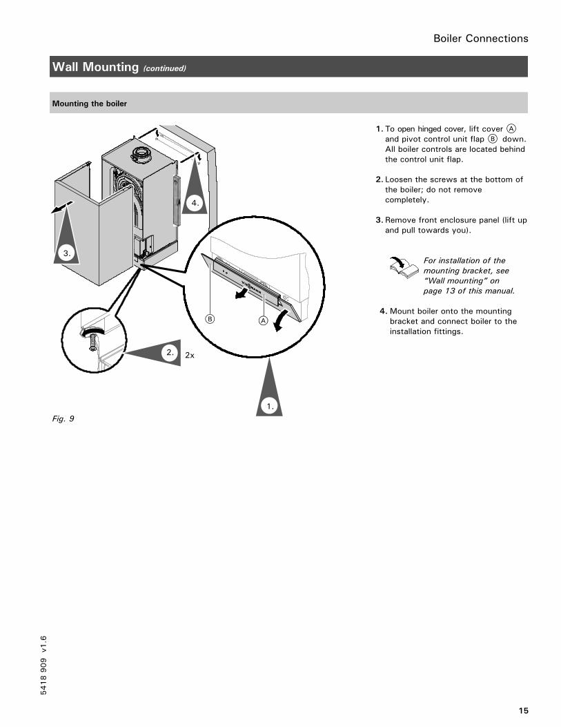
1. To open hinged cover, lift cover Aand pivot control unit flap B down.All boiler controls are located behindthe control unit flap.
2. Loosen the screws at the bottom ofthe boiler; do not removecompletely.
3. Remove front enclosure panel (lift upand pull towards you).
For installation of the
mounting bracket, see
“Wall mounting” on
page 13 of this manual.
4.Mount boiler onto the mountingbracket and connect boiler to theinstallation fittings.
5418909
v1.6
2x
4.
3.
2.
Fig. 9
1.
Boiler Connections
16
Connections
Connecting the power supply
See Power/Pump
Module Installation
Instructions
The Vitodens 200-W boiler is shippedwith a Power/Pump module, whichrequires a 120 VAC power supplyfrom a wall receptacle. The modulecontains a 120/230 VAC step-uptransformer for 230 VAC operation.
Refer to the Installation Instructionsshipped with the module or thosecontained in this manual for wiringdetails (see page 53).
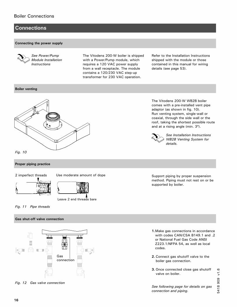
Boiler venting
The Vitodens 200-W WB2B boilercomes with a pre-installed vent pipeadaptor (as shown in fig. 10).Run venting system, single-wall orcoaxial, through the side wall or theroof, taking the shortest possible routeand at a rising angle (min. 3º).
See Installation Instructions
WB2B Venting System for
details.
Proper piping practice
Support piping by proper suspensionmethod. Piping must not rest on or besupported by boiler.
Gas shut-off valve connection
1.Make gas connections in accordancewith codes CAN/CSA B149.1 and .2or National Fuel Gas Code ANSIZ223.1/NFPA 54, as well as localcodes.
2.Connect gas shutoff valve to theboiler gas connection.
3.Once connected close gas shutoffvalve on boiler.
See following page for details on gas
connection and piping. 5418909
v1.6
Fig. 10
Use moderate amount of dope
Leave 2 end threads bare
2 imperfect threads
Fig. 11 Pipe threads
Fig. 12 Gas valve connection
Gasconnection
Boiler Connections
17
Connections (continued)
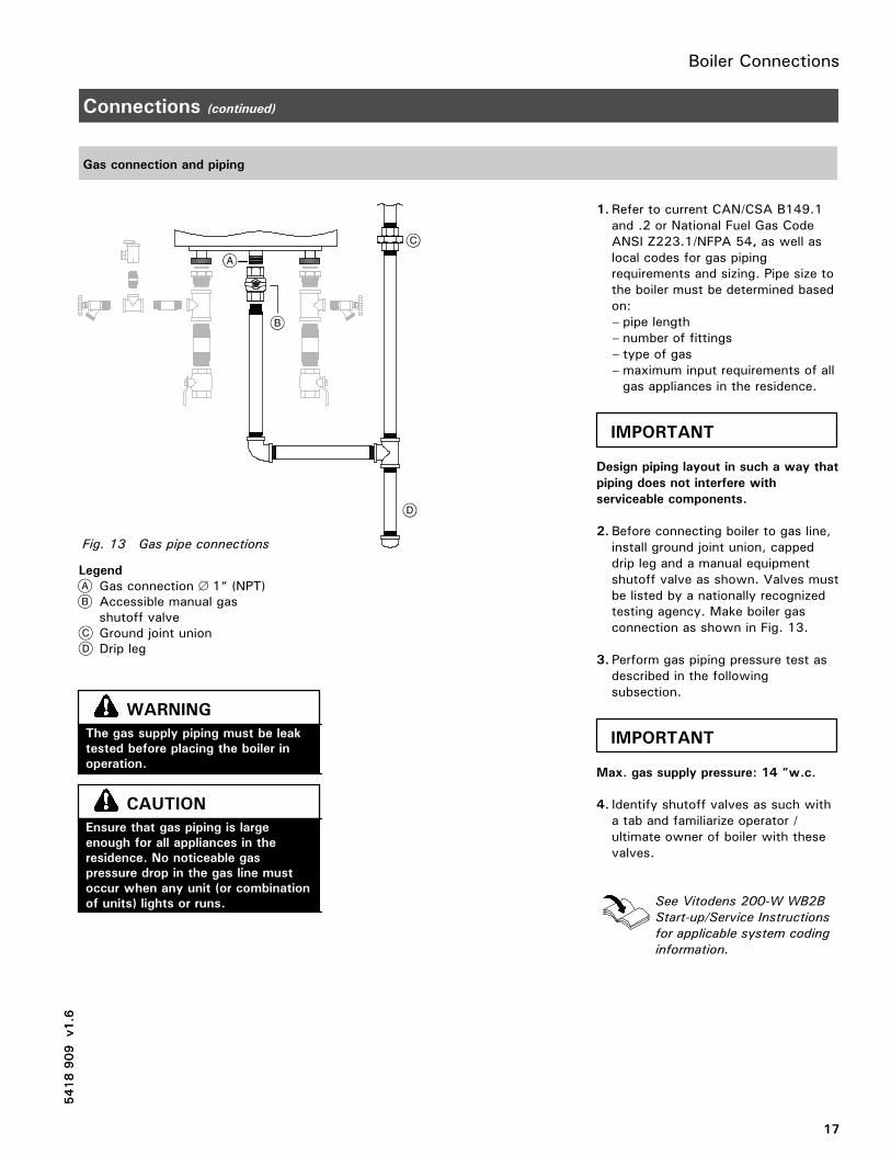
Gas connection and piping
Legend
Gas connection ∅ 1“ (NPT)Accessible manual gasshutoff valveGround joint unionDrip leg
1. Refer to current CAN/CSA B149.1and .2 or National Fuel Gas CodeANSI Z223.1/NFPA 54, as well aslocal codes for gas pipingrequirements and sizing. Pipe size tothe boiler must be determined basedon:– pipe length– number of fittings– type of gas– maximum input requirements of allgas appliances in the residence.
Design piping layout in such a way that
piping does not interfere with
serviceable components.
2. Before connecting boiler to gas line,install ground joint union, cappeddrip leg and a manual equipmentshutoff valve as shown. Valves mustbe listed by a nationally recognizedtesting agency. Make boiler gasconnection as shown in Fig. 13.
3. Perform gas piping pressure test asdescribed in the followingsubsection.
Max. gas supply pressure: 14 “w.c.
4. Identify shutoff valves as such witha tab and familiarize operator /ultimate owner of boiler with thesevalves.
See Vitodens 200-W WB2B
Start-up/Service Instructions
for applicable system coding
information.
5418909
v1.6
Fig. 13 Gas pipe connections
5418909
v1.6
The gas supply piping must be leak
tested before placing the boiler in
operation.
WARNING
Ensure that gas piping is large
enough for all appliances in the
residence. No noticeable gas
pressure drop in the gas line must
occur when any unit (or combination
of units) lights or runs.
CAUTION
IMPORTANT
IMPORTANT
Boiler Connections
18
Connections (continued)
Gas piping pressure test
When performing the gas piping pressure test, ensure the following requirements are met.
½ psig = 14 ”w.c.
1. Isolate the boiler from the gas supplypiping system using the individualmanual shutoff valve during pressuretests equal to or less than ½ psig/14 ”w.c.
2. The boiler and its individual shutoffvalve must be disconnected from thegas supply piping system during anypressure testing of that system attest pressures in excess of ½ psig /14 ”w.c.
3. Perform leak test.Use approved liquid spray solutionfor bubble test. Ensure that no liquidis sprayed on any electricalcomponents, wires or connectors.Do not allow leak detection fluid tocontact gas valve regulator orregulator vent opening.
4.Correct any and all deficiencies.
5. Remove air from gas line.
5418909
v1.6
Never check for gas leaks with an
open flame.
WARNING
Exposing boiler gas pressure
regulator and gas valve to extreme
pressures renders warranty null and
void.
WARNING
IMPORTANT
Boiler Connections
19
Connections (continued)
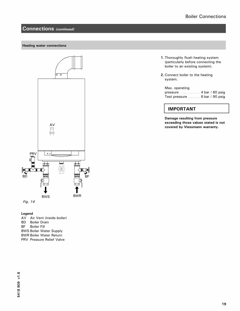
Heating water connections
Legend
AV Air Vent (inside boiler)BD Boiler DrainBF Boiler FillBWS Boiler Water SupplyBWR Boiler Water ReturnPRV Pressure Relief Valve
1. Thoroughly flush heating system(particularly before connecting theboiler to an existing system).
2.Connect boiler to the heatingsystem.
Max. operatingpressure 4 bar / 60 psig. . . . . . . . . . . . . . . . . . . . . . . .
Test pressure 6 bar / 90 psig. . . . . . . . . . . . . .
Damage resulting from pressure
exceeding those values stated is not
covered by Viessmann warranty.
5418909
v1.6
5418909
v1.6
AV
PRV
BWRBWS
BD BF
Fig. 14
IMPORTANT
Boiler Connections
20
Connections (continued)
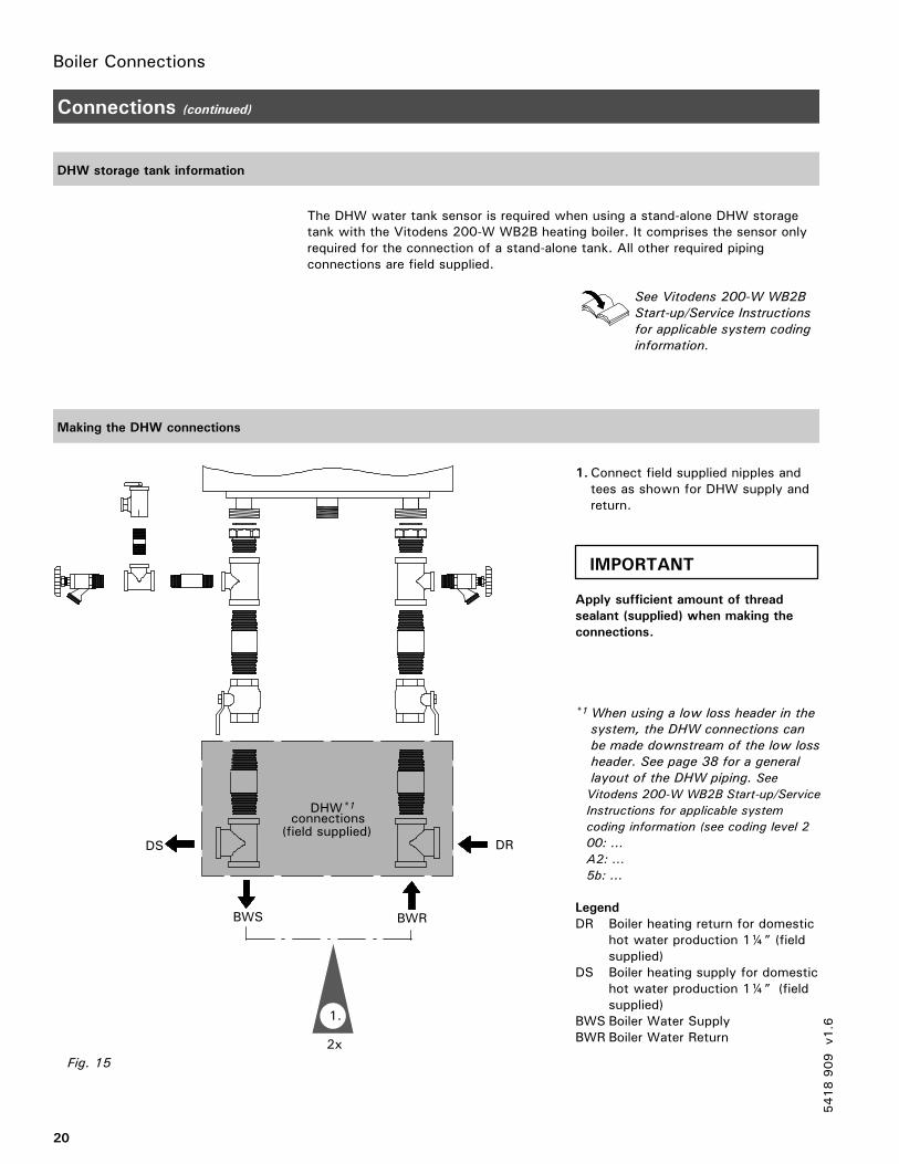
DHW storage tank information
The DHW water tank sensor is required when using a stand-alone DHW storagetank with the Vitodens 200-W WB2B heating boiler. It comprises the sensor onlyrequired for the connection of a stand-alone tank. All other required pipingconnections are field supplied.
See Vitodens 200-W WB2B
Start-up/Service Instructions
for applicable system coding
information.
Making the DHW connections
1.Connect field supplied nipples andtees as shown for DHW supply andreturn.
Apply sufficient amount of thread
sealant (supplied) when making the
connections.
*1When using a low loss header in the
system, the DHW connections can
be made downstream of the low loss
header. See page 38 for a general
layout of the DHW piping. See
Vitodens 200-W WB2B Start-up/Service
Instructions for applicable system
coding information (see coding level 2
00: ...
A2: ...
5b: ...
Legend
DR Boiler heating return for domestichot water production 1¼” (fieldsupplied)
DS Boiler heating supply for domestichot water production 1¼” (fieldsupplied)
BWS Boiler Water SupplyBWR Boiler Water Return
5418909
v1.6
Fig. 15
connections(field supplied)
DS DR
DHW*1
2x
1.
BWRBWS
IMPORTANT
Boiler Connections
21
Connections (continued)
Making the DHW connections (continued)
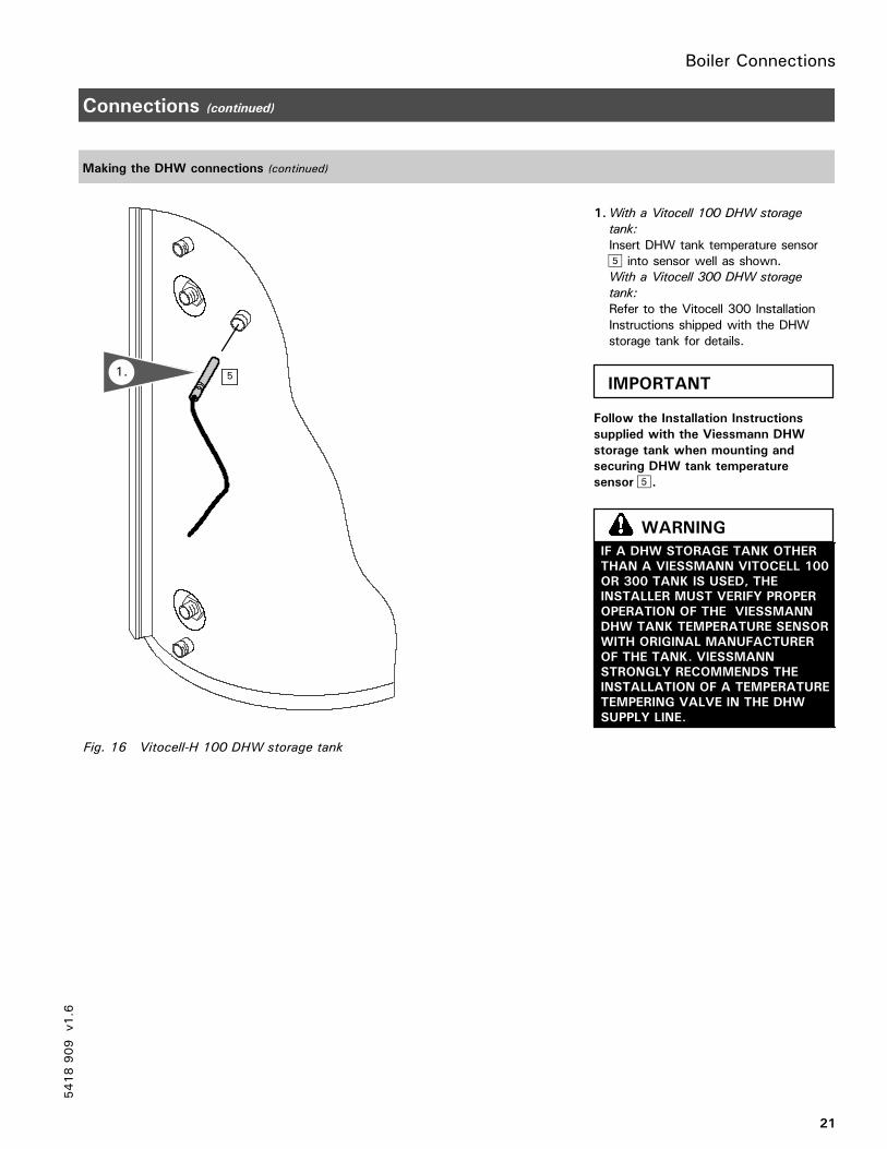
1.With a Vitocell 100 DHW storage
tank:
Insert DHW tank temperature sensorinto sensor well as shown.
With a Vitocell 300 DHW storage
tank:
Refer to the Vitocell 300 InstallationInstructions shipped with the DHWstorage tank for details.
Follow the Installation Instructions
supplied with the Viessmann DHW
storage tank when mounting and
securing DHW tank temperature
sensor .
5418909
v1.6
Fig. 16 Vitocell-H 100 DHW storage tank
51.IMPORTANT
IF A DHW STORAGE TANK OTHER
THAN A VIESSMANN VITOCELL 100
OR 300 TANK IS USED, THE
INSTALLER MUST VERIFY PROPER
OPERATION OF THE VIESSMANN
DHW TANK TEMPERATURE SENSOR
WITH ORIGINAL MANUFACTURER
OF THE TANK. VIESSMANN
STRONGLY RECOMMENDS THE
INSTALLATION OF A TEMPERATURE
TEMPERING VALVE IN THE DHW
SUPPLY LINE.
WARNING
Boiler Connections
22
Connections (continued)
Accessing the control unit cables
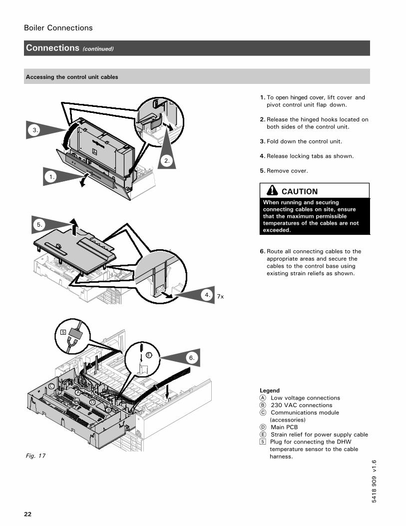
1. To open hinged cover, lift cover andpivot control unit flap down.
2. Release the hinged hooks located onboth sides of the control unit.
3. Fold down the control unit.
4. Release locking tabs as shown.
5. Remove cover.
6. Route all connecting cables to theappropriate areas and secure thecables to the control base usingexisting strain reliefs as shown.
Legend
Low voltage connections230 VAC connectionsCommunications module(accessories)Main PCBStrain relief for power supply cablePlug for connecting the DHWtemperature sensor to the cableharness.
5418909
v1.6
5.
7x
2x
1.
3.
2.
4.
B
C
A
D
E
5
6.
Fig. 17
When running and securing
connecting cables on site, ensure
that the maximum permissible
temperatures of the cables are not
exceeded.
CAUTION
Boiler Connections
23
Connections (continued)
Connecting DHW sensor
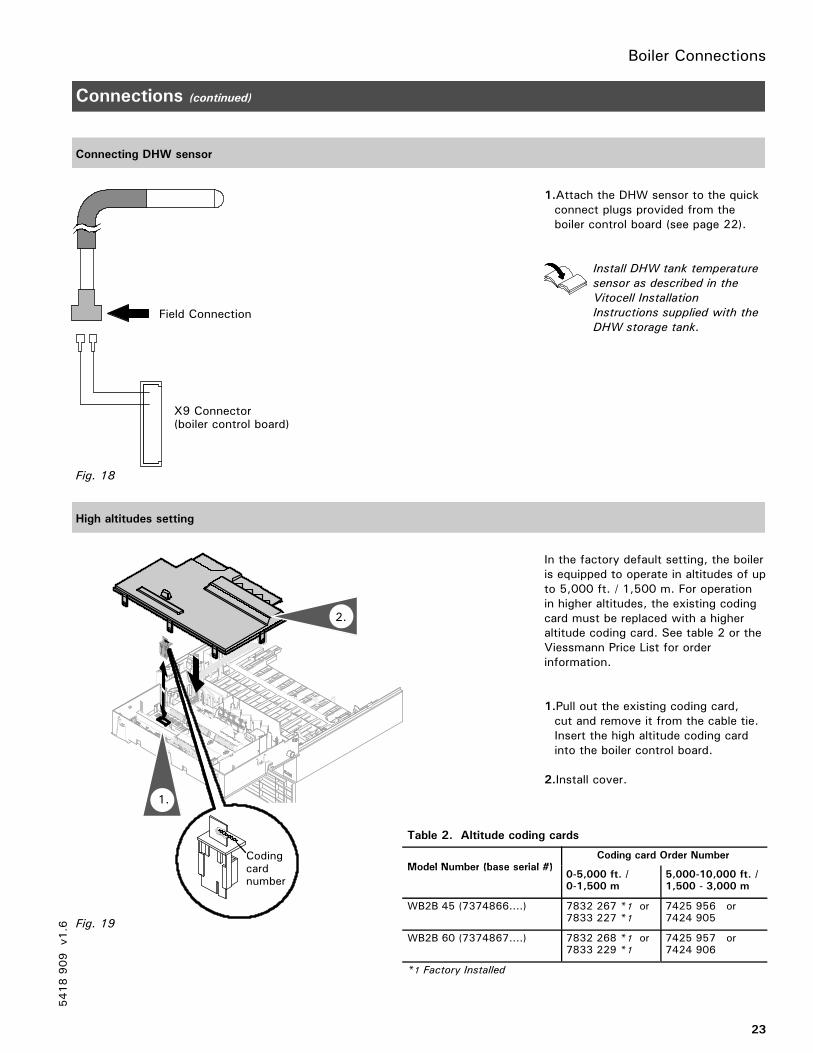
1.Attach the DHW sensor to the quickconnect plugs provided from theboiler control board (see page 22).
Install DHW tank temperature
sensor as described in the
Vitocell Installation
Instructions supplied with the
DHW storage tank.
High altitudes setting
In the factory default setting, the boileris equipped to operate in altitudes of upto 5,000 ft. / 1,500 m. For operationin higher altitudes, the existing codingcard must be replaced with a higheraltitude coding card. See table 2 or theViessmann Price List for orderinformation.
1.Pull out the existing coding card,cut and remove it from the cable tie.Insert the high altitude coding cardinto the boiler control board.
2.Install cover.
Table 2. Altitude coding cards
Model Number (base serial #)Coding card Order Number
Model Number (base serial #)0-5,000 ft. /0-1,500 m
5,000-10,000 ft. /1,500 - 3,000 m
WB2B 45 (7374866....) 7832 267 *1 or7833 227 *1
7425 956 or7424 905
WB2B 60 (7374867....) 7832 268 *1 or7833 229 *1
7425 957 or7424 906
*1 Factory Installed
5418909
v1.6
Field Connection
X9 Connector(boiler control board)
Fig. 18
Codingcardnumber
Fig. 19
1.
2.
Boiler Connections
24
Connections (continued)
Condensate connection
The Vitodens 200-W WB2B boiler comes with a built-in condensate trap. An external trap is not required when connectingthe field drain to flexible discharge tubing. Discharge tubing (field supplied) must be of 1” diameter. Use CPVC, PVC orother material approved by codes listed below.
The drain pipe and fittings must conform to ANSI standards and ASTM D1785 or D2846. CPVC or PVC cement and primermust conform to ASTM D2564 or F493. In Canada use CSA or ULC listed schedule 40 CPVC or PVC drain pipe, fittingsand cement.
If the condensate outlet of the Vitodens 200-W WB2B boiler is lower than the drain, a condensate pump must be installed.Select a pump which is approved for condensing boiler applications. To avoid condensate spillage, select a pump with anoverflow switch. The drain connection must terminate into an open or vented drain as close to the boiler as possible toprevent siphoning of the boiler drain.
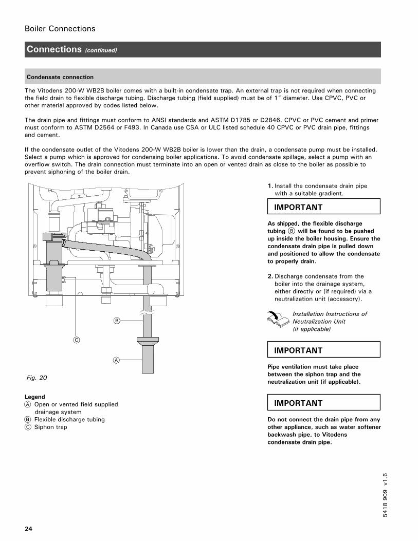
Legend
Open or vented field supplieddrainage systemFlexible discharge tubingSiphon trap
1. Install the condensate drain pipewith a suitable gradient.
As shipped, the flexible discharge
tubing B will be found to be pushed
up inside the boiler housing. Ensure the
condensate drain pipe is pulled down
and positioned to allow the condensate
to properly drain.
2.Discharge condensate from theboiler into the drainage system,either directly or (if required) via aneutralization unit (accessory).
Installation Instructions of
Neutralization Unit
(if applicable)
Pipe ventilation must take place
between the siphon trap and the
neutralization unit (if applicable).
Do not connect the drain pipe from any
other appliance, such as water softener
backwash pipe, to Vitodens
condensate drain pipe.
5418909
v1.6
Fig. 20
IMPORTANT
IMPORTANT
IMPORTANT
Boiler Connections
25
Safety Connections and Pressure Testing
Installing boiler safety devices
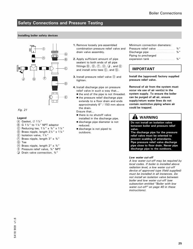
Legend
Gasket, ∅ 1½”G 1½” to 1¼” NPT adaptorReducing tee, 1¼” x ¾” x 1¼”Brass nipple, length 2½” x 1¼”Isolation valve, 1¼”Brass nipple, length 3” x ¾”TeeBrass nipple, length 2” x ¾”
I Pressure relief valve, ¾” NPTJ Drain valve connection, ¾”
1. Remove loosely pre-assembledcombination pressure relief valve anddrain valve assembly.
2.Apply sufficient amount of pipesealant to both ends of all pipe
fittings , , , , J , and
and install onto tees , and .
3. Install pressure relief valve I andtighten.
4. Install discharge pipe on pressurerelief valve in such a way that...� the end of the pipe is not threaded.� the pressure relief discharge pipeextends to a floor drain and endsapproximately 6” / 150 mm abovethe drain.
Ensure that...� there is no shutoff valveinstalled in the discharge pipe.
� discharge pipe diameter is notreduced.
� discharge is not piped tooutdoors.
Minimum connection diameters:Pressure relief valve ¾“. . . . . . . . . . . . . . . . . . . . . . . . . . . .
Discharge pipe ¾“. . . . . . . . . . . . . . . . . . . . . . . . . . . . . . . . . . . . . . . .
Piping to prechargedexpansion tank ¾“. . . . . . . . . . . . . . . . . . . . . . . . . . . . . . . . . . . . . .
Install the (approved) factory supplied
pressure relief valve.
Removal of air from the system must
occur via use of air vent(s) in the
system supply. To ensure the boiler
can be purged of all air, ensure
supply/return water lines do not
contain restrictive piping where air
could be trapped.
Low water cut-off
A low water cut-off may be required by
local codes. If boiler is installed above
radiation level, a low water cut-offdevice of approved type (field supplied)
must be installed in all instances. Do
not install an isolation valve between
boiler and low water cut-off (see
subsection entitled “Boiler with lowwater cut-off” on page 40 in these
instructions).
5418909
v1.6
J
I
Fig. 21
IMPORTANT
Do not install an isolation valve
between boiler and pressure relief
valve.
The discharge pipe for the pressure
relief valve must be oriented to
prevent scalding of attendants.
Pipe pressure relief valve discharge
pipe close to floor drain. Never pipe
discharge pipe to the outdoors.
WARNING
Boiler Connections
26
Safety Connections and Pressure Testing (continued)
Performing a boiler pressure test
The boiler must be leak tested beforebeing placed in operation. Before boileris connected to piping or electricalpower supply, it must behydrostatically pressure tested.
1.After installing safety devices (seeprevious page), install temporary capon ¾” x 2” nipple.
2.Cap supply and return connections.
3.Connect ½” garden hose to boiler fillvalve at the bottom of the boiler andfill boiler slowly until pressure gageindicates max. 4 bar / 60 psig.
4.Maintain pressure for 15 minutes.During time of pressure testing, donot leave boiler unattended.
5. Inspect all pipe joint connections andsafety devices with a flashlight forleaks.A lower manometer reading than4 bar / 60 psig usually indicates lossof water due to leakage. All leaksmust be repaired.
6.After 15 minutes, release waterpressure from boiler by openingboiler drain valve slowly, removecaps from supply and returnconnections as well as ¾” cap from2” nipple, and install pressure reliefvalve immediately instead of ¾”cap.
7.After boiler has passed pressuretest, proceed with the installation.
Max. operating pressure4 bar / 60 psig. . . . . . . . . . . . . . . . . . . . . . . . . . . . . . . . . . . . . . . . . . . . . . . .
Testing pressure6 bar / 90 psig. . . . . . . . . . . . . . . . . . . . . . . . . . . . . . . . . . . . . . . . . . . . . . .
Max. boiler water temperature210°F / 99°C. . . . . . . . . . . . . . . . . . . . . . . . . . . . . . . . . . . . . . . . . . . . . . . . .
5418909
v1.6
Exposing the boiler to pressures and
temperatures in excess of those
listed will result in damages, and will
render warranty null and void.
WARNING
27
Installation Examples
General
The schematics on the following pagesare to be seen as guidelines only. Theyfurther do not display all systemvarieties, safety devices, or conceptspossible. Specific system layouts maybe further discussed with the localViessmann sales representative office.
Clearances
A minimum of 2” / 51 mmcircumferential clearance fromnon-insulated hot water pipes tocombustible construction must bemaintained. In cases where the pipesare insulated with pipe insulation ofappropriate and sufficient thicknessand insulation values, the aboveclearance may be reduced to 0” (referto local gas codes).
Please note that in the following piping layout examples all pumps are field supplied.
The examples on the following pages
depict possible piping layouts of the
Vitodens 200-W WB2B boiler equipped
with Viessmann System Technology.
For boiler and tank combinations,
please install only feasible
combinations listed in the Viessmann
Price List.
Please note that the following
examples are simplified conceptual
drawings only!
Piping and necessary componentry
must be field verified.
A low water cut-off (LWCO) must be
installed where required by local codes.
Proper installation and functionality in
the field is the responsibility of the
heating contractor.
DHW supply and return piping between
boiler DHW connections and the
Viessmann DHW tank connections,
shall be a minimum of 1¼” pipe size.This will ensure the residual head of
the field supplied pump is fully utilized
to overcome the resistance of the DHW
heat exchanger coil and to provide
sufficient water flow to the boiler heat
exchanger.
In non-Viessmann DHW tank
applications, perform, in addition to the
above, accurate calculations for DHW
tank coil pressure drop versus boiler
pump (field supplied) residual head to
ensure sufficient water flow to the
boiler heat exchanger. Failure to heed
the above instructions may cause boiler
short-cycling and inadequate DHW
supply.
5418909
v1.6
For underfloor heating applications,
an additional immersion or strap-on
aquastat must be installed in the low
temperature underfloor loop
(downstream of the mixing valve) to
de-energize the pump and/or boiler to
prevent overheating. High water
temperatures can damage concrete
slabs.
CAUTION
IMPORTANT
If a DHW storage tank other than a
Viessmann Vitocell 100 or 300 tank
is used, the installer must verify
proper operation of the Viessmann
DHW tank temperature sensor with
the original manufacturer of the tank.
Viessmann strongly recommends the
installation of a temperature
tempering valve in the DHW supply
line.
WARNING IMPORTANT
Boiler Connections
28
Installation Examples (continued)
Waterside flow (primary circuit)
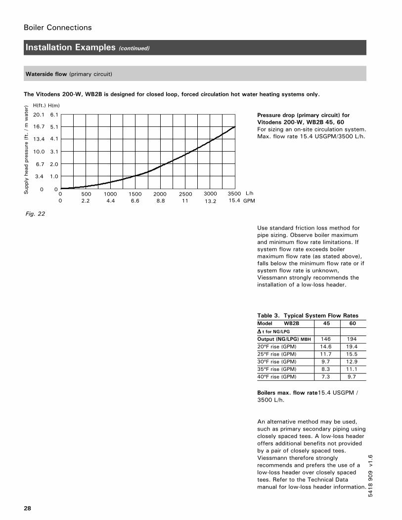
The Vitodens 200-W, WB2B is designed for closed loop, forced circulation hot water heating systems only.
Pressure drop (primary circuit) for
Vitodens 200-W, WB2B 45, 60
For sizing an on-site circulation system.Max. flow rate 15.4 USGPM/3500 L/h.
Use standard friction loss method forpipe sizing. Observe boiler maximumand minimum flow rate limitations. Ifsystem flow rate exceeds boilermaximum flow rate (as stated above),falls below the minimum flow rate or ifsystem flow rate is unknown,Viessmann strongly recommends theinstallation of a low-loss header.
Table 3. Typical System Flow Rates
Model WB2B 45 60
∆∆∆∆ t for NG/LPG
Output (NG/LPG) MBH 146 194
20ºF rise (GPM) 14.6 19.4
25ºF rise (GPM) 11.7 15.5
30ºF rise (GPM) 9.7 12.9
35ºF rise (GPM) 8.3 11.1
40ºF rise (GPM) 7.3 9.7
Boilers max. flow rate15.4 USGPM /3500 L/h.
An alternative method may be used,such as primary secondary piping usingclosely spaced tees. A low-loss headeroffers additional benefits not providedby a pair of closely spaced tees.Viessmann therefore stronglyrecommends and prefers the use of alow-loss header over closely spacedtees. Refer to the Technical Datamanual for low-loss header information.
5418909
v1.6
H(ft.) H(m)
20.1 6.1
16.7 5.1
13.4 4.1
10.0 3.1
6.7 2.0
3.4 1.0
0 0
00 500 1000 1500 2000 2500 3000 3500 L/h
2.2 4.4 6.6 8.8 11 13.2 15.4 GPM
Supplyheadpressure(ft./mwater)
Fig. 22
Boiler Connections
29
Installation Examples (continued)
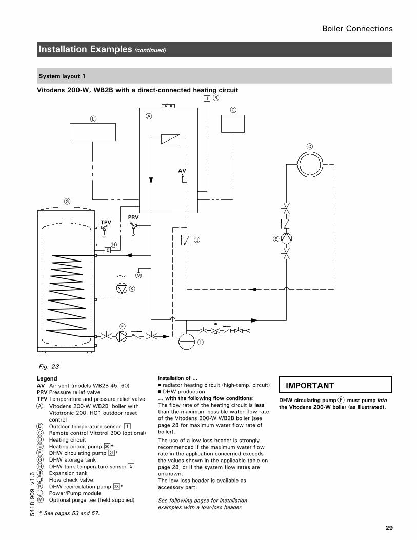
System layout 1
Vitodens 200-W, WB2B with a direct-connected heating circuit
LegendAV Air vent (models WB2B 45, 60)PRV Pressure relief valveTPV Temperature and pressure relief valve
Vitodens 200-W WB2B boiler withVitotronic 200, HO1 outdoor resetcontrolOutdoor temperature sensorRemote control Vitotrol 300 (optional)Heating circuitHeating circuit pump sÖ*DHW circulating pump sA*DHW storage tankDHW tank temperature sensor
I Expansion tankJ Flow check valve
DHW recirculation pump sK*Power/Pump module
M Optional purge tee (field supplied)
* See pages 53 and 57.
Installation of ...
� radiator heating circuit (high-temp. circuit)� DHW production... with the following flow conditions:
The flow rate of the heating circuit is lessthan the maximum possible water flow rateof the Vitodens 200-W WB2B boiler (seepage 28 for maximum water flow rate ofboiler).
The use of a low-loss header is stronglyrecommended if the maximum water flowrate in the application concerned exceedsthe values shown in the applicable table onpage 28, or if the system flow rates areunknown.The low-loss header is available asaccessory part.
See following pages for installation
examples with a low-loss header.
DHW circulating pump must pump into
the Vitodens 200-W boiler (as illustrated).
5418909
v1.6
5
1
PRVTPV
A
B
C
K
AV
M
D
E
F
G
H
L
J
I
Fig. 23
IMPORTANT
Boiler Connections
30
Installation Examples (continued)
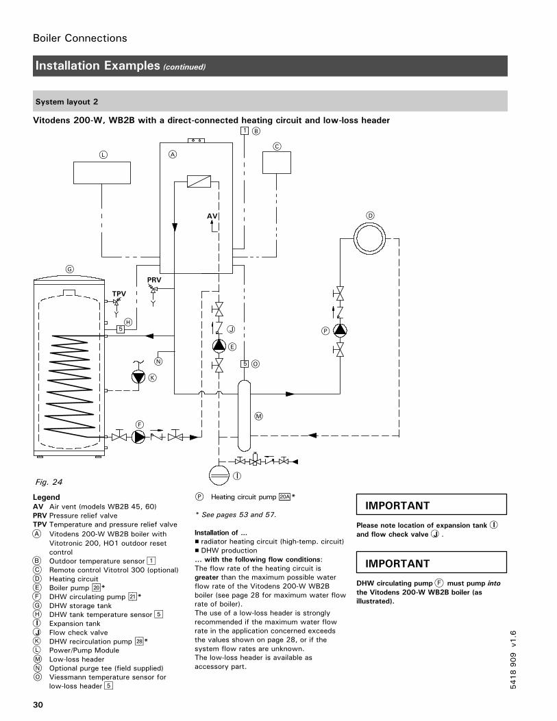
System layout 2
Vitodens 200-W, WB2B with a direct-connected heating circuit and low-loss header
LegendAV Air vent (models WB2B 45, 60)PRV Pressure relief valveTPV Temperature and pressure relief valve
Vitodens 200-W WB2B boiler withVitotronic 200, HO1 outdoor resetcontrolOutdoor temperature sensorRemote control Vitotrol 300 (optional)Heating circuitBoiler pump sÖ*DHW circulating pump sA*DHW storage tankDHW tank temperature sensor
I Expansion tankJ Flow check valve
DHW recirculation pump sK*Power/Pump Module
M Low-loss headerN Optional purge tee (field supplied)O Viessmann temperature sensor for
low-loss header
P Heating circuit pump 20A *
* See pages 53 and 57.
Installation of ...
� radiator heating circuit (high-temp. circuit)� DHW production... with the following flow conditions:The flow rate of the heating circuit isgreater than the maximum possible waterflow rate of the Vitodens 200-W WB2Bboiler (see page 28 for maximum water flowrate of boiler).The use of a low-loss header is stronglyrecommended if the maximum water flowrate in the application concerned exceedsthe values shown on page 28, or if thesystem flow rates are unknown.The low-loss header is available asaccessory part.
Please note location of expansion tank I
and flow check valve J .
DHW circulating pump must pump into
the Vitodens 200-W WB2B boiler (as
illustrated).
5418909
v1.6
1
PRV
TPV
5
A
B
C
K
M
D
E
F
G
H
L
N O
AV
5
I
P
Fig. 24
J
IMPORTANT
IMPORTANT
Boiler Connections
31
Installation Examples (continued)
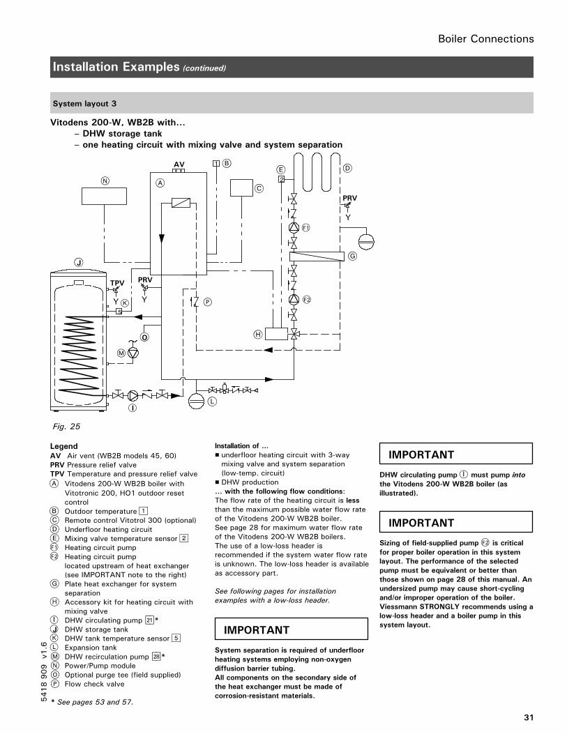
System layout 3
Vitodens 200-W, WB2B with...
– DHW storage tank
– one heating circuit with mixing valve and system separation
LegendAV Air vent (WB2B models 45, 60)PRV Pressure relief valveTPV Temperature and pressure relief valve
Vitodens 200-W WB2B boiler withVitotronic 200, HO1 outdoor resetcontrolOutdoor temperatureRemote control Vitotrol 300 (optional)Underfloor heating circuitMixing valve temperature sensor
F1 Heating circuit pumpF2 Heating circuit pump
located upstream of heat exchanger(see IMPORTANT note to the right)Plate heat exchanger for systemseparationAccessory kit for heating circuit withmixing valve
I DHW circulating pump sA*J DHW storage tank
DHW tank temperature sensorExpansion tank
M DHW recirculation pump sK*N Power/Pump moduleO Optional purge tee (field supplied)P Flow check valve
* See pages 53 and 57.
Installation of ...
� underfloor heating circuit with 3-waymixing valve and system separation(low-temp. circuit)
� DHW production... with the following flow conditions:The flow rate of the heating circuit is lessthan the maximum possible water flow rateof the Vitodens 200-W WB2B boiler.See page 28 for maximum water flow rateof the Vitodens 200-W WB2B boilers.The use of a low-loss header isrecommended if the system water flow rateis unknown. The low-loss header is availableas accessory part.
See following pages for installation
examples with a low-loss header.
System separation is required of underfloor
heating systems employing non-oxygen
diffusion barrier tubing.
All components on the secondary side of
the heat exchanger must be made of
corrosion-resistant materials.
DHW circulating pump I must pump into
the Vitodens 200-W WB2B boiler (as
illustrated).
Sizing of field-supplied pump F2 is critical
for proper boiler operation in this system
layout. The performance of the selected
pump must be equivalent or better than
those shown on page 28 of this manual. An
undersized pump may cause short-cycling
and/or improper operation of the boiler.
Viessmann STRONGLY recommends using a
low-loss header and a boiler pump in this
system layout.
5418909
v1.6
TPV
AV
Y
I
F1
F2
5
1
YY
PRV
PRV
J
O
2
M
N
P
Fig. 25
IMPORTANT
IMPORTANT
IMPORTANT
Boiler Connections
32
Installation Examples (continued)
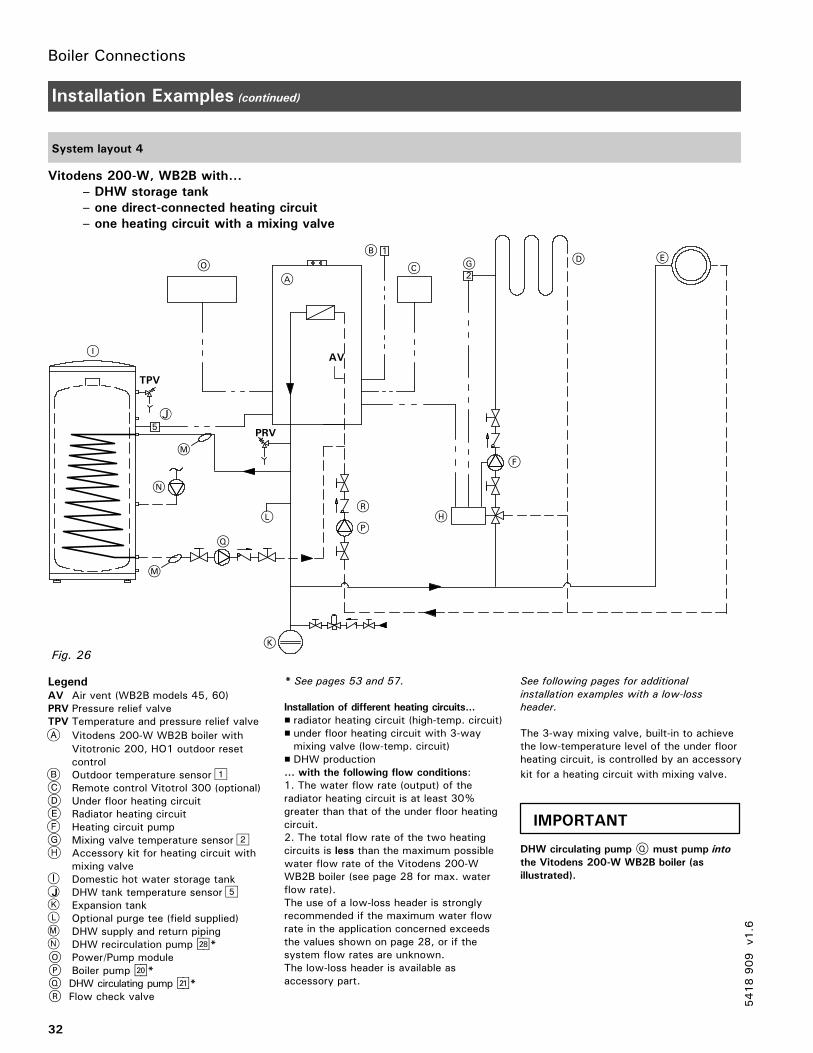
System layout 4
Vitodens 200-W, WB2B with...
– DHW storage tank
– one direct-connected heating circuit
– one heating circuit with a mixing valve
LegendAV Air vent (WB2B models 45, 60)PRV Pressure relief valveTPV Temperature and pressure relief valve
Vitodens 200-W WB2B boiler withVitotronic 200, HO1 outdoor resetcontrolOutdoor temperature sensorRemote control Vitotrol 300 (optional)Under floor heating circuitRadiator heating circuitHeating circuit pumpMixing valve temperature sensorAccessory kit for heating circuit withmixing valve
I Domestic hot water storage tankJ DHW tank temperature sensor
Expansion tankOptional purge tee (field supplied)DHW supply and return pipingDHW recirculation pump sK*
O Power/Pump moduleP Boiler pump sÖ*Q DHW circulating pump sA*R Flow check valve
* See pages 53 and 57.
Installation of different heating circuits...
� radiator heating circuit (high-temp. circuit)� under floor heating circuit with 3-waymixing valve (low-temp. circuit)
� DHW production... with the following flow conditions:1. The water flow rate (output) of theradiator heating circuit is at least 30%greater than that of the under floor heatingcircuit.2. The total flow rate of the two heatingcircuits is less than the maximum possiblewater flow rate of the Vitodens 200-WWB2B boiler (see page 28 for max. waterflow rate).The use of a low-loss header is stronglyrecommended if the maximum water flowrate in the application concerned exceedsthe values shown on page 28, or if thesystem flow rates are unknown.The low-loss header is available asaccessory part.
See following pages for additional
installation examples with a low-loss
header.
The 3-way mixing valve, built-in to achievethe low-temperature level of the under floorheating circuit, is controlled by an accessory
kit for a heating circuit with mixing valve.
DHW circulating pump Q must pump into
the Vitodens 200-W WB2B boiler (as
illustrated).
5418909
v1.6
PRV
TPV
A
B
C
K
M
D E
F
HL
O
AV
G
I
N
1
V
2
5
R
Q
J
P
M
Fig. 26
IMPORTANT
Boiler Connections
33
Installation Examples (continued)
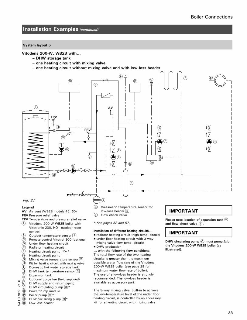
System layout 5
Vitodens 200-W, WB2B with...
– DHW storage tank
– one heating circuit with mixing valve
– one heating circuit without mixing valve and with low-loss header
LegendAV Air vent (WB2B models 45, 60)PRV Pressure relief valveTPV Temperature and pressure relief valve
Vitodens 200-W WB2B boiler withVitotronic 200, HO1 outdoor resetcontrolOutdoor temperature sensorRemote control Vitotrol 300 (optional)Under floor heating circuitRadiator heating circuitHeating circuit pump 20A *
F1 Heating circuit pumpMixing valve temperature sensorKit for heating circuit with mixing valve
I Domestic hot water storage tankJ DHW tank temperature sensor
Expansion tankOptional purge tee (field supplied)DHW supply and return pipingDHW circulating pump sK*
O Power/Pump moduleP Boiler pump sÖ*Q DHW circulating pump sA*R Low-loss header
S Viessmann temperature sensor forlow-loss header
T Flow check valve
* See pages 53 and 57.
Installation of different heating circuits...
� radiator heating circuit (high-temp. circuit)� under floor heating circuit with 3-waymixing valve (low-temp. circuit)
� DHW production... with the following flow conditions:The total flow rate of the two heatingcircuits is greater than the maximumpossible water flow rate of the Vitodens200-W WB2B boiler (see page 28 formaximum water flow rate of boiler).The use of a low-loss header is stronglyrecommended. The low-loss header isavailable as accessory part.
The 3-way mixing valve, built-in to achievethe low-temperature level of the under floorheating circuit, is controlled by an accessorykit for a heating circuit with mixing valve.
Please note location of expansion tank
and flow check valve T.
DHW circulating pump Q must pump into
the Vitodens 200-W WB2B boiler (as
illustrated).
5418909
v1.6
PRV
TPV
A
B
C
K
M
D E
F
H
L
N
O
T
AV
5
1
2
5
G
I
R
Q
M
P
S
F1
Fig. 27
J
IMPORTANT
IMPORTANT
Boiler Connections
34
Installation Examples (continued)
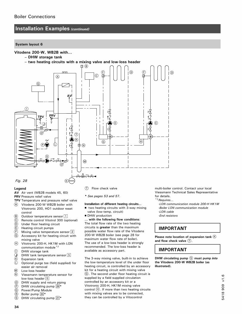
System layout 6
Vitodens 200-W, WB2B with...
– DHW storage tank
– two heating circuits with a mixing valve and low-loss header
LegendAV Air vent (WB2B models 45, 60)PRV Pressure relief valveTPV Temperature and pressure relief valve
Vitodens 200-W WB2B boiler withVitotronic 200, HO1 outdoor resetcontrolOutdoor temperature sensorRemote control Vitotrol 300 (optional)Under floor heating circuitHeating circuit pumpsMixing valve temperature sensorAccessory kit for heating circuit withmixing valveVitotronic 200-H, HK1M with LONcommunication module*1
I DHW storage tankJ DHW tank temperature sensor
Expansion tankOptional purge tee (field supplied) foreasier air removalLow-loss headerViessmann temperature sensor forlow-loss header
O DHW supply and return pipingP DHW circulating pump sK*Q Power/Pump ModuleR Boiler pump sÖ*S DHW circulating pump sA*
T Flow check valve
* See pages 53 and 57.
Installation of different heating circuits...
� two heating circuits with 3-way mixingvalve (low-temp. circuit)
� DHW production... with the following flow conditions:The total flow rate of the two heatingcircuits is greater than the maximumpossible water flow rate of the Vitodens200-W WB2B boiler (see page 28 formaximum water flow rate of boiler).The use of a low-loss header is stronglyrecommended. The low-loss header isavailable as accessory part.
The 3-way mixing valve, built-in to achievethe low-temperature level of the under floorheating circuit, is controlled by an accessorykit for a heating circuit with mixing valve
. The second under floor heating circuit issupplied by a field supplied circulationcontrolled by an accessory kit or aVitotronic 200-H, HK1M mixing valvecontrol . If more than two heating circuitswith mixing valves are to be connected,they can be controlled by a Vitocontrol
multi-boiler control. Contact your localViessmann Technical Sales Representativefor details.*1Requires...
-LON communication module 200-H HK1M
-Boiler LON communication module
-LON cable
-End resistors
Please note location of expansion tank
and flow check valve T.
DHW circulating pump S must pump into
the Vitodens 200-W WB2B boiler (as
illustrated).
5418909
v1.6
1
TPV
2
5
2
PRV
A
B
CD
E
F
G H
I
K
L
M
N
O
S
AV
R
T
D
E
F
P
Q
5
O
Fig. 28
J
IMPORTANT
IMPORTANT

Boiler Connections
35
Installation Examples (continued)
System layout 7
Vitodens 200-W, WB2B with...
– direct-connected heating circuit
– one heating circuit with system separation
LegendAV Air vent (WB2B models 45, 60)PRV Pressure relief valveTPV Temperature and pressure relief valve
Vitodens 200-W WB2B boiler withVitotronic 200, HO1 outdoor resetcontrolOutdoor temperature sensorRemote control Vitotrol 300 (optional)Under floor heating circuitHeating circuit pumpPlate heat exchanger for systemseparationHeating circuit pumpMixing valve temperature sensor
I Accessory kit for heating circuit withmixing valve
J DHW storage tankDHW tank temperature sensorExpansion tanksOptional purge tee (field supplied)DHW supply and return piping
O DHW recirculation pump sK*P Boiler pump sÖ*Q DHW circulating pump sA*R Power/pump moduleS Flow check valve
* See pages 53 and 57.
Installation of different heating circuits...
� radiator heating circuit (high-temp. circuit)� under floor heating circuit with 3-waymixing valve (low-temp. circuit)
� DHW production... with the following flow conditions:The total flow rate of the two heatingcircuits is less than the maximum possiblewater flow rate of the Vitodens 200-WWB2B boiler (see page 28 for maximumwater flow rate of boiler).The use of a low-loss header is stronglyrecommended if the maximum water flowrate in the application concerned exceedsthe max. boiler flow rate, or if the systemflow rates are unknown. The low-lossheader is available as accessory part.The 3-way mixing valve, built-in to achievethe low-temperature level of the under floorheating circuit, is controlled by an accessorykit for a heating circuit with mixing valveI . The boiler pump sÖ supplies theradiator heating circuit and the plate heatexchanger for system separation.
The pressure drop (secondary circuit) of the
plate heat exchanger must be less/equal
to the pressure drop of the 3-way mixing
valve. This must be taken into account
when sizing the plate heat exchanger.
DHW circulating pump Q must pump into
the Vitodens 200-W WB2B boiler (as
illustrated).
5418909
v1.6
TPV
PRV
A
BC D
G
I
K
L
M
N
S
RE
F
PQ
5
1
V
2
O
AV
N
Fig. 29
J
IMPORTANT
IMPORTANT
Boiler Connections
36
Installation Examples (continued)
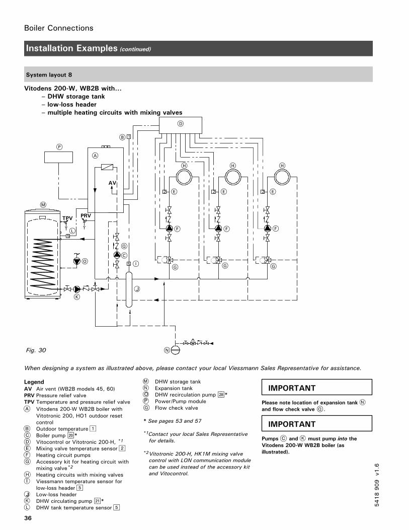
System layout 8
Vitodens 200-W, WB2B with...
– DHW storage tank
– low-loss header
– multiple heating circuits with mixing valves
When designing a system as illustrated above, please contact your local Viessmann Sales Representative for assistance.
LegendAV Air vent (WB2B models 45, 60)PRV Pressure relief valveTPV Temperature and pressure relief valve
Vitodens 200-W WB2B boiler withVitotronic 200, HO1 outdoor resetcontrolOutdoor temperatureBoiler pump sÖ*Vitocontrol or Vitotronic 200-H, *1
Mixing valve temperature sensorHeating circuit pumpsAccessory kit for heating circuit withmixing valve*2
Heating circuits with mixing valvesI Viessmann temperature sensor for
low-loss headerJ Low-loss header
DHW circulating pump sA*DHW tank temperature sensor
DHW storage tankExpansion tank
O DHW recirculation pump sK*P Power/Pump moduleQ Flow check valve
* See pages 53 and 57
*1Contact your local Sales Representative
for details.
*2Vitotronic 200-H, HK1M mixing valve
control with LON communication module
can be used instead of the accessory kit
and Vitocontrol.
Please note location of expansion tank
and flow check valve Q.
Pumps and must pump into the
Vitodens 200-W WB2B boiler (as
illustrated).
5418909
v1.6
5
1
PRV
5
2 2
AV
A
B
C
D
E E E
F F F
G G G
H H H
K
L
M
N
O
P
Q
2
TPV
I
Fig. 30
J
IMPORTANT
IMPORTANT
Boiler Connections
37
Installation Examples (continued)
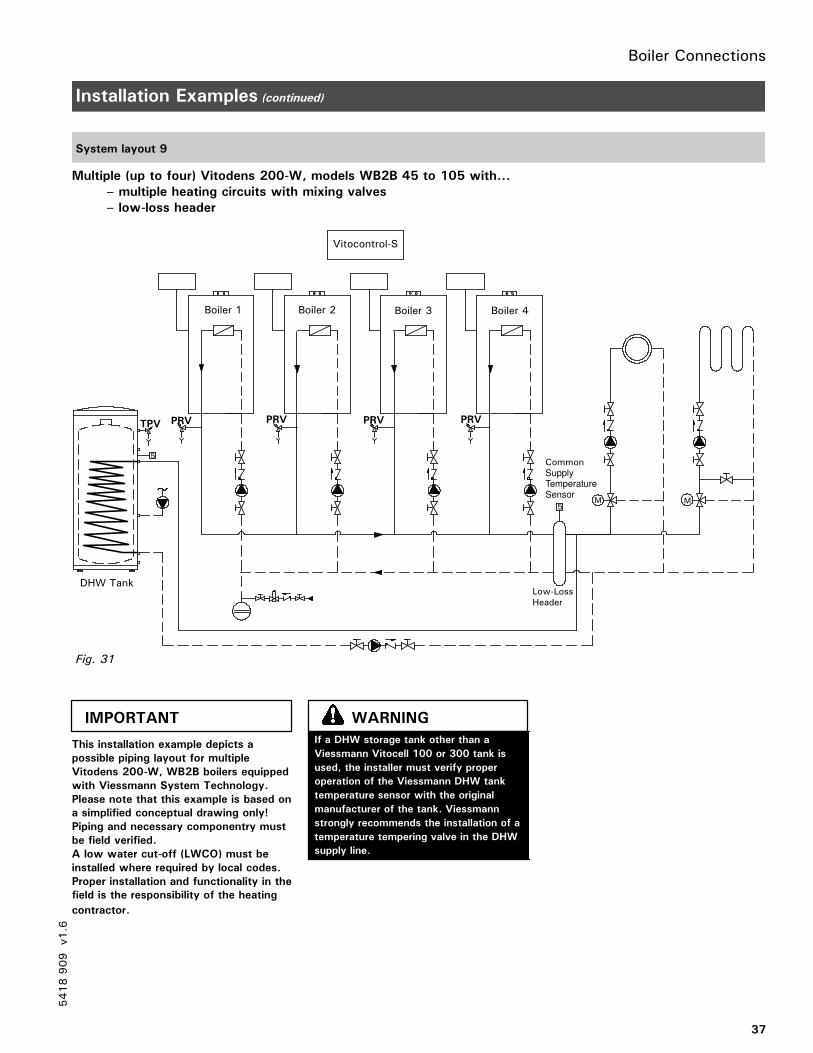
System layout 9
Multiple (up to four) Vitodens 200-W, models WB2B 45 to 105 with...
– multiple heating circuits with mixing valves
– low-loss header
This installation example depicts a
possible piping layout for multiple
Vitodens 200-W, WB2B boilers equipped
with Viessmann System Technology.
Please note that this example is based on
a simplified conceptual drawing only!
Piping and necessary componentry must
be field verified.
A low water cut-off (LWCO) must be
installed where required by local codes.
Proper installation and functionality in the
field is the responsibility of the heating
contractor.
5418909
v1.6
Vitocontrol-S
Boiler 1 Boiler 2 Boiler 3 Boiler 4
PRV PRV PRV PRVTPV
DHW TankLow-LossHeader
CommonSupplyTemperatureSensor
5
5M M
Fig. 31
IMPORTANT
If a DHW storage tank other than a
Viessmann Vitocell 100 or 300 tank is
used, the installer must verify proper
operation of the Viessmann DHW tank
temperature sensor with the original
manufacturer of the tank. Viessmann
strongly recommends the installation of a
temperature tempering valve in the DHW
supply line.
WARNING
Boiler Connections
38
Installation Examples (continued)
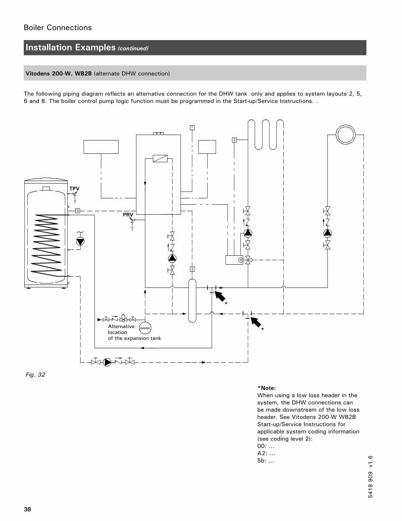
Vitodens 200-W, WB2B (alternate DHW connection)
The following piping diagram reflects an alternative connection for the DHW tank only and applies to system layouts 2, 5,6 and 8. The boiler control pump logic function must be programmed in the Start-up/Service Instructions. .
M
5
1
2
5
PRV
TPV
Alternativelocationof the expansion tank
Fig. 32
*
*
*Note:
When using a low loss header in thesystem, the DHW connections canbe made downstream of the low lossheader. See Vitodens 200-W WB2BStart-up/Service Instructions forapplicable system coding information(see coding level 2):00: ...A2: ...5b: ...
5418909
v1.6
Boiler Connections
39
Installation Examples (continued)
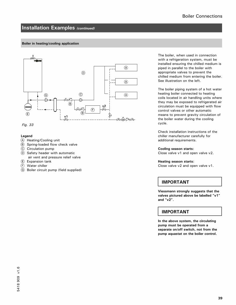
Boiler in heating/cooling application
Legend
Heating/Cooling unitSpring-loaded flow check valveCirculation pumpSafety header with automaticair vent and pressure relief valveExpansion tankWater chillerBoiler circuit pump (field supplied)
The boiler, when used in connectionwith a refrigeration system, must beinstalled ensuring the chilled medium ispiped in parallel to the boiler withappropriate valves to prevent thechilled medium from entering the boiler.See illustration on the left.
The boiler piping system of a hot waterheating boiler connected to heatingcoils located in air handling units wherethey may be exposed to refrigerated aircirculation must be equipped with flowcontrol valves or other automaticmeans to prevent gravity circulation ofthe boiler water during the coolingcycle.
Check installation instructions of thechiller manufacturer carefully foradditional requirements.
Cooling season starts:
Close valve v1 and open valve v2.
Heating season starts:
Close valve v2 and open valve v1.
Viessmann strongly suggests that the
valves pictured above be labelled “v1”
and “v2”.
In the above system, the circulating
pump must be operated from a
separate on/off switch, not from the
pump aquastat on the boiler control.
5418909
v1.6
v2
v1
Fig. 33
IMPORTANT
IMPORTANT
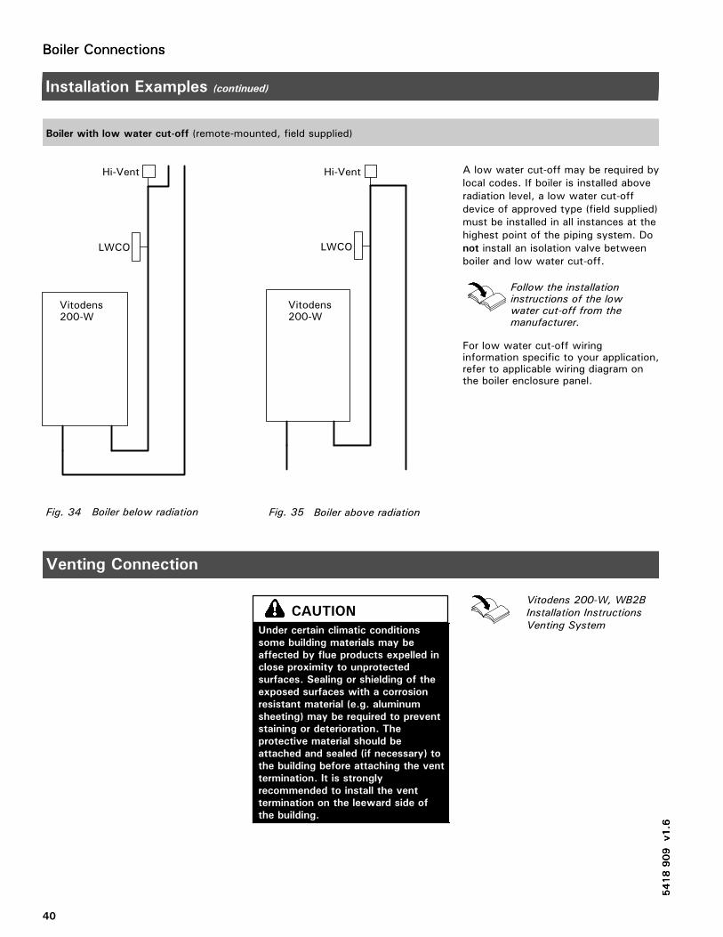
Boiler ConnectionsBoiler Connections
40
Installation Examples (continued)
Boiler with low water cut-off (remote-mounted, field supplied)
A low water cut-off may be required bylocal codes. If boiler is installed aboveradiation level, a low water cut-offdevice of approved type (field supplied)must be installed in all instances at thehighest point of the piping system. Donot install an isolation valve betweenboiler and low water cut-off.
Follow the installationinstructions of the lowwater cut-off from themanufacturer.
For low water cut-off wiringinformation specific to your application,refer to applicable wiring diagram onthe boiler enclosure panel.
Venting Connection
Vitodens 200-W, WB2B
Installation Instructions
Venting System
5418909
v1.6
5418909
v1.6
Boiler below radiation
Vitodens200-W
LWCO
Hi-Vent
Fig. 34 Boiler above radiation
Vitodens200-W
LWCO
Hi-Vent
Fig. 35
5418909
v1.6
Under certain climatic conditions
some building materials may be
affected by flue products expelled in
close proximity to unprotected
surfaces. Sealing or shielding of the
exposed surfaces with a corrosion
resistant material (e.g. aluminum
sheeting) may be required to prevent
staining or deterioration. The
protective material should be
attached and sealed (if necessary) to
the building before attaching the vent
termination. It is strongly
recommended to install the vent
termination on the leeward side of
the building.
CAUTION
Control Connections
41
Electrical Connections
Overview of electrical connections and plug-in connectors
Power supply connection of accessories
The power supply connection of accessories can be made directly at the control.The connection is activated and deactivated with the system on/off switch.The Vitotronic 200-H, HK1M mixing valve control, the mixing valve accessory kitand the Solartrol control require a separate 120 VAC power supply from the wallreceptacle.
Cabling required for:�outdoor temperature sensor�Vitotronic 200-H, HK1M mixing valvecontrol
� accessory kit for heating circuit withmixing valve
� remote switching of operating mode� remote disable� alarm output�wall-mount base� circulating pump
Note on connection of accessories
For details regarding other installation steps required, please reference the
Installation Instructions supplied with the respective accessory part.
Please note that only one accessory part or switch contact can be connected to
the contacts of a plug at a time.
Connecting the Power/Pump module
Installation Instructions
Power/Pump Module
The Vitodens 200-W WB2B boiler isshipped with a Power/Pump Module,which requires a 120 VAC powersupply from a wall receptacle. Themodule contains a 120/230 VACstep-up transformer for 230 VACoperation.
Refer to the Installation Instructionsshipped with the module or thosecontained in this manual for wiringdetails (see page 53).
5418909
v1.6
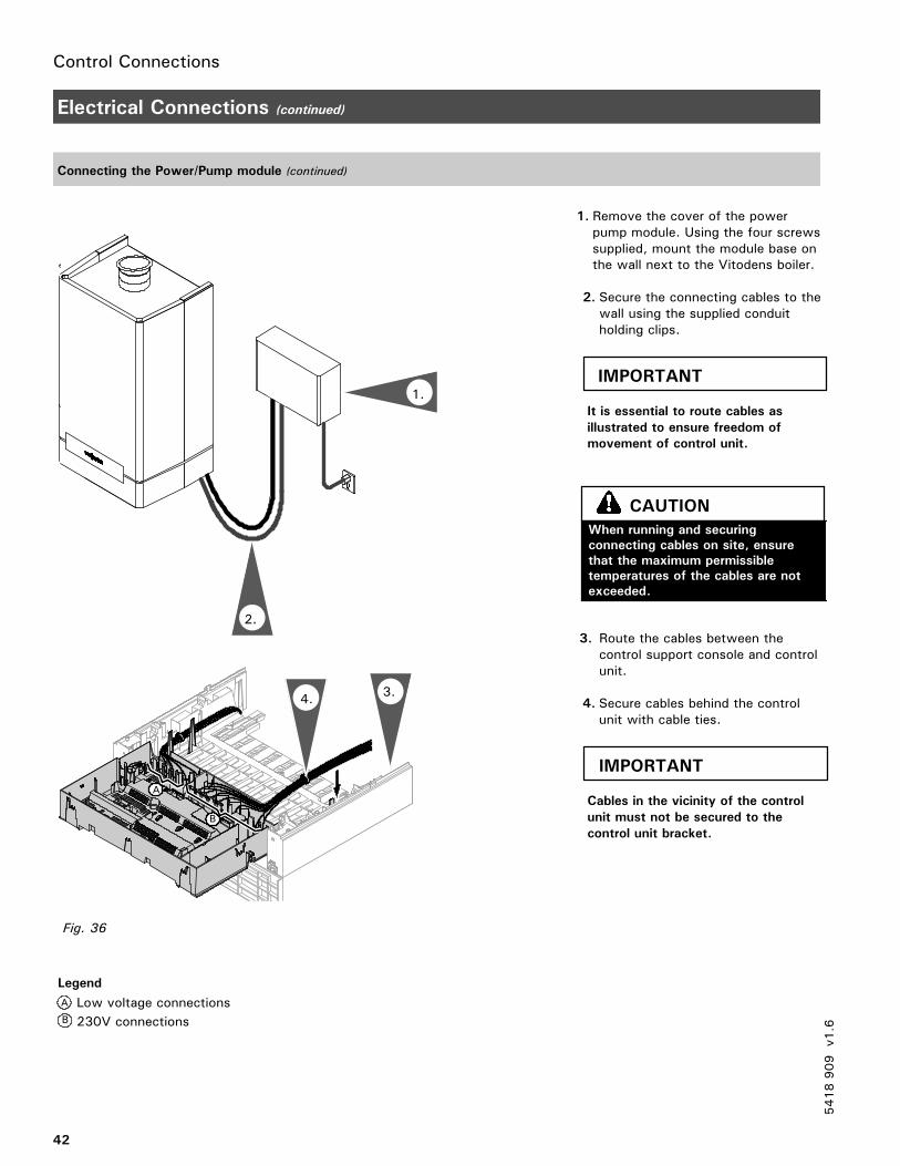
Control Connections
42
Electrical Connections (continued)
Connecting the Power/Pump module (continued)
1. Remove the cover of the powerpump module. Using the four screwssupplied, mount the module base onthe wall next to the Vitodens boiler.
2. Secure the connecting cables to thewall using the supplied conduitholding clips.
It is essential to route cables as
illustrated to ensure freedom of
movement of control unit.
3. Route the cables between thecontrol support console and controlunit.
4. Secure cables behind the controlunit with cable ties.
Cables in the vicinity of the control
unit must not be secured to the
control unit bracket.5418909
v1.6
2.
Low voltage connections
230V connections
A
B
1.
4.3.
Fig. 36
Legend
B
A
IMPORTANT
When running and securing
connecting cables on site, ensure
that the maximum permissible
temperatures of the cables are not
exceeded.
CAUTION
IMPORTANT
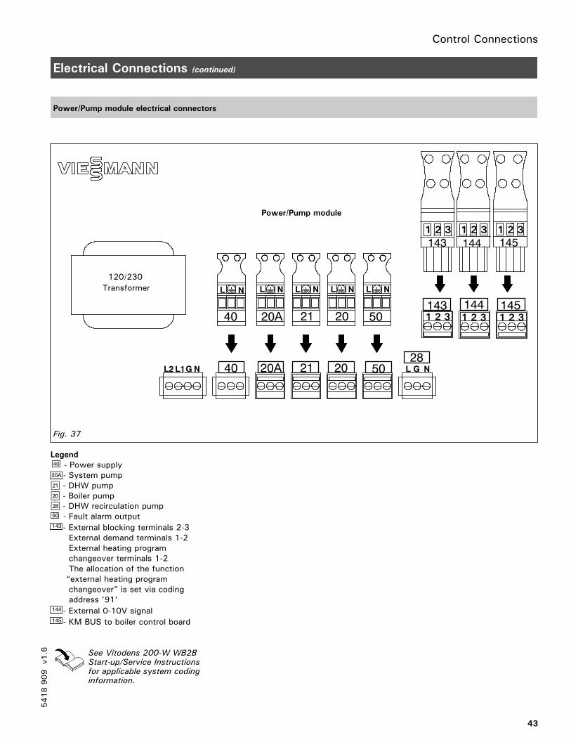
Control Connections
43
Electrical Connections (continued)
Power/Pump module electrical connectors
Legend40 - Power supply20A - System pumpsA - DHW pumpsÖ - Boiler pumpsK - DHW recirculation pump50 - Fault alarm output143 - External blocking terminals 2-3
External demand terminals 1-2External heating programchangeover terminals 1-2The allocation of the function“external heating programchangeover” is set via codingaddress ’91’
144 - External 0-10V signal145 - KM BUS to boiler control board
See Vitodens 200-W WB2BStart-up/Service Instructionsfor applicable system codinginformation.
5418909
v1.6
NL
143
28L G NL2
NLNLNL
L1GN
50202120A40
NL
120/230
Transformer
145144143
Power/Pump module
1 2 3 1 2 3
1 2 3
1 2 3
1451441 2 3 1 2 3
50202120A40
Fig. 37
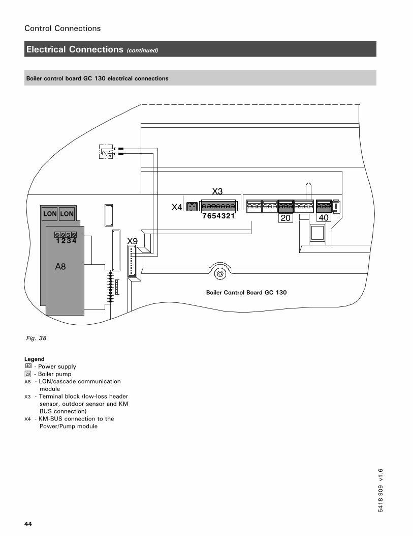
Control Connections
44
Electrical Connections (continued)
Boiler control board GC 130 electrical connections
Legend40 - Power supplysÖ - Boiler pumpA8 - LON/cascade communication
moduleX3 - Terminal block (low-loss header
sensor, outdoor sensor and KMBUS connection)
X4 - KM-BUS connection to thePower/Pump module
5418909
v1.6
A8
201234567
X3
Boiler Control Board GC 130
4321
LON
A8
X4LON
40
Fig. 38
X9
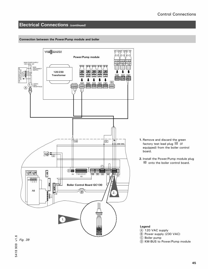
Control Connections
45
Electrical Connections (continued)
Connection between the Power/Pump module and boiler
1. Remove and discard the green
factory test lead plug 40 (ifequipped) from the boiler controlboard.
2. Install the Power/Pump module plug40 onto the boiler control board.
Legend
120 VAC supplyPower supply (230 VAC)Boiler pumpKM-BUS to Power/Pump module
5418909
v1.6
NL
145144143
28L G NL2
NLNLNL
1 2 3 1 2 3 2 3
L1GN
50202120A40
NL120/230
Transformer
145
31 2
144
31 2
143
31 2
409620351001234567X4
X3
5
Boiler Control Board GC130X9.3
X9.4
X
X11
LON
KMK
9
X8
X7
4321X1
LONX2
LONX1
KMK1KMK2
145 20
SAFETYDEVICE
LOWWATERCUT--OFF
120VAC
RECEPTACLEWALL
--TYPICAL
AP2P1
L2L1
SWITCHDISCONNECT
MAIN POWER SUPPLY120V, 60HZ, 12A
N
MAIN
LG
L N
230 VAC
50202120A40
1.
A8
1
Fig. 39
Power/Pump module
2.

Control Connections
46
Electrical Connections (continued)
Accessories electrical connections
See the following pages for connection to the individual accessories.
5418909
v1.6
N
409620351001234567X4X3
L
145 145
5
2
230 VAC
Boiler Control Board GC130X9.3
X9.4
X
X11
LON
KMK
9
X8
X7
LONX2
LONX1
1 20 40
NL
145144143
50202120A
28
L G N40L2
NLNLNL
EXTERNALDEMAND
EXTERNALSIGNAL0--10 V
-- +
120VACM
120VACM
120VACM M
120VAC
120VAC
DHW
RE--CIRC.PUMP
FAULTALARMOUTPUT
BOILERPUMP
DHWPUMP
SYSTEMPUMP
1 2 3 1 2 3 1 2 3
L1 G N
31
2
145
SAFETYDEVICE
LOWWATERCUT--OFF
120VAC
RECEPTACLE
WALL
--TYPICAL
A
P2
P1
L2
L1
SWITCH
DISCONNECT
MAIN POWER SUPPLY
120V, 60HZ, 12A
N
MAIN
LG
31 2
145
31 2
144
31 2
143
50202120A40
NL
Vitotronic200--H
HK1M
LON
120/230
Transformer
Fig. 40
Power/Pump module
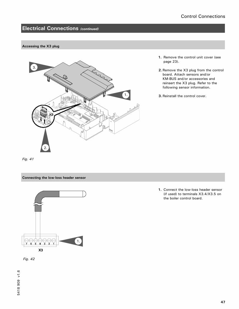
Control Connections
47
Electrical Connections (continued)
Accessing the X3 plug
1. Remove the control unit cover (seepage 23).
2. Remove the X3 plug from the controlboard. Attach sensors and/orKM-BUS and/or accessories andreinsert the X3 plug. Refer to thefollowing sensor information.
3. Reinstall the control cover.
Connecting the low-loss header sensor
1. Connect the low-loss header sensor(if used) to terminals X3.4/X3.5 onthe boiler control board.
5418909
v1.6
X3
Fig. 41
1.
2.
3.
1234567 4
X3
Fig. 42
1.
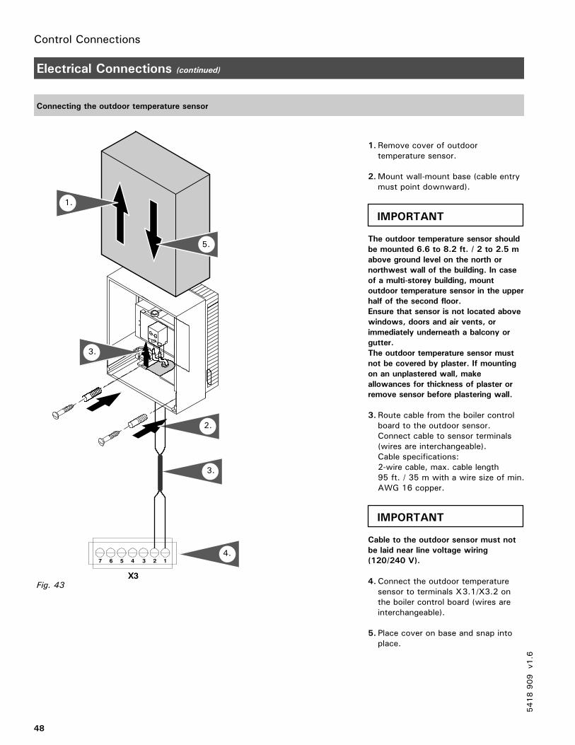
Control Connections
48
Electrical Connections (continued)
Connecting the outdoor temperature sensor
1. Remove cover of outdoortemperature sensor.
2.Mount wall-mount base (cable entrymust point downward).
The outdoor temperature sensor should
be mounted 6.6 to 8.2 ft. / 2 to 2.5 m
above ground level on the north or
northwest wall of the building. In case
of a multi-storey building, mount
outdoor temperature sensor in the upper
half of the second floor.
Ensure that sensor is not located above
windows, doors and air vents, or
immediately underneath a balcony or
gutter.
The outdoor temperature sensor must
not be covered by plaster. If mounting
on an unplastered wall, make
allowances for thickness of plaster or
remove sensor before plastering wall.
3. Route cable from the boiler controlboard to the outdoor sensor.Connect cable to sensor terminals(wires are interchangeable).Cable specifications:2-wire cable, max. cable length95 ft. / 35 m with a wire size of min.AWG 16 copper.
Cable to the outdoor sensor must not
be laid near line voltage wiring
(120/240 V).
4.Connect the outdoor temperaturesensor to terminals X3.1/X3.2 onthe boiler control board (wires areinterchangeable).
5. Place cover on base and snap intoplace.
5418909
v1.6
123567 4
X3
2.
5.
1.
Fig. 43
3.
4.
3.
IMPORTANT
IMPORTANT
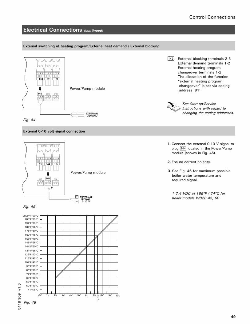
Control Connections
145144
EXTERNALDEMAND
31 2
145
31 2
144
31 2
143
1 2 3 1 2 31 23
143
Power/Pump module
Fig. 44
49
Electrical Connections (continued)
External switching of heating program/External heat demand / External blocking
aVD - External blocking terminals 2-3External demand terminals 1-2External heating programchangeover terminals 1-2The allocation of the function“external heating programchangeover” is set via codingaddress ‘91’
See Start-up/Service
Instructions with regard to
changing the coding addresses.
External 0-10 volt signal connection
1.Connect the external 0-10 V signal toplug aVF located in the Power/Pumpmodule (shown in Fig. 45).
2. Ensure correct polarity.
3. See Fig. 46 for maximum possibleboiler water temperature andrequired signal.
* 7.4 VDC at 165ºF / 74ºC for
boiler models WB2B 45, 60
5418909
v1.6
145144143
EXTERNALSIGNAL0-10 V
31 2
145
31 2
144
31 2
143
12 31 23 1 2 3
+--
+
--
Power/Pump module
Fig. 45
0V 1V 2V 3V 4V 5V 6V 7V 8V 9V 10V
*7.4V
212ºF/100ºC
203ºF/95ºC
194ºF/90ºC
185ºF/85ºC
176ºF/80ºC
158ºF/70ºC
167ºF/75ºC
149ºF/65ºC
122ºF/50ºC
131ºF/55ºC
144ºF/60ºC
104ºF/40ºC
113ºF/45ºC
59ºF/15ºC
77ºF/25ºC
95ºF/35ºC
50ºF/10ºC
68ºF/20ºC
86ºF/30ºC
41ºF/5ºC
Fig. 46
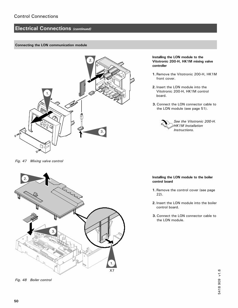
Control Connections
50
Electrical Connections (continued)
Connecting the LON communication module
Installing the LON module to the
Vitotronic 200-H, HK1M mixing valve
controller
1. Remove the Vitotronic 200-H, HK1Mfront cover.
2. Insert the LON module into theVitotronic 200-H, HK1M controlboard.
3. Connect the LON connector cable tothe LON module (see page 51).
See the Vitotronic 200-H.
HK1M Installation
Instructions.
Installing the LON module to the boiler
control board
1. Remove the control cover (see page22).
2. Insert the LON module into the boilercontrol board.
3. Connect the LON connector cable tothe LON module.
5418909
v1.6
1.
2.
3.
Fig. 47 Mixing valve control
2.
1.
3.
X7
Fig. 48 Boiler control
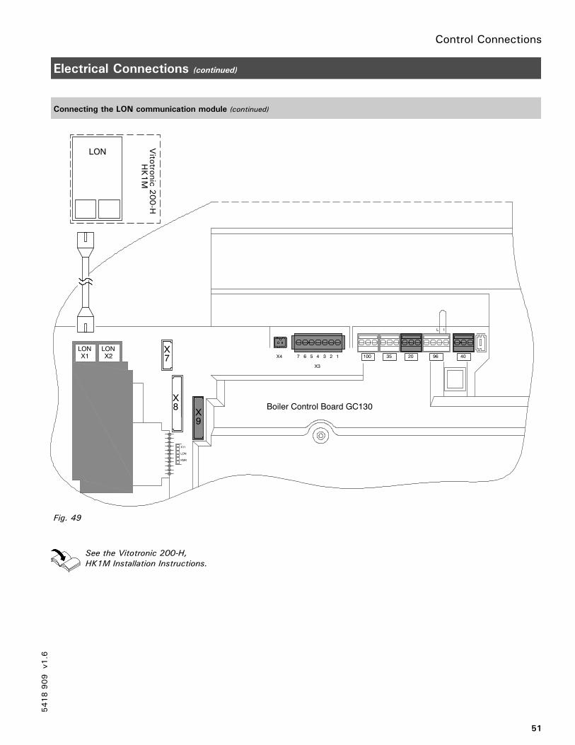
Control Connections
51
Electrical Connections (continued)
Connecting the LON communication module (continued)
See the Vitotronic 200-H,
HK1M Installation Instructions.
5418909
v1.6
409620351001234567X4
X3
L 1
Boiler Control Board GC130X
X11
LON
KMK
9
X8
X7
LONX2
LONX1
Vitotro
nic200-H
HK1M
LON
Fig. 49
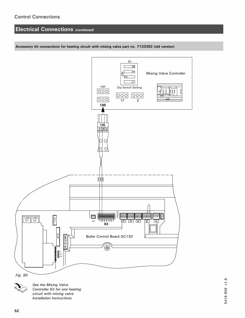
Control Connections
52
Electrical Connections (continued)
Accessory kit connections for heating circuit with mixing valve part no. 7133392 (old version)
See the Mixing Valve
Controller Kit for one heating
circuit with mixing valve
Installation Instructions.
5418909
v1.6
X3
L 1
Boiler Control Board GC130
X11
LON
KMK
X8
X7
LONX2
LONX1
9X
409620351001234567X4
141
145
ON
1
2
3
S1
17 2
4
Mixing Valve Controller
Dip Switch Setting
Fig. 50
145
145
31 2
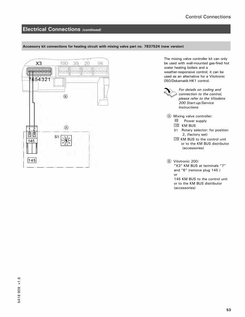
Control Connections
53
Electrical Connections (continued)
Accessory kit connections for heating circuit with mixing valve part no. 7837524 (new version)
The mixing valve controller kit can onlybe used with wall-mounted gas-fired hotwater heating boilers and aweather-responsive control; it can beused as an alternative for a Vitotronic050/Dekamatik-HK1 control.
For details on coding and
connection to the control,
please refer to the Vitodens
200 Start-up/Service
Instructions
A Mixing valve controller:40 Power supply145 KM BUSS1 Rotary selector: for position
2, (factory set)145 KM BUS to the control unit
or to the KM BUS distributor(accessories)
B Vitotronic 200:”X3” KM BUS at terminals ”7”and ”6” (remove plug 145 )or145 KM BUS to the control unitor to the KM BUS distributor(accessories)
5418909
v1.6
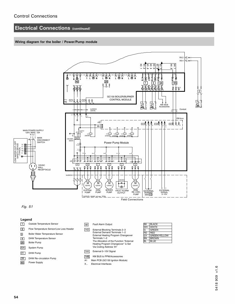
Control Connections
54
Electrical Connections (continued)
Wiring diagram for the boiler / Power/Pump module
5418909
v1.6
REPMUJ
LATOT.xamACAV021:STUPTUO
sub--MK
1X--
N G L
LGN L G NL G N L G NNGL
1FA21T
2K
5K
T
V032--021
AV300
%5-- %5+
2F
1HBCP
2X
LGN
4K
1 231 2 3 12 3
3X
N G
5K
CAV042
NLL G
N G
1 2 3
3K
1K
NGL
61GWAx3
120VAC
M120VAC
M120VAC
M
DISCONNECTSWITCH
A
P1
P2
L2
L1
MAIN
MAIN POWER SUPPLY120V, 60HZ, 12A
N G L
LOWWATERCUT--OFF
SAFETYDEVICE
--TYPICAL
120VACWALLRECEPTACLE
PUMPDHWSYSTEM
PUMPBOILER
PUMP
A1 Main PCB (GC130 Ignition Module)
X... Electrical Interfaces
2K
4K 1K
3K
CDV42 CDV42 CDV42 CDV42
CAV03261GWAx4
System Pump
Outside Temperature Sensor
Flow Temperature Sensor/Low Loss Header
Boiler Water Temperature Sensor
DHW Temperature Sensor
Boiler Pump
DHW Pump
DHW Re--circulation Pump
Power Supply
Fault Alarm Output
KM BUS to PPM/Accessories
External Demand Terminals 1--2
143
External 0--10V Signal144
120VAC
M
DHWRE--CIRC.
-- +
-- +
FAULT ALARMOUTPUT
EXTERNALDEMANDSEE143
EXTERNAL
0--10VSIGNALPUMP
External Heating Program Changeover
Terminals 1--2
The Allocation of the Function ”External
Heating Program Changeover” is Set
Via Coding Address ’91’
40 20A 21 20 50 28
145144143
20A
21
28
40 20
External Blocking Terminals 2--3
X9.3
X9.4
120VAC
1 2 3 4 5 6 7
Conduit
BK BLACK
WH WHITE
G GREEN
RD RED
GY GREEN/YELLOW
KM--BUSAccessories
GC130 BOILER/BURNER
CONTROL MODULE
BN BROWN
BL BLUE
L1 L2
WH GN BK RD
BN BL
Power Pump Module
Field Connections
Fig. 51
Legend
T3.5A
8
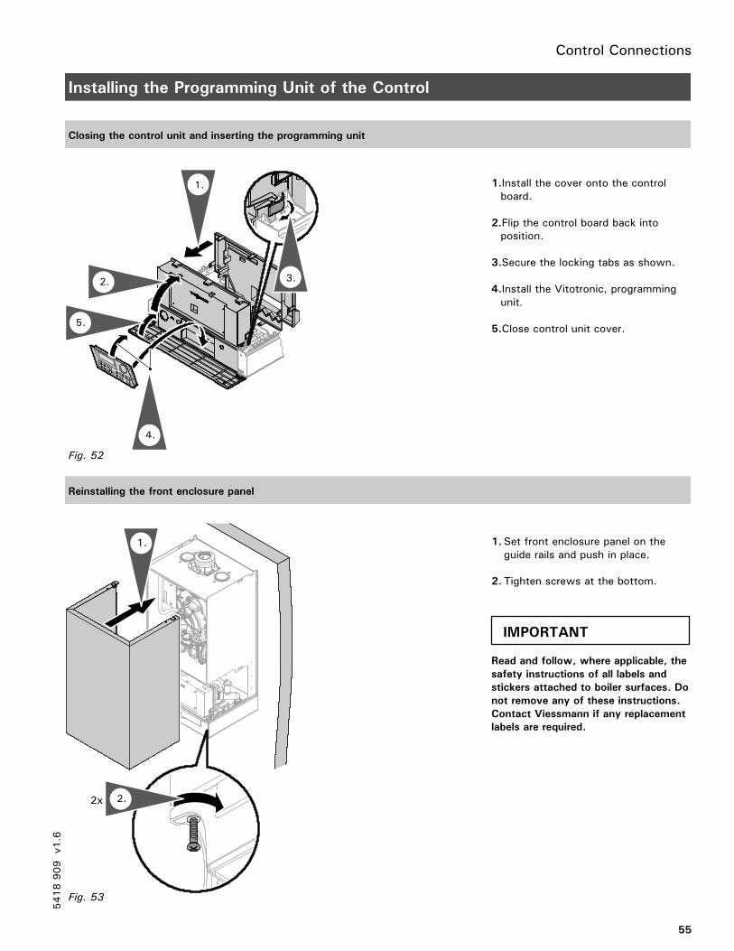
Control Connections
55
Installing the Programming Unit of the Control
Closing the control unit and inserting the programming unit
1.Install the cover onto the controlboard.
2.Flip the control board back intoposition.
3.Secure the locking tabs as shown.
4.Install the Vitotronic, programmingunit.
5.Close control unit cover.
Reinstalling the front enclosure panel
1. Set front enclosure panel on theguide rails and push in place.
2. Tighten screws at the bottom.
Read and follow, where applicable, the
safety instructions of all labels and
stickers attached to boiler surfaces. Do
not remove any of these instructions.
Contact Viessmann if any replacement
labels are required.
5418909
v1.6
2.
1.
5.
4.
3.
Fig. 52
1.
2x
Fig. 53
2.
IMPORTANT
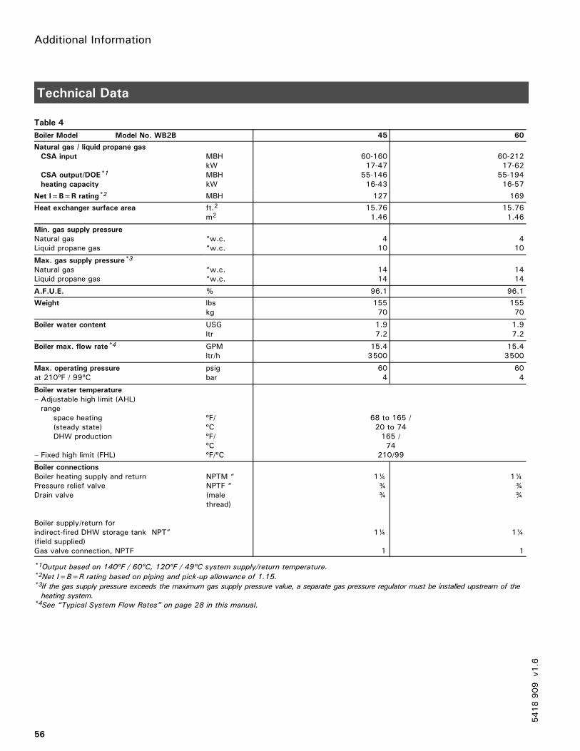
Additional Information
56
Technical Data
Table 4
Boiler Model Model No. WB2B 45 60
Natural gas / liquid propane gas
CSA input
CSA output/DOE*1
heating capacity
MBHkWMBHkW
60-16017-4755-14616-43
60-21217-6255-19416-57
Net I=B=R rating*2 MBH 127 169
Heat exchanger surface area ft.2
m215.761.46
15.761.46
Min. gas supply pressure
Natural gasLiquid propane gas
“w.c.“w.c.
410
410
Max. gas supply pressure*3
Natural gasLiquid propane gas
“w.c.“w.c.
1414
1414
A.F.U.E. % 96.1 96.1
Weight lbskg
15570
15570
Boiler water content USGltr
1.97.2
1.97.2
Boiler max. flow rate*4 GPMltr/h
15.43500
15.43500
Max. operating pressure
at 210ºF / 99ºCpsigbar
604
604
Boiler water temperature
– Adjustable high limit (AHL)range
space heating(steady state)DHW production
– Fixed high limit (FHL)
ºF/ºCºF/ºCºF/ºC
68 to 165 /20 to 74165 /74
210/99
Boiler connections
Boiler heating supply and return NPTM “Pressure relief valve NPTF “Drain valve (male
thread)
Boiler supply/return forindirect-fired DHW storage tank NPT”(field supplied)Gas valve connection, NPTF
1¼¾¾
1¼
1
1¼¾¾
1¼
1
*1Output based on 140ºF / 60ºC, 120ºF / 49ºC system supply/return temperature.*2Net I=B=R rating based on piping and pick-up allowance of 1.15.*3If the gas supply pressure exceeds the maximum gas supply pressure value, a separate gas pressure regulator must be installed upstream of the
heating system.*4See “Typical System Flow Rates” on page 28 in this manual.
5418909
v1.6
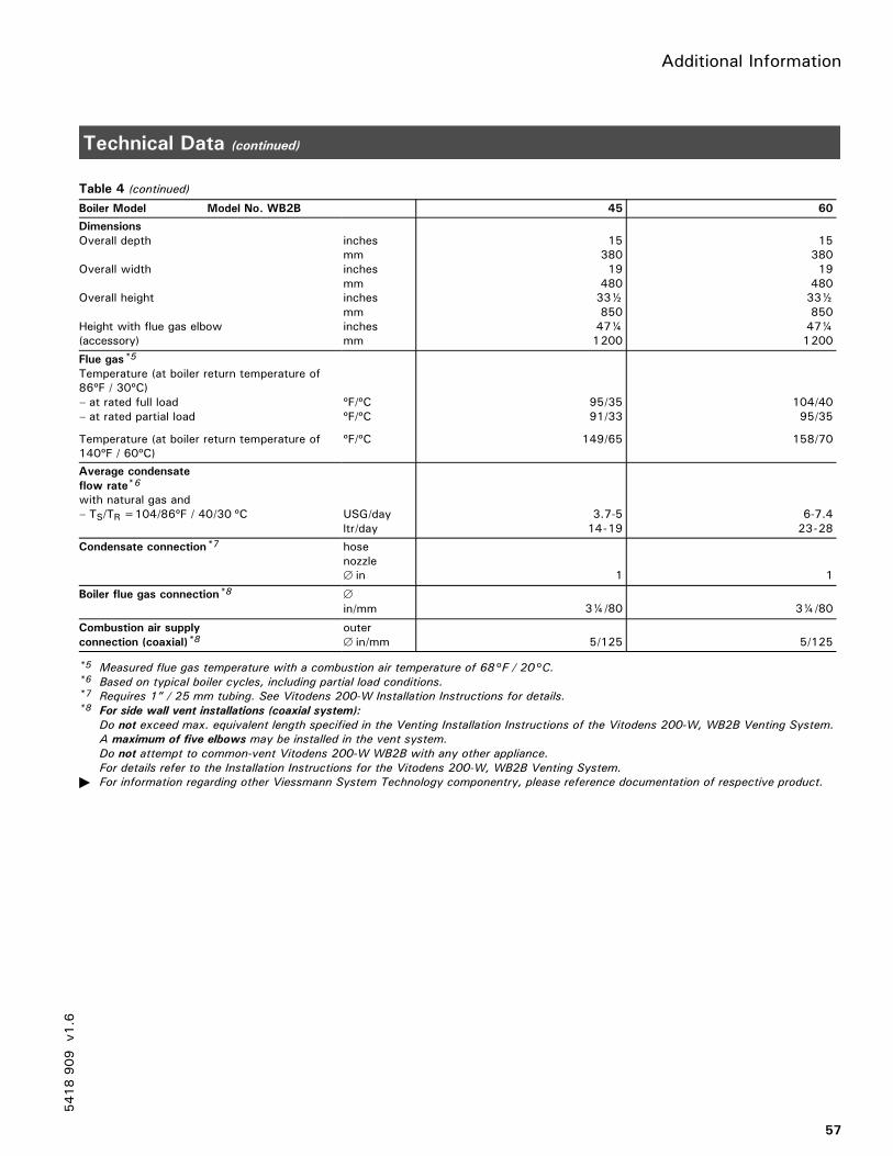
Additional Information
57
Technical Data (continued)
Table 4 (continued)
Boiler Model Model No. WB2B 45 60
Dimensions
Overall depth
Overall width
Overall height
Height with flue gas elbow(accessory)
inchesmminchesmminchesmminchesmm
153801948033½85047¼1200
153801948033½85047¼1200
Flue gas*5
Temperature (at boiler return temperature of86ºF / 30ºC)– at rated full load– at rated partial load
Temperature (at boiler return temperature of140ºF / 60ºC)
ºF/ºCºF/ºC
ºF/ºC
95/3591/33
149/65
104/4095/35
158/70
Average condensate
flow rate*6
with natural gas and– TS/TR=104/86ºF / 40/30 ºC USG/day
ltr/day3.7-514-19
6-7.423-28
Condensate connection*7 hosenozzle∅ in 1 1
Boiler flue gas connection*8 ∅
in/mm 3¼/80 3¼/80
Combustion air supply
connection (coaxial)*8outer∅ in/mm 5/125 5/125
*5 Measured flue gas temperature with a combustion air temperature of 68°F / 20°C.*6 Based on typical boiler cycles, including partial load conditions.*7 Requires 1” / 25 mm tubing. See Vitodens 200-W Installation Instructions for details.*8 For side wall vent installations (coaxial system):
Do not exceed max. equivalent length specified in the Venting Installation Instructions of the Vitodens 200-W, WB2B Venting System.
A maximum of five elbows may be installed in the vent system.
Do not attempt to common-vent Vitodens 200-W WB2B with any other appliance.
For details refer to the Installation Instructions for the Vitodens 200-W, WB2B Venting System.
� For information regarding other Viessmann System Technology componentry, please reference documentation of respective product.
5418909
v1.6
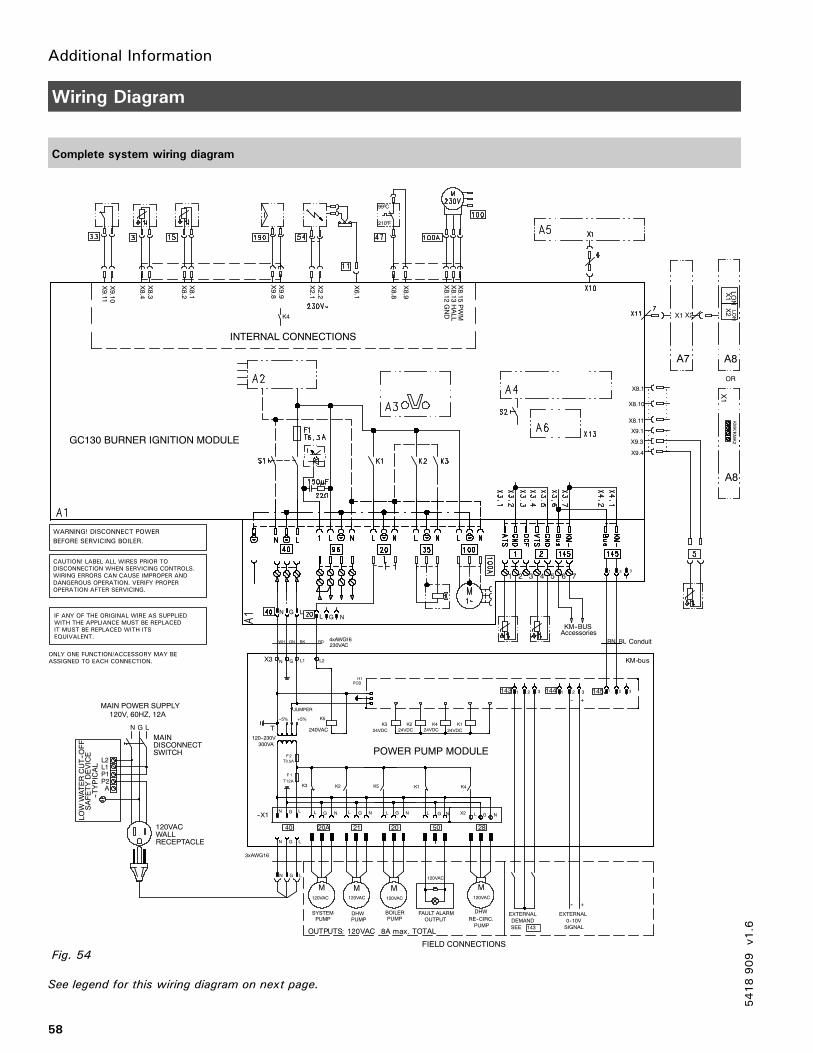
Additional Information
58
Wiring Diagram
Complete system wiring diagram
See legend for this wiring diagram on next page.
5418909
v1.6
N
GL
L
GN L
G
NL GNL GNNGL
T
LGN
1 2 31 2 3 12 3
NNGL
LG
1 2 3
BLBN
N G L
120VAC
M120VAC
M
120VAC
M
DISCONNECTSWITCH
A
P1P2
L2L1
MAIN
MAIN POWER SUPPLY120V, 60HZ, 12A
N G L
LOWWATERCUT--OFF
SAFETYDEVICE
--TYPICAL
120VACWALLRECEPTACLE
PUMPDHWSYSTEM
PUMP
BOILER
PUMP
ONLY ONE FUNCTION/ACCESSORY MAY BEASSIGNED TO EACH CONNECTION.
WARNING! DISCONNECT POWER
CAUTION! LABEL ALL WIRES PRIOR TODISCONNECTION WHEN SERVICING CONTROLS.WIRING ERRORS CAN CAUSE IMPROPER ANDDANGEROUS OPERATION. VERIFY PROPER
IF ANY OF THE ORIGINAL WIRE AS SUPPLIEDWITH THE APPLIANCE MUST BE REPLACEDIT MUST BE REPLACED WITH ITSEQUIVALENT.
BEFORE SERVICING BOILER.
OPERATION AFTER SERVICING.
INTERNAL CONNECTIONS
GC130 BURNER IGNITION MODULE
POWER PUMP MODULE
120VAC
M
DHW
RE--CIRC.
-- +
-- +
FAULT ALARM
OUTPUTEXTERNAL
DEMAND
SEE 143
EXTERNAL
0--10V
SIGNAL
PUMP
99 C
210 F
40 20A 21 20 50 28
145144143
X8.4
X8.3
X8.2
X8.1
X9.8
X9.9
X9.11
X9.10
K4
X8.9
X8.8
X6.1
X2.2
X2.1
X8.15PWM
X8.13HALL
X8.12GND
X8.1
X8.10
X8.11
X9.1
X9.3
X9.4
OR
LON
X1
LON
X2
A7 A8
A8
X1
KMK1KMK2
120VAC
1 2 3 4 5 6 7
Conduit
KM--BUSAccessories
X1 X2
X2--X1
K3 K1K2 K4K5
120--230V
300VA
--5% +5% K5
240VACK1K2K3 K4
24VDC 24VDC24VDC 24VDC
JUMPER
H1PCB
3xAWG16
1F
A21T
2F
T3.5A
FIELD CONNECTIONS
o
o
LATOT.xamA8CAV021:STUPTUO
Fig. 54
CAV03261GWAx4
WH GN BK RD
sub--MKX3 N G L1 L2
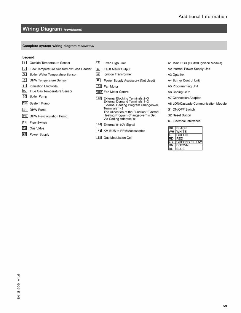
Additional Information
59
Wiring Diagram (continued)
Complete system wiring diagram (continued)
5418909
v1.6
A1 Main PCB (GC130 Ignition Module)
A2 Internal Power Supply Unit
A3 Optolink
A4 Burner Control Unit
A5 Programming Unit
A6 Coding Card
A7 Connection Adapter
A8 LON/Cascade Communication Module
S1 ON/OFF Switch
S2 Reset Button
X.. Electrical Interfaces
System Pump
Outside Temperature Sensor
Flow Temperature Sensor/Low Loss Header
Boiler Water Temperature Sensor
DHW Temperature Sensor
Ionization Electrode
Flue Gas Temperature Sensor
Boiler Pump
DHW Pump
DHW Re--circulation Pump
Flow Switch
Gas Valve
Power Supply
Fixed High Limit
Fault Alarm Output
Ignition Transformer
Power Supply Accessory (Not Used)
Fan Motor
Fan Motor Control
KM BUS to PPM/Accessories
Gas Modulation Coil
External Demand Terminals 1--2143
External 0--10V Signal144
External Heating Program ChangeoverTerminals 1--2The Allocation of the Function ”ExternalHeating Program Changeover” is SetVia Coding Address ’91’
20A
21
28
External Blocking Terminals 2--3
BK BLACKWH WHITEG GREENRD REDGY GREEN/YELLOWBN BROWNBL BLUE
3
20
15
11
5
1
2
Legend
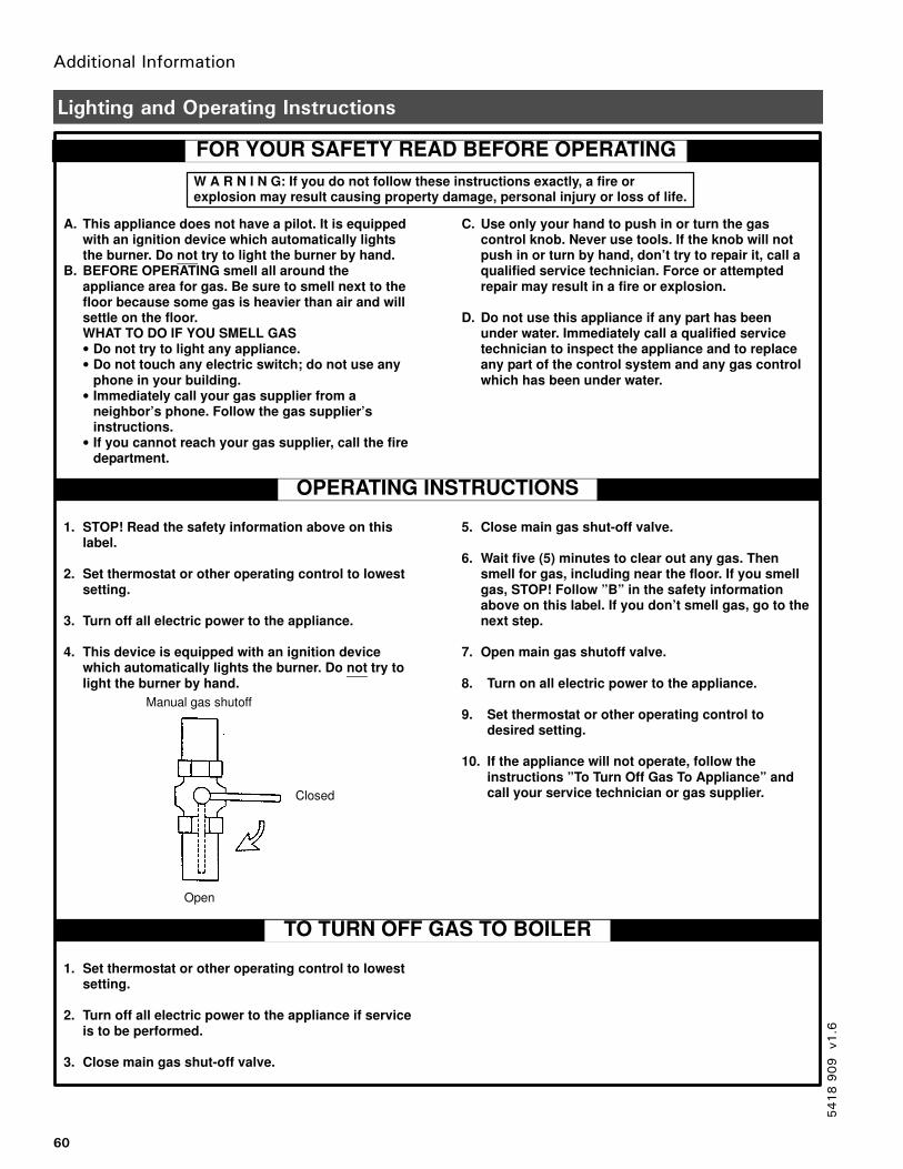
Additional Information
60
Lighting and Operating Instructions
5418909
v1.6
FOR YOUR SAFETY READ BEFORE OPERATING
W A R N I N G: If you do not follow these instructions exactly, a fire orexplosion may result causing property damage, personal injury or loss of life.
A. This appliance does not have a pilot. It is equippedwith an ignition device which automatically lightsthe burner. Do not try to light the burner by hand.
B. BEFORE OPERATING smell all around theappliance area for gas. Be sure to smell next to thefloor because some gas is heavier than air and willsettle on the floor.WHAT TO DO IF YOU SMELL GAS• Do not try to light any appliance.• Do not touch any electric switch; do not use any
phone in your building.• Immediately call your gas supplier from a
neighbor’s phone. Follow the gas supplier’sinstructions.
• If you cannot reach your gas supplier, call the firedepartment.
C. Use only your hand to push in or turn the gascontrol knob. Never use tools. If the knob will notpush in or turn by hand, don’t try to repair it, call aqualified service technician. Force or attemptedrepair may result in a fire or explosion.
D. Do not use this appliance if any part has beenunder water. Immediately call a qualified servicetechnician to inspect the appliance and to replaceany part of the control system and any gas controlwhich has been under water.
1. STOP! Read the safety information above on thislabel.
2. Set thermostat or other operating control to lowestsetting.
3. Turn off all electric power to the appliance.
4. This device is equipped with an ignition devicewhich automatically lights the burner. Do not try tolight the burner by hand.
5. Close main gas shut-off valve.
6. Wait five (5) minutes to clear out any gas. Thensmell for gas, including near the floor. If you smellgas, STOP! Follow ”B” in the safety informationabove on this label. If you don’t smell gas, go to thenext step.
7. Open main gas shutoff valve.
8. Turn on all electric power to the appliance.
9. Set thermostat or other operating control todesired setting.
10. If the appliance will not operate, follow theinstructions ”To Turn Off Gas To Appliance” andcall your service technician or gas supplier.
Manual gas shutoff
Open
Closed
TO TURN OFF GAS TO BOILER
1. Set thermostat or other operating control to lowestsetting.
2. Turn off all electric power to the appliance if serviceis to be performed.
3. Close main gas shut-off valve.
OPERATING INSTRUCTIONS
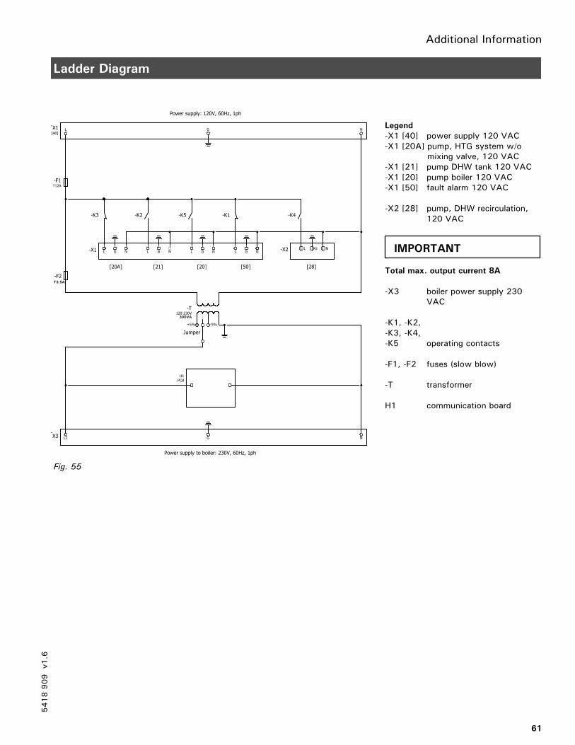
Additional Information
61
Ladder Diagram
Legend
-X1 [40] power supply 120 VAC-X1 [20A] pump, HTG system w/o
mixing valve, 120 VAC-X1 [21] pump DHW tank 120 VAC-X1 [20] pump boiler 120 VAC-X1 [50] fault alarm 120 VAC
-X2 [28] pump, DHW recirculation,120 VAC
Total max. output current 8A
-X3 boiler power supply 230VAC
-K1, -K2,-K3, -K4,-K5 operating contacts
-F1, -F2 fuses (slow blow)
-T transformer
H1 communication board
Fig. 55
T3.5A
300VA
5418909
v1.6
IMPORTANT

62
5418 909 v1.6

63
5418 909 v1.6

Viessmann Manufacturing Company Inc.750 McMurray RoadWaterloo, Ontario • N2V 2G5 • CanadaTel. (519) 885-6300 • Fax (519) 885-0887www.viessmann.ca • [email protected]
Viessmann Manufacturing Company (U.S.) Inc.45 Access RoadWarwick, Rhode Island • 02886 • USATel. (401) 732-0667 • Fax (401) 732-0590www.viessmann-us.com • [email protected]
64
Printedonenvironmentally
friendly
(recycledandrecyclable)paper.
Technicalinformationsubjectto
changewithoutnotice.
5418909
v1.6