Embed Size (px)
Citation preview

Temposonics®
Magnetostrictive, Absolute, Non-contact
Linear-Position Sensors
G-Series Redundant Models GT2 and GT3Analog (Voltage/Current)
Data Sheet
SENSORS
®
Document Part Number 551102 Revision A
All specifications are subject to change. Contact MTS for specifications and engineering drawings that are critical to your application. Drawings contained in this document are for reference only. Go to http://www.mtssensors.com for the latest support documentation and related media.
Time-based Magnetostrictive position sensing principle
Movable position magnet
Magnetic field from position magnet
Interaction of magnetic fields causes waveguide to generate a strain pulse
Magnetic field encompassesentire waveguide - generated
by the interrogation pulse
Bias magnet
Strain-Pulse detector
InterrogationReturn wire
Waveguide
Benefits of Magnetostriction
Temposonics linear-position sensors use the time-based magneto- strictive position sensing principle developed by MTS. Within the sensing element, a sonic-strain pulse is induced in a specially designed magnetostrictive waveguide by the momentary interaction of two magnetic fields. One field comes from a movable permanent magnet that passes along the outside of the sensor. The other field comes from an “interrogation” current pulse applied along the waveguide. The resulting strain pulse travels at sonic speed along the waveguide and is detected at the head of the sensing element.
The position of the magnet is determined with high precision and speed by accurately measuring the elapsed time between the applica-tion of the interrogation pulse and the arrival of the resulting strain pulse with a high-speed counter. The elapsed time measurement is directly proportional to the position of the permanent magnet and is an absolute value. Therefore, the sensor's output signal corresponds to absolute position, instead of incremental, and never requires recalibration or re-homing after a power loss. Absolute, non-contact sensing eliminates wear, and guarantees the best durability and output repeatability.
Model GT3 rod-style redundant position sensor
FEATURES
� Offers Redundancy for Enhanced Safety Applications � Linear, Absolute Measurement � Contains Up to Three Separate, Independent Measuring
Systems in a Single Compact Housing � Non-Contact Sensing Technology � Superior Accuracy, Linearity Deviation Less Than 0.02% � Repeatability Within 0.001% � Fully Adjustable Analog Outputs (Voltage or Current) Within:
-10 to +10 Vdc or 0 to 20 mA
BENEFITS
� Rugged Industrial Sensor � Compact Design with a Standard Size 10 mm (0.39 in.) O.D.
Stainless-Steel Rod � Uses Standard Mounting
APPLICATIONS
� Ideal for High-Safety Applications Requiring Redundancy � Continuous Operation In Harsh Industrial Conditions � High Pressure Conditions
TYPICAL INDUSTRIES
� Power Plants � Water and Wind Turbine Pitch Settings � Marine Propellers � Ship Control Systems � Floodgate Control

MTS SensorsG-Series Redundant, Models GT2/GT3 Temposonics® Linear-Position Sensors - Analog OutputProduct Data Sheet, Document Part No.: 551102, Revision A 04/10, 07/11 2
Product specifications
Product overview
G-Series model GT sensors are extremely robust and are ideal for continuous operation under harsh industrial conditions. The rod housing is capable of withstanding high pressures such as those found in hydraulic cylinders. G-Series redundant sensors provide accurate, linear-position measurement for ap plications that benefit from redundancy due to safety relevant functions.
G-Series Redundant sensors feature two or three independent measuring systems contained in one compact housing. Each measuring system contains its own channel with sensor element, power and evaluation electronics and output signal. Each channel has it's own output connector or cable.
All sensor elements are integrated in one pressure proofed, high-grade steel rod. Rod and housing style feature the approved standard dimensions with 10 mm (0.39 in.) diameter rod and 3/4-16 UNF or M18 x 1.5 threaded hex flanges. The redundant sensor easily installs in applications measuring linear movements of control valves, linear drives, fluid cylinders and machines.
Parameters SpecificationsENVIRONMENTAL
Operating conditions:
Operating temperature:-40 °C (-40 °F) to +75 °C (167 °F)Relative humidity: 90% no condensation
EMC test: Emissions: IEC/EN 61000-6-3Immunity: IEC/EN 61000-6-2IEC/EN 61000-4-2/3/4/5/6/8, level 3/4 criterium A, CE qualified
Shock rating: 100 g (single hit)/IEC standard 68-2-27 (survivability)
Vibration rating: 5 g /10 to 2000 Hz, IEC standard 68-2-6 (operational)
WIRING
Connection type: 6-pin male D60 (M16) connector or integral cable
ROD STYLE SENSOR (MODEL GT2/GT3)
Electronic head: Aluminum housing
Sealing: IP 67
Sensor rod: 304L stainless steel
Operating pressure:
350 bar static, 690 bar peak(5000 psi static, 10,000 psi peak)
Mounting: Any orientation. Threaded flange M18 x 1.5 or 3/4 - 16 UNF-3A
Typicalmounting torque: 45 N-m (33 ft. - lbs.)
Magnet types: Ring magnet, open-ring magnet, or magnet float
Product Overview and Specifications
Parameters SpecificationsOUTPUT
Measured output variables:
Position
Resolution: Analog: Infinite (restricted by output ripple)
Update times: < 1 ms (typical)
Linearity deviation:
< ± 0.02% full stroke (minimum ± 50 µm)
Repeatability: < ± 0.001% of full stroke (minimum ± 2.5 µm)
Hysteresis: < 4 µm
Analog Outputs: Model GT2: 2 output channelsModel GT3: 3 output channels Voltages (Fully adjustable): 0 to 10, 10 to 0, -10 to +10, +10 to -10 Vdc(minimum controller load >5k ohms)Current (Fully Adjustable):4 (0) to 20 mA, 20 to 4 (0) mA(min./max. load 0/500 ohms)
Stroke Length: GT2/GT3:Analog: 50 mm (2 in.) to 2900 mm (1015 in.)
ELECTRONICS
Operatingvoltage:
+24 Vdc nominal: -15 or +20%Polarity protection: up to -30 VdcOvervoltage protection: up to 36 VdcCurrent drain: 100 mA typical per channelDielectric withstand voltage: 500 Vdc(DC ground to machine ground)
Setpoints: Setpoint adjustment (Null/Span):100% of electrical stroke length, 50 mm (2 in.) minimum distance between setpoints.

MTS SensorsG-Series Redundant, Models GT2/GT3 Temposonics® Linear-Position Sensors - Analog Output
Product Data Sheet, Document Part No.: 551102, Revision A 04/10, 07/113
G-Series Models GT2 and GT3 Redundant SensorsOutput and Programming Options
Output options
G-Series rod-style redundant sensors are available with analog (voltage and current) outputs. The G-Series redundant, model GT2 sensor provides two output channels, and model GT3 provides three output channels.
ANALOG (VOLTAGE/CURRENT)
G-Series analog sensors provide direct signals, including voltage (0 to 10 Vdc or -10 to +10 Vdc, foward or reverse acting) and current (4 to 20 mA, or 0 to 20 mA, forward or reverse acting). (see ‘Figure 1’). Both voltage and current outputs allow full adjustments of null and span setpoints (minimum 2 in. between setpoints). Since the outputs are direct, no signal-conditioning elec tronics are needed when interfacing with controllers or meters.
Active stroke length(Measuring range)
Output value
Forward Acting Reverse Acting
Deadzone
Setpoint 1(Null)
Setpoint 2(Span)
To controller, meter or other device:0 to 10 Vdc10 to 0 Vdc
-10 to +10 Vdc+10 to -10 Vdc
4 to 20 mA20 to 4 mA0 to 20 mA20 to 0 mA
Temposonics®
G-Series G®
Figure 1. Single magnet analog output diagram
Advanced communications and programmability
SENSOR FIELD PROGRAMMING AND G-SERIES PC PROGRAMMING KITTemposonics G-Series Redundant sensors are preconfigured at the factory by model code designation. For many applications no adjustments are required for normal sensor installation and operation. If, however, sensor parameter changes are desired while in the field, the G-Series Redundant sensor is easily programmed by using the G-Series PC Programming kit (see 'Figure 2').
Figure 2. G-Series PC Programming Kit, part no. 253311-1
G-Series PC setup software is shipped with the sensor and can also be downloaded from www.mtssensors.com. You can use the PC setup software to configure, diagnose, monitor and program your G-Series sensor in the field without opening the sensor’s electronics housing.
This can simplify installation and commissioning, saving valuable time. Keeping the sensor electronics isolated ensures that seal integrity and the highest product reliability are maintained.
G-Series Analog PC Programming Kit (part no.: 253311-1)includes the following components:
• Wall adapter style power supply (24 Vdc output)• USB Serial converter box with USB cable to connect to PC• Two conection cables:
– Cable for sensor ordered with the D60 integral connector option. – Cable with quick connects for sensor ordered with the integral cable option.• G-Series Analog PC Setup software, on CD-ROM
(for Windows XP or higher)
MTS SensorsG-Series Redundant, Models GT2/GT3 Temposonics® Linear-Position Sensors - Analog OutputProduct Data Sheet, Document Part No.: 551102, Revision A 04/10, 07/11 4
G-Series Models GT2 and GT3 Redundant SensorsMonitoring, Diagnostics and Advanced Programmability
G-Series PC Setup and Configuration Software Interface
VISUAL SOFTWARE INTERFACE The G-Series PC Setup and configuration software provides a user-friendly interface (see ‘Figure 3’) along with the sensor's advanced technology enables the operator to take advantage of the following features:
• Built-in serial interfaces for robust hard-wired serial communication (RS-485).• Remote programmability for operational modes and sensor
parameters (see 'Table 1).
ANALOG (VOLTAGE/CURRENT) OUTPUT FEATURES
Voltage or current output mode
Voltage or current output range
Full adjustment for Null and Span setpoints
Table 1. Remote programmability and operational modes
G-SERIES HANDHELD PROGRAMMER ACCESSORY FOR ANALOG OUTPUT
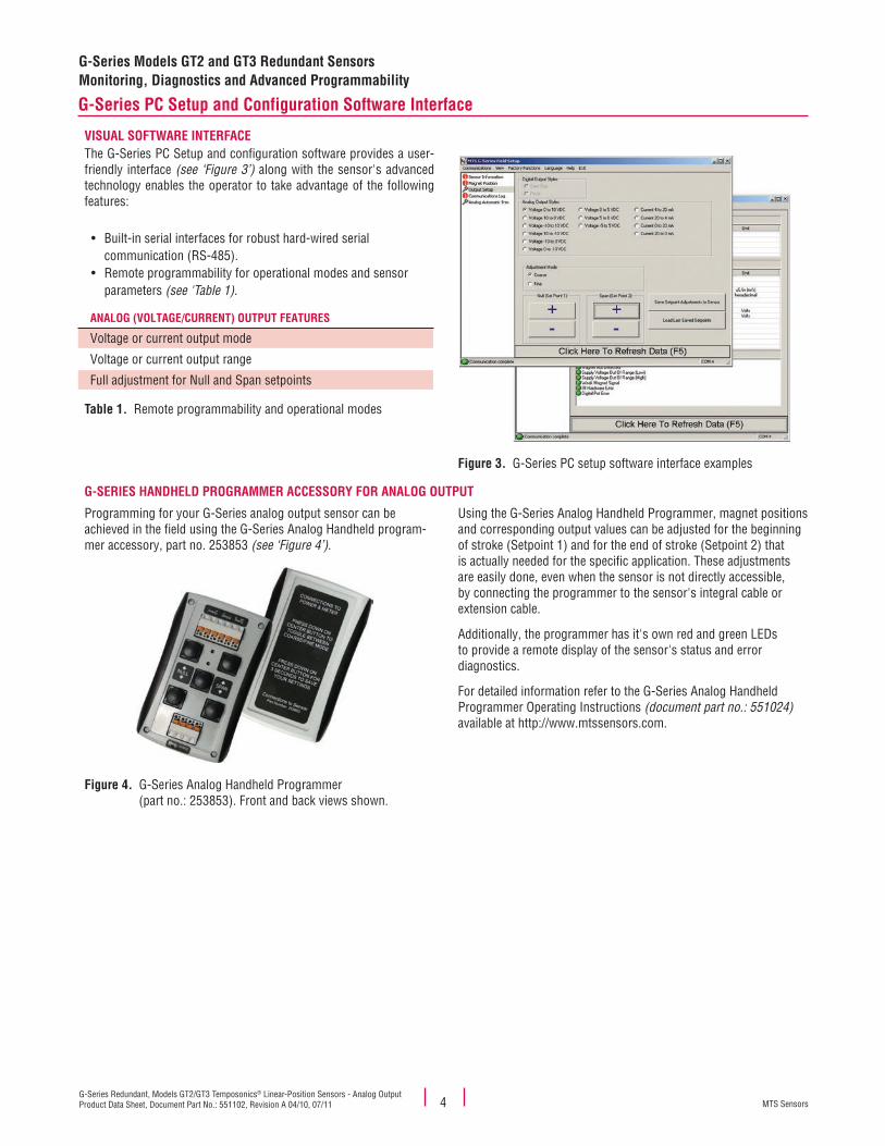
Programming for your G-Series analog output sensor can be achieved in the field using the G-Series Analog Handheld program-mer accessory, part no. 253853 (see ‘Figure 4’).
Figure 4. G-Series Analog Handheld Programmer (part no.: 253853). Front and back views shown.
Using the G-Series Analog Handheld Programmer, magnet positions and corresponding output values can be adjusted for the beginning of stroke (Setpoint 1) and for the end of stroke (Setpoint 2) that is actually needed for the specific application. These adjustments are easily done, even when the sensor is not directly accessible, by connecting the programmer to the sensor's integral cable or extension cable.
Additionally, the programmer has it's own red and green LEDs to provide a remote display of the sensor's status and error diagnostics.
For detailed information refer to the G-Series Analog Handheld Programmer Operating Instructions (document part no.: 551024) available at http://www.mtssensors.com.
Figure 3. G-Series PC setup software interface examples

MTS SensorsG-Series Redundant, Models GT2/GT3 Temposonics® Linear-Position Sensors - Analog Output
Product Data Sheet, Document Part No.: 551102, Revision A 04/10, 07/115
G-Series Models GT2 and GT3 Redundant SensorsDimension References
Models GT2/GT3 rod-style sensor dimension references
Note:
When mounting the sensor, use a basic wrench (see ‘Figure 5') with a maximum 8 mm (0.31 in.) thickness to ensure tightening torque is only applied to the hex flange and not to the electronics housing.
< 8 mm(0.31 in.)
45 N-m(33 ft. - lbs.)
70 mm (2.76 in.)across wrench flats
Figure 5. Basic wrench
Temposonics G-Series rod-style sensors (Models GT2/GT3) offer modular construction, flexible mounting configurations, and easy installa-tion. Models GT2/GT3 sensors are designed for mounting in applications where high pressure conditions exist (5000 psi continuous, 10,000 psi spike), such as inside hydraulic cylinders (see 'Figure 8' on page 7). Both GT2 and GT3 sensor models can also be mounted externally in many applications.
MODEL GT3 ROD-STYLE SENSOR WITH RING MAGNET (MAGNET ORDERED SEPARATELY) Drawing is for reference only, contact applications engineering for tolerance specific information.
D60 integral connector13 mm(0.5 in.)
80 mm(3.2 in.) 51 mm
(2 in.)Stroke length 63.5 mm
(2.5 in.)
3/4 - 16 UNFor
M18 x 1.5
Dead zone
Raised surface36 mm (1.42 in.) dia.0.5 mm (0.02 in.) height
70 mm(2.76 in.)
80 mm(3.15 in.)
O-Ring
Figure 6. Models GT3 Rod-style sensor dimension reference (shown with D60 integral connection type)
MODEL GT3 ROD-STYLE SENSOR WITH INTEGRAL CABLE (MAGNET ORDERED SEPARATELY) Drawing is for reference only, contact applications engineering for tolerance specific information.
Integral cable F_ _ 30 mm(1.2 in.)
80 mm(3.2 in.) 51 mm
(2 in.)63.5 mm(2.5 in.)
Dead zone
3/4 - 16 UNFor
M18 x 1.5
70 mm (2.76 in.)across hex flats
Raised surface36 mm (1.42 in.) dia.0.5 mm (0.02 in.) height
Stroke length
O-Ring
Figure 7. Model GT3 Rod-style sensor dimension reference (shown with integral cable)

MTS SensorsG-Series Redundant, Models GT2/GT3 Temposonics® Linear-Position Sensors - Analog OutputProduct Data Sheet, Document Part No.: 551102, Revision A 04/10, 07/11 6
Standard magnet selections (Models GT2/GT3)
Magnets must be ordered separately with Models GT2/GT3 position sensors. The standard ring magnet (part number 201542-2) is suitable for most applications.
POSITION MAGNET SELECTIONS (Magnet must be ordered separately) (Drawing dimensions are for reference only)
Magnet and magnet dimensions Description Part number
Standard ring magnetI.D.: 13.5 mm (0.53 in.)O.D.: 33 mm (1.3 in.)Thickness: 8 mm (0.3 in.)Operating temperature: - 40 °C to 100 °C
201542-2
Magnet spacer(Non-ferrous, use with ring magnet Part number: 201542-2)I.D.: 14 mm (0.56 in.)O.D.: 32 mm (1.25 in.)Thickness: 3.2 mm (0.125 in.)
400633
Ring magnetI.D.: 13.5 mm (0.53 in.)O.D.: 25.4 mm (1 in.)Thickness: 8 mm (0.3 in.)Operating temperature: - 40 °C to 100 °C
400533
Open-ring magnet, Style MI.D.: 13.5 mm (0.53 in.)O.D.: 33 mm (1.3 in.)Thickness: 8 mm (0.3 in.)Operating temperature: - 40 °C to 100 °C
This magnet may influence the sensor performance specifica-tions for some applications.
251416-2
MAGNET FLOAT SELECTION (Drawing dimensions are for reference only)
Magnet float(Level sensing applications)Specific gravity: 0.70 maximumPressure: 870 psi maximum
(This float is used with Model RH rod-style sensors for hydraulic fluid or fresh water applications only). Collar (part no.: 560777) is recommended for end of stroke stops.
251447
CollarProvides end of stroke stops for magnet float (part no.: 251447) 560777
4 HolesEach 4.3 mm (0.17 in.) dia.90° apart on 24 mm (0.94 in.) dia.
4 HolesEach 4.3 mm (0.17 in.) dia.90° apart on 24 mm (0.94 in.) dia.
21 mm(0.81 in.)
25 mm(0.97 in.)14 mm
(0.55 in.)
2 HolesEach 4.3 mm(0.17 in.) dia. on24 mm (0.94 in.) dia.
60°
14 mm (0.55 in.) Min. I.D.
51 mm (2 in.)Spherical O.D.
3.4 mm (0.13 in.)
CL53 mm(2.1 in.)
27 mm(1.06 in.) OD
10 mm (0.4 in.) ID
5 mm(0.2 in.)
8-32 threads
4 mm(0.16 in.)
8 mm(0.31 in.)
9 mm (0.34 in.)
G-Series Models GT2 and GT3 Redundant SensorsStandard Magnet Selections

MTS SensorsG-Series Redundant, Models GT2/GT3 Temposonics® Linear-Position Sensors - Analog Output
Product Data Sheet, Document Part No.: 551102, Revision A 04/10, 07/117
MG-Series Models GT2 and GT3 Redundant SensorsMounting and Cylinder Installation
Models GT2/GT3 rod-style sensor mountingMODELS GT2/GT3 SENSOR MOUNTING
The position magnet requires minimum distances away from ferrous metals to allow proper sensor output. The minimum distance from the front of the magnet to the cylinder end cap is 15 mm (0.6 in.).
The minimum distance from the back of the magnet to the piston head is 3.2 mm (0.125 in.). However, a minimum distance of at least 5 mm (0.197 in.) is preferred for added performance margin.The non-ferrous spacer (part no.: 400633) provides this minimum distance when used along with the standard ring magnet (part no.: 201542-2), as shown in 'Figure 8'.
Figure 8.
Non ferrous spacer
> 15 mm (0.6 in.)
Min. 3.2 mm (0.125 in.)
Ring magnet
n feracer
mmmm.)
(0.125 in.)
magnetRing m
Nonspa
Min. 3.2 mm
magnetRing m
Cylinder end cap
Piston head
Temposonics ®
G-Series G®
Models GT2/GT3 rod-style mounting
Models GT2/GT3 Rod-Style sensor cylinder installation
When used for direct-stroke measurement in fluid cylinders, the sensor's high pressure, stainless steel rod installs into a bore in the piston head/rod assembly (See 'Figure 9'). This method guarantees a long-life and trouble-free operation.
The sensor’s rod housing and flange installed in the cylinder
Ring magnet
Figure 9. Fluid cylinder installation example

MTS SensorsG-Series Redundant, Models GT2/GT3 Temposonics® Linear-Position Sensors - Analog OutputProduct Data Sheet, Document Part No.: 551102, Revision A 04/10, 07/11 8
G-Series Models GT2 and GT3 Redundant SensorsConnections and Wiring
Models GT2/GT3 connections and wiring
STANDARD MALE (D60) 6-PIN DIN INTEGRAL CONNECTOR (M16)
4536
1 2
Male, 6-pin (D60) integral connector pin-out as viewed from the end of the sensor.
Important Notes:
1. A grounding lug on the end of the sensor is provided for convenient connection to earth ground.2. Appropriate grounding of cable shield is required at the controller end.3. For analog output sensors, the yellow wire (pin 3) and green wire (pin 4) provide serial communications. If possible, during sensor installation these wires should be placed for easy access if future programming or diagnostics are needed. When these wires are not used, they should be isolated with electrical tape to avoid unintended contact with other nearby wires or machine surfaces.
Pin Number Wire Color Function / Analog output
1 Gray 0 to 10, -10 to +10, or 4 to 20 mA, 0 to 20 mA or reverse acting:10 to 0, 10 to -10 Vdc or 20 to 4 mA, 20 to 0 mA
2 Pink Return for pin 1
3 Yellow Programming (RS-485+)
4 Green Programming (RS-485-)
5 Red or Brown Supply voltage (+Vdc)
6 White DC ground (for supply)
CABLE CONNECTOR OPTIONS (FIELD INSTALLABLE) 6-PIN DIN (D60) FEMALE (Drawing dimensions are for reference only)
Connector and connector dimensions Description Part number
Cable Connector, Female, Straight Exit (Field installable)
6-Pin DIN (D60)Mates with standard male (M16) integralconnector
560700
Cable Connector, Female, 90° Exit (Field installable)
6-Pin DIN (D60)Mates with standard male (M16) integralconnector
560778
18 mm(0.7 in.) dia.
54 mm(2.1 in.)
54 mm(2.1 in.)
37 mm(1.5 in)
18 mm(0.7 in.) dia.

MTS SensorsG-Series Redundant, Models GT2/GT3 Temposonics® Linear-Position Sensors - Analog Output
Product Data Sheet, Document Part No.: 551102, Revision A 04/10, 07/119
MG-Series Models GT2 and GT3 Redundant SensorsOrdering Information, Extension Cables
SENSOR CONNECTION TYPES = D 1 - 2
D6 = Female connector, straight exit (part no. 560700), and PVC jacket cable (part no. 530026)
DA = Female connector, 90° exit (part no. 560788), and PVC jacket cable (part no. 530026)
DJ = Female connector, straight exit (part no. 560700), and black polyurethane jacket cable (part no. 530052)
DK = Female connector, 90° exit (part no. 560788), and black polyurethane jacket cable (part no. 530052)
CABLE LENGTHS = 3 - 5
For standard length cables up to 100 ft
005 = 5 ft
015 = 15 ft
025 = 25 ft
050 = 50 ft
100 = 100 ft
For custom length cables over 100 ft— — — = Cable length (maximum cable length is dependent on the output selected; consult MTS Applications Engineering)
CABLE TERMINATION = 6 - 8
P0 = Pigtail cable without connector (2 digit code)
D6M = D6 male connector (straight exit). Only available with the D6 option above.D6F = D6 female connector, straight exit. Only available with the D6 option above.DAF = D6 female connector, 90° exit. Only available with the DA option above.
D
1 2 3 4 5 6 7 8
EXTENSION CABLE WITH CONNECTORS FOR D6 (D60) CONNECTION TYPESExtension Cable and Connector Description Connection type
Female Connector, Straight Exit with Standard PVC Jacket Cable
(Assembly Includes D6 Connector, Part No.: 560700 and Cable, Part No.:530026)
D6
Female Connector, 90° Exit with Standard PVC Jacket Cable
(Assembly Includes D6 Connector, Part No.: 560778 and Cable, Part No.:530026)
DA
Female Connector, Straight Exit with Black Polyurethane Jacket Cable (for higher resistance to moisture, oil and cold temperatures)
(Assembly Includes D6 Connector, Part No.: 560700 and Cable, Part No.:530052)
DJ
Female Connector, 90° Exit with Black Polyurethane Jacket Cable (for higher resistance to moisture, oil and cold temperatures)
(Assembly Includes D6 Connector, Part No.: 560778 and Cable, Part No.:530052)
DK
Ordering Information - Extension Cable with Connector for D6 (D60) Connection Types

SENSORS
®
MTS and Temposonics are registered trademarks of MTS Systems Corporation.All other trademarks are the property of their respective owners.
Printed in USA. Copyright © 2011 MTS Systems Corporation. All Rights Reserved in all media.
Document Part Number: 551102, Revision A 04/10, 07/11
MTS Systems CorporationSensors Division
3001 Sheldon DriveCary, North Carolina27513, USATel.: +1-800-633-7609Fax: +1-919-677-2343 +1-800-498-4442e-mail: [email protected]://www.mtssensors.com
MTS Sensor TechnologieGmbH & Co. KG
Auf dem Schüffel 9D - 58513 Lüdenscheid, GermanyTel.: +49-2351-9587-0Fax: +49-2351-56491e-mail: [email protected]://www.mtssensor.de
MTS Sensors TechnologyCorporation
737 Aihara-cho, Machida-shiTokyo 194-0211, JapanTel.: +81-42-775-3838Fax: +81-42-775-5516e-mail: [email protected]://www.mtssensor.co.jp
Models GT2 and GT3 SensorsOrdering Information
G
1 2 3 4 5 6 7 8 9 10 11 12 13 14 15
SENSOR MODEL = G T 1-3GT2 = Double-redundant rod-style sensor
GT3 = Triple-redundant rod-style sensor
HOUSING STYLE = 4
Model GT rod-style sensor (magnet(s) must be ordered separately):S = US customary threads and pressure
tube, standardM = Metric threads and pressure tube,
standard
STROKE LENGTH = 5-9
— — — — M = Millimeters(Encode in 5 mm increments)
Stroke Length Note:
— — — . — U = Inches and tenths(Encode in 0.1 in. increments)
Rod-style sensor (model GT) stroke range = 50 mm (2 in.) - 2900 mm (115 in.)
CONNECTION TYPE = 10-12
Integral connector:D60 = 6-pin DIN (M16), male, standard (2X or 3X)
Integral cables:F — — = Integral cable, black polyurethane jacket with pigtail termination (2X or 3X) Cable Length Note:
MTS recommends the maximum integral cable length to be 10 meters (33 ft.). Cables greater than 10 m (33 ft.) in length are available, however, proper care must be taken during handling and installation.
Cable length: Encode in feet if using US customary stroke lengthEncode in meters if using metric stroke length
> — — = 3 (03) to 98 (98) ft. or 1 (01) to 30 (30) meters.
INPUT VOLTAGE = 131 = +24 Vdc (+20% - 15%)
OUTPUT = 14-15
V0 = 0 to +10 Vdc A0 = 4 to 20 mANote:
Standard factory settings configure all outputs to be the same per the output option selected (when configuring the model number). If needed, an output can be individually repro-grammed in the field to best fit the application.
V1 = +10 to 0 Vdc A1 = 20 to 4 mAV2 = -10 to +10 Vdc A2 = 0 to 20 mAV3 = +10 to -10 Vdc A3 = 20 to 0 mA