Embed Size (px)
Citation preview
15640 (supersedes 5628)-0613-S4
RTC-8080 IILink‐Belt Cranes
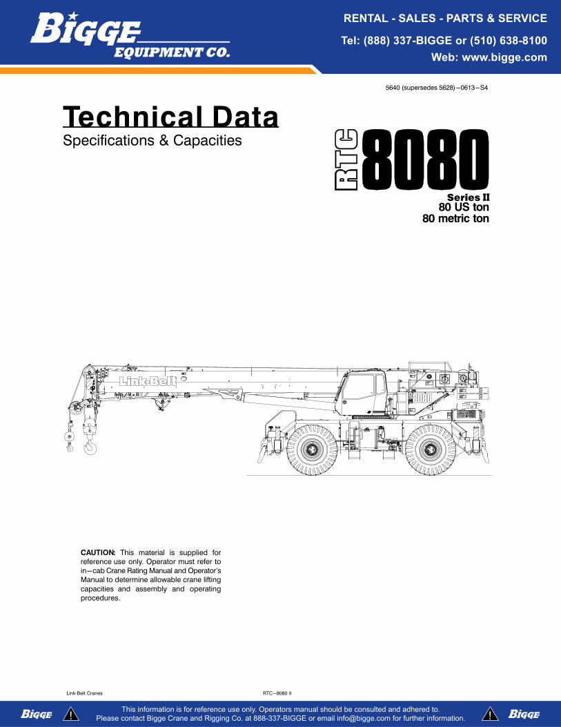
Technical DataSpecifications & Capacities
80 US ton80 metric ton
CAUTION: This material is supplied for
reference use only. Operator must refer to
in-cab Crane Rating Manual and Operator's
Manual to determine allowable crane lifting
capacities and assembly and operating
procedures.

5640 (supersedes 5628)-0613-S4
RTC-8080 II Link‐Belt Cranes

5640 (supersedes 5628)-0613-S4
RTC-8080 IILink‐Belt Cranes
Table Of ContentsBoom, Attachments, and Upper Structure 1. . . . . . . . . . . . . . . . . . . . . . . . . . . . . . . . . . . . . . . . . . . . . . . . . . . .
Boom 1. . . . . . . . . . . . . . . . . . . . . . . . . . . . . . . . . . . . . . . . . . . . . . . . . . . . . . . . . . . . . . . . . . . . . . . . . . . . . . . . . . . .
Boom 1. . . . . . . . . . . . . . . . . . . . . . . . . . . . . . . . . . . . . . . . . . . . . . . . . . . . . . . . . . . . . . . . . . . . . . . . . . . . . . . . . . .
Boom Wear Pads 1. . . . . . . . . . . . . . . . . . . . . . . . . . . . . . . . . . . . . . . . . . . . . . . . . . . . . . . . . . . . . . . . . . . . . . . . .
Boom Head 1. . . . . . . . . . . . . . . . . . . . . . . . . . . . . . . . . . . . . . . . . . . . . . . . . . . . . . . . . . . . . . . . . . . . . . . . . . . . .
Boom Elevation 1. . . . . . . . . . . . . . . . . . . . . . . . . . . . . . . . . . . . . . . . . . . . . . . . . . . . . . . . . . . . . . . . . . . . . . . . . .
Auxiliary Lifting Sheave - Optional 1. . . . . . . . . . . . . . . . . . . . . . . . . . . . . . . . . . . . . . . . . . . . . . . . . . . . . . . . .
Hook Blocks and Balls - Optional 1. . . . . . . . . . . . . . . . . . . . . . . . . . . . . . . . . . . . . . . . . . . . . . . . . . . . . . . . . .
Fly - Optional 1. . . . . . . . . . . . . . . . . . . . . . . . . . . . . . . . . . . . . . . . . . . . . . . . . . . . . . . . . . . . . . . . . . . . . . . . . . .
Fly Extensions - Optional 1. . . . . . . . . . . . . . . . . . . . . . . . . . . . . . . . . . . . . . . . . . . . . . . . . . . . . . . . . . . . . . . . .
Operator's Cab and Controls 2. . . . . . . . . . . . . . . . . . . . . . . . . . . . . . . . . . . . . . . . . . . . . . . . . . . . . . . . . . . . . . . .
Swing 3. . . . . . . . . . . . . . . . . . . . . . . . . . . . . . . . . . . . . . . . . . . . . . . . . . . . . . . . . . . . . . . . . . . . . . . . . . . . . . . . . . . .
Electrical 3. . . . . . . . . . . . . . . . . . . . . . . . . . . . . . . . . . . . . . . . . . . . . . . . . . . . . . . . . . . . . . . . . . . . . . . . . . . . . . . . .
Load Hoist System 4. . . . . . . . . . . . . . . . . . . . . . . . . . . . . . . . . . . . . . . . . . . . . . . . . . . . . . . . . . . . . . . . . . . . . . . . .
Load Hoist Performance 4. . . . . . . . . . . . . . . . . . . . . . . . . . . . . . . . . . . . . . . . . . . . . . . . . . . . . . . . . . . . . . . . . . .
2M Main and Optional Auxiliary Winches 4. . . . . . . . . . . . . . . . . . . . . . . . . . . . . . . . . . . . . . . . . . . . . . . . . . . .
Hydraulic System 4. . . . . . . . . . . . . . . . . . . . . . . . . . . . . . . . . . . . . . . . . . . . . . . . . . . . . . . . . . . . . . . . . . . . . . . . . .
Counterweight 4. . . . . . . . . . . . . . . . . . . . . . . . . . . . . . . . . . . . . . . . . . . . . . . . . . . . . . . . . . . . . . . . . . . . . . . . . . . .
Carrier 5. . . . . . . . . . . . . . . . . . . . . . . . . . . . . . . . . . . . . . . . . . . . . . . . . . . . . . . . . . . . . . . . . . . . . . . . . . . . . . . . . . . .
General 5. . . . . . . . . . . . . . . . . . . . . . . . . . . . . . . . . . . . . . . . . . . . . . . . . . . . . . . . . . . . . . . . . . . . . . . . . . . . . . . . . . .
Outriggers 5. . . . . . . . . . . . . . . . . . . . . . . . . . . . . . . . . . . . . . . . . . . . . . . . . . . . . . . . . . . . . . . . . . . . . . . . . . . . . . . .
Steering and Axles 5. . . . . . . . . . . . . . . . . . . . . . . . . . . . . . . . . . . . . . . . . . . . . . . . . . . . . . . . . . . . . . . . . . . . . . . . .
Suspension 5. . . . . . . . . . . . . . . . . . . . . . . . . . . . . . . . . . . . . . . . . . . . . . . . . . . . . . . . . . . . . . . . . . . . . . . . . . . . . . .
Tires and Wheels 5. . . . . . . . . . . . . . . . . . . . . . . . . . . . . . . . . . . . . . . . . . . . . . . . . . . . . . . . . . . . . . . . . . . . . . . . . .
Brakes 5. . . . . . . . . . . . . . . . . . . . . . . . . . . . . . . . . . . . . . . . . . . . . . . . . . . . . . . . . . . . . . . . . . . . . . . . . . . . . . . . . . .
Electrical 5. . . . . . . . . . . . . . . . . . . . . . . . . . . . . . . . . . . . . . . . . . . . . . . . . . . . . . . . . . . . . . . . . . . . . . . . . . . . . . . . .
Engine 5. . . . . . . . . . . . . . . . . . . . . . . . . . . . . . . . . . . . . . . . . . . . . . . . . . . . . . . . . . . . . . . . . . . . . . . . . . . . . . . . . . .
Transmission 5. . . . . . . . . . . . . . . . . . . . . . . . . . . . . . . . . . . . . . . . . . . . . . . . . . . . . . . . . . . . . . . . . . . . . . . . . . . . . .
Carrier Speeds and Gradeability 6. . . . . . . . . . . . . . . . . . . . . . . . . . . . . . . . . . . . . . . . . . . . . . . . . . . . . . . . . . . . .
Fuel Tank 6. . . . . . . . . . . . . . . . . . . . . . . . . . . . . . . . . . . . . . . . . . . . . . . . . . . . . . . . . . . . . . . . . . . . . . . . . . . . . . . . .
Hydraulic System 6. . . . . . . . . . . . . . . . . . . . . . . . . . . . . . . . . . . . . . . . . . . . . . . . . . . . . . . . . . . . . . . . . . . . . . . . . .
Pump Drive 6. . . . . . . . . . . . . . . . . . . . . . . . . . . . . . . . . . . . . . . . . . . . . . . . . . . . . . . . . . . . . . . . . . . . . . . . . . . . . . .
Axle Loads 7. . . . . . . . . . . . . . . . . . . . . . . . . . . . . . . . . . . . . . . . . . . . . . . . . . . . . . . . . . . . . . . . . . . . . . . . . . . . . . . .
General Dimensions 8. . . . . . . . . . . . . . . . . . . . . . . . . . . . . . . . . . . . . . . . . . . . . . . . . . . . . . . . . . . . . . . . . . . . . . . .
Main Boom Working Range Diagram - Standard 9. . . . . . . . . . . . . . . . . . . . . . . . . . . . . . . . . . . . . . . . . . . . .
Main Boom Lift Capacity Charts - Standard 10. . . . . . . . . . . . . . . . . . . . . . . . . . . . . . . . . . . . . . . . . . . . . . . . .
19,200 lb Counterweight - Fully Extended Outriggers - 360° Rotation 10. . . . . . . . . . . . . . . . . . . . . . . . . . .
Fly Attachment Lift Capacity Charts - Optional 11. . . . . . . . . . . . . . . . . . . . . . . . . . . . . . . . . . . . . . . . . . . . . . .
19,200 lb Counterweight - Fully Extended Outriggers - 360° Rotation 11. . . . . . . . . . . . . . . . . . . . . . . . . . .
Main Boom Working Range Diagram - Metric 13. . . . . . . . . . . . . . . . . . . . . . . . . . . . . . . . . . . . . . . . . . . . . . . .
Main Boom Lift Capacity Charts - Metric 14. . . . . . . . . . . . . . . . . . . . . . . . . . . . . . . . . . . . . . . . . . . . . . . . . . . .
8 709kg Counterweight - Fully Extended Outriggers - 360° Rotation 14. . . . . . . . . . . . . . . . . . . . . . . . . . . .
Fly Attachment Lift Capacity Charts - Optional 15. . . . . . . . . . . . . . . . . . . . . . . . . . . . . . . . . . . . . . . . . . . . . . .
8 709kg Counterweight - Fully Extended Outriggers - 360° Rotation 15. . . . . . . . . . . . . . . . . . . . . . . . . . . .

5640 (supersedes 5628)-0613-S4
RTC-8080 II Link‐Belt Cranes
This Page Intentionally Blank
15640 (supersedes 5628)-0613-S4
RTC-8080 IILink‐Belt Cranes
Boom, Attachments, and Upper Structure� BoomDesign - Four section, formed construction of extra hightensile steel consisting of one base section and Three telescoping sections. The two plate design of each section
has multiple longitudinal bends for superior strength.
Boom� 41-127 ft (12.5-38.7m) four section boom� Two boom extend modes (A-max and standard), con
trolled from the operator's cab, provide superior capaci
ties by varying the extension of the telescoping sections:� A-max extends to 69.7 ft (21.2m)� Standard extends to 127 ft (38.7m)
� Mechanical boom angle indicator� Maximum tip height for each extend mode is:� A-max is 80.3 ft (24.5m)� Standard is 136.7 ft (41.7m)
Boom Wear Pads� Wear pads with Teflon inserts that self-lubricate the
boom sections� Bottom wear pads are universal for all boom sections,
except for tip section� Top wear pads are universal for all boom sections
Boom Head� Five 16.5 in (41.9cm) root diameter nylon sheaves to han
dle up to ten parts of line� Easily removable wire rope guards� Rope dead end lugs on each side of the boom head� Boom head is designed for quick-reeve of the hook
block
Boom Elevation� One double acting hydraulic cylinder with integral hold
ing valve� Boom elevation: -3° to 80°
Auxiliary Lifting Sheave - Optional� Single 16.5 in (41.9m) root diameter nylon sheave� Easily removable wire rope guards� Does not affect erection of the fly or use of the main head
sheaves
Hook Blocks and Balls - Optional� 40 ton (36.3mt) 4 sheave quick-reeve hook block with
safety latch� 60 ton (54.4mt) 4 sheave quick-reeve hook block with
safety latch� 80 ton (72.5mt) 5 sheave quick-reeve hook block with
safety latch� 8.5 ton (7.7mt) swivel and non-swivel hook balls with
safety latch� 10 ton (9.1mt) swivel and non-swivel hook balls with
safety latch
Fly - Optional� 38 ft (11.6m) one piece lattice fly, stowable, offsettable to
2°, 15°, 30°, and 45°. Maximum tip height is 174.3 ft(53.1m).
� 38-64 ft (11.6-19.5m) two piece bi-fold lattice fly, stowable, offsettable to 2°, 15°, 30°, and 45°. Maximum tipheight is 199.7 ft (60.9m).
� 10-38-64 ft (3.0-11.6-19.5m) three piece bi-fold lattice fly, stowable, offsettable 2°, 15°, 30°, and 45°. Maximum tip height is 199.7 ft (60.9m).
Fly Extensions - Optional� One 16 ft (4.9m) lattice extension, equipped with two 16.5
in (41.9cm) root diameter nylon sheaves, to be mountedbetween the boom head and fly options. Maximum tipheight is 215.2 ft (65.6m).
� Two 16 ft (4.9m) lattice extensions, one equipped with two16.5 in (41.9cm) root diameter nylon sheaves, to bemounted between the boom head and fly options. Maximum tip height is 230.9 ft (70.4m). Minimum of 19,200 lb (8709kg) of counterweight required.
2 5640 (supersedes 5628)-0613-S4
RTC-8080 II Link‐Belt Cranes
� Operator's Cab and ControlsEnvironmental Cab - Fully enclosed, one person cab ofgalvaneal steel structure with acoustical insulationEquipped with:� Tinted and tempered glass windows� Extra-large fixed front window with windshield wiper and
washer� Swing up roof window with windshield wiper and washer� Sliding left side door with large fixed window� Sliding rear and right side windows for ventilation� Six way adjustable, cushioned seat with seat belt and
storage compartment� Diesel fired warm-water heater with air ducts for front
windshield defroster and cab floor� Defroster fan for the front window� Bubble level� Circulating fan� Adjustable sun visor� Dome light� Cup holder� Fire extinguisher� Left side viewing mirror� Two position travel swing lock
Air Conditioning - Optional - Integral with cab heatingsystem utilizing the same ventilation outlets
Engine Dependant Warm-Water Heater - Optional -With air ducts for front windshield defroster and cab floor
Steering Column - Pedestal type with tilt and telescopefunctions for operator comfort. Column includes the following controls and indicators:
Left and right levers include:� Horn button� Turn signal switch� Driving light switch� Transmission direction switch
Panel mounted switches for:� Travel park brake� Steer mode selector� 2/4 wheel drive/range selector� Transmission gear selector� Hazard flasher
Panel mounted indicator/warning lights for:� Transmission temperature� Travel park brake� Service brake� Turn signals� Rear wheel offset� Emergency steer - optional
Armrest Controls - Two dual axis hydraulic joystick controllers or optional single axis hydraulic controllers for:� Cab heater and A/C Controls� Swing� Boom hoist� Main rear winch� Auxiliary front winch - optional� Drum rotation indication� Drum rotation indicator activation switch� Winch high/low speed and disable switch(es)� Warning horn button� Swing park brake� Engine throttle lock
Outrigger Controls - Hand held control box with umbilicalcord gives the operator the freedom to view operation whilesetting the outriggers.
Foot Controls� Boom telescope� Swing brake� Engine throttle� Service brake
Right Front Console - Controls and indicators for:� Engine ignition � 12 volt power connections� Engine throttle lock � E-stop switch� Function disable � Ignition switch on indicator� Front windshield wiper light
and washer � Boom floodlight - optional� Cab floodlights � Rotating beacon/Strobe� Warning horn light - optional� Console dimmer switch � Third wrap set and activate� Bubble level switches - optional� Emergency engine shutdown

35640 (supersedes 5628)-0613-S4
RTC-8080 IILink‐Belt Cranes
Cab Instrumentation - Ergonomically positioned, analoginstrumentation for crane operation including:� Tachometer � Swing park brake light� Engine water temperature � Engine speed� Fuel level � Engine oil pressure� Hydraulic oil temperature � Battery voltage� Stop engine � Fuel rate (gal/hr)� Check engine � Engine load� Wait to start � Engine Diagnostics� DPF regeneration light(1)
� DPF regeneration inhibit switch(1)
� DPF regeneration initiate switch(1)
� High exhaust temperature light(1)
� Regeneration disabled light(1)
Diagnostic Center - Located behind the operator's seat.� Engine diagnostic� RCL CANBUS diagnostic� Crane Controller USB diagnostic� RCL controller USB diagnostic
LinkBelt Pulse – The LinkBelt inhouse designed, totalcrane operating system that utilizes the display as areadout and operator interface for the following systems:� Rated capacity limiter – LCD graphic audio – visual
warning system integrated into the dash with anti – twoblock and function limiter. Operating data includes:� Crane configuration� Boom length and angle
� Boom head height� Allowed load and % of allowed load� RCL light bar
� Boom angle� Radius of load� Actual load
� Wind speed� Highlighted unit of measurement on working screen� Telescope operation displayed in real time
� Counterweight installation/removal� Third wrap indicator� Diagnostics
� Operator settable alarms (include):• Maximum and minimum boom angles• Maximum tip height
• Maximum boom length• Swing left/right positions• Operator defined area (imaginary plane)
(1) (Tier 4i / Stage IIIB engine only)
Integrated Third Wrap Indicator - Optional - Link‐BeltPulse color display visually and audibly warns the operatorwhen the wire rope is on the first/bottom layer and when
the wire rope is down to the last three wraps.
Integrated Third Wrap Function Kickout - Optional -Link-Belt Pulse color display visually and audibly warnsthe operator when the wire rope is on the first/bottom layer
and provides a function kickout when the wire rope is downto the last three wraps.
Internal RCL Light Bar - Optional - Visually informs theoperator when crane is approaching maximum load capacity with a series of green, yellow, and red lights.
External RCL Light Bar - Optional - Visually informs theground crew when crane is approaching maximum loadcapacity with a series of green, yellow, and red lights.
� SwingMotor/Planetary - Bi-directional hydraulic swing motormounted to a planetary reducer for 360° continuoussmooth swing at 1.9 rpm
Swing Park Brake - 360°, electric over hydraulic, (springapplied/hydraulic released) multi-disc brake mounted onthe speed reducer. Operated by a switch from the operator's cab.
Swing Brake - 360°, foot operated, hydraulic applied discbrake mounted to the speed reducer
Swing Lock - Two-position swing lock (boom over frontor rear) operated from the operator's cab
360° Positive Swing Lock - Optional - Meets New YorkCity requirement
� ElectricalSwing Alarm - Audio warning device signals when theupper is swinging.
Lights� Two working lights on front of the cab� One rotating amber beacon on top of the cab - optional� One amber strobe beacon on top of the cab - optional� Boom floodlight - Single- optional� Boom floodlight - Dual- optional� Boom floodlight - High intensity remote controlled- op
tional
4 5640 (supersedes 5628)-0613-S4
RTC-8080 II Link‐Belt Cranes
� Load Hoist SystemLoad Hoist Performance
Main (Front) and Auxiliary (Rear) Winches - 3/4 in (19mm) Rope
Maximum Line Pull Normal Line Speed High Line Speed Layer Total
Layer lb kN ft/min m/min ft/min m/min ft m ft m
1 18,500 82.29 172 52.4 341 103.9 114 34.7 114 34.7
2 17,071 75.94 187 57.0 371 113.1 124 37.8 238 72.5
3 15,798 70.27 202 61.6 401 122.2 134 40.8 372 113.4
4 14,701 65.39 217 66.1 430 131.1 144 43.9 516 157.3
5 13,747 61.15 232 70.7 460 140.2 154 46.9 670 204.2
6 164 50.0 834 254.2
Wire Rope Application in mm Type lb kN
Main (Rear) Winch
Standard 3/4 19 18x19 rotation resistant - right regular lay (Type RB) 12,920 57.47
Optional 3/4 19 4 strand, low torque, right regular lay (Type GC) 22,400 99.64
Optional 3/4 19 34x7 rotation resistant - right regular lay (Type ZB) 15,600 69.39
Auxiliary (Front)Winch
Standard 3/4 19 18x19 rotation resistant - right regular lay (Type RB) 12,920 57.47
Optional 3/4 19 4 strand, low torque, right regular lay (Type GC) 22,400 99.64
Optional 3/4 19 34x7 rotation resistant - right regular lay (Type ZB) 15,600 69.39
2M Main and Optional Auxiliary Winches� Axial piston, full and half displacement (2-speed) motors
driven through planetary reduction unit for positive control under all load conditions.
� Grooved lagging� Power up/down mode of operation� Hoist drum cable follower - optional� Drum rotation indicator� Drum diameter: 16 in (40.6cm)� Rope length:� Main: 670 ft (204.2m)� Auxiliary: 500 ft (152.4m) or 670 ft (204.2m)
� Maximum rope storage: 834 ft (254.2m)� Terminator style socket and wedge
� Hydraulic SystemCounterbalance Valves - All hoist motors, boom extendcylinders, and boom hoist cylinders are equipped withcounterbalance valves to provide load lowering and prevents accidental load drop when hydraulic power is suddenly reduced.
Hydraulic Oil Coolers - One carrier mounted cooler removes heat from the hydraulic oil. Remote mounted onright side of the carrier.
� CounterweightStandard - Total of 19,200 lb (8 709.0kg) counterweightconsisting of two counterweights pinned to the upper withcapacities for:
� 0 lb (0kg) counterweight*� 9,600 lb (4 354kg) counterweight� 19,200 lb (8 709.0kg) counterweight
* Travel speed limited to 5 mph.
Optional - Hydraulic counterweight removal activatedby a hand-held controller with enough cable to access
the pins on each side of the counterweights.
55640 (supersedes 5628)-0613-S4
RTC-8080 IILink‐Belt Cranes
Carrier
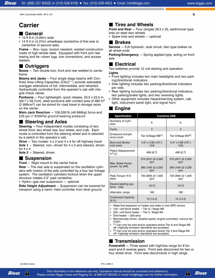
� General� 10 ft 9 in (3.28m) wide� 14 ft 4 in (4.37m) wheelbase (centerline of first axle to
centerline of second axle)
Frame - Box-type, torsion resistant, welded constructionmade of high tensile steel. Equipped with front and reartowing and tie-down lugs, tow connections, and accessladders.
� OutriggersBoxes - Two double box, front and rear welded to carrierframe
Beams and Jacks - Four single stage beams with Confined Area Lifting Capacities (CALC�) provide selectableoutrigger extensions of full, intermediate, and retracted.Hydraulically controlled from the operator's cab with integral check valves.
Pontoons - Four lightweight, quick release, 23.5 x 23.5 in(59.7 x 59.7cm), steel pontoons with contact area of 460 in2
(2 968cm2) can be stored for road travel in storage rackson the carrier.
Main Jack Reaction - 108,000 lb (48 988kg) force and235 psi (1 620kPa) ground bearing pressure
� Steering and AxlesSteering - Four independent modes consisting of twowheel front, two wheel rear, four wheel, and crab. Eachmode is controlled from the steering wheel and is selectedby a switch in the operator's cab.
Drive - Two modes: 4 x 2 and 4 x 4 for off highway travelAxle 1 - Steered, non-driven for 4 x 2 and steered, drivenfor 4 x 4Axle 2 - Steered, driven
� SuspensionFront - Rigid mount to the carrier frame
Rear - The rear axle is suspended on the oscillation cylinders with motion of the axle controlled by a four bar linkagesystem. The oscillation cylinders lockout when the upperstructure rotates 2.5° past centerline.� Hydro-gas rear suspension - optional
Ride Height Adjustment - Suspension can be lowered fortransport using a hand-held controller from level ground.
� Tires and WheelsFront and Rear - Four (single) 29.5 x 25, earthmover typetires on steel disc wheels� Spare tires and wheels - optional
� BrakesService - Full hydraulic, dual circuit, disc type brakes onall wheel ends
Parking/Emergency - Spring applied type, acting on frontaxle
� ElectricalTwo batteries provide 12 volt starting and operation
Lights� Front lighting includes two main headlights and two park
ing/directional indicators.� Side lighting includes two parking/directional indicators
per side.� Rear lighting includes two parking/directional indicators,
two parking/brake lights, and two reversing lights.� Other equipment includes hazard/warning system, cab
light, instrument panel light, and signal horn.
� Engine
Specification Cummins QSB
Numbers of Cylinders
6 6
Cycle 4 4
Emissions Compliance Level:
Tier 4i/Stage IIIB(1) Tier 3/Stage IIIA(2)
Bore and Stroke:inch (mm)
4.21 x 4.88 (107 x124)
4.21 x 4.88 (107 x124)
Piston Displacement:in3 (L)
408 (6.7) 408 (6.7)
Max. Brake Horsepower: hp (kW)
270 (201) @ 2,000rpm
270 (201) @ 2,000rpm
260 (194) @ 2,200rpm
260 (194) @ 2,200rpm
Peak Torque: ft lb(Nm)
730 (990) @ 1,500rpm
730 (990) @ 1,500rpm
Electric/starting systems: volts
12/12 12/12
Alternator: amps 160 160
Crankcase Capacity:qt (L)
15 (14.2) 15 (14.2)
� Water/fuel separator w/ heater and water in fuel (WIF) sensor
� 120-volt block heater - Tier 4i / Stage IIIB
� 220-volt block heater - Tier 3 / Stage IIIA
� Grid heater - 200 amp
� Mechanically driven, variable speed, engine controlled, viscous fanclutch
� (1) Can only be sold and/or operated where Tier 4i and Stage IIIBoff-highway emission standards are accepted.
� (2) Can only be sold and/or operated where Tier 3 and Stage IIIAoff-highway emission standards are accepted.
� TransmissionPowershift - Three speed with high/low range for 6 forward and 6 reverse gears. Front axle disconnect for two orfour wheel drive. Front axle disconnects in high range.
6 5640 (supersedes 5628)-0613-S4
RTC-8080 II Link‐Belt Cranes
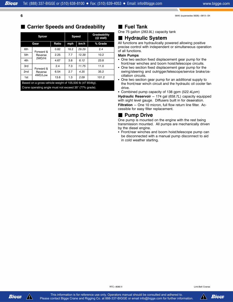
� Carrier Speeds and Gradeability
Spicer SpeedGradeability
(@ stall)
Gear Ratio mph km/h % Grade
6thForward &Reverse2WD/Hi
0.82 18.2 29.29 2.4
5th 2.25 7.7 12.39 10.2
4th 4.67 3.8 6.12 23.8
3rdForward &Reverse
4WD/Low
2.4 7.3 11.75 11.0
2nd 6.54 2.7 4.35 35.2
1st 13.6 1.3 2.09 101.2
Based on a gross vehicle weight of 105,500 lb (47 854kg).
Crane operating angle must not exceed 35° (77% grade).
� Fuel TankOne 75 gallon (283.9L) capacity tank
� Hydraulic SystemAll functions are hydraulically powered allowing positiveprecise control with independent or simultaneous operationof all functions.
Main Pumps� One two section fixed displacement gear pump for the
front/rear winches and boom hoist/telescope circuits.� One two section fixed displacement gear pump for the
swing/steering and outrigger/telescope/service brake/oscillation circuits.
� One two section gear pump for an additional supply tothe front/rear winch circuit and the hydraulic oil cooler fandrive.
� Combined pump capacity of 138 gpm (522.4Lpm)
Hydraulic Reservoir - 174 gal (658.7L) capacity equippedwith sight level gauge. Diffusers built in for deaeration.
Filtration - One 10 micron, full flow return line filter. Accessible for easy filter replacement.
� Pump DriveOne pump is mounted on the engine with the rest beingtransmission mounted. All pumps are mechanically drivenby the diesel engine.� Front/rear winches and boom hoist/telescope pump can
be disconnected with a manual pump disconnect to aidin cold weather starting.

75640 (supersedes 5628)-0613-S4
RTC-8080 IILink‐Belt Cranes
Axle Loads
Base crane with zerocounterweight and full tank of fuel
Gross VehicleWeight (1)
Upper Facing Front Upper Facing Rear
Front Axles Rear Axles Front Axles Rear Axles
lb kg lb kg lb kg lb kg lb kg
Tier 4i/Stage IIIB
81,125 36 798 52,515 23 820 28,610 12 977 21,959 9 960 59,166 26 837
Tier 3/Stage IIIA
80,992 36 737 52,573 23 847 28,419 12 891 22,017 9 987 58,975 26 751
Pintle hook, front 13 6 17 8 -5 -2 17 8 -5 -2
Pintle hook, rear 13 6 -5 -2 18 8 -5 -2 18 8
Hydro-gas suspension 56 25 20 9 36 16 20 9 36 16
Operator in cab 250 113 140 64 110 50 110 50 140 64
Hoist drum follower - main 69 31 -24 -11 93 42 93 42 -24 -11
Auxiliary winch with 500 ft (152.4m) wire rope 616 279 -75 -34 691 313 691 313 -75 -34
Hoist drum follower - auxiliary 69 31 -6 -3 75 34 75 34 -6 -3
Substitute 500 ft (152.4m) wire rope with 670 ft(204.2m) - auxiliary
213 97 -7 -3 220 100 220 100 -7 -3
Remove 670 ft (202.4m) wire rope from rear(main) winch
-856 -388 187 85 -1,043 -473 -1,043 -473 187 85
Remove 500 ft (152.4m) wire rope from front(auxiliary) winch
-643 -292 21 10 -664 -301 -664 -301 21 10
Counterweight removal 300 136 -89 -40 389 176 389 176 -89 -40
One slab of counterweight on upper 9,600 4 355 -3,356 -1 522 12,956 5 877 12,956 5 877 -3,356 -1 522
Two slabs of counterweight on upper 19,200 8 709 -6,712 -3 045 25,912 11 754 25,912 11 754 -6,712 -3 045
Emergency steering 258 117 40 18 218 99 218 99 40 18
360° mechanical swing lock 140 64 72 33 68 31 68 31 72 33
Air conditioning 128 58 37 17 91 87 91 87 37 17
Floodlight to front of boom base section 11 5 15 7 -4 -2 -4 -2 15 7
Fly mounting brackets to boom base section forfly options
225 102 306 39 -81 -37 -81 -37 306 139
38 ft (11.6m) offsettable fly - stowed 1,659 753 2,895 1 313 -1,236 -561 -1,236 -561 2,895 1 313
38-64 ft (11.6-19.5m) offsettable fly - stowed 2,401 1 089 3,888 1 764 -1,487 -675 -1,487 -675 3,888 1 764
10-38-64 ft (3.0-11.6-19.5m) offsettable fly -stowed
2,762 1 253 4,728 2 145 -1,966 -892 -1,966 -892 4,728 2 145
Auxiliary lifting sheave 110 50 327 148 -217 -98 -217 -98 327 148
80 ton (72.5mt) 5-sheave hook block at bumper 1,406 638 2,134 968 -728 -330 -728 -330 2,134 968
60 ton (54.4mt) 4-sheave hook block at bumper 1,109 503 1,683 763 -574 -260 -574 -260 1,683 763
10 ton (9.1mt) hook ball at bumper 583 264 885 401 -302 -137 -302 -137 885 401
8.5 ton (7.7mt) hook ball at bumper 360 163 546 248 -186 -84 -186 -84 546 248
80 ton (72.5mt) 5-sheave hook block at boomhead
1,406 638 4,031 1 828 -2,625 -1 191 -2,625 -1 191 4,031 1 828
60 ton (54.4mt) 4-sheave hook block at boomhead
1,109 503 3,180 1 442 -2,071 -939 -2,071 -939 3,180 1 442
10 ton (9.1mt) hook ball at boom head 583 264 1,672 758 -1,089 -494 -1 089 -494 672 758
8.5 ton (7.7mt) hook ball at boom head 360 163 1,032 468 -672 -305 -672 -305 1,032 468
Tire Maximum Allowable Axle Load @ 20 mph (32.2km/h)
29.5 x 25 (28-PR) 55,000 lb (24 948kg)
(1) Adjust gross vehicle weight and axle loading according to component weight.Note: All weights are ±3%.
8 5640 (supersedes 5628)-0613-S4
RTC-8080 II Link‐Belt Cranes
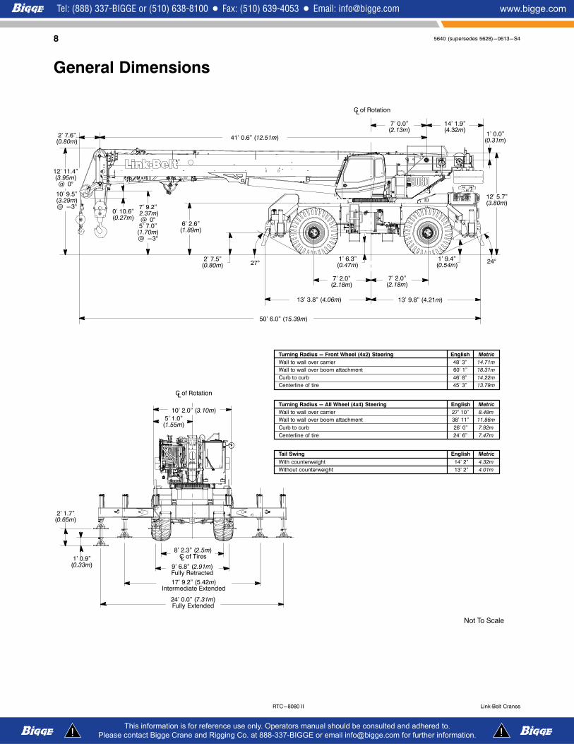
General Dimensions
8' 2.3” (2.5m)C of TiresL
2' 7.5”(0.80m)
24°27°
Not To Scale
Turning Radius - Front Wheel (4x2) Steering English Metric
Wall to wall over carrier 48' 3” 14.71m
Wall to wall over boom attachment 60' 1” 18.31m
Curb to curb 46' 8” 14.22m
Centerline of tire 45' 3” 13.79m
Tail Swing English Metric
With counterweight 14' 2” 4.32m
Turning Radius - All Wheel (4x4) Steering English Metric
Wall to wall over carrier 27' 10” 8.48m
Wall to wall over boom attachment 38' 11” 11.86m
Curb to curb 26' 0” 7.92m
Centerline of tire 24' 6” 7.47m
Without counterweight 13' 2” 4.01m
C of RotationL
41' 0.6” (12.51m)
7' 0.0”(2.13m)
1' 0.0”(0.31m)
12' 5.7”(3.80m)
1' 6.3”(0.47m)
13' 3.8” (4.06m)
7' 2.0”(2.18m)
13' 9.8” (4.21m)
1' 9.4”(0.54m)
6' 2.6”(1.89m)
7' 9.2”(2.37m)
@ 0°5' 7.0”
(1.70m)@ -3°
2' 7.6”(0.80m)
1' 0.9”(0.33m)
2' 1.7”(0.65m)
C of RotationL
24' 0.0” (7.31m)Fully Extended
17' 9.2” (5.42m)Intermediate Extended
9' 6.8” (2.91m)Fully Retracted
5' 1.0”(1.55m)
50' 6.0” (15.39m)
7' 2.0”(2.18m)
0' 10.6”(0.27m)
12' 11.4”(3.95m)
@ 0°
14' 1.9”(4.32m)
10' 2.0” (3.10m)
10' 9.5”(3.29m)@ -3°
95640 (supersedes 5628)-0613-S4
RTC-8080 IILink‐Belt Cranes
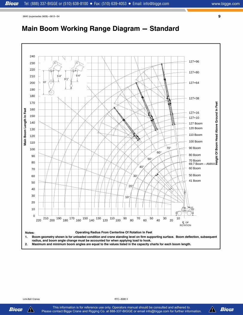
Main Boom Working Range Diagram - Standard
Notes:
1. Boom geometry shown is for unloaded condition and crane standing level on firm supporting surface. Boom deflection, subsequent
radius, and boom angle change must be accounted for when applying load to hook.
2. Maximum and minimum boom angles are equal to the values listed in the capacity charts for each boom length.
70�60�
50�
40�
30�
20�
10�
Main
Bo
om
Len
gth
In
Fe
et
Heig
ht
Of
Bo
om
Head
Ab
ove G
rou
nd
In
Fe
et
Operating Radius From Centerline Of Rotation In Feet
41 Boom
50 Boom60
70
80
90
100
110
120
130
140
150
160
170
180
190
200
210
127+96
127+80
127+64
127+38
127+16
127+10
127 Boom
120 Boom
110 Boom
100 Boom
90 Boom
80 Boom
70 Boom
130140
150CL
ROTATION
160170
180190
200210
120110
100
60 Boom69.7 Boom − AMAX
OF
9080
70
220
230
240
220
ÁÁÁÁÁÁÁÁÁÁÁÁÁÁÁÁÁÁÁÁÁÁÁÁÁÁÁÁÁÁÁÁÁÁÁÁÁÁÁÁÁÁÁÁÁÁÁÁÁÁÁÁÁÁÁÁÁÁÁÁÁÁÁ
10’
5’4”9’1”
5’4”
50
40
30
20
10
0
6050
4030
2010
10 5640 (supersedes 5628)-0613-S4
RTC-8080 II Link‐Belt Cranes
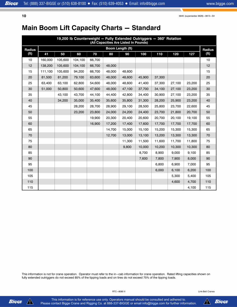
Main Boom Lift Capacity Charts - Standard
19,200 lb Counterweight - Fully Extended Outriggers - 360° Rotation(All Capacities Are Listed In Pounds)
Radius(ft)
Boom Length (ft) Radius(ft)41 50 60 70 80 90 100 110 120 127
10 160,000 105,600 104,100 66,700 10
12 138,200 105,600 104,100 66,700 48,000 12
15 111,100 105,600 94,200 66,700 48,000 48,600 15
20 81,500 81,200 79,100 63,600 48,000 48,600 45,900 37,300 20
25 63,400 63,100 62,800 54,600 48,000 48,600 41,400 37,300 27,100 23,200 25
30 51,000 50,800 50,600 47,600 48,000 47,100 37,700 34,100 27,100 23,200 30
35 43,100 43,700 44,100 44,400 42,800 34,400 30,900 27,100 23,200 35
40 34,200 35,000 35,400 35,600 35,800 31,300 28,200 25,900 23,200 40
45 28,200 28,700 28,900 29,100 28,500 25,800 23,700 22,600 45
50 23,200 23,800 24,000 24,200 24,400 23,700 21,800 20,700 50
55 19,900 20,300 20,400 20,600 20,700 20,100 19,100 55
60 16,900 17,200 17,400 17,600 17,700 17,700 17,700 60
65 14,700 15,000 15,100 15,200 15,300 15,300 65
70 12,700 13,000 13,100 13,200 13,300 13,300 70
75 11,300 11,500 11,600 11,700 11,800 75
80 9,800 10,000 10,200 10,300 10,300 80
85 8,700 8,900 9,000 9,100 85
90 7,600 7,800 7,900 8,000 90
95 6,800 6,900 7,000 95
100 6,000 6,100 6,200 100
105 5,300 5,400 105
110 4,600 4,700 110
115 4,100 115
This information is not for crane operation. Operator must refer to the in-cab information for crane operation. Rated lifting capacities shown onfully extended outriggers do not exceed 85% of the tipping loads and on tires do not exceed 75% of the tipping loads.

115640 (supersedes 5628)-0613-S4
RTC-8080 IILink‐Belt Cranes
Fly Attachment Lift Capacity Charts - Optional19,200 lb Counterweight - Fully Extended Outriggers - 360° Rotation
(All Capacities Are Listed In Pounds)
Main Boom + 10 ft Manual Offset Fly (2°, 15°, 30° & 45° Offsets)
Radius(ft)
Boom Length (ft) Radius(ft)41 50 60 70 80 90 100 110 120 127
10 40,300 41,000 41,200 10
12 35,000 35,400 35,500 39,800 39,300 12
15 34,200 34,600 34,800 34,700 34,300 38,000 15
20 33,200 33,600 33,900 33,800 33,600 33,300 35,700 20
25 32,600 32,900 33,200 33,200 33,000 32,800 32,000 29,300 23,900 25
30 32,500 32,500 32,700 32,700 32,500 31,700 29,700 27,500 23,900 20,300 30
35 32,500 32,500 32,400 32,300 31,500 29,700 27,700 25,800 23,900 20,300 35
40 32,500 32,500 32,400 31,700 29,800 27,900 26,000 24,200 22,500 20,300 40
45 29,200 29,200 29,200 28,200 26,300 24,400 22,600 21,200 20,200 45
50 24,300 24,300 24,300 24,400 24,400 22,700 21,100 19,700 18,900 50
55 20,500 20,600 20,600 20,600 20,600 19,700 18,400 17,700 55
60 17,600 17,600 17,600 17,600 17,600 17,500 17,100 16,300 60
65 15,100 15,100 15,100 15,100 15,100 15,100 15,000 65
70 13,200 13,100 13,100 13,100 13,100 13,100 13,100 70
75 11,500 11,500 11,500 11,500 11,500 11,500 75
80 10,100 10,100 10,100 10,100 10,100 10,100 80
85 8,800 8,800 8,800 8,800 8,800 85
90 7,800 7,800 7,800 7,700 7,700 90
95 6,800 6,800 6,800 6,800 95
100 6,000 6,000 6,000 6,000 100
105 5,200 5,200 5,200 105
110 4,600 4,500 4,500 110
115 3,900 3,900 115
120 3,400 3,400 120
125 2,900 125
130 2,500 130
This information is not for crane operation. Operator must refer to the in-cab information for crane operation. Rated lifting capacities shown onfully extended outriggers do not exceed 85% of the tipping loads and on tires do not exceed 75% of the tipping loads.
12 5640 (supersedes 5628)-0613-S4
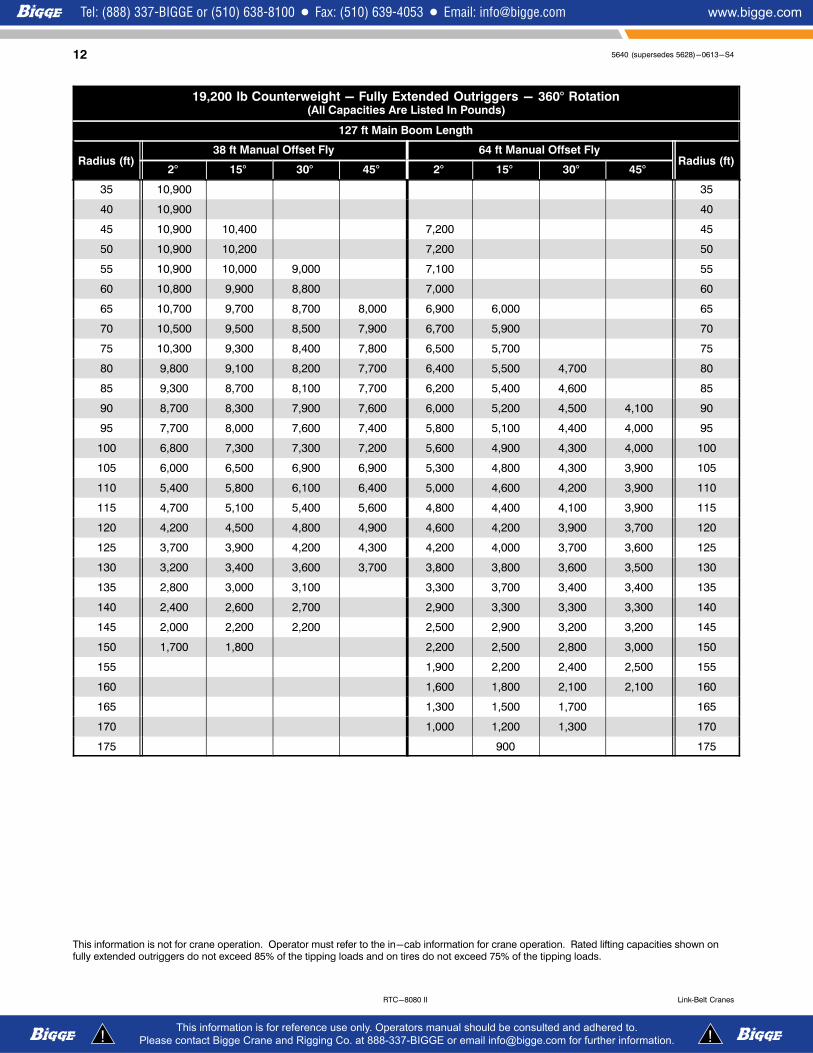
RTC-8080 II Link‐Belt Cranes
19,200 lb Counterweight - Fully Extended Outriggers - 360° Rotation(All Capacities Are Listed In Pounds)
127 ft Main Boom Length
Radius (ft)38 ft Manual Offset Fly 64 ft Manual Offset Fly
Radius (ft)2° 15° 30° 45° 2° 15° 30° 45°
35 10,900 35
40 10,900 40
45 10,900 10,400 7,200 45
50 10,900 10,200 7,200 50
55 10,900 10,000 9,000 7,100 55
60 10,800 9,900 8,800 7,000 60
65 10,700 9,700 8,700 8,000 6,900 6,000 65
70 10,500 9,500 8,500 7,900 6,700 5,900 70
75 10,300 9,300 8,400 7,800 6,500 5,700 75
80 9,800 9,100 8,200 7,700 6,400 5,500 4,700 80
85 9,300 8,700 8,100 7,700 6,200 5,400 4,600 85
90 8,700 8,300 7,900 7,600 6,000 5,200 4,500 4,100 90
95 7,700 8,000 7,600 7,400 5,800 5,100 4,400 4,000 95
100 6,800 7,300 7,300 7,200 5,600 4,900 4,300 4,000 100
105 6,000 6,500 6,900 6,900 5,300 4,800 4,300 3,900 105
110 5,400 5,800 6,100 6,400 5,000 4,600 4,200 3,900 110
115 4,700 5,100 5,400 5,600 4,800 4,400 4,100 3,900 115
120 4,200 4,500 4,800 4,900 4,600 4,200 3,900 3,700 120
125 3,700 3,900 4,200 4,300 4,200 4,000 3,700 3,600 125
130 3,200 3,400 3,600 3,700 3,800 3,800 3,600 3,500 130
135 2,800 3,000 3,100 3,300 3,700 3,400 3,400 135
140 2,400 2,600 2,700 2,900 3,300 3,300 3,300 140
145 2,000 2,200 2,200 2,500 2,900 3,200 3,200 145
150 1,700 1,800 2,200 2,500 2,800 3,000 150
155 1,900 2,200 2,400 2,500 155
160 1,600 1,800 2,100 2,100 160
165 1,300 1,500 1,700 165
170 1,000 1,200 1,300 170
175 900 175
This information is not for crane operation. Operator must refer to the in-cab information for crane operation. Rated lifting capacities shown onfully extended outriggers do not exceed 85% of the tipping loads and on tires do not exceed 75% of the tipping loads.
135640 (supersedes 5628)-0613-S4
RTC-8080 IILink‐Belt Cranes
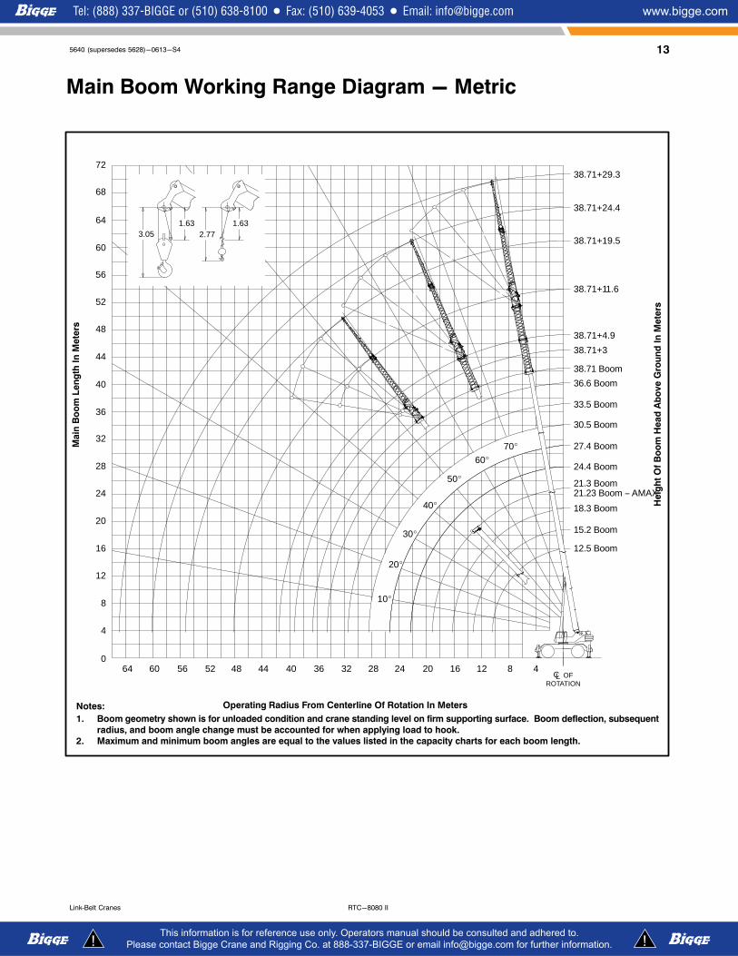
Main Boom Working Range Diagram - Metric
70�
60�
50�
40�
30�
20�
10�
Notes:
1. Boom geometry shown is for unloaded condition and crane standing level on firm supporting surface. Boom deflection, subsequent
radius, and boom angle change must be accounted for when applying load to hook.
2. Maximum and minimum boom angles are equal to the values listed in the capacity charts for each boom length.
ÁÁÁÁÁÁÁÁÁÁÁÁÁÁÁÁÁÁÁÁÁÁÁÁÁÁÁÁÁÁÁÁÁÁÁÁÁÁÁÁÁÁÁÁÁÁÁÁÁÁÁÁÁÁÁÁÁÁÁÁÁÁÁ
Main
Bo
om
Len
gth
In
Mete
rs
Heig
ht
Of
Bo
om
Head
Ab
ove G
rou
nd
In
Mete
rs
Operating Radius From Centerline Of Rotation In Meters
12.5 Boom
15.2 Boom
0
4
8
12
16
20
24
28
32
36
40
44
48
52
56
60
38.71+29.3
38.71+24.4
38.71+19.5
38.71+11.6
38.71+4.9
38.71+3
38.71 Boom
36.6 Boom
33.5 Boom
30.5 Boom
27.4 Boom
24.4 Boom
21.3 Boom
283236CL
ROTATION
404448525660 24 20 16
18.3 Boom
21.23 Boom − AMAX
OF12 8 4
64
68
72
64
ÁÁÁÁÁÁÁÁÁÁÁÁÁÁÁÁÁÁÁÁÁÁÁÁÁÁÁÁÁÁÁÁÁÁÁÁÁÁÁÁÁÁÁÁÁÁÁÁÁÁÁÁÁÁÁÁÁÁÁÁÁÁÁ
3.051.63
2.771.63
14 5640 (supersedes 5628)-0613-S4
RTC-8080 II Link‐Belt Cranes
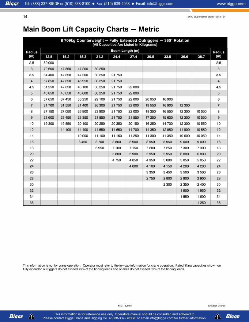
Main Boom Lift Capacity Charts - Metric
8 709kg Counterweight - Fully Extended Outriggers - 360° Rotation(All Capacities Are Listed In Kilograms)
Radius(m)
Boom Length (m) Radius(m)12.5 15.2 18.3 21.2 24.4 27.4 30.5 33.5 36.6 38.7
2.5 80 000 2.5
3 72 600 47 850 47 200 30 250 3
3.5 64 400 47 850 47 200 30 250 21 750 3.5
4 57 850 47 850 45 950 30 250 21 750 4
4.5 51 250 47 850 43 100 30 250 21 750 22 000 4.5
5 45 850 45 650 40 600 30 250 21 750 22 000 5
6 37 650 37 450 36 250 29 100 21 750 22 000 20 950 16 900 6
7 31 700 31 550 31 400 26 300 21 750 22 000 19 550 16 900 12 300 7
8 27 150 27 050 26 900 23 900 21 750 22 000 18 350 16 550 12 300 10 550 8
9 23 600 23 450 23 350 21 850 21 750 21 550 17 250 15 600 12 300 10 550 9
10 19 300 19 850 20 100 20 250 20 350 20 150 16 250 14 700 12 300 10 550 10
12 14 100 14 400 14 550 14 650 14 700 14 350 12 950 11 900 10 550 12
14 10 900 11 100 11 150 11 250 11 300 11 350 10 600 10 050 14
16 8 450 8 700 8 800 8 900 8 950 8 950 9 000 9 000 16
18 6 950 7 100 7 150 7 200 7 250 7 300 7 300 18
20 5 800 5 900 5 950 5 950 6 000 6 000 20
22 4 750 4 850 4 950 5 000 5 050 5 050 22
24 4 000 4 100 4 150 4 200 4 200 24
26 3 350 3 450 3 500 3 500 26
28 2 750 2 800 2 900 2 900 28
30 2 300 2 350 2 400 30
32 1 900 1 950 32
34 1 550 1 600 34
36 1 250 36
This information is not for crane operation. Operator must refer to the in-cab information for crane operation. Rated lifting capacities shown onfully extended outriggers do not exceed 75% of the tipping loads and on tires do not exceed 65% of the tipping loads.
155640 (supersedes 5628)-0613-S4
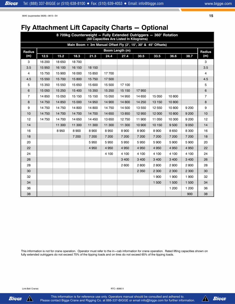
RTC-8080 IILink‐Belt Cranes
Fly Attachment Lift Capacity Charts - Optional8 709kg Counterweight - Fully Extended Outriggers - 360° Rotation
(All Capacities Are Listed In Kilograms)
Main Boom + 3m Manual Offset Fly (2°, 15°, 30° & 45° Offsets)
Radius(m)
Boom Length (m) Radius(m)12.5 15.2 18.3 21.3 24.4 27.4 30.5 33.5 36.6 38.7
3 16 200 18 650 18 700 3
3.5 15 950 16 100 16 150 18 150 3.5
4 15 750 15 900 16 000 15 850 17 700 4
4.5 15 550 15 700 15 800 15 750 17 500 4.5
5 15 350 15 550 15 650 15 600 15 500 17 100 5
6 15 050 15 250 15 400 15 350 15 250 15 150 17 950 6
7 14 850 15 050 15 150 15 150 15 050 14 950 14 650 15 050 10 800 7
8 14 750 14 850 15 000 14 950 14 900 14 800 14 250 13 150 10 800 8
9 14 750 14 750 14 800 14 800 14 750 14 500 13 550 12 550 10 800 9 200 9
10 14 750 14 700 14 700 14 700 14 650 13 850 12 950 12 000 10 800 9 200 10
12 14 750 14 700 14 650 14 450 13 650 12 750 11 900 11 050 10 300 9 200 12
14 11 300 11 300 11 300 11 300 11 300 10 900 10 150 9 500 9 050 14
16 8 950 8 900 8 900 8 950 8 900 8 900 8 900 8 650 8 300 16
18 7 200 7 200 7 200 7 200 7 200 7 200 7 200 7 200 18
20 5 950 5 950 5 950 5 950 5 900 5 900 5 900 20
22 4 950 4 950 4 950 4 950 4 950 4 950 4 950 22
24 4 100 4 100 4 100 4 100 4 100 4 100 24
26 3 400 3 400 3 400 3 400 3 400 26
28 2 600 2 800 2 800 2 800 2 800 28
30 2 350 2 300 2 300 2 300 30
32 1 900 1 900 1 900 32
34 1 500 1 500 1 500 34
36 1 200 1 200 36
38 900 38
This information is not for crane operation. Operator must refer to the in-cab information for crane operation. Rated lifting capacities shown onfully extended outriggers do not exceed 75% of the tipping loads and on tires do not exceed 65% of the tipping loads.
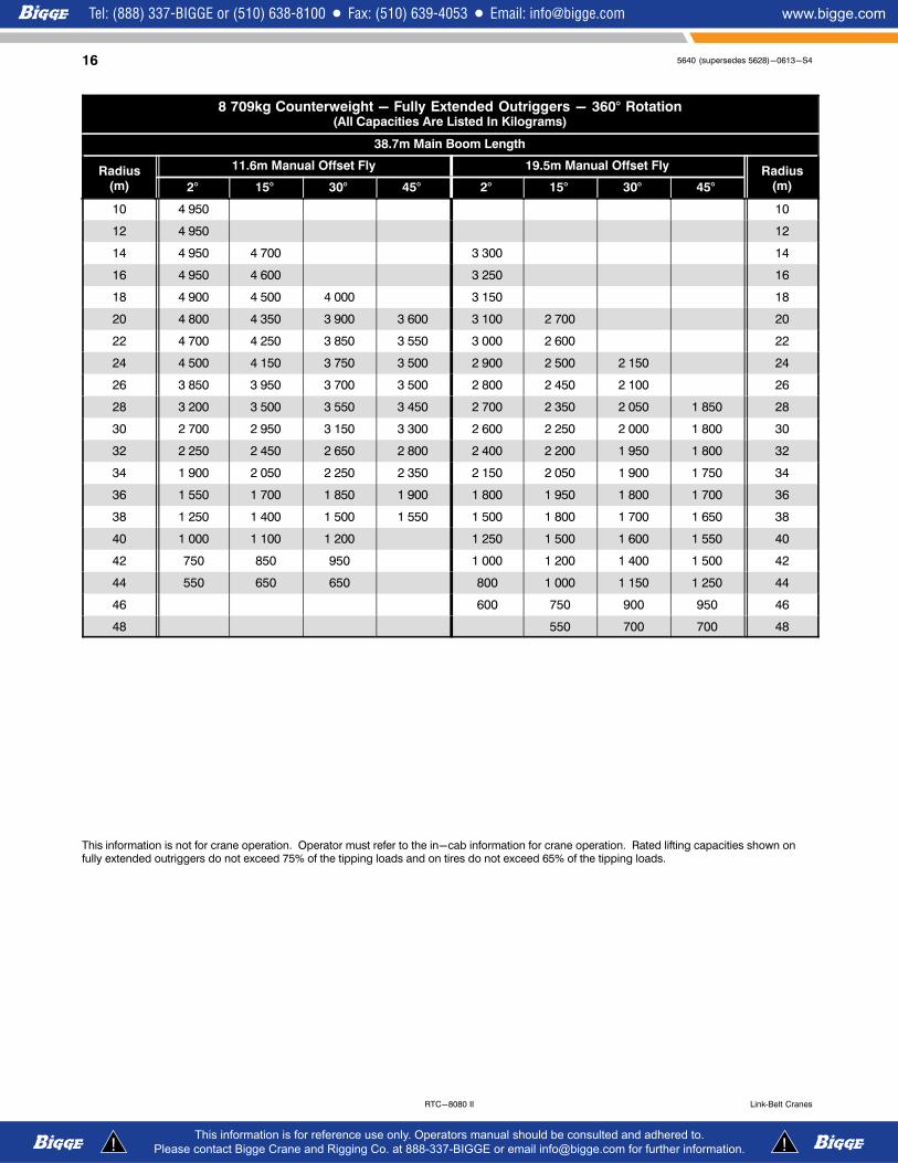
16 5640 (supersedes 5628)-0613-S4
RTC-8080 II Link‐Belt Cranes
8 709kg Counterweight - Fully Extended Outriggers - 360° Rotation(All Capacities Are Listed In Kilograms)
38.7m Main Boom Length
Radius(m)
11.6m Manual Offset Fly 19.5m Manual Offset Fly Radius(m)2° 15° 30° 45° 2° 15° 30° 45°
10 4 950 10
12 4 950 12
14 4 950 4 700 3 300 14
16 4 950 4 600 3 250 16
18 4 900 4 500 4 000 3 150 18
20 4 800 4 350 3 900 3 600 3 100 2 700 20
22 4 700 4 250 3 850 3 550 3 000 2 600 22
24 4 500 4 150 3 750 3 500 2 900 2 500 2 150 24
26 3 850 3 950 3 700 3 500 2 800 2 450 2 100 26
28 3 200 3 500 3 550 3 450 2 700 2 350 2 050 1 850 28
30 2 700 2 950 3 150 3 300 2 600 2 250 2 000 1 800 30
32 2 250 2 450 2 650 2 800 2 400 2 200 1 950 1 800 32
34 1 900 2 050 2 250 2 350 2 150 2 050 1 900 1 750 34
36 1 550 1 700 1 850 1 900 1 800 1 950 1 800 1 700 36
38 1 250 1 400 1 500 1 550 1 500 1 800 1 700 1 650 38
40 1 000 1 100 1 200 1 250 1 500 1 600 1 550 40
42 750 850 950 1 000 1 200 1 400 1 500 42
44 550 650 650 800 1 000 1 150 1 250 44
46 600 750 900 950 46
48 550 700 700 48
This information is not for crane operation. Operator must refer to the in-cab information for crane operation. Rated lifting capacities shown onfully extended outriggers do not exceed 75% of the tipping loads and on tires do not exceed 65% of the tipping loads.

175640 (supersedes 5628)-0613-S4
RTC-8080 IILink‐Belt Cranes
This Page Intentionally Blank

18 5640 (supersedes 5628)-0613-S4
RTC-8080 II Link‐Belt Cranes
This Page Intentionally Blank

195640 (supersedes 5628)-0613-S4
RTC-8080 IILink‐Belt Cranes
This Page Intentionally Blank

5640 (supersedes 5628)-0613-S4
RTC-8080 II Link‐Belt Cranes
Link−Belt Construction Equipment Company Lexington, Kentucky www.linkbelt.com�Link−Belt is a registered trademark. Copyright 2013. We are constantly improving our products and therefore reserve the right to change designs and specifications.