Embed Size (px)
Citation preview

OWNERS MANUALMODEL #575
KRENDL MACHINE COMPANY • 1201 SPENCERVILLE RDDELPHOS, OHIO 45833 • TELEPHONE 800-459-2069 • FAX 419-695-9301
E - MAIL: [email protected] • WEB SITE: www.krendlmachine.com
60 YEARS OF AMERICAN INGENUITY

CONGRATULATIONS ON YOUR PURCHASE OF KRENDL EQUIPMENT
MODEL #575OWNER'S MANUAL
FOR ASSURED SAFETY AND CONFIDENCE, PLEASE READ THISMANUAL CAREFULLY BEFORE INSTALLING AND OPERATINGYOUR MACHINE.
E-MAIL ADDRESS IS: [email protected] SITE IS: www.krendlmachine.com
INTRODUCTION . . . . . . . . . . . . . . . . . . . . . . . . . . . . . . . .
GENERAL SAFETY INFORMATION . . . . . . . . . . . . . . . . . .
DECALS . . . . . . . . . . . . . . . . . . . . . . . . . . . . . . . . . . . . . .
WARRANTY . . . . . . . . . . . . . . . . . . . . . . . . . . . . . . . . . . . .
RETURNED GOODS PROCEDURE and SPECIFICATIONS
BASIC COMPONENTS . . . . . . . . . . . . . . . . . . . . . . . . . . .
OPERATING INSTRUCTIONSMachine Hookup . . . . . . . . . . . . . . . . . . . . . . . . . . . . .Electrical Operation . . . . . . . . . . . . . . . . . . . . . . . . . . .Mechanical Settings . . . . . . . . . . . . . . . . . . . . . . . . . .
GENERAL MAINTENANCE . . . . . . . . . . . . . . . . . . . . . . . . .
TROUBLESHOOTING . . . . . . . . . . . . . . . . . . . . . . . . . . . .
SPARE PARTS LIST . . . . . . . . . . . . . . . . . . . . . . . . . . . . . .
ELECTRICAL . . . . . . . . . . . . . . . . . . . . . . . . . . . . . . . . . . .
LADDER DIAGRAM . . . . . . . . . . . . . . . . . . . . . . . . . . . . . .
PARTS LIST . . . . . . . . . . . . . . . . . . . . . . . . . . . . . . . . . . . .
INSTALLATION INSTRUCTIONS . . . . . . . . . . . . . . . . . . . .
GLOSSARY . . . . . . . . . . . . . . . . . . . . . . . . . . . . . . . . . . . .
SERVICE RECORD. . . . . . . . . . . . . . . . . . . . . . . . . . . . . .
PAGE
1
2-3
4-5
6
7
8
9-1112-1313-14
15-18
18-19
19
20-23
24-27
28-34
35
36
37
Table of Contents
Rev. Date: 4/14/21 Page 1
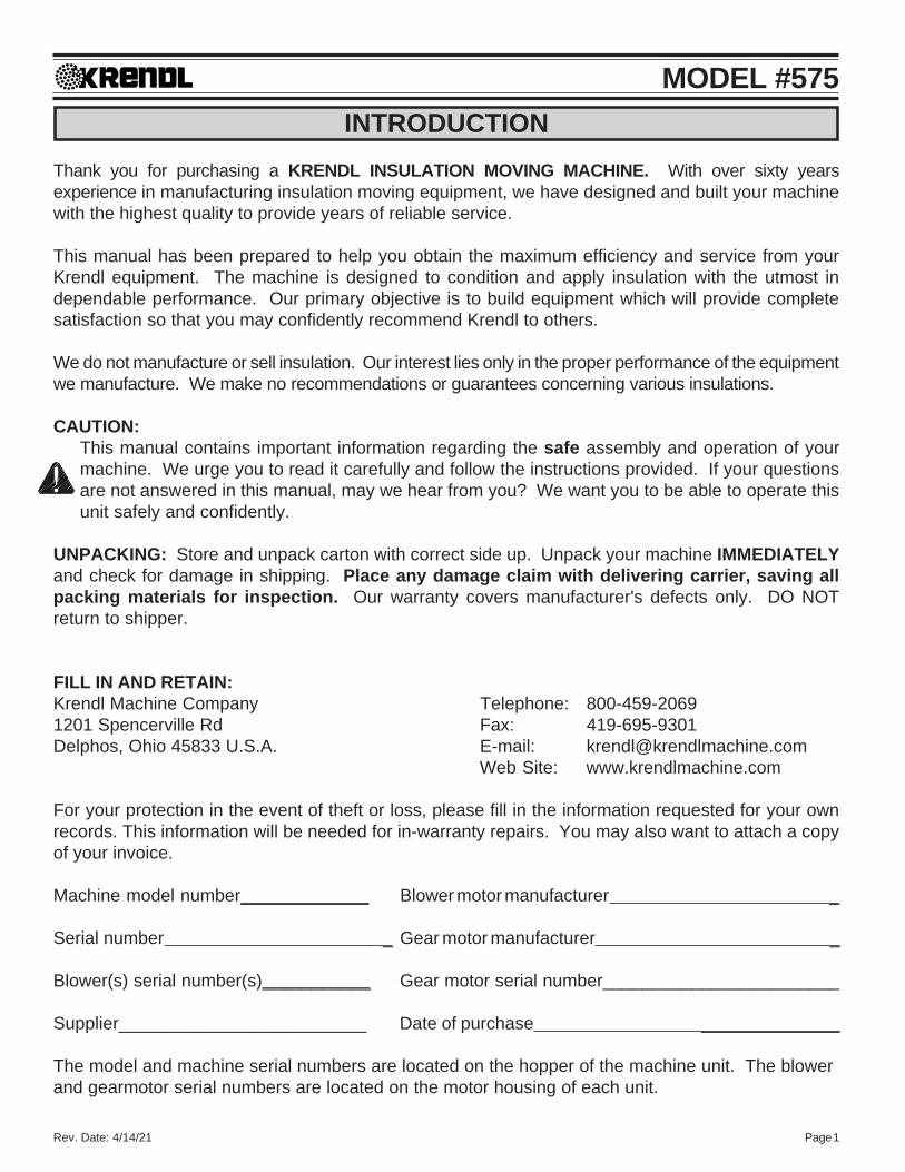
MODEL #575INTRODUCTION
Thank you for purchasing a KRENDL INSULATION MOVING MACHINE. With over sixty yearsexperience in manufacturing insulation moving equipment, we have designed and built your machinewith the highest quality to provide years of reliable service.
This manual has been prepared to help you obtain the maximum efficiency and service from yourKrendl equipment. The machine is designed to condition and apply insulation with the utmost independable performance. Our primary objective is to build equipment which will provide completesatisfaction so that you may confidently recommend Krendl to others.
We do not manufacture or sell insulation. Our interest lies only in the proper performance of the equipmentwe manufacture. We make no recommendations or guarantees concerning various insulations.
CAUTION:This manual contains important information regarding the safe assembly and operation of yourmachine. We urge you to read it carefully and follow the instructions provided. If your questionsare not answered in this manual, may we hear from you? We want you to be able to operate thisunit safely and confidently.
UNPACKING: Store and unpack carton with correct side up. Unpack your machine IMMEDIATELYand check for damage in shipping. Place any damage claim with delivering carrier, saving allpacking materials for inspection. Our warranty covers manufacturer's defects only. DO NOTreturn to shipper.
FILL IN AND RETAIN:Krendl Machine Company Telephone: 800-459-20691201 Spencerville Rd Fax: 419-695-9301Delphos, Ohio 45833 U.S.A. E-mail: [email protected]
Web Site: www.krendlmachine.com
For your protection in the event of theft or loss, please fill in the information requested for your ownrecords. This information will be needed for in-warranty repairs. You may also want to attach a copyof your invoice.
Machine model number_____________ Blower motor manufacturer _
Serial number _ Gear motor manufacturer _
Blower(s) serial number(s)___________ Gear motor serial number________________________
Supplier_________________________ Date of purchase ______________
The model and machine serial numbers are located on the hopper of the machine unit. The blowerand gearmotor serial numbers are located on the motor housing of each unit.
Rev. Date: 4/14/21 Page 2
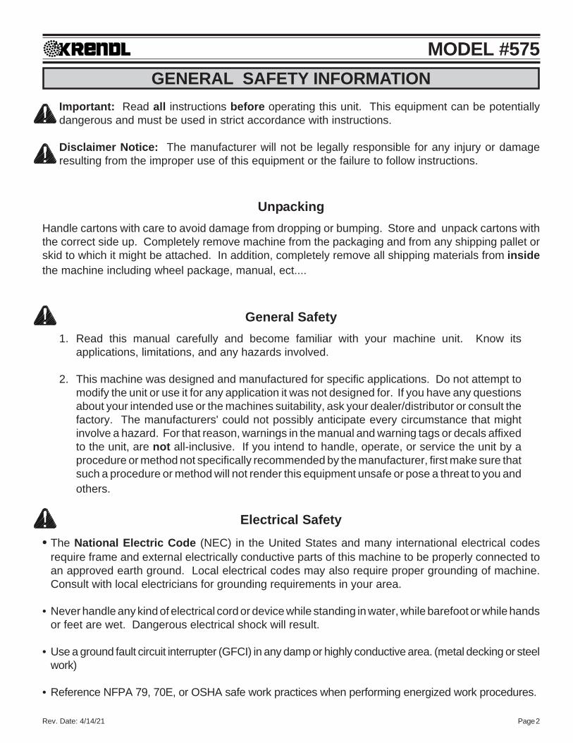
MODEL #575GENERAL SAFETY INFORMATION
Important: Read all instructions before operating this unit. This equipment can be potentiallydangerous and must be used in strict accordance with instructions.
Disclaimer Notice: The manufacturer will not be legally responsible for any injury or damageresulting from the improper use of this equipment or the failure to follow instructions.
UnpackingHandle cartons with care to avoid damage from dropping or bumping. Store and unpack cartons withthe correct side up. Completely remove machine from the packaging and from any shipping pallet orskid to which it might be attached. In addition, completely remove all shipping materials from insidethe machine including wheel package, manual, ect....
General Safety1. Read this manual carefully and become familiar with your machine unit. Know its
applications, limitations, and any hazards involved.
2. This machine was designed and manufactured for specific applications. Do not attempt tomodify the unit or use it for any application it was not designed for. If you have any questionsabout your intended use or the machines suitability, ask your dealer/distributor or consult thefactory. The manufacturers' could not possibly anticipate every circumstance that mightinvolve a hazard. For that reason, warnings in the manual and warning tags or decals affixedto the unit, are not all-inclusive. If you intend to handle, operate, or service the unit by aprocedure or method not specifically recommended by the manufacturer, first make sure thatsuch a procedure or method will not render this equipment unsafe or pose a threat to you andothers.
Electrical Safety• The National Electric Code (NEC) in the United States and many international electrical codes
require frame and external electrically conductive parts of this machine to be properly connected toan approved earth ground. Local electrical codes may also require proper grounding of machine.Consult with local electricians for grounding requirements in your area.
• Never handle any kind of electrical cord or device while standing in water, while barefoot or while handsor feet are wet. Dangerous electrical shock will result.
• Use a ground fault circuit interrupter (GFCI) in any damp or highly conductive area. (metal decking or steelwork)
• Reference NFPA 79, 70E, or OSHA safe work practices when performing energized work procedures.

Rev. Date: 4/14/21 Page 3
MODEL #575Safety/Caution
• Be Safe - Keep away from moving parts.• Be Safe - Make sure all guards and hopper bar are in proper place before operating machine. Guards
and safety devices/switches should not be removed, modified or by-passed. Hands shouldnever pass below hopper bar.
• Be Safe - Do not remove motors or lift hopper when unit is connected to power supply.• Be Safe - Make sure machine is properly grounded. Protect all electrical supply cords from sharp
objects, moisture, and other potentially hazardous materials. Keep power cords in goodrepair. Electrical service must be performed by a qualified electrician.
• Be Safe - Disconnect power supply before inspecting or adjusting unit.• Be Safe - Consult a qualified technician to answer questions before attempting to operate, or injury
may result.• Be Safe - Do not operate machine alone.• Be Safe - Do not leave machine unattended and energized.• Be Safe - Turn machine off and disconnect electricity before clearing and feeding jam or attempting
to remove any object dropped in the hopper.• Be Safe - Keep hands, loose clothing, jewelry and hair away from agitators, gears, chains and other
moving parts.• Be Safe - Use proper lifting when moving insulation and loading machine.• Be Safe - Keep work area clear of debris.• Be Safe - Wear proper safety equipment, including protective gear, such as respirators, eye and ear
protection.• Be Safe - Violation of the Owner's Manual or safety precautions may void warranty.
Make Sure!• Hopper is empty of foreign objects before starting.• Adequate electrical power is supplied or damage to unit will result.• Blower filter is kept clean and in place when blower is on.• Machine is turned off immediately if hose is plugged, or blower will overheat.• Machine must be on before adding insulation.• Blower(s) must be on, when agitators are running, or machine will bind.• Agitator motor is not run with hopper empty for more than a few minutes, or damage to seals will result.• Sprockets, chains, belts and pulleys are correctly aligned and tensioned.• Pieces of bag are not left in the machine as this can bind and stall your machine.• This machine should only be used with good quality insulations that are dry, undamaged and that meet
a certain industry specification or quality standards.• Set screws on tension bar inside hopper have not backed out due to vibration. This could cause
material to get underneath the base and damage motors. Failure to check will void the warranty onmotors.
Rev. Date: 4/14/21 Page 4
MODEL #575DECALS
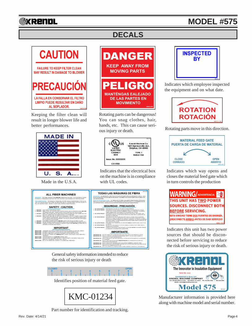
Indicates that the electrical boxon the machine is in compliancewith UL codes.Made in the U.S.A.
Identifies position of material feed gate.
Indicates this unit has two powersources that should be discon-nected before servicing to reducethe risk of serious injury or death.
Rotating parts can be dangerous!You can snag clothes, hair,hands, etc. This can cause seri-ous injury or death. Rotating parts move in this direction.
Keeping the filter clean willresult in longer blower life andbetter performances.
Manufacturer information is provided herealong with machine model and serial number.
Indicates which way opens andcloses the material feed gate whichin turn controls the production
General safety information intended to reducethe risk of serious injury or death
KMC-01234Part number for identification and tracking.
Indicates which employee inspectedthe equipment and on what date.
Rev. Date: 4/14/21 Page 5
MODEL #575
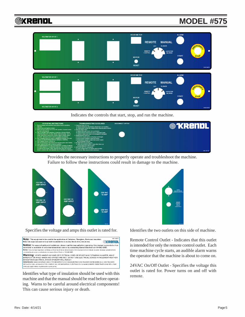
Indicates the controls that start, stop, and run the machine.
Provides the necessary instructions to properly operate and troubleshoot the machine.Failure to follow these instructions could result in damage to the machine.
Specifies the voltage and amps this outlet is rated for. Identifies the two outlets on this side of machine.
Remote Control Outlet - Indicates that this outletis intended for only the remote control outlet. Eachtime machine cycle starts, an audible alarm warnsthe operator that the machine is about to come on.
24VAC On/Off Outlet - Specifies the voltage thisoutlet is rated for. Power turns on and off withremote.Identifies what type of insulation should be used with this
machine and that the manual should be read before operat-ing. Warns to be careful around electrical components!This can cause serious injury or death.

Rev. Date: 4/14/21 Page 6
MODEL #575WARRANTY:
Krendl Machine Company (Company) warrants to each original purchaser (Buyer) of itsmachines that such products will be free of manufacturing defects for a period of 2 years fromthe date of shipment to the Buyer. (This does not include accessories, pumps, blowers, wallscrubbers, etc.)
No warranty is made with respect to:
1. Components or accessories manufactured and warranted by others. Warranties forpurchased component parts as supplied from vendor such as engine, electric motor,blower, gearbox, transmission, etc., if furnished by the manufacturer of the component,are on file at the Company’s main office and copies will be furnished at request of Buyer.Component(s), shipping costs prepaid, shall be sent to Company who in turn shall forwardto vendor for evaluation and warranty determination.
2. Any defect caused by repair, alteration and/or adjustment performed by Buyer or customer/vendor of Buyer without the express written authorization of the Company.
3. The labor costs of replacing parts by parties other than the Company.4. Any machine that has not been operated and/or maintained in accordance with normal
industry practice and the written recommendations of the Company. (e.g. machine oper-ated with an improperly sized, worn or damaged hose, improper or inattention to preven-tative maintenance, etc.)
5. The product has been subjected to misuse, negligence or accident or results of anyapplication or use of the blowing equipment not in accordance with the Company recom-mendations.
This limited warranty does not cover the free replacement of component parts that becomeinoperative due to wear and usage and need to be replaced on a regular basis, including but notlimited to: airlock seal(s), agitator(s), shredder(s), auger(s), fuse(s), switch(es), clutch(es),hose(s), shaft seal(s), chain(s), belt(s), sprocket(s), pulley(s), bearing(s), cable(s), battery(ies),filter(s), fan(s), etc.
The Company’s obligation under this warranty is limited to repairing or replacing (at Companyoption) any part that is determined by the Company to be suffering from a manufacturing defect.The Company (at Company option) will provide any required parts and labor to the Buyer. If theequipment or parts must be returned to the Company for repair, all transportation costs shall bethe Buyer’s responsibility.
THIS LIMITED WARRANTY IS EXPRESSLY IN LIEU OF ANY OTHER GUARANTEES AND / ORWARRANTIES, ORAL OR WRITTEN, EXPRESSED OR IMPLIED, INCLUDING WITHOUT LIMITA-TION, THE IMPLIED WARRANTY OF MERCHANTABILITY. NO WARRANTY, EXPRESS ORIMPLIED, OTHER THAN THE AFORESAID WARRANTY IS MADE OR AUTHORIZED BY COM-PANY. COMPANY SHALL NOT BE LIABLE FOR ANY DIRECT, INDIRECT, INCIDENTAL ORCONSEQUENTIAL DAMAGES TO PROPERTY OR INJURY TO ANY PERSON OR COSTS ASSO-CIATED WITH LOSS OF PRODUCTION RESULTING IN LOSS OF REVENUE, PROFITS OR LOSSOF EQUIPMENT THROUGH THE USE OF THIS EQUIPMENT.
Note: Special job circumstances incurring costs for specialized repair and next day deliveryof parts will not be reimbursed by the manufacturer unless authorized by factory.

Rev. Date: 4/14/21 Page 7
MODEL #575RETURNED GOODS PROCEDURE:
IF MACHINE WAS NOT PURCHASED DIRECTLY FROM KRENDL MACHINE COMPANY, CON-TACT YOUR SUPPLIER / DISTRIBUTOR.
When returning products to Krendl for repair, first obtain a return goods authorization, at which timeyou will be given shipping instructions. The product must be shipped PREPAID:
Krendl Machine Company Telephone: 800-459-20691201 Spencerville Rd Fax: 419-695-9301Delphos, Ohio 45833 U.S.A. E-mail: [email protected]
Web Site: www.krendlmachine.com
Once the unit is received, it will be inspected. In-warranty units will be repaired and returnedimmediately. An estimate of repair charges will be provided for out-of-warranty units.
SPECIFICATIONSU.S.
MODEL#: 575
HEIGHT: 63" (160 cm)WIDTH (DEPTH): 28" (71 cm)LENGTH: 38" (97 cm)WEIGHT: 382 pounds (173 kg)ELECTRICAL: 120VAC, (1) 15 amp, (1) 30 amp, D.I.
240VAC, (1) 30 amp, S.I.230VAC, (2) 16 amp, D.I.
BLOWER VOLUME: (2) 140 CFMBLOWER PRESSURE: 4 1/2 PSI maximumHOSE OUTPUT: 3” diameter (7.6 cm)
MAXIMUM FEED RATES:CELLULOSE: 2600-2800 lbs/hr (1179-1270 kg/hr) 87-93 bags per hourFIBERGLASS: 800-1000 lbs/hr (363-454 kg/hr) 27-33 bags per hour
WARNING: Recommended hose size, type and length must be used to achieve maximum results. Krendlcannot guarantee performance of the machine if hoses are undersized, worn, damaged, orhoses other than those we recommend are used.
BEFORE YOU RUN THIS MACHINE...PLEASE READ THE REST OF THIS MANUAL!!

Rev. Date: 4/14/21 Page 8
MODEL #575
G
BASIC COMPONENTS: #575This is a view of the basic components of your #575 machine. It shows the location of each item andgives the function of each. Use this as a guide throughout the manual.
A) BASE UNIT — Lower frame unit supportingblower, gearmotor, airlock and hopper.
B) AIRLOCK — Traps air and insulation whileproviding a metered flow.
C) MOTOR & REDUCER — Provides drivingpower of agitation system. Increases outputpower while decreasing speed of the agita-tors and airlock.
D) BLOWER (2)— Creates air pressure to blowinsulation out of airlock.
E) AGITATORS (2) — Conditions insulation inthe hopper.
F) HOPPER — Upper unit of machine holdinginsulation.
G) MAIN CONTROL PANEL — Connects withmain power, allowing operation of unit atmachine.
H) EMERGENCY STOP BUTTON — Safetydevice for immediate stopping of machine.(Located on electrical box)
I) SLIDEGATE — Meters the amount of insu-lation dropping into airlock by controllingsize of airlock opening
F
A
B
C
E
D
EI
H
Rev. Date: 4/14/21 Page 9
MODEL #575
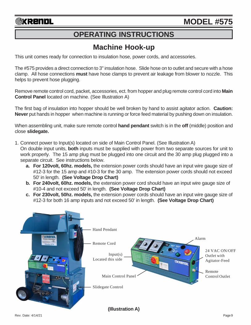
Hand Pendant
Remote Cord
Slidegate Control
24 VAC ON/OFFOutlet withAgitator-Feed
RemoteControl Outlet
Alarm
Input(s)Located this side
Main Control Panel
OPERATING INSTRUCTIONSMachine Hook-up
This unit comes ready for connection to insulation hose, power cords, and accessories.
The #575 provides a direct connection to 3" insulation hose. Slide hose on to outlet and secure with a hoseclamp. All hose connections must have hose clamps to prevent air leakage from blower to nozzle. Thishelps to prevent hose plugging.
Remove remote control cord, packet, accessories, ect. from hopper and plug remote control cord into MainControl Panel located on machine. (See Illustration A)
The first bag of insulation into hopper should be well broken by hand to assist agitator action. Caution:Never put hands in hopper when machine is running or force feed material by pushing down on insulation.
When assembling unit, make sure remote control hand pendant switch is in the off (middle) position andclose slidegate.
1. Connect power to Input(s) located on side of Main Control Panel. (See Illustration A)On double input units, both inputs must be supplied with power from two separate sources for unit towork properly. The 15 amp plug must be plugged into one circuit and the 30 amp plug plugged into aseparate circuit. See instructions below.
a. For 120volt, 60hz. models, the extension power cords should have an input wire gauge size of#12-3 for the 15 amp and #10-3 for the 30 amp. The extension power cords should not exceed50' in length. (See Voltage Drop Chart)
b. For 240volt, 60hz. models, the extension power cord should have an input wire gauge size of#10-4 and not exceed 50' in length. (See Voltage Drop Chart)
c. For 230volt, 50hz. models, the extension power cords should have an input wire gauge size of#12-3 for both 16 amp inputs and not exceed 50' in length. (See Voltage Drop Chart)
(Illustration A)

Rev. Date: 4/14/21 Page 10
MODEL #575
Ex: A two-wire 20-ampere circuit using 12 AWG with a one-way distance of 25 feet will drop 1.98 volts;120 volts - 1.98 volts = 118.02 volts as the load voltage.240 volts - 1.98 volts = 238.02 volts as the load voltage.230 volts - 1.98 volts = 228.02 volts as the load voltage.
Caution: Operating unit with less than required voltage, more than required voltage, or inad-equate generator size will result in damage to electrical components. This machine is marked onthe side of the Main Control Panel with the correct input voltage required. Note: Agitator motor andblower(s) should only be operated with steady or constant flow of electricity. Do not operate machinewith less than or more than required voltage. Damage to motors and other electrical parts willresult, voiding warranty. Check voltmeter(s) on Main Control Panel when machine is running.
Rev. Date: 4/14/21 Page 11
MODEL #575
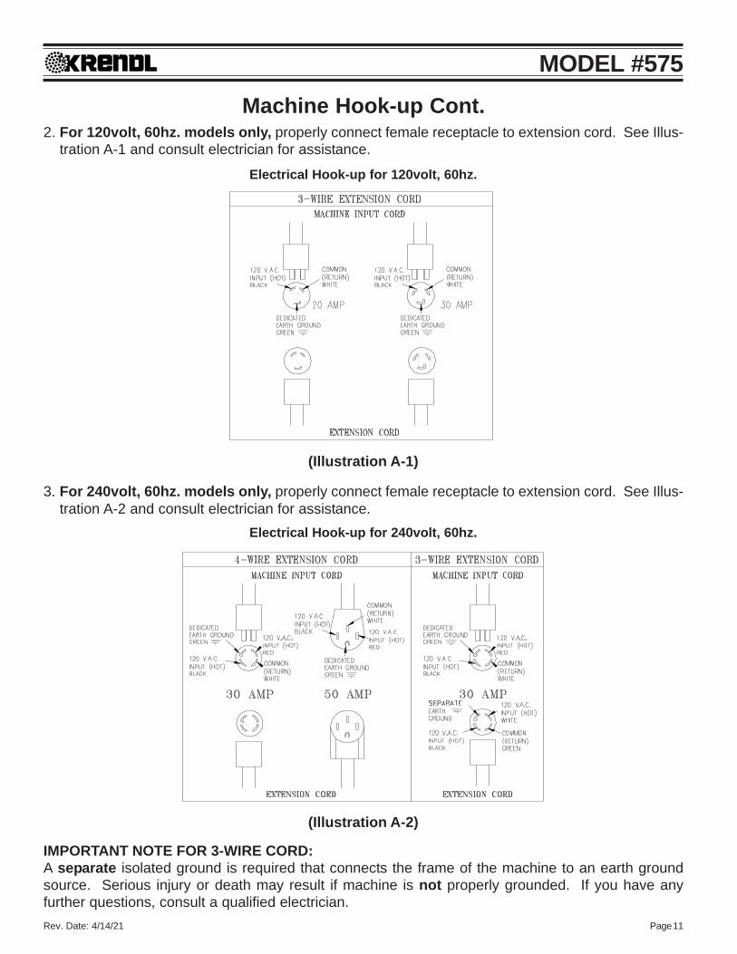
(Illustration A-2)
Electrical Hook-up for 240volt, 60hz.
Machine Hook-up Cont.2. For 120volt, 60hz. models only, properly connect female receptacle to extension cord. See Illus-
tration A-1 and consult electrician for assistance.
3. For 240volt, 60hz. models only, properly connect female receptacle to extension cord. See Illus-tration A-2 and consult electrician for assistance.
IMPORTANT NOTE FOR 3-WIRE CORD:A separate isolated ground is required that connects the frame of the machine to an earth groundsource. Serious injury or death may result if machine is not properly grounded. If you have anyfurther questions, consult a qualified electrician.
(Illustration A-1)
Electrical Hook-up for 120volt, 60hz.

Rev. Date: 4/14/21 Page 12
MODEL #575
Main Control Panel (lid closed)
Electrical OperationPRESS KILL SWITCH TO IMMEDIATELY STOP MACHINE AT ANY TIME!
1. Make sure Kill Switch is out by pulling. (See Illustration B)2. Turn red Main Disconnect Switch to ON position. (See Illustration B)3. Set 4-Position Selector Switch to OFF. (See Illustration B)4. Press green start Button. Machine will not run unless start button is pressed after Kill Switch
is out and red Main Disconnect Switch is on. (See Illustration B)5. Select operating mode on 4-Position Selector Switch from one of the following options:
Remote: Remote control hand pendant will control machine.Off: Machine will not run. (overrides remote hand pendant)Blower: Only the blower will run continuously. (manual control at machine)Agitator-Feed/Blower: Both the blower and the agitator-feed will run continuously.
(manual control at machine)
(Illustration B)
6. When operating in Remote mode, the 4-Position Selector Switch must be set to Remote position.(See Illustration B)
7. Remote control hand pendant positions will be selected from the following:
BLOWER-FEED - operates both blower motor and agitator-feed motor simultaneouslyOFF - (middle position) all functions stopBLOWER - operates the blower motor only
8. If using optional Internal Wetting System (IWS), connect IWS cord to 24 VAC Outlet on MainControl Panel. (See Illustration A)
9. Adjust blower(s) and slidegate to desired settings. (See page 13 and 14)
(Illustration C)
Kill Switch(Pull to release)Start Button(Green)
Alarm4-Position
Selector SwitchHourmeterBlower Control
Main Disconnect Switch (Red)
Voltmeter
Rev. Date: 4/14/21 Page 13
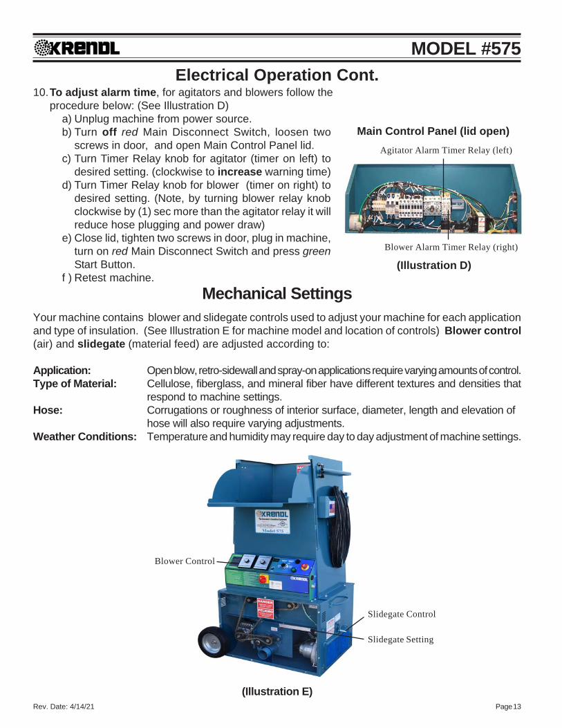
MODEL #575Electrical Operation Cont.
10.To adjust alarm time, for agitators and blowers follow theprocedure below: (See Illustration D)
a) Unplug machine from power source.b) Turn off red Main Disconnect Switch, loosen two
screws in door, and open Main Control Panel lid.c) Turn Timer Relay knob for agitator (timer on left) to
desired setting. (clockwise to increase warning time)d) Turn Timer Relay knob for blower (timer on right) to
desired setting. (Note, by turning blower relay knobclockwise by (1) sec more than the agitator relay it willreduce hose plugging and power draw)
e) Close lid, tighten two screws in door, plug in machine,turn on red Main Disconnect Switch and press greenStart Button.
f ) Retest machine.Mechanical Settings
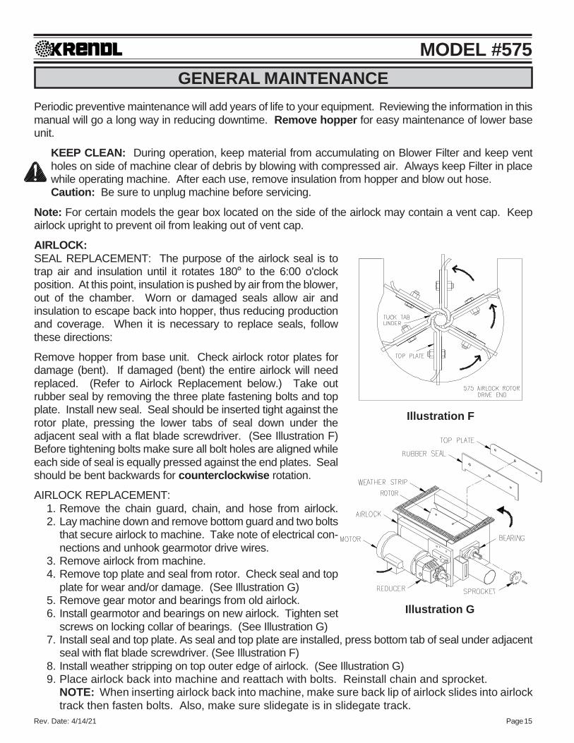
Your machine contains blower and slidegate controls used to adjust your machine for each applicationand type of insulation. (See Illustration E for machine model and location of controls) Blower control(air) and slidegate (material feed) are adjusted according to:
Application: Open blow, retro-sidewall and spray-on applications require varying amounts of control.Type of Material: Cellulose, fiberglass, and mineral fiber have different textures and densities that
respond to machine settings.Hose: Corrugations or roughness of interior surface, diameter, length and elevation of
hose will also require varying adjustments.Weather Conditions: Temperature and humidity may require day to day adjustment of machine settings.
(Illustration E)
Blower Control
Slidegate Control
Slidegate Setting
Main Control Panel (lid open)
(Illustration D)
Agitator Alarm Timer Relay (left)
Blower Alarm Timer Relay (right)

Rev. Date: 4/14/21 Page 14
MODEL #575BLOWER CONTROL AND SLIDEGATE GENERAL SETTINGS:Blower control can increase or decrease the amount of air in the system, affecting the velocity (speed)and spread rate (coverage) of insulation. (See Illustration E) The blower control dial operates clockwise,from HIGH to LOW, controlling air pressure and amount of air.
Opening or closing slidegate (material feed) controls the amount of insulation dropping into the airlockwhich changes the production rate (lbs. per hour). (See Illustration E) For calibration purposes the scalelocated on right side of machine indicates how many inches the airlock slidegate is opened.
The blower and slidegate controls working together affect the distance insulation can be blown througha hose without plugging. These controls also affect the accurate blowing of insulations for sprayingapplications.
These settings control the following:• Density of insulation blown in retro-sidewall application.• Velocity of material impact when spraying.• Dust on open blow.• Material spread rate or coverage.• Production rate (lbs. per hour blown).
GENERAL BLOWER CONTROL AND SLIDEGATE SETTINGS FOR OPEN BLOW:With the slidegate closed, turn agitator-feed motor on and variable speed blower control(s) on low.Fill hopper with insulation and adjust blower control and slidegate. In making adjustments, movecontrols proportional to each other. (i.e. If variable speed blower control is half speed, slidegateshould be half open.) Open slidegate to allow insulation to drop into the airlock providing goodproduction, but not beyond point where hose plugs. As hose length is increased, the blower controlspeed is increased while closing the slidegate proportionally. This will increase the distance insulationcan be blown through the hose and improve material coverage rate, while decreasing the blowingproduction rate (lbs. per hour blown). These adjustments are for open blow. If specialty application orretro sidewall work is done, refer to General Blower/Slidegate Settings chart (below left) or insulationmanufacturer. (See Illustration E)
GENERAL BLOWER/SLIDEGATE SETTINGS:Since specific settings need to be determined by each operator, the following are only suggestedguidelines. Consult the insulation manufacturer for additional recommendations specific to theirproduct.
APPLICATION BLOWER CONTROL SLIDEGATEOpen Blow High Full OpenSidewall-Retrofit Low-Med 1/3 Open -Half OpenWall Cavity Spray Medium Half OpenCommercial Spray (Adhesive) High One-third Open
Rev. Date: 4/14/21 Page 15
MODEL #575GENERAL MAINTENANCE
Periodic preventive maintenance will add years of life to your equipment. Reviewing the information in thismanual will go a long way in reducing downtime. Remove hopper for easy maintenance of lower baseunit.
KEEP CLEAN: During operation, keep material from accumulating on Blower Filter and keep ventholes on side of machine clear of debris by blowing with compressed air. Always keep Filter in placewhile operating machine. After each use, remove insulation from hopper and blow out hose.Caution: Be sure to unplug machine before servicing.
Note: For certain models the gear box located on the side of the airlock may contain a vent cap. Keepairlock upright to prevent oil from leaking out of vent cap.
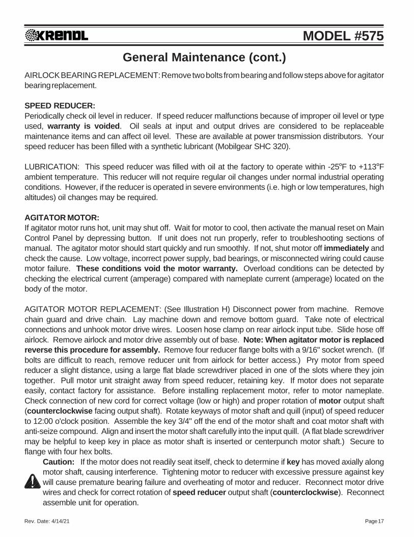
AIRLOCK:SEAL REPLACEMENT: The purpose of the airlock seal is totrap air and insulation until it rotates 180O to the 6:00 o'clockposition. At this point, insulation is pushed by air from the blower,out of the chamber. Worn or damaged seals allow air andinsulation to escape back into hopper, thus reducing productionand coverage. When it is necessary to replace seals, followthese directions:
Remove hopper from base unit. Check airlock rotor plates fordamage (bent). If damaged (bent) the entire airlock will needreplaced. (Refer to Airlock Replacement below.) Take outrubber seal by removing the three plate fastening bolts and topplate. Install new seal. Seal should be inserted tight against therotor plate, pressing the lower tabs of seal down under theadjacent seal with a flat blade screwdriver. (See Illustration F)Before tightening bolts make sure all bolt holes are aligned whileeach side of seal is equally pressed against the end plates. Sealshould be bent backwards for counterclockwise rotation.
AIRLOCK REPLACEMENT:1. Remove the chain guard, chain, and hose from airlock.2. Lay machine down and remove bottom guard and two bolts
that secure airlock to machine. Take note of electrical con-nections and unhook gearmotor drive wires.
3. Remove airlock from machine.4. Remove top plate and seal from rotor. Check seal and top
plate for wear and/or damage. (See Illustration G)5. Remove gear motor and bearings from old airlock.6. Install gearmotor and bearings on new airlock. Tighten set
screws on locking collar of bearings. (See Illustration G)7. Install seal and top plate. As seal and top plate are installed, press bottom tab of seal under adjacent
seal with flat blade screwdriver. (See Illustration F)8. Install weather stripping on top outer edge of airlock. (See Illustration G)9. Place airlock back into machine and reattach with bolts. Reinstall chain and sprocket.
NOTE: When inserting airlock back into machine, make sure back lip of airlock slides into airlocktrack then fasten bolts. Also, make sure slidegate is in slidegate track.
Illustration F
Illustration G

Rev. Date: 4/14/21 Page 16
MODEL #575General Maintenance (cont.)
Make sure seal and top plate are assembled on correct side of rotor plate before assembling inairlock. Seal should press backward towards top plate when installed correctly into airlockchamber. The airlock runs counterclockwise viewing it from the sprocket drive shaft. (SeeIllustration F) Caution: If installed improperly, damage to seals will result and put undue stresson agitator motor. This causes overheating and poor production. Seal should be bent backwardto allow for a counterclockwise rotation of rotor.
CHAIN: (#40 Nickel Plated)ADJUSTMENT: A smooth operating chain drive should have a slight sag on the idler side of the chain.New chains should be installed under slight tension as they will elongate a small amount due toseating of pins and bushings during the first few days of operation. Excessive chain tension or loosechain will cause shortened life of bearings, chain, and sprocket. Chain should be kept in goodcondition by proper lubrication (dry film lubricant Dow 321) and occasional cleaning. Soaking chain incontainer of 10 weight oil will provide for internal lubrication of pins and bushings. However, excess oilmust be drained and wiped away as excessive lubrication will cause insulation accumulation on chain.Worn out chain should be replaced. When chain is replaced, worn sprockets should also be replaced,preventing further damage to new chain.
SPROCKETS:CHECK SPROCKETS FOR WEAR. Misalignment and/or loose sprockets and improper chaintension causes the premature wear of chain and sprockets. All sprockets, except the idler sprocket,have been secured with a medium grade Loctite (general purpose thread locker), to prevent gradualmovement. The set screws and key are also inserted with a medium grade Loctite. If sprocket isdifficult to remove, it may be heated with a propane torch to loosen.
Caution: Do not overheat sprocket or damage to bearing will result. A pulley or bearing puller canthen be used to remove the sprocket and key. Replace new sprocket on shaft with key and mediumgrade Loctite applied to shaft. Align sprocket with corresponding sprocket, using a straightedgeplaced along face of teeth and tighten set screw. Gearmotor sprocket does not require Loctite.
BEARINGS:AGITATOR BEARINGS in base unit are prelubricated, double-sealed, self aligning ball bearings. Nolubrication is necessary. If bearings produce noise or heat (too-hot-to-touch), replace the bearings.
AGITATOR BEARING REPLACEMENT: Spray area with rust penetrant (WD-40). Remove sprocket(See SPROCKET section above). Remove the two bolts from bearing flange and outer flange frombearing insert. Loosen set screws on bearing hub at each end of agitator shaft. Since all set screws areinstalled with a medium grade Locktite, a propane hand torch may be used to assist in removing them.Do not overheat unit, causing shaft to expand. Using a rubber mallet, drive agitator shaft an inch in onedirection, creating a space between hopper and bearing unit. A bearing puller can then be used toremove the bearing. Eliminate any metal burrs from shaft with file and install new bearings with feltseals. Use a medium grade Loctite on set screws before securing bearing to shaft.
AIRLOCK BEARINGS are prelubricated, double sealed, self aligning ball bearings. Lubrication isrequired at three month intervals of normal running time, or sooner if bearings produce a noise orbecome too-hot-to-touch. Relubrication at the grease fittings is done with a lithium base greaseconforming to a NLGI GRADE TWO consistency. The grease should be pumped in slowly until a slightbead forms around the seals. This bead, in addition to acting as an indicator of adequate lubrication,provides additional protection against the entry of foreign matter. Important: If a slight bead does notform, indicating a failure of lubrication, or if bearing shows signs of wear, replace bearing.
Rev. Date: 4/14/21 Page 17
MODEL #575General Maintenance (cont.)
AIRLOCK BEARING REPLACEMENT: Remove two bolts from bearing and follow steps above for agitatorbearing replacement.
SPEED REDUCER:Periodically check oil level in reducer. If speed reducer malfunctions because of improper oil level or typeused, warranty is voided. Oil seals at input and output drives are considered to be replaceablemaintenance items and can affect oil level. These are available at power transmission distributors. Yourspeed reducer has been filled with a synthetic lubricant (Mobilgear SHC 320).
LUBRICATION: This speed reducer was filled with oil at the factory to operate within -25OF to +113OFambient temperature. This reducer will not require regular oil changes under normal industrial operatingconditions. However, if the reducer is operated in severe environments (i.e. high or low temperatures, highaltitudes) oil changes may be required.
AGITATOR MOTOR:If agitator motor runs hot, unit may shut off. Wait for motor to cool, then activate the manual reset on MainControl Panel by depressing button. If unit does not run properly, refer to troubleshooting sections ofmanual. The agitator motor should start quickly and run smoothly. If not, shut motor off immediately andcheck the cause. Low voltage, incorrect power supply, bad bearings, or misconnected wiring could causemotor failure. These conditions void the motor warranty. Overload conditions can be detected bychecking the electrical current (amperage) compared with nameplate current (amperage) located on thebody of the motor.
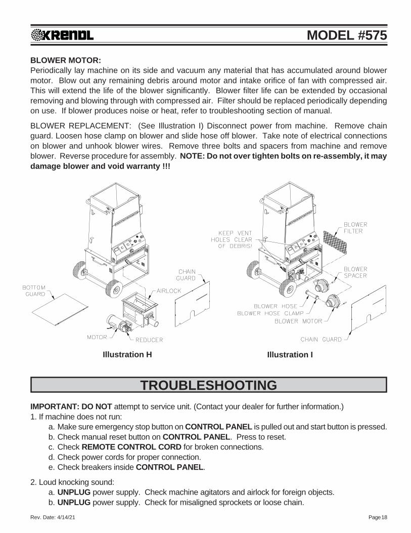
AGITATOR MOTOR REPLACEMENT: (See Illustration H) Disconnect power from machine. Removechain guard and drive chain. Lay machine down and remove bottom guard. Take note of electricalconnections and unhook motor drive wires. Loosen hose clamp on rear airlock input tube. Slide hose offairlock. Remove airlock and motor drive assembly out of base. Note: When agitator motor is replacedreverse this procedure for assembly. Remove four reducer flange bolts with a 9/16" socket wrench. (Ifbolts are difficult to reach, remove reducer unit from airlock for better access.) Pry motor from speedreducer a slight distance, using a large flat blade screwdriver placed in one of the slots where they jointogether. Pull motor unit straight away from speed reducer, retaining key. If motor does not separateeasily, contact factory for assistance. Before installing replacement motor, refer to motor nameplate.Check connection of new cord for correct voltage (low or high) and proper rotation of motor output shaft(counterclockwise facing output shaft). Rotate keyways of motor shaft and quill (input) of speed reducerto 12:00 o'clock position. Assemble the key 3/4" off the end of the motor shaft and coat motor shaft withanti-seize compound. Align and insert the motor shaft carefully into the input quill. (A flat blade screwdrivermay be helpful to keep key in place as motor shaft is inserted or centerpunch motor shaft.) Secure toflange with four hex bolts.
Caution: If the motor does not readily seat itself, check to determine if key has moved axially alongmotor shaft, causing interference. Tightening motor to reducer with excessive pressure against keywill cause premature bearing failure and overheating of motor and reducer. Reconnect motor drivewires and check for correct rotation of speed reducer output shaft (counterclockwise). Reconnectassemble unit for operation.
Rev. Date: 4/14/21 Page 18
MODEL #575
Illustration H Illustration I
BLOWER MOTOR:Periodically lay machine on its side and vacuum any material that has accumulated around blowermotor. Blow out any remaining debris around motor and intake orifice of fan with compressed air.This will extend the life of the blower significantly. Blower filter life can be extended by occasionalremoving and blowing through with compressed air. Filter should be replaced periodically dependingon use. If blower produces noise or heat, refer to troubleshooting section of manual.
BLOWER REPLACEMENT: (See Illustration I) Disconnect power from machine. Remove chainguard. Loosen hose clamp on blower and slide hose off blower. Take note of electrical connectionson blower and unhook blower wires. Remove three bolts and spacers from machine and removeblower. Reverse procedure for assembly. NOTE: Do not over tighten bolts on re-assembly, it maydamage blower and void warranty !!!
TROUBLESHOOTINGIMPORTANT: DO NOT attempt to service unit. (Contact your dealer for further information.)1. If machine does not run:
a. Make sure emergency stop button on CONTROL PANEL is pulled out and start button is pressed.b. Check manual reset button on CONTROL PANEL. Press to reset.c. Check REMOTE CONTROL CORD for broken connections.d. Check power cords for proper connection.e. Check breakers inside CONTROL PANEL.
2. Loud knocking sound:a. UNPLUG power supply. Check machine agitators and airlock for foreign objects.b. UNPLUG power supply. Check for misaligned sprockets or loose chain.
Rev. Date: 4/14/21 Page 19
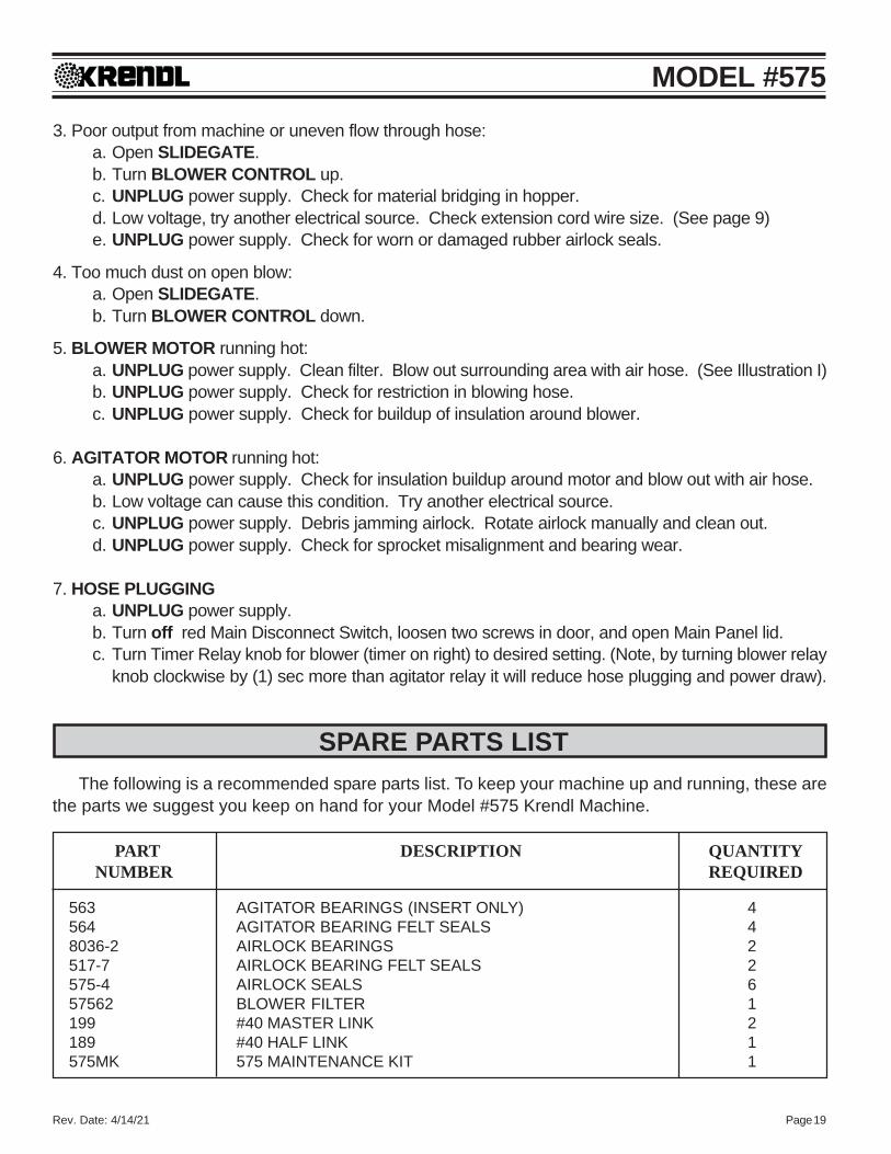
MODEL #5753. Poor output from machine or uneven flow through hose:
a. Open SLIDEGATE.b. Turn BLOWER CONTROL up.c. UNPLUG power supply. Check for material bridging in hopper.d. Low voltage, try another electrical source. Check extension cord wire size. (See page 9)e. UNPLUG power supply. Check for worn or damaged rubber airlock seals.
4. Too much dust on open blow:a. Open SLIDEGATE.b. Turn BLOWER CONTROL down.
5. BLOWER MOTOR running hot:a. UNPLUG power supply. Clean filter. Blow out surrounding area with air hose. (See Illustration I)b. UNPLUG power supply. Check for restriction in blowing hose.c. UNPLUG power supply. Check for buildup of insulation around blower.
6. AGITATOR MOTOR running hot:a. UNPLUG power supply. Check for insulation buildup around motor and blow out with air hose.b. Low voltage can cause this condition. Try another electrical source.c. UNPLUG power supply. Debris jamming airlock. Rotate airlock manually and clean out.d. UNPLUG power supply. Check for sprocket misalignment and bearing wear.
7. HOSE PLUGGINGa. UNPLUG power supply.b. Turn off red Main Disconnect Switch, loosen two screws in door, and open Main Panel lid.c. Turn Timer Relay knob for blower (timer on right) to desired setting. (Note, by turning blower relay
knob clockwise by (1) sec more than agitator relay it will reduce hose plugging and power draw).
PART DESCRIPTION QUANTITYNUMBER REQUIRED
563 AGITATOR BEARINGS (INSERT ONLY) 4564 AGITATOR BEARING FELT SEALS 48036-2 AIRLOCK BEARINGS 2517-7 AIRLOCK BEARING FELT SEALS 2575-4 AIRLOCK SEALS 657562 BLOWER FILTER 1199 #40 MASTER LINK 2189 #40 HALF LINK 1575MK 575 MAINTENANCE KIT 1
SPARE PARTS LISTThe following is a recommended spare parts list. To keep your machine up and running, these are
the parts we suggest you keep on hand for your Model #575 Krendl Machine.

MODEL #575
MODEL #575120 V.A.C. 60 Hz
Double Input(Single Blower)
ELECTRICAL DIAGRAM:Periodically, disconnect machine from power source and check all electrical connections and components for broken or loose wires.
ELECTRICAL
Rev. Date: 4/14/21 Page 20
MODEL #575
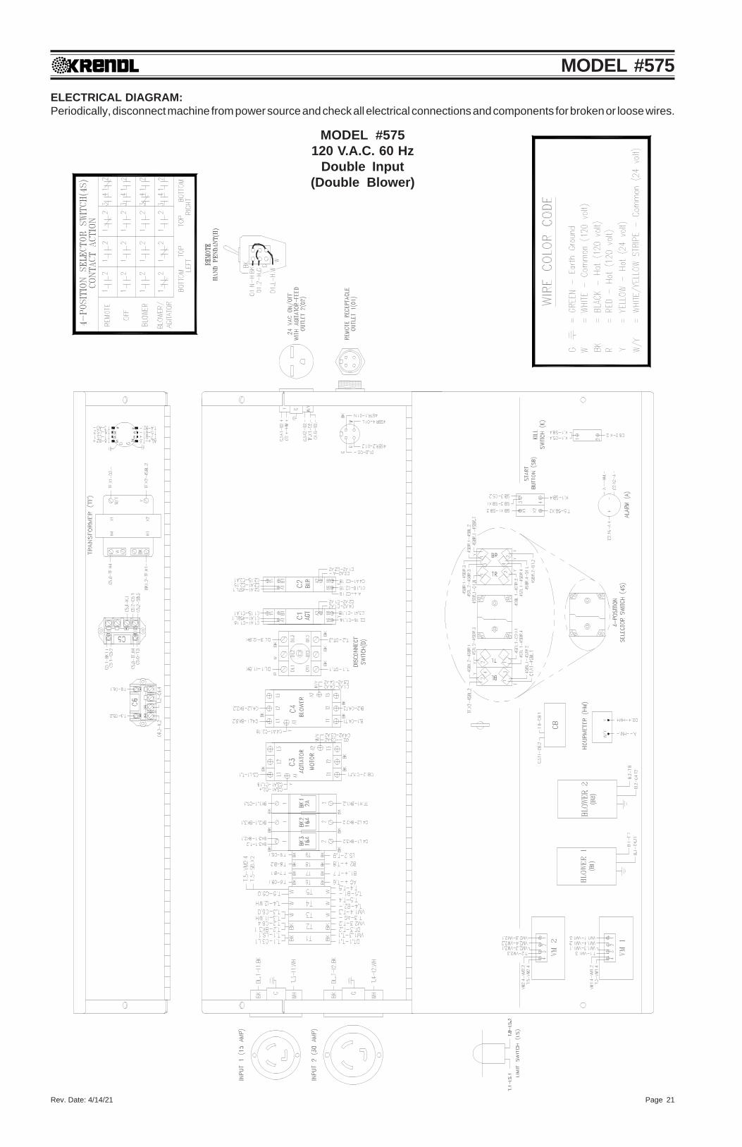
MODEL #575120 V.A.C. 60 Hz
Double Input(Double Blower)
ELECTRICAL DIAGRAM:Periodically, disconnect machine from power source and check all electrical connections and components for broken or loose wires.
Rev. Date: 4/14/21 Page 21

MODEL #575
MODEL #575240 V.A.C. 60 Hz
Single Input(Double Blower)
ELECTRICAL DIAGRAM:Periodically, disconnect machine from power source and check all electrical connections and components for broken or loose wires.
Rev. Date: 4/14/21 Page 22

MODEL #575
MODEL #575230 V.A.C. 50 Hz
Double Input(Double Blower)
ELECTRICAL DIAGRAM:Periodically, disconnect machine from power source and check all electrical connections and components for broken or loose wires.
Rev. Date: 4/14/21 Page 23

Rev. Date: 4/14/21 Page 24
MODEL #575
LADDER DIAGRAM120 VOLT 60 HZDOUBLE INPUT
(SINGLE BLOWER)
Rev. Date: 4/14/21 Page 25
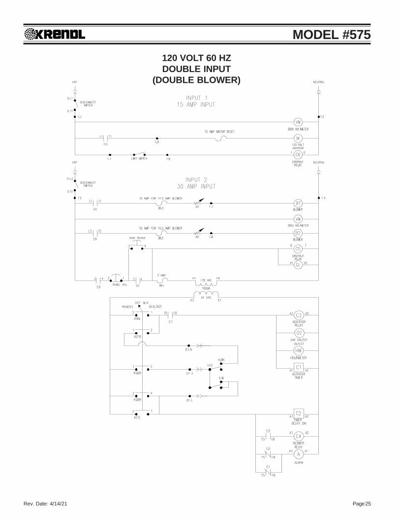
MODEL #575120 VOLT 60 HZDOUBLE INPUT
(DOUBLE BLOWER)

Rev. Date: 4/14/21 Page 26
MODEL #575240 VOLT 60 HZSINGLE INPUT
(DOUBLE BLOWER)

Rev. Date: 4/14/21 Page 27
MODEL #575230 VOLT 50 HZDOUBLE INPUT
(DOUBLE BLOWER)

Rev. Date: 4/14/21 Page 28
MODEL #575EXPLODED PARTS
#575 Machine

Rev. Date: 4/14/21 Page 29
MODEL #575
#575 PARTS LISTItem # Part # Description
1 575-5-R4 Base2 575-9 Hopper3 23-99 Latch, Pull (2)4 575-7 Agitator (2)
5-1 565 Housing, Flange, 2-Bolt 1" Stamped (8)5-2 563 Bearing, 1" Bore (4) Insert Only6 564 Seal, Felt, 1" (4)7 57562 Filter, Blower 16" x 78 S-40B15-B #40 Sprocket, 15T x 1" (2) (U.S)8 S-40BS18T1 #40 Sprocket, 18T x 1" (2) (Overseas)9 561Z Key, 1/4" x 1/4" x 1" (3)
10 408-G Blower Motor, 14 Amp, 2-Stage (2)11 408-J Blower Motor, 7 Amp, (2) Overseas12 409-F Spacer, 2 3/16" Blower (6) (only 2 shown)13 337 Clamp, 2" Hose (6)
13-1 339 Clamp, 2 1/2" Hose (2)14 407 2" Hose, 12" long15 406 2" Hose, 20" long16 42572 2" Hose, 1" long
16-1 25-16 2 1/2" Hose, 3" long17 CV101 Check Valve (2)18 568 Check Valve Y-Tube (Double Blower Option)18 357 Reducer, 2 1/2" to 2" (Single Blower Option)19 575-20 Support, Hose20 113-AC Gasket, 2", STD 3/16" (2)
21-1 FSB037 SB 5/16-18 x 7/8" HMS (4)21-2 FW008 Lock Washer, 5/16" (4)21-3 FW007 Flat Washer, 5/16" (4)22 575-10 Guard, Bottom23 575-15-P Guard, Chain
24-1 575-1-R2 Airlock Chamber with Rotor24-2 575-3 Plate, Top Airlock (6)24-3 575-4 Seal, Airlock (6)24-4 517-7 Seal, Felt, 1" (2)24-5 8036-2 Bearing, 2 Bolt , 1" (2)25 40NP-57 Chain, #40 x 57" (U.S.)25 109019-14 Chain, #40 x 58" (Overseas)26 42537 Chain, #40 x 27" (U.S.)26 40NP-28 Chain. #40 x 28" (Overseas)---- 199 Master Link, #40 (2) (not shown)---- 189 Half Link, #40 (1) (not shown)27 432 Sprocket, Idler, #40 17T x 5/8" (2)
27-1 FSB120 SB 5/8" x 3/4" Shoulder Bolt27-2 40052 Nut, 1" x 1/2" (1/2-13), Plated (2)

Rev. Date: 4/14/21 Page 30
MODEL #57527-3 FSB092 SB 5/8" x 1" Shoulder Bolt28 575-6-R1 Slidegate29 475-8 Crankrod30 4507 Handle f/Crankrod31 FN015 Lock Nut, 3/8"-1632 575-21 Motor & Cord Assy, 1HP, 120V 60Hz (U.S.)32 575-22 Motor & Cord Assy, 1HP, 240V 60Hz (U.S.)32 594-ASSY Motor & Cord Assy, 1HP, 230V 50Hz (Overseas)
32-1 547 Motor, 1HP, 120V & 240V 60Hz32-1 594 Motor, 1HP, 230V 50Hz32-2 575GB Gearbox, In-Line33 475-20 #40, Sprocket, 15T x 24T x 1" (U.S.)33 514-6 #40, Sprocket, 18T x 28T x 1" (Overseas)
33-1 562Z Key, 1/4" x 1/4" x 1 1/4"34 S-40B15-B #40, Sprocket, 15T x 1" w/hub35 575-11 Axle,Wheel36 57565 Pin, Cotter, 1/8" x 1 1/2" (2)37 W-12 Wheel, Flat Free, 3/4" (2)
37-1 FW030 W 3/4 Flat Washer-SAE (4)38 ELU13-KT-0475 Electrical Upgrade (120V, 60 Hz.) (double input, single 14 A blower)39 ELU12-KT-0575DL Electrical Upgrade (120V, 60 Hz.) (double input, double 14 A blower)
39-1 ELU12-KT-0575SH Electrical Upgrade (240V, 60 Hz.) (single input, double 14 A blower)39-2 ELU13-KT-0575DHCE Electrical Upgrade (230V, 50 Hz.) (double input, double 14 A blower)40 RC395-K RC Cord Assy, 4 Pin Connector, 150'41 RC395-DPDT RC Service Kit (DPDT)
41-1 RC395-1 Switch Housing41-2 RC395-2 Switch Housing Cover with belt clip41-3 1536-7 Belt Clip41-4 109066-9 Switch, Toggle, DPDT41-5 1536-4 Strain Relief41-6 RC395-4 8-16 Plastic Screws (4) (Not Shown)42 18-4 SJ Wire, 18-4 SJ (150')43 487 Connector, 4 Pin, Male44 LS100 Flush Mount, Limit Switch45 575-40 Electrical Guard

Rev. Date: 4/14/21 Page 31
MODEL #575
HOURMETER
MOTOR
RESET
ALARM
START
VOLTMETER INPUT
EMERGENCY
STOP
VOLTMETER INPUT
VARIABLE SPEED
BLOWER CONTROL
OFF
REMOTECONTROL
BLOWER
BLOWERAGITATOR/
REMOTE MANUAL
DescriptionBlower Control (120V, 60Hz.) (2)Cover, Blower Control (2)Knob, Blower Control (2)Switch, Kill, RedContact Block (Kill Switch not shown)Hour MeterManual Reset, 15 AmpTimer / Relay DPDT 12-240VAC 15A (2)Contactor / Relay 25 Amp (2)Relay, Contactor/Relay, 120V Control (2)Transformer, 4 AmpBreaker, 16 Amp (2)Breaker, 2 AmpTerminal Block, Small (3)Terminal Block, Large (5)
ELECTRICAL PARTS LIST120 V.A.C. 60 Hz. D.I (SINGLE BLOWER)
DescriptionBox, ElectricalReceptacle, NEMA #6-15RConnector, 4 Pin Female (remote)Pre-Alarm SystemPlug, Recessed Input 5-15P (2)Voltmeter, Digital 120V (2)Dinrail, 1 3/8", 16" LongClamp, f/ 1 3/8" Din Rail (2)Switch, Disconnect Assy 3PSwitch, 4-Position SelectorContact Block, Selector Switch(white) #KA-1 (not shown)Contact Block, Selector Switch(red) #KA-3 (3) (not shown)Pushbutton On, GreenContact Block 22mm Green(Pushbutton not shown)
Item#38-138-238-338-438-538-638-738-838-938-1038-11
38-12
38-1338-14
Part#475-23-R1
132-B491
543-M-3842528
543-M-83ELU12-A
151080-49600-R-01543-M-22543-M-15
543-M-16
543-M-148075-2
Electrical Exploded Parts ListItem#38-1538-1638-1738-1838-1938-2038-2138-2238-2338-2438-2538-2638-2738-2838-29
Part#419-A420-1420-2508-28075-1
543-M-77433-E
RELAY-10ELU11-5-AELU10-10
1530-DBRKR-16BRKR-2
151080-61151080-62
Rev. Date: 4/14/21 Page 32
MODEL #575
BLOWER CONTROL
VARIABLE SPEED VARIABLE SPEED
BLOWER CONTROL
OFF
REMOTECONTROL
BLOWER
BLOWERAGITATOR/
REMOTE MANUAL
HOURMETER
MOTOR
RESET
ALARM
START
VOLTMETER INPUT1
VOLTMETER INPUT2
EMERGENCY
STOP
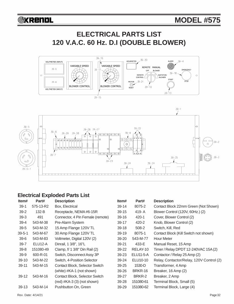
DescriptionContact Block 22mm Green (Not Shown)Blower Control (120V, 60Hz.) (2)Cover, Blower Control (2)Knob, Blower Control (2)Switch, Kill, RedContact Block (Kill Switch not shown)Hour MeterManual Reset, 15 AmpTimer / Relay DPDT 12-240VAC 15A (2)Contactor / Relay 25 Amp (2)Relay, Contactor/Relay, 120V Control (2)Transformer, 4 AmpBreaker, 16 Amp (2)Breaker, 2 AmpTerminal Block, Small (5)Terminal Block, Large (4)
DescriptionBox, ElectricalReceptacle, NEMA #6-15RConnector, 4 Pin Female (remote)Pre-Alarm System15 Amp Flange 120V TL30 Amp Flange 120V TLVoltmeter, Digital 120V (2)Dinrail, 1 3/8", 16"LClamp, f/ 1 3/8" Din Rail (2)Switch, Disconnect Assy 3PSwitch, 4-Position SelectorContact Block, Selector Switch(white) #KA-1 (not shown)Contact Block, Selector Switch(red) #KA-3 (3) (not shown)Pushbutton On, Green
ELECTRICAL PARTS LIST120 V.A.C. 60 Hz. D.I (DOUBLE BLOWER)
Item#39-139-239-339-439-5
39-5-139-639-739-839-939-1039-11
39-12
39-13
Part#575-13-R2
132-B491
543-M-38543-M-32543-M-67543-M-83ELU12-A
151080-49600-R-01543-M-22543-M-15
543-M-16
543-M-14
Electrical Exploded Parts ListItem#39-1439-1539-1639-1739-1839-1939-2039-2139-2239-2339-2439-2539-2639-2739-2839-29
Part#8075-2419- A420-1420-2508-28075-1
543-M-77433-E
RELAY-10ELU11-5-AELU10-10
1530-DBRKR-16BRKR-2
151080-61151080-62
Rev. Date: 4/14/21 Page 33
MODEL #575
BLOWER CONTROL
VARIABLE SPEED VARIABLE SPEED
BLOWER CONTROL
OFF
REMOTECONTROL
BLOWER
BLOWERAGITATOR/
REMOTE MANUAL
HOURMETER
MOTOR
RESET
ALARM
START
VOLTMETER INPUT1
EMERGENCY
STOP
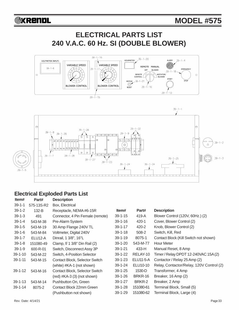
DescriptionBlower Control (120V, 60Hz.) (2)Cover, Blower Control (2)Knob, Blower Control (2)Switch, Kill, RedContact Block (Kill Switch not shown)Hour MeterManual Reset, 8 AmpTimer / Relay DPDT 12-240VAC 15A (2)Contactor / Relay 25 Amp (2)Relay, Contactor/Relay, 120V Control (2)Transformer, 4 AmpBreaker, 16 Amp (2)Breaker, 2 AmpTerminal Block, Small (5)Terminal Block, Large (4)
ELECTRICAL PARTS LIST240 V.A.C. 60 Hz. SI (DOUBLE BLOWER)
DescriptionBox, ElectricalReceptacle, NEMA #6-15RConnector, 4 Pin Female (remote)Pre-Alarm System30 Amp Flange 240V TLVoltmeter, Digital 240VDinrail, 1 3/8", 16"LClamp, f/ 1 3/8" Din Rail (2)Switch, Disconnect Assy 3PSwitch, 4-Position SelectorContact Block, Selector Switch(white) #KA-1 (not shown)Contact Block, Selector Switch(red) #KA-3 (3) (not shown)Pushbutton On, GreenContact Block 22mm Green(Pushbutton not shown)
Item#39-1-139-1-239-1-339-1-439-1-539-1-639-1-739-1-839-1-939-1-1039-1-11
39-1-12
39-1-1339-1-14
Part#575-13S-R2
132-B491
543-M-38543-M-19543-M-84ELU12-A
151080-49600-R-01543-M-22543-M-15
543-M-16
543-M-148075-2
Electrical Exploded Parts List
Item#39-1-1539-1-1639-1-1739-1-1839-1-1939-1-2039-1-2139-1-2239-1-2339-1-2439-1-2539-1-2639-1-2739-1-2839-1-29
Part#419-A420-1420-2508-28075-1
543-M-77433-H
RELAY-10ELU11-5-AELU10-10
1530-DBRKR-16BRKR-2
151080-61151080-62

Rev. Date: 4/14/21 Page 34
MODEL #575
BLOWER CONTROL
VARIABLE SPEED VARIABLE SPEED
BLOWER CONTROL
OFF
REMOTECONTROL
BLOWER
BLOWERAGITATOR/
REMOTE MANUAL
HOURMETER
MOTOR
RESET
ALARM
START
VOLTMETER INPUT1
VOLTMETER INPUT2
EMERGENCY
STOP
ELECTRICAL PARTS LIST230 V.A.C. 50 Hz. DI (DOUBLE BLOWER)
DescriptionBox, ElectricalReceptacle, NEMA #5-15RConnector, 4 Pin Female (remote)Pre-Alarm SystemCover, Transformer (not shown)Voltmeter, Digital 240V (2)Dinrail, 1 3/8", 16"LClamp, f/ 1 3/8" Din Rail (2)Switch, DisconnectOperator Handle AssySwitch, 4-Position SelectorContact Block, Selector Switch(white) #KA-1 (not shown)Contact Block, Selector Switch(red) #KA-3 (3) (not shown)Pushbutton On, GreenBlower Control (230V, 50Hz.) (2)Cover, Blower Control (2)
Item#39-2-139-2-239-2-339-2-439-2-539-2-639-2-739-2-839-2-9
39-2-9-139-2-1039-2-11
39-2-12
39-2-1339-2-1439-2-15
Part#575-13OS-R2
1544491
543-M- 38ELU06-1543-M-84ELU12-A
151080-49600-B-01
54-M-33-OS543-M-22543-M-15
543-M-16
543-M-86419-B420-1
Electrical Exploded Parts ListItem#
39-2-1639-2-1739-2-1839-2-1939-2-2039-2-2139-2-2239-2-2339-2-2439-2-2539-2-2639-2-2739-2-2839-2-2939-2-3039-2-3139-2-32
Part#420-2508-2
8075-1543-M-77
433-HRELAY-10ELU11-5-AELU10-12
1530-DBRKR-8BRKR-1
151080-61151080-62543-M-17391N-A-312-3-SJ-MELU06-9
DescriptionKnob, Blower Control (2)Switch, Kill, RedContact Block (Kill Switch not shown)Hour MeterManual Reset, 8 AmpTimer / Relay DPDT 12-240VAC 15A (2)Contactor / Relay 25 Amp (2)Relay, E-Mech,Control 230V, DPDY-NO(2)Transformer, 4 AmpBreaker, 8 Amp (2)Breaker, 1 AmpTerminal Block, Small (4)Terminal Block, Large (5)Connector, Conduit, 1/2" StraightLocknut, Steel, Conduit, 1/2" (not shown)12-3 SJ w/Brown/Blue/Green/YellowPlug, European
Rev. Date: 4/14/21 Page 35
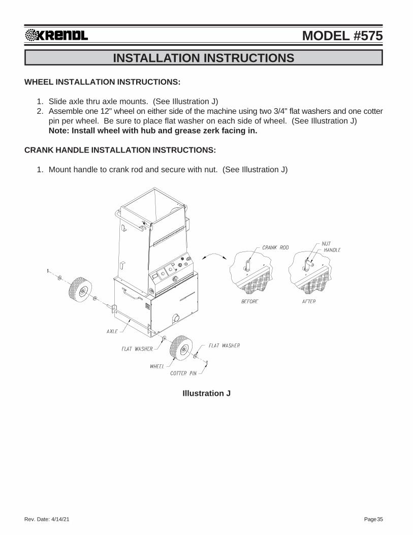
MODEL #575INSTALLATION INSTRUCTIONS
WHEEL INSTALLATION INSTRUCTIONS:
1. Slide axle thru axle mounts. (See Illustration J)2. Assemble one 12" wheel on either side of the machine using two 3/4" flat washers and one cotter
pin per wheel. Be sure to place flat washer on each side of wheel. (See Illustration J)Note: Install wheel with hub and grease zerk facing in.
CRANK HANDLE INSTALLATION INSTRUCTIONS:
1. Mount handle to crank rod and secure with nut. (See Illustration J)
Illustration J
Rev. Date: 4/14/21 Page 36
MODEL #575GLOSSARY
BRIDGING Tendency of insulation to cling in the hopper forming an air pocket abovethe airlock. This hinders the normal feeding process of the machine.
CFM (Cubic feet per minute). A measurement of volume or quantity of airflowing at a certain rate, or air moving capability, of a blower. It is thevolume of air moved per minute. Higher volume provides increasedcoverage and velocity of insulation as it leaves the hose.
COVERAGE Refers to the amount of insulation coverage, usually measured in squarefeet, according to the R-value desired. This information is given on theinsulation package.
PSI (Pounds of pressure per square inch). The force exerted on a surface byair/liquid. High-pressure blowers push the insulation through the hose.Higher pressure provides less hose plugging and increased compaction inside wall.
PRODUCTION RATE Pounds of insulation blown per hour.
RPM (Revolutions per minute). Speed at which the shaft of a rotating device(i.e. blower fan, agitator) is moving.
R-VALUE Resistance value. A precise measurement of the insulation's resistanceto heat transfer. The higher the resistance value, the slower the heat willtransfer through the insulating material.
SETTLED DENSITY The point at which the insulation will not continue to settle further. Anyinsulation blown will have a certain amount of progressive settling thatoccurs after a period of time. Following the insulation manufacturersrecommendations for bag rate coverage will provide useful information toaccommodate for settling.
SETTLING Compression or compaction of insulation fibers caused by the weight ofthe material, vibration of structure, temperature, and humidity cycles.

Rev. Date: 4/14/21 Page 37
MODEL #575SERVICE RECORD
DATE MAINTENANCE PERFORMED COMPONENTS REQUIRED

KRENDL MACHINE COMPANY • 1201 SPENCERVILLE RDDELPHOS, OHIO 45833 • TELEPHONE 800-459-2069 • FAX 419-695-9301
E - MAIL: [email protected] • WEB SITE: www.krendlmachine.com
60 YEARSOF AMERICAN INGENUITY
Made in the U.S.A.