Embed Size (px)
Citation preview
Zevenhoven & Kilpinen PARTICULATES 12.6.2001 5-32
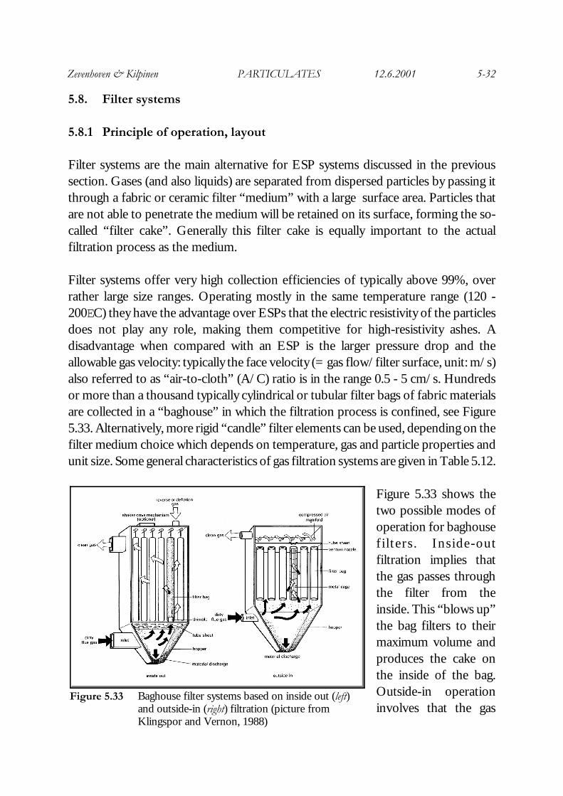
Figure 5.33 Baghouse filter systems based on inside out (left)and outside-in (right) filtration (picture fromKlingspor and Vernon, 1988)
5.8. Filter systems
5.8.1 Principle of operation, layout
Filter systems are the main alternative for ESP systems discussed in the previoussection. Gases (and also liquids) are separated from dispersed particles by passing itthrough a fabric or ceramic filter “medium” with a large surface area. Particles thatare not able to penetrate the medium will be retained on its surface, forming the so-called “filter cake”. Generally this filter cake is equally important to the actualfiltration process as the medium.
Filter systems offer very high collection efficiencies of typically above 99%, overrather large size ranges. Operating mostly in the same temperature range (120 -200EC) they have the advantage over ESPs that the electric resistivity of the particlesdoes not play any role, making them competitive for high-resistivity ashes. Adisadvantage when compared with an ESP is the larger pressure drop and theallowable gas velocity: typically the face velocity (= gas flow/filter surface, unit: m/s)also referred to as “air-to-cloth” (A/C) ratio is in the range 0.5 - 5 cm/s. Hundredsor more than a thousand typically cylindrical or tubular filter bags of fabric materialsare collected in a “baghouse” in which the filtration process is confined, see Figure5.33. Alternatively, more rigid “candle” filter elements can be used, depending on thefilter medium choice which depends on temperature, gas and particle properties andunit size. Some general characteristics of gas filtration systems are given in Table 5.12.
Figure 5.33 shows thetwo possible modes ofoperation for baghousefi l ters . Inside-outfiltration implies thatthe gas passes throughthe filter from theinside. This “blows up”the bag filters to theirmaximum volume andproduces the cake onthe inside of the bag.Outside-in operationinvolves that the gas
Zevenhoven & Kilpinen PARTICULATES 12.6.2001 5-33
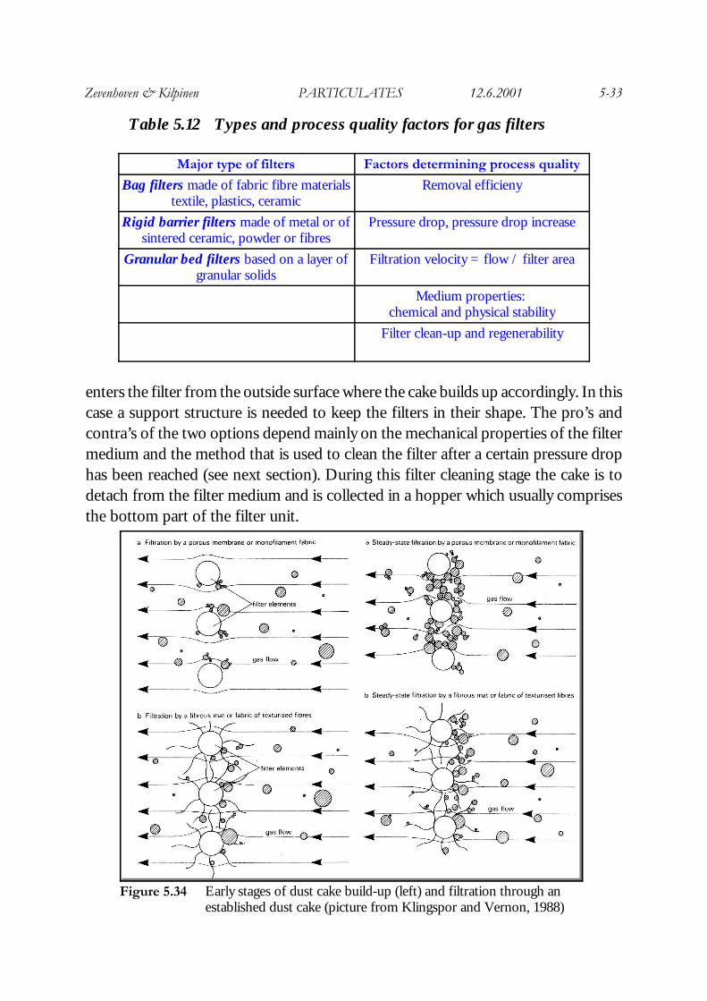
Figure 5.34 Early stages of dust cake build-up (left) and filtration through anestablished dust cake (picture from Klingspor and Vernon, 1988)
Table 5.12 Types and process quality factors for gas filters
Major type of filters Factors determining process quality
Bag filters made of fabric fibre materialstextile, plastics, ceramic
Removal efficieny
Rigid barrier filters made of metal or ofsintered ceramic, powder or fibres
Pressure drop, pressure drop increase
Granular bed filters based on a layer ofgranular solids
Filtration velocity = flow / filter area
Medium properties: chemical and physical stability
Filter clean-up and regenerability
enters the filter from the outside surface where the cake builds up accordingly. In thiscase a support structure is needed to keep the filters in their shape. The pro’s andcontra’s of the two options depend mainly on the mechanical properties of the filtermedium and the method that is used to clean the filter after a certain pressure drophas been reached (see next section). During this filter cleaning stage the cake is todetach from the filter medium and is collected in a hopper which usually comprisesthe bottom part of the filter unit.
Zevenhoven & Kilpinen PARTICULATES 12.6.2001 5-34
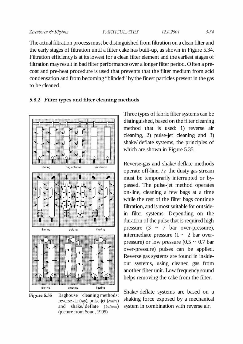
Figure 5.35 Baghouse cleaning methods:reverse-air (top), pulse-jet (centre)and shake/deflate (bottom)(picture from Soud, 1995)
The actual filtration process must be distinguished from filtration on a clean filter andthe early stages of filtration until a filter cake has built-up, as shown in Figure 5.34.Filtration efficiency is at its lowest for a clean filter element and the earliest stages offiltration may result in bad filter performance over a longer filter period. Often a pre-coat and pre-heat procedure is used that prevents that the filter medium from acidcondensation and from becoming “blinded” by the finest particles present in the gasto be cleaned.
5.8.2 Filter types and filter cleaning methods
Three types of fabric filter systems can bedistinguished, based on the filter cleaningmethod that is used: 1) reverse aircleaning, 2) pulse-jet cleaning and 3)shake/deflate systems, the principles ofwhich are shown in Figure 5.35.
Reverse-gas and shake/deflate methodsoperate off-line, i.e. the dusty gas streammust be temporarily interrupted or by-passed. The pulse-jet method operateson-line, cleaning a few bags at a timewhile the rest of the filter bags continuefiltration, and is most suitable for outside-in filter systems. Depending on theduration of the pulse that is required highpressure (3 ~ 7 bar over-pressure),intermediate pressure (1 ~ 2 bar over-pressure) or low pressure (0.5 ~ 0.7 barover-pressure) pulses can be applied.Reverse gas systems are found in inside-out systems, using cleaned gas fromanother filter unit. Low frequency soundhelps removing the cake from the filter.
Shake/deflate systems are based on ashaking force exposed by a mechanicalsystem in combination with reverse air.
Zevenhoven & Kilpinen PARTICULATES 12.6.2001 5-35
Figure 5.36 A shake/deflate baghouse filter(picture from Klingspor andVernon, 1988)
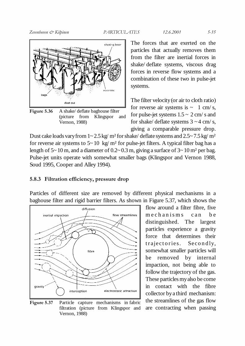
Figure 5.37 Particle capture mechanisms in fabricfiltration (picture from Klingspor andVernon, 1988)
The forces that are exerted on theparticles that actually removes themfrom the filter are inertial forces inshake/deflate systems, viscous dragforces in reverse flow systems and acombination of these two in pulse-jetsystems.
The filter velocity (or air to cloth ratio)for reverse air systems is ~ 1 cm/s,for pulse-jet systems 1.5 ~ 2 cm/s andfor shake/deflate systems 3 ~4 cm/s,giving a comparable pressure drop.
Dust cake loads vary from 1~2.5 kg/m² for shake/deflate systems and 2.5~7.5 kg/m²for reverse air systems to 5~10 kg/m² for pulse-jet filters. A typical filter bag has alength of 5~10 m, and a diameter of 0.2~0.3 m, giving a surface of 3~10 m² per bag.Pulse-jet units operate with somewhat smaller bags (Klingspor and Vernon 1988,Soud 1995, Cooper and Alley 1994).
5.8.3 Filtration efficiency, pressure drop
Particles of different size are removed by different physical mechanisms in abaghouse filter and rigid barrier filters. As shown in Figure 5.37, which shows the
flow around a filter fibre, fivem e c h a n i s m s c a n b edistinguished. The largestparticles experience a gravityforce that determines theirt r a j e c t o r i e s . S e c o n d l y ,somewhat smaller particles willbe removed by internalimpaction, not being able tofollow the trajectory of the gas.These particles my also be comein contact with the fibrecollector by a third mechanism:the streamlines of the gas floware contracting when passing
Zevenhoven & Kilpinen PARTICULATES 12.6.2001 5-36
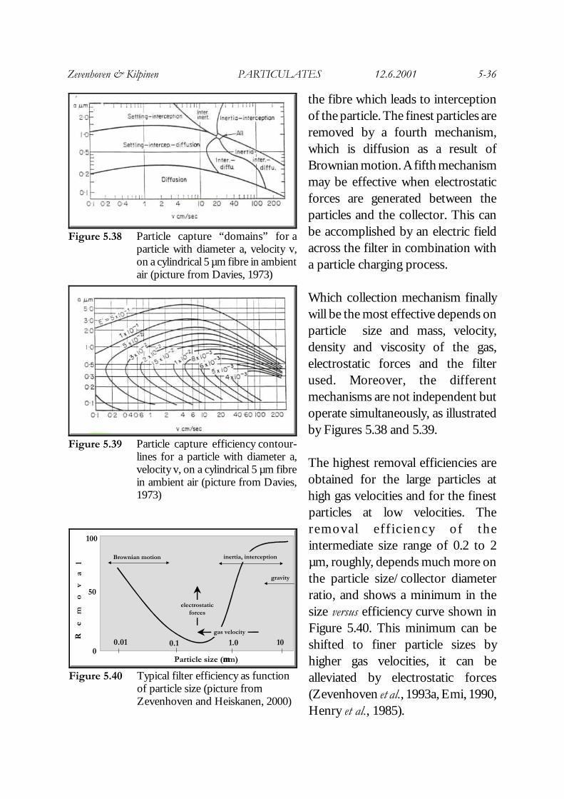
Figure 5.38 Particle capture “domains” for aparticle with diameter a, velocity v,on a cylindrical 5 µm fibre in ambientair (picture from Davies, 1973)
Figure 5.39 Particle capture efficiency contour-lines for a particle with diameter a,velocity v, on a cylindrical 5 µm fibrein ambient air (picture from Davies,1973)
Particle size (µµm)
1.00.10.01 10
Re
mo
va
l
ef
fi
ci
en
cy
(
%)
100
50
0
Brownian motion inertia, interception
electrostaticforces
gas velocity
gravity
Figure 5.40 Typical filter efficiency as functionof particle size (picture fromZevenhoven and Heiskanen, 2000)
the fibre which leads to interceptionof the particle. The finest particles areremoved by a fourth mechanism,which is diffusion as a result ofBrownian motion. A fifth mechanismmay be effective when electrostaticforces are generated between theparticles and the collector. This canbe accomplished by an electric fieldacross the filter in combination witha particle charging process.
Which collection mechanism finallywill be the most effective depends onparticle size and mass, velocity,density and viscosity of the gas,electrostatic forces and the filterused. Moreover, the differentmechanisms are not independent butoperate simultaneously, as illustratedby Figures 5.38 and 5.39.
The highest removal efficiencies areobtained for the large particles athigh gas velocities and for the finestparticles at low velocities. Theremoval eff ic iency of theintermediate size range of 0.2 to 2µm, roughly, depends much more onthe particle size/collector diameterratio, and shows a minimum in thesize versus efficiency curve shown inFigure 5.40. This minimum can beshifted to finer particle sizes byhigher gas velocities, it can bealleviated by electrostatic forces(Zevenhoven et al., 1993a, Emi, 1990,Henry et al., 1985).
Zevenhoven & Kilpinen PARTICULATES 12.6.2001 5-37
A filter for gas or liquid processing can be operated with constant pressure (drop),constant velocity or an intermediate of theses two. Two filtration parameters, beingmedium resistance and specific cake resistance, relate the flow through the filter andpressure drop to time. Assuming that the filter cake is incompressible, Darcy=s Law forflow through a packing with thickness L can be used to relate pressure drop, ∆p (Pa) to fluid flow per unit area, i.e. velocity u (m/s), with fluid viscosity ηfluid (Pa.s):
(5-18)
For a filter cake with porosity ε (-), specific cake resistance, α (m/kg) can be defined:
(5-19)
When the deposited cake has a mass w (kg/m5) per unit filter surface, Ruth=s equationgives (for filtration along x-axis), with medium resistance R (1/m):
(5-20)
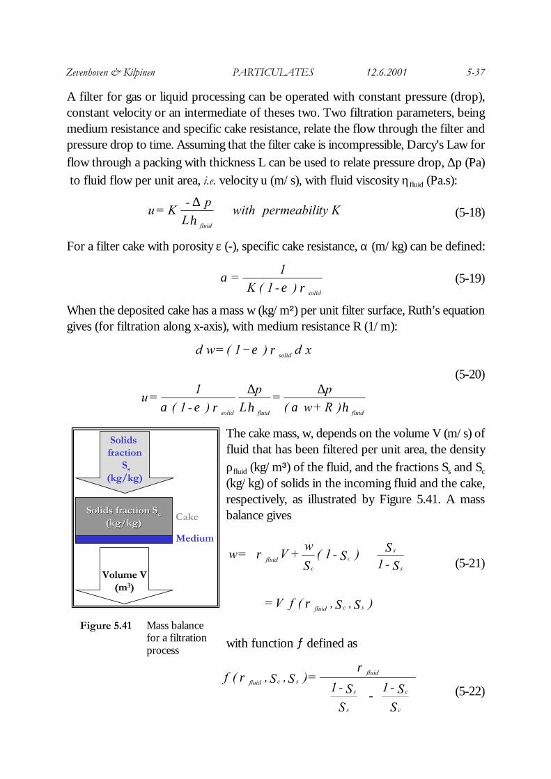
The cake mass, w, depends on the volume V (m/s) offluid that has been filtered per unit area, the densityρfluid (kg/m;) of the fluid, and the fractions Ss and Sc
(kg/kg) of solids in the incoming fluid and the cake,respectively, as illustrated by Figure 5.41. A massbalance gives
(5-21)
with function / defined as
(5-22)
S
S - 1 -
SS - 1
= ) S ,S ,( f
c
c
s
s
fluidscfluid
ρρ
) S ,S ,( f V =
S - 1
S ) S - 1 ( S
w + V = w
scfluid
s
sc
cfluid
ρ
ρ
ηαηρεα
ρε
fluidfluidsolid
solid
) R + w (p
= L
p
) - 1 ( 1
=u
x d ) 1 ( = wd
∆∆
−
Kty permeabili with L
p - K =u
fluidη∆
ρεα
solid ) - 1 ( K 1
=
Solids fraction Solids fraction SScc
(kg/kg)(kg/kg)
Solids fraction
Ss
(kg/kg)
Volume VVolume V(m(m33))
Cake
Medium
Figure 5.41 Mass balancefor a filtrationprocess
Zevenhoven & Kilpinen PARTICULATES 12.6.2001 5-38
For a filtration process that operates under constant pressure (drop), ∆p, the relationbetween time, t, and filtrate volume per unit area V (m/s) is then
(5-23)
Plotting experimental data as t/V versus V produces in this case a line that gives thevalue for the specific cake resistance, α, from the slope, and the medium resistance,R, from the intercept.
Following similar lines for a filtration process that operates under constant flow, V,the relation between time, t, and pressure drop) is then
(5-24)
Plotting for this case experimental data as ∆p versus t produces in this case a line thatgives, again, the value for the specific cake resistance, α, from the slope, and themedium resistance, R, from the intercept.
In practice, the filter cake may show some compressibility. In general this can berelated to the (average) pressure, ∆p, that is exerted on the cake, as
(5-25)More detail about filtration theory can be found in (e.g.) Ives (1975), Coulson andRichardson (1978).
As with ESP systems the operation of a filter may also be improved by gasconditioning. The composition of the ash has a large effect on its cohesivity, thestructure of the filter cake that is formed and whether the ash particles will penetratethe filter medium. This affects the pressure drop but also how well the cake can beremoved from the medium during cleaning, i.e. the residual pressure drop aftercleaning. Conditioning with SO3/NH3 improves the quality of the filter cake (Z section5.7.8).
Typically pressure drops of the order of 1000-1500 Pa are considered reasonable.Besides the dust load to the filter, particle size distribution is an important factor forhow fast the pressure drop increases with time. Especially fine particles can result inrapidly increasing pressure drop and a risk for filter blinding. Usually a somewhatwider particle size distribution is beneficial for filtration operation and performance.
t = V p
R + V
p 2
f
t dV d
=u fluid2fluid
∆∆→
ηαη
) Ru + t u f ( = p constant = t dV d
=u fluid
2αη∆→
p + = : or p = ββ ααααα 100
Zevenhoven & Kilpinen PARTICULATES 12.6.2001 5-39
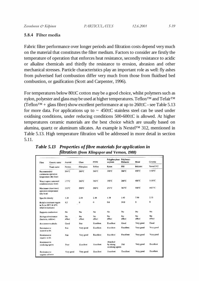
Table 5.13 Properties of fibre materials for application infiltration (from Klingspor and Vernon, 1988)
5.8.4 Filter media
Fabric filter performance over longer periods and filtration costs depend very muchon the material that constitutes the filter medium. Factors to consider are firstly thetemperature of operation that enforces heat resistance, secondly resistance to acidicor alkaline chemicals and thirdly the resistance to erosion, abrasion and othermechanical stresses. Particle characteristics play an important role as well: fly ashesfrom pulverised fuel combustion differ very much from those from fluidised bedcombustion, or gasification (Scott and Carpenter, 1996).
For temperatures below 80EC cotton may be a good choice, whilst polymers such asnylon, polyester and glass may be used at higher temperatures. Teflon™ and Tefair™(Teflon™ + glass fibre) show excellent performance at up to 260EC - see Table 5.13for more data. For applications up to ~ 450EC stainless steel can be used underoxidising conditions, under reducing conditions 500-600EC is allowed. At highertemperatures ceramic materials are the best choice which are usually based onalumina, quartz or aluminum silicates. An example is Nextel™ 312, mentioned inTable 5.13. High temperature filtration will be addressed in more detail in section5.11.
Zevenhoven & Kilpinen PARTICULATES 12.6.2001 5-40
5.8.5 Granular bed filters
A third type of filter besides fabric or rigid barrier filters are granular bed filters.Layers or deep beds of solid granules have been used for a long time for the filtrationof gases and, more importantly, liquids. An example is the filtration of drinking waterby large beds of sand. The principle of filtration is different from what was presentedabove: for granules with a size larger than ~ 1 mm the fine particles will not beretained on the surface of the bed but will penetrate the packed bed structure. Thisis referred to as deep bed filtration (Ives, 1975).
When using cheap bulk solids such as sand, silicate or alumina gravel, temperaturesup to, say, 450-500EC give good gas filtration performance. At higher temperaturesproblems arise due to sintering of the fine particles on surface of the granules whichmay lead to filter blinding at short distances from where the dusty gas enters.
The efficiency of a granular bed filter (GBF) depends on the size distribution andshape of the particles to be filtered and the particle/granule adhesion force. Forstagnant beds typical efficiencies are ~ 99%, for moving bed filters ~ 95%, forfluidised bed GBF systems typical efficiencies are ~ 80%. The friction betweengranules in moving GBFs and the particle collisions in fluidised GBF systemsexplains the lower efficiency compared to a fixed bed GBF.
Granular bed filters are very well suitable for high temperature gas filtration - seesection 5.11.
5.9 Wet scrubbers
Before wet scrubbers were first applied to flue gas desulphurisation (FGD, 7 chapter3) in the mid-1970s they were already in use for particulate emissions control. Figure5.42 shows some possible configurations for wet particulate removal from gasstreams. Although not as powerful as filters and ESPs when it comes to removalefficiency for sub-micron particles, wet scrubbers are able to effectively remove fineparticles and also certain gaseous components from a gas stream by selecting a properwashing liquid. By far the most common is the venturi scrubber (see also Figure 3.9).
Zevenhoven & Kilpinen PARTICULATES 12.6.2001 5-41
Figure 5.42 Wet particulate collectors (pictures from Flagan and Seinfeld, 1988)
Table 5.14 Typical operating conditions for wet particulate scrubbers(from Klingspor and Vernon, 1988)
The capital costs of a wet scrubber are lower than for a baghouse filter or ESP.Operation and maintenance costs, however, are much higher due to high pressuredrops and problems related to corrosion, abrasion, solids build-up, failure of rotatingparts and re-start problems after a shut-down. Despite the advantage of high inlet gasvelocities of ~ 100 m/s, a collection efficiency of ~ 99% overall is obtained withsystem pressure drops of the order of 1 bar. The latter is less problematic when usedin high pressure processes such as PFBC-CC or IGCC (7 chapter 2).

Zevenhoven & Kilpinen PARTICULATES 12.6.2001 5-42
For conventional power plants as much as 3% of the net output may be needed tooperate the wet scrubber, which is also due to the re-heat of the outlet gas to stackconditions.
The major drawback of wet particulate scrubbers is that a gas cleaning problem istransformed in a water treatment problem. Table 5.14 lists the features of differentwet particulate scrubbers - see also Flagan and Seinfeld, § 7.6 (1988).
5.10 Cost comparison ESP, filter, cyclone
A cost comparison for particulate emission control equipment at 10 MWthermal coal-fired boilers in the UK (made in the early 1980s) is given in Table 5.15.
Table 5.15 Cost comparison for particulate control equipment at 10 MWthermal
(data from Klingspor and Vernon, 1988) *
Efficiency %
Capital costUS$ 1982
Operation costUS$/ton removed
High efficiency cyclone 87 10500 1.68
ESP 98.3 96500 2.84
Reverse air baghouse 99.9 49000 3.14
* Assumptions: coal ash, electricity costs 0.0614 US$/kWh, 8000 h/year, filter bags lifetime 2 years
Although ESPs have higher capital costs (~ twice) than those for baghouse filters,operation costs for baghouses are ~ 10% higher. The actual costs for dust controldepends also on the costs or benefits of ash disposal or selling.
Zevenhoven & Kilpinen PARTICULATES 12.6.2001 5-43
Figure 5.44 Options for HTHP gasification fuel gas cleaning (picture from Mitchell,1997)
Figure 5.43 Typical HTHP gas cleaning system forgasification product gas (picture fromETSU, 1998)
5.11 High temperature, high pressure (HTHP) particulate control
5.11.1 Process description, gas purity requirements
The renewed interest for solid fuel-based power generation after the oil crisis of 1973has resulted in clean coal technologies and related projects worldwide. Processesbased on combined cycle (CC) operation of gas turbines and steam turbines offer ahigh thermal efficiency (7 chapter 2) that is also possible when solid fuels such ascoal or peat are used. Pressurised combustion or gasification of solid fuels may beintegrated with a CC power generation system, but only when a powerful gas clean-up
system is used the hotpressurised gases can be directlysent to a gas turbine orexpansion turbine. A typicalset-up for high temperature,high pressure gas (HTHP)clean-up for a gasificationproduct gas is shown in Figure5.43. Typical conditions are500EC or higher at 15-25 barfor the particulate removal.Sulphur- and nitrogen speciesremoval is discussed inChapters 3 and 4, respectively.
Zevenhoven & Kilpinen PARTICULATES 12.6.2001 5-44
Table 5.16 Gas quality specifications for a gas turbine* (from Mitchell, 1997)
A comparison between conventional cold gas cleaning (below 200EC), partial hot gascleaning (260-540EC) and hot gas cleaning (above 550EC) is given in Figure 5.44.Currently HTHP particulate control conditions are determined by the temperaturefor desulphurisation with regenerable sorbents (7 section 3.14) and the controlprocedure for alkali metals (L chapter 8). Above 600EC most alkali will reside in thegas phase (Mitchell, 1997).
A recent gas turbine specification for maximum concentrations of contaminants isgiven in Table 5.16 for the Siemens Westinghouse VX4-3A gas turbine. Particles areallowed up to 2 ppmw with further specification of the size distribution: less than 7½%-wt should be larger than 2 µm. These values, aiming at preventing erosion andfouling of the turbine blades are more stringent that current emission standards,which are typically in the order of 30 - 50 ppmw in countries where these newtechnologies are being implemented (Scott, 1997).
An entrained bed coal gasifier such as marketed by Shell or Texaco produces ~ 50 %bottom slag, ~ 50% fly ash. Typical fly ash particle distributions can go up to 200 µm,with a typical mass average of 20-50 µm and ~10% smaller than 6 µm (Klein-Teeselink and Alderliesten, 1990). Achieving the standards defined in Table 5.16 maybe accomplished with some of the techniques discussed in this chapter so far. Howsuccessful these methods may be under HTHP conditions is tabelised in Table 5.17.
It is clear that cyclones may remove the largest particles but won’t be able to matchthe turbine standards. Also the application of ESPs is questionable at temperaturesabove 450EC. Most suitable appear to be the ceramic rigid barrier filters, although thealternative methods are still under development as well. They will be discussed belowin this order.
Zevenhoven & Kilpinen PARTICULATES 12.6.2001 5-45
Figure 5.46 Filter candles for HTHPparticulate control (picturefrom LeCostanouec, 1999)
Table 5.17 Techniques for hot gas particulate control and their status (from Mitchell, 1997)
Figure 5.45 Siemens Westinghouse filtersystem of Southern Company int h e U S ( p i c t u r e f r o mLeCostanouec, 1999)
5.11.2 Ceramic rigid barrier filters
Ceramic barrier filters can be divided in three types: 1) candle filters, 2) tube filtersand 3) cross/parallel flow filters. A further division can be made of a fibrous orgranular material. The ceramics that are used for fibrous filter media are usuallyalumina or aluminosilicate fibres with a silicon-based binder, the granular filter media
are usually silicon carbide (SiC), aluminaor aluminosilicates. (Mitchell, 1997,ETSU, 1996).
Candle filters are cylindrical tubesclosed at one end with a typical lengthand diameter of 1~1.5 m and 5~10 cm,respectively. They are typically operated“outside-in” (see Figure 5.33) at facevelocities of 1~ 4 cm/s although the
Zevenhoven & Kilpinen PARTICULATES 12.6.2001 5-46
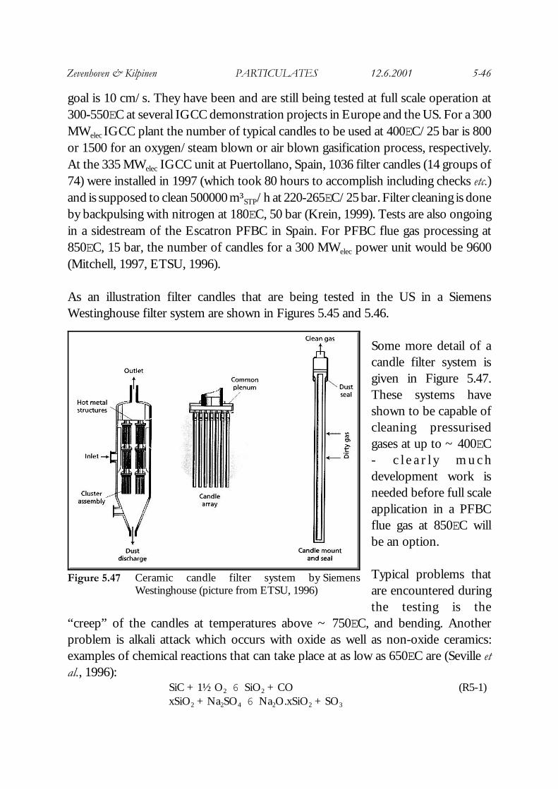
Figure 5.47 Ceramic candle filter system by SiemensWestinghouse (picture from ETSU, 1996)
goal is 10 cm/s. They have been and are still being tested at full scale operation at300-550EC at several IGCC demonstration projects in Europe and the US. For a 300MWelec IGCC plant the number of typical candles to be used at 400EC/25 bar is 800or 1500 for an oxygen/steam blown or air blown gasification process, respectively.At the 335 MWelec IGCC unit at Puertollano, Spain, 1036 filter candles (14 groups of74) were installed in 1997 (which took 80 hours to accomplish including checks etc.)and is supposed to clean 500000 m³STP/h at 220-265EC/25 bar. Filter cleaning is doneby backpulsing with nitrogen at 180EC, 50 bar (Krein, 1999). Tests are also ongoingin a sidestream of the Escatron PFBC in Spain. For PFBC flue gas processing at850EC, 15 bar, the number of candles for a 300 MWelec power unit would be 9600(Mitchell, 1997, ETSU, 1996).
As an illustration filter candles that are being tested in the US in a SiemensWestinghouse filter system are shown in Figures 5.45 and 5.46.
Some more detail of acandle filter system isgiven in Figure 5.47.These systems haveshown to be capable ofcleaning pressurisedgases at up to ~ 400EC- c l e a r l y m u c hdevelopment work isneeded before full scaleapplication in a PFBCflue gas at 850EC willbe an option.
Typical problems thatare encountered duringthe testing is the
“creep” of the candles at temperatures above ~ 750EC, and bending. Anotherproblem is alkali attack which occurs with oxide as well as non-oxide ceramics:examples of chemical reactions that can take place at as low as 650EC are (Seville etal., 1996):
SiC + 1½ O2 6 SiO2 + CO (R5-1)xSiO2 + Na2SO4 6 Na2O.xSiO2 + SO3

Zevenhoven & Kilpinen PARTICULATES 12.6.2001 5-47
Figure 5.49 Ceramic cross-flow filter of SiemensWestinghouse (picture from ETSU, 1996)
Figure 5.48 Tube filter by AsahiGlass Co., Japan(picture from ETSU,1996)
Table 5.18 Short-term and long-term degradation of ceramic HTHP filters(taken from Mitchell, 1997)
or11Al6Si2O13 + 26NaOH 622NaAlSiO4 + 4 NaAl11O17 + 13 H2O (R5-2)
Ceramic tube filters are operated inside-out: theclean gas enters on one end, after reverse pulsingthe dust leaves via the other end. An impression ofa tube filter system as is being used at up to 900EC
at the Wakamatsu PFBC in Japan is shown in Figure 5.48.
The third type of filter is a compact structure of thin ceramic plates that can becleaned by a reverse pulse of clean gas - see Figure 5.49. They offer a ~ 5 times largerfiltration area per unit volume than a candle filter. Problems related to cleaning anddegradation of the laminar structure need to be tackled before large scale use in e.g.
Zevenhoven & Kilpinen PARTICULATES 12.6.2001 5-48
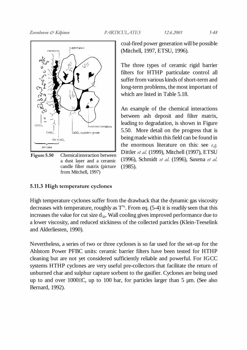
Figure 5.50 Chemical interaction betweena dust layer and a ceramiccandle filter matrix (picturefrom Mitchell, 1997)
coal-fired power generation will be possible(Mitchell, 1997, ETSU, 1996).
The three types of ceramic rigid barrierfilters for HTHP particulate control allsuffer from various kinds of short-term andlong-term problems, the most important ofwhich are listed in Table 5.18.
An example of the chemical interactionsbetween ash deposit and filter matrix,leading to degradation, is shown in Figure5.50. More detail on the progress that isbeing made within this field can be found inthe enormous literature on this: see e.g.Dittler et al. (1999), Mitchell (1997), ETSU(1996), Schmidt et al. (1996), Saxena et al.(1985).
5.11.3 High temperature cyclones
High temperature cyclones suffer from the drawback that the dynamic gas viscositydecreases with temperature, roughly as Tb. From eq. (5-4) it is readily seen that thisincreases the value for cut size d50. Wall cooling gives improved performance due toa lower viscosity, and reduced stickiness of the collected particles (Klein-Teeselinkand Alderliesten, 1990).
Nevertheless, a series of two or three cyclones is so far used for the set-up for theAhlstom Power PFBC units: ceramic barrier filters have been tested for HTHPcleaning but are not yet considered sufficiently reliable and powerful. For IGCCsystems HTHP cyclones are very useful pre-collectors that facilitate the return ofunburned char and sulphur capture sorbent to the gasifier. Cyclones are being usedup to and over 1000EC, up to 100 bar, for particles larger than 5 µm. (See alsoBernard, 1992).

Zevenhoven & Kilpinen PARTICULATES 12.6.2001 5-49
Figure 5.51 Stable corona onset (solid line) and sparkovervoltages (striped line) in ESP at HTHP (picture fromWeber, 1984)
Figure 5.52 New concepts for advanced ESP (picture fromZevenhoven, 1992)
5.11.4 High temperature ESPs
Typically, ESPs areused at 1 bar, 120-450EC, giving overallefficiencies of ~ 99.5% . A t h i g h e rtemperatures the rangeof operating with astable electric fieldbecomes more narrow,since the voltageneeded for coronageneration approachesthe voltage wheresparkover occurs ,e s p e c i a l l y w h e noperating at negativepotential (electrons arefaster than positiveions).
This is illustrated bydata from Weber(1984) in Figure 5.51.Increasing the pressureas well widens theoperation range forvoltage: comparing theresults from 1 bar,
100EC and 21 bar, 1000EC shows roughly the same voltages for corona onset and forsparkover. For PFBC flue gas at 400-700EC, 5-15 bar the use of ESP has beenthought of as an option, supported by good ash properties as well. Since the early1990s very little progress has been reported on this area, though. Other systems forhigh temperature are based on separate optimisation of the particle charging processand the particle removal process - see Figure 5.52. A serious disadvantage are theconsiderable heat losses when operating these rather large devices at elevatedtemperatures.
Zevenhoven & Kilpinen PARTICULATES 12.6.2001 5-50
5.11.5 High temperature fabric filters
Fabric filters based on textile or polymer fibres are commonly used up to ~ 300EC.A process where a baghouse filter is applied at high temperature is the Babcock andWilcox (B&W) SOx-NOx-ROx-BOx (SNRB™) process. In this process a baghousewhich is operated at 440-480EC, removes fly ash and SO2, which reacts with dry-injected limestone, (7 chapter 3) and NO by reaction with NH3 (7 chapter 4) whichis injected upstream of the filter as well. The SCR catalyst is located inside thefilterbags (US DOE, 1999).
Filter bags made of 3M’s Nextel™ material (see Table 5.13), based on boronsilicateshould allow for continuous operation at 1170EC, with a maximum of 1340EC(ETSU, 1996). Tests at ~ 550EC under oxidising and reducing conditions showedremoval efficiencies of ~ 99% at face velocities ~ 1 cm/s.
5.11.6 High temperature metallic filters
Stainless steel suffers from severe corrision under oxidising conditions at above ~450EC, under reducing conditions it may be used up to 600EC. In gasificationproduct gas the corrosion is directly related to the chromium (Cr) and nickel (Ni)content, with nickel producing Ni3S2 with the sulphur in the gas (H2S). Preferablymetallic filters are used in gasification product gas below 400EC, H2S below 300 ppm,and no chlorine in the gas (L chapter 7). New sintered alloys such as Fe3Al, with 2or 5% Cr are currently being tested for IGCC and PFBC projects in the US.
5.11.7 High temperature granular bed filters
Granular bed filters (GBFs) for hot gas cleaning are basically a stagnant or movingbed of coarse (~ 3 mm) granular solids, made of basically the same materials asceramic candle and tube filters are made of. In principle the granules are chemicallyinert, although it has been considered to remove particulates and alkali from PFBCflue gases simultaneously using a GBF or apply ammonia dehydrogenation catalysts(Zakkay et al., 1989, McDaniel et al., 1995). Filter velocities can be relatively high, ofthe order 0.1 - 1 m/s. Some pro’s and contra’s of GBFs for hot gas cleaningapplication are given in Table 5.19.
Fixed bed GBFs offer high efficiencies under HTHP conditions but need a cleaning/regeneration stage, whilst moving bed GBF systems may remove only 90-95% of the
Zevenhoven & Kilpinen PARTICULATES 12.6.2001 5-51
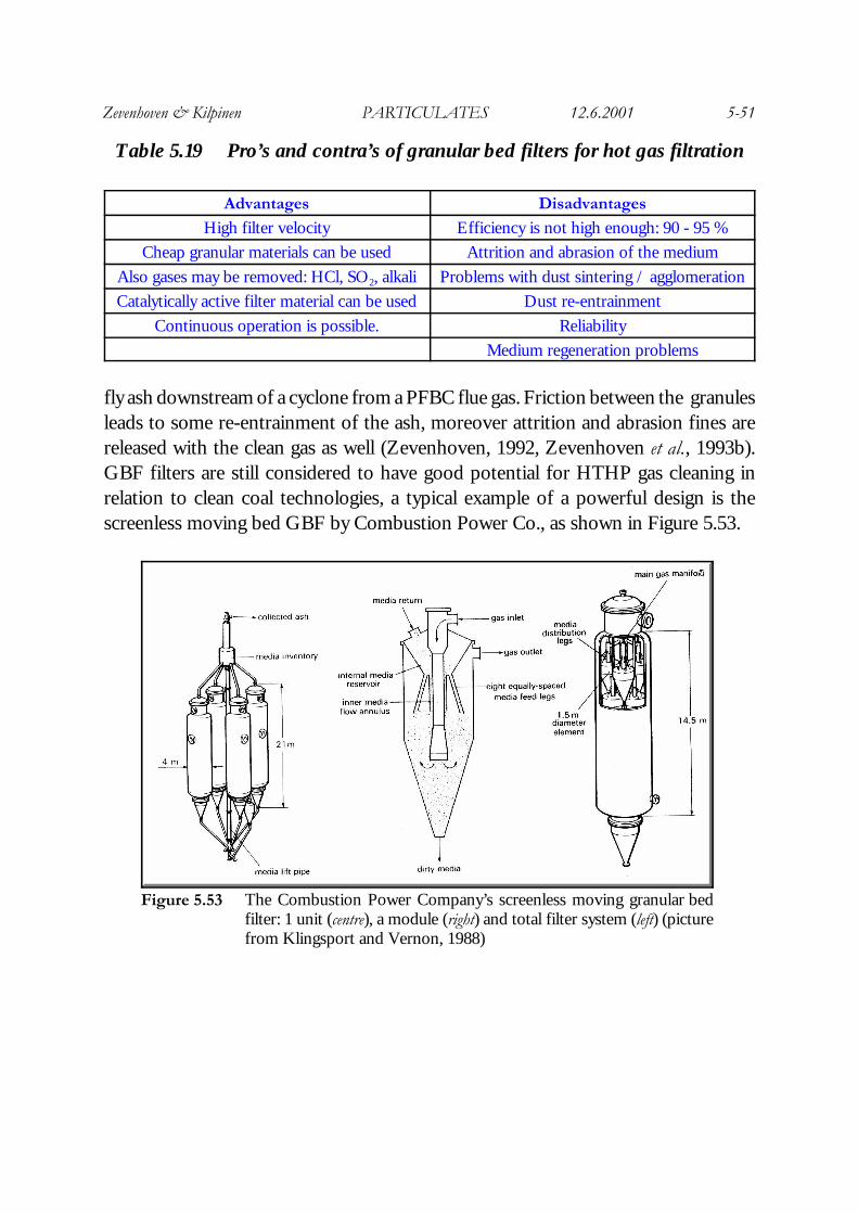
Figure 5.53 The Combustion Power Company’s screenless moving granular bedfilter: 1 unit (centre), a module (right) and total filter system (left) (picturefrom Klingsport and Vernon, 1988)
Table 5.19 Pro’s and contra’s of granular bed filters for hot gas filtration
Advantages Disadvantages
High filter velocity Efficiency is not high enough: 90 - 95 %
Cheap granular materials can be used Attrition and abrasion of the medium
Also gases may be removed: HCl, SO2, alkali Problems with dust sintering / agglomeration
Catalytically active filter material can be used Dust re-entrainment
Continuous operation is possible. Reliability
Medium regeneration problems
fly ash downstream of a cyclone from a PFBC flue gas. Friction between the granulesleads to some re-entrainment of the ash, moreover attrition and abrasion fines arereleased with the clean gas as well (Zevenhoven, 1992, Zevenhoven et al., 1993b).GBF filters are still considered to have good potential for HTHP gas cleaning inrelation to clean coal technologies, a typical example of a powerful design is thescreenless moving bed GBF by Combustion Power Co., as shown in Figure 5.53.
Zevenhoven & Kilpinen PARTICULATES 12.6.2001 5-52
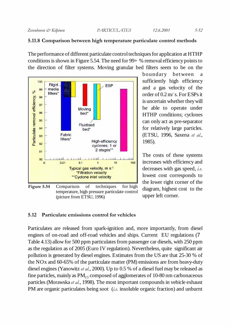
Figure 5.54 Comparison of techniques for hightemperature, high pressure particulate control(picture from ETSU, 1996)
5.11.8 Comparison between high temperature particulate control methods
The performance of different particulate control techniques for application at HTHPconditions is shown in Figure 5.54. The need for 99+ % removal efficiency points tothe direction of filter systems. Moving granular bed filters seem to be on the
boundary between asufficiently high efficiencyand a gas velocity of theorder of 0.2 m/s. For ESPs itis uncertain whether they willbe able to operate underHTHP conditions; cyclonescan only act as pre-separatorfor relatively large particles.(ETSU, 1996, Saxena et al.,1985).
The costs of these systemsincreases with efficiency anddecreases with gas speed, i.e.lowest cost corresponds tothe lower right corner of thediagram, highest cost to theupper left corner.
5.12 Particulate emissions control for vehicles
Particulates are released from spark-ignition and, more importantly, from dieselengines of on-road and off-road vehicles and ships. Current EU regulations (7Table 4.13) allow for 500 ppm particulates from passenger car diesels, with 250 ppmas the regulation as of 2005 (Euro IV regulation). Nevertheless, quite significant airpollution is generated by diesel engines. Estimates from the US are that 25-30 % ofthe NOx and 60-65% of the particulate matter (PM) emissions are from heavy-dutydiesel engines (Yanowitz et al., 2000). Up to 0.5 % of a diesel fuel may be released asfine particles, mainly as PM2.5 composed of agglomerates of 10-80 nm carbonaceousparticles (Morawska et al., 1998). The most important compounds in vehicle exhaustPM are organic particulates being soot (i.e. insoluble organic fraction) and unburnt
Zevenhoven & Kilpinen PARTICULATES 12.6.2001 5-53
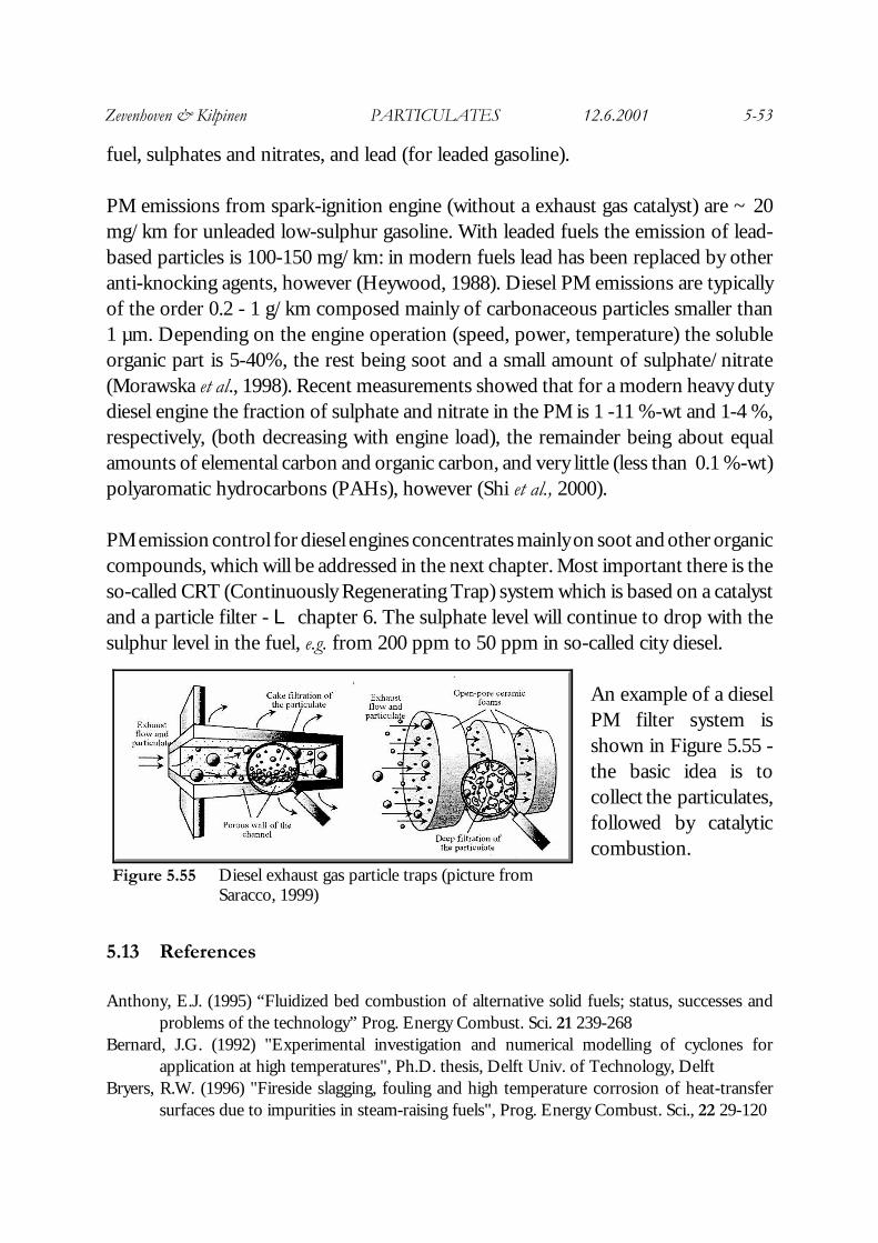
Figure 5.55 Diesel exhaust gas particle traps (picture fromSaracco, 1999)
fuel, sulphates and nitrates, and lead (for leaded gasoline).
PM emissions from spark-ignition engine (without a exhaust gas catalyst) are ~ 20mg/km for unleaded low-sulphur gasoline. With leaded fuels the emission of lead-based particles is 100-150 mg/km: in modern fuels lead has been replaced by otheranti-knocking agents, however (Heywood, 1988). Diesel PM emissions are typicallyof the order 0.2 - 1 g/km composed mainly of carbonaceous particles smaller than1 µm. Depending on the engine operation (speed, power, temperature) the solubleorganic part is 5-40%, the rest being soot and a small amount of sulphate/nitrate(Morawska et al., 1998). Recent measurements showed that for a modern heavy dutydiesel engine the fraction of sulphate and nitrate in the PM is 1 -11 %-wt and 1-4 %,respectively, (both decreasing with engine load), the remainder being about equalamounts of elemental carbon and organic carbon, and very little (less than 0.1 %-wt)polyaromatic hydrocarbons (PAHs), however (Shi et al., 2000).
PM emission control for diesel engines concentrates mainly on soot and other organiccompounds, which will be addressed in the next chapter. Most important there is theso-called CRT (Continuously Regenerating Trap) system which is based on a catalystand a particle filter - L chapter 6. The sulphate level will continue to drop with thesulphur level in the fuel, e.g. from 200 ppm to 50 ppm in so-called city diesel.
An example of a dieselPM filter system isshown in Figure 5.55 -the basic idea is tocollect the particulates,followed by catalyticcombustion.
5.13 References
Anthony, E.J. (1995) “Fluidized bed combustion of alternative solid fuels; status, successes andproblems of the technology” Prog. Energy Combust. Sci. 21 239-268
Bernard, J.G. (1992) "Experimental investigation and numerical modelling of cyclones forapplication at high temperatures", Ph.D. thesis, Delft Univ. of Technology, Delft
Bryers, R.W. (1996) "Fireside slagging, fouling and high temperature corrosion of heat-transfersurfaces due to impurities in steam-raising fuels", Prog. Energy Combust. Sci., 22 29-120
Zevenhoven & Kilpinen PARTICULATES 12.6.2001 5-54
Böhm, J. (1982) "Electrostatic precipitators", Elsevier, AmsterdamCabanillas, A., Armesto, L, Bahillo, A., Otero, J. (1999) “Fluidised bed combustion of different
wastes: summary of experiences”, Proc. of the 39th IEA FBC meeting, Madrid (Spain), Nov.22-24, 1999
Carpenter, A.M. (1998) “Switching to cheaper coals for power generation”, IEA Coal Research,report CCC/01, London
CIEMAT (1998?) “Flue gas cleaning” European Commission DG XVII Clean Coal TechnologyHandbook, Section 5, Madrid/Brussels
Cooper, C.D., Alley, F.C. (1994) "Air pollution control", 2nd Ed. Waveland Press, Illinois Chapters3,4,5,6 & 7
Coulson, J.M., Richardson, J.F., Backhurst, J.R., Harker, J.H. (1978) "Chemical Engineering -Volume 2", 3rd Ed., Pergamon Press, Oxford Chapter 8
Davies, C.N. (1973) "Air filtration", Academic Press, LondonDIN (1978) “Determination of the ash content” (in German) Deutsches Institut für Normung e.V.
Berlin, #15719, Beuth Verlag, BerlinDittler, A., Hemmler, G. Kasper, G. (Eds.) (1999) “High temperature gas cleaning”, Vol. II, 1999,
University of Karlsruhe (Germany)Emi, H. (1990) “Fundamentals of aerosol filtration”, KONA 8 83-91ETSU (1996) “Hot gas particulate clean-up”, Technology status report TSR001, ETSU, Harwell
(UK)ETSU (1998) “Integrated hot fuel-gas cleaning for advanced gasificationcombined cycle processes”
Project summary 166, Febr. 1998, ESTU, Harwell (UK)Flagan, R.C, Seinfeld, J.H. (1988) "Fundamentals of air pollution control engineering", Prentice-Hill,
New Jersey, Chapter 7Henry, R.F., Podolski, W.F., Saxena, S.C. (1985) “A review of electrostatically augmented gas
cleaning devices for particulate removal” IEEE Trans. Ind. Appl. IA-21(4) 939-948Heywood, J.B. (1988) “Internal combustion engine fundamentals” McGraw-Hill, New YorkHinds, W.C. (1982) “Aerosol technology” Wiley & Sons, New YorkIinoya, K., Gotoh, K., Higashitani, L. (1991) “Powder technology handbook”, Marcel Dekker, New
YorkIves, K.J. (Ed.) (1975) “The scientific basis of filtration”, Nato advanced study institute series, Series
E: Applied Sciences. No 2, Noordhoof, Leiden, The NetherlandsKamimoto, T., Kobayashi, H. (1991) “Combustion processes in diesel engines” Progr. Energy
Combust. Sci. 17 163-189Klein-Teeselink, H., Alderliesten, P.T. (1990) "Systeemstudie hoge-temperatuur gasreiniging,
deelstudie 2.4 Stofverwijdering", ECN Report ECN-C--90-052Klingspor, J.S., Vernon, J.L. (1988) "Particulate control for coal combustion", IEA Coal Research,
report IEACR/03, LondonKrein, J. (1999) “LLB candle filter for the ELCOGAS IGCC power plant Puertollano/Spain”,
in: “High temperature gas cleaning”, Vol. II, 1999, A. Dittler, G. Hemmler, G. Kasper(Eds.), University of Karlsruhe, Germany, pp. 253-260
Kuffel, E., Zaengl, W.S. (1984) “High voltage engineering”, Pergamon Press, Oxford (UK)Kunii, D., Levenspiel, O. (1991) “Fluidization engineering”, 2nd Ed. Butterworth-Heinemann,
Boston (MA)LeCostanouec, J.-F. (1999) “3D braided reinforced ceramic hot gas filters”, in: “High temperature
Zevenhoven & Kilpinen PARTICULATES 12.6.2001 5-55
gas cleaning”, Vol. II, 1999, A. Dittler, G. Hemmler, G. Kasper (Eds.), University ofKarlsruhe, Germany, pp. 428-441
McConville, A. (1997) “Emission standards handbook 1996: air pollutant standards for coal-firedplants” IEA Coal Research, report IEACR/96, London
McDaniel, H.M., Haas, J.C., Wilson, K.B., Gupta, R.P. (1995) “Moving granular-bed filter for multi-contaminant control” Proc. of the 12th Ann. Int. Pittsburgh Coal Conf., Sept. 1995, S.-H.Chiang (Ed.) Pittsburgh (PA) pp. 237-242
Mitchell, S.C. (1997) "Hot gas particulate filtration", IEA Coal Research, report IEACR/95, LondonMorawska, L., Bofinger, N.D., Kocis, L., Mwankwoala, Al. (1998) “Submicrometer and
supermicrometer particles from diesel vehicle emissions” Environm. Sci. Technol. 32(14)2033-2042
Pauthenier, M.M., Moreau-Hanot, M. (1932) “La charge des particules sphériques dans un championisé”, Journal de Physique 12 590-613
Saracco, G. (1999) “Coupling catalysis and high temperature resistant filters”, in: “High temperaturegas cleaning”, Vol. II, 1999, A. Dittler, G. Hemmler, G. Kasper (Eds.), University ofKarlsruhe, Germany, pp. 627-640
Sarofim, A.F., Helble, J.J. (1993) “The structure of combustion-generated aerosol particles”, Proc.of the 5th Finnish National Aerosol Symp., P. Mikkanen, K. Hämeri, E. Kauppinen (Eds.),Baltic Sea, June 1993, pp. 59-63
Saxena, S.C., Henry, R.F., Podolski, W.F. (1985) “Particulate removal from high temperature highpressure combustion gases” Progr. Energy Combust. Sci. 11 193-252
Schmidt, E., Gäng, P., Pliz, T., Dittler, A. (Eds.) (1996) “High temperature gas cleaning”, Universityof Karlsruhe (Germany)
Scott, D.H. (1997) “Improving existing power stations to comply with emerging emissionsstandards” IEA Coal Research, report IEACR/92, London
Scott, D.H., Carpenter, A.M. (1997) “Advanced power systems and coal quality”, IEA CoalResearch, report IEACR/87, London
Seville, J.P.K., Ivatt, S., Burnard, G.K. (1996) “Recent advances in particulate removal from hotprocess gases” in: “High temperature gas cleaning”, 1996, E. Schmidt, P. Gäng, T. Pliz, A.Dittler (Eds.), University of Karlsruhe, Germany, pp. 3-25
Shi, J.P., Mark, D., Harrison, R.M. (2000) “Characterisation of particles from a current technologyheavy-duty diesel engine” Environm. Sci. Technol. 34(5) 748-755
Sloss, L.L., Smith, I.M., Adams, D.M.B. (1996) "Pulverised coal ash- requirements for utilisation",IEA Coal Research, report IEACR/88, London
Sloss, L.L., Smith, I.M. (1998) “ PM10/PM2.5 - emissions and effects” IEA Coal Research, reportCCC/08, London
Soud, H.N. (1995) "Developments in particulate control for coal combustion", IEA Coal Research,report IEACR/78, London
Soud, H.N., Mitchell, S.C. (1997) "Particulate control handbook for coal-fired plants", IEA CoalResearch, report IEACR/93, London
Stringer, J., Meadowcroft, D.B. (1990) “A review of hot gas cleanup requirements for coal fired gasturbines” Trans. I. Chem. E Part B., Aug. 1990, 68 181-194
US DOE (1999) “Technologies for the combined control of sulphur dioxide and nitrogen oxidesemissions from coal-fired boilers”, Topical Report 13, May 1999
Weber, E. (1984) "Electrostatic precipitation at extreme values for temperature and pressure", Proc.
Zevenhoven & Kilpinen PARTICULATES 12.6.2001 5-56
of the 2nd. Int. Conf. on Electrostatic Precipitators, Kyoto, Japan, 85-95Yang, W., Newby, R., Lippert, T., Keairns, D. (1992) AMGBF concept looks good for hot gas
cleanup@ Modern Power Systems 10 (11) November, 1992, 21-24Yanowitz, J., McCormick, R.L., Grabowski, M.S. (2000) AIn-use emissions from heavy duty-diesel
engines@ Environm. Sci. Technol. 34(5) 729-740Zakkay, V. et al. (1989) AParticulate and alkali capture from PFBC flue gas utilizing granular bed
filter@ Combust. Sci. and Tech. 68 113-130Zevenhoven, C.A.P. (1992) "Particle charging and granular bed filtration for high temperature
application", Ph.D. thesis, Delft Univ. of Technol., DelftZevenhoven, C.A.P., Hein, K.R.G., Scarlett, B. (1993a) AMoving granular bed filtration with
electrostatic enhancement for high-temperature gas clean-up@ Filtration & Separation, 30(6)550-553
Zevenhoven, C.A.P., Andries, J., Hein, K.R.G., Scarlett, B. (1993b) AHigh temperature gas cleaningfor PFBC using a moving granular bed filter@ in: Gas Cleaning at High Temperatures, R.Clift and J.P.K. Seville (Eds.), Blackie Academic & Professional, London
Zevenhoven, R. (1999) "Uni-polar field charging of particles: effects of particle conductivity androtation", J. of Electrostat. 46 1-12
Zevenhoven, R., Heiskanen, K. (2000) AParticle technology for thermal power engineers@, coursematerial ENE-47.200, Sept. 6-8, Helsinki Univ. of Technology, Espoo (Finland)
APPENDIX Calculating the terminal settling velocity of particles
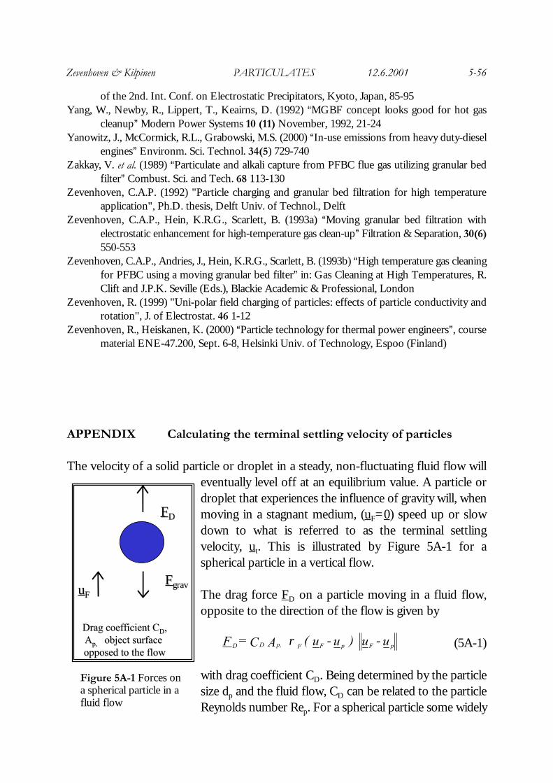
The velocity of a solid particle or droplet in a steady, non-fluctuating fluid flow willeventually level off at an equilibrium value. A particle ordroplet that experiences the influence of gravity will, whenmoving in a stagnant medium, (uF=0) speed up or slowdown to what is referred to as the terminal settlingvelocity, ut. This is illustrated by Figure 5A-1 for aspherical particle in a vertical flow.
The drag force FD on a particle moving in a fluid flow,opposite to the direction of the flow is given by
(5A-1)
with drag coefficient CD. Being determined by the particlesize dp and the fluid flow, CD can be related to the particleReynolds number Rep. For a spherical particle some widely
FFDD
uuFFFFgravgrav
Drag coefficient CDrag coefficient CDD,,AApp,,⊥⊥ object surface object surface opposed to the flowopposed to the flow
Figure 5A-1 Forces ona spherical particle in afluid flow
u - u ) u - u ( A C = F pFpFFp,DD ρ⊥
Zevenhoven & Kilpinen PARTICULATES 12.6.2001 5-57
used expressions are, besides Stokes= Law:
(5A-2)
The terminal settling velocity ut of a spherical particle follows from a force balancein the vertical direction, and equating the acceleration of the particle to zero:
(5A-3)
where mp and Vp are the mass and volume of the particle, respectively, gravity g andfluid and particle densities ρF and ρS.The problem of calculating ut whilst CD is itselfa function of ut can be solved by considering the parameter CDRep,t² (Rep,t is Rep withvelocity u = ut) instead, which is also known as the Archimedes number:
(5A-4)
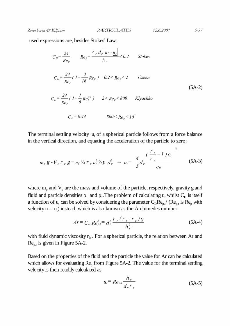
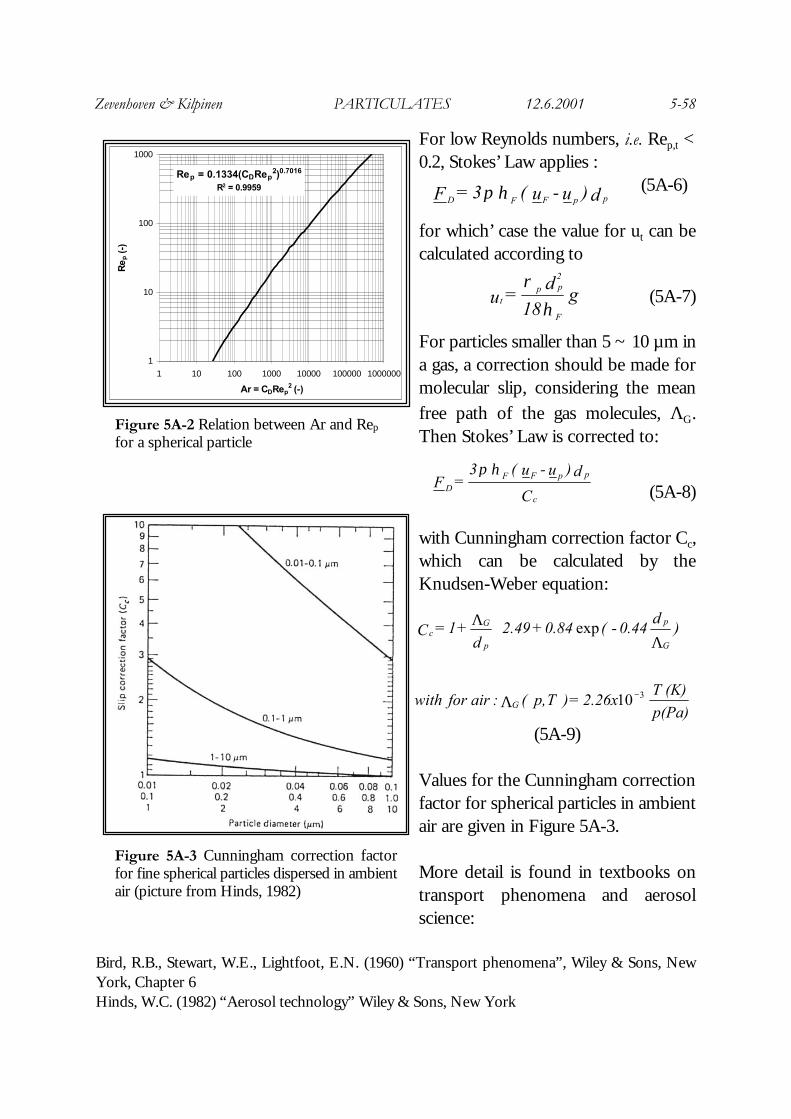
with fluid dynamic viscosity ηF. For a spherical particle, the relation between Ar andRep,t is given in Figure 5A-2.
Based on the properties of the fluid and the particle the value for Ar can be calculatedwhich allows for evaluating Rep from Figure 5A-2. The value for the terminal settlingvelocity is then readily calculated as
(5A-5)
10 < Re < 800 0.44 = C
Klyachko 800 < Re < 2 ) Re 61
+ 1 ( Re
24 = C
Oseen 2 < Re < 0.2 ) Re 16
3 + 1 (
Re
24 = C
okes St0.2 < u - u d
= Re Re
24 = C
5pD
p2/3p
pD
ppp
D
F
pFpF
pp
Dη
ρ
−→
c
g ) 1 ( d
34
= u d ¼ u c = g V g mD
F
S
pt2p
2tFDFpp
ρρ
πρρ
½
½-
ηρρρ
2
F
FSF3p
2t p,D
g ) ( d = Re C = Ar
-
ρη
Fp
Ft p,t
d Re = u
Zevenhoven & Kilpinen PARTICULATES 12.6.2001 5-58
For low Reynolds numbers, i.e. Rep,t <0.2, Stokes’ Law applies :
(5A-6)
for which’ case the value for ut can becalculated according to
(5A-7)
For particles smaller than 5 ~ 10 µm ina gas, a correction should be made formolecular slip, considering the meanfree path of the gas molecules, ΛG.Then Stokes’ Law is corrected to:
(5A-8)
with Cunningham correction factor Cc,which can be calculated by theKnudsen-Weber equation:
(5A-9)
Values for the Cunningham correctionfactor for spherical particles in ambientair are given in Figure 5A-3.
More detail is found in textbooks ontransport phenomena and aerosolscience:
Bird, R.B., Stewart, W.E., Lightfoot, E.N. (1960) “Transport phenomena”, Wiley & Sons, NewYork, Chapter 6Hinds, W.C. (1982) “Aerosol technology” Wiley & Sons, New York
p(Pa)
(K) T 2.26x = ) T p, ( : air for with
)d
0.44 - ( 0.84 + 2.49 d
+ 1 = C
G
G
p
p
Gc
310
exp
−Λ
ΛΛ
1
10
100
1000
1 10 100 1000 10000 100000 1000000
Ar = CDRep2 (-)
Re
p (
-)
Rep = 0.1334(CDRep2)0.7016
R2 = 0.9959
Figure 5A-2 Relation between Ar and Rep
for a spherical particle
d )u - u ( 3 = F ppFFD ηπ
g 18d
= uF
2pp
tη
ρ
C
d )u - u ( 3 = F
c
ppFFD
ηπ
Figure 5A-3 Cunningham correction factorfor fine spherical particles dispersed in ambientair (picture from Hinds, 1982)