Embed Size (px)
Citation preview
Document: 151142-L8 Rev: LECN: 17-0387
Installation and Operation Guide
5895XLIntelligent Power Module
2
Fire Alarm & Emergency Communication System LimitationsWhile a life safety system may lower insurance rates, it is not a substitute for life and property insurance!An automatic fire alarm system—typically made up of smoke detectors, heat detectors, manual pull stations, audible warning devices, and a fire alarm control panel (FACP) with remote noti-fication capability—can provide early warning of a developing fire. Such a system, however, does not assure protection against property damage or loss of life resulting from a fire.An emergency communication system—typically made up of an automatic fire alarm system (as described above) and a life safety communication system that may include an autonomous control unit (ACU), local operating console (LOC), voice com-munication, and other various inter-operable communication methods—can broadcast a mass notification message. Such a system, however, does not assure protection against property damage or loss of life resulting from a fire or life safety event.The Manufacturer recommends that smoke and/or heat detectors be located throughout a protected premises following the recommendations of the current edition of the National Fire Protection Association Standard 72 (NFPA 72), manufacturer's recommendations, State and local codes, and the recommendations contained in the Guide for Proper Use of System Smoke Detectors, which is made available at no charge to all installing dealers. This document can be found at http://www.systemsensor.com/appguides/. A study by the Federal Emergency Management Agency (an agency of the United States government) indicated that smoke detectors may not go off in as many as 35% of all fires. While fire alarm systems are designed to provide early warning against fire, they do not guarantee warning or protection against fire. A fire alarm system may not provide timely or adequate warning, or simply may not function, for a variety of reasons: Smoke detectors may not sense fire where smoke cannot reach the detectors such as in chimneys, in or behind walls, on roofs, or on the other side of closed doors. Smoke detectors also may not sense a fire on another level or floor of a building. A second-floor detector, for example, may not sense a first-floor or basement fire. Particles of combustion or “smoke” from a developing fire may not reach the sensing chambers of smoke detectors because:• Barriers such as closed or partially closed doors, walls,
chimneys, even wet or humid areas may inhibit particle or smoke flow.
• Smoke particles may become “cold,” stratify, and not reach the ceiling or upper walls where detectors are located.
• Smoke particles may be blown away from detectors by air outlets, such as air conditioning vents.
• Smoke particles may be drawn into air returns before reach-ing the detector.
The amount of “smoke” present may be insufficient to alarm smoke detectors. Smoke detectors are designed to alarm at various levels of smoke density. If such density levels are not created by a developing fire at the location of detectors, the detectors will not go into alarm.Smoke detectors, even when working properly, have sensing limitations. Detectors that have photoelectronic sensing cham-bers tend to detect smoldering fires better than flaming fires, which have little visible smoke. Detectors that have ionizing-type sensing chambers tend to detect fast-flaming fires better than smoldering fires. Because fires develop in different ways and are often unpredictable in their growth, neither type of detector is necessarily best and a given type of detector may not provide adequate warning of a fire. Smoke detectors cannot be expected to provide adequate warning of fires caused by arson, children playing with matches (especially in bedrooms), smoking in bed, and violent explo-
sions (caused by escaping gas, improper storage of flammable materials, etc.). Heat detectors do not sense particles of combustion and alarm only when heat on their sensors increases at a predetermined rate or reaches a predetermined level. Rate-of-rise heat detec-tors may be subject to reduced sensitivity over time. For this reason, the rate-of-rise feature of each detector should be tested at least once per year by a qualified fire protection spe-cialist. Heat detectors are designed to protect property, not life. IMPORTANT! Smoke detectors must be installed in the same room as the control panel and in rooms used by the system for the connection of alarm transmission wiring, communications, signaling, and/or power. If detectors are not so located, a devel-oping fire may damage the alarm system, compromising its ability to report a fire. Audible warning devices such as bells, horns, strobes, speakers and displays may not alert people if these devices are located on the other side of closed or partly open doors or are located on another floor of a building. Any warning device may fail to alert people with a disability or those who have recently consumed drugs, alcohol, or medication. Please note that:• An emergency communication system may take priority over
a fire alarm system in the event of a life safety emergency.• Voice messaging systems must be designed to meet intelli-
gibility requirements as defined by NFPA, local codes, and Authorities Having Jurisdiction (AHJ).
• Language and instructional requirements must be clearly disseminated on any local displays.
• Strobes can, under certain circumstances, cause seizures in people with conditions such as epilepsy.
• Studies have shown that certain people, even when they hear a fire alarm signal, do not respond to or comprehend the meaning of the signal. Audible devices, such as horns and bells, can have different tonal patterns and frequencies. It is the property owner's responsibility to conduct fire drills and other training exercises to make people aware of fire alarm signals and instruct them on the proper reaction to alarm signals.
• In rare instances, the sounding of a warning device can cause temporary or permanent hearing loss.
A life safety system will not operate without any electrical power. If AC power fails, the system will operate from standby batteries only for a specified time and only if the batteries have been properly maintained and replaced regularly. Equipment used in the system may not be technically com-patible with the control panel. It is essential to use only equip-ment listed for service with your control panel. Telephone lines needed to transmit alarm signals from a prem-ises to a central monitoring station may be out of service or temporarily disabled. For added protection against telephone line failure, backup radio transmission systems are recom-mended. The most common cause of life safety system malfunction is inadequate maintenance. To keep the entire life safety system in excellent working order, ongoing maintenance is required per the manufacturer's recommendations, and UL and NFPA stan-dards. At a minimum, the requirements of NFPA 72 shall be fol-lowed. Environments with large amounts of dust, dirt, or high air velocity require more frequent maintenance. A maintenance agreement should be arranged through the local manufac-turer's representative. Maintenance should be scheduled monthly or as required by National and/or local fire codes and should be performed by authorized professional life safety sys-tem installers only. Adequate written records of all inspections
3
Installation PrecautionsAdherence to the following will aid in problem-free installation with long-term reliability:WARNING - Several different sources of power can be connected to the fire alarm control panel. Disconnect all sources of power before servicing. Control unit and associated equipment may be damaged by removing and/or inserting cards, modules, or interconnecting cables while the unit is energized. Do not attempt to install, service, or operate this unit until manuals are read and understood.
CAUTION - System Re-acceptance Test after Software Changes: To ensure proper system operation, this product must be tested in accordance with NFPA 72 after any pro-gramming operation or change in site-specific software. Re-acceptance testing is required after any change, addition or deletion of system components, or after any modification, repair or adjustment to system hardware or wiring. All compo-nents, circuits, system operations, or software functions known to be affected by a change must be 100% tested. In addition, to ensure that other operations are not inadvertently affected, at least 10% of initiating devices that are not directly affected by the change, up to a maximum of 50 devices, must also be tested and proper system operation verified.
This system meets NFPA requirements for operation at 0-49º C/32-120º F and at a relative humidity . However, the useful life of the system's standby batteries and the electronic com-ponents may be adversely affected by extreme temperature ranges and humidity. Therefore, it is recommended that this system and its peripherals be installed in an environment with a normal room temperature of 15-27º C/60-80º F.
Verify that wire sizes are adequate for all initiating and indi-cating device loops. Most devices cannot tolerate more than a 10% I.R. drop from the specified device voltage.
Like all solid state electronic devices, this system may operate erratically or can be damaged when subjected to light-ning induced transients. Although no system is completely immune from lightning transients and interference, proper grounding will reduce susceptibility. Overhead or outside aerial wiring is not recommended, due to an increased sus-ceptibility to nearby lightning strikes. Consult with the Techni-cal Services Department if any problems are anticipated or encountered.
Disconnect AC power and batteries prior to removing or inserting circuit boards. Failure to do so can damage circuits.
Remove all electronic assemblies prior to any drilling, filing, reaming, or punching of the enclosure. When possible, make all cable entries from the sides or rear. Before making modifi-cations, verify that they will not interfere with battery, trans-former, or printed circuit board location.
Do not tighten screw terminals more than 9 in-lbs. Over-tightening may damage threads, resulting in reduced terminal contact pressure and difficulty with screw terminal removal.
This system contains static-sensitive components. Always ground yourself with a proper wrist strap before han-dling any circuits so that static charges are removed from the body. Use static suppressive packaging to protect electronic assemblies removed from the unit.
Follow the instructions in the installation, operating, and programming manuals. These instructions must be followed to avoid damage to the control panel and associated equipment. FACP operation and reliability depend upon proper installa-tion.
Precau-D1-9-2005

4
Documentation FeedbackYour feedback helps us keep our documentation up-to-date and accurate. If you have a question or encounter a problem not covered in this manual, contact Silent Knight Technical Support at 800-446-6444.
Please give the following information:
• Product name and version number (if applicable)
• Printed manual
• Topic Title
• Page number (for printed manual)
• Brief description of content you think should be improved or corrected
• Your suggestion for how to correct/improve documentation
To order parts, contact Silent Knight Sales at 800-328-0103.
Content
151142 1
Content
Section 1Overview ...................................................................................................................................................... 2-1
1.1 5895XL Description ..................................................................................................................2-11.1.1 Maximum Number of SBUS Modules ................................................................................2-1
1.2 Agency Requirements ..............................................................................................................2-4
Section 2Before You Begin Installing ............................................................................................... 3-1
2.1 Inventory ...................................................................................................................................3-12.2 Environmental Specifications ...................................................................................................3-12.3 Software Downloads ................................................................................................................3-12.4 5895XL Board and Terminal Strip Description .........................................................................3-22.5 Earth Fault Resistance .............................................................................................................3-42.6 Calculating Current Draw and Standby Battery ........................................................................3-5
2.6.1 Worksheet Requirements ..................................................................................................3-52.6.1.1 Maximum Battery Standby Load ..............................................................................3-5
2.6.2 Current Draw Worksheet ...................................................................................................3-62.6.3 Current Draw Worksheet for SD SLC Devices ..................................................................3-9
2.7 Wiring Specifications ..............................................................................................................3-112.7.1 Length Limitations ............................................................................................................3-112.7.2 Calculating Wiring distance for SBUS modules ...............................................................3-112.7.3 Wire Routing ....................................................................................................................3-14
Section 3Hardware Installation .................................................................................................................. 4-1
3.1 AC Power .................................................................................................................................4-23.2 Battery Connection ...................................................................................................................4-33.3 Connecting the 5895XL to the FACP .......................................................................................4-4
3.3.1 Setting the Device ID .........................................................................................................4-63.4 Connecting SBUS Modules to the 5895XL ..............................................................................4-73.5 Flexputs™ I/O Circuits .............................................................................................................4-8
3.5.1 Conventional Notification Appliance ..................................................................................4-83.5.2 Releasing Operations ........................................................................................................4-8
3.5.2.1 Class B Notification Wiring .......................................................................................4-83.5.2.2 Class A Notification Wiring .......................................................................................4-9
3.5.3 Conventional Initiation Circuits ...........................................................................................4-93.5.3.1 Class B Inputs .........................................................................................................4-93.5.3.2 Class A Inputs ........................................................................................................4-10
3.5.4 Installing 2-Wire Smoke Detectors ...................................................................................4-103.5.5 Installing 4-Wire Smoke Detectors ...................................................................................4-123.5.6 Auxiliary Power Configuration ..........................................................................................4-13
3.5.6.1 Door Holder Power .................................................................................................4-13
Model 5895XL Intelligent Power Module Installation and Operation Manual
2 151142
3.5.6.2 Constant Power ......................................................................................................4-133.5.6.3 Resettable Power ...................................................................................................4-143.5.6.4 Sounder Sync Power .............................................................................................4-14
3.6 Conventional Relay Installation ..............................................................................................4-14
Appendix ACompatible Devices ..................................................................................................................... A-1
Honeywell Fire Product Warranty and Return Policy
Manufacturer Warranties and Limitation of Liability
Model 5895XL Power Supply Installation and Operation Manual 151142-L8
1-1
Section 1Overview
1.1 5895XL Description
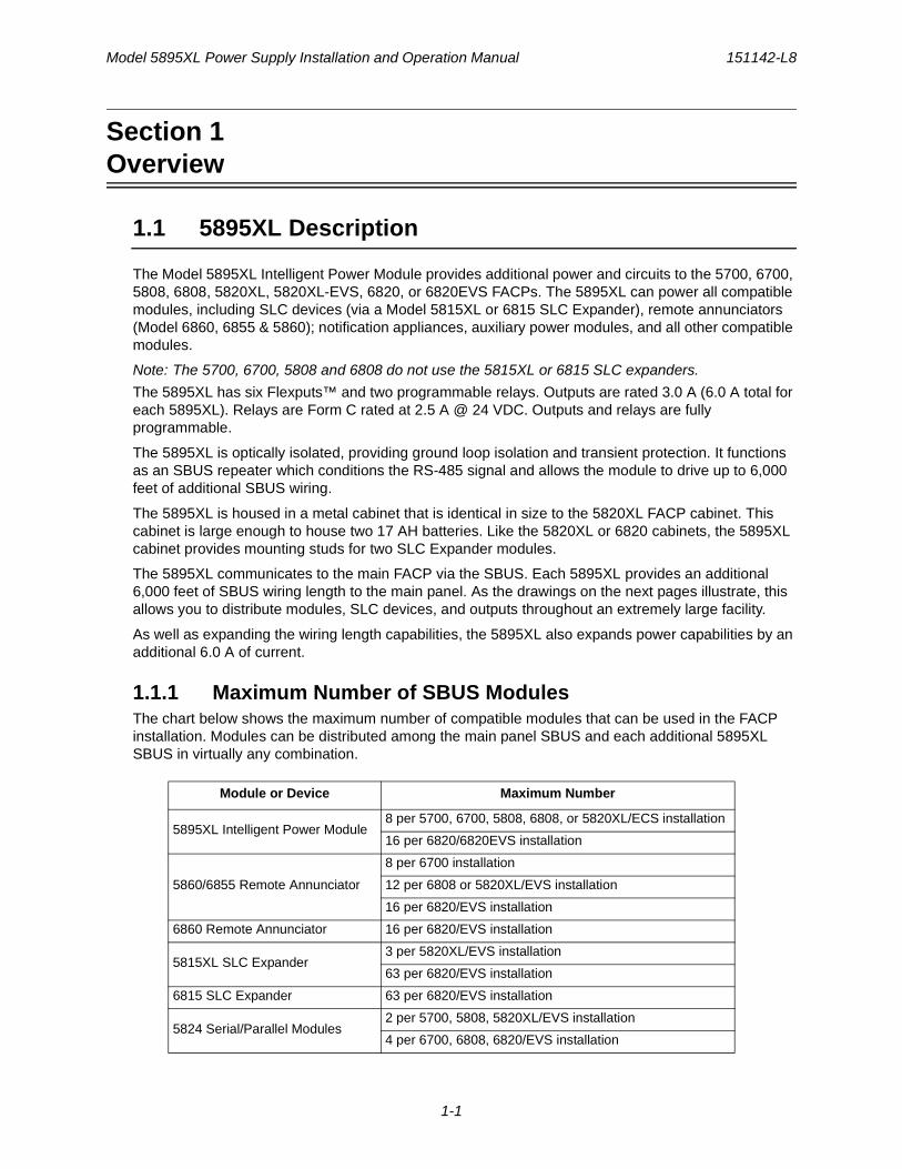
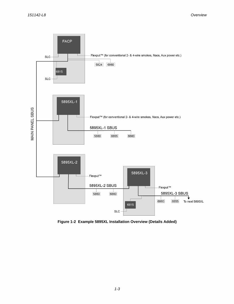
The Model 5895XL Intelligent Power Module provides additional power and circuits to the 5700, 6700, 5808, 6808, 5820XL, 5820XL-EVS, 6820, or 6820EVS FACPs. The 5895XL can power all compatible modules, including SLC devices (via a Model 5815XL or 6815 SLC Expander), remote annunciators (Model 6860, 6855 & 5860); notification appliances, auxiliary power modules, and all other compatible modules.
Note: The 5700, 6700, 5808 and 6808 do not use the 5815XL or 6815 SLC expanders.
The 5895XL has six Flexputs™ and two programmable relays. Outputs are rated 3.0 A (6.0 A total for each 5895XL). Relays are Form C rated at 2.5 A @ 24 VDC. Outputs and relays are fully programmable.
The 5895XL is optically isolated, providing ground loop isolation and transient protection. It functions as an SBUS repeater which conditions the RS-485 signal and allows the module to drive up to 6,000 feet of additional SBUS wiring.
The 5895XL is housed in a metal cabinet that is identical in size to the 5820XL FACP cabinet. This cabinet is large enough to house two 17 AH batteries. Like the 5820XL or 6820 cabinets, the 5895XL cabinet provides mounting studs for two SLC Expander modules.
The 5895XL communicates to the main FACP via the SBUS. Each 5895XL provides an additional 6,000 feet of SBUS wiring length to the main panel. As the drawings on the next pages illustrate, this allows you to distribute modules, SLC devices, and outputs throughout an extremely large facility.
As well as expanding the wiring length capabilities, the 5895XL also expands power capabilities by an additional 6.0 A of current.
1.1.1 Maximum Number of SBUS ModulesThe chart below shows the maximum number of compatible modules that can be used in the FACP installation. Modules can be distributed among the main panel SBUS and each additional 5895XL SBUS in virtually any combination.
Module or Device Maximum Number
5895XL Intelligent Power Module8 per 5700, 6700, 5808, 6808, or 5820XL/ECS installation
16 per 6820/6820EVS installation
5860/6855 Remote Annunciator
8 per 6700 installation
12 per 6808 or 5820XL/EVS installation
16 per 6820/EVS installation
6860 Remote Annunciator 16 per 6820/EVS installation
5815XL SLC Expander3 per 5820XL/EVS installation
63 per 6820/EVS installation
6815 SLC Expander 63 per 6820/EVS installation
5824 Serial/Parallel Modules2 per 5700, 5808, 5820XL/EVS installation
4 per 6700, 6808, 6820/EVS installation
Model 5895XL Power Supply Installation and Operation Manual 151142-L8
1-2
Figure 1-1 Example 5895XL Installation Overview
Outputs 6 per 5820XL, 6820/EVS or 5895XL
Conventional Relays 2 per 5820XL, 6820/EVS or 5895XL
151142-L8 Overview
1-3
Figure 1-2 Example 5895XL Installation Overview (Details Added)
Model 5895XL Power Supply Installation and Operation Manual 151142-L8
1-4
1.2 Agency Requirements
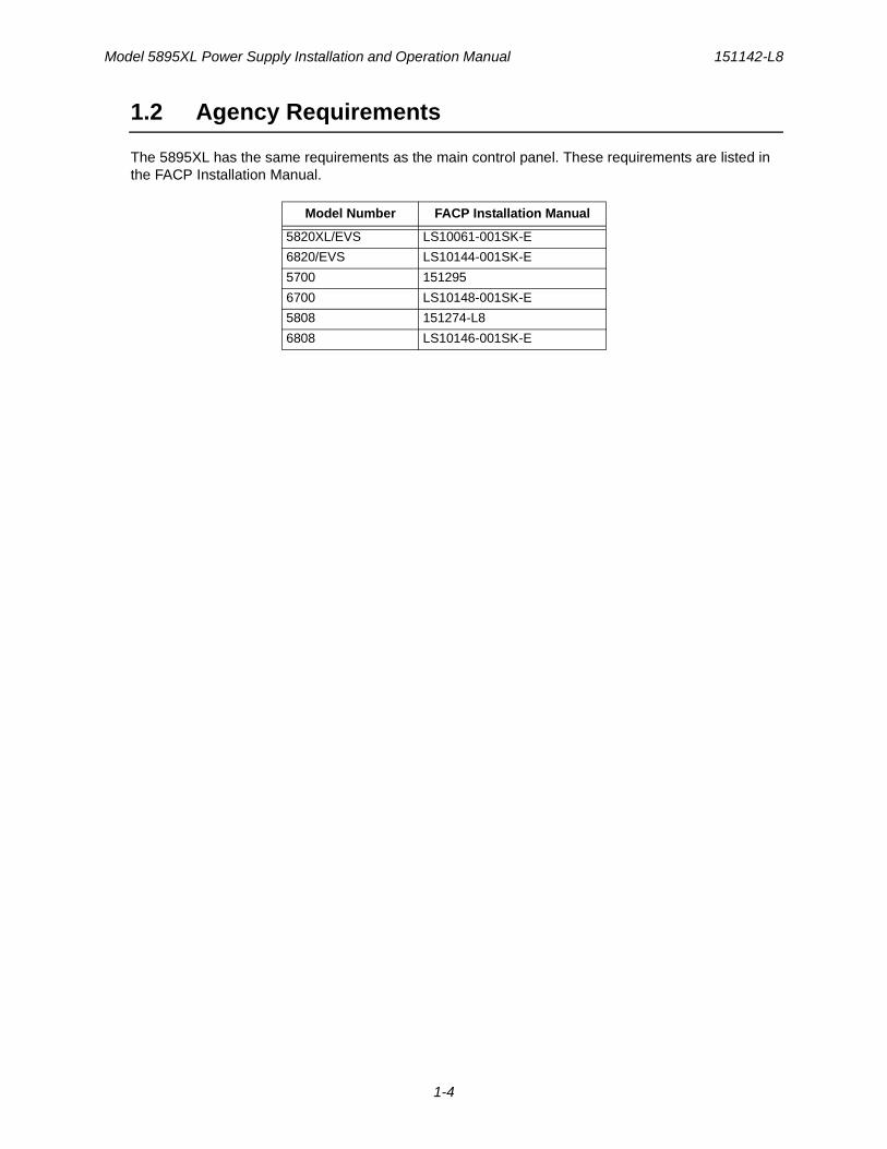
The 5895XL has the same requirements as the main control panel. These requirements are listed in the FACP Installation Manual.
Model Number FACP Installation Manual
5820XL/EVS LS10061-001SK-E
6820/EVS LS10144-001SK-E
5700 151295
6700 LS10148-001SK-E
5808 151274-L8
6808 LS10146-001SK-E

151142-L8
2-1
Section 2Before You Begin Installing
2.1 Inventory
The Model 5895XL ships with the following hardware:
• A cabinet with all hardware assembled
• Two keys for the front door
• Ten 4.7K ohm end-of-line resistors
Note: For UL installations 4.7kΩ end-of-line resistor (ordered separately) must be used.
• A battery cable for batteries wired in series
2.2 Environmental Specifications
It is important to protect the 5895XL control panel from water. To prevent water damage, the following precautions should be FOLLOWED when installing the units:
• Do not mount directly on exterior walls, especially masonry walls (condensation)
• Do not mount directly on exterior walls below grade (condensation)
• Protect from plumbing leaks
• Protect from splash caused by sprinkler system inspection ports
• Do not mount in areas with humidity-generating equipment (such as dryers, production machinery)
When selecting a location to mount the 5895XL, the unit should be mounted where it will NOT be exposed to temperatures outside the range of 0°C-49°C (32°F-120°F) or humidity outside the range of 10%-93% at 30°C (86°F) non-condensing.
2.3 Software Downloads
In order to supply the latest features and functionality in fire alarm and life safety technology to our customers, we make frequent upgrades to the embedded software in our products. To ensure that you are installing and programming the latest features, we strongly recommend that you download the most current version of software for each product prior to commissioning any system. Contact Honeywell Silent Knight Technical Support with any questions about software and the appropriate version for a specific application. Software updates can be found at www.silentknight.com
Model 5895XL Power Supply Installation and Operation Manual 151142-L8
2-2
2.4 5895XL Board and Terminal Strip Description
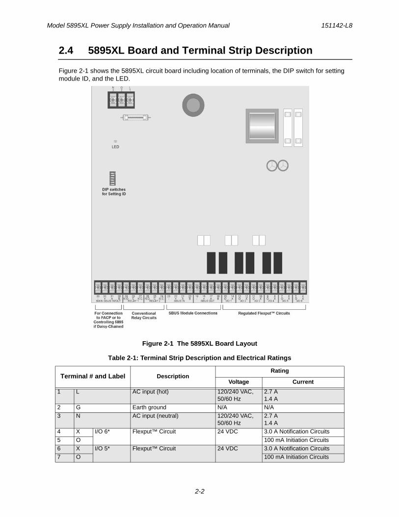
Figure 2-1 shows the 5895XL circuit board including location of terminals, the DIP switch for setting module ID, and the LED.
Figure 2-1 The 5895XL Board Layout
Table 2-1: Terminal Strip Description and Electrical Ratings
Terminal # and Label DescriptionRating
Voltage Current
1 L AC input (hot) 120/240 VAC, 50/60 Hz
2.7 A1.4 A
2 G Earth ground N/A N/A3 N AC input (neutral) 120/240 VAC,
50/60 Hz2.7 A1.4 A
4 X I/O 6* Flexput™ Circuit 24 VDC 3.0 A Notification Circuits
5 O 100 mA Initiation Circuits6 X I/O 5* Flexput™ Circuit 24 VDC 3.0 A Notification Circuits7 O 100 mA Initiation Circuits
151142-L8 Before You Begin Installing
2-3
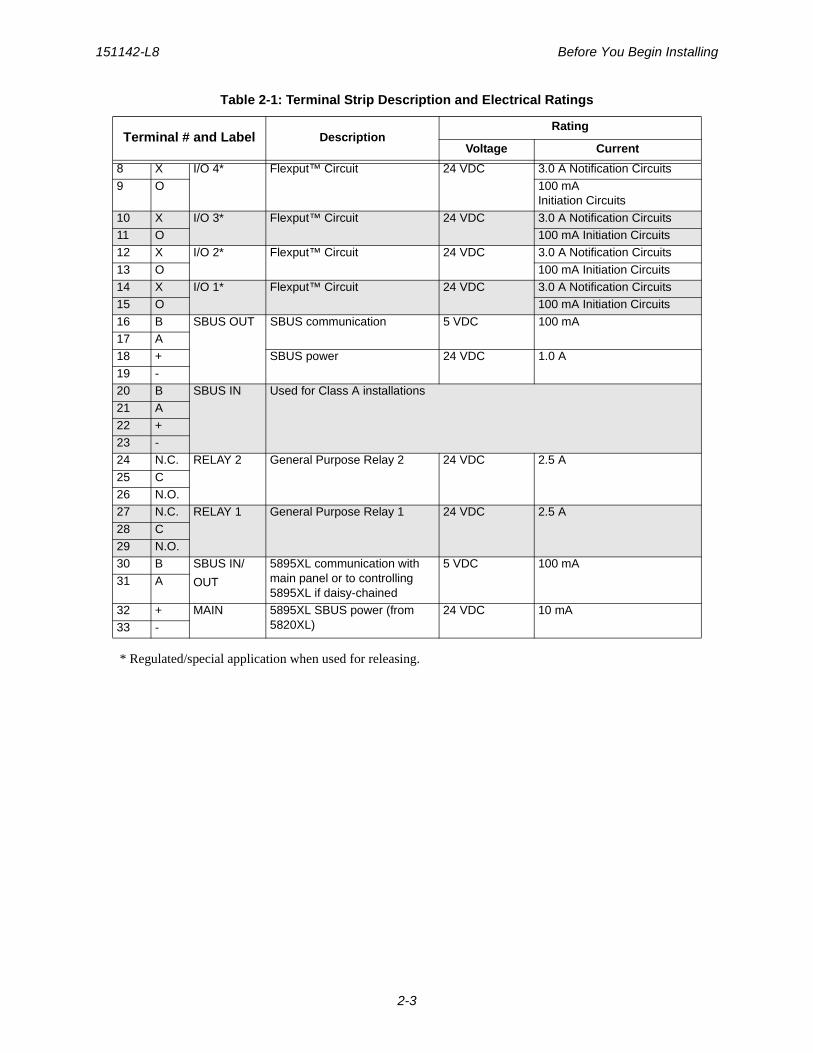
* Regulated/special application when used for releasing.
8 X I/O 4* Flexput™ Circuit 24 VDC 3.0 A Notification Circuits
9 O 100 mA Initiation Circuits
10 X I/O 3* Flexput™ Circuit 24 VDC 3.0 A Notification Circuits11 O 100 mA Initiation Circuits12 X I/O 2* Flexput™ Circuit 24 VDC 3.0 A Notification Circuits
13 O 100 mA Initiation Circuits14 X I/O 1* Flexput™ Circuit 24 VDC 3.0 A Notification Circuits15 O 100 mA Initiation Circuits
16 B SBUS OUT SBUS communication 5 VDC 100 mA17 A18 + SBUS power 24 VDC 1.0 A
19 -20 B SBUS IN Used for Class A installations21 A
22 +23 -24 N.C. RELAY 2 General Purpose Relay 2 24 VDC 2.5 A
25 C26 N.O.27 N.C. RELAY 1 General Purpose Relay 1 24 VDC 2.5 A
28 C29 N.O.30 B SBUS IN/
OUT
5895XL communication with main panel or to controlling 5895XL if daisy-chained
5 VDC 100 mA
31 A
32 + MAIN 5895XL SBUS power (from 5820XL)
24 VDC 10 mA33 -
Table 2-1: Terminal Strip Description and Electrical Ratings
Terminal # and Label DescriptionRating
Voltage Current
Model 5895XL Power Supply Installation and Operation Manual 151142-L8
2-4
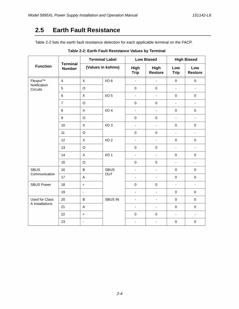
2.5 Earth Fault Resistance
Table 2-2 lists the earth fault resistance detection for each applicable terminal on the FACP.
Table 2-2: Earth Fault Resistance Values by Terminal
FunctionTerminal Number
Terminal Label Low Biased High Biased
(Values in kohms) High Trip
High Restore
Low Trip
Low Restore
Flexput™ NotificationCircuits
4 X I/O 6 - - 0 0
5 O 0 0 - -
6 X I/O 5 - - 0 0
7 O 0 0 - -
8 X I/O 4 - - 0 0
9 O 0 0 - -
10 X I/O 3 - - 0 0
11 O 0 0 - -
12 X I/O 2 - - 0 0
13 O 0 0 - -
14 X I/O 1 - - 0 0
15 O 0 0 - -
SBUS Communication
16 B SBUS OUT
- - 0 0
17 A - - 0 0
SBUS Power 18 + 0 0 - -
19 - - - 0 0
Used for Class A Installations
20 B SBUS IN - - 0 0
21 A - - 0 0
22 + 0 0 - -
23 - - - 0 0
151142-L8 Before You Begin Installing
2-5
2.6 Calculating Current Draw and Standby Battery
This section is for helping you determine the current draw and standby battery needs for your installation.
2.6.1 Worksheet RequirementsThe following steps must be taken when determining 5895XL current draw and standby battery requirements.
Filling in the Current Draw Worksheet, Table 2-4 (Section 2.6.2)1. For the 5895XL, the worst case current draw is listed for the panel, addressable devices, and SLC
expanders. Fill in the number of addressable devices and expanders that will be used in the system and compute the current draw requirements for alarm and standby. Record this information in Table 2-4 at Line A.
2. Add up the current draw for all auxiliary devices and record in the table at Line B.
3. Add up all notification appliance loads and record in the table at Line C.
4. For notification appliances and auxiliary devices not mentioned in the manual, refer to the device manual for the current ratings.
5. Make sure that the total alarm current you calculated, including current for the panel itself, does not exceed 6.0 A. This is the maximum alarm current allowable.
6. Complete the remaining instructions in Table 2-4 for determining battery size requirements.
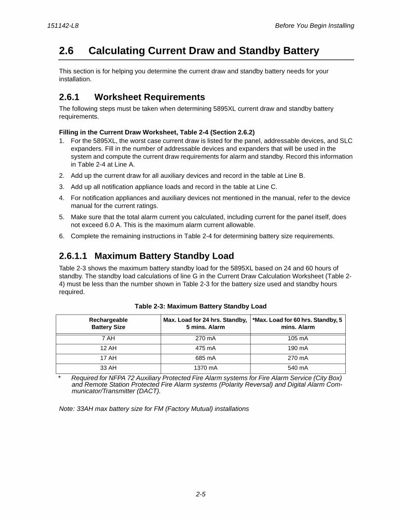
2.6.1.1 Maximum Battery Standby LoadTable 2-3 shows the maximum battery standby load for the 5895XL based on 24 and 60 hours of standby. The standby load calculations of line G in the Current Draw Calculation Worksheet (Table 2-4) must be less than the number shown in Table 2-3 for the battery size used and standby hours required.
Note: 33AH max battery size for FM (Factory Mutual) installations
Table 2-3: Maximum Battery Standby Load
RechargeableBattery Size
Max. Load for 24 hrs. Standby, 5 mins. Alarm
*Max. Load for 60 hrs. Standby, 5 mins. Alarm
7 AH 270 mA 105 mA
12 AH 475 mA 190 mA
17 AH 685 mA 270 mA
33 AH 1370 mA 540 mA
* Required for NFPA 72 Auxiliary Protected Fire Alarm systems for Fire Alarm Service (City Box) and Remote Station Protected Fire Alarm systems (Polarity Reversal) and Digital Alarm Com-municator/Transmitter (DACT).
Model 5895XL Power Supply Installation and Operation Manual 151142-L8
2-6
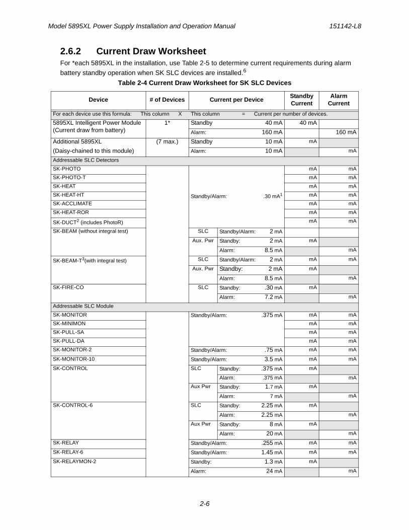
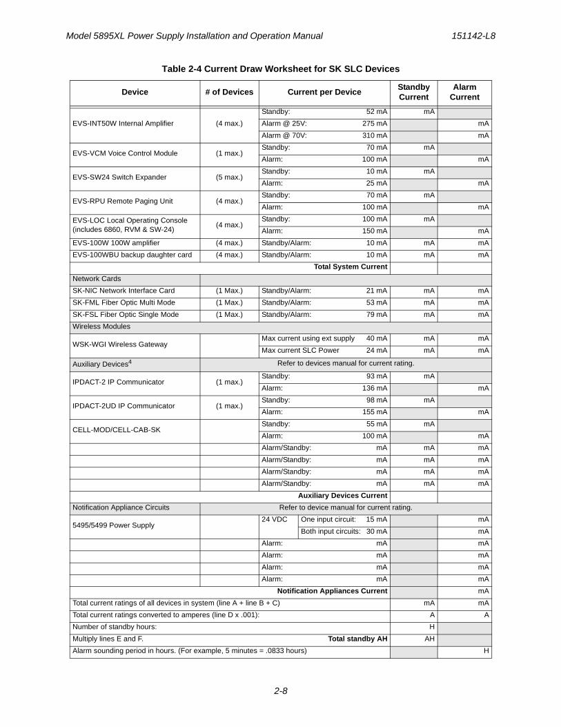
2.6.2 Current Draw WorksheetFor *each 5895XL in the installation, use Table 2-5 to determine current requirements during alarm
battery standby operation when SK SLC devices are installed.6
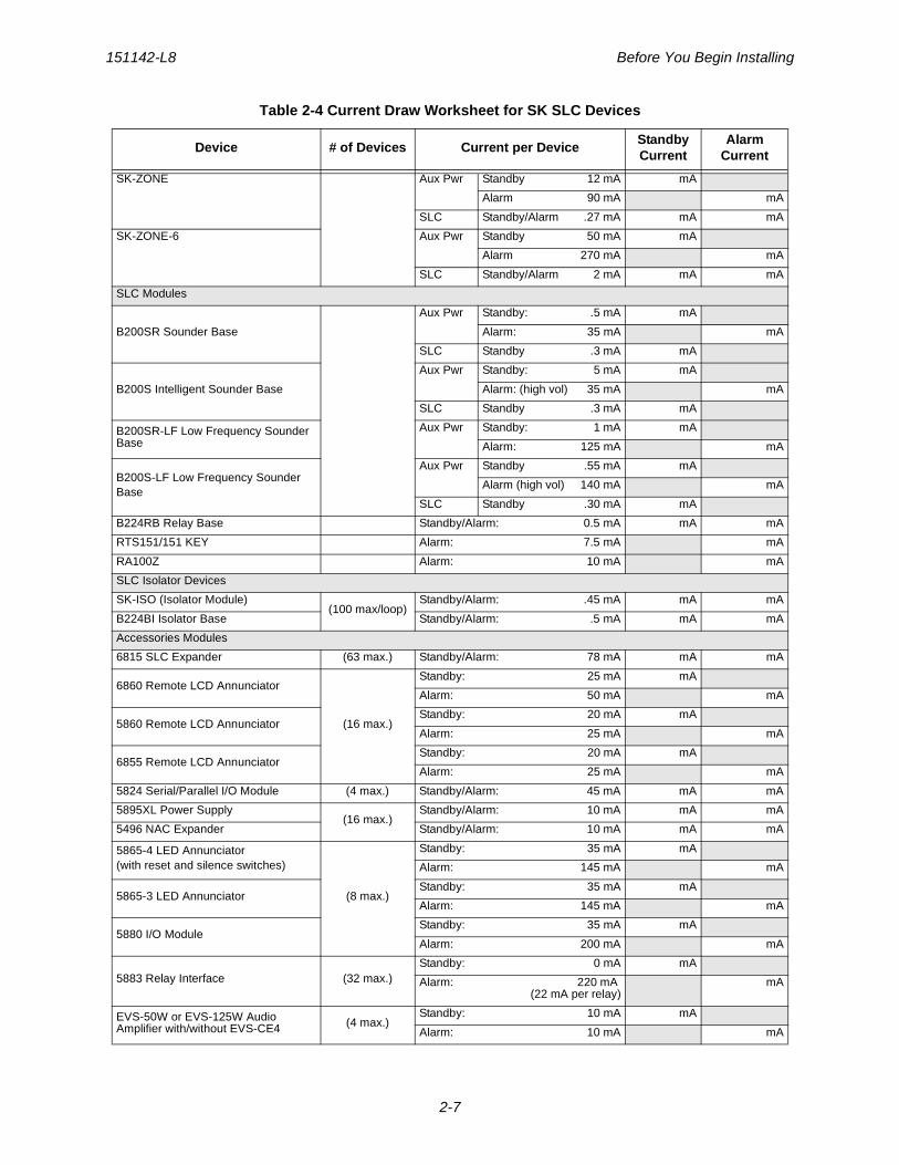
Table 2-4 Current Draw Worksheet for SK SLC Devices
Device # of Devices Current per DeviceStandby Current
Alarm Current
For each device use this formula: This column X This column = Current per number of devices.
5895XL Intelligent Power Module (Current draw from battery)
1* Standby 40 mA 40 mA
Alarm: 160 mA 160 mA
Additional 5895XL
(Daisy-chained to this module)
(7 max.) Standby 10 mA mA
Alarm: 10 mA mA
Addressable SLC Detectors
SK-PHOTO
Standby/Alarm: .30 mA1
mA mA
SK-PHOTO-T mA mA
SK-HEAT mA mA
SK-HEAT-HT mA mA
SK-ACCLIMATE mA mA
SK-HEAT-ROR mA mA
SK-DUCT2 (includes PhotoR) mA mA
SK-BEAM (without integral test) SLC Standby/Alarm: 2 mA
Aux. Pwr Standby: 2 mA mA
Alarm: 8.5 mA mA
SK-BEAM-T3(with integral test) SLC Standby/Alarm: 2 mA mA mA
Aux. Pwr Standby: 2 mA mA
Alarm: 8.5 mA mA
SK-FIRE-CO SLC Standby: .30 mA mA
Alarm: 7.2 mA mA
Addressable SLC Module
SK-MONITOR Standby/Alarm: .375 mA mA mA
SK-MINIMON mA mA
SK-PULL-SA mA mA
SK-PULL-DA mA mA
SK-MONITOR-2 Standby/Alarm: .75 mA mA mA
SK-MONITOR-10 Standby/Alarm: 3.5 mA mA mA
SK-CONTROL SLC Standby: .375 mA mA
Alarm: .375 mA mA
Aux Pwr Standby: 1.7 mA mA
Alarm: 7 mA mA
SK-CONTROL-6 SLC Standby: 2.25 mA mA
Alarm: 2.25 mA mA
Aux Pwr Standby: 8 mA mA
Alarm: 20 mA mA
SK-RELAY Standby/Alarm: .255 mA mA mA
SK-RELAY-6 Standby/Alarm: 1.45 mA mA mA
SK-RELAYMON-2 Standby: 1.3 mA mA
Alarm: 24 mA mA
151142-L8 Before You Begin Installing
2-7
SK-ZONE Aux Pwr Standby 12 mA mA
Alarm 90 mA mA
SLC Standby/Alarm .27 mA mA mA
SK-ZONE-6 Aux Pwr Standby 50 mA mA
Alarm 270 mA mA
SLC Standby/Alarm 2 mA mA mA
SLC Modules
B200SR Sounder Base
Aux Pwr Standby: .5 mA mA
Alarm: 35 mA mA
SLC Standby .3 mA mA
B200S Intelligent Sounder Base
Aux Pwr Standby: 5 mA mA
Alarm: (high vol) 35 mA mA
SLC Standby .3 mA mA
B200SR-LF Low Frequency Sounder Base
Aux Pwr Standby: 1 mA mA
Alarm: 125 mA mA
B200S-LF Low Frequency Sounder Base
Aux Pwr Standby .55 mA mA
Alarm (high vol) 140 mA mA
SLC Standby .30 mA mA
B224RB Relay Base Standby/Alarm: 0.5 mA mA mA
RTS151/151 KEY Alarm: 7.5 mA mA
RA100Z Alarm: 10 mA mA
SLC Isolator Devices
SK-ISO (Isolator Module)(100 max/loop)
Standby/Alarm: .45 mA mA mA
B224BI Isolator Base Standby/Alarm: .5 mA mA mA
Accessories Modules
6815 SLC Expander (63 max.) Standby/Alarm: 78 mA mA mA
6860 Remote LCD Annunciator
(16 max.)
Standby: 25 mA mA
Alarm: 50 mA mA
5860 Remote LCD AnnunciatorStandby: 20 mA mA
Alarm: 25 mA mA
6855 Remote LCD AnnunciatorStandby: 20 mA mA
Alarm: 25 mA mA
5824 Serial/Parallel I/O Module (4 max.) Standby/Alarm: 45 mA mA mA
5895XL Power Supply(16 max.)
Standby/Alarm: 10 mA mA mA
5496 NAC Expander Standby/Alarm: 10 mA mA mA
5865-4 LED Annunciator(with reset and silence switches)
(8 max.)
Standby: 35 mA mA
Alarm: 145 mA mA
5865-3 LED AnnunciatorStandby: 35 mA mA
Alarm: 145 mA mA
5880 I/O ModuleStandby: 35 mA mA
Alarm: 200 mA mA
5883 Relay Interface (32 max.)Standby: 0 mA mA
Alarm: 220 mA (22 mA per relay)
mA
EVS-50W or EVS-125W Audio Amplifier with/without EVS-CE4 (4 max.)
Standby: 10 mA mA
Alarm: 10 mA mA
Table 2-4 Current Draw Worksheet for SK SLC Devices
Device # of Devices Current per DeviceStandby Current
Alarm Current
Model 5895XL Power Supply Installation and Operation Manual 151142-L8
2-8
EVS-INT50W Internal Amplifier (4 max.)
Standby: 52 mA mA
Alarm @ 25V: 275 mA mA
Alarm @ 70V: 310 mA mA
EVS-VCM Voice Control Module (1 max.)Standby: 70 mA mA
Alarm: 100 mA mA
EVS-SW24 Switch Expander (5 max.)Standby: 10 mA mA
Alarm: 25 mA mA
EVS-RPU Remote Paging Unit (4 max.)Standby: 70 mA mA
Alarm: 100 mA mA
EVS-LOC Local Operating Console (includes 6860, RVM & SW-24)
(4 max.)Standby: 100 mA mA
Alarm: 150 mA mA
EVS-100W 100W amplifier (4 max.) Standby/Alarm: 10 mA mA mA
EVS-100WBU backup daughter card (4 max.) Standby/Alarm: 10 mA mA mA
Total System Current
Network Cards
SK-NIC Network Interface Card (1 Max.) Standby/Alarm: 21 mA mA mA
SK-FML Fiber Optic Multi Mode (1 Max.) Standby/Alarm: 53 mA mA mA
SK-FSL Fiber Optic Single Mode (1 Max.) Standby/Alarm: 79 mA mA mA
Wireless Modules
WSK-WGI Wireless GatewayMax current using ext supply 40 mA mA mA
Max current SLC Power 24 mA mA mA
Auxiliary Devices4 Refer to devices manual for current rating.
IPDACT-2 IP Communicator (1 max.)Standby: 93 mA mA
Alarm: 136 mA mA
IPDACT-2UD IP Communicator (1 max.)Standby: 98 mA mA
Alarm: 155 mA mA
CELL-MOD/CELL-CAB-SKStandby: 55 mA mA
Alarm: 100 mA mA
Alarm/Standby: mA mA mA
Alarm/Standby: mA mA mA
Alarm/Standby: mA mA mA
Alarm/Standby: mA mA mA
Auxiliary Devices Current
Notification Appliance Circuits Refer to device manual for current rating.
5495/5499 Power Supply24 VDC One input circuit: 15 mA mA
Both input circuits: 30 mA mA
Alarm: mA mA
Alarm: mA mA
Alarm: mA mA
Alarm: mA mA
Notification Appliances Current mA
Total current ratings of all devices in system (line A + line B + C) mA mA
Total current ratings converted to amperes (line D x .001): A A
Number of standby hours: H
Multiply lines E and F. Total standby AH AH
Alarm sounding period in hours. (For example, 5 minutes = .0833 hours) H
Table 2-4 Current Draw Worksheet for SK SLC Devices
Device # of Devices Current per DeviceStandby Current
Alarm Current
151142-L8 Before You Begin Installing
2-9
1. The FACP can only support 5 devices w/LED’s on. This current draw has been added to the panels alarm current.
2. The SK-DUCT housing contains a vacant mount for a SK-RELAY (sold separately). Current draw for the SK-RELAY is calculated by increasing the SK-RELAY row of the calculation sheet by one for each SK-RELAY used with a SK-DUCT.
3. SK-BEAM-T draws a maximum of 500mA from Auxiliary power only when the test feature is used. this should be considered when determining auxiliary power capacity but not calculated into current requirements for day to day operation.
4. If using door holders, you do not need to consider door holder current for alarm/battery standby, because power is removed during that time. However, during normal operation, door holders draw current and must be included in the 6.0A total current that can be drawn from the panel.
5. Use next size battery with capacity greater than required.
6. Total does not include isolator devices or accessory bases.
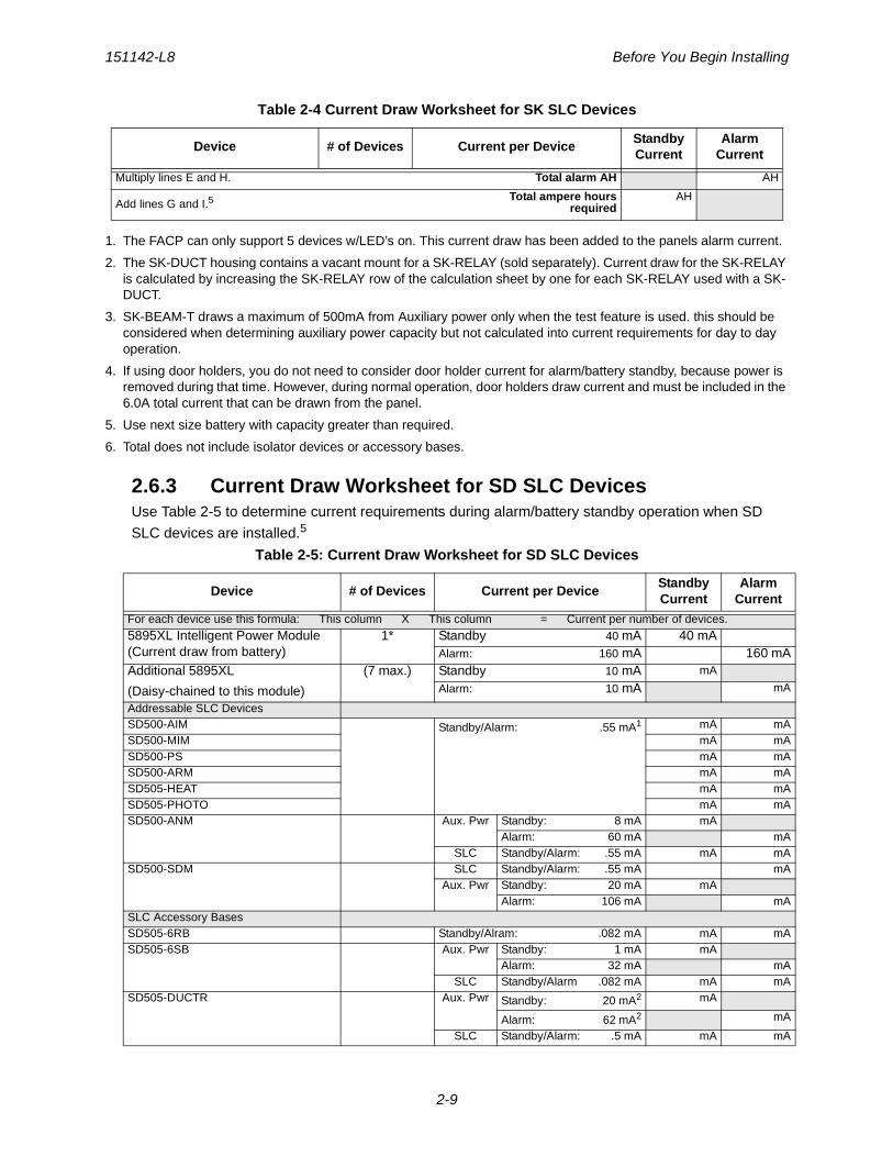
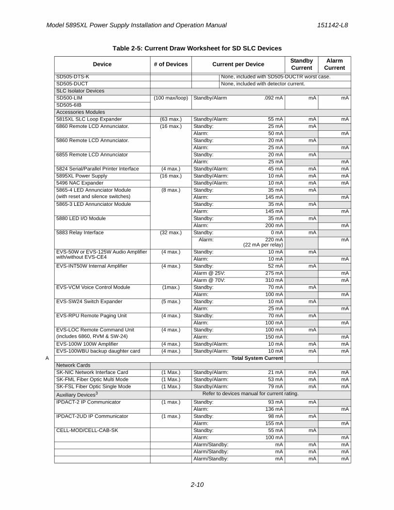
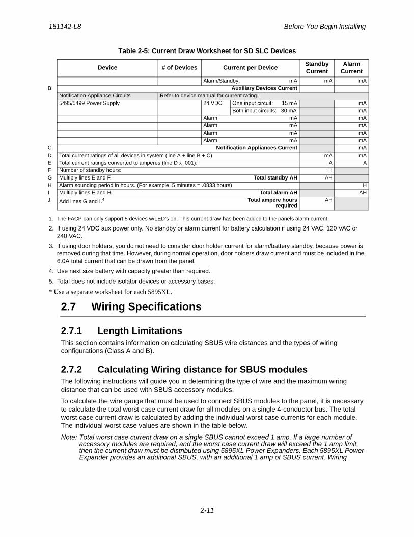
2.6.3 Current Draw Worksheet for SD SLC DevicesUse Table 2-5 to determine current requirements during alarm/battery standby operation when SD
SLC devices are installed.5
Multiply lines E and H. Total alarm AH AH
Add lines G and I.5Total ampere hours
requiredAH
Table 2-5: Current Draw Worksheet for SD SLC Devices
Device # of Devices Current per DeviceStandby Current
Alarm Current
For each device use this formula: This column X This column = Current per number of devices.
5895XL Intelligent Power Module (Current draw from battery)
1* Standby 40 mA 40 mAAlarm: 160 mA 160 mA
Additional 5895XL
(Daisy-chained to this module)
(7 max.) Standby 10 mA mA
Alarm: 10 mA mA
Addressable SLC DevicesSD500-AIM Standby/Alarm: .55 mA1 mA mASD500-MIM mA mASD500-PS mA mASD500-ARM mA mASD505-HEAT mA mASD505-PHOTO mA mASD500-ANM Aux. Pwr Standby: 8 mA mA
Alarm: 60 mA mASLC Standby/Alarm: .55 mA mA mA
SD500-SDM SLC Standby/Alarm: .55 mA mAAux. Pwr Standby: 20 mA mA
Alarm: 106 mA mASLC Accessory BasesSD505-6RB Standby/Alram: .082 mA mA mASD505-6SB Aux. Pwr Standby: 1 mA mA
Alarm: 32 mA mASLC Standby/Alarm .082 mA mA mA
SD505-DUCTR Aux. Pwr Standby: 20 mA2 mA
Alarm: 62 mA2 mA
SLC Standby/Alarm: .5 mA mA mA
Table 2-4 Current Draw Worksheet for SK SLC Devices
Device # of Devices Current per DeviceStandby Current
Alarm Current
Model 5895XL Power Supply Installation and Operation Manual 151142-L8
2-10
SD505-DTS-K None, included with SD505-DUCTR worst case.SD505-DUCT None, included with detector current.SLC Isolator DevicesSD500-LIM (100 max/loop) Standby/Alarm .092 mA mA mASD505-6IBAccessories Modules5815XL SLC Loop Expander (63 max.) Standby/Alarm: 55 mA mA mA6860 Remote LCD Annunciator. (16 max.) Standby: 25 mA mA
Alarm: 50 mA mA5860 Remote LCD Annunciator. Standby: 20 mA mA
Alarm: 25 mA mA6855 Remote LCD Annunciator Standby: 20 mA mA
Alarm: 25 mA mA5824 Serial/Parallel Printer Interface (4 max.) Standby/Alarm: 45 mA mA mA5895XL Power Supply (16 max.) Standby/Alarm: 10 mA mA mA5496 NAC Expander Standby/Alarm: 10 mA mA mA5865-4 LED Annunciator Module(with reset and silence switches)
(8 max.) Standby: 35 mA mAAlarm: 145 mA mA
5865-3 LED Annunciator Module Standby: 35 mA mAAlarm: 145 mA mA
5880 LED I/O Module Standby: 35 mA mAAlarm: 200 mA mA
5883 Relay Interface (32 max.) Standby: 0 mA mAAlarm: 220 mA
(22 mA per relay)mA
EVS-50W or EVS-125W Audio Amplifier with/without EVS-CE4
(4 max.) Standby: 10 mA mAAlarm: 10 mA mA
EVS-INT50W Internal Amplifier (4 max.) Standby: 52 mA mAAlarm @ 25V: 275 mA mAAlarm @ 70V: 310 mA mA
EVS-VCM Voice Control Module (1max.) Standby: 70 mA mAAlarm: 100 mA mA
EVS-SW24 Switch Expander (5 max.) Standby: 10 mA mAAlarm: 25 mA mA
EVS-RPU Remote Paging Unit (4 max.) Standby: 70 mA mAAlarm: 100 mA mA
EVS-LOC Remote Command Unit (includes 6860, RVM & SW-24)
(4 max.) Standby: 100 mA mAAlarm: 150 mA mA
EVS-100W 100W Amplifier (4 max.) Standby/Alarm: 10 mA mA mAEVS-100WBU backup daughter card (4 max.) Standby/Alarm: 10 mA mA mA
A Total System CurrentNetwork CardsSK-NIC Network Interface Card (1 Max.) Standby/Alarm: 21 mA mA mASK-FML Fiber Optic Multi Mode (1 Max.) Standby/Alarm: 53 mA mA mASK-FSL Fiber Optic Single Mode (1 Max.) Standby/Alarm: 79 mA mA mA
Auxiliary Devices3 Refer to devices manual for current rating.
IPDACT-2 IP Communicator (1 max.) Standby: 93 mA mAAlarm: 136 mA mA
IPDACT-2UD IP Communicator (1 max.) Standby: 98 mA mAAlarm: 155 mA mA
CELL-MOD/CELL-CAB-SK Standby: 55 mA mAAlarm: 100 mA mAAlarm/Standby: mA mA mAAlarm/Standby: mA mA mAAlarm/Standby: mA mA mA
Table 2-5: Current Draw Worksheet for SD SLC Devices
Device # of Devices Current per DeviceStandby Current
Alarm Current
151142-L8 Before You Begin Installing
2-11
1. The FACP can only support 5 devices w/LED’s on. This current draw has been added to the panels alarm current.
2. If using 24 VDC aux power only. No standby or alarm current for battery calculation if using 24 VAC, 120 VAC or 240 VAC.
3. If using door holders, you do not need to consider door holder current for alarm/battery standby, because power is removed during that time. However, during normal operation, door holders draw current and must be included in the 6.0A total current that can be drawn from the panel.
4. Use next size battery with capacity greater than required.
5. Total does not include isolator devices or accessory bases.
* Use a separate worksheet for each 5895XL.
2.7 Wiring Specifications
2.7.1 Length LimitationsThis section contains information on calculating SBUS wire distances and the types of wiring configurations (Class A and B).
2.7.2 Calculating Wiring distance for SBUS modulesThe following instructions will guide you in determining the type of wire and the maximum wiring distance that can be used with SBUS accessory modules.
To calculate the wire gauge that must be used to connect SBUS modules to the panel, it is necessary to calculate the total worst case current draw for all modules on a single 4-conductor bus. The total worst case current draw is calculated by adding the individual worst case currents for each module. The individual worst case values are shown in the table below.
Note: Total worst case current draw on a single SBUS cannot exceed 1 amp. If a large number of accessory modules are required, and the worst case current draw will exceed the 1 amp limit, then the current draw must be distributed using 5895XL Power Expanders. Each 5895XL Power Expander provides an additional SBUS, with an additional 1 amp of SBUS current. Wiring
Alarm/Standby: mA mA mAB Auxiliary Devices Current
Notification Appliance Circuits Refer to device manual for current rating.5495/5499 Power Supply 24 VDC One input circuit: 15 mA mA
Both input circuits: 30 mA mAAlarm: mA mAAlarm: mA mAAlarm: mA mAAlarm: mA mA
C Notification Appliances Current mAD Total current ratings of all devices in system (line A + line B + C) mA mAE Total current ratings converted to amperes (line D x .001): A AF Number of standby hours: HG Multiply lines E and F. Total standby AH AHH Alarm sounding period in hours. (For example, 5 minutes = .0833 hours) HI Multiply lines E and H. Total alarm AH AHJ Add lines G and I.4 Total ampere hours
requiredAH
Table 2-5: Current Draw Worksheet for SD SLC Devices
Device # of Devices Current per DeviceStandby Current
Alarm Current
Model 5895XL Power Supply Installation and Operation Manual 151142-L8
2-12
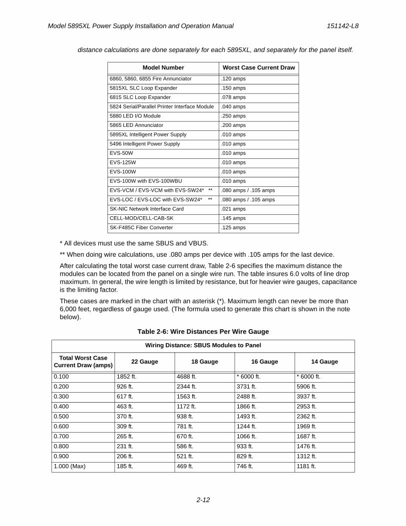
distance calculations are done separately for each 5895XL, and separately for the panel itself.
* All devices must use the same SBUS and VBUS.
** When doing wire calculations, use .080 amps per device with .105 amps for the last device.
After calculating the total worst case current draw, Table 2-6 specifies the maximum distance the modules can be located from the panel on a single wire run. The table insures 6.0 volts of line drop maximum. In general, the wire length is limited by resistance, but for heavier wire gauges, capacitance is the limiting factor.
These cases are marked in the chart with an asterisk (*). Maximum length can never be more than 6,000 feet, regardless of gauge used. (The formula used to generate this chart is shown in the note below).
Model Number Worst Case Current Draw
6860, 5860, 6855 Fire Annunciator .120 amps
5815XL SLC Loop Expander .150 amps
6815 SLC Loop Expander .078 amps
5824 Serial/Parallel Printer Interface Module .040 amps
5880 LED I/O Module .250 amps
5865 LED Annunciator .200 amps
5895XL Intelligent Power Supply .010 amps
5496 Intelligent Power Supply .010 amps
EVS-50W .010 amps
EVS-125W .010 amps
EVS-100W .010 amps
EVS-100W with EVS-100WBU .010 amps
EVS-VCM / EVS-VCM with EVS-SW24* ** .080 amps / .105 amps
EVS-LOC / EVS-LOC with EVS-SW24* ** .080 amps / .105 amps
SK-NIC Network Interface Card .021 amps
CELL-MOD/CELL-CAB-SK .145 amps
SK-F485C Fiber Converter .125 amps
Table 2-6: Wire Distances Per Wire Gauge
Wiring Distance: SBUS Modules to Panel
Total Worst Case Current Draw (amps)
22 Gauge 18 Gauge 16 Gauge 14 Gauge
0.100 1852 ft. 4688 ft. * 6000 ft. * 6000 ft.
0.200 926 ft. 2344 ft. 3731 ft. 5906 ft.
0.300 617 ft. 1563 ft. 2488 ft. 3937 ft.
0.400 463 ft. 1172 ft. 1866 ft. 2953 ft.
0.500 370 ft. 938 ft. 1493 ft. 2362 ft.
0.600 309 ft. 781 ft. 1244 ft. 1969 ft.
0.700 265 ft. 670 ft. 1066 ft. 1687 ft.
0.800 231 ft. 586 ft. 933 ft. 1476 ft.
0.900 206 ft. 521 ft. 829 ft. 1312 ft.
1.000 (Max) 185 ft. 469 ft. 746 ft. 1181 ft.
151142-L8 Before You Begin Installing
2-13
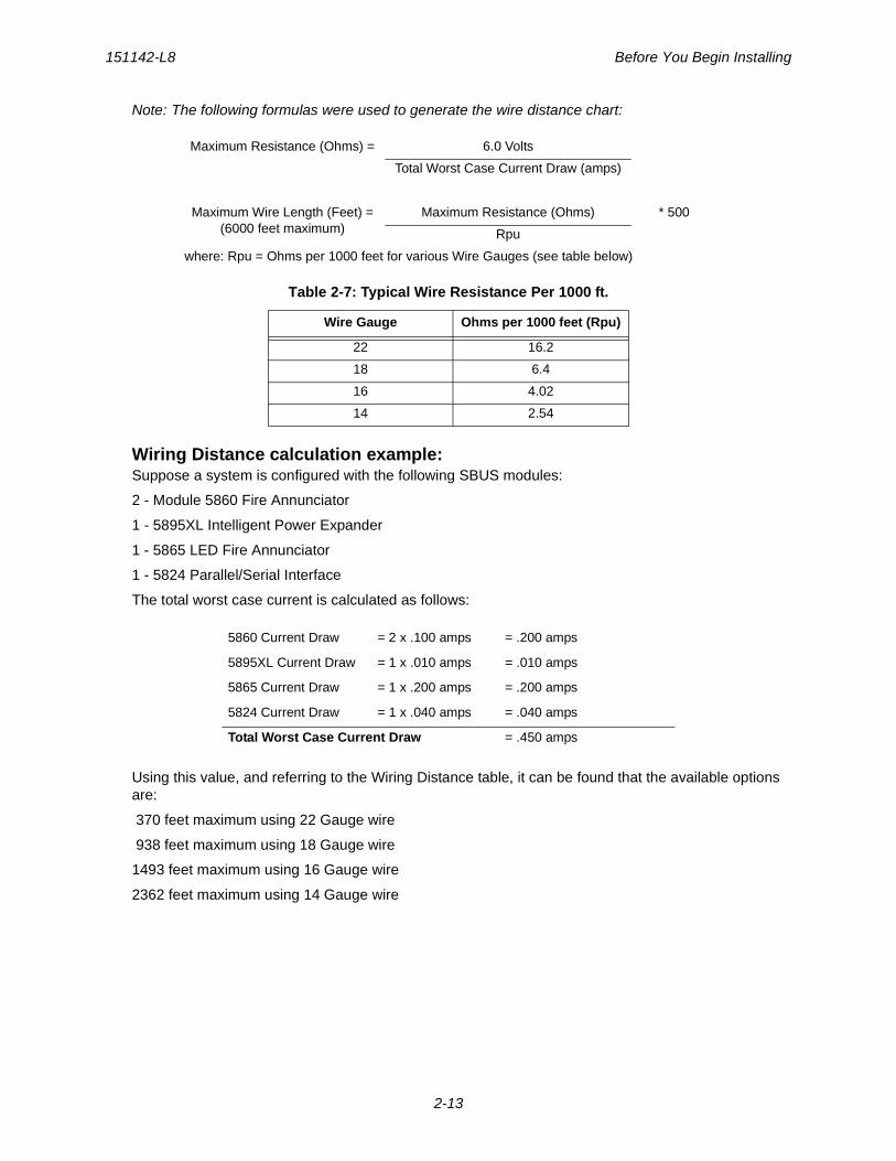
Note: The following formulas were used to generate the wire distance chart:
Wiring Distance calculation example:Suppose a system is configured with the following SBUS modules:
2 - Module 5860 Fire Annunciator
1 - 5895XL Intelligent Power Expander
1 - 5865 LED Fire Annunciator
1 - 5824 Parallel/Serial Interface
The total worst case current is calculated as follows:
Using this value, and referring to the Wiring Distance table, it can be found that the available options are:
370 feet maximum using 22 Gauge wire
938 feet maximum using 18 Gauge wire
1493 feet maximum using 16 Gauge wire
2362 feet maximum using 14 Gauge wire
Maximum Resistance (Ohms) = 6.0 Volts
Total Worst Case Current Draw (amps)
Maximum Wire Length (Feet) =(6000 feet maximum)
Maximum Resistance (Ohms) * 500
Rpu
where: Rpu = Ohms per 1000 feet for various Wire Gauges (see table below)
Table 2-7: Typical Wire Resistance Per 1000 ft.
Wire Gauge Ohms per 1000 feet (Rpu)
22 16.2
18 6.4
16 4.02
14 2.54
5860 Current Draw = 2 x .100 amps = .200 amps
5895XL Current Draw = 1 x .010 amps = .010 amps
5865 Current Draw = 1 x .200 amps = .200 amps
5824 Current Draw = 1 x .040 amps = .040 amps
Total Worst Case Current Draw = .450 amps
Model 5895XL Power Supply Installation and Operation Manual 151142-L8
2-14
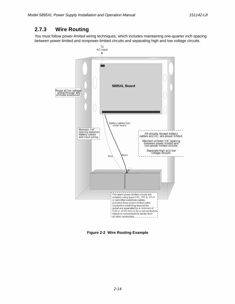
2.7.3 Wire RoutingYou must follow power-limited wiring techniques, which includes maintaining one-quarter inch spacing between power-limited and nonpower-limited circuits and separating high and low voltage circuits.
Figure 2-2 Wire Routing Example
5895XL Board
Model 5895XL Power Supply Installation and Operation Manual 151142-L8
3-1
Section 3Hardware Installation
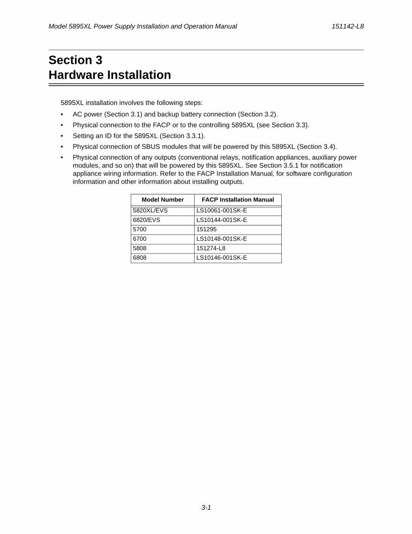
5895XL installation involves the following steps:
• AC power (Section 3.1) and backup battery connection (Section 3.2).
• Physical connection to the FACP or to the controlling 5895XL (see Section 3.3).
• Setting an ID for the 5895XL (Section 3.3.1).
• Physical connection of SBUS modules that will be powered by this 5895XL (Section 3.4).
• Physical connection of any outputs (conventional relays, notification appliances, auxiliary power modules, and so on) that will be powered by this 5895XL. See Section 3.5.1 for notification appliance wiring information. Refer to the FACP Installation Manual, for software configuration information and other information about installing outputs.
Model Number FACP Installation Manual
5820XL/EVS LS10061-001SK-E
6820/EVS LS10144-001SK-E
5700 151295
6700 LS10148-001SK-E
5808 151274-L8
6808 LS10146-001SK-E
Model 5895XL Power Supply Installation and Operation Manual 151142-L8
3-2
3.1 AC Power
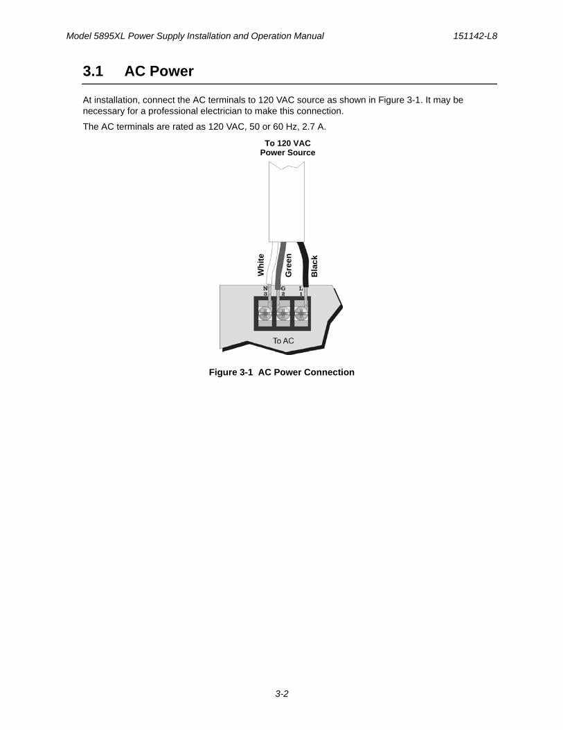
At installation, connect the AC terminals to 120 VAC source as shown in Figure 3-1. It may be necessary for a professional electrician to make this connection.
The AC terminals are rated as 120 VAC, 50 or 60 Hz, 2.7 A.
Figure 3-1 AC Power Connection
To 120 VACPower Source
Gre
en
Wh
ite
Bla
ck
151142-L8 Hardware Installation
3-3
3.2 Battery Connection
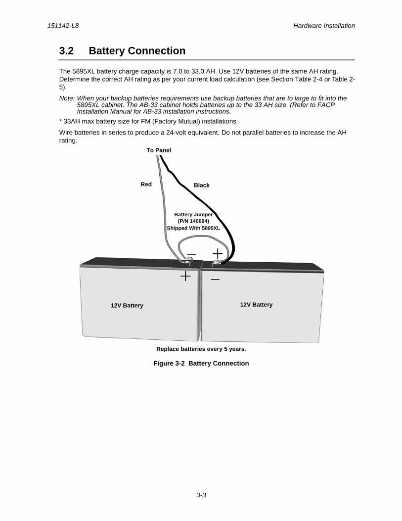
The 5895XL battery charge capacity is 7.0 to 33.0 AH. Use 12V batteries of the same AH rating. Determine the correct AH rating as per your current load calculation (see Section Table 2-4 or Table 2-5).
Note: When your backup batteries requirements use backup batteries that are to large to fit into the 5895XL cabinet. The AB-33 cabinet holds batteries up to the 33 AH size. (Refer to FACP Installation Manual for AB-33 installation instructions.
* 33AH max battery size for FM (Factory Mutual) installations
Wire batteries in series to produce a 24-volt equivalent. Do not parallel batteries to increase the AH rating.
Figure 3-2 Battery Connection
Red
To Panel
Black
12V Battery12V Battery
Battery Jumper(P/N 140694)
Shipped With 5895XL
Replace batteries every 5 years.
Model 5895XL Power Supply Installation and Operation Manual 151142-L8
3-4
3.3 Connecting the 5895XL to the FACP
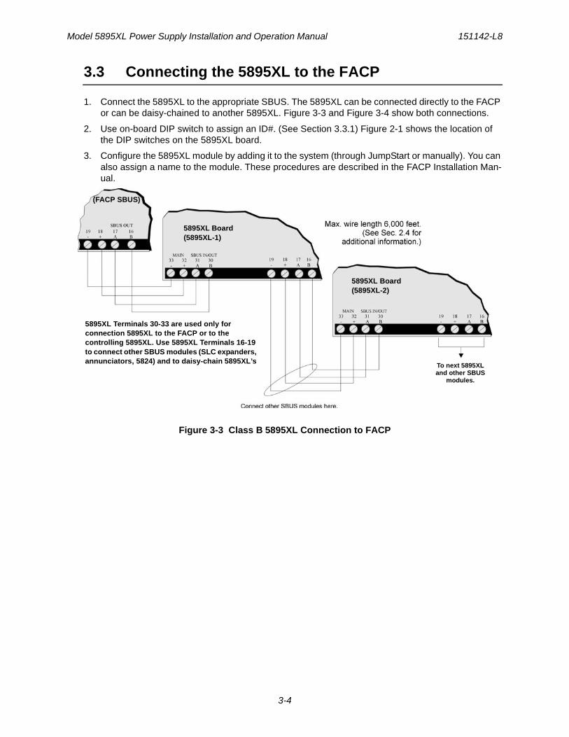
1. Connect the 5895XL to the appropriate SBUS. The 5895XL can be connected directly to the FACP or can be daisy-chained to another 5895XL. Figure 3-3 and Figure 3-4 show both connections.
2. Use on-board DIP switch to assign an ID#. (See Section 3.3.1) Figure 2-1 shows the location of the DIP switches on the 5895XL board.
3. Configure the 5895XL module by adding it to the system (through JumpStart or manually). You can also assign a name to the module. These procedures are described in the FACP Installation Man-ual.
Figure 3-3 Class B 5895XL Connection to FACP
(FACP SBUS)
5895XL Terminals 30-33 are used only for connection 5895XL to the FACP or to the controlling 5895XL. Use 5895XL Terminals 16-19 to connect other SBUS modules (SLC expanders, annunciators, 5824) and to daisy-chain 5895XL’s
5895XL Board(5895XL-1)
5895XL Board(5895XL-2)
To next 5895XL and other SBUS
modules.
151142-L8 Hardware Installation
3-5
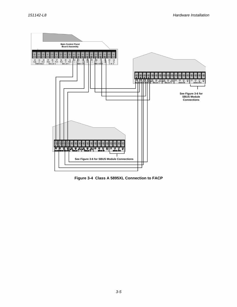
Figure 3-4 Class A 5895XL Connection to FACP
See Figure 3-6 for SBUS Module Connections
See Figure 3-6 for SBUS Module Connections
Model 5895XL Power Supply Installation and Operation Manual 151142-L8
3-6
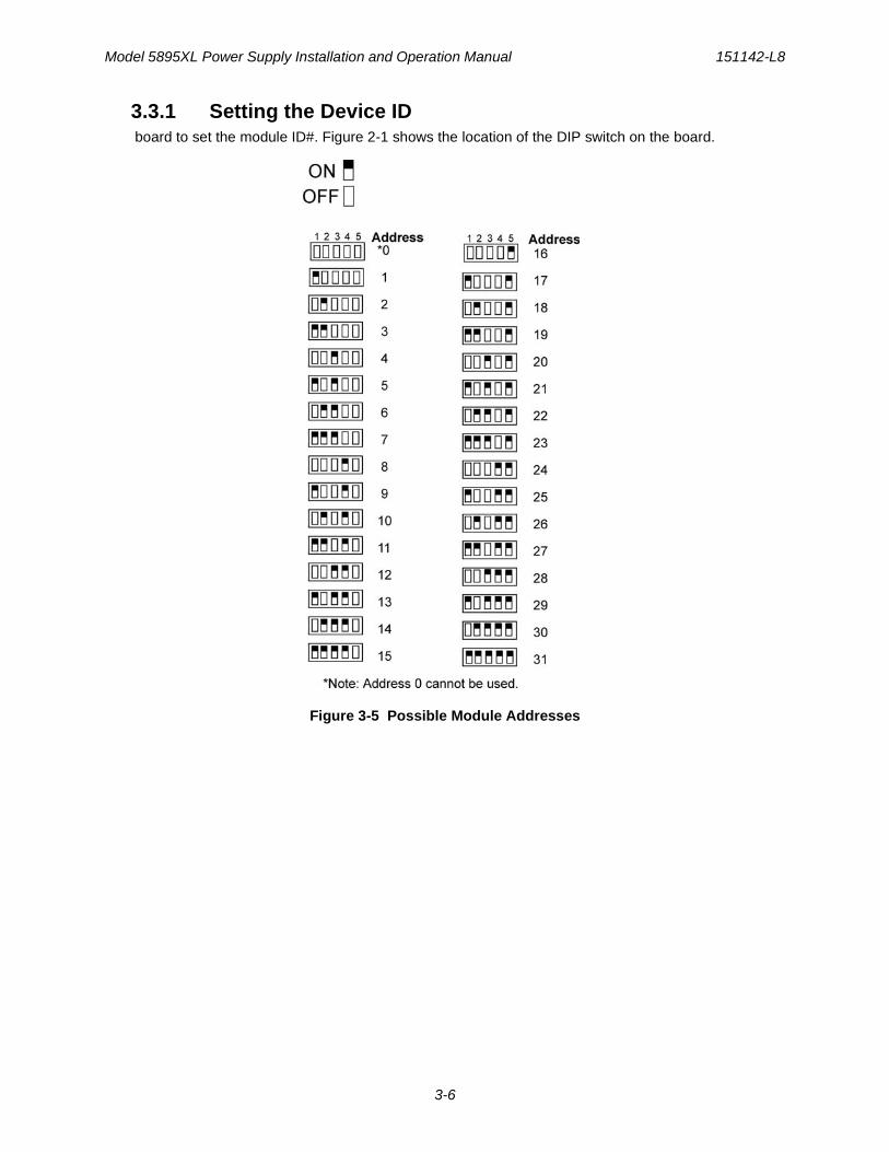
3.3.1 Setting the Device ID board to set the module ID#. Figure 2-1 shows the location of the DIP switch on the board.
Figure 3-5 Possible Module Addresses
151142-L8 Hardware Installation
3-7
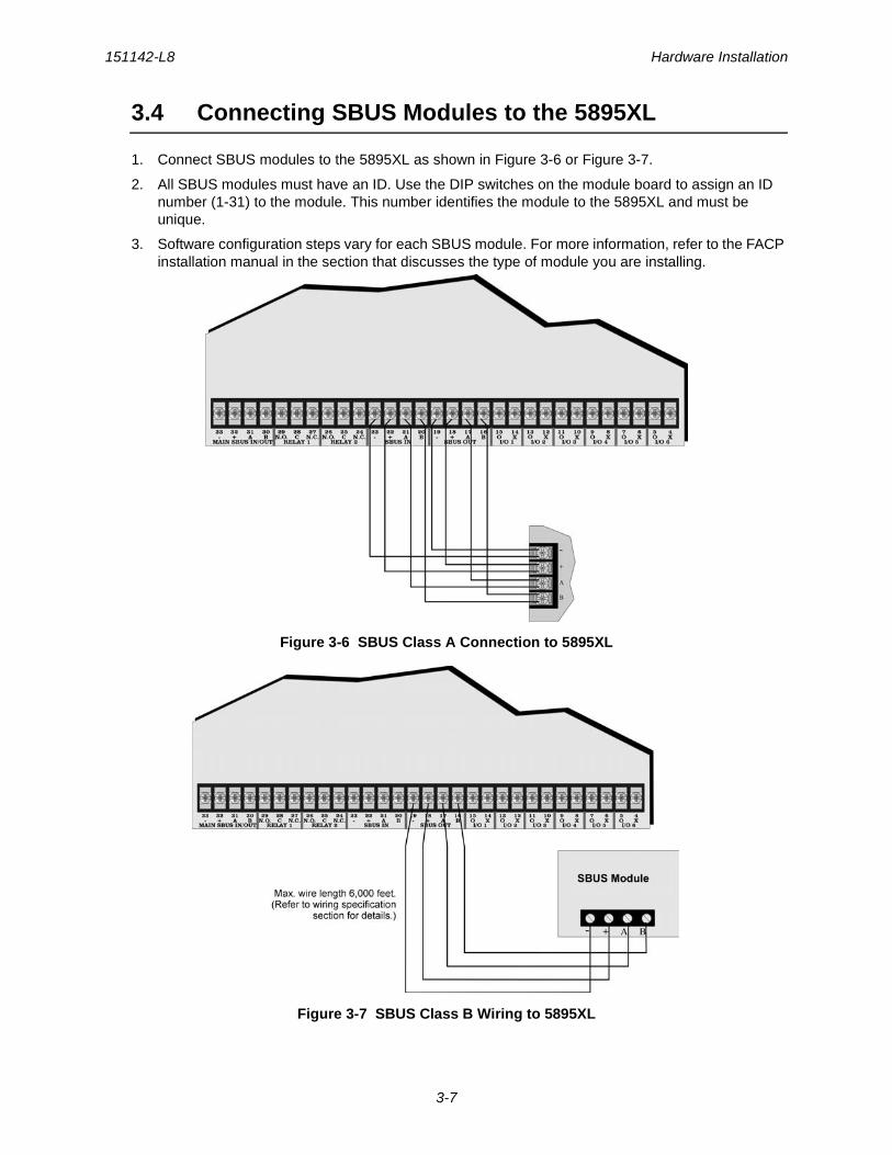
3.4 Connecting SBUS Modules to the 5895XL
1. Connect SBUS modules to the 5895XL as shown in Figure 3-6 or Figure 3-7.
2. All SBUS modules must have an ID. Use the DIP switches on the module board to assign an ID number (1-31) to the module. This number identifies the module to the 5895XL and must be unique.
3. Software configuration steps vary for each SBUS module. For more information, refer to the FACP installation manual in the section that discusses the type of module you are installing.
Figure 3-6 SBUS Class A Connection to 5895XL
Figure 3-7 SBUS Class B Wiring to 5895XL
Model 5895XL Power Supply Installation and Operation Manual 151142-L8
3-8
3.5 Flexputs™ I/O Circuits
The six Flexput™ circuits are an innovative and versatile feature of the 5895XL panel. They can be used as: Class A or B notification circuits, Class A or B initiation circuits (either 2 or 4 wire detectors), or as auxiliary power (resettable, continuous, or door holder).
This section of the manual explains how to install conventional notification appliances and initiating devices to be used with the 5895XL.
3.5.1 Conventional Notification ApplianceThis sub-section of the manual explains how to install conventional notification appliances for Class A and Class B configurations.
3.5.2 Releasing OperationsApproved releasing solenoids are list in Table 3-1. Do not mix cross alarming zones with smoke verification zones. There must be at least two automatic detection devices in each protected space. Spacing must be reduced to 0.7 times the linear spacing in accordance with NFPA 72.
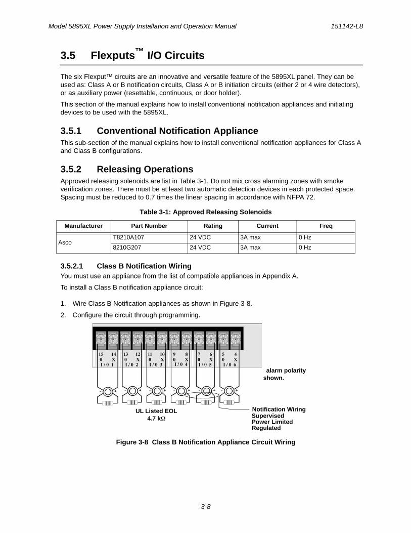
3.5.2.1 Class B Notification WiringYou must use an appliance from the list of compatible appliances in Appendix A.
To install a Class B notification appliance circuit:
1. Wire Class B Notification appliances as shown in Figure 3-8.
2. Configure the circuit through programming.
Figure 3-8 Class B Notification Appliance Circuit Wiring
Table 3-1: Approved Releasing Solenoids
Manufacturer Part Number Rating Current Freq
AscoT8210A107 24 VDC 3A max 0 Hz
8210G207 24 VDC 3A max 0 Hz
alarm polarity shown.
UL Listed EOL4.7 kΩ Supervised
Power Limited
Notification Wiring
Regulated
151142-L8 Hardware Installation
3-9
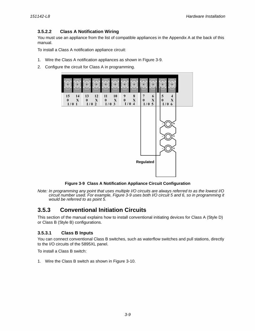
3.5.2.2 Class A Notification WiringYou must use an appliance from the list of compatible appliances in the Appendix A at the back of this manual.
To install a Class A notification appliance circuit:
1. Wire the Class A notification appliances as shown in Figure 3-9.
2. Configure the circuit for Class A in programming.
Figure 3-9 Class A Notification Appliance Circuit Configuration
Note: In programming any point that uses multiple I/O circuits are always referred to as the lowest I/O circuit number used. For example, Figure 3-9 uses both I/O circuit 5 and 6, so in programming it would be referred to as point 5.
3.5.3 Conventional Initiation CircuitsThis section of the manual explains how to install conventional initiating devices for Class A (Style D) or Class B (Style B) configurations.
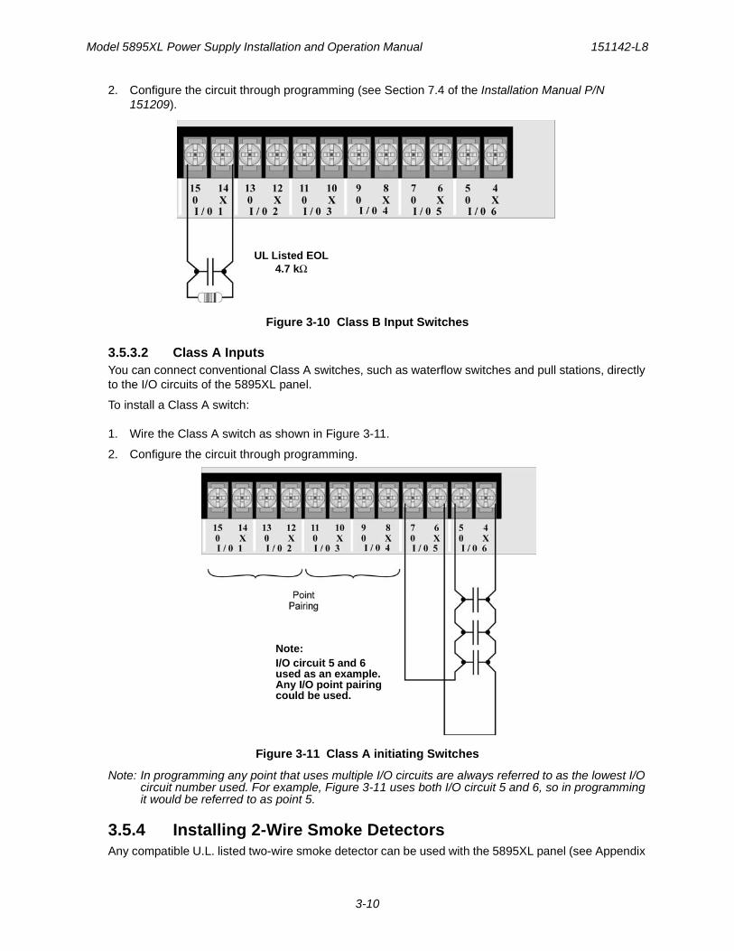
3.5.3.1 Class B InputsYou can connect conventional Class B switches, such as waterflow switches and pull stations, directly to the I/O circuits of the 5895XL panel.
To install a Class B switch:
1. Wire the Class B switch as shown in Figure 3-10.
Regulated
Model 5895XL Power Supply Installation and Operation Manual 151142-L8
3-10
2. Configure the circuit through programming (see Section 7.4 of the Installation Manual P/N 151209).
Figure 3-10 Class B Input Switches
3.5.3.2 Class A InputsYou can connect conventional Class A switches, such as waterflow switches and pull stations, directly to the I/O circuits of the 5895XL panel.
To install a Class A switch:
1. Wire the Class A switch as shown in Figure 3-11.
2. Configure the circuit through programming.
Figure 3-11 Class A initiating Switches
Note: In programming any point that uses multiple I/O circuits are always referred to as the lowest I/O circuit number used. For example, Figure 3-11 uses both I/O circuit 5 and 6, so in programming it would be referred to as point 5.
3.5.4 Installing 2-Wire Smoke DetectorsAny compatible U.L. listed two-wire smoke detector can be used with the 5895XL panel (see Appendix
UL Listed EOL4.7 kΩ
Note:I/O circuit 5 and 6used as an example.Any I/O point pairingcould be used.
151142-L8 Hardware Installation
3-11
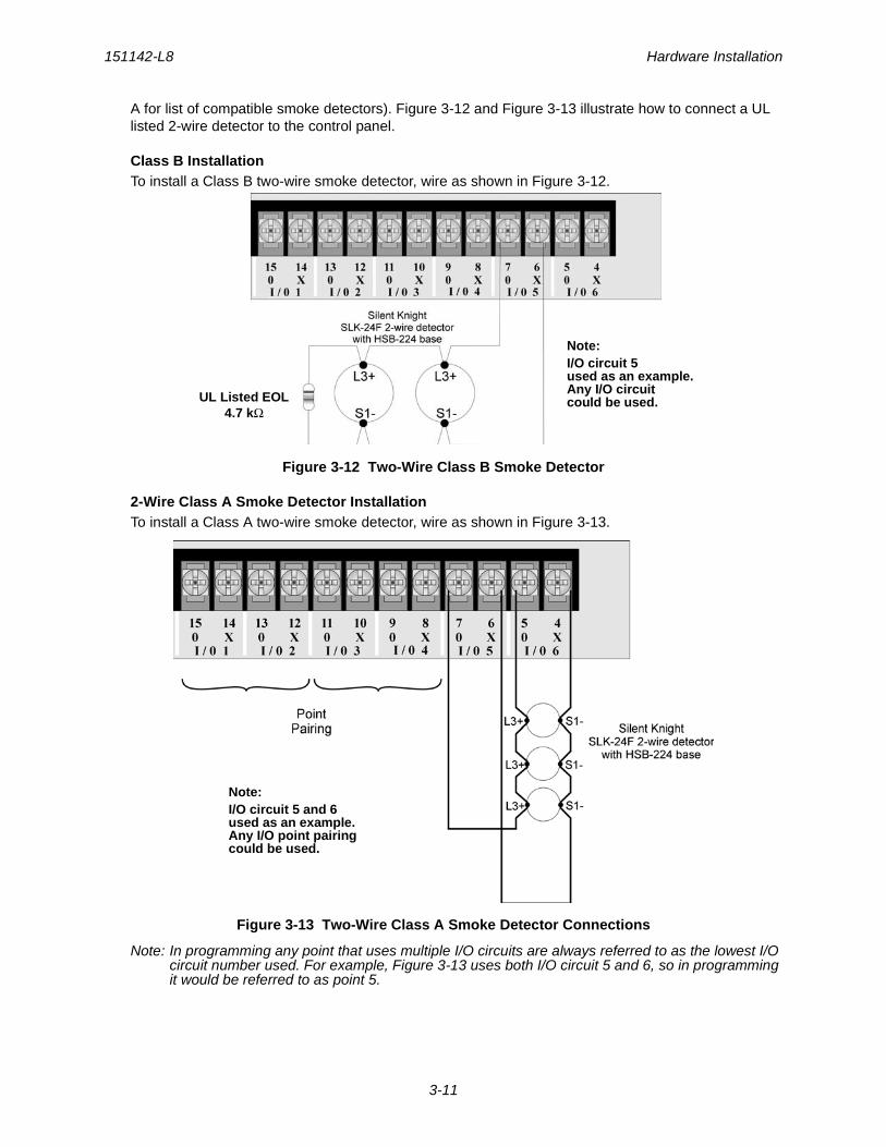
A for list of compatible smoke detectors). Figure 3-12 and Figure 3-13 illustrate how to connect a UL listed 2-wire detector to the control panel.
Class B InstallationTo install a Class B two-wire smoke detector, wire as shown in Figure 3-12.
Figure 3-12 Two-Wire Class B Smoke Detector
2-Wire Class A Smoke Detector InstallationTo install a Class A two-wire smoke detector, wire as shown in Figure 3-13.
Figure 3-13 Two-Wire Class A Smoke Detector Connections
Note: In programming any point that uses multiple I/O circuits are always referred to as the lowest I/O circuit number used. For example, Figure 3-13 uses both I/O circuit 5 and 6, so in programming it would be referred to as point 5.
Note:I/O circuit 5used as an example.Any I/O circuitcould be used.UL Listed EOL
4.7 kΩ
Note:I/O circuit 5 and 6used as an example.Any I/O point pairingcould be used.
Model 5895XL Power Supply Installation and Operation Manual 151142-L8
3-12
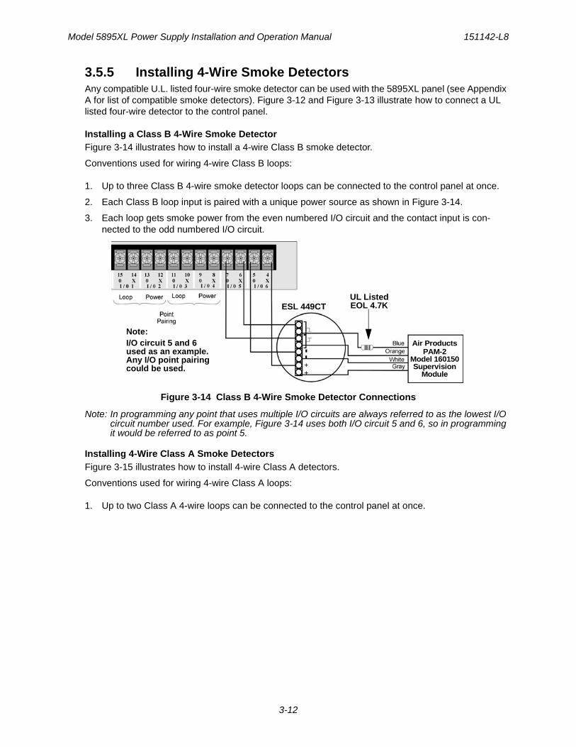
3.5.5 Installing 4-Wire Smoke DetectorsAny compatible U.L. listed four-wire smoke detector can be used with the 5895XL panel (see Appendix A for list of compatible smoke detectors). Figure 3-12 and Figure 3-13 illustrate how to connect a UL listed four-wire detector to the control panel.
Installing a Class B 4-Wire Smoke DetectorFigure 3-14 illustrates how to install a 4-wire Class B smoke detector.
Conventions used for wiring 4-wire Class B loops:
1. Up to three Class B 4-wire smoke detector loops can be connected to the control panel at once.
2. Each Class B loop input is paired with a unique power source as shown in Figure 3-14.
3. Each loop gets smoke power from the even numbered I/O circuit and the contact input is con-nected to the odd numbered I/O circuit.
Figure 3-14 Class B 4-Wire Smoke Detector Connections
Note: In programming any point that uses multiple I/O circuits are always referred to as the lowest I/O circuit number used. For example, Figure 3-14 uses both I/O circuit 5 and 6, so in programming it would be referred to as point 5.
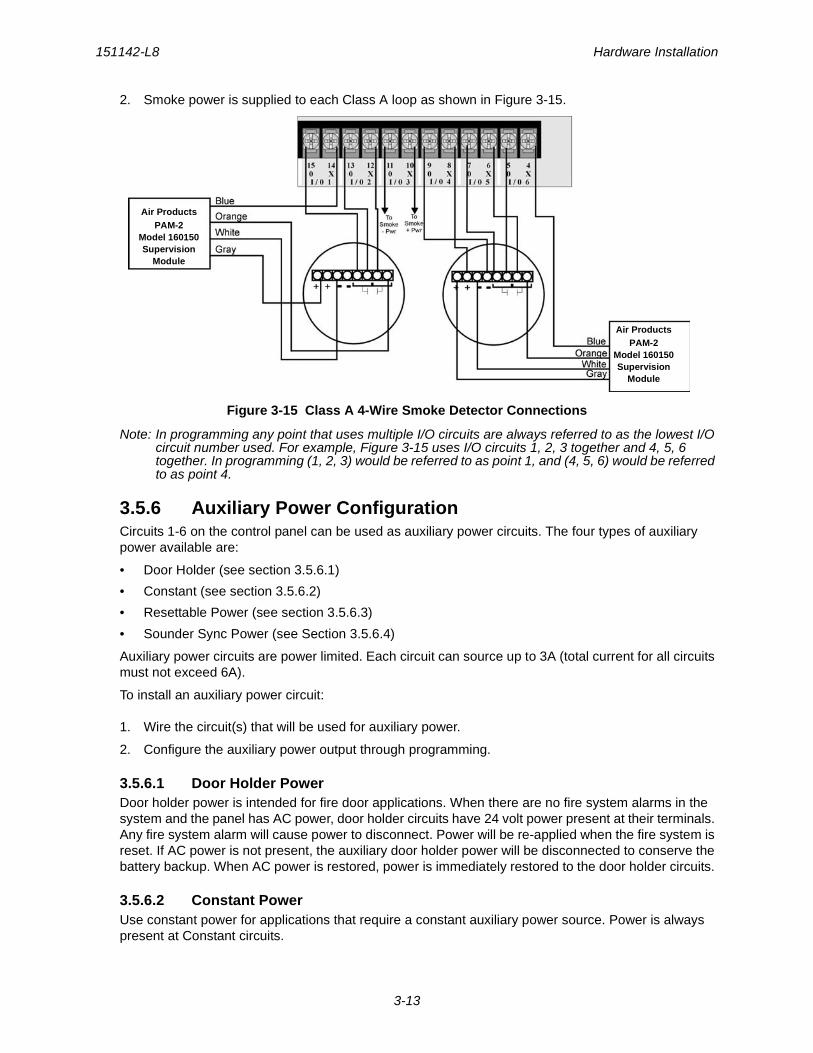
Installing 4-Wire Class A Smoke DetectorsFigure 3-15 illustrates how to install 4-wire Class A detectors.
Conventions used for wiring 4-wire Class A loops:
1. Up to two Class A 4-wire loops can be connected to the control panel at once.
Air ProductsPAM-2
Model 160150Supervision
Module
UL ListedEOL 4.7KESL 449CT
Note:I/O circuit 5 and 6used as an example.Any I/O point pairingcould be used.
151142-L8 Hardware Installation
3-13
2. Smoke power is supplied to each Class A loop as shown in Figure 3-15.
Figure 3-15 Class A 4-Wire Smoke Detector Connections
Note: In programming any point that uses multiple I/O circuits are always referred to as the lowest I/O circuit number used. For example, Figure 3-15 uses I/O circuits 1, 2, 3 together and 4, 5, 6 together. In programming (1, 2, 3) would be referred to as point 1, and (4, 5, 6) would be referred to as point 4.
3.5.6 Auxiliary Power ConfigurationCircuits 1-6 on the control panel can be used as auxiliary power circuits. The four types of auxiliary power available are:
• Door Holder (see section 3.5.6.1)
• Constant (see section 3.5.6.2)
• Resettable Power (see section 3.5.6.3)
• Sounder Sync Power (see Section 3.5.6.4)
Auxiliary power circuits are power limited. Each circuit can source up to 3A (total current for all circuits must not exceed 6A).
To install an auxiliary power circuit:
1. Wire the circuit(s) that will be used for auxiliary power.
2. Configure the auxiliary power output through programming.
3.5.6.1 Door Holder PowerDoor holder power is intended for fire door applications. When there are no fire system alarms in the system and the panel has AC power, door holder circuits have 24 volt power present at their terminals. Any fire system alarm will cause power to disconnect. Power will be re-applied when the fire system is reset. If AC power is not present, the auxiliary door holder power will be disconnected to conserve the battery backup. When AC power is restored, power is immediately restored to the door holder circuits.
3.5.6.2 Constant PowerUse constant power for applications that require a constant auxiliary power source. Power is always present at Constant circuits.
Air ProductsPAM-2
Model 160150Supervision
Module
Air ProductsPAM-2
Model 160150Supervision
Module
Model 5895XL Power Supply Installation and Operation Manual 151142-L8
3-14
3.5.6.3 Resettable PowerResettable power is typically used to power beam detectors, flame detectors and conventional 4-wire smoke detectors. For circuits selected as Resettable, 24-volt power is always present at the terminals unless a system reset occurs. If a system reset occurs, power is disconnected from the terminals for 30 seconds, then re-applied.
3.5.6.4 Sounder Sync PowerSounder Sync Power continuously outputs the System Sensor synchronization pattern and is intended for use with B200S sounder bases.
3.6 Conventional Relay Installation
5895XL relay circuits are installed in exactly the same way as the FACP relay circuits. Refer to the FACP Installation Manual for information on installing conventional relays.
151142 A-1
Appendix ACompatible Devices
A.1 Notification Appliances
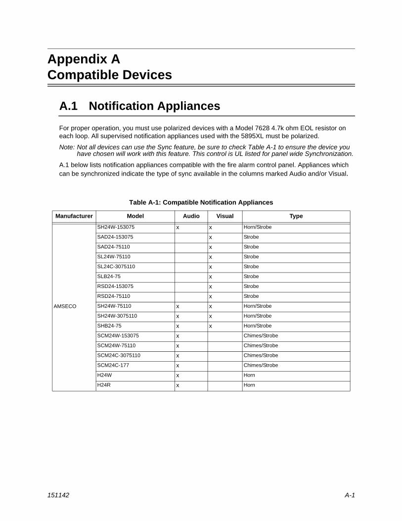
For proper operation, you must use polarized devices with a Model 7628 4.7k ohm EOL resistor on each loop. All supervised notification appliances used with the 5895XL must be polarized.
Note: Not all devices can use the Sync feature, be sure to check Table A-1 to ensure the device you have chosen will work with this feature. This control is UL listed for panel wide Synchronization.
A.1 below lists notification appliances compatible with the fire alarm control panel. Appliances which can be synchronized indicate the type of sync available in the columns marked Audio and/or Visual.
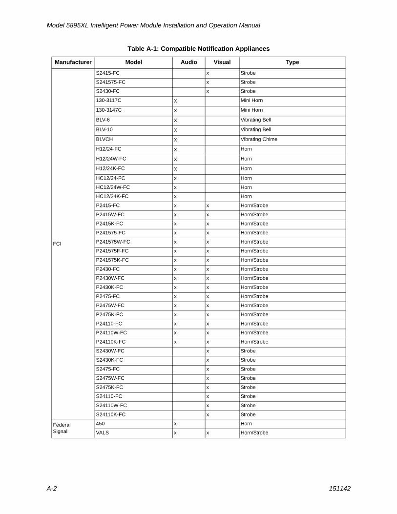
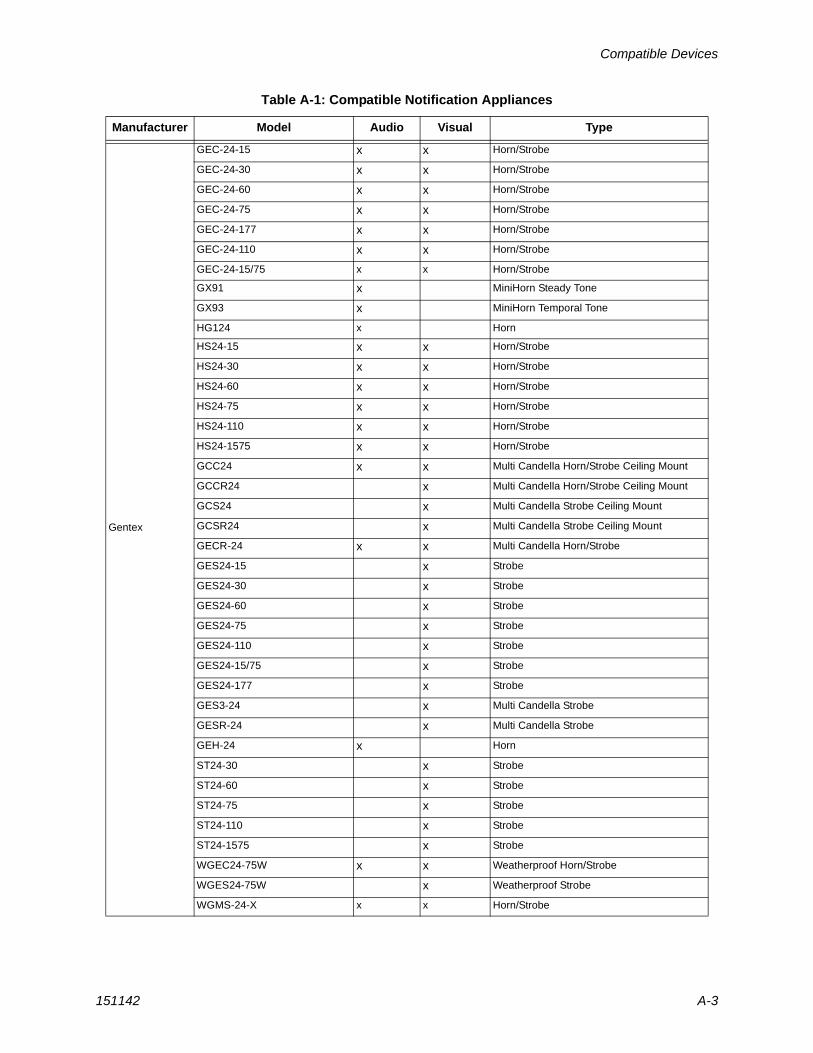
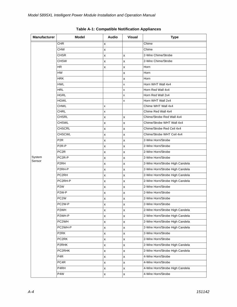
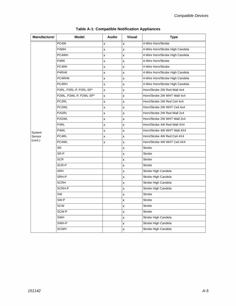
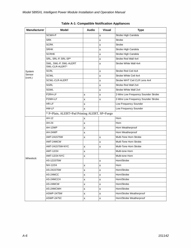
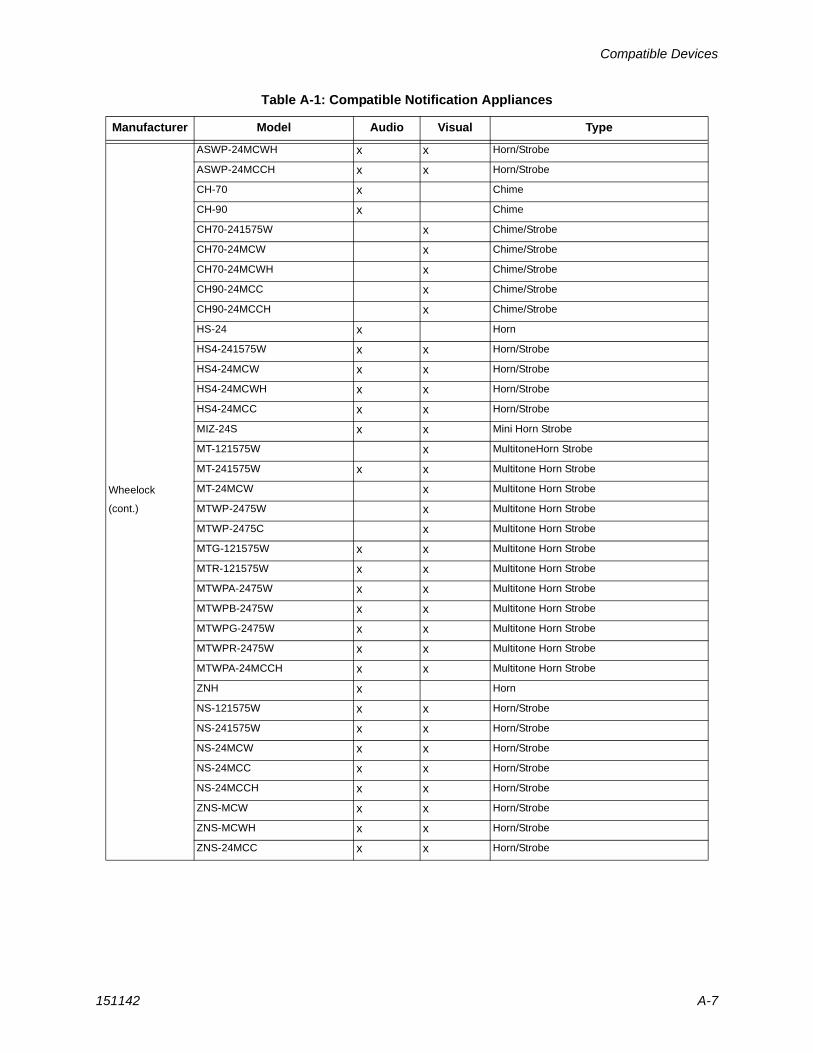
Table A-1: Compatible Notification Appliances
Manufacturer Model Audio Visual Type
AMSECO
SH24W-153075 x x Horn/Strobe
SAD24-153075 x Strobe
SAD24-75110 x Strobe
SL24W-75110 x Strobe
SL24C-3075110 x Strobe
SLB24-75 x Strobe
RSD24-153075 x Strobe
RSD24-75110 x Strobe
SH24W-75110 x x Horn/Strobe
SH24W-3075110 x x Horn/Strobe
SHB24-75 x x Horn/Strobe
SCM24W-153075 x Chimes/Strobe
SCM24W-75110 x Chimes/Strobe
SCM24C-3075110 x Chimes/Strobe
SCM24C-177 x Chimes/Strobe
H24W x Horn
H24R x Horn
Model 5895XL Intelligent Power Module Installation and Operation Manual
A-2 151142
FCI
S2415-FC x Strobe
S241575-FC x Strobe
S2430-FC x Strobe
130-3117C x Mini Horn
130-3147C x Mini Horn
BLV-6 x Vibrating Bell
BLV-10 x Vibrating Bell
BLVCH x Vibrating Chime
H12/24-FC x Horn
H12/24W-FC x Horn
H12/24K-FC x Horn
HC12/24-FC x Horn
HC12/24W-FC x Horn
HC12/24K-FC x Horn
P2415-FC x x Horn/Strobe
P2415W-FC x x Horn/Strobe
P2415K-FC x x Horn/Strobe
P241575-FC x x Horn/Strobe
P241575W-FC x x Horn/Strobe
P241575F-FC x x Horn/Strobe
P241575K-FC x x Horn/Strobe
P2430-FC x x Horn/Strobe
P2430W-FC x x Horn/Strobe
P2430K-FC x x Horn/Strobe
P2475-FC x x Horn/Strobe
P2475W-FC x x Horn/Strobe
P2475K-FC x x Horn/Strobe
P24110-FC x x Horn/Strobe
P24110W-FC x x Horn/Strobe
P24110K-FC x x Horn/Strobe
S2430W-FC x Strobe
S2430K-FC x Strobe
S2475-FC x Strobe
S2475W-FC x Strobe
S2475K-FC x Strobe
S24110-FC x Strobe
S24110W-FC x Strobe
S24110K-FC x Strobe
Federal Signal
450 x Horn
VALS x x Horn/Strobe
Table A-1: Compatible Notification Appliances
Manufacturer Model Audio Visual Type
Compatible Devices
151142 A-3
Gentex
GEC-24-15 x x Horn/Strobe
GEC-24-30 x x Horn/Strobe
GEC-24-60 x x Horn/Strobe
GEC-24-75 x x Horn/Strobe
GEC-24-177 x x Horn/Strobe
GEC-24-110 x x Horn/Strobe
GEC-24-15/75 x x Horn/Strobe
GX91 x MiniHorn Steady Tone
GX93 x MiniHorn Temporal Tone
HG124 x Horn
HS24-15 x x Horn/Strobe
HS24-30 x x Horn/Strobe
HS24-60 x x Horn/Strobe
HS24-75 x x Horn/Strobe
HS24-110 x x Horn/Strobe
HS24-1575 x x Horn/Strobe
GCC24 x x Multi Candella Horn/Strobe Ceiling Mount
GCCR24 x Multi Candella Horn/Strobe Ceiling Mount
GCS24 x Multi Candella Strobe Ceiling Mount
GCSR24 x Multi Candella Strobe Ceiling Mount
GECR-24 x x Multi Candella Horn/Strobe
GES24-15 x Strobe
GES24-30 x Strobe
GES24-60 x Strobe
GES24-75 x Strobe
GES24-110 x Strobe
GES24-15/75 x Strobe
GES24-177 x Strobe
GES3-24 x Multi Candella Strobe
GESR-24 x Multi Candella Strobe
GEH-24 x Horn
ST24-30 x Strobe
ST24-60 x Strobe
ST24-75 x Strobe
ST24-110 x Strobe
ST24-1575 x Strobe
WGEC24-75W x x Weatherproof Horn/Strobe
WGES24-75W x Weatherproof Strobe
WGMS-24-X x x Horn/Strobe
Table A-1: Compatible Notification Appliances
Manufacturer Model Audio Visual Type
Model 5895XL Intelligent Power Module Installation and Operation Manual
A-4 151142
System Sensor
CHR x Chime
CHW x Chime
CHSR x x 2-Wire Chime/Strobe
CHSW x x 2-Wire Chime/Strobe
HR x x Horn
HW x Horn
HRK x Horn
HWL x Horn WHT Wall 4x4
HRL x Horn Red Wall 4x4
HGRL x Horn Red Wall 2x4
HGWL x Horn WHT Wall 2x4
CHWL x Chime WHT Wall 4x4
CHRL x Chime Red Wall 4x4
CHSRL x x Chime/Strobe Red Wall 4x4
CHSWL x x Chime/Strobe WHT Wall 4x4
CHSCRL x x Chime/Strobe Red Ceil 4x4
CHSCWL x x Chime/Strobe WHT Ceil 4x4
P2R x x 2-Wire Horn/Strobe
P2R-P x x 2-Wire Horn/Strobe
PC2R x x 2-Wire Horn/Strobe
PC2R-P x x 2-Wire Horn/Strobe
P2RH x x 2-Wire Horn/Strobe High Candela
P2RH-P x x 2-Wire Horn/Strobe High Candela
PC2RH x x 2-Wire Horn/Strobe High Candela
PC2RH-P x x 2-Wire Horn/Strobe High Candela
P2W x x 2-Wire Horn/Strobe
P2W-P x x 2-Wire Horn/Strobe
PC2W x x 2-Wire Horn/Strobe
PC2W-P x x 2-Wire Horn/Strobe
P2WH x x 2-Wire Horn/Strobe High Candela
P2WH-P x x 2-Wire Horn/Strobe High Candela
PC2WH x x 2-Wire Horn/Strobe High Candela
PC2WH-P x x 2-Wire Horn/Strobe High Candela
P2RK x x 2-Wire Horn/Strobe
PC2RK x x 2-Wire Horn/Strobe
P2RHK x x 2-Wire Horn/Strobe High Candela
PC2RHK x x 2-Wire Horn/Strobe High Candela
P4R x x 4-Wire Horn/Strobe
PC4R x x 4-Wire Horn/Strobe
P4RH x x 4-Wire Horn/Strobe High Candela
P4W x x 4-Wire Horn/Strobe
Table A-1: Compatible Notification Appliances
Manufacturer Model Audio Visual Type
Compatible Devices
151142 A-5
System Sensor(cont.)
PC4W x x 4-Wire Horn/Strobe
P4WH x x 4-Wire Horn/Strobe High Candela
PC4WH x x 4-Wire Horn/Strobe High Candela
P4RK x x 4-Wire Horn/Strobe
PC4RK x x 4-Wire Horn/Strobe
P4RHK x x 4-Wire Horn/Strobe High Candela
PC4RHK x x 4-Wire Horn/Strobe High Candela
PC4RH x x 4-Wire Horn/Strobe High Candela
P2RL, P2RL-P, P2RL-SP* x x Horn/Strobe 2W Red Wall 4x4
P2WL, P2WL-P, P2WL-SP* x x Horn/Strobe 2W WHT Wall 4x4
PC2RL x x Horn/Strobe 2W Red Ceil 4x4
PC2WL x x Horn/Strobe 2W WHT Ceil 4x4
P2GRL x x Horn/Strobe 2W Red Wall 2x4
P2GWL x x Horn/Strobe 2W WHT Wall 2x4
P4RL x x Horn/Strobe 4W Red Wall 4X4
P4WL x x Horn/Strobe 4W WHT Wall 4X4
PC4RL x x Horn/Strobe 4W Red Ceil 4X4
PC4WL x x Horn/Strobe 4W WHT Ceil 4X4
SR x Strobe
SR-P x Strobe
SCR x Strobe
SCR-P x Strobe
SRH x Strobe High Candela
SRH-P x Strobe High Candela
SCRH x Strobe High Candela
SCRH-P x Strobe High Candela
SW x Strobe
SW-P x Strobe
SCW x Strobe
SCW-P x Strobe
SWH x Strobe High Candela
SWH-P x Strobe High Candela
SCWH x Strobe High Candela
Table A-1: Compatible Notification Appliances
Manufacturer Model Audio Visual Type
Model 5895XL Intelligent Power Module Installation and Operation Manual
A-6 151142
System Sensor(cont.)
SCWH-P x Strobe High Candela
SRK x Strobe
SCRK x Strobe
SRHK x Strobe High Candela
SCRHK x Strobe High Candela
SRL, SRL-P, SRL-SP* x Strobe Red Wall 4x4
SWL, SWL-P, SWL-ALERTSWL-CLR-ALERT*
x Strobe White Wall 4x4
SCRL x Strobe Red Ceil 4x4
SCWL x Strobe White Ceil 4x4
SCWL-CLR-ALERT x Strobe WHT Ceil CLR Lens 4x4
SGRL x Strobe Red Wall 2x4
SGWL x Strobe White Wall 2x4
P2RH-LF x x 2-Wire Low Frequency Sounder Strobe
P2WH-LF x x 2-Wire Low Frequency Sounder Strobe
HR-LF x Low Frequency Sounder
HW-LF x Low Frequency Sounder
* P=Plain, ALERT=Pad Printing ALERT, SP=Fuego
Wheelock
AH-12 x Horn
AH-24 x Horn
AH-12WP x Horn Weatherproof
AH-24WP x Horn Weatherproof
AMT-241575W x x Multi-Tone Horn Strobe
AMT-24MCW x Mutli-Tone Horn Strobe
AMT-241575W-NYC x x Multi-Tone Horn Strobe
AMT-12/24 x Multi-tone Horn
AMT-12/24 NYC x Multi-tone Horn
AS-121575W x Horn/Strobe
NH-12/24 x x Horn
AS-241575W x x Horn/Strobe
AS-24MCC x x Horn/Strobe
AS-24MCCH x x Horn/Strobe
AS-24MCW x x Horn/Strobe
AS-24MCWH x x Horn/Strobe
ASWP-2475W x x Horn/Strobe Weatherproof
ASWP-2475C x x Horn/Strobe Weatherproof
Table A-1: Compatible Notification Appliances
Manufacturer Model Audio Visual Type
Compatible Devices
151142 A-7
Wheelock
(cont.)
ASWP-24MCWH x x Horn/Strobe
ASWP-24MCCH x x Horn/Strobe
CH-70 x Chime
CH-90 x Chime
CH70-241575W x Chime/Strobe
CH70-24MCW x Chime/Strobe
CH70-24MCWH x Chime/Strobe
CH90-24MCC x Chime/Strobe
CH90-24MCCH x Chime/Strobe
HS-24 x Horn
HS4-241575W x x Horn/Strobe
HS4-24MCW x x Horn/Strobe
HS4-24MCWH x x Horn/Strobe
HS4-24MCC x x Horn/Strobe
MIZ-24S x x Mini Horn Strobe
MT-121575W x MultitoneHorn Strobe
MT-241575W x x Multitone Horn Strobe
MT-24MCW x Multitone Horn Strobe
MTWP-2475W x Multitone Horn Strobe
MTWP-2475C x Multitone Horn Strobe
MTG-121575W x x Multitone Horn Strobe
MTR-121575W x x Multitone Horn Strobe
MTWPA-2475W x x Multitone Horn Strobe
MTWPB-2475W x x Multitone Horn Strobe
MTWPG-2475W x x Multitone Horn Strobe
MTWPR-2475W x x Multitone Horn Strobe
MTWPA-24MCCH x x Multitone Horn Strobe
ZNH x Horn
NS-121575W x x Horn/Strobe
NS-241575W x x Horn/Strobe
NS-24MCW x x Horn/Strobe
NS-24MCC x x Horn/Strobe
NS-24MCCH x x Horn/Strobe
ZNS-MCW x x Horn/Strobe
ZNS-MCWH x x Horn/Strobe
ZNS-24MCC x x Horn/Strobe
Table A-1: Compatible Notification Appliances
Manufacturer Model Audio Visual Type
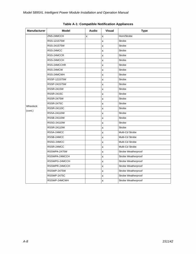
Model 5895XL Intelligent Power Module Installation and Operation Manual
A-8 151142
Wheelock
(cont.)
ZNS-24MCCH x x Horn/Strobe
RSS-121575W x Strobe
RSS-241575W x Strobe
RSS-24MCC x Strobe
RSS-24MCCR x Strobe
RSS-24MCCH x Strobe
RSS-24MCCHR x Strobe
RSS-24MCW x Strobe
RSS-24MCWH x Strobe
RSSP-121575W x Strobe
RSSP-241575W x Strobe
RSSR-2415W x Strobe
RSSR-2415C x Strobe
RSSR-2475W x Strobe
RSSR-2475C x Strobe
RSSR-24110C x Strobe
RSSA-24110W x Strobe
RSSB-24110W x Strobe
RSSG-24110W x Strobe
RSSR-24110W x Strobe
RSSA-24MCC x Multi-Cd Strobe
RSSB-24MCC x Multi-Cd Strobe
RSSG-24MCC x Multi-Cd Strobe
RSSR-24MCC x Multi-Cd Strobe
RSSWPA-2475W x Strobe Weatherproof
RSSWPA-24MCCH x Strobe Weatherproof
RSSWPG-24MCCH x Strobe Weatherproof
RSSWPR-24MCCH x Strobe Weatherproof
RSSWP-2475W x Strobe Weatherproof
RSSWP-2475C x Strobe Weatherproof
RSSWP-24MCWH x Strobe Weatherproof
Table A-1: Compatible Notification Appliances
Manufacturer Model Audio Visual Type
Compatible Devices
151142 A-9
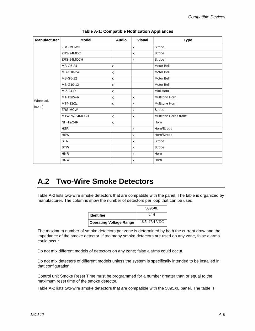
A.2 Two-Wire Smoke Detectors
Table A-2 lists two-wire smoke detectors that are compatible with the panel. The table is organized by manufacturer. The columns show the number of detectors per loop that can be used.
The maximum number of smoke detectors per zone is determined by both the current draw and the impedance of the smoke detector. If too many smoke detectors are used on any zone, false alarms could occur.
Do not mix different models of detectors on any zone; false alarms could occur.
Do not mix detectors of different models unless the system is specifically intended to be installed in that configuration.
Control unit Smoke Reset Time must be programmed for a number greater than or equal to the maximum reset time of the smoke detector.
Table A-2 lists two-wire smoke detectors that are compatible with the 5895XL panel. The table is
Wheelock
(cont.)
ZRS-MCWH x Strobe
ZRS-24MCC x Strobe
ZRS-24MCCH x Strobe
MB-G6-24 x Motor Bell
MB-G10-24 x Motor Bell
MB-G6-12 x Motor Bell
MB-G10-12 x Motor Bell
MIZ-24-R x Mini-Horn
MT-12/24-R x x Multitone Horn
MT4-12/2z x x Multitone Horn
ZRS-MCW x Strobe
MTWPR-24MCCH x x Multitone Horn Strobe
NH-12/24R x Horn
HSR x Horn/Strobe
HSW x Horn/Strobe
STR x Strobe
STW x Strobe
HNR x Horn
HNW x Horn
5895XL
Identifier 24H
Operating Voltage Range 18.5–27.4 VDC
Table A-1: Compatible Notification Appliances
Manufacturer Model Audio Visual Type
Model 5895XL Intelligent Power Module Installation and Operation Manual
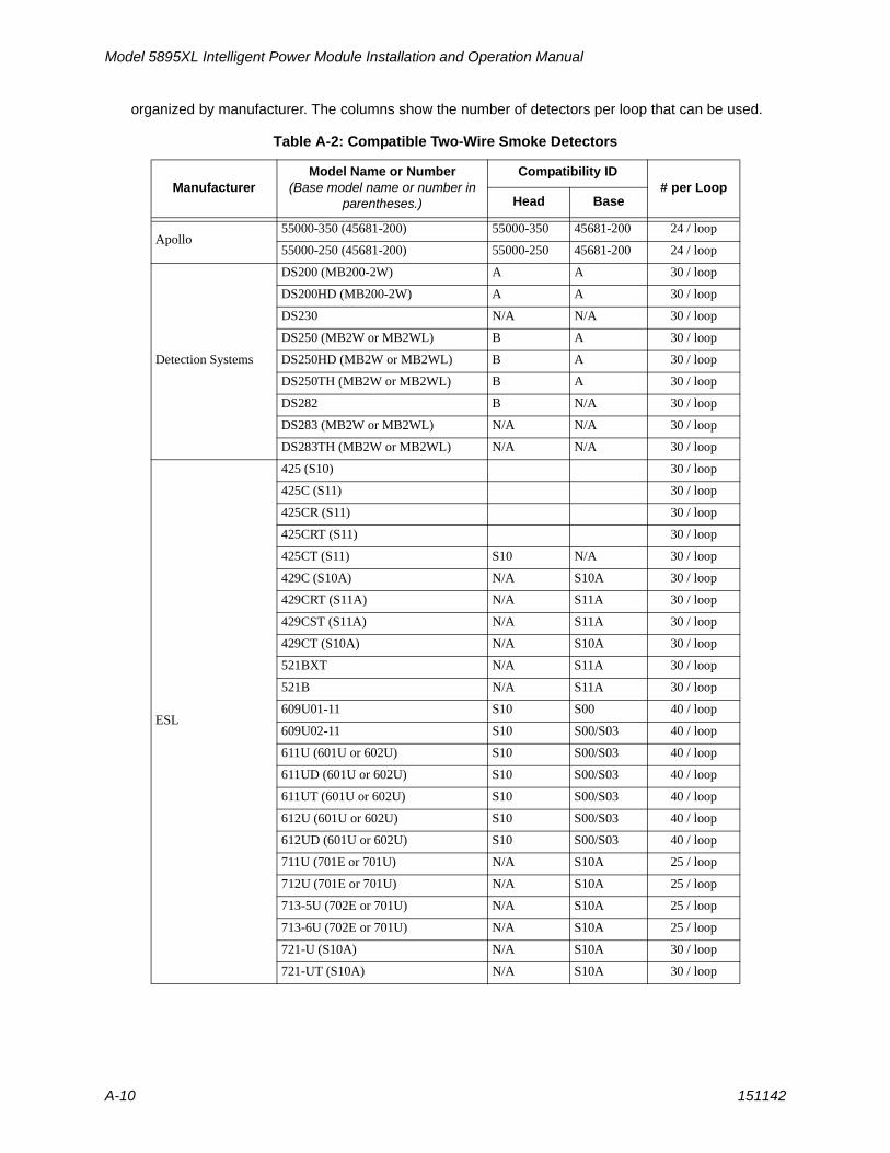
A-10 151142
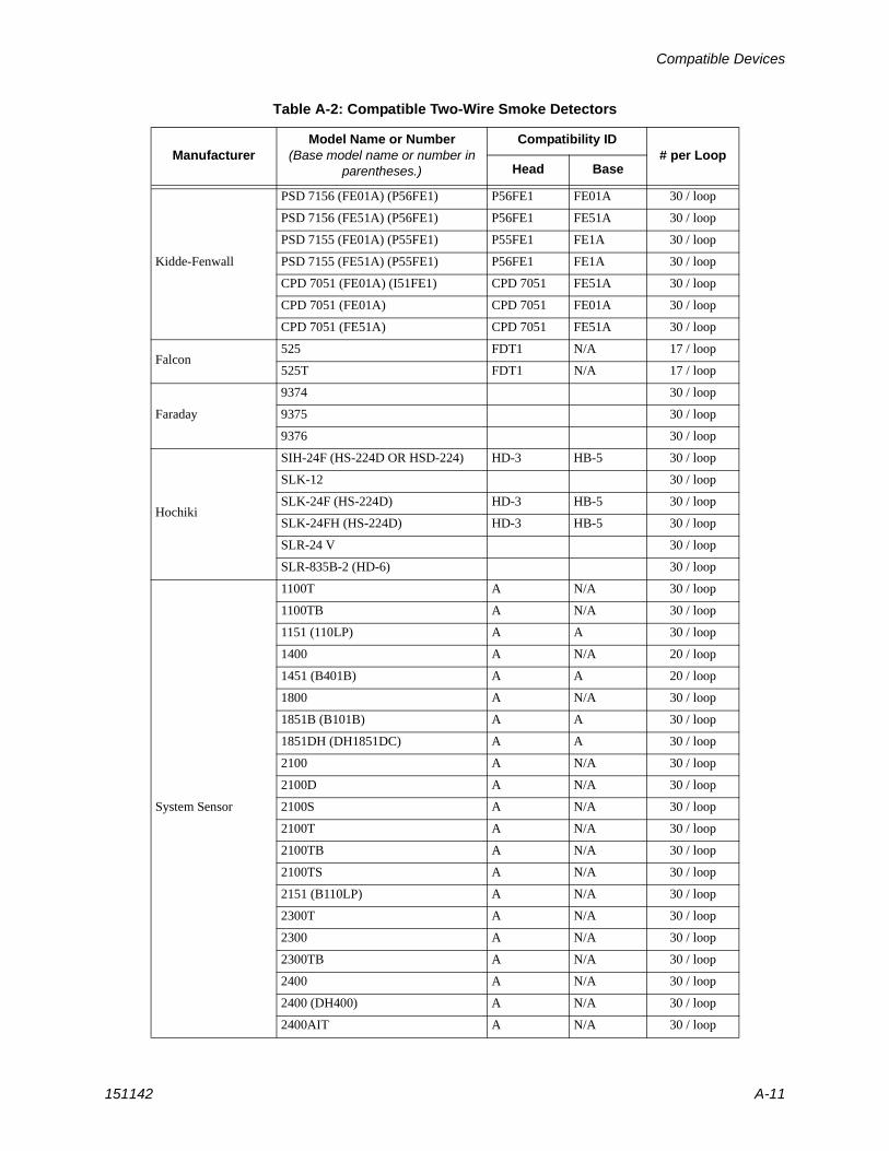
organized by manufacturer. The columns show the number of detectors per loop that can be used.
Table A-2: Compatible Two-Wire Smoke Detectors
ManufacturerModel Name or Number
(Base model name or number in parentheses.)
Compatibility ID# per Loop
Head Base
Apollo55000-350 (45681-200) 55000-350 45681-200 24 / loop
55000-250 (45681-200) 55000-250 45681-200 24 / loop
Detection Systems
DS200 (MB200-2W) A A 30 / loop
DS200HD (MB200-2W) A A 30 / loop
DS230 N/A N/A 30 / loop
DS250 (MB2W or MB2WL) B A 30 / loop
DS250HD (MB2W or MB2WL) B A 30 / loop
DS250TH (MB2W or MB2WL) B A 30 / loop
DS282 B N/A 30 / loop
DS283 (MB2W or MB2WL) N/A N/A 30 / loop
DS283TH (MB2W or MB2WL) N/A N/A 30 / loop
ESL
425 (S10) 30 / loop
425C (S11) 30 / loop
425CR (S11) 30 / loop
425CRT (S11) 30 / loop
425CT (S11) S10 N/A 30 / loop
429C (S10A) N/A S10A 30 / loop
429CRT (S11A) N/A S11A 30 / loop
429CST (S11A) N/A S11A 30 / loop
429CT (S10A) N/A S10A 30 / loop
521BXT N/A S11A 30 / loop
521B N/A S11A 30 / loop
609U01-11 S10 S00 40 / loop
609U02-11 S10 S00/S03 40 / loop
611U (601U or 602U) S10 S00/S03 40 / loop
611UD (601U or 602U) S10 S00/S03 40 / loop
611UT (601U or 602U) S10 S00/S03 40 / loop
612U (601U or 602U) S10 S00/S03 40 / loop
612UD (601U or 602U) S10 S00/S03 40 / loop
711U (701E or 701U) N/A S10A 25 / loop
712U (701E or 701U) N/A S10A 25 / loop
713-5U (702E or 701U) N/A S10A 25 / loop
713-6U (702E or 701U) N/A S10A 25 / loop
721-U (S10A) N/A S10A 30 / loop
721-UT (S10A) N/A S10A 30 / loop
Compatible Devices
151142 A-11
Kidde-Fenwall
PSD 7156 (FE01A) (P56FE1) P56FE1 FE01A 30 / loop
PSD 7156 (FE51A) (P56FE1) P56FE1 FE51A 30 / loop
PSD 7155 (FE01A) (P55FE1) P55FE1 FE1A 30 / loop
PSD 7155 (FE51A) (P55FE1) P56FE1 FE1A 30 / loop
CPD 7051 (FE01A) (I51FE1) CPD 7051 FE51A 30 / loop
CPD 7051 (FE01A) CPD 7051 FE01A 30 / loop
CPD 7051 (FE51A) CPD 7051 FE51A 30 / loop
Falcon525 FDT1 N/A 17 / loop
525T FDT1 N/A 17 / loop
Faraday
9374 30 / loop
9375 30 / loop
9376 30 / loop
Hochiki
SIH-24F (HS-224D OR HSD-224) HD-3 HB-5 30 / loop
SLK-12 30 / loop
SLK-24F (HS-224D) HD-3 HB-5 30 / loop
SLK-24FH (HS-224D) HD-3 HB-5 30 / loop
SLR-24 V 30 / loop
SLR-835B-2 (HD-6) 30 / loop
System Sensor
1100T A N/A 30 / loop
1100TB A N/A 30 / loop
1151 (110LP) A A 30 / loop
1400 A N/A 20 / loop
1451 (B401B) A A 20 / loop
1800 A N/A 30 / loop
1851B (B101B) A A 30 / loop
1851DH (DH1851DC) A A 30 / loop
2100 A N/A 30 / loop
2100D A N/A 30 / loop
2100S A N/A 30 / loop
2100T A N/A 30 / loop
2100TB A N/A 30 / loop
2100TS A N/A 30 / loop
2151 (B110LP) A N/A 30 / loop
2300T A N/A 30 / loop
2300 A N/A 30 / loop
2300TB A N/A 30 / loop
2400 A N/A 30 / loop
2400 (DH400) A N/A 30 / loop
2400AIT A N/A 30 / loop
Table A-2: Compatible Two-Wire Smoke Detectors
ManufacturerModel Name or Number
(Base model name or number in parentheses.)
Compatibility ID# per Loop
Head Base
Model 5895XL Intelligent Power Module Installation and Operation Manual
A-12 151142
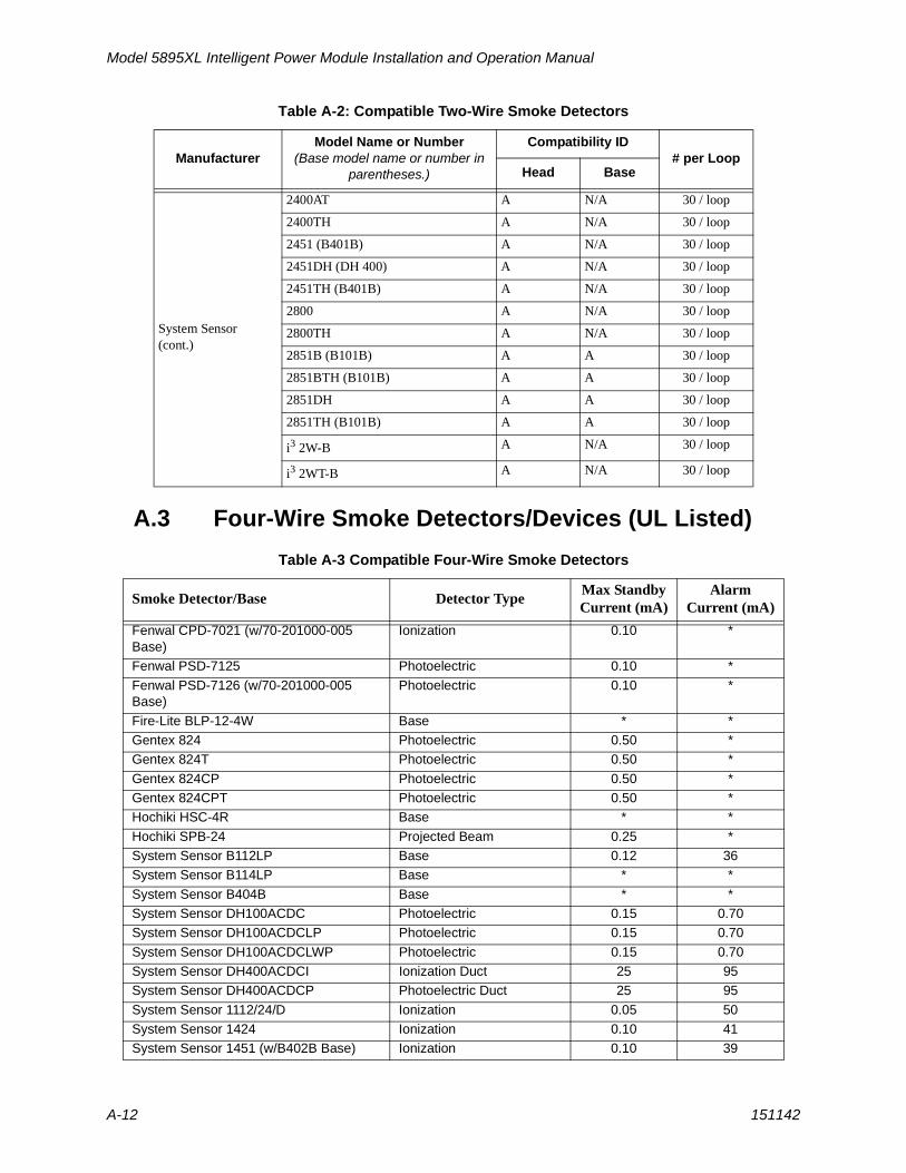
A.3 Four-Wire Smoke Detectors/Devices (UL Listed)
Table A-3 Compatible Four-Wire Smoke Detectors
System Sensor(cont.)
2400AT A N/A 30 / loop
2400TH A N/A 30 / loop
2451 (B401B) A N/A 30 / loop
2451DH (DH 400) A N/A 30 / loop
2451TH (B401B) A N/A 30 / loop
2800 A N/A 30 / loop
2800TH A N/A 30 / loop
2851B (B101B) A A 30 / loop
2851BTH (B101B) A A 30 / loop
2851DH A A 30 / loop
2851TH (B101B) A A 30 / loop
i3 2W-B A N/A 30 / loop
i3 2WT-B A N/A 30 / loop
Smoke Detector/Base Detector TypeMax StandbyCurrent (mA)
Alarm Current (mA)
Fenwal CPD-7021 (w/70-201000-005 Base)
Ionization 0.10 *
Fenwal PSD-7125 Photoelectric 0.10 *
Fenwal PSD-7126 (w/70-201000-005 Base)
Photoelectric 0.10 *
Fire-Lite BLP-12-4W Base * *Gentex 824 Photoelectric 0.50 *Gentex 824T Photoelectric 0.50 *
Gentex 824CP Photoelectric 0.50 *Gentex 824CPT Photoelectric 0.50 *Hochiki HSC-4R Base * *
Hochiki SPB-24 Projected Beam 0.25 *System Sensor B112LP Base 0.12 36System Sensor B114LP Base * *
System Sensor B404B Base * *System Sensor DH100ACDC Photoelectric 0.15 0.70System Sensor DH100ACDCLP Photoelectric 0.15 0.70
System Sensor DH100ACDCLWP Photoelectric 0.15 0.70System Sensor DH400ACDCI Ionization Duct 25 95System Sensor DH400ACDCP Photoelectric Duct 25 95
System Sensor 1112/24/D Ionization 0.05 50System Sensor 1424 Ionization 0.10 41System Sensor 1451 (w/B402B Base) Ionization 0.10 39
Table A-2: Compatible Two-Wire Smoke Detectors
ManufacturerModel Name or Number
(Base model name or number in parentheses.)
Compatibility ID# per Loop
Head Base
Compatible Devices
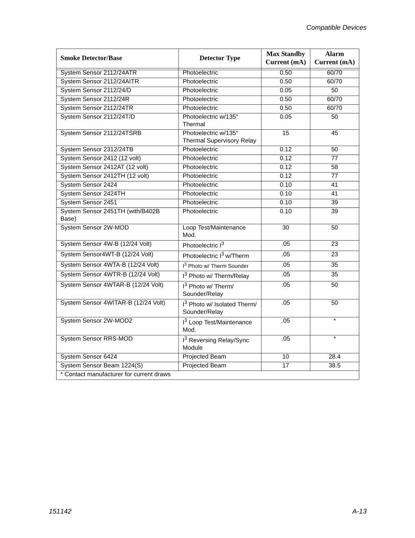
151142 A-13
System Sensor 2112/24ATR Photoelectric 0.50 60/70System Sensor 2112/24AITR Photoelectric 0.50 60/70System Sensor 2112/24/D Photoelectric 0.05 50
System Sensor 2112/24R Photoelectric 0.50 60/70System Sensor 2112/24TR Photoelectric 0.50 60/70System Sensor 2112/24T/D Photoelectric w/135°
Thermal0.05 50
System Sensor 2112/24TSRB Photoelectric w/135° Thermal Supervisory Relay
15 45
System Sensor 2312/24TB Photoelectric 0.12 50
System Sensor 2412 (12 volt) Photoelectric 0.12 77System Sensor 2412AT (12 volt) Photoelectric 0.12 58System Sensor 2412TH (12 volt) Photoelectric 0.12 77
System Sensor 2424 Photoelectric 0.10 41System Sensor 2424TH Photoelectric 0.10 41System Sensor 2451 Photoelectric 0.10 39
System Sensor 2451TH (with/B402B Base)
Photoelectric 0.10 39
System Sensor 2W-MOD Loop Test/Maintenance Mod.
30 50
System Sensor 4W-B (12/24 Volt) Photoelectric I3 .05 23
System Sensor4WT-B (12/24 Volt) Photoelectric I3 w/Therm .05 23
System Sensor 4WTA-B (12/24 Volt) I3 Photo w/ Therm Sounder .05 35
System Sensor 4WTR-B (12/24 Volt) I3 Photo w/ Therm/Relay .05 35
System Sensor 4WTAR-B (12/24 Volt) I3 Photo w/ Therm/Sounder/Relay
.05 50
System Sensor 4WITAR-B (12/24 Volt) I3 Photo w/ Isolated Therm/Sounder/Relay
.05 50
System Sensor 2W-MOD2 I3 Loop Test/Maintenance Mod.
.05 *
System Sensor RRS-MOD I3 Reversing Relay/Sync Module
.05 *
System Sensor 6424 Projected Beam 10 28.4
System Sensor Beam 1224(S) Projected Beam 17 38.5* Contact manufacturer for current draws
Smoke Detector/Base Detector TypeMax StandbyCurrent (mA)
Alarm Current (mA)
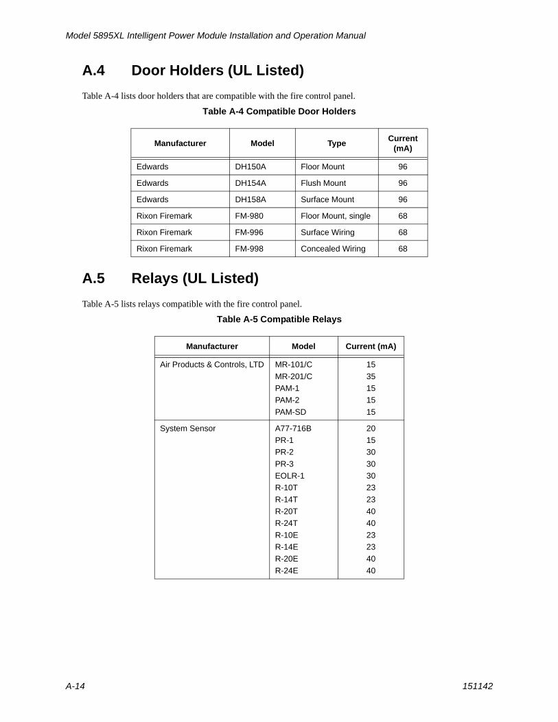
Model 5895XL Intelligent Power Module Installation and Operation Manual
A-14 151142
A.4 Door Holders (UL Listed)
Table A-4 lists door holders that are compatible with the fire control panel.
Table A-4 Compatible Door Holders
A.5 Relays (UL Listed)
Table A-5 lists relays compatible with the fire control panel.
Table A-5 Compatible Relays
Manufacturer Model TypeCurrent
(mA)
Edwards DH150A Floor Mount 96
Edwards DH154A Flush Mount 96
Edwards DH158A Surface Mount 96
Rixon Firemark FM-980 Floor Mount, single 68
Rixon Firemark FM-996 Surface Wiring 68
Rixon Firemark FM-998 Concealed Wiring 68
Manufacturer Model Current (mA)
Air Products & Controls, LTD MR-101/C
MR-201/CPAM-1PAM-2
PAM-SD
15
351515
15
System Sensor A77-716BPR-1PR-2
PR-3EOLR-1R-10T
R-14TR-20TR-24T
R-10ER-14ER-20E
R-24E
201530
303023
234040
232340
40
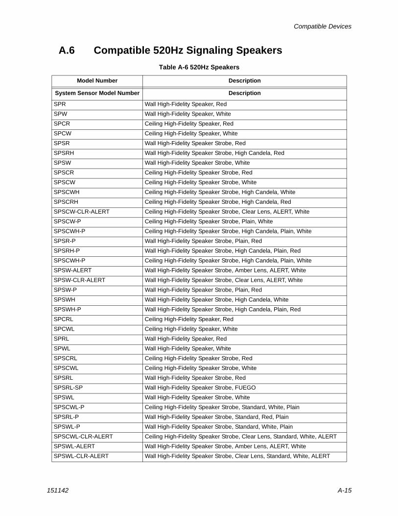
Compatible Devices
151142 A-15
A.6 Compatible 520Hz Signaling Speakers
Table A-6 520Hz Speakers
Model Number Description
System Sensor Model Number Description
SPR Wall High-Fidelity Speaker, Red
SPW Wall High-Fidelity Speaker, White
SPCR Ceiling High-Fidelity Speaker, Red
SPCW Ceiling High-Fidelity Speaker, White
SPSR Wall High-Fidelity Speaker Strobe, Red
SPSRH Wall High-Fidelity Speaker Strobe, High Candela, Red
SPSW Wall High-Fidelity Speaker Strobe, White
SPSCR Ceiling High-Fidelity Speaker Strobe, Red
SPSCW Ceiling High-Fidelity Speaker Strobe, White
SPSCWH Ceiling High-Fidelity Speaker Strobe, High Candela, White
SPSCRH Ceiling High-Fidelity Speaker Strobe, High Candela, Red
SPSCW-CLR-ALERT Ceiling High-Fidelity Speaker Strobe, Clear Lens, ALERT, White
SPSCW-P Ceiling High-Fidelity Speaker Strobe, Plain, White
SPSCWH-P Ceiling High-Fidelity Speaker Strobe, High Candela, Plain, White
SPSR-P Wall High-Fidelity Speaker Strobe, Plain, Red
SPSRH-P Wall High-Fidelity Speaker Strobe, High Candela, Plain, Red
SPSCWH-P Ceiling High-Fidelity Speaker Strobe, High Candela, Plain, White
SPSW-ALERT Wall High-Fidelity Speaker Strobe, Amber Lens, ALERT, White
SPSW-CLR-ALERT Wall High-Fidelity Speaker Strobe, Clear Lens, ALERT, White
SPSW-P Wall High-Fidelity Speaker Strobe, Plain, Red
SPSWH Wall High-Fidelity Speaker Strobe, High Candela, White
SPSWH-P Wall High-Fidelity Speaker Strobe, High Candela, Plain, Red
SPCRL Ceiling High-Fidelity Speaker, Red
SPCWL Ceiling High-Fidelity Speaker, White
SPRL Wall High-Fidelity Speaker, Red
SPWL Wall High-Fidelity Speaker, White
SPSCRL Ceiling High-Fidelity Speaker Strobe, Red
SPSCWL Ceiling High-Fidelity Speaker Strobe, White
SPSRL Wall High-Fidelity Speaker Strobe, Red
SPSRL-SP Wall High-Fidelity Speaker Strobe, FUEGO
SPSWL Wall High-Fidelity Speaker Strobe, White
SPSCWL-P Ceiling High-Fidelity Speaker Strobe, Standard, White, Plain
SPSRL-P Wall High-Fidelity Speaker Strobe, Standard, Red, Plain
SPSWL-P Wall High-Fidelity Speaker Strobe, Standard, White, Plain
SPSCWL-CLR-ALERT Ceiling High-Fidelity Speaker Strobe, Clear Lens, Standard, White, ALERT
SPSWL-ALERT Wall High-Fidelity Speaker Strobe, Amber Lens, ALERT, White
SPSWL-CLR-ALERT Wall High-Fidelity Speaker Strobe, Clear Lens, Standard, White, ALERT
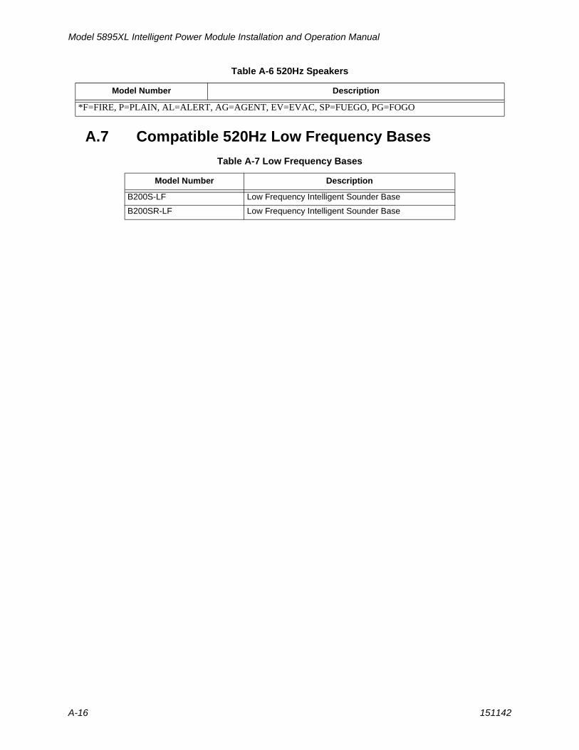
Model 5895XL Intelligent Power Module Installation and Operation Manual
A-16 151142
A.7 Compatible 520Hz Low Frequency Bases
*F=FIRE, P=PLAIN, AL=ALERT, AG=AGENT, EV=EVAC, SP=FUEGO, PG=FOGO
Table A-7 Low Frequency Bases
Model Number Description
B200S-LF Low Frequency Intelligent Sounder Base
B200SR-LF Low Frequency Intelligent Sounder Base
Table A-6 520Hz Speakers
Model Number Description
Honeywell Fire Product Warranty and Return Policy
General Terms and Conditions• All new fire products manufactured by Honeywell Silent Knight have a limited warranty period of 36
months from the date of manufacture against defects in materials and workmanship. See limited warranty statement for details.
• This limited warranty does not apply to those products that are damaged due to misuse, abuse, negligence, exposure to adverse environmental conditions, or have been modified in any manner whatsoever.
Repair and RMA Procedure• All products that are returned to Honeywell for credit or repair require a RMA (Return Authorization)
number. Call Customer Service at 800-328-0103 or 203-484-7161 between 8:00 A.M. and 5:00 P.M. EST, Monday through Friday to obtain a return authorization number.
• Honeywell Silent Knight and Farenhyt Series Technical Support is available at 800-446-6444 between 8:00 A.M. and 5:00 P.M. CST, Monday through Friday.
• All returns for credit are subject to inspection and testing at the factory before actual determination is made to allow credit.
• RMA number must be prominently displayed on the outside of the shipping box. See return address example under Advanced Replacement Policy.
• Included with each return should be: a packing slip that has the RMA number, a content list, and a detailed description of the problem.
• All products returned by Honeywell must be sent freight pre-paid. After the product is processed, Honeywell will pay for shipping product back to customer via UPS ground.
• Return the Honeywell Silent Knight product circuit board only. Products that are returned in cabinets will be charged an additional $50 to cover the extra shipping and handling costs over board only returns. Do not return batteries. Honeywell has the authority to determine if a product is repairable. Products that are deemed un-repairable will be returned to the customer.
• Product that is returned that has a board date code more than 36 months from date of manufacture will be repaired and the customer will be assessed the standard Honeywell Silent Knight repair charge for that model.
Advanced Replacement Policy• Honeywell Silent Knight and Farenhyt Series offers an option of advance replacement for fire product
printed circuit boards that fail during the first 6 months of the warranty period. These items must be returned with transportation charges prepaid and must be accompanied by a return authorization.
• For advance replacement of a defective board, contact your local Honeywell Silent Knight distributor or call Honeywell Silent Knight at 800-328-0103 to obtain a RMA (Return Authorization) number and request advanced replacement.
• A new or refurbished board will be shipped to the customer. The customer will initially be billed for the replacement board but a credit will be issued after the repairable board is received at Honeywell Silent Knight. All returned products must comply with the guidelines described under “General Terms and Conditions” and “Repair and RMA Procedure”.
• The defective board must be returned within 30 days of shipment of replacement board for customer to receive credit. No credit will be issued if the returned board was damaged due to misuse or abuse.

• Repairs and returns should be sent to:Honeywell Fire SystemsAttn: Repair Department / RA Number_______________________12 Clintonville RoadNorthford, CT 06472 USA
Manufacturer Warranties and Limitation of Liability
Manufacturer Warranties. Subject to the limitations set forth herein, Manufacturer warrants that the Products manufactured by it in its Northford, Connecticut facility and sold by it to its authorized Distributors shall be free, under normal use and service, from defects in material and workmanship for a period of thirty six months (36) months from the date of manufacture (effective Jan. 1, 2009). The Products manufactured and sold by Manufacturer are date stamped at the time of production. Manufacturer does not warrant Products that are not manufactured by it in its Northford, Connecticut facility but assigns to its Distributor, to extent possible, any warranty offered by the manufacturer of such product. This warranty shall be void if a Product is altered, service repaired by anyone other than Manufacturer or its authorized Distributors. This warranty shall also be void if there is a failure to maintain the Products and the systems in which they operate in proper working conditions.
MANUFACTURER MAKES NO FURTHER WARRANTIES, AND DISCLAIMS ANY AND ALL OTHER WARRANTIES, EITHER EXPRESSED OR IMPLIED, WITH RESPECT TO THE PRODUCTS,TRADEMARKS, PROGRAMS AND SERVICES RENDERED BY MANUFACTURER INCLUDING WITHOUT LIMITATION, INFRINGEMENT, TITLE, MERCHANTABILITY, OR FITNESS FOR ANY PARTICULAR PURPOSE. MANUFACTURER SHALL NOT BE LIABLE FOR ANY PERSONAL INJURY OR DEATH WHICH MAY ARISE IN THE COURSE OF, OR AS A RESULT OF, PERSONAL, COMMERCIAL OR INDUSTRIAL USES OF ITS PRODUCTS.
This document constitutes the only warranty made by Manufacturer with respect to its products and replaces all previous warranties and is the only warranty made by Manufacturer. No increase or alteration, written or verbal, of the obligation of this warranty is authorized. Manufacturer does not represent that its products will prevent any loss by fire or otherwise.
Warranty Claims. Manufacturer shall replace or repair, at Manufacturer's discretion, each part returned by its authorized Distributor and acknowledged by Manufacturer to be defective, provided that such part shall have been returned to Manufacturer with all charges prepaid and the authorized Distributor has completed Manufacturer's Return Material Authorization form. The replacement part shall come from Manufacturer's stock and may be new or refurbished. THE FOREGOING IS DISTRIBUTOR'S SOLE AND EXCLUSIVE REMEDY IN THE EVENT OF A WARRANTY CLAIM.
Warn-HL-08-2009.fm


Silent Knight12 Clintonville Road
Northford, CT 06472-1610203-484-7161
Fax: 203-484-7118
www.silentknight.com