Embed Size (px)
Citation preview
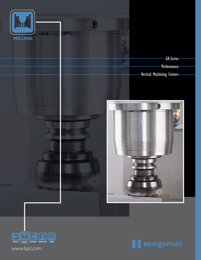
MILLING
www.bpt.com
2
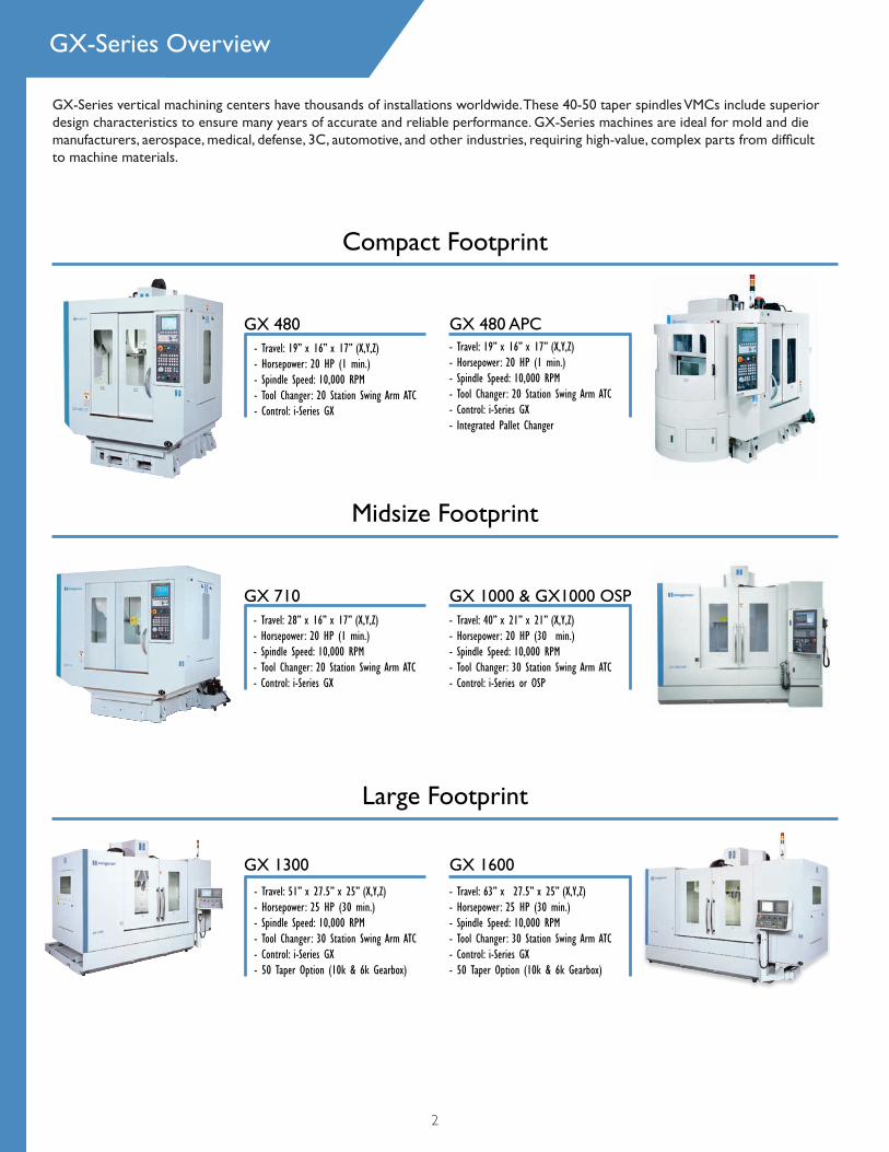
GX-Series vertical machining centers have thousands of installations worldwide. These 40-50 taper spindles VMCs include superior design characteristics to ensure many years of accurate and reliable performance. GX-Series machines are ideal for mold and die manufacturers, aerospace, medical, defense, 3C, automotive, and other industries, requiring high-value, complex parts from diffi cult to machine materials.
GX-Series Overview
- Travel: 19” x 16” x 17” (X,Y,Z)- Horsepower: 20 HP (1 min.)- Spindle Speed: 10,000 RPM- Tool Changer: 20 Station Swing Arm ATC- Control: i-Series GX
Compact Footprint
Midsize Footprint
Large Footprint
GX 710
GX 480 GX 480 APC
- Travel: 40” x 21” x 21” (X,Y,Z)- Horsepower: 20 HP (30 min.)- Spindle Speed: 10,000 RPM- Tool Changer: 30 Station Swing Arm ATC - Control: i-Series or OSP
GX 1000 & GX1000 OSP
- Travel: 51” x 27.5” x 25” (X,Y,Z)- Horsepower: 25 HP (30 min.)- Spindle Speed: 10,000 RPM- Tool Changer: 30 Station Swing Arm ATC - Control: i-Series GX- 50 Taper Option (10k & 6k Gearbox)
GX 1300
- Travel: 63” x 27.5” x 25” (X,Y,Z)- Horsepower: 25 HP (30 min.)- Spindle Speed: 10,000 RPM- Tool Changer: 30 Station Swing Arm ATC - Control: i-Series GX- 50 Taper Option (10k & 6k Gearbox)
GX 1600
- Travel: 28” x 16” x 17” (X,Y,Z)- Horsepower: 20 HP (1 min.)- Spindle Speed: 10,000 RPM- Tool Changer: 20 Station Swing Arm ATC - Control: i-Series GX
- Travel: 19” x 16” x 17” (X,Y,Z)- Horsepower: 20 HP (1 min.)- Spindle Speed: 10,000 RPM- Tool Changer: 20 Station Swing Arm ATC- Control: i-Series GX- Integrated Pallet Changer
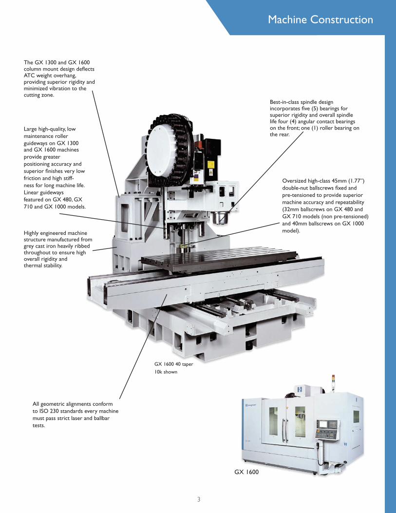
Highly engineered machine structure manufactured from grey cast iron heavily ribbed throughout to ensure high overall rigidity and thermal stability.
The GX 1300 and GX 1600 column mount design defl ects ATC weight overhang, providing superior rigidity and minimized vibration to the cutting zone.
GX 1600 40 taper
10k shown
Best-in-class spindle design incorporates fi ve (5) bearings for superior rigidity and overall spindle life four (4) angular contact bearings on the front; one (1) roller bearing on the rear.
Large high-quality, low maintenance roller guideways on GX 1300 and GX 1600 machines provide greater positioning accuracy and superior fi nishes very low friction and high stiff-ness for long machine life. Linear guideways featured on GX 480, GX 710 and GX 1000 models.
Oversized high-class 45mm (1.77”) double-nut ballscrews fi xed and pre-tensioned to provide superior machine accuracy and repeatability (32mm ballscrews on GX 480 and GX 710 models (non pre-tensioned)and 40mm ballscrews on GX 1000 model).
All geometric alignments conform to ISO 230 standards every machine must pass strict laser and ballbar tests.
3
Machine Construction
GX 1600
Key Features
4
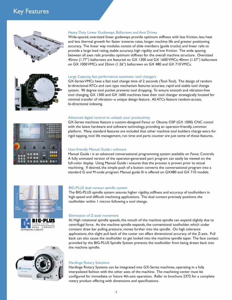
Heavy Duty Linear Guideways, Ballscrews and Axis DrivesWide-spaced, oversized linear guideways provide optimum stiffness with less friction, less heat and less thermal growth for faster traverse rates, longer machine life and greater positioningaccuracy. The linear way modules consist of slide members (guide trucks) and linear rails toprovide a large load rating, stable accuracy, high rigidity and low friction. The wide spacingbetween all axes rails provides optimum stiffness for the overall machine structure. Oversized45mm (1.77”) ballscrews are featured on GX 1300 and GX 1600 VMCs; 40mm (1.57”) ballscrewson GX 1000 VMCs and 32mm (1.26”) ballscrews on GX 480 and GX 710 VMCs.
Large Capacity, fast performance automatic tool changersGX-Series VMCs have a fast tool change time of 2 seconds (Tool-Tool). The design of randombi-directional ATCs and cam type mechanism features accurate, rapid and stable tool changesystem. 90 degree tool pocket prevents tool dropping. To ensure smooth and vibration-freetool changing, GX 1300 and GX 1600 machines have their tool changer strategically located forminimal transfer of vibration--a unique design feature. All ATCs feature random-access,bi-directional indexing.
Advanced digital control to unleash your productivityGX-Series machines feature a custom-designed Fanuc or Okuma OSP (GX 1000) CNC contol with the latest hardware and software technology, providing an operator-friendly, common platform. Many standard features are included that other machine tool builders charge extra for rigid tapping, tool life management, run time and parts counter are just some of those features.
User-friendly Manual Guide i softwareManual Guide i is an advanced conversational programming system available on Fanuc Controls. A fully animated version of the operator-generated part program can easily be viewed on the full-color display. Using Manual Guide i ensures that the process is proven prior to actual machining. If desired, the simple push of a button converts the conversational program into a standard G and M-code program. Manual guide 0i is offered on GX480 and GX 710 models.
Hardinge Rotary SolutionsHardinge Rotary Systems can be integrated into GX-Series machines, operating in a fullyinterpolated fashion with the other axes of the machine. The machining center must beconfi gured for immediate or future 4th-axis operation. Refer to brochure 2372 for a completerotary product offering with dimensions and specifi cations.
BIG-PLUS dual contact spindle systemThe BIG-PLUS spindle system assures higher rigidity, stiffness and accuracy of toolholders in high-speed and diffi cult machining applications. The dual contact precisely positions the toolholder within 1 micron following a tool change.
Elimination of Z-axial movementAt High rotational spindle speeds, the mouth of the machine spindle can expand slightly due to centrifugal force. As the machine spindle expands, the conventional toolholder, which under constant draw bar pulling pressure, moves further into the spindle. On high tolerance applications, this slight pull back of the cutter can affect dimensional accuracy of the Z-axis. Pull back can also cause the toolholder to get locked into the machine spindle taper. The face contact provided by the BIG-PLUS Spindle System prevents the toolholder from being drawn back into the machine spindle.
GX-Series Spindles
5
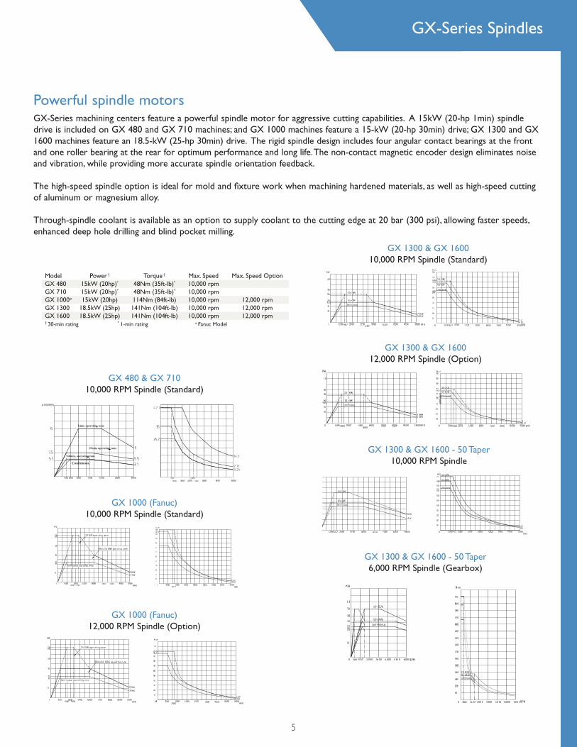
GX-Series machining centers feature a powerful spindle motor for aggressive cutting capabilities. A 15kW (20-hp 1min) spindle drive is included on GX 480 and GX 710 machines; and GX 1000 machines feature a 15-kW (20-hp 30min) drive; GX 1300 and GX 1600 machines feature an 18.5-kW (25-hp 30min) drive. The rigid spindle design includes four angular contact bearings at the front and one roller bearing at the rear for optimum performance and long life. The non-contact magnetic encoder design eliminates noise and vibration, while providing more accurate spindle orientation feedback. The high-speed spindle option is ideal for mold and fixture work when machining hardened materials, as well as high-speed cutting of aluminum or magnesium alloy.
Through-spindle coolant is available as an option to supply coolant to the cutting edge at 20 bar (300 psi), allowing faster speeds, enhanced deep hole drilling and blind pocket milling.
Powerful spindle motorsHeavy Duty Linear Guideways, Ballscrews and Axis DrivesWide-spaced, oversized linear guideways provide optimum stiffness with less friction, less heat and less thermal growth for faster traverse rates, longer machine life and greater positioningaccuracy. The linear way modules consist of slide members (guide trucks) and linear rails toprovide a large load rating, stable accuracy, high rigidity and low friction. The wide spacingbetween all axes rails provides optimum stiffness for the overall machine structure. Oversized45mm (1.77”) ballscrews are featured on GX 1300 and GX 1600 VMCs; 40mm (1.57”) ballscrewson GX 1000 VMCs and 32mm (1.26”) ballscrews on GX 480 and GX 710 VMCs.
Large Capacity, fast performance automatic tool changersGX-Series VMCs have a fast tool change time of 2 seconds (Tool-Tool). The design of randombi-directional ATCs and cam type mechanism features accurate, rapid and stable tool changesystem. 90 degree tool pocket prevents tool dropping. To ensure smooth and vibration-freetool changing, GX 1300 and GX 1600 machines have their tool changer strategically located forminimal transfer of vibration--a unique design feature. All ATCs feature random-access,bi-directional indexing.
GX 480 & GX 71010,000 RPM Spindle (Standard)
GX 1000 (Fanuc)10,000 RPM Spindle (Standard)
GX 1000 (Fanuc)12,000 RPM Spindle (Option)
GX 1300 & GX 160010,000 RPM Spindle (Standard)
GX 1300 & GX 160012,000 RPM Spindle (Option)
GX 1300 & GX 1600 - 50 Taper10,000 RPM Spindle
GX 1300 & GX 1600 - 50 Taper6,000 RPM Spindle (Gearbox)
Model Power † Torque † Max. Speed Max. Speed Option GX 480 15kW (20hp)* 48Nm (35ft-lb)* 10,000 rpm GX 710 15kW (20hp)* 48Nm (35ft-lb)* 10,000 rpm GX 1000o 15kW (20hp) 114Nm (84ft-lb) 10,000 rpm 12,000 rpm GX 1300 18.5kW (25hp) 141Nm (104ft-lb) 10,000 rpm 12,000 rpm GX 1600 18.5kW (25hp) 141Nm (104ft-lb) 10,000 rpm 12,000 rpm † 30-min rating * 1-min rating o Fanuc Model
GX1000 OSP
FANUC Standard Specifi cation
6
• 10.4" Color LCD (8.4” on GX 480 & GX 710)• AI Contour Control (option on GX 480 & GX 710)• Manual Guide i (manual guide Oi on GX 480 & GX 710)• Max Controlled axes 5• Simultaneous controlled axes 4• DNC operation with memory card• Program restart• Dry run• Least input increment - 0.001mm, 0.001deg. • Fine Acc & Dec control • Servo control HRV3• Backlash compensation • Linear interpolation• Chamfering and corner rounding• Coordinate system rotation• Scaling • Cylindrical interpolation • Helical interpolation (Circular interpolation plus Max. 2 axes linear interpolation)• Polar coordinate command • Circular interpolation (Multi-quadrant is possible) • Programmable mirror image• Background editing• Extended editing• Dynamic graphic display• Nano interpolation• Rigid tapping
• Multi language display• Run hour and parts count display• Automatic acceleration /deceleration• Automatic corner override• Rapid traverse: linear Cutting feed: exponential• Tool offset pairs, ± 6 digits, 400 pairs • Tool length compensation • Tool offset memory C • Part program storage length 1280 m• Number of registered programs 400• Self-diagnosis function • Alarm history display • Operation history display • Help function • Stored pitch error compensation • Sub call• Custom Macro B• Additional custom macro variables• Canned cycles for drilling• Small hole peck cycle • Tool life management • Workpiece coordinate system, G52 - G59 • Addition of workpiece coordinate system 48 pairs • Automatic tool length measurement• Inch / Metric• Embedded ethernet
Standard Control Features
6
GX 1000 OSP
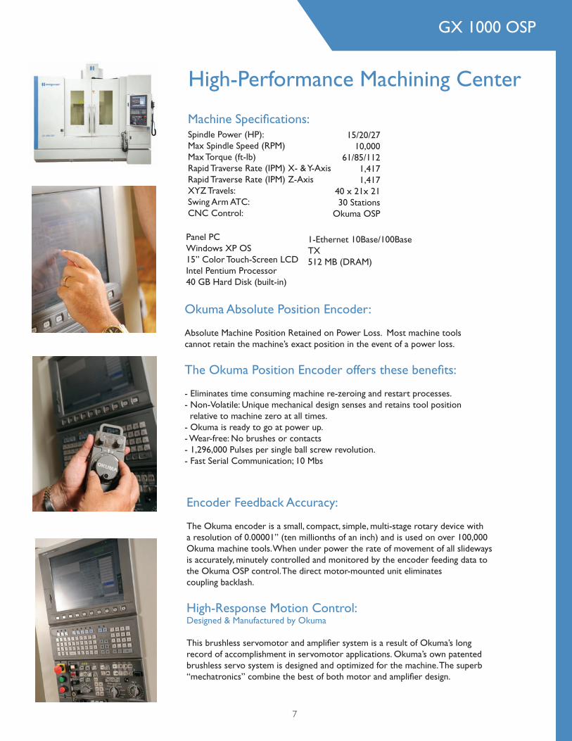
High-Performance Machining Center
Okuma Absolute Position Encoder:
Absolute Machine Position Retained on Power Loss. Most machine tools cannot retain the machine’s exact position in the event of a power loss.
The Okuma Position Encoder offers these benefi ts:
- Eliminates time consuming machine re-zeroing and restart processes. - Non-Volatile: Unique mechanical design senses and retains tool position relative to machine zero at all times. - Okuma is ready to go at power up. - Wear-free: No brushes or contacts - 1,296,000 Pulses per single ball screw revolution. - Fast Serial Communication; 10 Mbs
Encoder Feedback Accuracy:
The Okuma encoder is a small, compact, simple, multi-stage rotary device with a resolution of 0.00001” (ten millionths of an inch) and is used on over 100,000 Okuma machine tools. When under power the rate of movement of all slideways is accurately, minutely controlled and monitored by the encoder feeding data to the Okuma OSP control. The direct motor-mounted unit eliminates coupling backlash.
High-Response Motion Control: Designed & Manufactured by Okuma
This brushless servomotor and amplifi er system is a result of Okuma’s long record of accomplishment in servomotor applications. Okuma’s own patented brushless servo system is designed and optimized for the machine. The superb “mechatronics” combine the best of both motor and amplifi er design.
Machine Specifi cations: Spindle Power (HP): Max Spindle Speed (RPM) Max Torque (ft-lb) Rapid Traverse Rate (IPM) X- & Y-Axis Rapid Traverse Rate (IPM) Z-Axis XYZ Travels: Swing Arm ATC: CNC Control:
15/20/2710,000
61/85/1121,4171,417
40 x 21x 2130 Stations
Okuma OSP
Panel PC Windows XP OS 15” Color Touch-Screen LCD Intel Pentium Processor40 GB Hard Disk (built-in)
1-Ethernet 10Base/100Base TX 512 MB (DRAM)
7
8
OSP Standard SpecificationP200 M Specifications Descriptions P200M
Display / Operating functions
Operation Panel 15 inch XGA liquid crystal display Standard
Language 15 language available (selection of one language only) Standard
OSP WinXShop floor suitable - pointing device not required. Touch panel operation. Trailing pup-up windows. 1-touch window close (all windows)
Standard
Program editing
Simultaneous editing, 2 files in 1 screen. Selected part program edit (file name specify not required) (auto cursor move to executing block). A/B turret simultaneous editing (available for 2 turret model only). Copy, paste, delete of selected range. Add Files. Moves edit pointer (Designates top, end and number of lines). Arranges sequence numbers
Standard
File name index display2 file name indexes displayed in 1 screen. Sorting (by file names, data and size)
Standard
Programming operationsCopies, renames, deletes, protects and verifies programs. Memory initializing, formatting (OSP). Memory available display (by pie chart). Multi-level direc-tory
Standard
Schedule programs Run several programs in a sequence Standard
Sequence number search Machine from the specified sequence number Standard
Sequence stop Stops machining at prescribed sequence number Standard
Manual interrupt, auto return After manual operations, auto mode restarted from interrupted position Standard
Sequence return Return to specified sequence, auto restart from returned point Standard
Library program Registers sub-programs as library (no need to select sub-program) Standard
PLC monitorSupports maintenance work after machine shutdown (Ladder diagram, data trace, etc.)
Standard
Pulse handle overlapping Overlaps manual control by pulse handle onto programmed tool path Standard
Parameter I/O Parameter file input / output, verify Standard
Programming
Basic interpolation Linear interpolation / circular interpolation Standard
Workpiece coordinate system selection 20 sets Standard
Tool compensation Tool length offset and cutter radius compensation; 100 sets Standard
Helical cutting function Circular interpolation + helical axis interpolation Standard
Synchronized tapping function Synchronization of the spindle speed and axis feedrate Standard
Cylindrical side machining Simplified cylindrical side machining Standard
Workpiece geometry conversion Mirror image by switch on operation panel Standard
Online auto programming function (MAP)Coordinate calculation, Area machining function, Coordinate conversion (shift / rotation / copy)
Standard
Arbitrary angle chamfering Easing programming of chamfering with (C, R) Standard
Fixed cycles G73, G74, G76, G81 - G87, G89 (11 kinds) Standard
User task 1IF / GOTO statement, function, arithmetic operation, local variables, system variables, Common variables; 200 sets
Standard
User task 2 Sub programming, functional operation, logical operation Standard
Interactive Programming Function
Interactive MAP function Part program editing with guidance Standard
Programming Capacities
Program storage capacity 2 Gbyte Standard
Operation buffer capacity 2 Mbyte Standard
OSP Standard Specification
Machining Management
Machining record, summary and display Summarizes and displays machining status per selected main programming Standard
Operation record, summary and displaySummarizes and displays machine operating time (power ON, cutting)Allow input of the reason for non-operation
Standard
Operating history, summary and display Summarizes and displays machining operation history by time chart Standard
Trouble information, summary and displayAuto summary of the alarm history, etc, which is necessary for the trouble-shooting
Standard
Operating history and trouble information, file outputCreating file of machining operation, operating history, trouble information, etc.
Standard
Monitoring Function
3D Real Simulation
Real time simulation for all machining status of automatic, MDI and manual operations. Solid, cross section and transparency display. Display by color of machining surface linked with tools. Superimposed display of main program list. With machining time calculation function.
Standard
Load meter Feed and spindle load display, With peak value hold Standard
Simple load monitor Monitors spindle overload (spindle stops when overloaded) Standard
Tool life management functionTotals no. of workpieces or cutting time automatically. Automatic tool change to spare tooling at preset conditions. Graph display of the tool life data per each tool
Standard
Tapping torque monitor function (synchronized tapping)Monitors spindle overload when carrying out synchronized tapping (When CNC detect overload, axis retract cycle start point then stops tapping)
Standard
NC operation monitorHour meter (cutting time, operation time, spindle rotating time, etc.). NC work counter. Optional: RS-232-C (additional 1CH)
Standard
Networking
Brower function Touch panel operation (touch screen). Easy connection to intranet Standard
DNC-T1 Program transfers by Ethernet Standard
High speed / High accuracy function
Hi-G control Positioning acceleration/deceleration according to motor speed and torque Standard
Hi Cut ProControlling speed and acceleration / deceleration of the feedrate according to programmed shape
Standard
Pitch error compensation Ball screw pitch error compensation Standard
Pocket Manual Function (online help)
Programming help Explains part program G, M codes, cycle commands, etc Standard
Operation helpManu display according to screen mode. Explains operation procedure from Menu
Standard
Alarm help Explains causes of alarm and countermeasures to reset alarm Standard
Measurement Functions
Automatic gauging Checks workpiece dimension, and automatically compensates for zero point Standard
Auto tool length offset/ Auto tool breakage detectionAutomatically performs tool length compensation and tool breakage detec-tion
Standard
Others
Inch / metric switchable Selecting inch or metric unit in programming Standard
Inverse Time feed function Sets axis feed rate per cutting time command Standard
THINC-API (Application Programming Interface)
Windows applications can access NC information by opening PC func-tions on NC. User can create user own system speedy and flexible utilizing THINK-API, and user can further the differentiation strategy and increase competitive power.
Standard
4th Axis Preparation (Software Only) For 4th Axis (Rotary Table) Standard
OSP Standard Specification
9
GX 1000
1020mm (40.16”)540mm (21.25”)540mm (21.25”)
145 to 685mm (5.70 to 26.97”)
36m/min (1.417ipm).0025 - 12m/min (0.1-472ipm)
.001mm (0.0004”)40 x 12mm (1.57 x .472”)40 x 12mm (1.57 x .472”)
10,000 rpm11/15/26kW (15/20/34.8hp)
114Nm (84ft-lb)7829N (1,760 lbf)No. 40, Big PlusCT40 or BT40
12,000 rpm15kW (20hp)
95Nm (70ft-lb)15,000 rpm
15kW (20hp)76Nm (56 ft-lb)
1120 x 540mm (44.09 x 21.25”)800 kg (1,760 lb)
318mm (.708”)160mm (6.30”)
i-Series GX
30 ToolsBi-Directional
150mm (5.90”)76.2mm (3.00”)300mm (11.81”)
8kg (17.6 lb)4.5 sec.
Chip Conveyor Option360L (95 US gal)
OptionOptionOptionOption
0.010mm (0.0004”)0.005mm (0.0002”)
2955 x 2190mm (116.30” x 86.22”)2713mm (106.81”)5640kg (12,408 lb)
50 or 60 Hz82 FLA
208 - 230 or 380 - 440 volt5kg/cm2 (70psi)20 bar (300 psi)
49 L/min (13 gal/min) 49 L/min (13 gal/min)
GX 710
710mm (27.95”)400mm (15.75”)430mm (16.93”)
150 to 580mm (5.91 to 22.83”)
36m/min (1.1417ipm).004 - 23.2m/min (0.1-590ipm)
.0001mm (0.00004”)32x16mm (1.26”x.63”)
32 x 12mm (1.26 x .472”)
10,000 rpm5.5/7.5/15kW (7.5/10/20hp) CT/15min/1min*
47.7Nm (35ft-lb)(1500rpm )6,375N(1,430 lbf)No. 40, Big PlusCT40 or BT40
------
800 x 400mm (31.5 x 15.8”)300 kg (661lb)
314mm (.551”)125mm (4.92”)
i-Series GX
20 ToolsBi-Directional
150mm (5.90”)80mm (3.15”)190mm (7.48”)
7kg (15.7lb)4.5 sec.
Chip Conveyor Option120L (31.7 US gal)
OptionOptionOptionOption
0.010mm (0.0004”)0.005mm (0.0002”)
2035 x 2168mm (80.12” x 83.35”)2088mm (82.20”)2930kg (6,460 lb)
50 or 60 Hz64 FLA220 volt
5kg/cm2 (70psi)19.5 bar (280 psi)
49L/min (13 gal/min)49L/min (13 gal/min)
GX 480
480mm (18.90”)400mm (15.75”)430mm (16.93”)
150 to 580mm (5.91 to 22.83”)
36m/min (1.1417ipm).004 - 23.2m/min (0.1-590ipm)
.0001mm (0.00004”)32 x 16mm (1.26 x .63”)32 x 12mm (1.26 x .472”)
10,000 rpm5.5/7.5/15kW (7.5/10/20hp) CT/15min/1min*
47.7Nm (35ft-lb)(1500rpm)6,375 N (1430lbf)No. 40, Big PlusCT40 or BT40
------
600 x 400mm (23.6 x 15.8”)300 kg (661lb)
314mm (.551”)125mm (4.92”)
i-Series GX
20 ToolsBi-Directional
150mm (5.90”)80mm (3.15”)190mm (7.48”)
7kg (15.7lb)4.5 sec.
Chip Conveyor Option120L (31.7 US gal)
OptionOptionOptionOption
0.010mm (0.0004”)0.005mm (0.0002”)
1575 x 2168mm (62.01” x 83.35”)2088mm (82.20”)2820kg (6,204 lb)
50 or 60 Hz64 FLA220 volt
5kg/cm2 (70psi)19.5 bar (280 psi)
49L/min (13 gal/min)49L/min (13 gal/min)
Axis TravelTable (X axis)Saddle (Y axis)Head (Z axis)Table Surface to Spindle Gauge Plane Distance (Min to Max)PositioningAuto Mode (X, Y and Z axes)Feedrate Range (X, Y and Z axes)Minimum IncrementBall Screw Dia. and Pitch (X and Y axes)Ball Screw Dia. and Pitch (Z axis)Spindle 1
Speed (Belted)Motor Power Rating CT/30min/S3 25%*Torque (S3-60%)Retention ForceSpindle TaperTool HolderSpindle Options 1
Speed (Belted) - Grease LubricatedMotor Powerating (S3-60%)Torque (S3-60%)Speed (Belted) - Oil -Air Lubricated Motor Powerating (S3-60%)Torque (S3-60%)WorktableWorking SurfaceTable LoadNumber of T-slotsT-Slot SizeT-Slot Center DimensionControl - Bridgeport/FanucAutomatic Tool Changer - Side-Mount Swing ArmMagazine CapacityTool Select by Shortest Path and Random SelectMax. Tool Diameter (adjacent pockets empty)(adjacent pockets)Max. Tool LengthMax. Tool WeightRandom Change Time (chip to chip)Coolant and Chip ManagementSwarf RemovalCoolant Tank CapacityChip Flush SystemWash Down GunCutter Air BlastThrough Spindle CoolantAccuracy - ISO 230-2Positioning - ARepeatability - RLinear Scales Option (X/Y/Z-Axes)Machine Size Machine Dimensions (WxD)HeightMass of MachineInstallation SpecificationsElectrical Supply (Input) - Balanced 3-phasePowerVoltage2
Compressed Air RequirementThrough Spindle Coolant Option - PressureNozzle CoolantWash Down Option
Specifications
10
1—Spindle Oil Chiller option offered.2—Other voltages require external transformer.
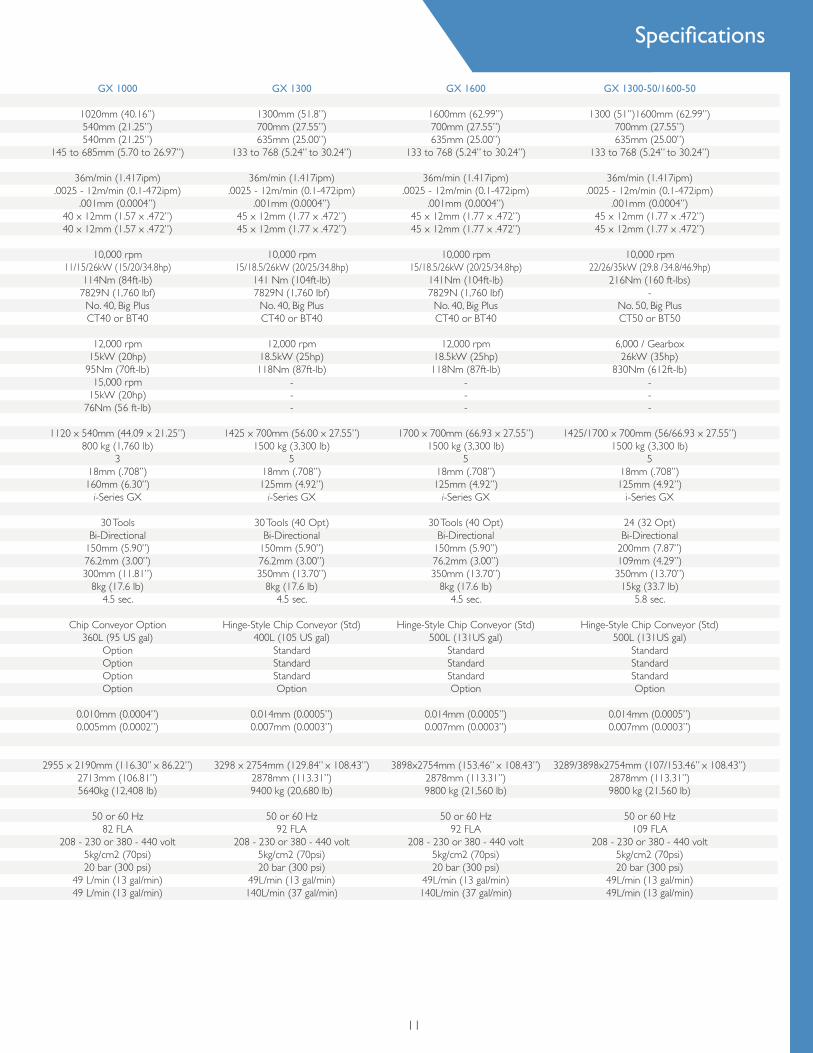
GX 1300
1300mm (51.8”)700mm (27.55”)635mm (25.00”)
133 to 768 (5.24” to 30.24”)
36m/min (1.417ipm).0025 - 12m/min (0.1-472ipm)
.001mm (0.0004”)45 x 12mm (1.77 x .472”)45 x 12mm (1.77 x .472”)
10,000 rpm15/18.5/26kW (20/25/34.8hp)
141 Nm (104ft-lb)7829N (1,760 Ibf)
No. 40, Big PlusCT40 or BT40
12,000 rpm18.5kW (25hp)118Nm (87ft-lb)
---
1425 x 700mm (56.00 x 27.55”)1500 kg (3,300 lb)
518mm (.708”)125mm (4.92”)
i-Series GX
30 Tools (40 Opt)Bi-Directional
150mm (5.90”)76.2mm (3.00”)350mm (13.70”)
8kg (17.6 lb)4.5 sec.
Hinge-Style Chip Conveyor (Std)400L (105 US gal)
StandardStandardStandardOption
0.014mm (0.0005”)0.007mm (0.0003”)
3298 x 2754mm (129.84” x 108.43”)2878mm (113.31”)9400 kg (20,680 lb)
50 or 60 Hz92 FLA
208 - 230 or 380 - 440 volt5kg/cm2 (70psi)20 bar (300 psi)
49L/min (13 gal/min)140L/min (37 gal/min)
GX 1600
1600mm (62.99”)700mm (27.55”)635mm (25.00”)
133 to 768 (5.24” to 30.24”)
36m/min (1.417ipm).0025 - 12m/min (0.1-472ipm)
.001mm (0.0004”)45 x 12mm (1.77 x .472”)45 x 12mm (1.77 x .472”)
10,000 rpm15/18.5/26kW (20/25/34.8hp)
141Nm (104ft-lb)7829N (1,760 Ibf)
No. 40, Big PlusCT40 or BT40
12,000 rpm18.5kW (25hp)118Nm (87ft-lb)
---
1700 x 700mm (66.93 x 27.55”)1500 kg (3,300 lb)
518mm (.708”)125mm (4.92”)
i-Series GX
30 Tools (40 Opt)Bi-Directional
150mm (5.90”)76.2mm (3.00”)350mm (13.70”)
8kg (17.6 lb)4.5 sec.
Hinge-Style Chip Conveyor (Std)500L (131US gal)
StandardStandardStandardOption
0.014mm (0.0005”)0.007mm (0.0003”)
3898x2754mm (153.46” x 108.43”)2878mm (113.31”)9800 kg (21,560 lb)
50 or 60 Hz92 FLA
208 - 230 or 380 - 440 volt5kg/cm2 (70psi)20 bar (300 psi)
49L/min (13 gal/min)140L/min (37 gal/min)
GX 1000
1020mm (40.16”)540mm (21.25”)540mm (21.25”)
145 to 685mm (5.70 to 26.97”)
36m/min (1.417ipm).0025 - 12m/min (0.1-472ipm)
.001mm (0.0004”)40 x 12mm (1.57 x .472”)40 x 12mm (1.57 x .472”)
10,000 rpm11/15/26kW (15/20/34.8hp)
114Nm (84ft-lb)7829N (1,760 lbf)No. 40, Big PlusCT40 or BT40
12,000 rpm15kW (20hp)
95Nm (70ft-lb)15,000 rpm
15kW (20hp)76Nm (56 ft-lb)
1120 x 540mm (44.09 x 21.25”)800 kg (1,760 lb)
318mm (.708”)160mm (6.30”)
i-Series GX
30 ToolsBi-Directional
150mm (5.90”)76.2mm (3.00”)300mm (11.81”)
8kg (17.6 lb)4.5 sec.
Chip Conveyor Option360L (95 US gal)
OptionOptionOptionOption
0.010mm (0.0004”)0.005mm (0.0002”)
2955 x 2190mm (116.30” x 86.22”)2713mm (106.81”)5640kg (12,408 lb)
50 or 60 Hz82 FLA
208 - 230 or 380 - 440 volt5kg/cm2 (70psi)20 bar (300 psi)
49 L/min (13 gal/min) 49 L/min (13 gal/min)
11
GX 1300-50/1600-50
1300 (51”)1600mm (62.99”)700mm (27.55”)635mm (25.00”)
133 to 768 (5.24” to 30.24”)
36m/min (1.417ipm).0025 - 12m/min (0.1-472ipm)
.001mm (0.0004”)45 x 12mm (1.77 x .472”)45 x 12mm (1.77 x .472”)
10,000 rpm22/26/35kW (29.8 /34.8/46.9hp)
216Nm (160 ft-lbs)-
No. 50, Big PlusCT50 or BT50
6,000 / Gearbox 26kW (35hp)
830Nm (612ft-lb)---
1425/1700 x 700mm (56/66.93 x 27.55”)1500 kg (3,300 lb)
518mm (.708”)125mm (4.92”)
i-Series GX
24 (32 Opt)Bi-Directional
200mm (7.87”)109mm (4.29”)350mm (13.70”)15kg (33.7 lb)
5.8 sec.
Hinge-Style Chip Conveyor (Std)500L (131US gal)
StandardStandard StandardOption
0.014mm (0.0005”)0.007mm (0.0003”)
3289/3898x2754mm (107/153.46” x 108.43”)2878mm (113.31”)9800 kg (21.560 lb)
50 or 60 Hz109 FLA
208 - 230 or 380 - 440 volt5kg/cm2 (70psi)20 bar (300 psi)
49L/min (13 gal/min)49L/min (13 gal/min)
Specifications
All specifi cations subject to change without notice. All marks indicated by ® and ™ are trademarks of their respective owners.
Brochure #1353D • Litho in USA • ©Hardinge Inc. 2011 • September 2011
Hardinge Companies WorldwideNorth AmericaHardinge Inc. One Hardinge Drive Elmira, NY 14902-1507 USA General Information: 607-734-2281 Sales Fax: 607.734.8819 Workholding Fax: 607.734.3886 Service: 800.424.2440 web site: www.hardinge.com
In Canada: Canadian Hardinge Machine Tools Ltd. Phone: 800.468.5946 Fax: 607.734.8819
China Hardinge Machine (Shanghai) Co. Ltd.Hardinge China Limited No.1388 East Kang Qiao Road Pudong , Shanghai 201319 Tel : 0086 21 38108686 Fax: 0086 21 38108681
Germany Hardinge GmbH Fichtenhain A 13 C 47807 Krefeld Germany Phone: (49) 2151 496490 Fax: (49) 2151 4964999
Taiwan Hardinge Machine Tools B.V. 4 Tzu Chiang 3rd Road Nan Tou City 540 Taiwan, R.O.C. Phone: 886 49 2260536 Fax: 886 49 2252203 e-mail: [email protected]
Switzerland L. Kellenberger & Co. AG Heiligkreuzstrasse 28 Postfach Ch-9009 St. Gallen Switzerland Phone: +41 (0) 71 242 91 11 Fax: +41 (0) 71 242 92 22 e-mail: [email protected] web site: www.kellenberger.net
L. Kellenberger & Co. AG Längfeldweg 107 CH-2500 Biel-Bienne 8 Switzerland Phone: +41 (0)32 344 11 52 Fax: +41 (0)32 341 13 93 e-mail: [email protected] web site: www.kellenberger.net
United KingdomHardinge Machine Tools, Ltd. Whiteacres Cambridge Road Whetstone Leicester LE8 6BD England Tel: +44 (0)116 2869900 Fax: +44 (0)116 2869901 Hardinge e-mail: [email protected] Hardinge web site: www.hardinge.co.uk
Jones & Shipman Precision Limited Murray Field Road Leicester LE3 1UW, UK Tel: +44 (0) 116 2013000 Fax: +44 (0) 116 2013001 e-mail: [email protected] web site: www.jonesshipman.com
Over the years, The Hardinge Group™ steadily
diversifi ed both its product offerings and opera-
tions. Today, the company has grown into a
globally diversifi ed player with manufacturing
operations in North America, Europe and Asia.
In addition to designing and building turning
centers and collets, Hardinge is a world leader in
grinding solutions with the addition of the
Kellenberger, Jones & Shipman, Hauser and
Tschudin brands to the Hardinge family. The
company also manufactures Bridgeport machin-
ing centers and other industrial products for a
wide range of material cutting, turnkey automa-
tion and workholding needs.
Expect more from your Hardinge products.
Choose Hardinge precision and reliability
for increased productivity and value!
Call us today, we’ve got your answer.