Embed Size (px)
Citation preview

Agilent E3238S/35688E Signal
Intercept and Collection System
Product Overview
Deploy Quicker, Produce Faster
• Increase the probability of intercept for
off-the-air RF signals
• Re-configure signal detection without programming to
increase probability of intercept
• Quickly categorize and select target signals using visual,
audible, and analytic tools
• Improve mission productivity by automating common
processing tasks and mission setups
• Complete solutions to support tactical operations
including demodulation and decoding of
device-specific signals
• Increase interoperability and re-use through integration
with legacy systems and open programming capability
• Scalable performance from simple survey solutions to
completely integrated intercept and collection solutions
• Rapidly deployable solution based upon industry-standard
off-the-shelf components

2
Operator Tools forInvestigating theRF Spectrum
The tools you require depend on
the amount of knowledge you have
about the target. The E3238S/35688E
supports missions from the simple,
such as cataloging the signal
environment, to the complex such
as interception and collection of
information from specific devices and
users.
Survey
Initially, the operator must survey
RF spectrum for signal energy. Since
the number and variety of signals is
so large, and the spectrum so vast,
efficiency is critical. The hardware
must be able to search for new signals
as they appear, and the operator must
have the tools to quickly determine the
kinds of signals that are present.
Collection
Once the types of signals of interest
are known, a system can be put in
place to collect them, usually by
recording them for later analysis. To
increase mission efficiency, the system
must be able to differentiate between
modulation types, and collect signals
of the target types only. Even then, the
task of sorting through the recorded
signals can be time consuming.
Analysts may need to determine how
to demodulate the signals, or linguists
may need to listen to each signal to
determine if it is important. The goal is
to rapidly identify the specific devices
and users so that no critical signal will
be missed.
Universal signal detection
The universal signal detection option
spans both survey and collection. A
universal signal detector automatically
identifies signals of interest by
operating on the characteristics of
RF transmissions. Agilent’s universal
signal detection (Option USD) includes
bandwidth filters, frequency plans,
wideband detectors, and narrowband
confirmers. These wideband and
narrowband technologies are
combined to efficiently sift through the
crowded spectrum and significantly
increase the probability of intercept.
As signals of interest are detected,
simultaneous gap-free recordings (or
data streams) are easily handled by
the multiple digital down converters
(DDC) and parallel DSPs in the E3238S
system. When a new threat emerges
you can quickly build a detector from
a recording of a new signal without
programming.
Device-specific applications
Once specific devices have been
identified, and critical identifying
information such as pager capcodes,
phone numbers, and communication
frequencies and times have been
extracted, then device-specific
demodulators and decoders can
be put in place to capture signals
of interest as they occur. For data
transmissions, the message content
can be put in a searchable database,
real-time searches can be performed
and reports generated. For voice
transmissions, operators can listen to
the communications as they occur to
support tactical operations.
Total RF Spectral Energy Target Message Content
Survey
• Detect new energy in the spectrum
• Catalog the signals present using various tools
• Automatically document results
Collection
• Detect new energy in the spectrum
• Automatically record signals meeting defined parameters
• Post-process signals and search for signals of interest
Device-Specific Content
• Detect new energy in the spectrum
• Automatically record signals from specific kinds of devices or specific users
• Automatically create searchable databases of message content and perform real-time searches for critical information

3
Wideband Search Increases Probability of Intercept
The E3238S uses a wide-band stepped
FFT technique to achieve exceptionally
fast sweep rates while maintaining
high resolution and wide dynamic
range. Unlike swept analyzers, the
E3238S concatenates several FFTs so
you can zoom in closer and still resolve
spectral detail. Up to six Motorola G4
processors compute FFTs, allowing
10 GHz/sec sweep rates. Broad
expanses of spectrum are covered
quickly, and frequencies of interest
are revisited often to intercept short
signals. The E3238S hardware has
the dynamic range to dig signals out
of noise, the frequency resolution
to isolate small signals hiding next
to large ones, and fast sweep rates
to capture signals just fractions of a
second long.
Mission-specific hardware
configurations
The E3238S hardware can be
configured to target specific
frequency ranges and missions, then
reconfigured as needs change. HF,
VHF/UHF, and Microwave (μWave)
systems are possible – only the
tuners need to be changed to target a
different frequency range. The rest of
the system stays the same. The new
Agilent N6830A is a dual channel HF
receiver and 70 MHz IF ADC configured
for monitoring HF signals from 100 kHz
to 32 MHz, as the IF ADC for V/UHF
or microwave tuners, or for dual
channel applications. Systems can
be easily upgraded as new hardware
becomes available, saving hardware
and training expense. Agilent can
support new technologies faster, since
the entire system does not need to be
redesigned.
Narrowband collection
E3238S systems can be configured
with hundreds of narrowband
channels, each with independently
programmable center frequencies
and bandwidths. Several signal
processing algorithms can run
simultaneously, targeting multiple
signal types. Information extracted
from signals goes into a searchable
Signal Database where it is logged and
user-defined alarms can be generated,
allowing alarming on specific message
content.
The basic search system controls the system
tuner, analog to digital convertor (ADC) and G4
based DSP hardware to provide industry leading
performance and high probability of intercept of
unknown/unwanted emitters.
µWave Tuner
E4440A PSA
100 k to 26.5 GHz
36 MHz BW
V/UHF Tuner
E2731B
20 to 6000 MHz
36 MHz BW
HF Receiver
N6830A
0.1 to 32 MHz
32 MHz BW
IF ADC
N6830A
95 MSa/sec
36 MHz BW
DSP
E9821A
6 G4 floating point
processors
Controller
LTPC2
Windows® XP
Control
4
Process Flow Diagram
Wideband Survey
time snapshot
Alarm Tasks
frequency/ snapshot
universal
handoff
audio
visual
user tasks
Energy Detection
spectrum data
freq, amp and BW data
thre
shold
funct
ion
searchhardware
BW
filt
ers,
fr
equen
cy p
lans,
w
ideb
and
dete
ctors
ener
gy d
etec
tion
calc
ula
te b
andw
idth
para
met
er e
xtra
ctio
n
pre-
filt
er
SURVEY
new energy log
post filter
alarm log
frequency lists
new-energydatabase
energyalarms
Narrowband Collection and Signal Processing time
snapshot
Alarm Tasks
frequency/ snapshot
handoff
audio
visual
user tasks
narrow-bandtime-domain data
DDC Channelizerhardware
alarm log
signaldatabase
signalalarms
signalprocessing
universal:narrowbandconfirmation
…
narrowbandprocessing
narrowbandprocessing
COLLECTION(PATH 1)
DEVICE-SPECIFIC APPLICATIONS(PATH 2)
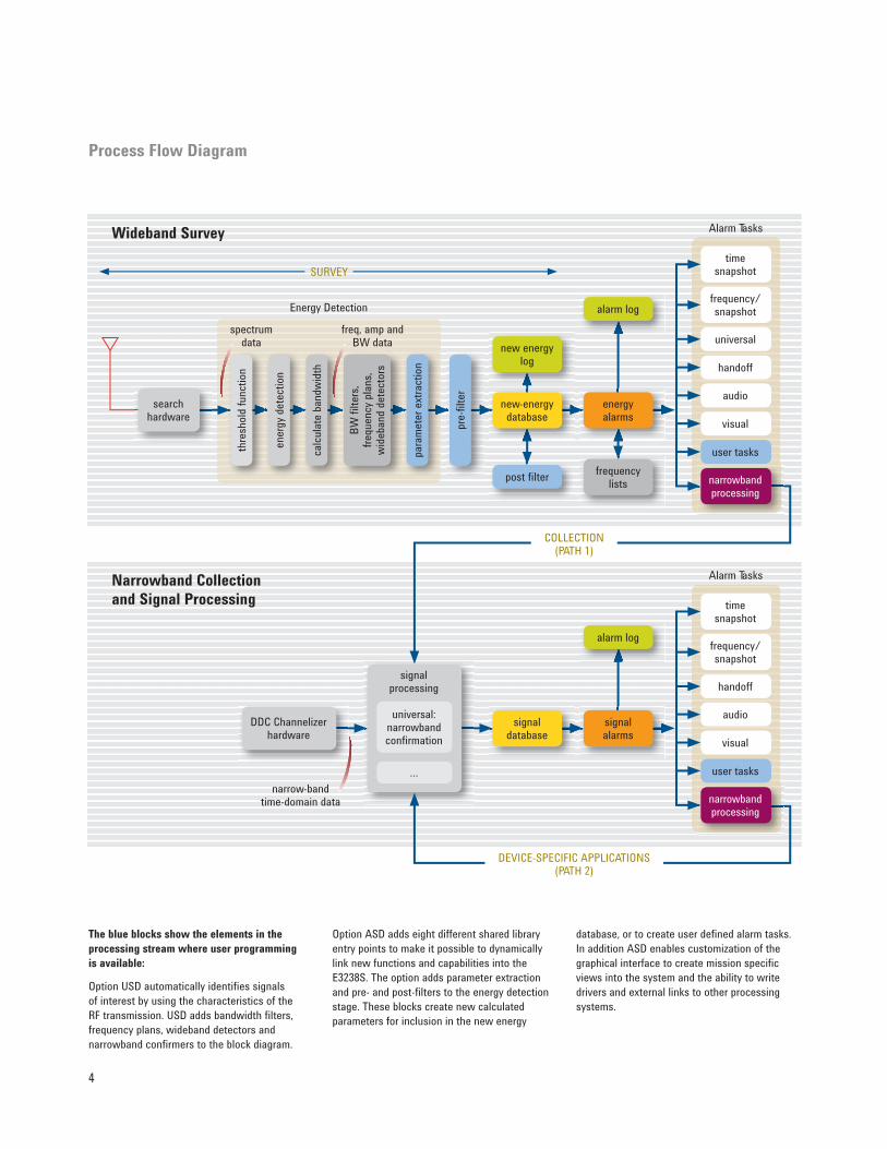
The blue blocks show the elements in the
processing stream where user programming
is available:
Option USD automatically identifies signals
of interest by using the characteristics of the
RF transmission. USD adds bandwidth filters,
frequency plans, wideband detectors and
narrowband confirmers to the block diagram.
Option ASD adds eight different shared library
entry points to make it possible to dynamically
link new functions and capabilities into the
E3238S. The option adds parameter extraction
and pre- and post-filters to the energy detection
stage. These blocks create new calculated
parameters for inclusion in the new energy
database, or to create user defined alarm tasks.
In addition ASD enables customization of the
graphical interface to create mission specific
views into the system and the ability to write
drivers and external links to other processing
systems.

5
Processing Flow Overview
The purpose of the E3238S is to detect,
identify and collect signals of interest
(SOI) in the RF spectrum.
The system is connected to an
antenna or other energy source
for signal acquisition. The energy
presented at the input to the system is
the wideband RF spectrum.
The search hardware acquires the
signal and converts it into spectrum
data.
The spectrum data is processed in
two ways:
1. As wideband data in the
WIDEBAND Search mode of
operation
2. Broken out into narrowband data
for the NARROWBAND collection
and signal processing
The Narrowband Signal Processing
chain is generally used to do one of
three things to the energy detected at
the end of the processing chain.
• Identify (type of signal)
• Locate (direction finding)
• Collect (record and demodulate)
As an example, consider the need to
search, detect and collect a specific
FSK signal from the RF Spectrum, and
then determine signal location.
Wideband Search:
Energy Detection to Alarm Tasking
This section performs wide-band
processing of all the signals in the
RF environment and filters out all but
the most likely signals of interest.
The RF energy that makes it through
this filtering process is entered into
the energy history along with their
continuously-updated statistics. If the
energy matches the criteria for the
target RF energy, an Energy Alarm is
triggered which will cause an Alarm
Task to execute. There are many
different types of Alarm Tasks that can
be executed as result of an Energy
Alarm. One of the most powerful Alarm
Tasks is to execute further Narrowband
Processing to extract signal content.
Narrowband Collection and
Signal Processing:
Extracting Signal Content
The next section of processing
operates on narrow-band time domain
data that is extracted from the
wideband data stream via the Digital
Down Convertor Channelizer hardware.
As an example, assume that an energy
alarm from the wideband search
detected energy of interest that looks
like an FSK signal in the wideband data
stream. The parameters about this
energy like frequency and bandwidth
is passed to the narrowband collection
and processing chain (see page 4,
Processing Flow diagram, PATH 1).
The narrowband data is further
processed into signal specific
information and entered into the Signal
Database. At this point we know
we have a potential FSK Signal Of
Interest, but we don’t yet have actual
demodulated information content from
the signal.
A Signal Alarm is established that
tests for a specific FSK signal to
appear at a certain time of day at a
given frequency assignment. When
that signal is detected, another
narrowband processing task is
executed (Processing Flow diagram,
PATH 2) to record the signal to disk
and also to apply further narrowband
demodulation processing to extract the
actual information content from the
signal.
Integrating with Legacy Datastreams
Since the E3238S is defined with
socket protocols, connection and
integration with legacy sub-systems
make the E3238S the ideal operator
control center for signal identification
and collection missions. Consider the
FSK detected in the example. With a
connection between the E3238S and a
legacy Direction Finding system, data
from the E3238S is used to “tip off”
the Direction Finding system as to the
presence of energy, and then receive
back the line of bearing and other
geolocation parameters for entry into
the signal database. Now we have a
complete solution to identify, locate,
and collect the specific FSK signals
coming from a specific line of bearing
or location.

6
Designed to speed Intercept and Collection tasks and increase probability of intercept (POI):
1 Cockpit control of all systems assets from antennas to digital receivers via the system icon bar
2 A variety of signal visualization tools speed analysis
3 Operators eyes never leave the signal of interest while they interact directly with trace data to control assets like drop receivers, Modulation
Recognition, and Direction Finding systems
4 Automated alarms, thresholding and alerts automate the task of keeping track of incoming signals
5 Signals Database automatically logs all signals of interest for historical use
6 Wideband detector technologies in the universal signal detection option use shape, peaks, or limit lines to quickly identify signals of interest
7 Quickly identify unknown emitters with the Modulation Recognition option
8 Integration with legacy systems completes the solution, shown here with Direction Finding results
1
2
3
4
5
8
76

7
Versatile tools for the survey task
Everything within the E3238S user
interface is designed to increase an
operator’s efficiency during a mission.
The key to efficiently surveying and
collecting signals is to provide the
operator with an integrated suite of
tools for controlling the system.
Optimized graphical user interface
The E3238S’s easy-to-use graphical
user interface is designed to speed
signal detection in dense signal
environments. Simple toolbars
are used to configure the system
hardware, setup and control the search
and collection subsystem, and finally
to present various user displays and
visualization tools.
High-speed visual displays
Display types with very high update
rates show how signals change over
time. Multiple displays can reveal
broad and close-up view of signals
simultaneously. Whether the signals
are stationary or moving, burst
or continuous, low-level or high-
power, the E3238S’s spectrum and
spectrogram displays have the speed
and resolution needed to resolve fine
details.
Audible tools to classify signals
The E3238S can easily hand-off
signals to traditional single channel
hand-off receivers, or transfer them
to the 35688E-AU1 software-based
AM/FM handoff receiver. Voice
signals can be listened to directly.
Many digital signals have distinctive
sounds that reveal the signal type
to an experienced operator. Manual
or automatic modes let the operator
assign monitoring and collection
assets to signals of interest. Software
drivers are provided for handoff
receivers from companies such as
Cubic Communications, ICOM, and
others.
Reconfigure without programming
Universal signal detection and
modulation recognition technologies
are powerful tools that can easily be
adapted for various missions. When a
new threat emerges you can quickly
build a detector from a recording of the
new signal without programming.
Capturing direction information
Signal parameters can also be passed
to a direction finding sub-system. The
returned geolocation information like
azimuth and elevation is integrated in
the marker display and saved in the
Signal Database.
Tying it all together with markers
Markers and the mouse work together
to increase efficiency. Direction
finding, handoff receivers, and
modulation recognition can all be
linked to markers. A click of the mouse
steps the marker from peak to peak,
automatically passing center frequency
and bandwidth to the DF subsystem,
modulation recognition algorithm, or
handoff receiver. The operator can
listen to the signal while the DF and
modulation type information update in
the marker display area.
Record a signal for later analysis
During a mission, signals can be
recorded for later analysis. The
ADC zooms its center frequency
and bandwidth to slice the signal of
interest out of the spectrum. Its time
data is recorded and sent to the host
computer where analysts can evaluate
it later.

8
Automate Survey Missions to Increase Productivity
Automation is the key to increasing
signal detection intercept and
collection productivity. The E3238S
automatically detects and logs energy
events into an energy history. Tools to
filter energy into and out of the energy
history are key to reducing operator
workload and increasing Probability of
Intercept.
Automatic new-energy detection
Automatic signal classification starts
with isolating potential signal energy
from noise energy. To determine when
new energy appears in the spectrum,
an energy threshold is established. The
E3238S offers three standard energy
thresholds.
The first threshold that operators
can select is the level threshold. The
level threshold is most effective when
the noise floor is flat and reasonably
constant. It can be visually adjusted to
a position as close to the noise floor as
the task demands.
The next threshold that operators
may choose is the noise-riding auto
threshold. The auto threshold is best
for HF missions, or anytime the noise
floor is contoured or changing. This
noise-riding threshold automatically
shapes itself to the noise floor and is
recalculated for each new sweep. The
auto threshold dramatically increases
POI in HF search.
The third and last standard threshold
is called the environment threshold
which can reveal changes to the signal
environment from one time period to
another. The environment threshold
memorizes the environment on
command and then subtracts it from
the spectrum display. The operator
only has to monitor signals not
previously present. The environment
threshold can be saved and used at
a later time to see if new signals are
present.
Custom environment thresholds can
also be built with a text editor or a
spreadsheet program.
Automated energy history
When any energy exceeds the
threshold it is automatically
characterized and its parameters are
entered in the energy history. The
energy history records frequency,
bandwidth, amplitude and duration of
all energy above the threshold. It also
calculates the minimum, maximum,
and average values of the amplitude,
bandwidth and duration of each signal,
the percent occupancy, and the date
and time of the first and last intercept.
The energy history is critical in
documenting the survey of a signal
environment, but plays an even more
critical role for collection, where
parameters are used to create alarms.
Automatic documentation
The energy history display shows a summary of information
in the energy history for all signals that exceed the threshold.
Clicking on a line of the Energy History opens the dialog box
(bottom right), which shows all information for the energy at
that frequency. The handoff log saves all information about
the use of handoff receivers, and the alarm log records any
alarm that has triggered. In this display, alarms have triggered
to task the direction finding system, and to call the UHF/VHF
voice activity detection algorithm (see page 21 for more
information).

9
Level threshold
This threshold works well when the noise floor is flat and unchanging, as it
often is in VHF/UHF and μWave Spectrum.
Auto-threshold
Auto-threshold shapes itself to the noise floor. This is especially important
in HF, where the noise floor is not flat, and changes with the time of day
and year. Since the auto-threshold is automatically recalculated with each
new sweep, it can adapt to changes, which significantly increase the
probability of intercepting HF signals.
Environmental threshold
This threshold takes a snapshot of the spectrum and creates a threshold
that matches the spectral shape at that time. It can be used at a later time
to see if new signals are present. In this case there are three new signals
that were not present when the original threshold was created, and two
signals are not present now. Notice that only the new signals appear in the
spectrogram display.

10
Signalsdatabase
Alarms and alarm tasks
Narrowband digital down converters
Energy history
Time delay
Energy detection threshold
High resolution and high
speed search engine
Bandwidth filter
Frequency plan
Wideband detection
Signalprocessing
Narrowbandconfirmation
… Recordings or streaming data
A universal signal detector
automatically identifies signals
of interest by operating on the
characteristics of RF transmissions.
Agilent’s Universal Signal Detection
option includes a bandwidth filter, a
frequency plan, wideband detectors,
and narrowband confirmers.
These wideband and narrowband
technologies are combined to create
universal signal detectors that
efficiently sift through the crowded
spectrum and significantly increase
the probability of intercept. As signals
of interest are detected, simultaneous
gapfree recordings (or data streams)
are easily handled by the multiple
digital down converters (DDC) and
parallel DSPs in the E3238S system.
When a new threat emerges you
can quickly build a detector from a
recording of a new signal without
programming.
Universal Signal Detection (Option USD)
Bandwidth filter and frequency plan
For energy that appears above a threshold, a signal detector’s bandwidth
filter and frequency plan will remove signals that don’t meet the criteria
for the signal of interest. The frequency plan can include individual
frequencies, bands of frequencies, or the channelized bands.

11
Wideband detection
USD’s wideband detection operates on the frequency-domain results of
each sweep. When energy is detected in the frequency spectrum, that
portion of the frequency spectrum is processed by one or more wideband
detectors. The wideband detectors quickly determine if the energy is a
potential signal of interest by comparing its magnitude spectrum to the
wideband detectors you created. It passes signals programmatically as
opposed to a human viewing the spectrum data. The wideband detector
techniques that are supported in USD are shape, peaks and limit lines.
Narrowband confirmation
USD’s narrowband confirmation operates on the complex time-domain
data from signals that meet the bandwidth, frequency, and spectral shape
criteria. When used with Agilent’s modulation recognition option MR1,
the modulation format, symbol rate, (and frequency spacing for FSK)
are compared to criteria for the signal of interest. Agilent’s narrowband
confirmation takes full advantage of the E3238S system’s DDCs and
parallel DSPs.

12
Automated modulation recognition
Modulation Recognition (Option MR1) is used to identify modulation
types on signals of interest. Option MR1 provides a library of analog and
digital modulation recognizers. Option MR1, when coupled with option
USD, allows the Modulation Recognition application to run on all active
narrowband channels at the same time.
Popular modulation types supported with Option MR1:
• Noise • 128 QAM
• Unknown digital • 256 QAM
• MSK • AM
• FM MSK • AM DSBSC
• FSK • LSB
• 3 level FSK • USB
• 4 level FSK • Analog FM
• 8 level FSK • Pure Carrier
• BPSK • Manual Morse
• QPSK • Machine Morse
• PI/4 QPSK • OOK
• 8 Level PSK • FM OOK
• 16 Level PSK • 4 PAM
• 16 QAM • V.29
• 32 QAM • Any
• 64 QAM
Design, monitor and run universal signal detectors
Universal Signal Detection has separate development and run modes for
maximizing efficiency for the developer and the operator. In the design
environment, you create and test signal detectors. Because you make
inputs into dialog boxes, pull-down menus, and check boxes, programming
is not needed to detect and capture signals of interest. There’s a
straightforward design flow that helps you create signal detectors. Once
the signal detector is designed, it is stored in a library. There is no limit
to the number of detectors stored in the library. Up to 23 signal detectors
can be running at one time. In run or monitor mode, operators can add
signal detectors “on-the-fly” from the library that was previously created.
A mission set up can load numerous detectors and automatically begin the
search for specific signals.
13
After surveying the RF spectrum for
energy that matches target criteria,
the next step is to determine which of
the signals are “Signals of Interest.”
Additional processing is applied to
the narrower bandwidth data streams
starting with alarm determination
and subsequent narrowband signal
processing.
Energy alarms trigger collection
Automated alarms are the foundation
of the E3238S’s signal detection and
collection capabilities.
The energy history is used for
documenting the parameters of signals
that exceed the threshold and for
testing against Energy Alarm criteria.
Any combination of the energy
parameters in the energy history can
be used as alarm criteria. Without
writing any software, an operator
can create an alarm that is a logical
expression of the Alarm Criteria
parameters in the energy history.
If the logical expression is true,
operatorselected alarm tasks are
automatically executed. The task or
tasks to be executed are chosen by
the operator when the energy alarm is
created.
Collection Using Alarming and
Narrowband Processing
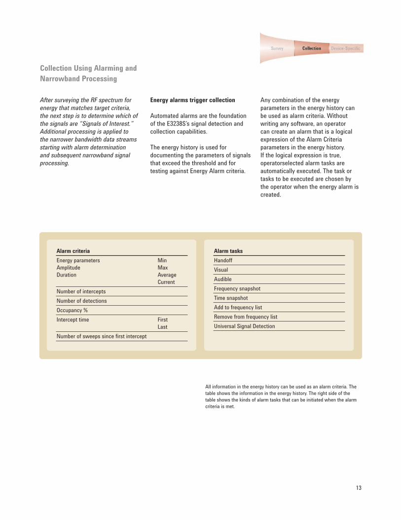
All information in the energy history can be used as an alarm criteria. The
table shows the information in the energy history. The right side of the
table shows the kinds of alarm tasks that can be initiated when the alarm
criteria is met.
Alarm criteria
Energy parameters
Amplitude
Duration
Min
Max
Average
Current
Number of intercepts
Number of detections
Occupancy %
Intercept time First
Last
Number of sweeps since first intercept
Alarm tasks
Handoff
Visual
Audible
Frequency snapshot
Time snapshot
Add to frequency list
Remove from frequency list
Universal Signal Detection

14
Energy alarm creation
Energy alarms are created using the dialog box
shown above. For all energy that exceeds the
threshold, the E3238S compares the information
in the energy history to the conditions specified
in the alarm. In this case the alarm is looking
for energy starting at 11:30 for 1 hour with a
bandwidth of less than 500 kHz, and a center
frequency between 310 MHz and 320 MHz.
If any entry in the energy history meets these
criteria, a new record is created in the alarm log
and a narrowband recording is created.

15
Scalable signal processing
The E3238S DSP hardware scales either by
adding plug-in modules onto the E9821A signal
processor mainboard, or adding additional
complete E9821A modules to the system. The
configuration above shows Signal Processor
1 performing search and 32 channels of
collection using a combination of G4 DSP plug
in modules and 32 Channel DDC modules. The
optional Signal Processor 2 shows a second
E9821A configured for an additional 64 channels
of collection and/or device-specific signal
demodulation and decoding. Additional E9821A
Signal Processor boards are easily added if more
channels or different types of signal processing
are required.
Narrowband processing capabilities
Energy alarms are a critical tool in
the survey application, automating
handoff receivers, recording time
and spectral snapshots, and creating
critical frequency lists. But the real
power of the E3238S is revealed
when an energy alarm task hands off
signals for narrowband processing in
the E3238S’s E9821A signal processor
modules.
The E9821A signal processor’s
32-channel digital downconvertors
(DDCs) select narrowband channels
out of the wideband data and pass
their time data to G4 processors
for further computations. E9821A’s
can be configured with hundreds of
narrowband channels, and multiple
E9821A’s can be used to scale to even
higher channel counts.
Hundreds of narrowband channels
can be processed simultaneously,
and numerous algorithms can be run
on the narrowband channels. The
algorithms can be selected depending
on the energy alarm criteria, and be
initiated as alarm tasks.

16
Alarm Tasked Collection
Collection – recording signal
information
One simple example of narrowband
processing is narrowband recording. In
this process, narrowband time data is
sent to the host and recorded to disk.
The Digital Down Convertor (DDC) can
be passed the center frequency and
bandwidth by the energy alarm, and
the recorded narrowband time data
can be analyzed at a later time.
Another example of narrowband
processing is FM detection and
recording. In this process the G4
processors run an algorithm to
determine if the signal has FM
modulation, and only records those
signals present with that modulation
type. This type of automated
processing dramatically reduces the
number of signals to be recorded, and
simplifies post analysis.
Getting at the message content
In some cases you may want to
dig even further into the signal,
demodulating and decoding it, then
alarming on specific message content.
This is possible in the E3238S by using
signal alarms.
Voice activity alarm collection task
In this example, an alarm task has called the
VHF/UHF voice activity detection algorithm,
35688E-VA2, that executes in the G4 processors.
If a signal appears to be human voice, then the
signal is logged. The dialog box shows that
31 DDC channels have been dedicated to the
voice detection algorithm, and seven of them
are currently active, designated by the colored
buttons. Channels 5, 6, 8, 10, 12, 16, and 17 are
testing for voice. Channels 3, 7, 11, 14, and 15
have detected voice and are currently recording
it. Channels 1, 2, 4, 9, and 13 have detected
voice and are being recorded, but the signal has
currently gone away. The spectrum of channel 7
is being displayed. Channels 18 through 31 are
unassigned. Handoff receivers can be linked to
the buttons so that pressing a button hands that
channel to a handoff receiver so that it can be
listened to in real-time.
The alarm criteria for a signal
alarm is information extracted from
the message by a device-specific
demodulation and decoding
algorithm. Such information is saved
in a dedicated Signal Database.
If the signal information includes
identifying information, such as
telephone numbers, pager capcodes,
or communication callsigns, these
can be used as signal alarm criteria
to identify communications from
specific individuals. By intercepting the
communications of specific individuals
the E3238S can be used for both
strategic information gathering and
realtime tactical missions.

17
Collection Applications
The E3238S has several software
options that recognize and record
specific kinds of signals for later
analysis.
FM Signal Recognizer
The 35688E-FMR software for the
E3238S detects VHF/UHF frequency
modulated signals and records the
undemodulated narrowband time
data to the E3238S system disk. It
can record voice or data signals.
There is a full solution for identifying
and capturing voice signals, the
35688E-VA2 software. (See information
on page 21.)
To use the FM Recognizer software, an
operator creates an energy alarm that
identifies energy with the bandwidth
of the signals intercepted. The alarm
task chosen for this alarm is FM
Recognizer.
When energy of the correct bandwidth
is detected, the center frequency is
passed to an available DDC channel.
It selects that channel from the
wideband data, and passes it to the
the G4 processors which test to see if
it is an FM signal. If it is, the signal is
recorded to the system disk.
CTCSS Signal Recognizer
Some FM radios transmit a low
frequency tone, commonly referred
to as a CTCSS tone, along with the
message. The receiving radio can
then squelch any signals that do not
have the correct low frequency tone,
dramatically reducing the number
of signals received, providing a
more private communication link.
Since there are several different low
frequency tones, several different
semiprivate links are available.
The 35688E-PLR CTCSS Signal
Recognizer software is very similar
to the FMR software, except it only
records FM signals that have the target
low frequency tone. If the CTCSS tone
of the target user is known, recording
signals with that tone allows the
E3238S to intercept and record only
those critical communications.
Dual-tone Multi-Frequency (DTMF)
Signal Detection
The 35688E-DTM software option
detects, decodes and records
FM signals containing Dual-Tone
Multi-Frequency dialing tones.
With the DTM option, your signals
of interest will be processed to
include only signals with the familiar
Touch-Tone keypad frequencies.
The Alarm Setup dialog box above shows a
logical expression of new-energy parameters.
The checkboxes in the Tasks section, indicate
which alarm tasks are called, in this case the
CTCSS Alarm Task and the FM Alarm Task. The
dialog boxes to the left show the parameters of
the alarm tasks. The “Signal Processing” dialog
above left provides operators a real-time view into
various narrowband processes and determine
proper assignment of system resources.

18
Audio Player
The N6829A Audio Player software is a
completely separate software tool that
can be used to play back files saved by
the E3238S system.
Linguists using PCs on a system LAN
can independently demodulate and
listen to voice channel files saved from
E3238S missions.
Audio Player works in a highly
integrated way with 35688E-FMR,
PLR, and the Voice Activity Detection
System.
Audio Player provides AM, FM,
uppersideband, and lower-sideband
demodulation, gain, squelch and other
audio processing controls. Using arrow
keys to toggle through saved files
makes it quick and easy to manage.

19
Device-Specific Applications
E3238S software applications target
specific communication devices. These
applications also include tools specific
to that type of communication. They
may include special displays and
automated report generation. Actual
message information is stored in the
Signal Database where it can be used
as alarm criteria.
Automatic link establishment
The 35688E-ALE software is targeted
at a specific device: HF military radios
that use automatic link establishment
protocols, MIL-STD-188-141. It
intercepts the link negotiations, and
captures the callsigns of the radios
establishing a link. The software
includes extensive displays that allow
operators to visualize the patterns of
communication, including the time of
day, frequencies used, the “to” and
“from” callsigns, interconnection of
callsigns, and other information such
as LQA or AMD.
All ALE information is included in
the Signal Database, so it is easy to
create alarms when specific callsigns
or combinations of callsigns occur.
Callsign information can be linked with
direction information from a direction
finding subsystem to create alarms for
tactical systems.
Pager intercept system
Pagers are a communication device
that allows text communication at
a very low cost. The 35688E-PG1
software targets POCSAG and FLEX
format pagers specifically, intercepting
the communications and decoding
the text messages they contain. All
text and device information, such as
the unique pager capcode, is stored
in the Signal Database. Alarms can
be defined that trigger with specific
capcodes, telephone numbers, or even
words or phrases in the text message.
Device-specific displays support
automated report generation of
messages based on the alarm criteria,
and a real-time display supports
tactical missions, with alarming and
a simple interface that enables quick
realtime access to messages.
The Callogram shows patterns of
communication. It displays frequency across
the x-axis and time across the y-axis. ALE links
between callsigns are shown as dots, and a
cursor can display the callsign or callsigns of
a specific link. The dots are color coded with
additional link information.

20
The pager Signal Database can be displayed. It
includes all information from intercepted signals,
including the text and capcode of the specific
pager.
This display shows the Signal Database, which
includes entries for all recorded voice signals.
The files can be automatically named, using
a naming convention that includes critical
signal information, such as time of day, center
frequency, and bandwidth. To help the operator
monitor activity, the spectrum display shows a
vertical marker at all frequencies where voice
signals have been intercepted and recorded.

21
VHF/UHF voice activity detection
For customers who need to specifically
intercept and collect push-to-talk
voice communications in the VHF/UHF
spectrum, the 35688E-VA2 Voice
Detection software decreases the time
required to locate specific messages of
interest.
How voice activity detection works
An energy alarm uses the energy
bandwidth to pass potential voice
signals to the VA2 software running
in the G4 processors. They perform
FM demodulation, then test the
resultant time data to see if it has
the characteristics of spoken voice.
If so, the undemodulated time data
is recorded to the system disk where
linguists can listen to it using the
N6829A Audio Player software. Since
Audio Player is a separate application,
several linguists can simultaneously
use its file management capabilities
to efficiently sort through hundreds of
signals as they occur.
The VHF/UHF voice activity detection
software identifies CTCSS low
frequency tones, if present, and
includes their frequencies in the
Signal Database. They can then
be used as alarm criteria, allowing
operators to focus their attention on
communications with specific tones.

22
35688E User Programming
Option ASD
Option ASD makes it possible for
users and other system integrators to
dynamically link new functions and
capabilities into the E3238S.
Custom energy classification
functions
Using ASD, operators can create
energy history entries computed from
parameters already in the energy
history. This provides enhanced
automatic energy classification.
Energy history filtering functions
Option ASD enables user defined
pre- and post-filtering of wideband
data. Pre- and post-filtering are
two ways to automatically limit the
size of the energy history, speeding
energy detection. A custom pre-filter
prevents signals from being included
in the energy history. For example, it
is possible to compare the signal’s
frequency spectrum shape to user-
defined upper and lower limit lines
to determine if the modulation type
has the same shape as the target
signal. Post-filtering allows signals
to be automatically removed from the
energy history. For example, false hits
generated by transient events can be
automatically removed.
Custom alarm functions
Option ASD empowers users to add
their own tasks to the E3238S alarm
function task list. The E3238S will
automatically execute the user-defined
tasks when new energy meets the
alarm criteria. Signals can be passed to
a legacy system.
Tuning the user interface
Option ASD user programming
features can be utilized to modify the
E3238S’s graphical user interface to
more closely match operational needs.
Increase operator efficiency and
productivity with custom pull-down
menus and display panes.
Control special receivers
The E3238S is supplied with drivers
for a number of standard handoff
receivers. Option ASD enables the
creation and inclusion of new handoff
receivers into the system. The
new receivers must use either VXI,
LAN, or RS-232C for their command
interface. User-written drivers
provide full mouse-driven drag-and-
drop assignment and manual tuning
control of the receivers. Complete
compatibility with automatic signal
assignment from the alarms feature
is maintained as well as the handoff
receiver log.

23
Other Options for the E3238S
EMC multi-channel search
The 35688E-EMC Multiple Channel
option allows an ASD programmer
to compare the power spectrums of
signals from up to four antennas to
determine which antenna a specific
emitter is nearer. Up to four tuner/ADC
combinations are supported by ASD. A
typical application for ASD is searching
for a hidden emitter and determining
whether it is inside or outside a
building.
New signal threats…developed
quickly
New signal types and new threats are
constantly emerging. New programs
may need to be created that execute
on the E3238S’s G4 processors. Agilent
can create the software for you, or in
special cases train you to create them
yourself using open programming
tools provided by Agilent. Contact
your Agilent Field Engineer for more
information.
Ordering Information
Model/Option No. Core Application Platform Software
35688E E3238SS Signals Development System Software
35688E-103 Standard E3238S software on Windows
Model/Option No. Application and Tools Software
35688E-AL9 Auto link establishment MIL-STD-188-141 application
35688E-AU1 Real-time audio tool
35688E-FMR FM signal recognizer tool
35688E-DTM Dual-tone Multifrequency application
35688E-MR1 Basic modulation recognition tool
35688E-PG1 Pager intercept application
35688E-PLR CTCSS signal tool
35688E-USD Universal Signal Detection
35688E-VA2 VHF/UHF voice activity detection application
N6829A Audio Player tool
Model/Option No. Software Enablers (Used for Runtime and Development)
35688E-ASD User programming libraries and documentation
35688E-EDF Enable narrowband direction finding subsystems
35688E-EMC Enable multiple search channel applications
35688E-EMS Enable multi-system synchronization applications
35688E-ESX Enable customer-developed signal processing applications
35688E-WDF Enable wideband direction finding subsystems
35688E-WRP Enable wideband record and playback subsystems
35688E-1RU One-year software update service
35688E-2RU Two-year software update service

For more information on Agilent
Technologies’ products, applications or
services, please contact your local Agilent
office. The complete list is available at:
www.agilent.com/find/contactus
Americas
Canada (877) 894-4414
Latin America 305 269 7500
United States (800) 829-4444
Asia Pacific
Australia 1 800 629 485
China 800 810 0189
Hong Kong 800 938 693
India 1 800 112 929
Japan 0120 (421) 345
Korea 080 769 0800
Malaysia 1 800 888 848
Singapore 1 800 375 8100
Taiwan 0800 047 866
Thailand 1 800 226 008
Europe & Middle East
Austria 01 36027 71571
Belgium 32 (0) 2 404 93 40
Denmark 45 70 13 15 15
Finland 358 (0) 10 855 2100
France 0825 010 700* *0.125 €/minute
Germany 07031 464 6333** **0.14 €/minute
Ireland 1890 924 204
Israel 972-3-9288-504/544
Italy 39 02 92 60 8484
Netherlands 31 (0) 20 547 2111
Spain 34 (91) 631 3300
Sweden 0200-88 22 55
Switzerland 0800 80 53 53
United Kingdom 44 (0) 118 9276201
Other European countries:
www.agilent.com/find/contactusRevised: July 17, 2008
Product specifications and descriptions
in this document subject to change
without notice.
© Agilent Technologies, Inc. 2008
Printed in USA, April 20, 2009
5989-1505EN
Remove all doubt
Our repair and calibration services
will get your equipment back to you,
performing like new, when promised.
You will get full value out of your Agilent
equipment throughout its lifetime. Your
equipment will be serviced by Agilent-
trained technicians using the latest
factory calibration procedures, automated
repair diagnostics and genuine parts. You
will always have the utmost confidence
in your measurements.
Agilent offers a wide range of additional
expert test and measurement services
for your equipment, including initial
start-up assistance, onsite education
and training, as well as design, system
integration, and project management.
For more information on repair and
calibration services, go to:
www.agilent.com/find/removealldoubt
www.agilent.com/find/open
Agilent Open simplifies the process of
connecting and programming test systems
to help engineers design, validate and
manufacture electronic products. Agilent
offers open connectivity for a broad range
of system-ready instruments, open industry
software, PC-standard I/O and global
support, which are combined to more
easily integrate test system development.
www.agilent.com/find/emailupdates
Get the latest information on the products
and applications you select.
www.agilent.com/find/agilentdirect
Quickly choose and use your test
equipment solutions with confidence.
Agilent Email Updates
Agilent Direct
AgilentOpen
www.lxistandard.org
LXI is the LAN-based successor to GPIB,
providing faster, more efficient connectivity.
Agilent is a founding member of the LXI
consortium.
www.agilent.com
The products identified in this
literature are subject to the
export control regulations of
the U.S. Departments of State
and Commerce. An export
license may be required
for sale of these products
outside of the United States.
Windows is a U.S. registered trademark of
Microsoft Corporation.