Embed Size (px)
Citation preview
Deliverable Horizon2020 EUJ-01-2016 723171 5G-MiEdge D1.1
Date : March 2017 Public Deliverable
5G-MiEdge Page 1
5G-MiEdge Millimeter-wave Edge Cloud as an Enabler for 5G Ecosystem
EU Contract No. EUJ-01-2016-723171
Contractual date: M9
Actual date: M9
Authors: See list
Work package: D1.1 Use Cases and Scenario Definition
Security: Public
Nature: Report
Version: 6.3
Number of pages: 75
Abstract
The EU-Japan funded research project 5G-MiEdge (Millimeter-wave Edge cloud as an enable for
5G ecosystem) is targeting the ambitious goal of contributing to the realization of a 5G cellular
network infrastructure in Berlin and Tokyo for the 2020 Olympic Games Olympics through
concept validation of advanced and novel 5G technology components.
This deliverable unveils the vision of 5G-MiEdge project and identifies use cases and scenarios
where technologies considered in the 5G-MiEdge project makes substantial benefits for 5G users.
Keywords
ultra high speed & low latency communications, location specific applications, millimeter-wave access,
mobile edge cloud, liquid RAN C-plane, user/application centric orchestrations, 5G ecosystem, spectrum
regulation
All rights reserved.
2
5G-MiEdge Page 2
The document is proprietary of the 5G-MiEdge consortium members. No copy or distribution, in any
form or by any means, is allowed without the prior written agreement of the owner of the property
rights.
This document reflects only the authors’ view. The European Community is not liable for any use hat
may be made of the information contained herein.
Authors
Fraunhofer- Heinrich-
Hertz-Institut
Kei Sakaguchi
Thomas Haustein
Richard Weiler
CEA-LETI Antonio De Domenico [email protected]
INTEL Valerio Frascolla [email protected]
Telecom Italia Sergio Barberis
Valerio Palestini
Flavio Muratore
Sapienza University of Rome Sergio Barbarossa,
Andrea Baiocchi,
Antonio Cianfrani
Tokyo Institute of
Technology
Khanh Tran Gia [email protected]
Panasonic Takinami Koji [email protected]
Deliverable Horizon2020 EUJ-01-2016 723171 5G-MiEdge D1.1
Date : March 2017 Public Deliverable
5G-MiEdge Page 3
Table of contents
Abbreviations .................................................................................................................. 6
Executive Summary ........................................................................................................ 7
1 Introduction ............................................................................................................. 9
1.1 5G Applications and Use Cases ....................................................................... 9
1.2 5G-MiEdge – Vision, related Use Cases and KPIs ........................................ 13
1.2.1 Fusion of mmWave Technology and MEC ........................................ 14
1.2.2 5G-MiEdge key technologies and related KPIs ................................. 15
1.2.3 5G-MiEdge Specific Use Cases for uHSLLC .................................... 16
1.3 Structure of the document .............................................................................. 18
2 State-Of-The-Art .................................................................................................. 18
2.1 KPI definition ................................................................................................. 18
2.1.1 KPIs from IMT2020 and 3GPP .......................................................... 18
2.2 Standardization bodies ................................................................................... 19
2.2.1 3GPP ................................................................................................... 19
2.2.2 ETSI MEC .......................................................................................... 24
2.2.3 IEEE802.11ay ..................................................................................... 24
2.3 Research projects landscape ........................................................................... 25
2.3.1 METIS ................................................................................................ 26
2.3.2 METIS II ............................................................................................ 26
2.3.3 TROPIC .............................................................................................. 27
2.3.4 MiWEBA ............................................................................................ 28
2.3.5 MiWaveS ............................................................................................ 29
2.3.6 mmMAGIC......................................................................................... 30
2.3.7 CHARISMA ....................................................................................... 31
2.3.8 5G Champion...................................................................................... 32
2.3.9 5GPPP................................................................................................. 33
2.3.10 MIC Research & Development of Spectrum Usage for Wireless
Access Networks at Millimeter-Wave Band (2012-2016) ................. 34
2.3.11 MIC: Research & development of advanced multiplexing and
interference management technologies for millimeter-wave frequency
bands ................................................................................................... 35
4
5G-MiEdge Page 4
2.4 NGMN ............................................................................................................ 36
2.5 5GMF ............................................................................................................. 38
3 Definition of Use Cases ......................................................................................... 39
3.1 Omotenashi services ....................................................................................... 40
3.1.1 Use case .............................................................................................. 40
3.1.2 Omotenashi specific applications ....................................................... 40
3.1.3 Scenario Description .......................................................................... 41
3.1.4 Expected traffic .................................................................................. 42
3.1.5 Added value of mmWave and MEC Technologies ............................. 44
3.1.6 Requirements for 5G systems ............................................................. 44
3.1.7 Similarity & difference with other projects ........................................ 45
3.2 Moving Hotspot Scenario ............................................................................... 45
3.2.1 Use Case ............................................................................................. 45
3.2.2 Moving hotspot specific applications ................................................. 45
3.2.3 Scenario Description .......................................................................... 46
3.2.4 Expected traffic .................................................................................. 47
3.2.5 Added value of mmWave and MEC Technologies ............................. 49
3.2.6 Requirements for 5G systems ............................................................. 50
3.3 2020 Tokyo Olympic ...................................................................................... 51
3.3.1 Use Case ............................................................................................. 51
3.3.2 2020 Tokyo Olympic specific applications ........................................ 51
3.3.3 Scenario Description .......................................................................... 52
3.3.4 Expected traffic .................................................................................. 54
3.3.5 Added value of mmWave and MEC Technologies ............................. 57
3.3.6 Requirements for 5G systems ............................................................. 58
3.3.7 Similarity & difference with other projects ........................................ 58
3.4 Dynamic crowd .............................................................................................. 59
3.4.1 Use Case ............................................................................................. 59
3.4.2 Dynamic crowd specific applications ................................................. 61
3.4.3 Expected traffic .................................................................................. 62
3.4.4 Added value of mmWave and MEC technologies.............................. 63
3.4.5 Requirements for 5G systems ............................................................. 64
3.4.6 Similarity & difference with other projects ........................................ 64
3.5 Automated Driving ......................................................................................... 65
3.5.1 Use case .............................................................................................. 65
3.5.2 Scenario Description .......................................................................... 66
5
5G-MiEdge Page 5
3.5.3 Automated Driving specific applications ........................................... 66
3.5.4 Expected traffic .................................................................................. 67
3.5.5 Added value of mmWave and MEC Technologies ............................. 68
3.5.6 Requirements for 5G systems ............................................................. 70
3.5.7 Similarity & difference with other projects ........................................ 70
3.6 Summary of use cases selected in 5G-MiEdge project .................................. 71
Traffic density: >12.5 Tbit/s/km2 ......................................................................... 72
MEC in the stadium media room ........................................................................ 72
Traffic density: >12.5 Tbit/s/km2 ......................................................................... 72
MEC in the stadium media room ........................................................................ 72
4 References .............................................................................................................. 73

6
5G-MiEdge Page 6
Abbreviations
Acronym Description
eMBB enhanced Mobile Broadband
EU European Union
JP Japan
MEC mobile edge cloud (computing)
mmWave millimeter-wave
RaaS RAN as-a-service
UDN Ultra Dense Network
uRLLC ultra Reliable & Low Latency Communications
uHSLLC ultra-High-Speed and Low Latency Communication
WP Work Package
Deliverable Horizon2020 EUJ-01-2016 723171 5G-MiEdge D1.1
Date :March 2017
Public
5G-MiEdge Page 7
Executive Summary
The EU-Japan funded research project 5G-MiEdge (Millimeter-wave Edge cloud as
an enable for 5G ecosystem) is targeting the ambitious goal of contributing to the
realization of a 5G cellular network infrastructure in Berlin and Tokyo for the 2020
Olympic Games Olympics through concept validation of advanced and novel 5G
technology components. The project will develop a feasible 5G ecosystem by
combining mmWave edge cloud, liquid RAN C-plane, and user/application centric
orchestration through standardization works in 3GPP and IEEE. At the end, the
project will demonstrate a joint 5G Testbed in the city of Berlin (5G Berlin Testbed)
and at the Tokyo 2020 Olympic Games. The Work Package 1 (WP1) runs throughout
the lifetime of 5G-MiEdge project and is in charge of some key aspects of the
project. First it fosters and ensures that an effective collaboration between the
Japanese and the European teams takes place, creating a common vision that
maximizes the synergies, reduces the risks and finally avoids all possible deviations
from the common targets. Then it defines the use cases and scenarios relevant for the
project objectives and capable of showing the advantages of the proposed novel
technologies. Moreover, WP1 defines an extended 5G architecture and derives
related requirements to be worked out in the other WPs. Finally, it analyses the
impact of the project on the existing business models in the wireless communication
markets.
This deliverable unveils the vision of 5G-MiEdge project and identifies use cases and
scenarios where technologies considered in the 5G-MiEdge project makes substantial
benefits for 5G users. Compared to the current understanding of 5G applications, i.e.
enhanced Mobile Broadband (eMBB), ultra Reliable & Low Latency
Communications (uRLLC), and massive Machine Type Communications (mMTC),
the 5G-MiEdge project tries to achieve both eMBB and uRLLC at the same time in
order to address new use cases and create additional values for 5G users. This new
application is called Ultra High Speed Low Latency Communications (uHSLLC) that
can be realized by combining mmWave access and Mobile Edge Computing (MEC).
The combination of mmWave and MEC is a perfect couple of technologies to
complement each other, since mmWave access benefits of the distributed
computation and storage capabilitites of MEC to optimize the communication
srategies, incorporating cache prefetching, and orchestration of access points at the
edge, while MEC greatly benefits from mmWave to provide high data rate proximity
access to the edge cloud, thus reducing latency and improving quality of experience,
especially in delivering context aware applications or exploiting cache prefetching.
Combining mmWave and MEC and developing its enabling technologies is the
distinguishing feature of 5G-MiEdge project and it represents its unique vision.
In this deliverable, the 5G-MiEdge project identifies five different use cases and
scenarios as listed below where mmWave and MEC add significant values. In each
use case, specific applications, their expected traffic, and requirement for 5G in terms
of Key Performance Indicators (KPIs) and functionalities are described:
1. Omotenashi Services at airport, station, and shopping mall;
2. Moving Hotspot at train, bus, and airplane;
Deliverable Horizon2020 EUJ-01-2016 723171 5G-MiEdge D1.1
Date :March 2017
Public
5G-MiEdge Page 8
3. Tokyo 2020 Olympic at gates and stands & sports areas in Olympic stadium;
4. Dynamic Crowds at dense urban areas like around Shibuya train station;
5. Automated Driving especially in complex urban city environments.
In all selected scenarios, the use cases require large volume of data within limited
latency in specific areas to enjoy scenario-specific applications.
Deliverable Horizon2020 EUJ-01-2016 723171 5G-MiEdge D1.1
Date :March 2017
Public
5G-MiEdge Page 9
1 Introduction
1.1 5G Applications and Use Cases
Future generations of wireless systems will have to support new features, far beyond
basic wireless internet access with mobility support, in order to meet the 5G
requirements discussed in the NGMN White Paper [NGMN5G][TR22.891], which
provides an overview on use cases, scenarios, the associated architecture and Key
Performance Indicators (KPI). In the attempt to cluster the large variety of use cases
and scenarios to be supported by the new 5G system into a manageable number of
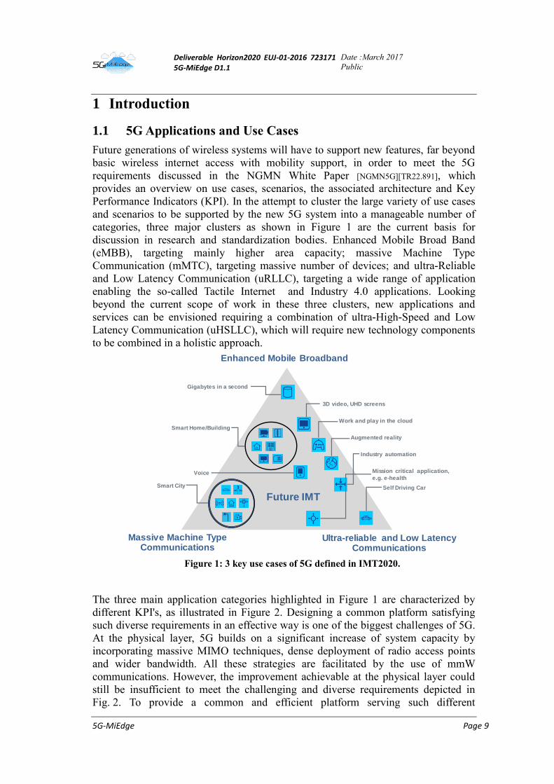
categories, three major clusters as shown in Figure 1 are the current basis for
discussion in research and standardization bodies. Enhanced Mobile Broad Band
(eMBB), targeting mainly higher area capacity; massive Machine Type
Communication (mMTC), targeting massive number of devices; and ultra-Reliable
and Low Latency Communication (uRLLC), targeting a wide range of application
enabling the so-called Tactile Internet and Industry 4.0 applications. Looking
beyond the current scope of work in these three clusters, new applications and
services can be envisioned requiring a combination of ultra-High-Speed and Low
Latency Communication (uHSLLC), which will require new technology components
to be combined in a holistic approach.
Figure 1: 3 key use cases of 5G defined in IMT2020.
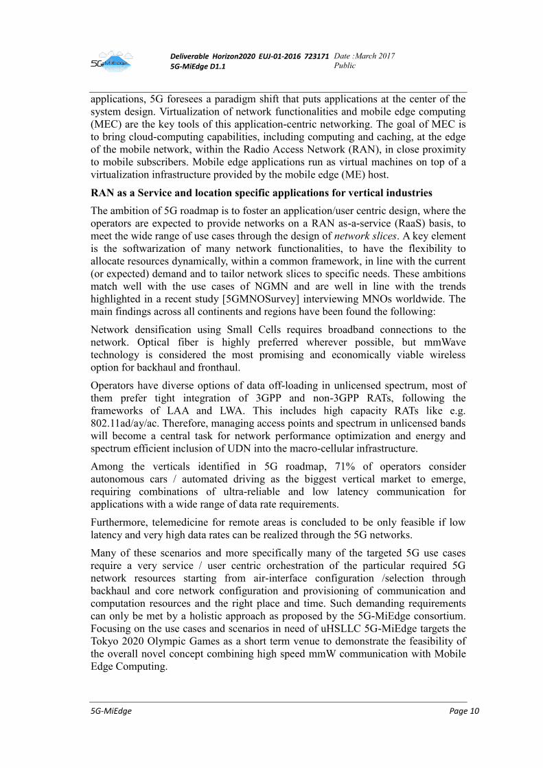
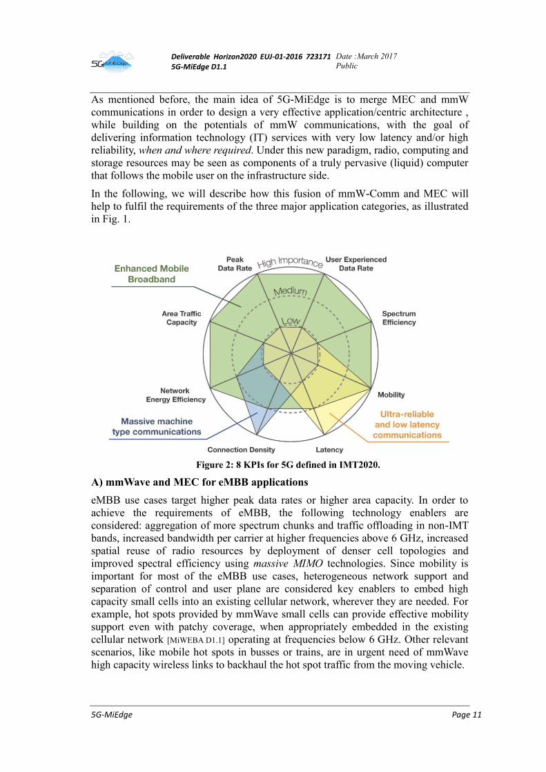
The three main application categories highlighted in Figure 1 are characterized by
different KPI's, as illustrated in Figure 2. Designing a common platform satisfying
such diverse requirements in an effective way is one of the biggest challenges of 5G.
At the physical layer, 5G builds on a significant increase of system capacity by
incorporating massive MIMO techniques, dense deployment of radio access points
and wider bandwidth. All these strategies are facilitated by the use of mmW
communications. However, the improvement achievable at the physical layer could
still be insufficient to meet the challenging and diverse requirements depicted in
Fig. 2. To provide a common and efficient platform serving such different
Enhanced Mobile Broadband
Massive Machine Type Communications
Ultra-reliable and Low Latency Communications
3D video, UHD screens
Smart City
Industry automation
Gigabytes in a second
Self Driving Car
Augmented reality
Smart Home/Building
Work and play in the cloud
Voice Mission critical application,
e.g. e-health
Future IMT
Deliverable Horizon2020 EUJ-01-2016 723171 5G-MiEdge D1.1
Date :March 2017
Public
5G-MiEdge Page 10
applications, 5G foresees a paradigm shift that puts applications at the center of the
system design. Virtualization of network functionalities and mobile edge computing
(MEC) are the key tools of this application-centric networking. The goal of MEC is
to bring cloud-computing capabilities, including computing and caching, at the edge
of the mobile network, within the Radio Access Network (RAN), in close proximity
to mobile subscribers. Mobile edge applications run as virtual machines on top of a
virtualization infrastructure provided by the mobile edge (ME) host.
RAN as a Service and location specific applications for vertical industries
The ambition of 5G roadmap is to foster an application/user centric design, where the
operators are expected to provide networks on a RAN as-a-service (RaaS) basis, to
meet the wide range of use cases through the design of network slices. A key element
is the softwarization of many network functionalities, to have the flexibility to
allocate resources dynamically, within a common framework, in line with the current
(or expected) demand and to tailor network slices to specific needs. These ambitions
match well with the use cases of NGMN and are well in line with the trends
highlighted in a recent study [5GMNOSurvey] interviewing MNOs worldwide. The
main findings across all continents and regions have been found the following:
Network densification using Small Cells requires broadband connections to the
network. Optical fiber is highly preferred wherever possible, but mmWave
technology is considered the most promising and economically viable wireless
option for backhaul and fronthaul.
Operators have diverse options of data off-loading in unlicensed spectrum, most of
them prefer tight integration of 3GPP and non-3GPP RATs, following the
frameworks of LAA and LWA. This includes high capacity RATs like e.g.
802.11ad/ay/ac. Therefore, managing access points and spectrum in unlicensed bands
will become a central task for network performance optimization and energy and
spectrum efficient inclusion of UDN into the macro-cellular infrastructure.
Among the verticals identified in 5G roadmap, 71% of operators consider
autonomous cars / automated driving as the biggest vertical market to emerge,
requiring combinations of ultra-reliable and low latency communication for
applications with a wide range of data rate requirements.
Furthermore, telemedicine for remote areas is concluded to be only feasible if low
latency and very high data rates can be realized through the 5G networks.
Many of these scenarios and more specifically many of the targeted 5G use cases
require a very service / user centric orchestration of the particular required 5G
network resources starting from air-interface configuration /selection through
backhaul and core network configuration and provisioning of communication and
computation resources and the right place and time. Such demanding requirements
can only be met by a holistic approach as proposed by the 5G-MiEdge consortium.
Focusing on the use cases and scenarios in need of uHSLLC 5G-MiEdge targets the
Tokyo 2020 Olympic Games as a short term venue to demonstrate the feasibility of
the overall novel concept combining high speed mmW communication with Mobile
Edge Computing.
Deliverable Horizon2020 EUJ-01-2016 723171 5G-MiEdge D1.1
Date :March 2017
Public
5G-MiEdge Page 11
As mentioned before, the main idea of 5G-MiEdge is to merge MEC and mmW
communications in order to design a very effective application/centric architecture ,
while building on the potentials of mmW communications, with the goal of
delivering information technology (IT) services with very low latency and/or high
reliability, when and where required. Under this new paradigm, radio, computing and
storage resources may be seen as components of a truly pervasive (liquid) computer
that follows the mobile user on the infrastructure side.
In the following, we will describe how this fusion of mmW-Comm and MEC will
help to fulfil the requirements of the three major application categories, as illustrated
in Fig. 1.
Figure 2: 8 KPIs for 5G defined in IMT2020.
A) mmWave and MEC for eMBB applications
eMBB use cases target higher peak data rates or higher area capacity. In order to
achieve the requirements of eMBB, the following technology enablers are
considered: aggregation of more spectrum chunks and traffic offloading in non-IMT
bands, increased bandwidth per carrier at higher frequencies above 6 GHz, increased
spatial reuse of radio resources by deployment of denser cell topologies and
improved spectral efficiency using massive MIMO technologies. Since mobility is
important for most of the eMBB use cases, heterogeneous network support and
separation of control and user plane are considered key enablers to embed high
capacity small cells into an existing cellular network, wherever they are needed. For
example, hot spots provided by mmWave small cells can provide effective mobility
support even with patchy coverage, when appropriately embedded in the existing
cellular network [MiWEBA D1.1] operating at frequencies below 6 GHz. Other relevant
scenarios, like mobile hot spots in busses or trains, are in urgent need of mmWave
high capacity wireless links to backhaul the hot spot traffic from the moving vehicle.

Deliverable Horizon2020 EUJ-01-2016 723171 5G-MiEdge D1.1
Date :March 2017
Public
5G-MiEdge Page 12
Building on the potentials of this advanced physical layer fabric, further
improvements are achievable by introducing MEC technologies. Augmented reality
(AR) is an example of application benefiting from MEC and mmW. These
applications need to be aware of the user’s position and the direction they are facing
through, for example, their camera view. Starting from such information, AR
applications create additional information, in the form of video, sound, etc., and
deliver it to the user in real-time. If the user moves, the information is refreshed and
follows the user. This is a service, which is naturally localized; it requires high
computational capabilities and needs to be delivered with very low delay. Hosting
such AR services on a MEC platform associated to an mmWave Access Point (AP) is
a key strategy to create this computationally demanding, supplementary information
near the mobile user and deliver it satisfying the user experienced latency
requirements.
B) mmW and MEC for URLLC applications
URLLC use cases are mainly covered by the so-called Tactile Internet applications,
e.g. industrial automation or remote control of vehicles over the networks. Such
applications require very stringent KPI fulfillment regarding reliability of successful
packet deliveries or very low end-2-end round trip delays of 1ms, or even less,
requiring concerted latency targeted optimization across all protocol layers. Running
these applications, especially those targeting industrial automation or autonomous
driving, as close as possible to the radio access points is the key strategy to meet the
severe requirements of uRLLC applications in terms of latency and reliability.
Merging MEC with mmW is then the ideal solution to deliver these context-aware
applications requiring ultra-low latency and/or high reliability, as it enables fast
access to MEC services while avoiding the problems associated to latency control
over wide area networks.
In the autonomous driving scenario, the orchestration of multiple MEC servers gives
rise to a distributed car cloud that receives local messages directly from applications
in vehicles and roadside sensors, analyzes them and then propagates hazard warnings
and other latency-sensitive messages to other cars around at extremely low latency.
In the Industry 4.0 scenario, powerful data analytics algorithms, learning the
behavior of production process components and predicting potential failures, can be
implemented very close to the production chain, by local processing of data coming
from multiple sensors. This may be extremely useful to prevent any interruption of
the production cycle and/or to optimize productivity. Furthermore, many of these
industrial local networks can be designed from scratch and optimized for the
purposes they have to serve.
C) mmW and MEC for mMTC
Most of the sensors interconnected in a Smart City scenario have very limited
computation capabilities and energy resources. Computation offloading is then the
key strategy to enable these sensors to supporting sophisticated applications resorting
to nearby computers. This is made possible by proximity access to MEC servers
instantiating virtual machines running the required applications as close as possible
Deliverable Horizon2020 EUJ-01-2016 723171 5G-MiEdge D1.1
Date :March 2017
Public
5G-MiEdge Page 13
to the sensors. Proper orchestration of these virtual machines gives rise to a
distributed control system that overcomes the bottleneck of centralized systems.
In this scenario, merging mmW and MEC is an effective strategy to provide fast
access to IT resources, thus facilitating computation offloading, and to orchestrate
the work of nearby MEC servers through mmW backhaul links.
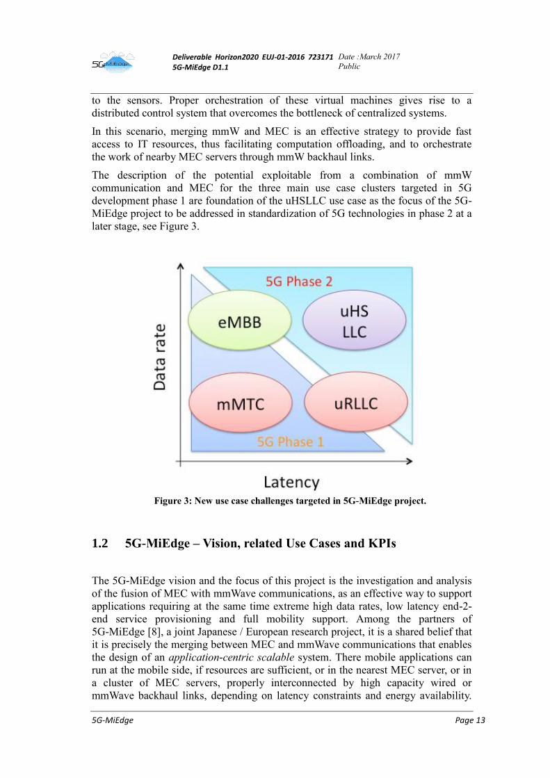
The description of the potential exploitable from a combination of mmW
communication and MEC for the three main use case clusters targeted in 5G
development phase 1 are foundation of the uHSLLC use case as the focus of the 5G-
MiEdge project to be addressed in standardization of 5G technologies in phase 2 at a
later stage, see Figure 3.
Figure 3: New use case challenges targeted in 5G-MiEdge project.
1.2 5G-MiEdge – Vision, related Use Cases and KPIs
The 5G-MiEdge vision and the focus of this project is the investigation and analysis
of the fusion of MEC with mmWave communications, as an effective way to support
applications requiring at the same time extreme high data rates, low latency end-2-
end service provisioning and full mobility support. Among the partners of
5G-MiEdge [8], a joint Japanese / European research project, it is a shared belief that
it is precisely the merging between MEC and mmWave communications that enables
the design of an application-centric scalable system. There mobile applications can
run at the mobile side, if resources are sufficient, or in the nearest MEC server, or in
a cluster of MEC servers, properly interconnected by high capacity wired or
mmWave backhaul links, depending on latency constraints and energy availability.
Deliverable Horizon2020 EUJ-01-2016 723171 5G-MiEdge D1.1
Date :March 2017
Public
5G-MiEdge Page 14
Effective traffic and computation offloading mechanisms are made possible by
enabling fast access to the edge cloud through high capacity mmWave radio access
links. At the same time, proactive strategies like data caching are to be put in place to
meet the demanding end-to-end (E2E) latency requirements of some applications
foreseen in some 5G verticals, such as Industry 4.0 or e-Health. The identification of
scenarios/use cases requiring uHSLLC and benefiting from it is main objective of
this deliverable.
1.2.1 Fusion of mmWave Technology and MEC
The 5G-MiEdge vision builds on two technologies, which are standing up in the
ongoing standardization rush to enable 5G systems by 2020: the use of mmWave for
access and ubiquitous deployment of enhanced Mobile Edge Computing (MEC). The
latter is a very effective way to bring cloud services at the edge of mobile networks,
the former is one of the key enabler of 5G, thanks to its effectiveness in handling
interference and its capability to make possible data rates much higher than any
existing cellular standard. Those technologies well integrate each other into a single
holistic 5G ecosystem, enabling highly efficient network operations, real-time
service delivery, and the ultimate user experience. The main idea is that a fully
effective deployment of MEC is only possible by relying on a very high data rate
radio access and backhauling. mmWave technology is the perfect technology to
enable not only high data rate traffic, but also wireless backhauling, to complement
wired backhauling, when and where necessary. At the same time, a fully effective
exploitation of mmWave technologies can greatly benefit from the distributed
computing capabilities offered by MEC, enabling a joint optimization of
communication, computation and caching resources.
Therefore, the main goal of the 5G-MiEdge project is to design, develop and
demonstrate a highly innovative 5G architecture, with its associated novel signaling
and functionalities, which manages to smartly and smoothly combine mmWave
access/backhauling with MEC. This will enable two of the most important 5G use
cases, namely eMBB services and mission critical URLCC applications (see Figure
1), via cost-efficient Radio Access Networks (RANs), while taking into account
global interoperability issues.
To achieve this goal, 5G-MiEdge proposes a newly defined ultra-lean and inter-
operable control-signaling plane, called liquid RAN C-plane, where liquid stems
from its capability to enabling services and connections able to follow and adapt to
users’ needs, like a liquid adapts to the form of its container. Such a liquid RAN C-
plane is meant to provide ubiquitous liquid allocation of communication and
computation resources, within a user/application-centric perspective. Acquisition of
context information and forecasting of service requests are key steps to enable a
proactive orchestration of radio and computation resources of 5G-MiEdge based 5G
networks.
This set of proposed innovations will bring important advantages and new system
capabilities, as it will:
1) Enable to relax the capacity and latency constraints that characterize the
backhaul of mmWave access technology,
Deliverable Horizon2020 EUJ-01-2016 723171 5G-MiEdge D1.1
Date :March 2017
Public
5G-MiEdge Page 15
2) Limit CAPEX and OPEX for Mobile Network Operators (MNOs) by adapting
available resources to traffic forecast and user context awareness,
3) Provide instantaneous, reliable, and ultra-broadband services by taking
advantage of content prefetching and caching, wide spectrum availability,
insight into the network conditions, and the user proximity to the mmWave
Access Points (APs).
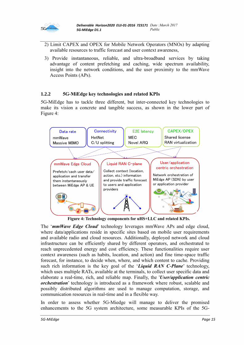
1.2.2 5G-MiEdge key technologies and related KPIs
5G-MiEdge has to tackle three different, but inter-connected key technologies to
make its vision a concrete and tangible success, as shown in the lower part of
Figure 4:
Figure 4: Technology components for uHS+LLC and related KPIs.
The ‘mmWave Edge Cloud’ technology leverages mmWave APs and edge cloud,
where data/applications reside in specific sites based on mobile user requirements
and available radio and cloud resources. Additionally, deployed network and cloud
infrastructure can be efficiently shared by different operators, and orchestrated to
reach unprecedented energy and cost efficiency. These functionalities require user
context awareness (such as habits, location, and action) and fine time-space traffic
forecast, for instance, to decide when, where, and which content to cache. Providing
such rich information is the key goal of the ‘Liquid RAN C-Plane’ technology,
which uses multiple RATs, available at the terminals, to collect user specific data and
elaborate a real-time, rich, and reliable map. Finally, the 'User/application centric
orchestration’ technology is introduced as a framework where robust, scalable and
possibly distributed algorithms are used to manage computation, storage, and
communication resources in real-time and in a flexible way.
In order to assess whether 5G-Miedge will manage to deliver the promised
enhancements to the 5G system architecture, some measurable KPIs of the 5G-
Deliverable Horizon2020 EUJ-01-2016 723171 5G-MiEdge D1.1
Date :March 2017
Public
5G-MiEdge Page 16
MiEdge key technologies are proposed in Table 1. The Technology Readiness Level
(TRL) column is to be read as follows: the number on the left shows the state-of-the-
art at the beginning of the project; the number on the right shows the expected
advancement of the TRL level at the end of the project.
Table 1: 5G MiEdge technologies, KPIs and TRL
Technology Outcome and proposed KPIs to be used for the final evaluation TRL
mmWave Edge Cloud
Outcome: Overall architecture and cross layer functions will be designed, evaluated,
demonstrated, and disseminated.
KPIs: see the 5G MiEdge KPIs in Table 2
1->5
Liquid RAN C-plane Outcome: Definition of control plane and network interfaces.
KPIs: accuracy of the produced resource maps; corresponding control protocols.
2->5
User/Application
centric orchestration
Outcome: algorithms designed and assessed through simulation; selected key
algorithms implemented as a proof of concept.
KPIs: convergence, computational complexity and effectiveness of the proposed
solution will be evaluated.
2->5
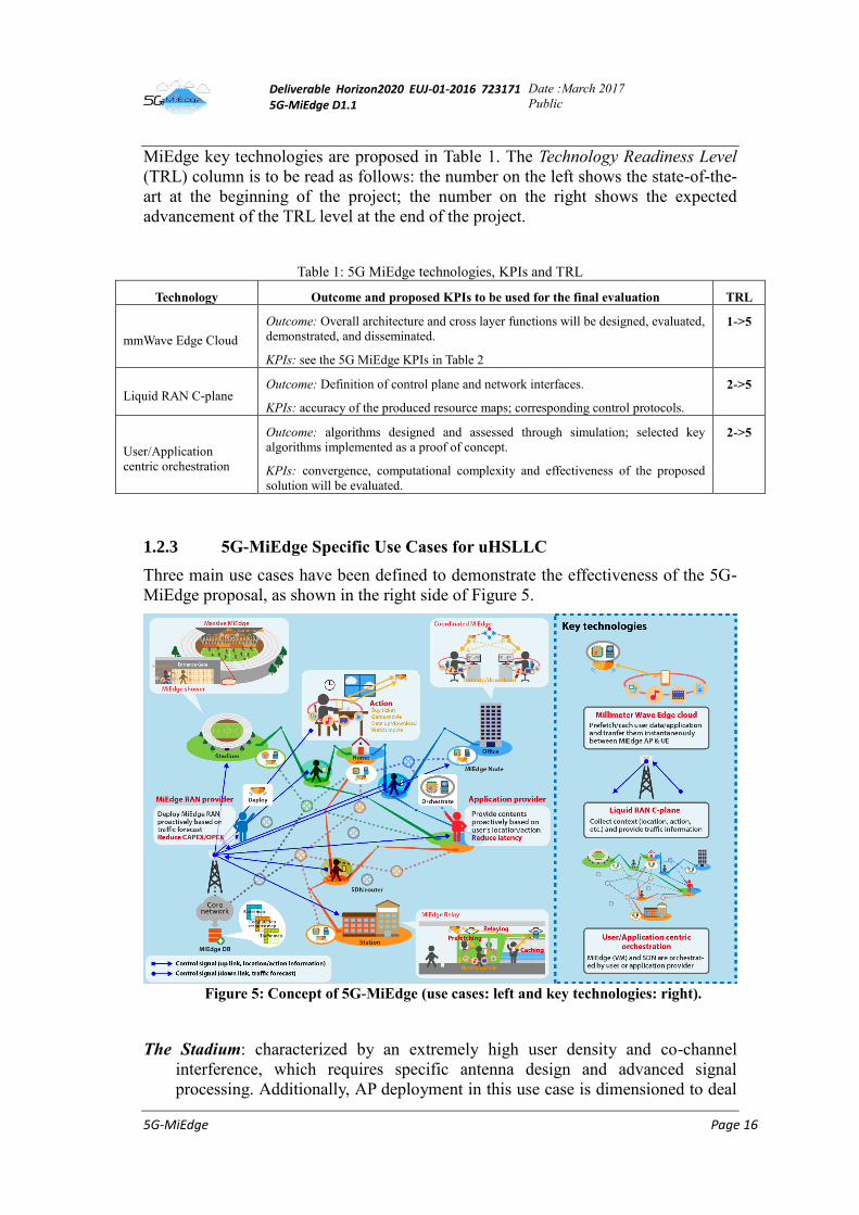
1.2.3 5G-MiEdge Specific Use Cases for uHSLLC
Three main use cases have been defined to demonstrate the effectiveness of the 5G-
MiEdge proposal, as shown in the right side of Figure 5.
Figure 5: Concept of 5G-MiEdge (use cases: left and key technologies: right).
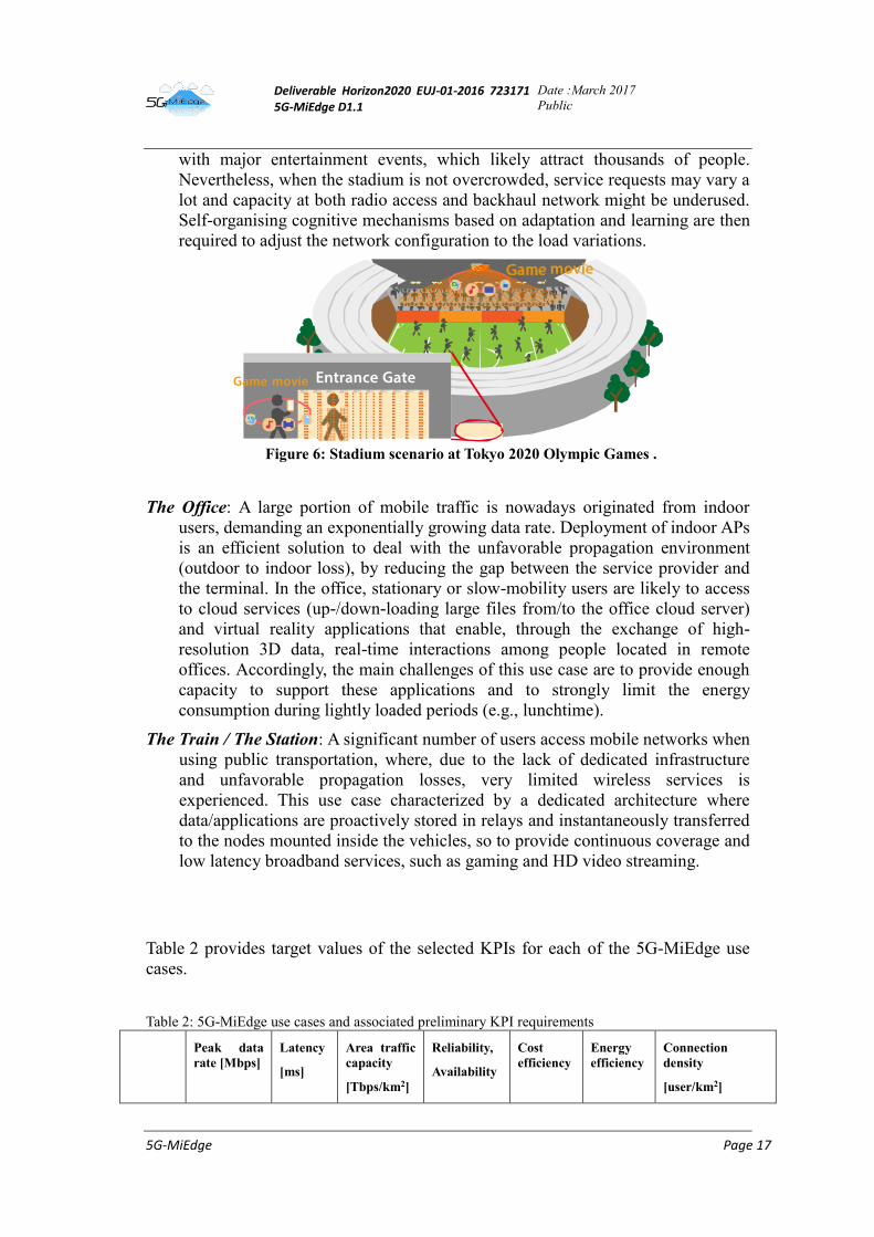
The Stadium: characterized by an extremely high user density and co-channel
interference, which requires specific antenna design and advanced signal
processing. Additionally, AP deployment in this use case is dimensioned to deal
Deliverable Horizon2020 EUJ-01-2016 723171 5G-MiEdge D1.1
Date :March 2017
Public
5G-MiEdge Page 17
with major entertainment events, which likely attract thousands of people.
Nevertheless, when the stadium is not overcrowded, service requests may vary a
lot and capacity at both radio access and backhaul network might be underused.
Self-organising cognitive mechanisms based on adaptation and learning are then
required to adjust the network configuration to the load variations.
Figure 6: Stadium scenario at Tokyo 2020 Olympic Games .
The Office: A large portion of mobile traffic is nowadays originated from indoor
users, demanding an exponentially growing data rate. Deployment of indoor APs
is an efficient solution to deal with the unfavorable propagation environment
(outdoor to indoor loss), by reducing the gap between the service provider and
the terminal. In the office, stationary or slow-mobility users are likely to access
to cloud services (up-/down-loading large files from/to the office cloud server)
and virtual reality applications that enable, through the exchange of high-
resolution 3D data, real-time interactions among people located in remote
offices. Accordingly, the main challenges of this use case are to provide enough
capacity to support these applications and to strongly limit the energy
consumption during lightly loaded periods (e.g., lunchtime).
The Train / The Station: A significant number of users access mobile networks when
using public transportation, where, due to the lack of dedicated infrastructure
and unfavorable propagation losses, very limited wireless services is
experienced. This use case characterized by a dedicated architecture where
data/applications are proactively stored in relays and instantaneously transferred
to the nodes mounted inside the vehicles, so to provide continuous coverage and
low latency broadband services, such as gaming and HD video streaming.
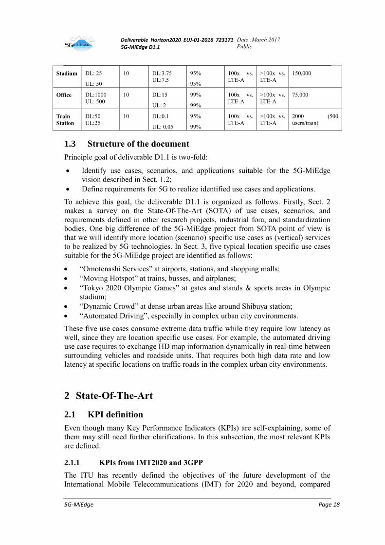
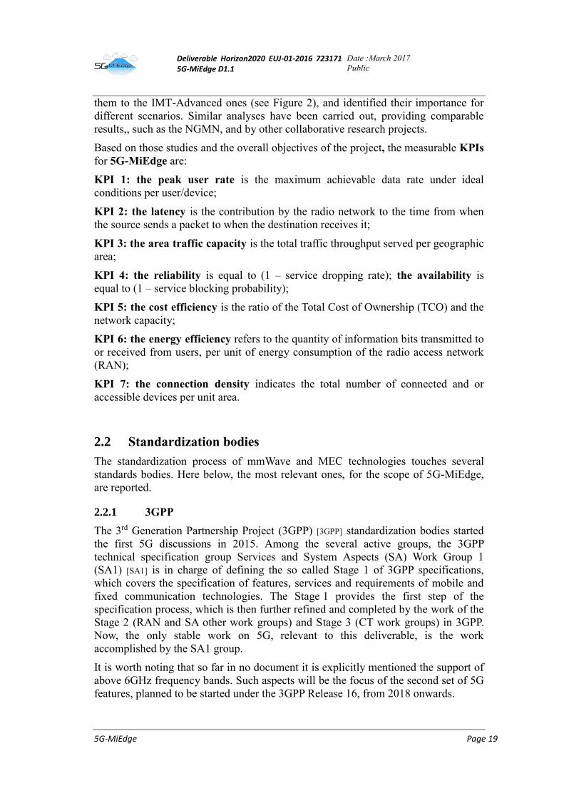
Table 2 provides target values of the selected KPIs for each of the 5G-MiEdge use
cases.
Table 2: 5G-MiEdge use cases and associated preliminary KPI requirements
Peak data
rate [Mbps]
Latency
[ms]
Area traffic
capacity
[Tbps/km2]
Reliability,
Availability
Cost
efficiency
Energy
efficiency
Connection
density
[user/km2]
Deliverable Horizon2020 EUJ-01-2016 723171 5G-MiEdge D1.1
Date :March 2017
Public
5G-MiEdge Page 18
Stadium DL: 25
UL: 50
10 DL:3.75
UL:7.5
95%
95%
100x vs.
LTE-A
>100x vs.
LTE-A
150,000
Office DL:1000
UL: 500
10 DL:15
UL: 2
99%
99%
100x vs.
LTE-A
>100x vs.
LTE-A
75,000
Train
Station
DL:50
UL:25
10 DL:0.1
UL: 0.05
95%
99%
100x vs.
LTE-A
>100x vs.
LTE-A
2000 (500
users/train)
1.3 Structure of the document
Principle goal of deliverable D1.1 is two-fold:
Identify use cases, scenarios, and applications suitable for the 5G-MiEdge
vision described in Sect. 1.2;
Define requirements for 5G to realize identified use cases and applications.
To achieve this goal, the deliverable D1.1 is organized as follows. Firstly, Sect. 2
makes a survey on the State-Of-The-Art (SOTA) of use cases, scenarios, and
requirements defined in other research projects, industrial fora, and standardization
bodies. One big difference of the 5G-MiEdge project from SOTA point of view is
that we will identify more location (scenario) specific use cases as (vertical) services
to be realized by 5G technologies. In Sect. 3, five typical location specific use cases
suitable for the 5G-MiEdge project are identified as follows:
“Omotenashi Services” at airports, stations, and shopping malls;
“Moving Hotspot” at trains, busses, and airplanes;
“Tokyo 2020 Olympic Games” at gates and stands & sports areas in Olympic
stadium;
“Dynamic Crowd” at dense urban areas like around Shibuya station;
“Automated Driving”, especially in complex urban city environments.
These five use cases consume extreme data traffic while they require low latency as
well, since they are location specific use cases. For example, the automated driving
use case requires to exchange HD map information dynamically in real-time between
surrounding vehicles and roadside units. That requires both high data rate and low
latency at specific locations on traffic roads in the complex urban city environments.
2 State-Of-The-Art
2.1 KPI definition
Even though many Key Performance Indicators (KPIs) are self-explaining, some of
them may still need further clarifications. In this subsection, the most relevant KPIs
are defined.
2.1.1 KPIs from IMT2020 and 3GPP
The ITU has recently defined the objectives of the future development of the
International Mobile Telecommunications (IMT) for 2020 and beyond, compared
Deliverable Horizon2020 EUJ-01-2016 723171 5G-MiEdge D1.1
Date :March 2017
Public
5G-MiEdge Page 19
them to the IMT-Advanced ones (see Figure 2), and identified their importance for
different scenarios. Similar analyses have been carried out, providing comparable
results,, such as the NGMN, and by other collaborative research projects.
Based on those studies and the overall objectives of the project, the measurable KPIs
for 5G-MiEdge are:
KPI 1: the peak user rate is the maximum achievable data rate under ideal
conditions per user/device;
KPI 2: the latency is the contribution by the radio network to the time from when
the source sends a packet to when the destination receives it;
KPI 3: the area traffic capacity is the total traffic throughput served per geographic
area;
KPI 4: the reliability is equal to (1 – service dropping rate); the availability is
equal to (1 – service blocking probability);
KPI 5: the cost efficiency is the ratio of the Total Cost of Ownership (TCO) and the
network capacity;
KPI 6: the energy efficiency refers to the quantity of information bits transmitted to
or received from users, per unit of energy consumption of the radio access network
(RAN);
KPI 7: the connection density indicates the total number of connected and or
accessible devices per unit area.
2.2 Standardization bodies
The standardization process of mmWave and MEC technologies touches several
standards bodies. Here below, the most relevant ones, for the scope of 5G-MiEdge,
are reported.
2.2.1 3GPP
The 3rd Generation Partnership Project (3GPP) [3GPP] standardization bodies started
the first 5G discussions in 2015. Among the several active groups, the 3GPP
technical specification group Services and System Aspects (SA) Work Group 1
(SA1) [SA1] is in charge of defining the so called Stage 1 of 3GPP specifications,
which covers the specification of features, services and requirements of mobile and
fixed communication technologies. The Stage 1 provides the first step of the
specification process, which is then further refined and completed by the work of the
Stage 2 (RAN and SA other work groups) and Stage 3 (CT work groups) in 3GPP.
Now, the only stable work on 5G, relevant to this deliverable, is the work
accomplished by the SA1 group.
It is worth noting that so far in no document it is explicitly mentioned the support of
above 6GHz frequency bands. Such aspects will be the focus of the second set of 5G
features, planned to be started under the 3GPP Release 16, from 2018 onwards.
Deliverable Horizon2020 EUJ-01-2016 723171 5G-MiEdge D1.1
Date :March 2017
Public
5G-MiEdge Page 20
2.2.1.1 Use cases as defined by SA1
In 2015, SA1 started under the 3GPP Release 14 the work on the first set of 5G
features with the creation of the Feasibility Study “on New Services and Markets
Technology Enablers (SMARTER)”. The scope was to “identify the market segments
and verticals whose needs 3GPP should focus on meeting, and to identify groups of
related use cases and requirements that the 3GPP eco-system would need to support
in the future”. The work reached a milestone with the creation of the Technical
Report TR 22.891 [TR22.891] “Feasibility Study on New Services and Markets
Technology Enablers; Stage 1”, which contains more than 70 different use cases,
categorized in four different groups:
- massive Internet of Things,
- Critical Communications,
- enhanced Mobile Broadband,
- Network Operation.
Each one of those groups spun the creation of a related new Technical Report with
the same title, all approved at the 3GPP SA#72 meeting held in June 2016 in Busan,
Korea. The four TRs are summarized in the table below.
Table 3 SMARTER TRs for 5G use cases and requirements specification
TR 22.861:
FS_SMARTER –
massive Internet of
Things
Massive Internet of Things focuses on use cases with massive number of
devices (e.g., sensors and wearables). This group of use cases is
particularly relevant to the new vertical services, such as smart home and
city, smart utilities, e-Health, and smart wearables.
TR 22.862:
FS_SMARTER –
Critical
Communications
The main areas where improvements are needed for Critical
Communications are latency, reliability, and availability to enable, for
example, industrial control applications and tactile Internet. These
requirements can be met with an improved radio interface, optimized
architecture, and dedicated core and radio resources.
TR 22.863:
FS_SMARTER –
enhanced Mobile
Broadband
Enhanced Mobile Broadband includes a number of different use case
families related to higher data rates, higher density, deployment and
coverage, higher user mobility, devices with highly variable user data
rates, fixed mobile convergence, and small-cell deployments.
TR 22.864:
FS_SMARTER –
Network Operation
The use case group Network Operation addresses the functional system
requirements, including aspects such as: flexible functions and capabilities,
new value creation, migration and interworking, optimizations and
enhancements, and security.
SA1 consolidated under the 3GPP Release 15 the four TRs into the a single
document, the first Technical Specification TS 22.261 [TS22.261] for 5G requirements
“Service requirements for the 5G system; Stage 1”, which was very recently
approved in the SA#75 meeting held in March 2017 in Dubrovnik, Croatia. The TS
provides the first normative text in 5G, i.e. the Stage 1 requirements for next
generation mobile telecommunications, guiding the future work of the Stage 2 (RAN
and SA) and Stage 3 (CT) work groups in 3GPP.
Deliverable Horizon2020 EUJ-01-2016 723171 5G-MiEdge D1.1
Date :March 2017
Public
5G-MiEdge Page 21
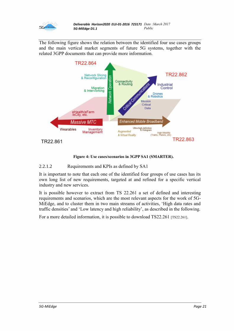
The following figure shows the relation between the identified four use cases groups
and the main vertical market segments of future 5G systems, together with the
related 3GPP documents that can provide more information.
Figure 4: Use cases/scenarios in 3GPP SA1 (SMARTER).
2.2.1.2 Requirements and KPIs as defined by SA1
It is important to note that each one of the identified four groups of use cases has its
own long list of new requirements, targeted at and refined for a specific vertical
industry and new services.
It is possible however to extract from TS 22.261 a set of defined and interesting
requirements and scenarios, which are the most relevant aspects for the work of 5G-
MiEdge, and to cluster them in two main streams of activities, ‘High data rates and
traffic densities’ and ‘Low latency and high reliability’, as described in the following.
For a more detailed information, it is possible to download TS22.261 [TS22.261].
Deliverable Horizon2020 EUJ-01-2016 723171 5G-MiEdge D1.1
Date :March 2017
Public
5G-MiEdge Page 22
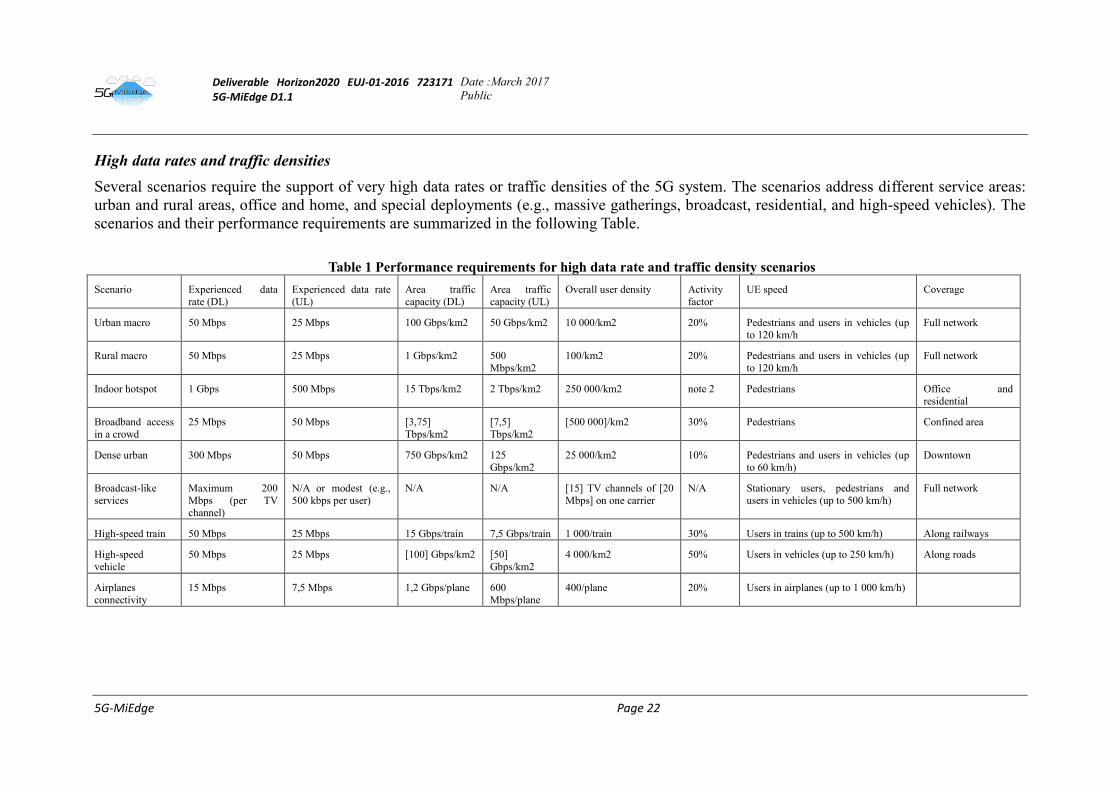
High data rates and traffic densities
Several scenarios require the support of very high data rates or traffic densities of the 5G system. The scenarios address different service areas:
urban and rural areas, office and home, and special deployments (e.g., massive gatherings, broadcast, residential, and high-speed vehicles). The
scenarios and their performance requirements are summarized in the following Table.
Table 1 Performance requirements for high data rate and traffic density scenarios
Scenario Experienced data
rate (DL)
Experienced data rate
(UL)
Area traffic
capacity (DL)
Area traffic
capacity (UL)
Overall user density Activity
factor
UE speed Coverage
Urban macro 50 Mbps 25 Mbps 100 Gbps/km2 50 Gbps/km2 10 000/km2 20% Pedestrians and users in vehicles (up
to 120 km/h
Full network
Rural macro 50 Mbps 25 Mbps 1 Gbps/km2 500
Mbps/km2
100/km2 20% Pedestrians and users in vehicles (up
to 120 km/h
Full network
Indoor hotspot 1 Gbps 500 Mbps 15 Tbps/km2 2 Tbps/km2 250 000/km2 note 2 Pedestrians Office and
residential
Broadband access
in a crowd
25 Mbps 50 Mbps [3,75]
Tbps/km2
[7,5]
Tbps/km2
[500 000]/km2 30% Pedestrians Confined area
Dense urban 300 Mbps 50 Mbps 750 Gbps/km2 125
Gbps/km2
25 000/km2 10% Pedestrians and users in vehicles (up
to 60 km/h)
Downtown
Broadcast-like
services
Maximum 200
Mbps (per TV
channel)
N/A or modest (e.g.,
500 kbps per user)
N/A N/A [15] TV channels of [20
Mbps] on one carrier
N/A Stationary users, pedestrians and
users in vehicles (up to 500 km/h)
Full network
High-speed train 50 Mbps 25 Mbps 15 Gbps/train 7,5 Gbps/train 1 000/train 30% Users in trains (up to 500 km/h) Along railways
High-speed
vehicle
50 Mbps 25 Mbps [100] Gbps/km2 [50]
Gbps/km2
4 000/km2 50% Users in vehicles (up to 250 km/h) Along roads
Airplanes
connectivity
15 Mbps 7,5 Mbps 1,2 Gbps/plane 600
Mbps/plane
400/plane 20% Users in airplanes (up to 1 000 km/h)
Deliverable Horizon2020 EUJ-01-2016 723171 5G-MiEdge D1.1
Date :March 2017
Public
5G-MiEdge Page 23
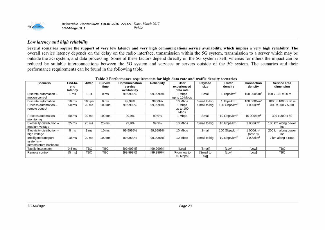
Low latency and high reliability
Several scenarios require the support of very low latency and very high communications service availability, which implies a very high reliability. The
overall service latency depends on the delay on the radio interface, transmission within the 5G system, transmission to a server which may be
outside the 5G system, and data processing. Some of these factors depend directly on the 5G system itself, whereas for others the impact can be
reduced by suitable interconnections between the 5G system and services or servers outside of the 5G system. The scenarios and their
performance requirements can be found in the following table.
Table 2 Performance requirements for high data rate and traffic density scenarios Scenario End-to-
end latency
Jitter Survival time
Communication service
availability
Reliability
User experienced
data rate
Payload size
Traffic density
Connection density
Service area dimension
Discrete automation – motion control
1 ms 1 µs 0 ms 99,9999% 99,9999% 1 Mbps up to 10 Mbps
Small 1 Tbps/km2 100 000/km2 100 x 100 x 30 m
Discrete automation 10 ms 100 µs 0 ms 99,99% 99,99% 10 Mbps Small to big 1 Tbps/km2 100 000/km2 1000 x 1000 x 30 m
Process automation – remote control
50 ms 20 ms 100 ms 99,9999% 99,9999% 1 Mbps up to 100
Mbps
Small to big 100 Gbps/km2 1 000/km2 300 x 300 x 50 m
Process automation ‒ monitoring
50 ms 20 ms 100 ms 99,9% 99,9% 1 Mbps Small 10 Gbps/km2 10 000/km2 300 x 300 x 50
Electricity distribution – medium voltage
25 ms 25 ms 25 ms 99,9% 99,9% 10 Mbps Small to big 10 Gbps/km2 1 000/km2 100 km along power line
Electricity distribution – high voltage
5 ms 1 ms 10 ms 99,9999% 99,9999% 10 Mbps Small 100 Gbps/km2 1 000/km2
(note 9) 200 km along power
line
Intelligent transport systems – infrastructure backhaul
10 ms
20 ms 100 ms 99,9999% 99,9999% 10 Mbps Small to big 10 Gbps/km2 1 000/km2 2 km along a road
Tactile interaction 0,5 ms TBC TBC [99,999%] [99,999%] [Low] [Small] [Low] [Low] TBC
Remote control [5 ms] TBC TBC [99,999%] [99,999%] [From low to 10 Mbps]
[Small to big]
[Low] [Low] TBC
Deliverable Horizon2020 EUJ-01-2016 723171 5G-MiEdge D1.1
Date :March 2017
Public
5G-MiEdge Page 24
2.2.2 ETSI MEC
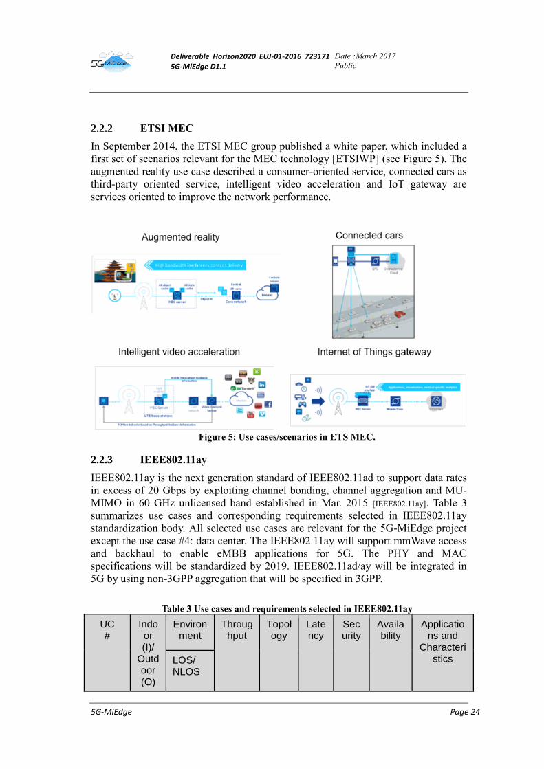
In September 2014, the ETSI MEC group published a white paper, which included a
first set of scenarios relevant for the MEC technology [ETSIWP] (see Figure 5). The
augmented reality use case described a consumer-oriented service, connected cars as
third-party oriented service, intelligent video acceleration and IoT gateway are
services oriented to improve the network performance.
Figure 5: Use cases/scenarios in ETS MEC.
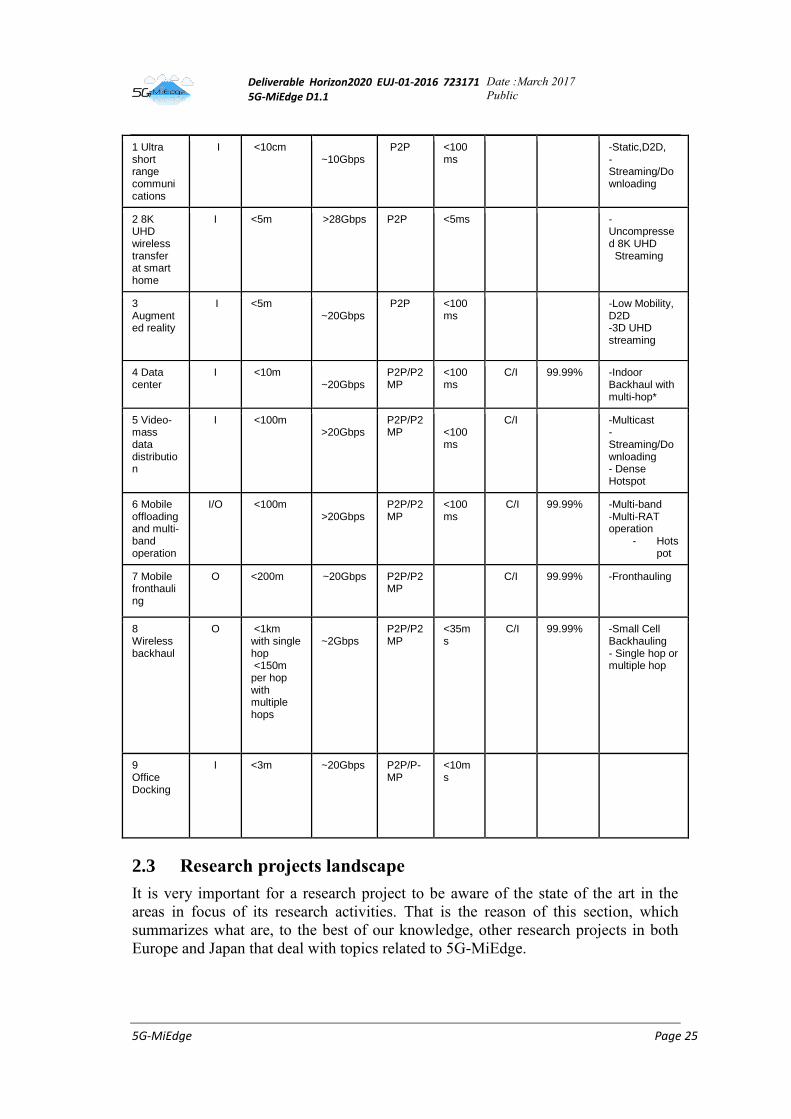
2.2.3 IEEE802.11ay
IEEE802.11ay is the next generation standard of IEEE802.11ad to support data rates
in excess of 20 Gbps by exploiting channel bonding, channel aggregation and MU-
MIMO in 60 GHz unlicensed band established in Mar. 2015 [IEEE802.11ay]. Table 3
summarizes use cases and corresponding requirements selected in IEEE802.11ay
standardization body. All selected use cases are relevant for the 5G-MiEdge project
except the use case #4: data center. The IEEE802.11ay will support mmWave access
and backhaul to enable eMBB applications for 5G. The PHY and MAC
specifications will be standardized by 2019. IEEE802.11ad/ay will be integrated in
5G by using non-3GPP aggregation that will be specified in 3GPP.
Table 3 Use cases and requirements selected in IEEE802.11ay
UC #
Indoor (I)/
Outdoor (O)
Environment
Throughput
Topology
Latency
Security
Availability
Applications and
Characteristics LOS/
NLOS
Deliverable Horizon2020 EUJ-01-2016 723171 5G-MiEdge D1.1
Date :March 2017
Public
5G-MiEdge Page 25
1 Ultra short range communications
I <10cm ~10Gbps
P2P <100ms
-Static,D2D, -Streaming/Downloading
2 8K UHD wireless transfer at smart home
I <5m >28Gbps P2P <5ms
-Uncompressed 8K UHD Streaming
3 Augmented reality
I <5m ~20Gbps
P2P <100ms
-Low Mobility, D2D -3D UHD streaming
4 Data center
I <10m ~20Gbps
P2P/P2MP
<100ms
C/I 99.99% -Indoor Backhaul with multi-hop*
5 Video-mass data distribution
I <100m >20Gbps
P2P/P2MP
<100ms
C/I
-Multicast -Streaming/Downloading - Dense Hotspot
6 Mobile offloading and multi-band operation
I/O <100m >20Gbps
P2P/P2MP
<100ms
C/I 99.99% -Multi-band -Multi-RAT operation
- Hotspot
7 Mobile fronthauling
O <200m ~20Gbps P2P/P2MP
C/I 99.99% -Fronthauling
8 Wireless backhaul
O <1km with single hop <150m per hop with multiple hops
~2Gbps
P2P/P2MP
<35ms
C/I 99.99% -Small Cell Backhauling - Single hop or multiple hop
9 Office Docking
I <3m ~20Gbps P2P/P-MP
<10ms
2.3 Research projects landscape
It is very important for a research project to be aware of the state of the art in the
areas in focus of its research activities. That is the reason of this section, which
summarizes what are, to the best of our knowledge, other research projects in both
Europe and Japan that deal with topics related to 5G-MiEdge.
Deliverable Horizon2020 EUJ-01-2016 723171 5G-MiEdge D1.1
Date :March 2017
Public
5G-MiEdge Page 26
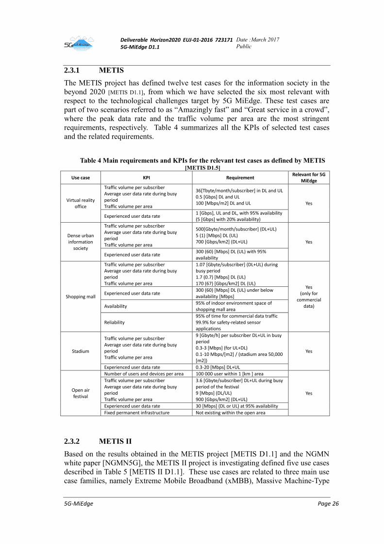
2.3.1 METIS
The METIS project has defined twelve test cases for the information society in the
beyond 2020 [METIS D1.1], from which we have selected the six most relevant with
respect to the technological challenges target by 5G MiEdge. These test cases are
part of two scenarios referred to as “Amazingly fast” and “Great service in a crowd”,
where the peak data rate and the traffic volume per area are the most stringent
requirements, respectively. Table 4 summarizes all the KPIs of selected test cases
and the related requirements.
Table 4 Main requirements and KPIs for the relevant test cases as defined by METIS [METIS D1.5]
Use case KPI Requirement Relevant for 5G
MiEdge
Virtual reality office
Traffic volume per subscriber Average user data rate during busy period Traffic volume per area
36[Tbyte/month/subscriber] in DL and UL 0.5 [Gbps] DL and UL 100 [Mbps/m2] DL and UL Yes
Experienced user data rate 1 [Gbps], UL and DL, with 95% availability (5 [Gbps] with 20% availability)
Dense urban information
society
Traffic volume per subscriber Average user data rate during busy period Traffic volume per area
500[Gbyte/month/subscriber] (DL+UL) 5 (1) [Mbps] DL (UL) 700 [Gbps/km2] (DL+UL) Yes
Experienced user data rate 300 (60) [Mbps] DL (UL) with 95% availability
Shopping mall
Traffic volume per subscriber Average user data rate during busy period Traffic volume per area
1.07 [Gbyte/subscriber] (DL+UL) during busy period 1.7 (0.7) [Mbps] DL (UL) 170 (67) [Gbps/km2] DL (UL)
Yes (only for
commercial data)
Experienced user data rate 300 (60) [Mbps] DL (UL) under below availability [Mbps]
Availability 95% of indoor environment space of shopping mall area
Reliability 95% of time for commercial data traffic 99.9% for safety-related sensor applications
Stadium
Traffic volume per subscriber Average user data rate during busy period Traffic volume per area
9 [Gbyte/h] per subscriber DL+UL in busy period 0.3-3 [Mbps] (for UL+DL) 0.1-10 Mbps/[m2] / (stadium area 50,000 [m2])
Yes
Experienced user data rate 0.3-20 [Mbps] DL+UL
Open air festival
Number of users and devices per area 100 000 user within 1 [km ] area
Yes
Traffic volume per subscriber Average user data rate during busy period Traffic volume per area
3.6 [Gbyte/subscriber] DL+UL during busy period of the festival 9 [Mbps] (DL/UL) 900 [Gbps/km2] (DL+UL)
Experienced user data rate 30 [Mbps] (DL or UL) at 95% availability
Fixed permanent infrastructure Not existing within the open area
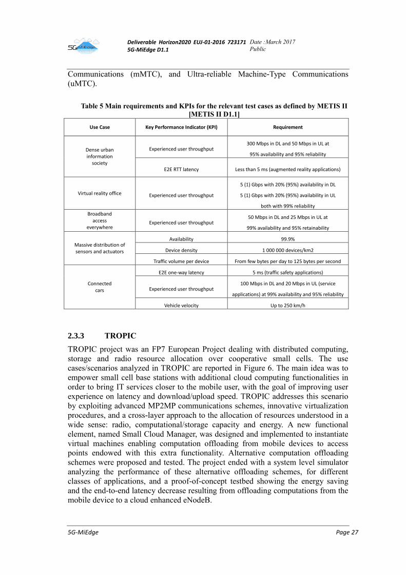
2.3.2 METIS II
Based on the results obtained in the METIS project [METIS D1.1] and the NGMN
white paper [NGMN5G], the METIS II project is investigating defined five use cases
described in Table 5 [METIS II D1.1]. These use cases are related to three main use
case families, namely Extreme Mobile Broadband (xMBB), Massive Machine-Type
Deliverable Horizon2020 EUJ-01-2016 723171 5G-MiEdge D1.1
Date :March 2017
Public
5G-MiEdge Page 27
Communications (mMTC), and Ultra-reliable Machine-Type Communications
(uMTC).
Table 5 Main requirements and KPIs for the relevant test cases as defined by METIS II
[METIS II D1.1]
Use Case Key Performance Indicator (KPI) Requirement
Dense urban information
society
Experienced user throughput 300 Mbps in DL and 50 Mbps in UL at
95% availability and 95% reliability
E2E RTT latency Less than 5 ms (augmented reality applications)
Virtual reality office Experienced user throughput
5 (1) Gbps with 20% (95%) availability in DL
5 (1) Gbps with 20% (95%) availability in UL
both with 99% reliability
Broadband access
everywhere Experienced user throughput
50 Mbps in DL and 25 Mbps in UL at
99% availability and 95% retainability
Massive distribution of sensors and actuators
Availability 99.9%
Device density 1 000 000 devices/km2
Traffic volume per device From few bytes per day to 125 bytes per second
Connected cars
E2E one-way latency 5 ms (traffic safety applications)
Experienced user throughput 100 Mbps in DL and 20 Mbps in UL (service
applications) at 99% availability and 95% reliability
Vehicle velocity Up to 250 km/h
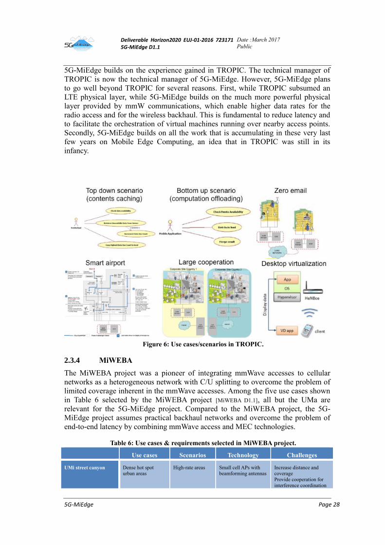
2.3.3 TROPIC
TROPIC project was an FP7 European Project dealing with distributed computing,
storage and radio resource allocation over cooperative small cells. The use
cases/scenarios analyzed in TROPIC are reported in Figure 6. The main idea was to
empower small cell base stations with additional cloud computing functionalities in
order to bring IT services closer to the mobile user, with the goal of improving user
experience on latency and download/upload speed. TROPIC addresses this scenario
by exploiting advanced MP2MP communications schemes, innovative virtualization
procedures, and a cross-layer approach to the allocation of resources understood in a
wide sense: radio, computational/storage capacity and energy. A new functional
element, named Small Cloud Manager, was designed and implemented to instantiate
virtual machines enabling computation offloading from mobile devices to access
points endowed with this extra functionality. Alternative computation offloading
schemes were proposed and tested. The project ended with a system level simulator
analyzing the performance of these alternative offloading schemes, for different
classes of applications, and a proof-of-concept testbed showing the energy saving
and the end-to-end latency decrease resulting from offloading computations from the
mobile device to a cloud enhanced eNodeB.
Deliverable Horizon2020 EUJ-01-2016 723171 5G-MiEdge D1.1
Date :March 2017
Public
5G-MiEdge Page 28
5G-MiEdge builds on the experience gained in TROPIC. The technical manager of
TROPIC is now the technical manager of 5G-MiEdge. However, 5G-MiEdge plans
to go well beyond TROPIC for several reasons. First, while TROPIC subsumed an
LTE physical layer, while 5G-MiEdge builds on the much more powerful physical
layer provided by mmW communications, which enable higher data rates for the
radio access and for the wireless backhaul. This is fundamental to reduce latency and
to facilitate the orchestration of virtual machines running over nearby access points.
Secondly, 5G-MiEdge builds on all the work that is accumulating in these very last
few years on Mobile Edge Computing, an idea that in TROPIC was still in its
infancy.
Figure 6: Use cases/scenarios in TROPIC.
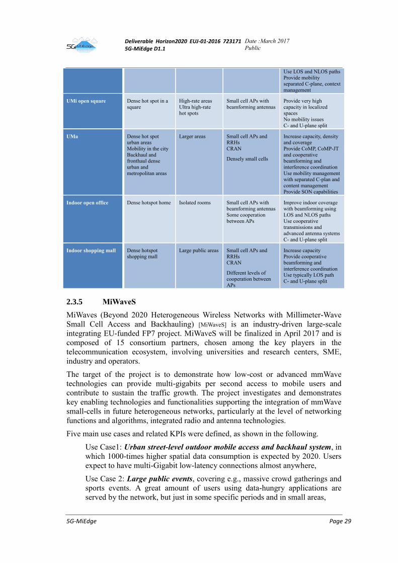
2.3.4 MiWEBA
The MiWEBA project was a pioneer of integrating mmWave accesses to cellular
networks as a heterogeneous network with C/U splitting to overcome the problem of
limited coverage inherent in the mmWave accesses. Among the five use cases shown
in Table 6 selected by the MiWEBA project [MiWEBA D1.1], all but the UMa are
relevant for the 5G-MiEdge project. Compared to the MiWEBA project, the 5G-
MiEdge project assumes practical backhaul networks and overcome the problem of
end-to-end latency by combining mmWave access and MEC technologies.
Table 6: Use cases & requirements selected in MiWEBA project.
Use cases Scenarios Technology Challenges
UMi street canyon Dense hot spot urban areas
High-rate areas Small cell APs with beamforming antennas
Increase distance and coverage
Provide cooperation for
interference coordination
Deliverable Horizon2020 EUJ-01-2016 723171 5G-MiEdge D1.1
Date :March 2017
Public
5G-MiEdge Page 29
Use LOS and NLOS paths
Provide mobility separated C-plane, context
management
UMi open square Dense hot spot in a
square
High-rate areas
Ultra high-rate hot spots
Small cell APs with
beamforming antennas
Provide very high
capacity in localized spaces
No mobility issues
C- and U-plane split
UMa Dense hot spot urban areas
Mobility in the city
Backhaul and fronthaul dense
urban and
metropolitan areas
Larger areas Small cell APs and RRHs
CRAN
Densely small cells
Increase capacity, density and coverage
Provide CoMP, CoMP-JT
and cooperative beamforming and
interference coordination
Use mobility management
with separated C-plan and
content management
Provide SON capabilities
Indoor open office Dense hotspot home Isolated rooms Small cell APs with beamforming antennas
Some cooperation
between APs
Improve indoor coverage with beamforming using
LOS and NLOS paths
Use cooperative transmissions and
advanced antenna systems
C- and U-plane split
Indoor shopping mall Dense hotspot shopping mall
Large public areas Small cell APs and RRHs
CRAN
Different levels of cooperation between
APs
Increase capacity Provide cooperative
beamforming and
interference coordination Use typically LOS path
C- and U-plane split
2.3.5 MiWaveS
MiWaves (Beyond 2020 Heterogeneous Wireless Networks with Millimeter-Wave
Small Cell Access and Backhauling) [MiWaveS] is an industry-driven large-scale
integrating EU-funded FP7 project. MiWaveS will be finalized in April 2017 and is
composed of 15 consortium partners, chosen among the key players in the
telecommunication ecosystem, involving universities and research centers, SME,
industry and operators.
The target of the project is to demonstrate how low-cost or advanced mmWave
technologies can provide multi-gigabits per second access to mobile users and
contribute to sustain the traffic growth. The project investigates and demonstrates
key enabling technologies and functionalities supporting the integration of mmWave
small-cells in future heterogeneous networks, particularly at the level of networking
functions and algorithms, integrated radio and antenna technologies.
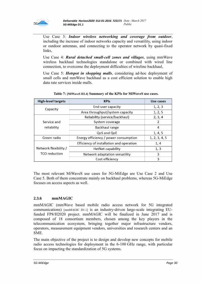
Five main use cases and related KPIs were defined, as shown in the following.
Use Case1: Urban street-level outdoor mobile access and backhaul system, in
which 1000-times higher spatial data consumption is expected by 2020. Users
expect to have multi-Gigabit low-latency connections almost anywhere,
Use Case 2: Large public events, covering e.g., massive crowd gatherings and
sports events. A great amount of users using data-hungry applications are
served by the network, but just in some specific periods and in small areas,
Deliverable Horizon2020 EUJ-01-2016 723171 5G-MiEdge D1.1
Date :March 2017
Public
5G-MiEdge Page 30
Use Case 3: Indoor wireless networking and coverage from outdoor,
including the increase of indoor networks capacity and versatility, using indoor
or outdoor antennas, and connecting to the operator network by quasi-fixed
links,
Use Case 4: Rural detached small-cell zones and villages, using mmWave
wireless backhaul technologies standalone or combined with wired line
connection, to overcome the deployment difficulties of wireline backhaul,
Use Case 5: Hotspot in shopping malls, considering ad-hoc deployment of
small cells and mmWave backhaul as a cost efficient solution to enable high
data rate services inside malls.
Table 7: [MiWaveS D2.4] Summary of the KPIs for MiWaveS use cases.
The most relevant MiWaveS use cases for 5G-MiEdge are Use Case 2 and Use
Case 5. Both of them concentrate mainly on backhaul problems, whereas 5G-MiEdge
focuses on access aspects as well.
2.3.6 mmMAGIC
mmMAGIC (mmWave based mobile radio access network for 5G integrated
communications) [mmMAGIC D1.1] is an industry-driven large-scale integrating EU-
funded FP8/H2020 project. mmMAGIC will be finalized in June 2017 and is
composed of 18 consortium members, chosen among the key players in the
telecommunication ecosystem, bringing together major infrastructure vendors,
operators, measurement equipment vendors, universities and research centers and an
SME.
The main objective of the project is to design and develop new concepts for mobile
radio access technologies for deployment in the 6-100 GHz range, with particular
focus on impacting the standardization of 5G systems.
Deliverable Horizon2020 EUJ-01-2016 723171 5G-MiEdge D1.1
Date :March 2017
Public
5G-MiEdge Page 31
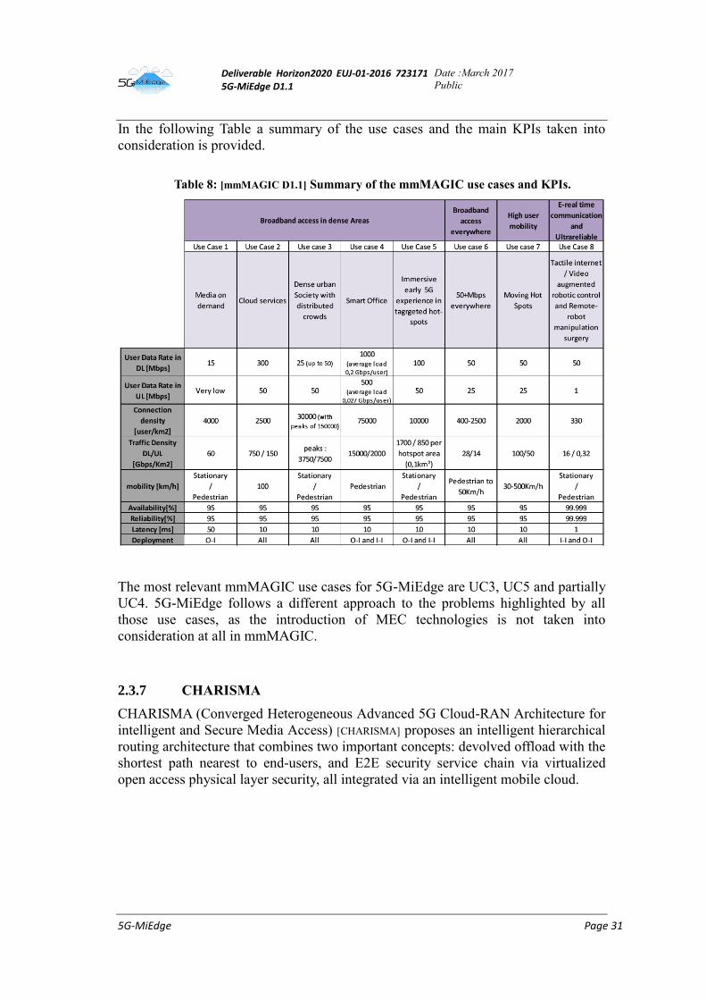
In the following Table a summary of the use cases and the main KPIs taken into
consideration is provided.
Table 8: [mmMAGIC D1.1] Summary of the mmMAGIC use cases and KPIs.
The most relevant mmMAGIC use cases for 5G-MiEdge are UC3, UC5 and partially
UC4. 5G-MiEdge follows a different approach to the problems highlighted by all
those use cases, as the introduction of MEC technologies is not taken into
consideration at all in mmMAGIC.
2.3.7 CHARISMA
CHARISMA (Converged Heterogeneous Advanced 5G Cloud-RAN Architecture for
intelligent and Secure Media Access) [CHARISMA] proposes an intelligent hierarchical
routing architecture that combines two important concepts: devolved offload with the
shortest path nearest to end-users, and E2E security service chain via virtualized
open access physical layer security, all integrated via an intelligent mobile cloud.
Deliverable Horizon2020 EUJ-01-2016 723171 5G-MiEdge D1.1
Date :March 2017
Public
5G-MiEdge Page 32
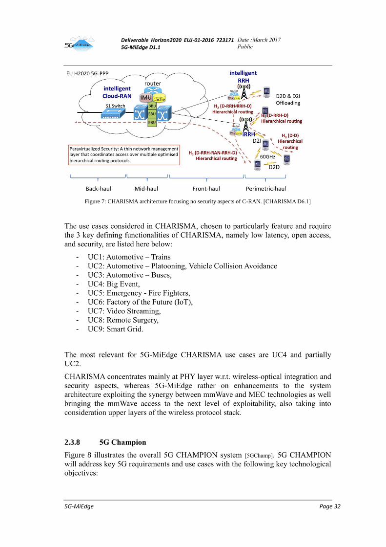
Figure 7: CHARISMA architecture focusing no security aspects of C-RAN. [CHARISMA D6.1]
The use cases considered in CHARISMA, chosen to particularly feature and require
the 3 key defining functionalities of CHARISMA, namely low latency, open access,
and security, are listed here below:
- UC1: Automotive – Trains
- UC2: Automotive – Platooning, Vehicle Collision Avoidance
- UC3: Automotive – Buses,
- UC4: Big Event,
- UC5: Emergency - Fire Fighters,
- UC6: Factory of the Future (IoT),
- UC7: Video Streaming,
- UC8: Remote Surgery,
- UC9: Smart Grid.
The most relevant for 5G-MiEdge CHARISMA use cases are UC4 and partially
UC2.
CHARISMA concentrates mainly at PHY layer w.r.t. wireless-optical integration and
security aspects, whereas 5G-MiEdge rather on enhancements to the system
architecture exploiting the synergy between mmWave and MEC technologies as well
bringing the mmWave access to the next level of exploitability, also taking into
consideration upper layers of the wireless protocol stack.
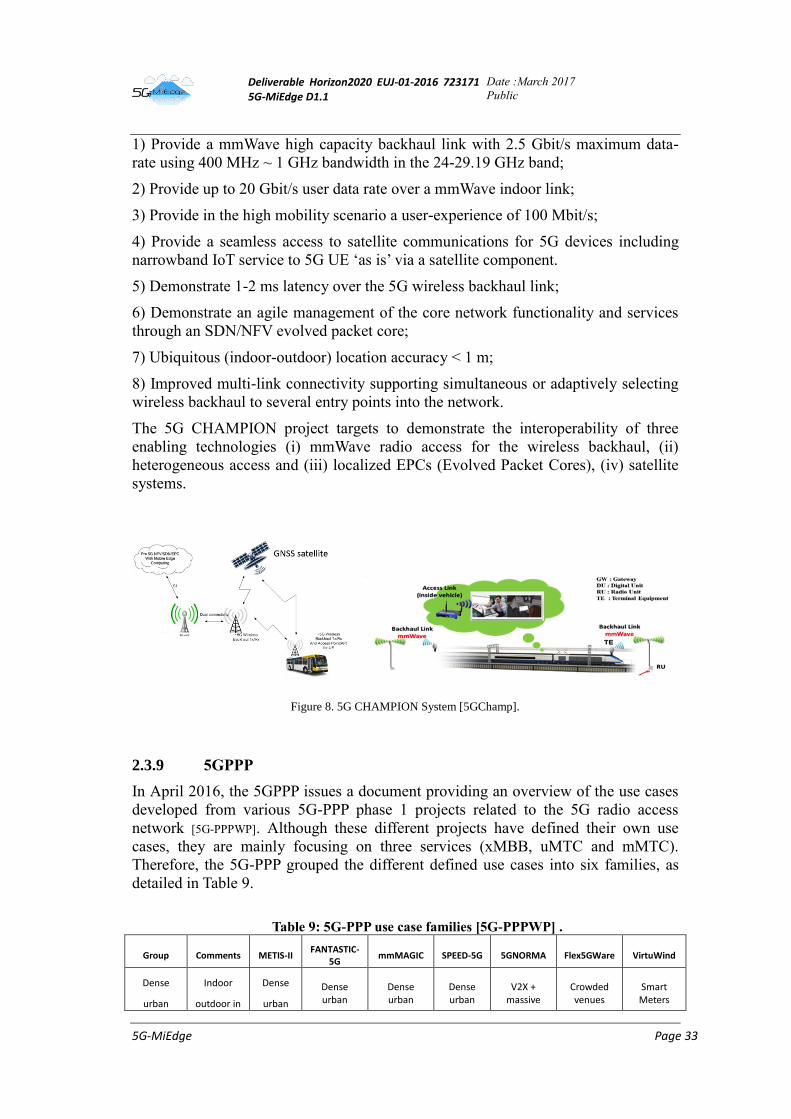
2.3.8 5G Champion
Figure 8 illustrates the overall 5G CHAMPION system [5GChamp]. 5G CHAMPION
will address key 5G requirements and use cases with the following key technological
objectives:
Deliverable Horizon2020 EUJ-01-2016 723171 5G-MiEdge D1.1
Date :March 2017
Public
5G-MiEdge Page 33
1) Provide a mmWave high capacity backhaul link with 2.5 Gbit/s maximum data-
rate using 400 MHz ~ 1 GHz bandwidth in the 24-29.19 GHz band;
2) Provide up to 20 Gbit/s user data rate over a mmWave indoor link;
3) Provide in the high mobility scenario a user-experience of 100 Mbit/s;
4) Provide a seamless access to satellite communications for 5G devices including
narrowband IoT service to 5G UE ‘as is’ via a satellite component.
5) Demonstrate 1-2 ms latency over the 5G wireless backhaul link;
6) Demonstrate an agile management of the core network functionality and services
through an SDN/NFV evolved packet core;
7) Ubiquitous (indoor-outdoor) location accuracy < 1 m;
8) Improved multi-link connectivity supporting simultaneous or adaptively selecting
wireless backhaul to several entry points into the network.
The 5G CHAMPION project targets to demonstrate the interoperability of three
enabling technologies (i) mmWave radio access for the wireless backhaul, (ii)
heterogeneous access and (iii) localized EPCs (Evolved Packet Cores), (iv) satellite
systems.
Figure 8. 5G CHAMPION System [5GChamp].
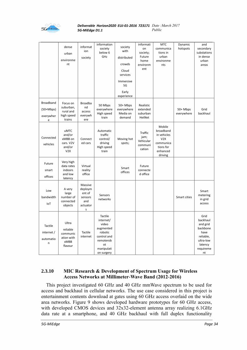
2.3.9 5GPPP
In April 2016, the 5GPPP issues a document providing an overview of the use cases
developed from various 5G-PPP phase 1 projects related to the 5G radio access
network [5G-PPPWP]. Although these different projects have defined their own use
cases, they are mainly focusing on three services (xMBB, uMTC and mMTC).
Therefore, the 5G-PPP grouped the different defined use cases into six families, as
detailed in Table 9.
Table 9: 5G-PPP use case families [5G-PPPWP] .
Group Comments METIS-II FANTASTIC-
5G mmMAGIC SPEED-5G 5GNORMA Flex5GWare VirtuWind
Dense
urban
Indoor
outdoor in
Dense
urban
Dense urban
Dense urban
Dense urban
V2X + massive
Crowded venues
Smart Meters
Deliverable Horizon2020 EUJ-01-2016 723171 5G-MiEdge D1.1
Date :March 2017
Public
5G-MiEdge Page 34
dense
urban
environment
information
society
information society below 6
GHz
society with
distributed
crowds
Cloud services
Immersive 5G
Early experience
information
society; Future home
environment
MTC communica
tions in urban
environments
Dynamic hotspots
and secondary substations
in dense urban areas
Broadband
(50+Mbps)
everywhere
Focus on suburban, rural and
high speed trains
Broadband
access everywh
ere
50 Mbps everywhere High speed
train
50+ Mbps everywhere
Media on demand
Realistic extended suburban
HetNet
50+ Mbps
everywhere Grid
backhaul
Connected
vehicles
uMTC and/or
xMBB on cars. V2V
and/or V2X
Connected cars
Automatic traffic
control/ driving
High speed train
Moving hot spots;
Traffic jam;
Vehicular communi
cation
Mobile broadband in vehicles
V2X communica
tions for enhanced
driving
Future
smart
offices
Very high data rates
indoors and low latency
Virtual reality office
Smart offices
Future connected office
Low
bandwidth
IoT
A very large
number of connected
objects
Massive deploym
ent of sensors
and actuator
s
Sensors networks
Smart cities
Smart metering
in grid access
Tactile
internet /
automation
Ultra
reliable communication with
xMBB flavour
Tactile internet
Tactile internet/
video augmented
robotic control and remoterob
ot manipulation surgery
Grid backhaul and grid
backbone have
reliable, ultra-low latency
requirement
2.3.10 MIC Research & Development of Spectrum Usage for Wireless
Access Networks at Millimeter-Wave Band (2012-2016)
This project investigated 60 GHz and 40 GHz mmWave spectrum to be used for
access and backhaul in cellular networks. The use case considered in this project is
entertainment contents download at gates using 60 GHz access overlaid on the wide
area networks. Figure 9 shows developed hardware prototypes for 60 GHz access,
with developed CMOS devices and 32x32-element antenna array realizing 6.1GHz
data rate at a smartphone, and 40 GHz backhaul with full duplex functionality

Deliverable Horizon2020 EUJ-01-2016 723171 5G-MiEdge D1.1
Date :March 2017
Public
5G-MiEdge Page 35
[ATN16]. Figure 10 shows a PoC system of 60 GHz and 40 GHz integrated
heterogeneous networks demonstrated in Tokyo Institute of Technology in Mar.
2016. The PoC demonstrated seamless services of video data download over the
mmWave integrated heterogeneous networks. This prototype hardware will be
integrated into 5G-MiEdge project to be combined with MEC technologies. [ATN16]
(a) 60 GHz UE.
(b) 60 GHz BS.
(c) 40 GHz full duplex
backhaul.
Figure 9: Developed hardware prototypes for 60 GHz access and 40 GHz backhaul.
Figure 10: PoC system of mmWave integrated heterogeneous networks.
2.3.11 MIC: Research & development of advanced multiplexing and
interference management technologies for millimeter-wave frequency
bands
The project aimed to develop technologies required for point-to-multipoint
millimeter-wave access (Figure 11) that is applicable for public deployment use-case
scenarios such as in stores and train stations. The project also developed the
technology for co-existence of millimeter-wave systems. The project carried out
system simulations, experimental demonstrations (Figure 12) and standardization
activities (mainly in IEEE 802.11TGay), and successfully developed interference
management technologies for efficient use of the 60 GHz frequency band.
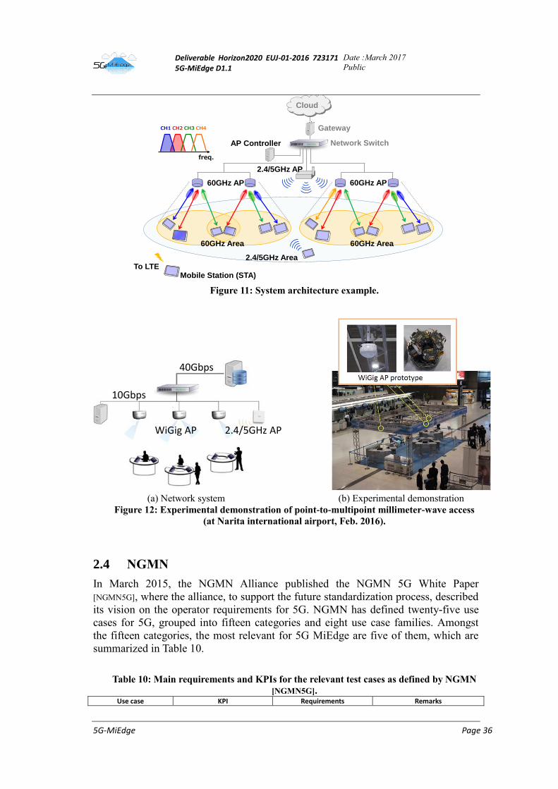
Deliverable Horizon2020 EUJ-01-2016 723171 5G-MiEdge D1.1
Date :March 2017
Public
5G-MiEdge Page 36
Figure 11: System architecture example.
(a) Network system (b) Experimental demonstration Figure 12: Experimental demonstration of point-to-multipoint millimeter-wave access
(at Narita international airport, Feb. 2016).
2.4 NGMN
In March 2015, the NGMN Alliance published the NGMN 5G White Paper
[NGMN5G], where the alliance, to support the future standardization process, described
its vision on the operator requirements for 5G. NGMN has defined twenty-five use
cases for 5G, grouped into fifteen categories and eight use case families. Amongst
the fifteen categories, the most relevant for 5G MiEdge are five of them, which are
summarized in Table 10.
Table 10: Main requirements and KPIs for the relevant test cases as defined by NGMN
[NGMN5G]. Use case KPI Requirements Remarks
Cloud
60GHz AP
freq.
CH1 CH2 CH3 CH4
60GHz AP
2.4/5GHz AP
Gateway
Network Switch
60GHz Area
2.4/5GHz Area
60GHz Area
AP Controller
Mobile Station (STA)To LTE
40Gbps
10Gbps
WiGig AP 2.4/5GHz AP
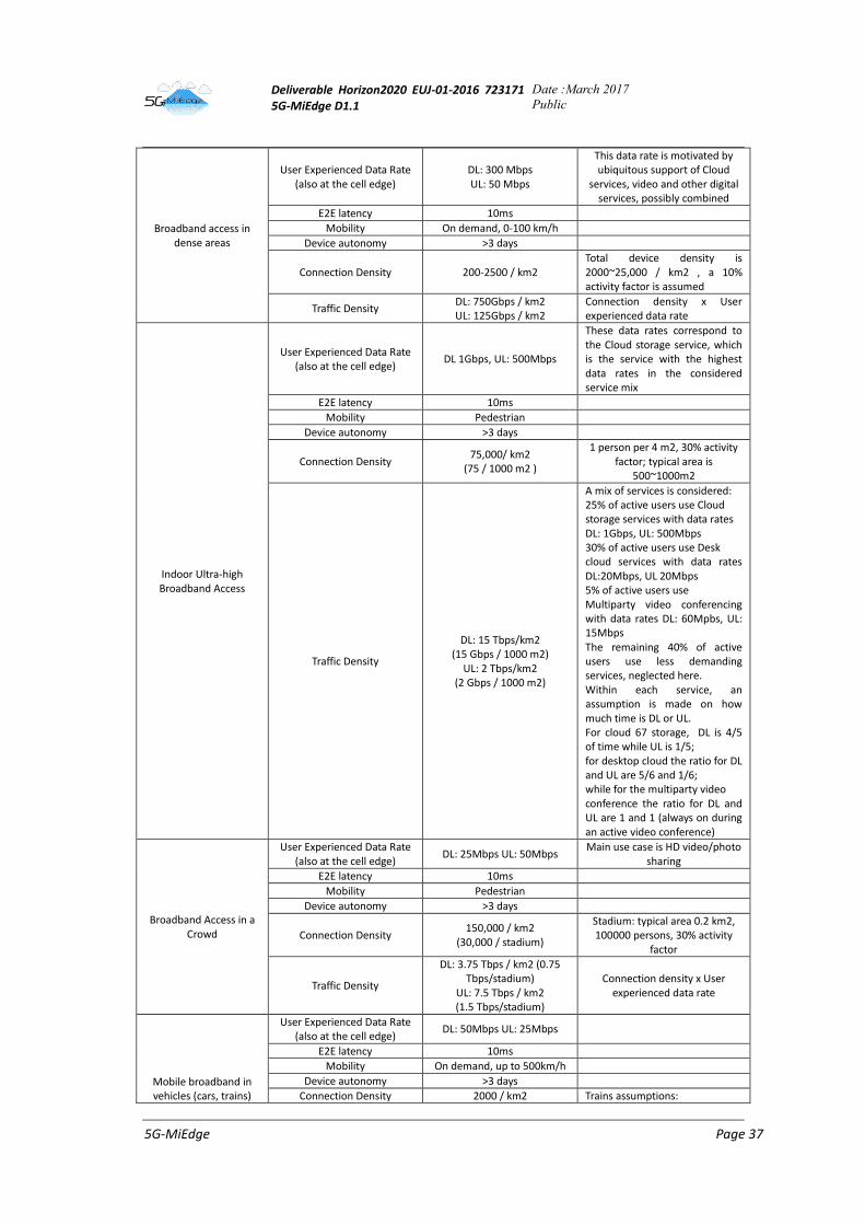
Deliverable Horizon2020 EUJ-01-2016 723171 5G-MiEdge D1.1
Date :March 2017
Public
5G-MiEdge Page 37
Broadband access in dense areas
User Experienced Data Rate (also at the cell edge)
DL: 300 Mbps UL: 50 Mbps
This data rate is motivated by ubiquitous support of Cloud
services, video and other digital services, possibly combined
E2E latency 10ms
Mobility On demand, 0-100 km/h
Device autonomy >3 days
Connection Density 200-2500 / km2 Total device density is 2000~25,000 / km2 , a 10% activity factor is assumed
Traffic Density DL: 750Gbps / km2 UL: 125Gbps / km2
Connection density x User experienced data rate
Indoor Ultra-high Broadband Access
User Experienced Data Rate (also at the cell edge)
DL 1Gbps, UL: 500Mbps
These data rates correspond to the Cloud storage service, which is the service with the highest data rates in the considered service mix
E2E latency 10ms
Mobility Pedestrian
Device autonomy >3 days
Connection Density 75,000/ km2
(75 / 1000 m2 )
1 person per 4 m2, 30% activity factor; typical area is
500~1000m2
Traffic Density
DL: 15 Tbps/km2 (15 Gbps / 1000 m2)
UL: 2 Tbps/km2 (2 Gbps / 1000 m2)
A mix of services is considered: 25% of active users use Cloud storage services with data rates DL: 1Gbps, UL: 500Mbps 30% of active users use Desk cloud services with data rates DL:20Mbps, UL 20Mbps 5% of active users use Multiparty video conferencing with data rates DL: 60Mpbs, UL: 15Mbps The remaining 40% of active users use less demanding services, neglected here. Within each service, an assumption is made on how much time is DL or UL. For cloud 67 storage, DL is 4/5 of time while UL is 1/5; for desktop cloud the ratio for DL and UL are 5/6 and 1/6; while for the multiparty video conference the ratio for DL and UL are 1 and 1 (always on during an active video conference)
Broadband Access in a Crowd
User Experienced Data Rate (also at the cell edge)
DL: 25Mbps UL: 50Mbps Main use case is HD video/photo
sharing
E2E latency 10ms
Mobility Pedestrian
Device autonomy >3 days
Connection Density 150,000 / km2
(30,000 / stadium)
Stadium: typical area 0.2 km2, 100000 persons, 30% activity
factor
Traffic Density
DL: 3.75 Tbps / km2 (0.75 Tbps/stadium)
UL: 7.5 Tbps / km2 (1.5 Tbps/stadium)
Connection density x User experienced data rate
Mobile broadband in vehicles (cars, trains)
User Experienced Data Rate (also at the cell edge)
DL: 50Mbps UL: 25Mbps
E2E latency 10ms
Mobility On demand, up to 500km/h
Device autonomy >3 days
Connection Density 2000 / km2 Trains assumptions:
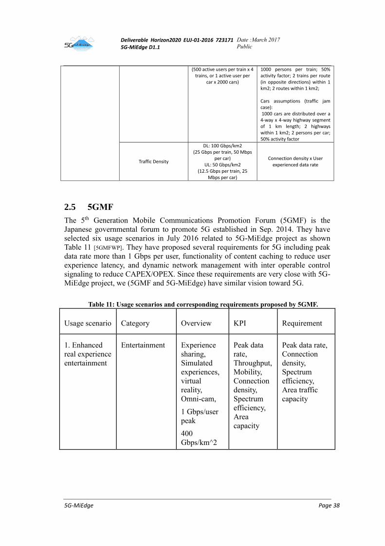
Deliverable Horizon2020 EUJ-01-2016 723171 5G-MiEdge D1.1
Date :March 2017
Public
5G-MiEdge Page 38
(500 active users per train x 4 trains, or 1 active user per
car x 2000 cars)
1000 persons per train; 50% activity factor; 2 trains per route (in opposite directions) within 1 km2; 2 routes within 1 km2;
Cars assumptions (traffic jam case): 1000 cars are distributed over a 4-way x 4-way highway segment of 1 km length; 2 highways within 1 km2; 2 persons per car; 50% activity factor
Traffic Density
DL: 100 Gbps/km2 (25 Gbps per train, 50 Mbps
per car) UL: 50 Gbps/km2
(12.5 Gbps per train, 25 Mbps per car)
Connection density x User experienced data rate
2.5 5GMF
The 5th Generation Mobile Communications Promotion Forum (5GMF) is the
Japanese governmental forum to promote 5G established in Sep. 2014. They have
selected six usage scenarios in July 2016 related to 5G-MiEdge project as shown
Table 11 [5GMFWP]. They have proposed several requirements for 5G including peak
data rate more than 1 Gbps per user, functionality of content caching to reduce user
experience latency, and dynamic network management with inter operable control
signaling to reduce CAPEX/OPEX. Since these requirements are very close with 5G-
MiEdge project, we (5GMF and 5G-MiEdge) have similar vision toward 5G.
Table 11: Usage scenarios and corresponding requirements proposed by 5GMF.
Usage scenario Category Overview KPI Requirement
1. Enhanced
real experience
entertainment
Entertainment Experience
sharing,
Simulated
experiences,
virtual
reality,
Omni-cam,
1 Gbps/user
peak
400
Gbps/km^2
Peak data
rate,
Throughput,
Mobility,
Connection
density,
Spectrum
efficiency,
Area
capacity
Peak data rate,
Connection
density,
Spectrum
efficiency,
Area traffic
capacity
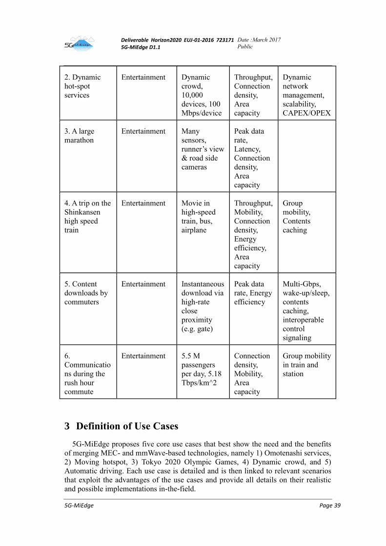
Deliverable Horizon2020 EUJ-01-2016 723171 5G-MiEdge D1.1
Date :March 2017
Public
5G-MiEdge Page 39
2. Dynamic
hot-spot
services
Entertainment Dynamic
crowd,
10,000
devices, 100
Mbps/device
Throughput,
Connection
density,
Area
capacity
Dynamic
network
management,
scalability,
CAPEX/OPEX
3. A large
marathon
Entertainment Many
sensors,
runner’s view
& road side
cameras
Peak data
rate,
Latency,
Connection
density,
Area
capacity
4. A trip on the
Shinkansen
high speed
train
Entertainment Movie in
high-speed
train, bus,
airplane
Throughput,
Mobility,
Connection
density,
Energy
efficiency,
Area
capacity
Group
mobility,
Contents
caching
5. Content
downloads by
commuters
Entertainment Instantaneous
download via
high-rate
close
proximity
(e.g. gate)
Peak data
rate, Energy
efficiency
Multi-Gbps,
wake-up/sleep,
contents
caching,
interoperable
control
signaling
6.
Communicatio
ns during the
rush hour
commute
Entertainment 5.5 M
passengers
per day, 5.18
Tbps/km^2
Connection
density,
Mobility,
Area
capacity
Group mobility
in train and
station
3 Definition of Use Cases
5G-MiEdge proposes five core use cases that best show the need and the benefits
of merging MEC- and mmWave-based technologies, namely 1) Omotenashi services,
2) Moving hotspot, 3) Tokyo 2020 Olympic Games, 4) Dynamic crowd, and 5)
Automatic driving. Each use case is detailed and is then linked to relevant scenarios
that exploit the advantages of the use cases and provide all details on their realistic
and possible implementations in-the-field.
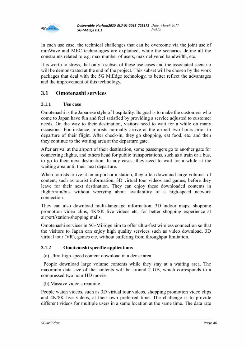
Deliverable Horizon2020 EUJ-01-2016 723171 5G-MiEdge D1.1
Date :March 2017
Public
5G-MiEdge Page 40
In each use case, the technical challenges that can be overcome via the joint use of
mmWave and MEC technologies are explained, while the scenarios define all the
constraints related to e.g. max number of users, max delivered bandwidth, etc.
It is worth to stress, that only a subset of these use cases and the associated scenario
will be demonstrated at the end of the project. This subset will be chosen by the work
packages that deal with the 5G MiEdge technology, to better reflect the advantages
and the improvement of this technology.
3.1 Omotenashi services
3.1.1 Use case
Omotenashi is the Japanese style of hospitality. Its goal is to make the customers who
come to Japan have fun and feel satisfied by providing a service adjusted to customer
needs. On the way to their destination, visitors need to wait for a while on many
occasions. For instance, tourists normally arrive at the airport two hours prior to
departure of their flight. After check-in, they go shopping, eat food, etc. and then
they continue to the waiting area at the departure gate.
After arrival at the airport of their destination, some passengers go to another gate for
connecting flights, and others head for public transportations, such as a train or a bus,
to go to their next destination. In any cases, they need to wait for a while at the
waiting area until their next departure.
When tourists arrive at an airport or a station, they often download large volumes of
content, such as tourist information, 3D virtual tour videos and games, before they
leave for their next destination. They can enjoy these downloaded contents in
flight/train/bus without worrying about availability of a high-speed network
connection.
They can also download multi-language information, 3D indoor maps, shopping
promotion video clips, 4K/8K live videos etc. for better shopping experience at
airport/station/shopping malls.
Omotenashi services in 5G-MiEdge aim to offer ultra-fast wireless connection so that
the visitors to Japan can enjoy high quality services such as video download, 3D
virtual tour (VR), games etc. without suffering from throughput limitation.
3.1.2 Omotenashi specific applications
(a) Ultra-high-speed content download in a dense area
People download large volume contents while they stay at a waiting area. The
maximum data size of the contents will be around 2 GB, which corresponds to a
compressed two hour HD movie.
(b) Massive video streaming
People watch videos, such as 3D virtual tour videos, shopping promotion video clips
and 4K/8K live videos, at their own preferred time. The challenge is to provide
different videos for multiple users in a same location at the same time. The data rate
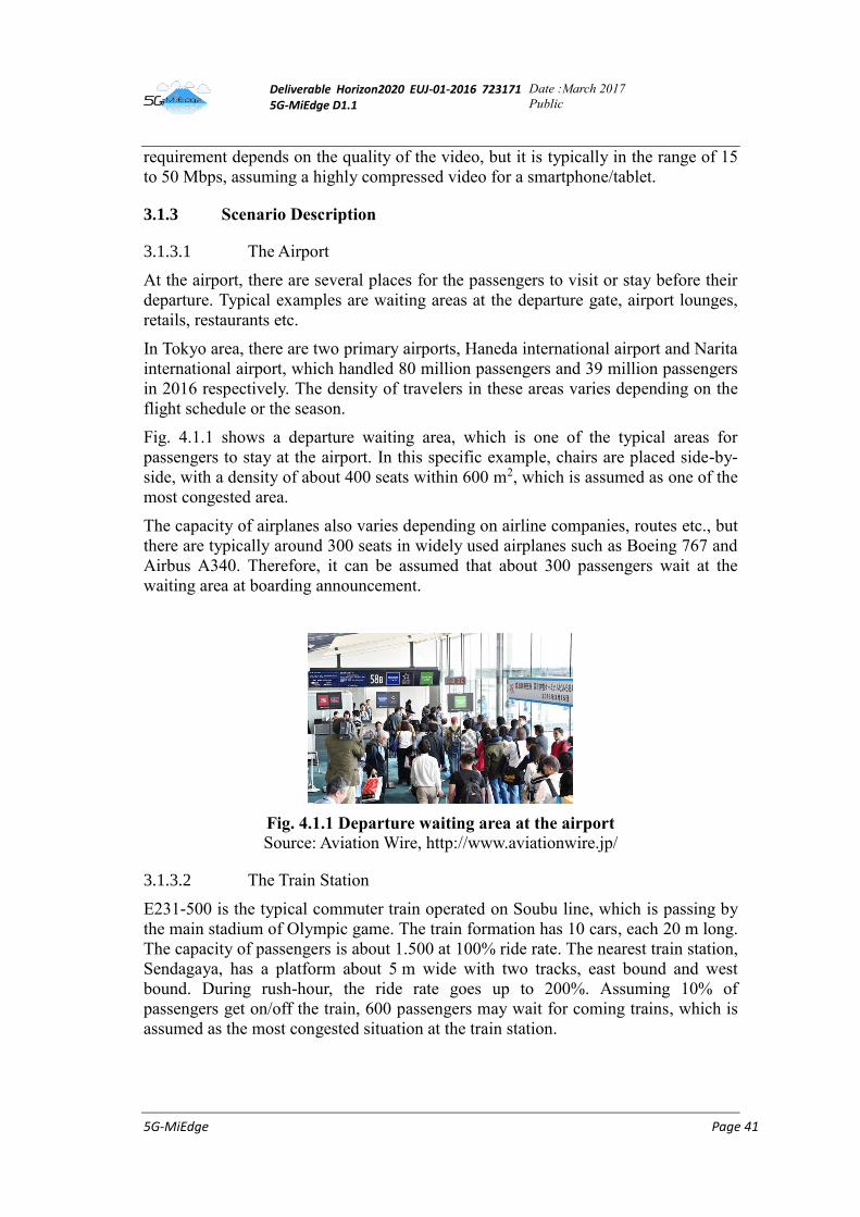
Deliverable Horizon2020 EUJ-01-2016 723171 5G-MiEdge D1.1
Date :March 2017
Public
5G-MiEdge Page 41
requirement depends on the quality of the video, but it is typically in the range of 15
to 50 Mbps, assuming a highly compressed video for a smartphone/tablet.
3.1.3 Scenario Description
3.1.3.1 The Airport
At the airport, there are several places for the passengers to visit or stay before their
departure. Typical examples are waiting areas at the departure gate, airport lounges,
retails, restaurants etc.
In Tokyo area, there are two primary airports, Haneda international airport and Narita
international airport, which handled 80 million passengers and 39 million passengers
in 2016 respectively. The density of travelers in these areas varies depending on the
flight schedule or the season.
Fig. 4.1.1 shows a departure waiting area, which is one of the typical areas for
passengers to stay at the airport. In this specific example, chairs are placed side-by-
side, with a density of about 400 seats within 600 m2, which is assumed as one of the
most congested area.
The capacity of airplanes also varies depending on airline companies, routes etc., but
there are typically around 300 seats in widely used airplanes such as Boeing 767 and
Airbus A340. Therefore, it can be assumed that about 300 passengers wait at the
waiting area at boarding announcement.
Fig. 4.1.1 Departure waiting area at the airport
Source: Aviation Wire, http://www.aviationwire.jp/
3.1.3.2 The Train Station
E231-500 is the typical commuter train operated on Soubu line, which is passing by
the main stadium of Olympic game. The train formation has 10 cars, each 20 m long.
The capacity of passengers is about 1.500 at 100% ride rate. The nearest train station,
Sendagaya, has a platform about 5 m wide with two tracks, east bound and west
bound. During rush-hour, the ride rate goes up to 200%. Assuming 10% of
passengers get on/off the train, 600 passengers may wait for coming trains, which is
assumed as the most congested situation at the train station.
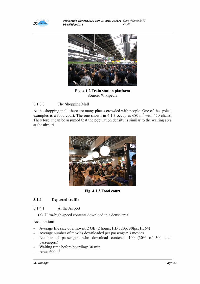
Deliverable Horizon2020 EUJ-01-2016 723171 5G-MiEdge D1.1
Date :March 2017
Public
5G-MiEdge Page 42
Fig. 4.1.2 Train station platform
Source: Wikipedia
3.1.3.3 The Shopping Mall
At the shopping mall, there are many places crowded with people. One of the typical
examples is a food court. The one shown in 4.1.3 occupies 680 m2 with 450 chairs.
Therefore, it can be assumed that the population density is similar to the waiting area
at the airport.
Fig. 4.1.3 Food court
3.1.4 Expected traffic
3.1.4.1 At the Airport
(a) Ultra-high-speed contents download in a dense area
Assumption:
- Average file size of a movie: 2 GB (2 hours, HD 720p, 30fps, H264)
- Average number of movies downloaded per passenger: 3 movies
- Number of passengers who download contents: 100 (30% of 300 total
passengers)
- Waiting time before boarding: 30 min.
- Area: 600m2
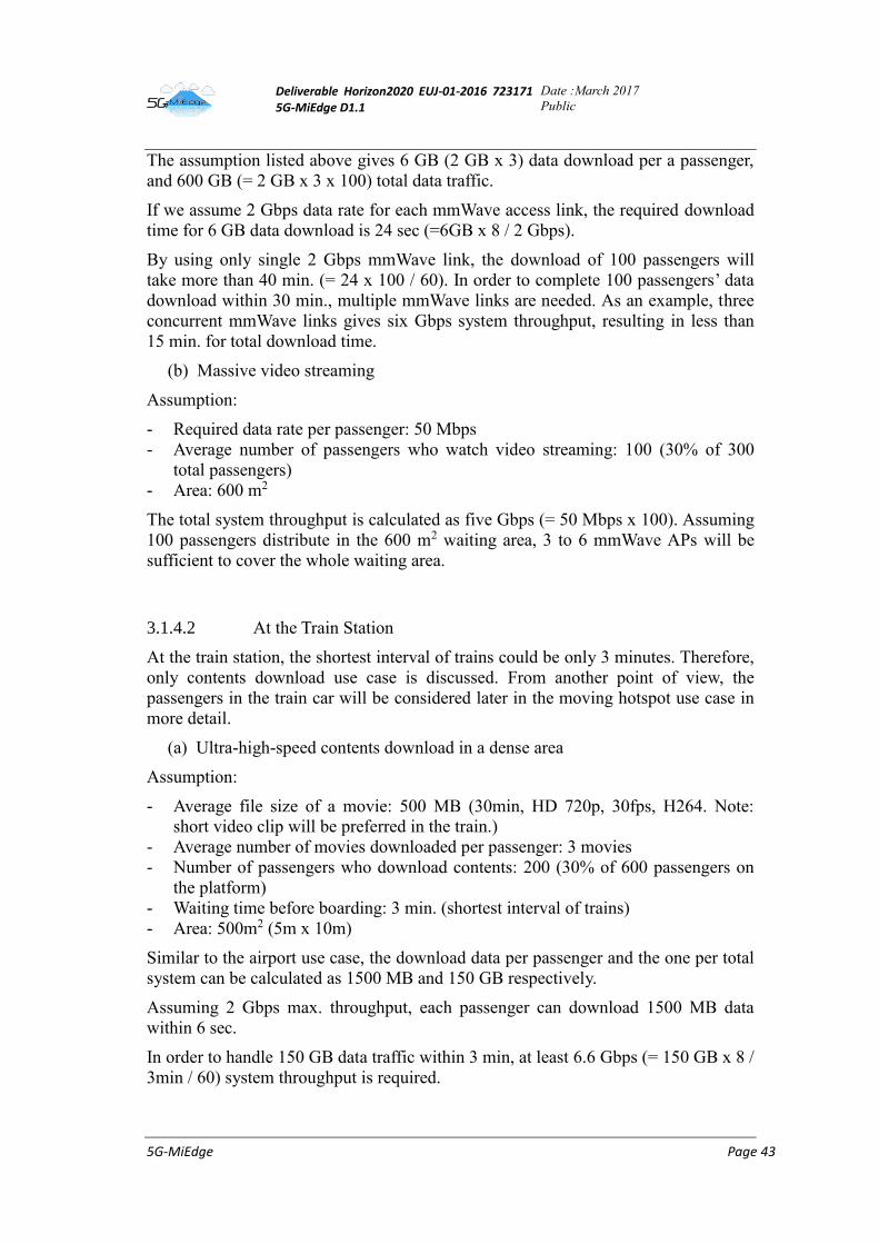
Deliverable Horizon2020 EUJ-01-2016 723171 5G-MiEdge D1.1
Date :March 2017
Public
5G-MiEdge Page 43
The assumption listed above gives 6 GB (2 GB x 3) data download per a passenger,
and 600 GB (= 2 GB x 3 x 100) total data traffic.
If we assume 2 Gbps data rate for each mmWave access link, the required download
time for 6 GB data download is 24 sec (=6GB x 8 / 2 Gbps).
By using only single 2 Gbps mmWave link, the download of 100 passengers will
take more than 40 min. (= 24 x 100 / 60). In order to complete 100 passengers’ data
download within 30 min., multiple mmWave links are needed. As an example, three
concurrent mmWave links gives six Gbps system throughput, resulting in less than
15 min. for total download time.
(b) Massive video streaming
Assumption:
- Required data rate per passenger: 50 Mbps
- Average number of passengers who watch video streaming: 100 (30% of 300
total passengers)
- Area: 600 m2
The total system throughput is calculated as five Gbps (= 50 Mbps x 100). Assuming
100 passengers distribute in the 600 m2 waiting area, 3 to 6 mmWave APs will be
sufficient to cover the whole waiting area.
3.1.4.2 At the Train Station
At the train station, the shortest interval of trains could be only 3 minutes. Therefore,
only contents download use case is discussed. From another point of view, the
passengers in the train car will be considered later in the moving hotspot use case in
more detail.
(a) Ultra-high-speed contents download in a dense area
Assumption:
- Average file size of a movie: 500 MB (30min, HD 720p, 30fps, H264. Note:
short video clip will be preferred in the train.)
- Average number of movies downloaded per passenger: 3 movies
- Number of passengers who download contents: 200 (30% of 600 passengers on
the platform)
- Waiting time before boarding: 3 min. (shortest interval of trains)
- Area: 500m2 (5m x 10m)
Similar to the airport use case, the download data per passenger and the one per total
system can be calculated as 1500 MB and 150 GB respectively.
Assuming 2 Gbps max. throughput, each passenger can download 1500 MB data
within 6 sec.
In order to handle 150 GB data traffic within 3 min, at least 6.6 Gbps (= 150 GB x 8 /
3min / 60) system throughput is required.
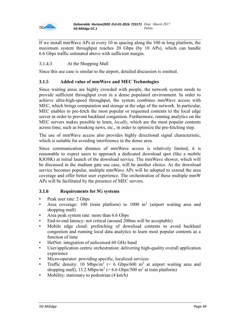
Deliverable Horizon2020 EUJ-01-2016 723171 5G-MiEdge D1.1
Date :March 2017
Public
5G-MiEdge Page 44
If we install mmWave APs at every 10 m spacing along the 100 m long platform, the
maximum system throughput reaches 20 Gbps (by 10 APs), which can handle
6.6 Gbps traffic estimated above with sufficient margin.
3.1.4.3 At the Shopping Mall
Since this use case is similar to the airport, detailed discussion is omitted.
3.1.5 Added value of mmWave and MEC Technologies
Since waiting areas are highly crowded with people, the network system needs to
provide sufficient throughput even in a dense populated environment. In order to
achieve ultra-high-speed throughput, the system combines mmWave access with
MEC, which brings computation and storage at the edge of the network. In particular,
MEC enables to pre-fetch the most popular or requested contents to the local edge
server in order to prevent backhaul congestion. Furthermore, running analytics on the
MEC servers makes possible to learn, locally, which are the most popular contents
across time, such as breaking news, etc., in order to optimize the pre-fetching step.
The use of mmWave access also provides highly directional signal characteristic,
which is suitable for avoiding interference in the dense area.
Since communication distance of mmWave access is relatively limited, it is
reasonable to expect users to approach a dedicated download spot (like a mobile
KIOSK) at initial launch of the download service. The mmWave shower, which will
be discussed in the stadium gate use case, will be another choice. As the download
service becomes popular, multiple mmWave APs will be adopted to extend the area
coverage and offer better user experience. The orchestration of these multiple mmW
APs will be facilitated by the presence of MEC servers.
3.1.6 Requirements for 5G systems
• Peak user rate: 2 Gbps
• Area coverage: 100 (train platform) to 1000 m2 (airport waiting area and
shopping mall)
• Area peak system rate: more than 6.6 Gbps
• End-to-end latency: not critical (around 200ms will be acceptable)
• Mobile edge cloud: prefetching of download contents to avoid backhaul
congestion and running local data analytics to learn most popular contents as a
function of time
• HetNet: integration of unlicensed 60 GHz band
• User/application centric orchestration: delivering high-quality overall application
experience
• Micro-operator: providing specific, localized services
• Traffic density: 10 Mbps/m2 (= 6 Gbps/600 m2 at airport waiting area and
shopping mall), 13.2 Mbps/m2 (= 6.6 Gbps/500 m2 at train platform)
• Mobility: stationary to pedestrian (4 km/h)
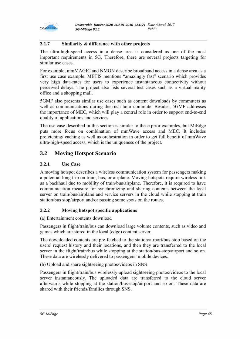
Deliverable Horizon2020 EUJ-01-2016 723171 5G-MiEdge D1.1
Date :March 2017
Public
5G-MiEdge Page 45
3.1.7 Similarity & difference with other projects
The ultra-high-speed access in a dense area is considered as one of the most
important requirements in 5G. Therefore, there are several projects targeting for
similar use cases.
For example, mmMAGIC and NMGN describe broadband access in a dense area as a
first use case example. METIS mentions “amazingly fast” scenario which provides
very high data-rates for users to experience instantaneous connectivity without
perceived delays. The project also lists several test cases such as a virtual reality
office and a shopping mall.
5GMF also presents similar use cases such as content downloads by commuters as
well as communications during the rush hour commute. Besides, 5GMF addresses
the importance of MEC, which will play a central role in order to support end-to-end
quality of applications and services.
The use case described in this section is similar to these prior examples, but MiEdge
puts more focus on combination of mmWave access and MEC. It includes
prefetching/ caching as well as orchestration in order to get full benefit of mmWave
ultra-high-speed access, which is the uniqueness of the project.
3.2 Moving Hotspot Scenario
3.2.1 Use Case
A moving hotspot describes a wireless communication system for passengers making
a potential long trip on train, bus, or airplane. Moving hotspots require wireless link
as a backhaul due to mobility of train/bus/airplane. Therefore, it is required to have
communication measure for synchronizing and sharing contents between the local
server on train/bus/airplane and service servers in the cloud while stopping at train
station/bus stop/airport and/or passing some spots on the routes.
3.2.2 Moving hotspot specific applications
(a) Entertainment contents download
Passengers in flight/train/bus can download large volume contents, such as video and
games which are stored in the local (edge) content server.
The downloaded contents are pre-fetched to the station/airport/bus-stop based on the
users’ request history and their locations, and then they are transferred to the local
server in the flight/train/bus while stopping at the station/bus-stop/airport and so on.
These data are wirelessly delivered to passengers’ mobile devices.
(b) Upload and share sightseeing photos/videos in SNS
Passengers in flight/train/bus wirelessly upload sightseeing photos/videos to the local
server instantaneously. The uploaded data are transferred to the cloud server
afterwards while stopping at the station/bus-stop/airport and so on. These data are
shared with their friends/families through SNS.
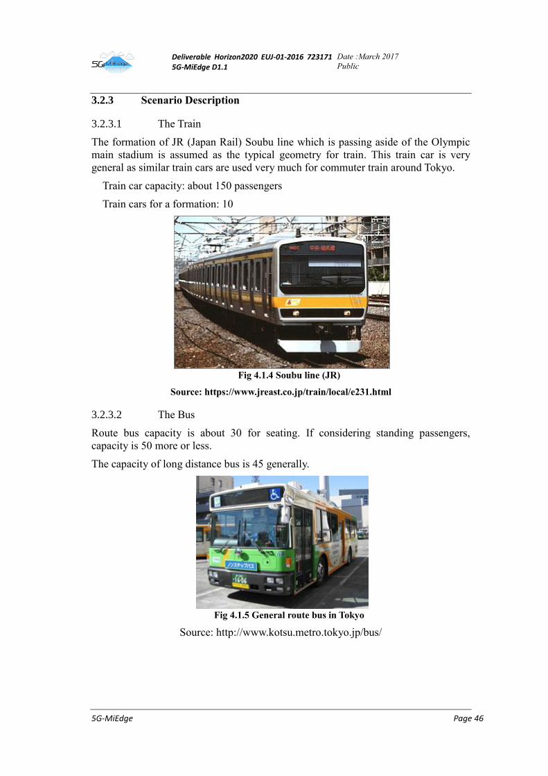
Deliverable Horizon2020 EUJ-01-2016 723171 5G-MiEdge D1.1
Date :March 2017
Public
5G-MiEdge Page 46
3.2.3 Scenario Description
3.2.3.1 The Train
The formation of JR (Japan Rail) Soubu line which is passing aside of the Olympic
main stadium is assumed as the typical geometry for train. This train car is very
general as similar train cars are used very much for commuter train around Tokyo.
Train car capacity: about 150 passengers
Train cars for a formation: 10
Fig 4.1.4 Soubu line (JR)
Source: https://www.jreast.co.jp/train/local/e231.html
3.2.3.2 The Bus
Route bus capacity is about 30 for seating. If considering standing passengers,
capacity is 50 more or less.
The capacity of long distance bus is 45 generally.
Fig 4.1.5 General route bus in Tokyo
Source: http://www.kotsu.metro.tokyo.jp/bus/
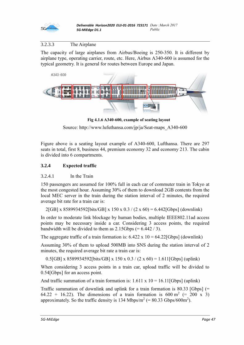
Deliverable Horizon2020 EUJ-01-2016 723171 5G-MiEdge D1.1
Date :March 2017
Public
5G-MiEdge Page 47
3.2.3.3 The Airplane
The capacity of large airplanes from Airbus/Boeing is 250-350. It is different by
airplane type, operating carrier, route, etc. Here, Airbus A340-600 is assumed for the
typical geometry. It is general for routes between Europe and Japan.
Fig 4.1.6 A340-600, example of seating layout
Source: http://www.lufuthansa.com/jp/ja/Seat-maps_A340-600
Figure above is a seating layout example of A340-600, Lufthansa. There are 297
seats in total, first 8, business 44, premium economy 32 and economy 213. The cabin
is divided into 6 compartments.
3.2.4 Expected traffic
3.2.4.1 In the Train
150 passengers are assumed for 100% full in each car of commuter train in Tokyo at
the most congested hour. Assuming 30% of them to download 2GB contents from the
local MEC server in the train during the station interval of 2 minutes, the required
average bit rate for a train car is:
2[GB] x 8589934592[bits/GB] x 150 x 0.3 / (2 x 60) = 6.442[Gbps] (downlink)
In order to moderate link blockage by human bodies, multiple IEEE802.11ad access
points may be necessary inside a car. Considering 3 access points, the required
bandwidth will be divided to them as 2.15Gbps (= 6.442 / 3).
The aggregate traffic of a train formation is: 6.422 x 10 = 64.22[Gbps] (downlink)
Assuming 30% of them to upload 500MB into SNS during the station interval of 2
minutes, the required average bit rate a train car is:
0.5[GB] x 8589934592[bits/GB] x 150 x 0.3 / (2 x 60) = 1.611[Gbps] (uplink)
When considering 3 access points in a train car, upload traffic will be divided to
0.54[Gbps] for an access point.
And traffic summation of a train formation is: 1.611 x 10 = 16.11[Gbps] (uplink)
Traffic summation of downlink and uplink for a train formation is 80.33 [Gbps] (=
64.22 + 16.22). The dimensions of a train formation is 600 m2 (= 200 x 3)
approximately. So the traffic density is 134 Mbps/m2 (= 80.33 Gbps/600m2).
Deliverable Horizon2020 EUJ-01-2016 723171 5G-MiEdge D1.1
Date :March 2017
Public
5G-MiEdge Page 48
Mobility is about 120 km/h for commuter train at the fastest. However, it is not
necessary to consider mobility between user’s devices and the local server.
Passengers are still inside a train car.
It is not so critical on latency between user’s devices and the local server. It is
acceptable to have 100 ms latency at the worst because of content characteristics of
this use case.
Regarding backhaul for synchronizing and sharing contents between the local MEC
server on train and cloud servers, it may be sufficient to have 10Gbps link for
transferring contents at stations. It can transfer data of 75GB (= 10G / 8 x 60)
approximately in a minute. However, it depends on interval between spots for
synchronization and algorithm of prefetching/caching. They will also affect the
storage size of the local MEC server.
3.2.4.2 In the Bus
50 passengers are assumed for a bus at the most. Applying the same traffic model as
the one for train, 1/3 traffic will be generated.
6.442 / 3 = 2.147 [Gbps] for downlink
1.611 / 3 = 0.537 [Gbps] for uplink
The traffic summation of downlink and uplink is 2.684[Gbps] (= 2.147 + 0.537). The
dimensions of a bus is 25 m2 (= 10 x 2.5) approximately. So the traffic density is
107Mbps/m2 (= 2.684 Gbps/25m2).
Mobility is about 50 km/h for bus at the fastest. However, it is not necessary to
consider mobility between user’s devices and the local server. Passengers are still
inside a bus.
It is not so critical on latency between user’s devices and the local server. It is
acceptable to have 100ms latency at the worst because of content characteristics of
this use case.
Regarding backhaul for synchronizing and sharing contents between the local MEC
server on train and cloud servers, it may be sufficient to have 1Gbps link for
transferring contents at stations. It can transfer data of 3.8 GB (= 1G / 8 x 30)
approximately in 30 seconds. Coming-in/going-out of passengers is less dynamic
than train. Frequency of content update to the local MEC server may be moderate.
However, it depends on interval between spots for synchronization and algorithm of
prefetching/caching. They will also affect the storage size of the local MEC server.
3.2.4.3 Inside the Airplane
It is around 30 minutes for mmWave access to be considered as the most congested
minutes just after permission of radio emission from personal devices in the cabin
after taking off.
Assuming one access point for a compartment, the densest compartment is economy
class. There are 213 passengers in two economy class compartments. Assuming
100% of them to download 2GB content in 30 minutes, the required average bit rate
in a compartment is:
Deliverable Horizon2020 EUJ-01-2016 723171 5G-MiEdge D1.1
Date :March 2017
Public
5G-MiEdge Page 49
2 [GB] x 8589934592 [bits/GB] x 213 / 2 x 1.0 / (30 x 60) = 1.016 [Gbps]
(downlink)
Traffic summation of the entire cabin: 1.016 x 297 / (213 / 2) = 2.833 [Gbps]
Assuming just 1 hour available for mmWave access during domestic flight,
passengers can upload their contents of sightseeing pictures or videos to SNS within
the time. Their upload will be random and disperse. In such situation, the required
average rate for the entire cabin is:
0.5 [GB] x 8589934592 [bits/GB] x 297 / (60 x 60) = 354.3 [Mbps]
The traffic summation of downlink and uplink is 3.187 [Gbps] (= 2.833 Gbps +
354 Mbps). The dimensions of an airplane is 323 m2 (= 61 x 5.3) approximately. So
the traffic density is 10 Mbps/m2 (= 3.187 Gbps/323m2).
Mobility is 1000 km/h for airplane at the fastest. However, it is not necessary to
consider mobility between user’s devices and the local server. Passengers are still
inside an airplane.
It is not so critical on latency between user’s devices and the local server. It is
acceptable to have 100 ms latency at the worst because of content characteristics of
this use case.
Regarding backhaul for airplanes, there is no chance to have sufficient bandwidth
during its flight except satellite link, except when flying over land with sufficient
ground bound communication infrastructure. Considering these characteristics,
download of local contents from the local MEC server is the main use case. Those
downloads will occur only during flight. Therefore, it is not necessary to consider
frequent updates of content on the local MEC server at airports. When considering
that all passengers upload contents to SNS during flight, data of 149 GB (= 0.5 GB x
297) will be generated. Considering 2 Gbps link for backhaul at airport, all uploaded
contents will be transferred in 10 minutes (= 149 x 8 / 2 / 60). It will be finished
during passengers disembarking.
3.2.5 Added value of mmWave and MEC Technologies
The mobile hotspot consists of Wi-Fi/WiGig access point, local MEC server, and
other components to deliver video content and games to passengers. Moreover,
passengers upload sightseeing photos/videos into SNS. Uploaded contents will be
stored in local MEC server temporarily and transferred to the cloud when backhaul
bandwidth is sufficient. When a user starts wireless communication via mmWave
inside the vehicle, its traffic flow will be transferred to the local MEC/content server.
He can select/download favorite large volume contents like videos or games based on
suggestions provided by portal page on the local MEC server. General web browsing
and SNS communications could be realized by the local MEC server behaving as a
proxy content server. The users can enjoy contents without being conscious of the
difference from regular Internet communication. At this time, it is important that
MEC properly caches or pre-fetches content according to user/application demands.
Deliverable Horizon2020 EUJ-01-2016 723171 5G-MiEdge D1.1
Date :March 2017
Public
5G-MiEdge Page 50
Adding computation capabilities in the MEC servers in terms of capability to
instantiate and run vurtual machines, makes possible to learn the content popularity,
across space and time, to optimize the cache pre-fetching step. Regarding upload,
distributed server functions on the local MEC server will temporarily cache uploaded
contents by users such as photos/videos. The users can upload their contents also
without being conscious of the difference from regular SNS uploading. The uploaded
contents temporarily cached on the local MEC server will be transferred to the cloud
when the vehicle obtains sufficient bandwidth of backhaul at stations/bus
stops/airports and so on.
3.2.6 Requirements for 5G systems
3.2.6.1 Train
• High peak data rate for user link: DL: 2.15 Gbps, UL: 0.54 Gbps
• High peak data rate (e.g. 10Gbps) for backhaul at stations for synchronizing with
cloud servers
• mmWave (WiGig) access inside train cars for high data rate with counter-
measures for link blockage by passengers
• Area coverage: 10 – 20m
• MEC server(s) in a train formation for data prefetching/caching
• Distributed server function of SNS on the local MEC server
• Traffic density: 134 Mbps/m2 (80.33 Gbps/600m2)
• Mobility: 120 km/h, but passengers are still inside a train car
3.2.6.2 Bus
• High peak data rate for user link: DL:2.147 Gbps, UL:0.537 Gbps
• High peak data rate (e.g. 1 Gbps) for backhaul at bus stops for synchronizing
with cloud servers
• mmWave (WiGig) access inside buses for high data rate with counter-measures
for link blockage by passengers
• Area coverage: 10m
• MEC server in a bus for data prefetching/caching
• Distributed server function of SNS on the local MEC server
• Traffic density: 134 Mbps/m2 (2.684 Gbps/25m2)
• Mobility: 50 km/h, but passengers are still inside a bus
3.2.6.3 Airplane
• High peak data rate for user link: DL:2.833 Gbps, UL:354.2 Mbps
• High peak data rate (e.g. 2 Gbps) for backhaul at airports for synchronizing with
cloud servers
• mmWave (WiGig) access inside airplane for high data rate with counter-
measures for link blockage by seat backs and passengers
• Area coverage: 10m for a compartment of the cabin
• MEC server in an airplane for data prefetching/caching
• Distributed server function of SNS on the local MEC server
• Traffic density: 10 Mbps/m2 (3.187 Gbps/323m2)
• Mobility: 1000 km/h, but passengers are still inside an airplane
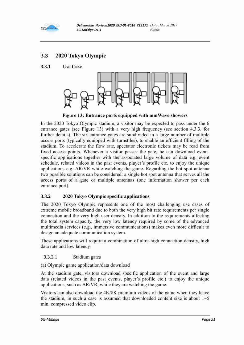
Deliverable Horizon2020 EUJ-01-2016 723171 5G-MiEdge D1.1
Date :March 2017
Public
5G-MiEdge Page 51
3.3 2020 Tokyo Olympic
3.3.1 Use Case
Figure 13: Entrance ports equipped with mmWave showers
In the 2020 Tokyo Olympic stadium, a visitor may be expected to pass under the 6
entrance gates (see Figure 13) with a very high frequency (see section 4.3.3. for
further details). The six entrance gates are subdivided in a large number of multiple
access ports (typically equipped with turnstiles), to enable an efficient filling of the
stadium. To accelerate the flow rate, spectator electronic tickets may be read from
fixed access points. Whenever a visitor passes the gate, he can download event-
specific applications together with the associated large volume of data e.g. event
schedule, related videos in the past events, player’s profile etc. to enjoy the unique
applications e.g. AR/VR while watching the game. Regarding the hot spot antenna
two possible solutions can be considered: a single hot spot antenna that serves all the
access ports of a gate or multiple antennas (one information shower per each
entrance port).
3.3.2 2020 Tokyo Olympic specific applications
The 2020 Tokyo Olympic represents one of the most challenging use cases of
extreme mobile broadband due to both the very high bit rate requirements per single
connection and the very high user density. In addition to the requirements affecting
the total system capacity, the very low latency required by some of the advanced
multimedia services (e.g., immersive communications) makes even more difficult to
design an adequate communication system.
These applications will require a combination of ultra-high connection density, high
data rate and low latency.
3.3.2.1 Stadium gates
(a) Olympic game application/data download
At the stadium gate, visitors download specific application of the event and large
data (related videos in the past events, player’s profile etc.) to enjoy the unique
applications, such as AR/VR, while they are watching the game.
Visitors can also download the 4K/8K premium videos of the game when they leave
the stadium, in such a case is assumed that downloaded content size is about 1~5
min. compressed video clip.
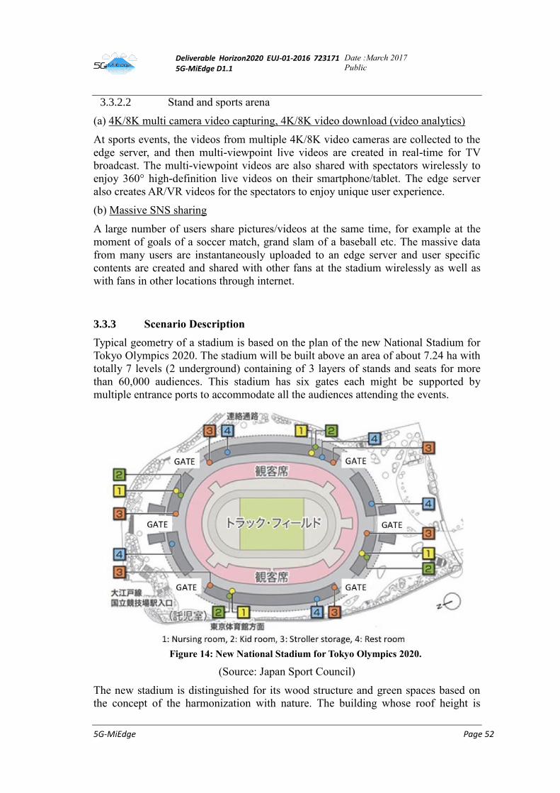
Deliverable Horizon2020 EUJ-01-2016 723171 5G-MiEdge D1.1
Date :March 2017
Public
5G-MiEdge Page 52
3.3.2.2 Stand and sports arena
(a) 4K/8K multi camera video capturing, 4K/8K video download (video analytics)
At sports events, the videos from multiple 4K/8K video cameras are collected to the
edge server, and then multi-viewpoint live videos are created in real-time for TV
broadcast. The multi-viewpoint videos are also shared with spectators wirelessly to
enjoy 360° high-definition live videos on their smartphone/tablet. The edge server
also creates AR/VR videos for the spectators to enjoy unique user experience.
(b) Massive SNS sharing
A large number of users share pictures/videos at the same time, for example at the
moment of goals of a soccer match, grand slam of a baseball etc. The massive data
from many users are instantaneously uploaded to an edge server and user specific
contents are created and shared with other fans at the stadium wirelessly as well as
with fans in other locations through internet.
3.3.3 Scenario Description
Typical geometry of a stadium is based on the plan of the new National Stadium for
Tokyo Olympics 2020. The stadium will be built above an area of about 7.24 ha with
totally 7 levels (2 underground) containing of 3 layers of stands and seats for more
than 60,000 audiences. This stadium has six gates each might be supported by
multiple entrance ports to accommodate all the audiences attending the events.
Figure 14: New National Stadium for Tokyo Olympics 2020.
(Source: Japan Sport Council)
The new stadium is distinguished for its wood structure and green spaces based on
the concept of the harmonization with nature. The building whose roof height is
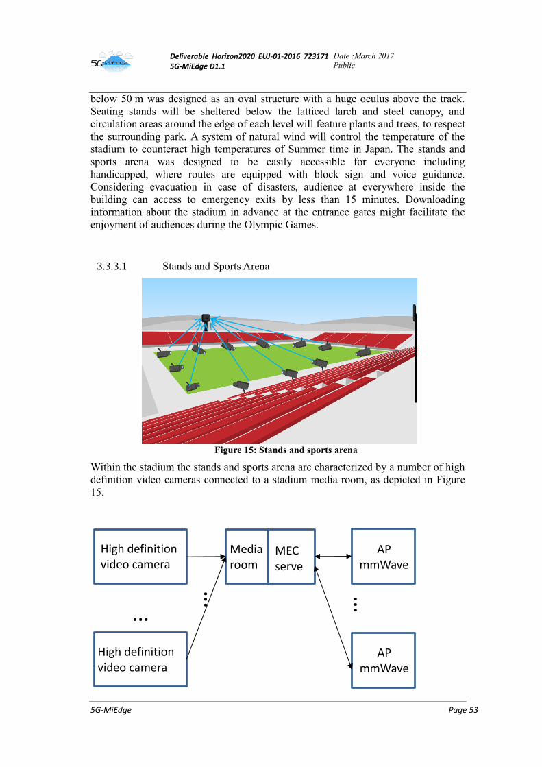
Deliverable Horizon2020 EUJ-01-2016 723171 5G-MiEdge D1.1
Date :March 2017
Public
5G-MiEdge Page 53
below 50 m was designed as an oval structure with a huge oculus above the track.
Seating stands will be sheltered below the latticed larch and steel canopy, and
circulation areas around the edge of each level will feature plants and trees, to respect
the surrounding park. A system of natural wind will control the temperature of the
stadium to counteract high temperatures of Summer time in Japan. The stands and
sports arena was designed to be easily accessible for everyone including
handicapped, where routes are equipped with block sign and voice guidance.
Considering evacuation in case of disasters, audience at everywhere inside the
building can access to emergency exits by less than 15 minutes. Downloading
information about the stadium in advance at the entrance gates might facilitate the
enjoyment of audiences during the Olympic Games.
3.3.3.1 Stands and Sports Arena
Figure 15: Stands and sports arena
Within the stadium the stands and sports arena are characterized by a number of high
definition video cameras connected to a stadium media room, as depicted in Figure
15.
High definition
video camera
High definition
video camera
…
Media
room
…
MEC
server
AP
mmWave
…
AP
mmWave
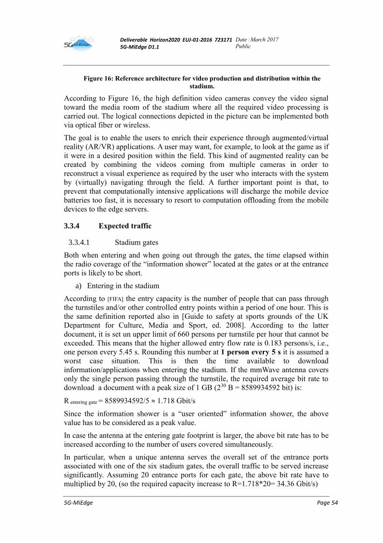
Deliverable Horizon2020 EUJ-01-2016 723171 5G-MiEdge D1.1
Date :March 2017
Public
5G-MiEdge Page 54
Figure 16: Reference architecture for video production and distribution within the
stadium.
According to Figure 16, the high definition video cameras convey the video signal
toward the media room of the stadium where all the required video processing is
carried out. The logical connections depicted in the picture can be implemented both
via optical fiber or wireless.
The goal is to enable the users to enrich their experience through augmented/virtual
reality (AR/VR) applications. A user may want, for example, to look at the game as if
it were in a desired position within the field. This kind of augmented reality can be
created by combining the videos coming from multiple cameras in order to
reconstruct a visual experience as required by the user who interacts with the system
by (virtually) navigating through the field. A further important point is that, to
prevent that computationally intensive applications will discharge the mobile device
batteries too fast, it is necessary to resort to computation offloading from the mobile
devices to the edge servers.
3.3.4 Expected traffic
3.3.4.1 Stadium gates
Both when entering and when going out through the gates, the time elapsed within
the radio coverage of the “information shower” located at the gates or at the entrance
ports is likely to be short.
a) Entering in the stadium
According to [FIFA] the entry capacity is the number of people that can pass through
the turnstiles and/or other controlled entry points within a period of one hour. This is
the same definition reported also in [Guide to safety at sports grounds of the UK
Department for Culture, Media and Sport, ed. 2008]. According to the latter
document, it is set un upper limit of 660 persons per turnstile per hour that cannot be
exceeded. This means that the higher allowed entry flow rate is 0.183 persons/s, i.e.,
one person every 5.45 s. Rounding this number at 1 person every 5 s it is assumed a
worst case situation. This is then the time available to download
information/applications when entering the stadium. If the mmWave antenna covers
only the single person passing through the turnstile, the required average bit rate to
download a document with a peak size of 1 GB (230 B = 8589934592 bit) is:
R entering gate = 8589934592/5 ≈ 1.718 Gbit/s
Since the information shower is a “user oriented” information shower, the above
value has to be considered as a peak value.
In case the antenna at the entering gate footprint is larger, the above bit rate has to be
increased according to the number of users covered simultaneously.
In particular, when a unique antenna serves the overall set of the entrance ports
associated with one of the six stadium gates, the overall traffic to be served increase
significantly. Assuming 20 entrance ports for each gate, the above bit rate have to
multiplied by 20, (so the required capacity increase to R=1.718*20= 34.36 Gbit/s)
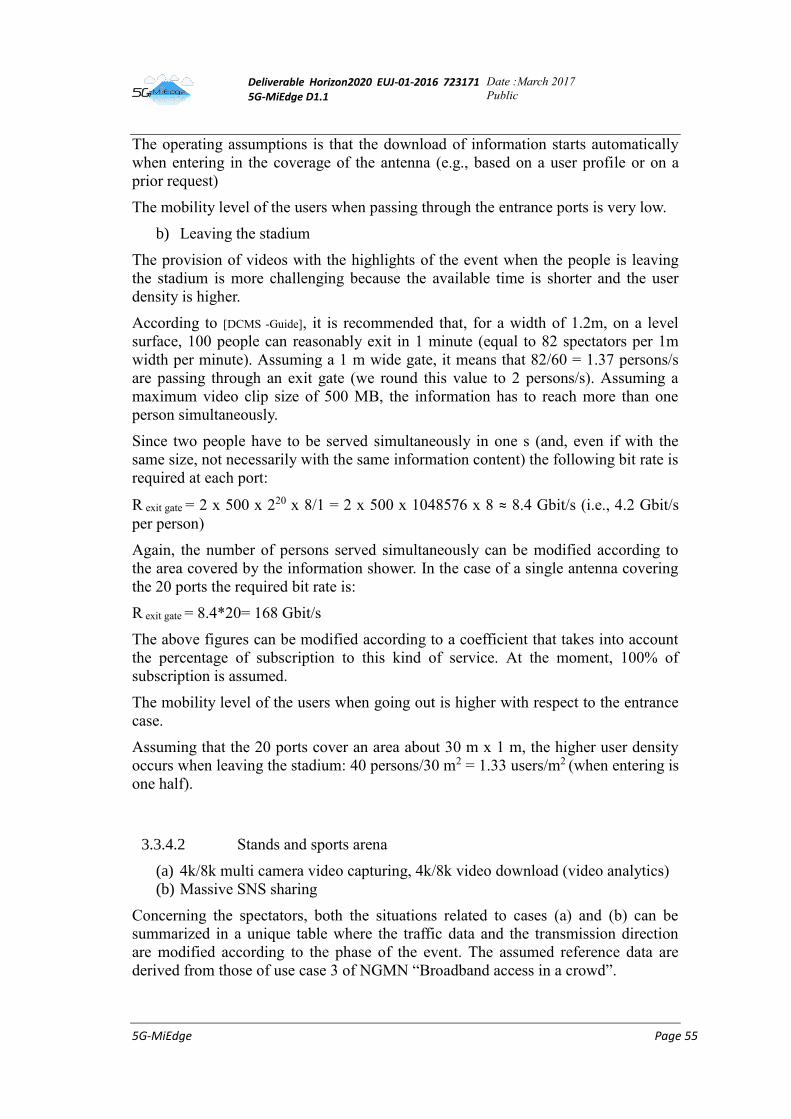
Deliverable Horizon2020 EUJ-01-2016 723171 5G-MiEdge D1.1
Date :March 2017
Public
5G-MiEdge Page 55
The operating assumptions is that the download of information starts automatically
when entering in the coverage of the antenna (e.g., based on a user profile or on a
prior request)
The mobility level of the users when passing through the entrance ports is very low.
b) Leaving the stadium
The provision of videos with the highlights of the event when the people is leaving
the stadium is more challenging because the available time is shorter and the user
density is higher.
According to [DCMS -Guide], it is recommended that, for a width of 1.2m, on a level
surface, 100 people can reasonably exit in 1 minute (equal to 82 spectators per 1m
width per minute). Assuming a 1 m wide gate, it means that 82/60 = 1.37 persons/s
are passing through an exit gate (we round this value to 2 persons/s). Assuming a
maximum video clip size of 500 MB, the information has to reach more than one
person simultaneously.
Since two people have to be served simultaneously in one s (and, even if with the
same size, not necessarily with the same information content) the following bit rate is
required at each port:
R exit gate = 2 x 500 x 220 x 8/1 = 2 x 500 x 1048576 x 8 ≈ 8.4 Gbit/s (i.e., 4.2 Gbit/s
per person)
Again, the number of persons served simultaneously can be modified according to
the area covered by the information shower. In the case of a single antenna covering
the 20 ports the required bit rate is:
R exit gate = 8.4*20= 168 Gbit/s
The above figures can be modified according to a coefficient that takes into account
the percentage of subscription to this kind of service. At the moment, 100% of
subscription is assumed.
The mobility level of the users when going out is higher with respect to the entrance
case.
Assuming that the 20 ports cover an area about 30 m x 1 m, the higher user density
occurs when leaving the stadium: 40 persons/30 m2 = 1.33 users/m2 (when entering is
one half).
3.3.4.2 Stands and sports arena
(a) 4k/8k multi camera video capturing, 4k/8k video download (video analytics)
(b) Massive SNS sharing
Concerning the spectators, both the situations related to cases (a) and (b) can be
summarized in a unique table where the traffic data and the transmission direction
are modified according to the phase of the event. The assumed reference data are
derived from those of use case 3 of NGMN “Broadband access in a crowd”.
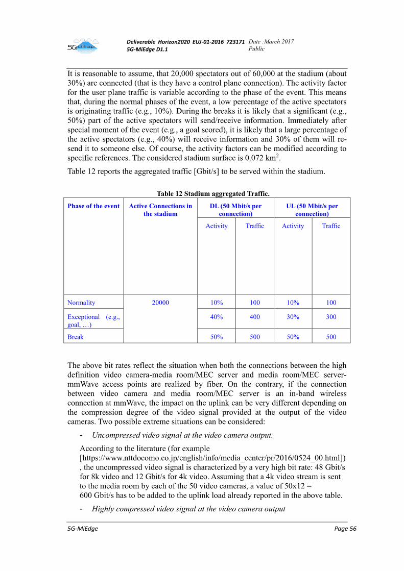
Deliverable Horizon2020 EUJ-01-2016 723171 5G-MiEdge D1.1
Date :March 2017
Public
5G-MiEdge Page 56
It is reasonable to assume, that 20,000 spectators out of 60,000 at the stadium (about
30%) are connected (that is they have a control plane connection). The activity factor
for the user plane traffic is variable according to the phase of the event. This means
that, during the normal phases of the event, a low percentage of the active spectators
is originating traffic (e.g., 10%). During the breaks it is likely that a significant (e.g.,
50%) part of the active spectators will send/receive information. Immediately after
special moment of the event (e.g., a goal scored), it is likely that a large percentage of
the active spectators (e.g., 40%) will receive information and 30% of them will re-
send it to someone else. Of course, the activity factors can be modified according to
specific references. The considered stadium surface is 0.072 km2.
Table 12 reports the aggregated traffic [Gbit/s] to be served within the stadium.
Table 12 Stadium aggregated Traffic.
Phase of the event Active Connections in
the stadium
DL (50 Mbit/s per
connection)
UL (50 Mbit/s per
connection)
Activity
f
a
c
t
o
r
Traffic
[
G
b
i
t
/
s
]
Activity
f
a
c
t
o
r
Traffic
[
G
b
i
t
/
s
]
Normality 20000 10% 100 10% 100
Exceptional (e.g.,
goal, …)
40% 400 30% 300
Break 50% 500 50% 500
The above bit rates reflect the situation when both the connections between the high
definition video camera-media room/MEC server and media room/MEC server-
mmWave access points are realized by fiber. On the contrary, if the connection
between video camera and media room/MEC server is an in-band wireless
connection at mmWave, the impact on the uplink can be very different depending on
the compression degree of the video signal provided at the output of the video
cameras. Two possible extreme situations can be considered:
- Uncompressed video signal at the video camera output.
According to the literature (for example
[https://www.nttdocomo.co.jp/english/info/media_center/pr/2016/0524_00.html])
, the uncompressed video signal is characterized by a very high bit rate: 48 Gbit/s
for 8k video and 12 Gbit/s for 4k video. Assuming that a 4k video stream is sent
to the media room by each of the 50 video cameras, a value of 50x12 =
600 Gbit/s has to be added to the uplink load already reported in the above table.
- Highly compressed video signal at the video camera output
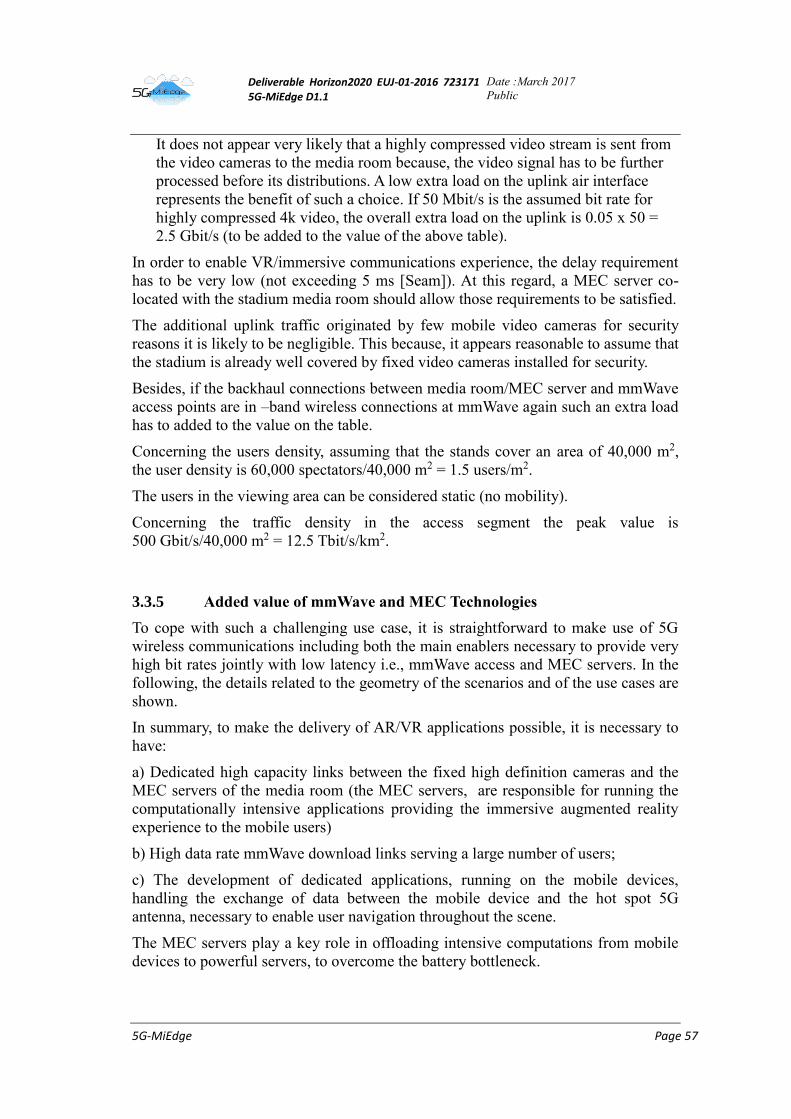
Deliverable Horizon2020 EUJ-01-2016 723171 5G-MiEdge D1.1
Date :March 2017
Public
5G-MiEdge Page 57
It does not appear very likely that a highly compressed video stream is sent from
the video cameras to the media room because, the video signal has to be further
processed before its distributions. A low extra load on the uplink air interface
represents the benefit of such a choice. If 50 Mbit/s is the assumed bit rate for
highly compressed 4k video, the overall extra load on the uplink is 0.05 x 50 =
2.5 Gbit/s (to be added to the value of the above table).
In order to enable VR/immersive communications experience, the delay requirement
has to be very low (not exceeding 5 ms [Seam]). At this regard, a MEC server co-
located with the stadium media room should allow those requirements to be satisfied.
The additional uplink traffic originated by few mobile video cameras for security
reasons it is likely to be negligible. This because, it appears reasonable to assume that
the stadium is already well covered by fixed video cameras installed for security.
Besides, if the backhaul connections between media room/MEC server and mmWave
access points are in –band wireless connections at mmWave again such an extra load
has to added to the value on the table.
Concerning the users density, assuming that the stands cover an area of 40,000 m2,
the user density is 60,000 spectators/40,000 m2 = 1.5 users/m2.
The users in the viewing area can be considered static (no mobility).
Concerning the traffic density in the access segment the peak value is
500 Gbit/s/40,000 m2 = 12.5 Tbit/s/km2.
3.3.5 Added value of mmWave and MEC Technologies
To cope with such a challenging use case, it is straightforward to make use of 5G
wireless communications including both the main enablers necessary to provide very
high bit rates jointly with low latency i.e., mmWave access and MEC servers. In the
following, the details related to the geometry of the scenarios and of the use cases are
shown.
In summary, to make the delivery of AR/VR applications possible, it is necessary to
have:
a) Dedicated high capacity links between the fixed high definition cameras and the
MEC servers of the media room (the MEC servers, are responsible for running the
computationally intensive applications providing the immersive augmented reality
experience to the mobile users)
b) High data rate mmWave download links serving a large number of users;
c) The development of dedicated applications, running on the mobile devices,
handling the exchange of data between the mobile device and the hot spot 5G
antenna, necessary to enable user navigation throughout the scene.
The MEC servers play a key role in offloading intensive computations from mobile
devices to powerful servers, to overcome the battery bottleneck.
Deliverable Horizon2020 EUJ-01-2016 723171 5G-MiEdge D1.1
Date :March 2017
Public
5G-MiEdge Page 58
3.3.6 Requirements for 5G systems
• User rate: Minimum rate 50 Mbit/s (value arising from the assumptions we have
done for the users on the stands)
• Area coverage (range): The minimum cell range is the one required by the
information shower at each turnstile (i.e., 0.5 m radius).
• Area (system) rate: Total of 500 Gbit/s to serve the stands area of the stadium,
radio access segment
• End-to-end latency: 5ms (for immersive reality)
• Requirements on backhaul: 1.718 Gbit/s + required overhead (single information
shower per turnstile when entering)
• Requirements on computation: For applications using MEC functionality
3.3.7 Similarity & difference with other projects
The stadium scenario has been considered by several projects/international bodies as
one of the most challenging for significant 5G use cases as those previously
described (e.g., extreme mobile broadband for video content
download/sharing/streaming and virtual/immersive reality). The challenge is mainly
represented by the very high traffic density to be served. This scenario has been
taken into account by projects like mmMAGIC, METIS-I/II and by international fora
like 5GMF, NGMN, 3GPP.
The use cases/scenarios provided by those projects/fora, show a high-level general
alignment with respect to what came out within 5G-MiEdge. Some differences can
be noticed in the traffic density that, in 5G-MiEdge is higher (this because 5G-
MiEdge assumes that many spectators ask for services based on very high definition
video contents). The assumed minimum latency appears aligned with METIS-I/II.
The international fora 5GMF is the one describing the usage scenario most aligned
with the 5G-MiEdge/Olympic Game Stadium when talking about
Entertainment/Enhanced real experience entertainment (shared experiences and
virtual reality experience). It has to be highlighted that in 5G-MiEdge Olympic game
stadium the very challenging requirements are not uniformly spread over the overall
stadium area but are concentrated at the gates/entrance ports areas and on the stands
inside the arena. Moreover, the MEC related considerations concerning running
context aware data analytics and implementing effective caching strategies are a
characterizing element of this project.
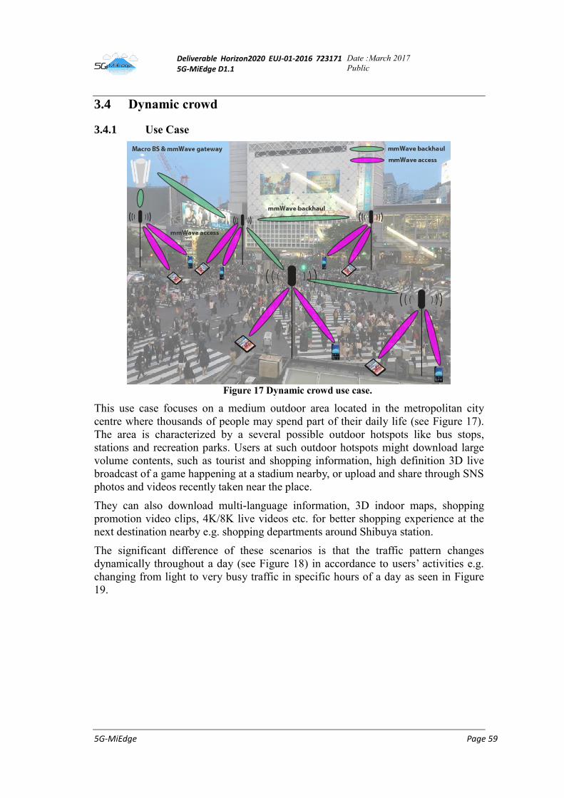
Deliverable Horizon2020 EUJ-01-2016 723171 5G-MiEdge D1.1
Date :March 2017
Public
5G-MiEdge Page 59
3.4 Dynamic crowd
3.4.1 Use Case
Figure 17 Dynamic crowd use case.
This use case focuses on a medium outdoor area located in the metropolitan city
centre where thousands of people may spend part of their daily life (see Figure 17).
The area is characterized by a several possible outdoor hotspots like bus stops,
stations and recreation parks. Users at such outdoor hotspots might download large
volume contents, such as tourist and shopping information, high definition 3D live
broadcast of a game happening at a stadium nearby, or upload and share through SNS
photos and videos recently taken near the place.
They can also download multi-language information, 3D indoor maps, shopping
promotion video clips, 4K/8K live videos etc. for better shopping experience at the
next destination nearby e.g. shopping departments around Shibuya station.
The significant difference of these scenarios is that the traffic pattern changes
dynamically throughout a day (see Figure 18) in accordance to users’ activities e.g.
changing from light to very busy traffic in specific hours of a day as seen in Figure
19.
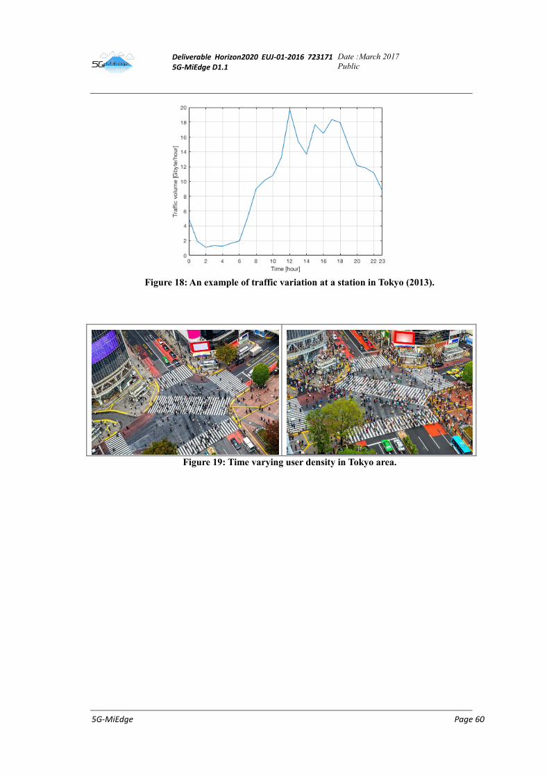
Deliverable Horizon2020 EUJ-01-2016 723171 5G-MiEdge D1.1
Date :March 2017
Public
5G-MiEdge Page 60
Figure 18: An example of traffic variation at a station in Tokyo (2013).
Figure 19: Time varying user density in Tokyo area.
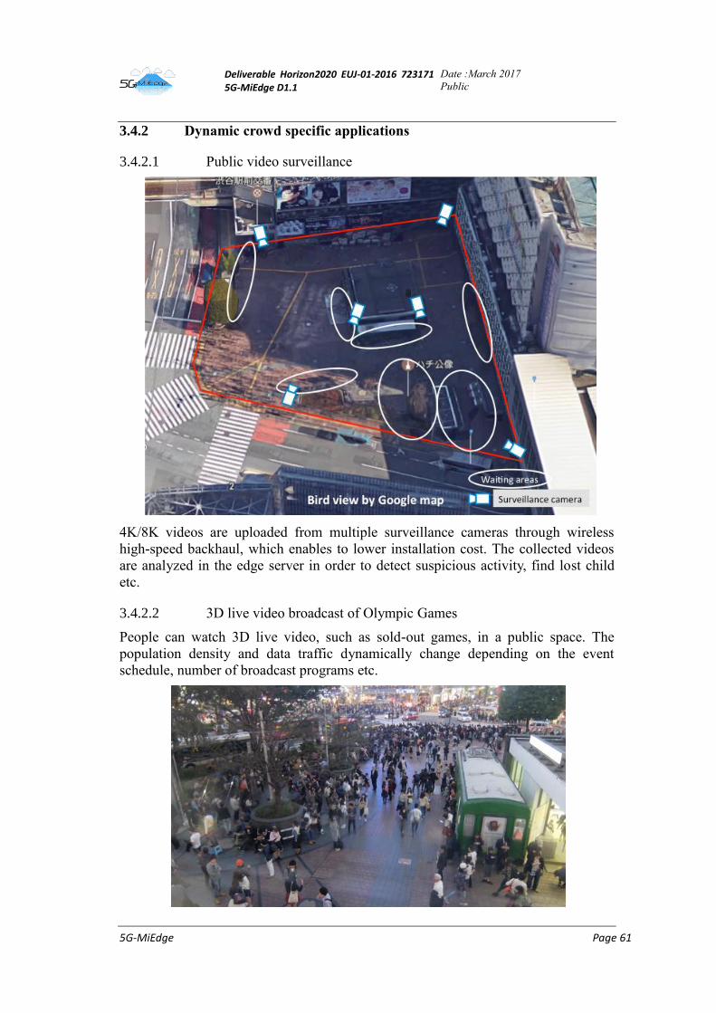
Deliverable Horizon2020 EUJ-01-2016 723171 5G-MiEdge D1.1
Date :March 2017
Public
5G-MiEdge Page 61
3.4.2 Dynamic crowd specific applications
3.4.2.1 Public video surveillance
4K/8K videos are uploaded from multiple surveillance cameras through wireless
high-speed backhaul, which enables to lower installation cost. The collected videos
are analyzed in the edge server in order to detect suspicious activity, find lost child
etc.
3.4.2.2 3D live video broadcast of Olympic Games
People can watch 3D live video, such as sold-out games, in a public space. The
population density and data traffic dynamically change depending on the event
schedule, number of broadcast programs etc.
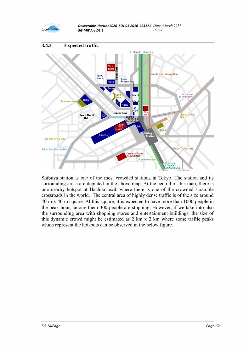
Deliverable Horizon2020 EUJ-01-2016 723171 5G-MiEdge D1.1
Date :March 2017
Public
5G-MiEdge Page 62
3.4.3 Expected traffic
Shibuya station is one of the most crowded stations in Tokyo. The station and its
surrounding areas are depicted in the above map. At the central of this map, there is
one nearby hotspot at Hachiko exit, where there is one of the crowded scramble
crossroads in the world. The central area of highly dense traffic is of the size around
40 m x 40 m square. At this square, it is expected to have more than 1000 people in
the peak hour, among them 300 people are stopping. However, if we take into also
the surrounding area with shopping stores and entertainment buildings, the size of
this dynamic crowd might be estimated as 2 km x 2 km where some traffic peaks
which represent the hotspots can be observed in the below figure.
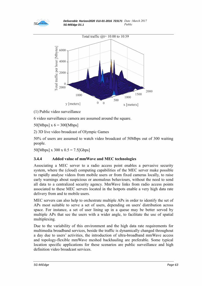
Deliverable Horizon2020 EUJ-01-2016 723171 5G-MiEdge D1.1
Date :March 2017
Public
5G-MiEdge Page 63
(1) Public video surveillance
6 video surveillance camera are assumed around the square.
50[Mbps] x 6 = 300[Mbps]
2) 3D live video broadcast of Olympic Games
50% of users are assumed to watch video broadcast of 50Mbps out of 300 waiting
people.
50[Mbps] x 300 x 0.5 = 7.5[Gbps]
3.4.4 Added value of mmWave and MEC technologies
Associating a MEC server to a radio access point enables a pervasive security
system, where the (cloud) computing capabilities of the MEC server make possible
to rapidly analyse videos from mobile users or from fixed cameras locally, to raise
early warnings about suspicious or anomalous behaviours, without the need to send
all data to a centralized security agency. MmWave links from radio access points
associated to these MEC servers located in the hotpots enable a very high data rate
delivery from and to mobile users.
MEC servers can also help to orchestrate multiple APs in order to identify the set of
APs most suitable to serve a set of users, depending on users' distribution across
space. For instance, a set of user lining up in a queue may be better served by
multiple APs that see the users with a wider angle, to facilitate the use of spatial
multiplexing.
Due to the variability of this environment and the high data rate requirements for
multimedia broadband services, beside the traffic is dynamically changed throughout
a day due to users’ activities, the introduction of ultra-broadband mmWave access
and topology-flexible mmWave meshed backhauling are preferable. Some typical
location specific applications for these scenarios are public surveillance and high
definition video broadcast services.
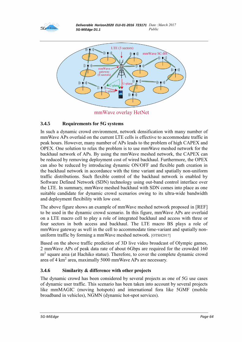
Deliverable Horizon2020 EUJ-01-2016 723171 5G-MiEdge D1.1
Date :March 2017
Public
5G-MiEdge Page 64
3.4.5 Requirements for 5G systems
In such a dynamic crowd environment, network densification with many number of
mmWave APs overlaid on the current LTE cells is effective to accommodate traffic in
peak hours. However, many number of APs leads to the problem of high CAPEX and
OPEX. One solution to relax the problem is to use mmWave meshed network for the
backhaul network of APs. By using the mmWave meshed network, the CAPEX can
be reduced by removing deployment cost of wired backhaul. Furthermore, the OPEX
can also be reduced by introducing dynamic ON/OFF and flexible path creation in
the backhaul network in accordance with the time variant and spatially non-uniform
traffic distributions. Such flexible control of the backhaul network is enabled by
Software Defined Network (SDN) technology using out-band control interface over
the LTE. In summary, mmWave meshed backhaul with SDN comes into place as one
suitable candidate for dynamic crowd scenarios owing to its ultra-wide bandwidth
and deployment flexibility with low cost.
The above figure shows an example of mmWave meshed network proposed in [REF]
to be used in the dynamic crowd scenario. In this figure, mmWave APs are overlaid
on a LTE macro cell to play a role of integrated backhaul and access with three or
four sectors in both access and backhaul. The LTE macro BS plays a role of
mmWave gateway as well in the cell to accommodate time-variant and spatially non-
uniform traffic by forming a mmWave meshed network. [OTSH2017]
Based on the above traffic prediction of 3D live video broadcast of Olympic games,
2 mmWave APs of peak data rate of about 6Gbps are required for the crowded 160
m2 square area (at Hachiko statue). Therefore, to cover the complete dynamic crowd
area of 4 km2 area, maximally 5000 mmWave APs are necessary.
3.4.6 Similarity & difference with other projects
The dynamic crowd has been considered by several projects as one of 5G use cases
of dynamic user traffic. This scenario has been taken into account by several projects
like mmMAGIC (moving hotspots) and international fora like 5GMF (mobile
broadband in vehicles), NGMN (dynamic hot-spot services).
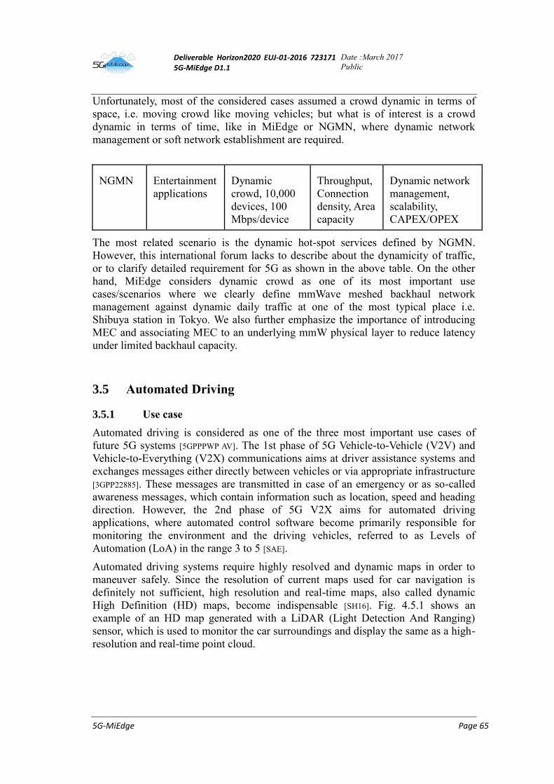
Deliverable Horizon2020 EUJ-01-2016 723171 5G-MiEdge D1.1
Date :March 2017
Public
5G-MiEdge Page 65
Unfortunately, most of the considered cases assumed a crowd dynamic in terms of
space, i.e. moving crowd like moving vehicles; but what is of interest is a crowd
dynamic in terms of time, like in MiEdge or NGMN, where dynamic network
management or soft network establishment are required.
NGMN Entertainment
applications
Dynamic
crowd, 10,000
devices, 100
Mbps/device
Throughput,
Connection
density, Area
capacity
Dynamic network
management,
scalability,
CAPEX/OPEX
The most related scenario is the dynamic hot-spot services defined by NGMN.
However, this international forum lacks to describe about the dynamicity of traffic,
or to clarify detailed requirement for 5G as shown in the above table. On the other
hand, MiEdge considers dynamic crowd as one of its most important use
cases/scenarios where we clearly define mmWave meshed backhaul network
management against dynamic daily traffic at one of the most typical place i.e.
Shibuya station in Tokyo. We also further emphasize the importance of introducing
MEC and associating MEC to an underlying mmW physical layer to reduce latency
under limited backhaul capacity.
3.5 Automated Driving
3.5.1 Use case
Automated driving is considered as one of the three most important use cases of
future 5G systems [5GPPPWP AV]. The 1st phase of 5G Vehicle-to-Vehicle (V2V) and
Vehicle-to-Everything (V2X) communications aims at driver assistance systems and
exchanges messages either directly between vehicles or via appropriate infrastructure
[3GPP22885]. These messages are transmitted in case of an emergency or as so-called
awareness messages, which contain information such as location, speed and heading
direction. However, the 2nd phase of 5G V2X aims for automated driving
applications, where automated control software become primarily responsible for
monitoring the environment and the driving vehicles, referred to as Levels of
Automation (LoA) in the range 3 to 5 [SAE].
Automated driving systems require highly resolved and dynamic maps in order to
maneuver safely. Since the resolution of current maps used for car navigation is
definitely not sufficient, high resolution and real-time maps, also called dynamic
High Definition (HD) maps, become indispensable [SH16]. Fig. 4.5.1 shows an
example of an HD map generated with a LiDAR (Light Detection And Ranging)
sensor, which is used to monitor the car surroundings and display the same as a high-
resolution and real-time point cloud.
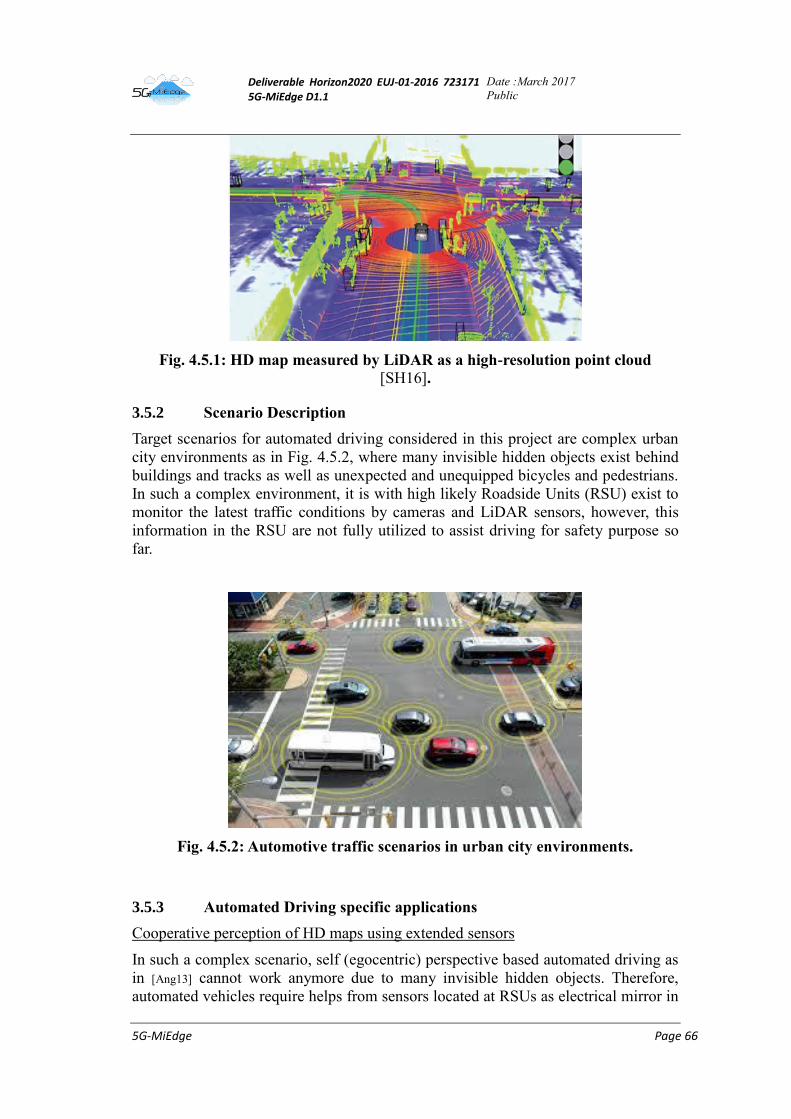
Deliverable Horizon2020 EUJ-01-2016 723171 5G-MiEdge D1.1
Date :March 2017
Public
5G-MiEdge Page 66
Fig. 4.5.1: HD map measured by LiDAR as a high-resolution point cloud
[SH16].
3.5.2 Scenario Description
Target scenarios for automated driving considered in this project are complex urban
city environments as in Fig. 4.5.2, where many invisible hidden objects exist behind
buildings and tracks as well as unexpected and unequipped bicycles and pedestrians.
In such a complex environment, it is with high likely Roadside Units (RSU) exist to
monitor the latest traffic conditions by cameras and LiDAR sensors, however, this
information in the RSU are not fully utilized to assist driving for safety purpose so
far.
Fig. 4.5.2: Automotive traffic scenarios in urban city environments.
3.5.3 Automated Driving specific applications
Cooperative perception of HD maps using extended sensors
In such a complex scenario, self (egocentric) perspective based automated driving as
in [Ang13] cannot work anymore due to many invisible hidden objects. Therefore,
automated vehicles require helps from sensors located at RSUs as electrical mirror in
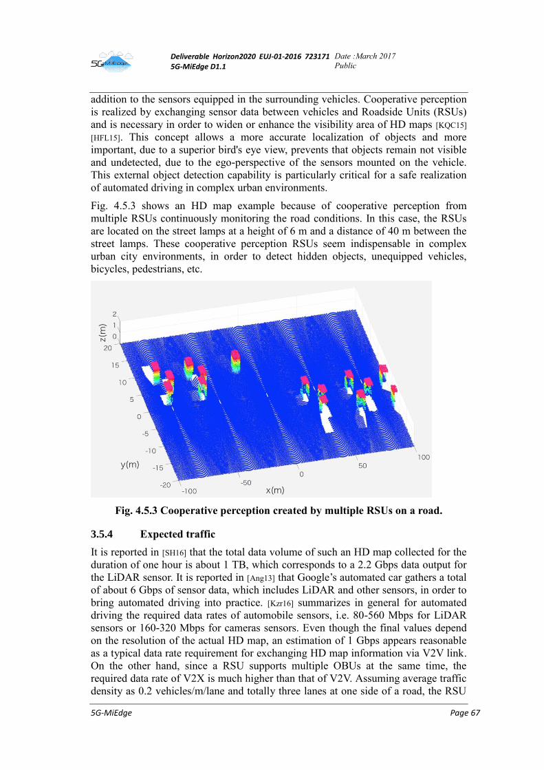
Deliverable Horizon2020 EUJ-01-2016 723171 5G-MiEdge D1.1
Date :March 2017
Public
5G-MiEdge Page 67
addition to the sensors equipped in the surrounding vehicles. Cooperative perception
is realized by exchanging sensor data between vehicles and Roadside Units (RSUs)
and is necessary in order to widen or enhance the visibility area of HD maps [KQC15]
[HFL15]. This concept allows a more accurate localization of objects and more
important, due to a superior bird's eye view, prevents that objects remain not visible
and undetected, due to the ego-perspective of the sensors mounted on the vehicle.
This external object detection capability is particularly critical for a safe realization
of automated driving in complex urban environments.
Fig. 4.5.3 shows an HD map example because of cooperative perception from
multiple RSUs continuously monitoring the road conditions. In this case, the RSUs
are located on the street lamps at a height of 6 m and a distance of 40 m between the
street lamps. These cooperative perception RSUs seem indispensable in complex
urban city environments, in order to detect hidden objects, unequipped vehicles,
bicycles, pedestrians, etc.
Fig. 4.5.3 Cooperative perception created by multiple RSUs on a road.
3.5.4 Expected traffic
It is reported in [SH16] that the total data volume of such an HD map collected for the
duration of one hour is about 1 TB, which corresponds to a 2.2 Gbps data output for
the LiDAR sensor. It is reported in [Ang13] that Google’s automated car gathers a total
of about 6 Gbps of sensor data, which includes LiDAR and other sensors, in order to
bring automated driving into practice. [Kzr16] summarizes in general for automated
driving the required data rates of automobile sensors, i.e. 80-560 Mbps for LiDAR
sensors or 160-320 Mbps for cameras sensors. Even though the final values depend
on the resolution of the actual HD map, an estimation of 1 Gbps appears reasonable
as a typical data rate requirement for exchanging HD map information via V2V link.
On the other hand, since a RSU supports multiple OBUs at the same time, the
required data rate of V2X is much higher than that of V2V. Assuming average traffic
density as 0.2 vehicles/m/lane and totally three lanes at one side of a road, the RSU
Deliverable Horizon2020 EUJ-01-2016 723171 5G-MiEdge D1.1
Date :March 2017
Public
5G-MiEdge Page 68
located every 40 m should support average 24 Gbps data rate. This data rate can be
relaxed by introducing multicast transmission within a group of vehicles close to
each other. If eight vehicles in the same lane are grouped, the required data rate
becomes 4 Gbps/group.
The communication range supported by a cooperative perception system can be
determined by the braking distance of vehicles. As an example, [GB01][Tra07] estimate
100 meters as a braking distance (including a safety increment distance) for the
emergency stop of a generic sedan car at 70 km/h, which can be seen as the
maximum speed in urban city environments. This braking distance estimate could be
raised to 150 meters for buses or trucks. Hence, the HD map exchange system should
support a communication range of at least 150 meters for emergency braking
applications. This number is to some extent comparable to the numbers given by
[Gic15].
At the end, latency is the most crucial communication system parameter in order to
realize a stable control. It’s well known that latency and data rate are a tradeoff for
the case of video or LiDAR data transmission. The latest video data compression
technique reduces the data rate to one-tenth of the raw data rate. However, these
video compressions inevitably lead to higher latencies than the 10 ms required for
automated driving [5GPPPWP AV]. Furthermore, raw (or nearly raw) data is also needed
for liability reasons in case of an accident [KQC15].
3.5.5 Added value of mmWave and MEC Technologies
Based on the discussion in Sect. 3.5.4, the enhanced V2V/V2X communication
targeting at automated driving requires a data rate of 1Gbps per link, end-to-end
latency of less than 10 ms per link and a communication range of more than 150 m,
in order to put safe automated driving into practice by exchanging raw (or lightly
processed) sensor data. Such high requirements cannot be realized with current
technologies [3GPP22885]. Hence, 3GPP initiated related work in Release 15 and
beyond, which is named eV2X (enhanced V2X) [3GPP22886]. As a consequence,
the utilization of mmWave and MEC technologies are becoming increasingly
important for the field of automated driving.
Figure 4.5.4 shows an example of a system architecture for mmWave based
V2V/V2X in order to realize a real-time exchange of HD maps between On-Board
Units (OBUs) mounted in vehicles and RSUs. All communication links between
OBUs and RSUs are directly connected through proximity-based services, namely
Device-to-Device (D2D) communication, as specified in [3GPP23303]. However,
differently from standard D2D, this V2V/V2X system uses mmWave channels to
fulfill the requirements of 1 Gbps data rate and less than 10 ms latency. The
communication range of mmWave links can be extended to more than 150 m, if
highly directional antenna beams are used. One challenge in this system might be the
antenna beam alignment between OBUs and RSUs, however [VSB16] [CVG16]
show the feasibility of using mmWave in vehicular scenarios. The system coexists
with the conventional V2X system [3GPP22885], which supports cloud-based services
such as traffic jam forecast and long-range traffic navigation.
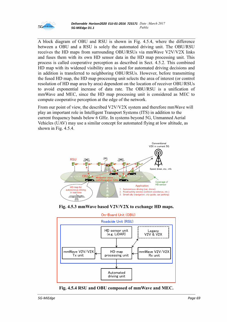
Deliverable Horizon2020 EUJ-01-2016 723171 5G-MiEdge D1.1
Date :March 2017
Public
5G-MiEdge Page 69
A block diagram of OBU and RSU is shown in Fig. 4.5.4, where the difference
between a OBU and a RSU is solely the automated driving unit. The OBU/RSU
receives the HD maps from surrounding OBU/RSUs via mmWave V2V/V2X links
and fuses them with its own HD sensor data in the HD map processing unit. This
process is called cooperative perception as described in Sect. 4.5.2. This combined
HD map with its widened visibility area is used for automated driving decisions and
in addition is transferred to neighboring OBU/RSUs. However, before transmitting
the fused HD map, the HD map processing unit selects the area of interest (or control
resolution of HD map area by area) dependent on the location of receiver OBU/RSUs
to avoid exponential increase of data rate. The OBU/RSU is a unification of
mmWave and MEC, since the HD map processing unit is considered as MEC to
compute cooperative perception at the edge of the network.
From our point of view, the described V2V/V2X system and therefore mmWave will
play an important role in Intelligent Transport Systems (ITS) in addition to the
current frequency bands below 6 GHz. In systems beyond 5G, Unmanned Aerial
Vehicles (UAV) may use a similar concept for automated flying at low altitude, as
shown in Fig. 4.5.4.
Fig. 4.5.3 mmWave based V2V/V2X to exchange HD maps.
Fig. 4.5.4 RSU and OBU composed of mmWave and MEC.
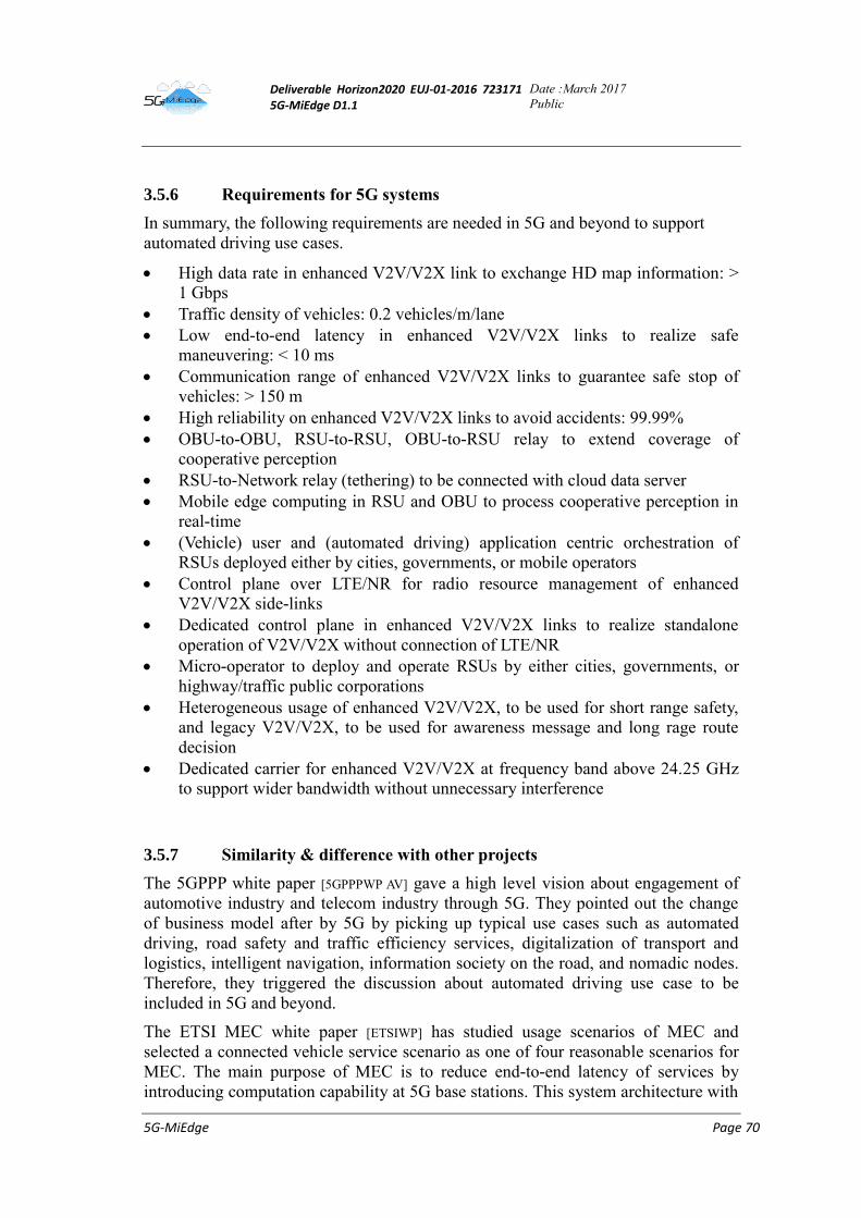
Deliverable Horizon2020 EUJ-01-2016 723171 5G-MiEdge D1.1
Date :March 2017
Public
5G-MiEdge Page 70
3.5.6 Requirements for 5G systems
In summary, the following requirements are needed in 5G and beyond to support
automated driving use cases.
High data rate in enhanced V2V/V2X link to exchange HD map information: >
1 Gbps
Traffic density of vehicles: 0.2 vehicles/m/lane
Low end-to-end latency in enhanced V2V/V2X links to realize safe
maneuvering: < 10 ms
Communication range of enhanced V2V/V2X links to guarantee safe stop of
vehicles: > 150 m
High reliability on enhanced V2V/V2X links to avoid accidents: 99.99%
OBU-to-OBU, RSU-to-RSU, OBU-to-RSU relay to extend coverage of
cooperative perception
RSU-to-Network relay (tethering) to be connected with cloud data server
Mobile edge computing in RSU and OBU to process cooperative perception in
real-time
(Vehicle) user and (automated driving) application centric orchestration of
RSUs deployed either by cities, governments, or mobile operators
Control plane over LTE/NR for radio resource management of enhanced
V2V/V2X side-links
Dedicated control plane in enhanced V2V/V2X links to realize standalone
operation of V2V/V2X without connection of LTE/NR
Micro-operator to deploy and operate RSUs by either cities, governments, or
highway/traffic public corporations
Heterogeneous usage of enhanced V2V/V2X, to be used for short range safety,
and legacy V2V/V2X, to be used for awareness message and long rage route
decision
Dedicated carrier for enhanced V2V/V2X at frequency band above 24.25 GHz
to support wider bandwidth without unnecessary interference
3.5.7 Similarity & difference with other projects
The 5GPPP white paper [5GPPPWP AV] gave a high level vision about engagement of
automotive industry and telecom industry through 5G. They pointed out the change
of business model after by 5G by picking up typical use cases such as automated
driving, road safety and traffic efficiency services, digitalization of transport and
logistics, intelligent navigation, information society on the road, and nomadic nodes.
Therefore, they triggered the discussion about automated driving use case to be
included in 5G and beyond.
The ETSI MEC white paper [ETSIWP] has studied usage scenarios of MEC and
selected a connected vehicle service scenario as one of four reasonable scenarios for
MEC. The main purpose of MEC is to reduce end-to-end latency of services by
introducing computation capability at 5G base stations. This system architecture with
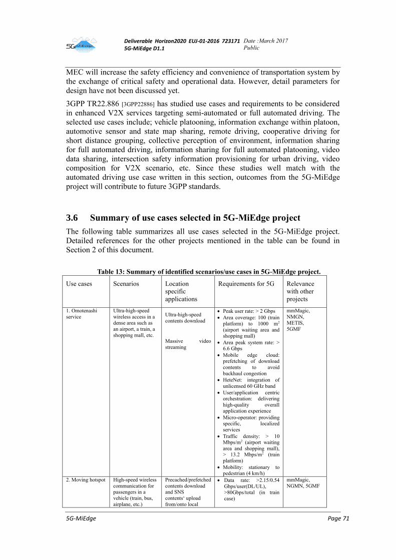
Deliverable Horizon2020 EUJ-01-2016 723171 5G-MiEdge D1.1
Date :March 2017
Public
5G-MiEdge Page 71
MEC will increase the safety efficiency and convenience of transportation system by
the exchange of critical safety and operational data. However, detail parameters for
design have not been discussed yet.
3GPP TR22.886 [3GPP22886] has studied use cases and requirements to be considered
in enhanced V2X services targeting semi-automated or full automated driving. The
selected use cases include; vehicle platooning, information exchange within platoon,
automotive sensor and state map sharing, remote driving, cooperative driving for
short distance grouping, collective perception of environment, information sharing
for full automated driving, information sharing for full automated platooning, video
data sharing, intersection safety information provisioning for urban driving, video
composition for V2X scenario, etc. Since these studies well match with the
automated driving use case written in this section, outcomes from the 5G-MiEdge
project will contribute to future 3GPP standards.
3.6 Summary of use cases selected in 5G-MiEdge project
The following table summarizes all use cases selected in the 5G-MiEdge project.
Detailed references for the other projects mentioned in the table can be found in
Section 2 of this document.
Table 13: Summary of identified scenarios/use cases in 5G-MiEdge project.
Use cases Scenarios Location
specific
applications
Requirements for 5G Relevance
with other
projects
1. Omotenashi
service
Ultra-high-speed
wireless access in a dense area such as
an airport, a train, a
shopping mall, etc.
Ultra-high-speed
contents download
Massive video
streaming
Peak user rate: > 2 Gbps
Area coverage: 100 (train
platform) to 1000 m2
(airport waiting area and shopping mall)
Area peak system rate: > 6.6 Gbps
Mobile edge cloud: prefetching of download
contents to avoid
backhaul congestion
HeteNet: integration of
unlicensed 60 GHz band
User/application centric orchestration: delivering
high-quality overall application experience
Micro-operator: providing specific, localized
services
Traffic density: > 10 Mbps/m2 (airport waiting
area and shopping mall), > 13.2 Mbps/m2 (train
platform)
Mobility: stationary to pedestrian (4 km/h)
mmMagic,
NMGN, METIS,
5GMF
2. Moving hotspot High-speed wireless
communication for passengers in a
vehicle (train, bus,
airplane, etc.)
Precached/prefetched
contents download and SNS
contents‘ upload
from/onto local
Data rate: >2.15/0.54
Gbps/user(DL/UL), >80Gbps/total (in train
case)
mmMagic,
NGMN, 5GMF
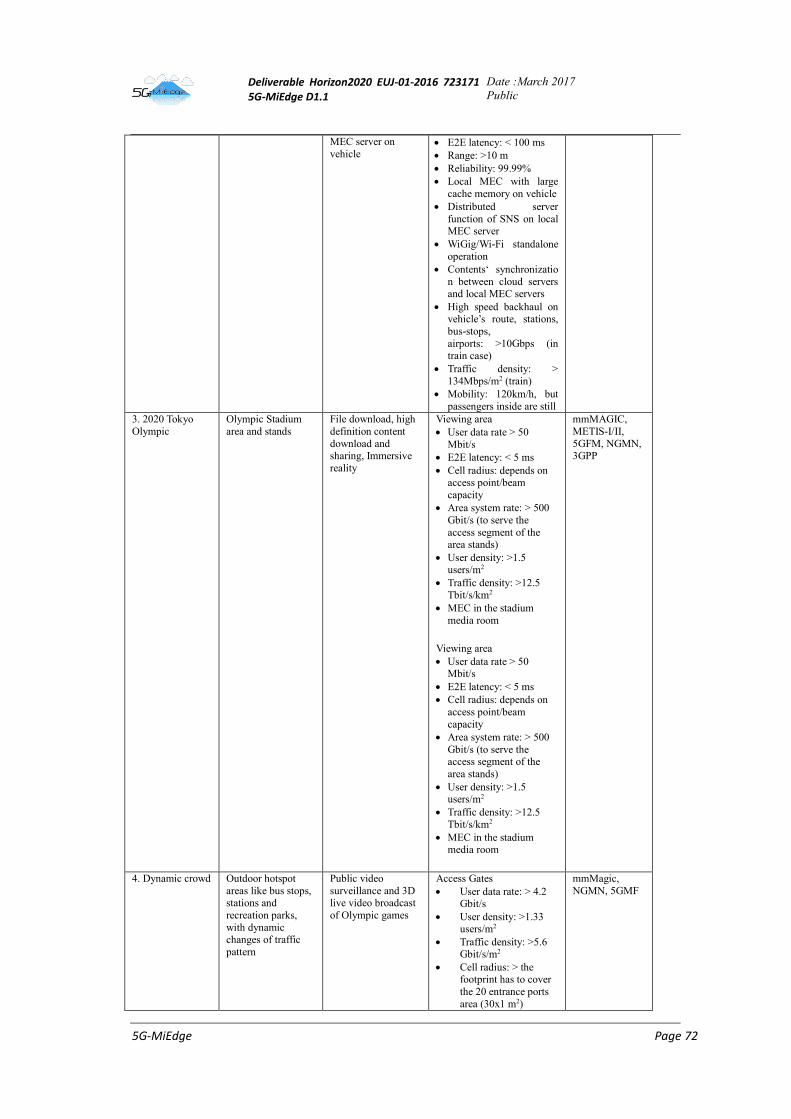
Deliverable Horizon2020 EUJ-01-2016 723171 5G-MiEdge D1.1
Date :March 2017
Public
5G-MiEdge Page 72
MEC server on
vehicle E2E latency: < 100 ms
Range: >10 m
Reliability: 99.99%
Local MEC with large
cache memory on vehicle
Distributed server
function of SNS on local MEC server
WiGig/Wi-Fi standalone
operation
Contents‘ synchronizatio
n between cloud servers and local MEC servers
High speed backhaul on vehicle’s route, stations,
bus-stops,
airports: >10Gbps (in
train case)
Traffic density: >
134Mbps/m2 (train)
Mobility: 120km/h, but
passengers inside are still
3. 2020 Tokyo
Olympic
Olympic Stadium
area and stands
File download, high
definition content
download and sharing, Immersive
reality
Viewing area
User data rate > 50
Mbit/s
E2E latency: < 5 ms
Cell radius: depends on access point/beam
capacity
Area system rate: > 500
Gbit/s (to serve the
access segment of the area stands)
User density: >1.5 users/m2
Traffic density: >12.5
Tbit/s/km2
MEC in the stadium
media room
Viewing area
User data rate > 50 Mbit/s
E2E latency: < 5 ms
Cell radius: depends on
access point/beam
capacity
Area system rate: > 500
Gbit/s (to serve the access segment of the
area stands)
User density: >1.5 users/m2
Traffic density: >12.5
Tbit/s/km2
MEC in the stadium media room
mmMAGIC,
METIS-I/II,
5GFM, NGMN, 3GPP
4. Dynamic crowd Outdoor hotspot
areas like bus stops, stations and
recreation parks,
with dynamic changes of traffic
pattern
Public video
surveillance and 3D live video broadcast
of Olympic games
Access Gates
User data rate: > 4.2 Gbit/s
User density: >1.33 users/m2
Traffic density: >5.6 Gbit/s/m2
Cell radius: > the footprint has to cover
the 20 entrance ports
area (30x1 m2)
mmMagic,
NGMN, 5GMF
Deliverable Horizon2020 EUJ-01-2016 723171 5G-MiEdge D1.1
Date :March 2017
Public
5G-MiEdge Page 73
Backhaul: > 168 Gbit/s (backhaul requested by a
cell covering 20 entrance
ports)
5. Automated driving
Automotive traffic environments in
urban city
Cooperative perception by
exchanging HD
dynamic map information between
vehicles & roadside units
Data rate: > 1 Gbps / link
Traffic density: 0.2 vehicles/m/lane
E2E latency: < 10 ms
Range: >150 m
Reliability: 99.99%
UE-UE, UE-network
relay
MEC in roadside units & on-board units
User/application centric orchestration
RRM via LTE/NR
Standalone operation
without LTE/NR
Micro-operator to be
deployed by government
Combination with legacy
V2V/V2X
Dedicated carrier above
24.25 GHz
5GPPP, ETSI MEC,
3GPP TR22.886
4 References
[3GPP] 3GPP website. Available online at: www.3gpp.org.
[3GPP22885] 3GPP TR22.885, “Study on LTE support for vehicle to everything (V2X) services,”
V14.0.0, Dec. 2015.
[3GPP22886] 3GPP TR22.886, “Study on enhancement of 3GPP support for 5G V2X services,”
V15.0.0, Dec. 2016.
[5GChamp] M. Mueck et al., "5G CHAMPION - Rolling out 5G in 2018," 2016 IEEE Globecom Workshops (GC Wkshps), Washington, DC, 2016, pp. 1-6.
[5GMFWP] 5GMF White Paper, “5G Mobile Communications systems for 2020 and beyond,” July
2016.
[5GPPPWP AV] 5GPPP White Paper, “5G automotive vision,” Oct. 2015
[5G-PPPWP] 5G-PPP, “5G-PPP use cases and performance evaluation modeling” v1.0, April 2016. Available: https://5g-ppp.eu/white-papers/
[Ang13] A. D. Angelica, “Google’s self-driving car gathers nearly 1GB/sec,” May 2014.
Available online: http://www.kurzweilai.net/googles-self-driving-car-gathers-nearly-1-
gbsec
[ATN16] M. Ando, T. Taniguchi, M. Noda, A. Yamaguchi, K. Sakaguchi, G.K. Tran, “PoC of
mmWave (40 and 60 GHz) Integrated 5G Heterogeneous Networks,” in Proc. EW2016,
May 2016.
[CHARISMA D6.1] The CHARISMA Deliverable D6.1 « Project presentation« . Available online at :
http://www.charisma5g.eu/index.php/deliverables.
[CHARISMA] The CHARISMA project website. Available online at : www.charisma5g.eu.
[DCMS -Guide] DCMS, "Guide to safety at Sports Grounds”, fifth edition, Available:
http://www.safetyatsportsgrounds.org.uk/sites/default/files/publications/green-guide.pdf
[ETSIWP] Yun Chao Hu, et al. "Mobile edge computing—A key technology towards
Deliverable Horizon2020 EUJ-01-2016 723171 5G-MiEdge D1.1
Date :March 2017
Public
5G-MiEdge Page 74
5G." ETSI White Paper 11, 2015. Available: http://www.etsi.org/technologies-
clusters/technologies/multi-access-edge-computing
[FIFA] "FIFA Stadium Safety and Security Regulations", Available:
https://www.fifa.com/mm/document/tournament/competition/51/53/98/safetyregulations_
e.pdf
[GB01] Green Book, “A policy on geometric design of highways and streets,” American
Association of State Highway and Transportation Officials, 2001.
[Gic15] Philippe Gicquel, “Autonomous Vehicles Needs Realtime Dynamic Map Data,”
Geospatial World, Nov. 2015.
[HFL15] L. Hobert, A. Festag, I. Llatser, L. Altomare, F. Visintainer, A. Kovacs, “Enhancements
of V2X Communication in Support of Cooperative Autonomous Driving,” IEEE
Commun. Mag., vol.53, no.12, pp.64-70, Dec. 2015.
[IEEE802.11ay] IEEE802.11ay website: http://www.ieee802.org/11/Reports/tgay_update.htm
[KQC15] S.W. Kim, B. Qin, Z. J. Chong, X. Shen, W. Liu, M H. Ang, E. Frazzoli, D. Rus,
“Multivehcle cooperative driving using cooperative perception: design and experimental
validation,” IEEE Trans. Intel. Transpor. Systems, vol. 16, no. 2, pp. 663-680, Apr. 2015.
[Kzr16] B. Krzanich, “Data is the New Oil in the Future of Automated Driving” Nov. 2016.
Available online: https://newsroom.intel.com/editorials/krzanich-the-future-of-
automated-driving/
[METIS D1.1] FP7 METIS D1.1, “Scenarios, requirements and KPIs for 5G mobile and wireless
system,” May 2013. Available: https://www.metis2020.com
[METIS D1.5] FP7 METIS D1.5, “Update scenarios, requirements and KPIs for 5G mobile and wireless
system with recommendations for future investigations,” Apr. 2015. Available:
http://www.metis2020.com.
[METIS II D1.1] METIS II D1.1 “Refined scenarios and requirements, consolidated use cases, and
qualitative technoeconomic feasibility assessment,” Jan. 2016. Available: https://metis-
ii.5g-ppp.eu/
[MiWaveS D2.4] MiwaveS deliverable D2.4 « Dynamic self-organising network functional description and
algorithms« . Available online at : http://www.miwaves.eu/deliverables.html
[MiWaveS] The MiWaveS project website. Available online at : www.miwaves.eu.
[MiWEBA D1.1] FP7 MiWEBA D1.1, "Definition of scenarios and use cases," Dec. 2013. Available :
http://www.miweba.eu/#Publications
[mmMAGIC D1.1] mmMAGIC Deliverable D1.1 « Use case characterization, KPIs and preferred suitable
frequency ranges for future 5G systems between 6 GHz and 100 GHz« . Available online
at: https://5g-mmmagic.eu/results/#deliverables.
[mmMAGIC] The mmMAGIC project website. Available online at : 5g-mmmagic.eu.
[NGMN5G] Next generation mobile networks Alliance, “5G white paper,” Feb. 2015. Available: http://www.ngmn.org/5g-white-paper/5g-white-paper.html
[OTSH2017] H. Ogawa, G. K. Tran, K. Sakaguchi, and T. Haustein, “Traffic Adaptive Formation
Algorithm for mmWave Meshed Backhaul Networks,” in Proc. IEEE ICC2017, WDN-
5G WS, May 2017.
[SA1] 3GPP SA WG1. Available online at: www.3gpp.org/specifications-groups/sa-plenary/sa1-
services/home.
[SAE] SAE International, “Automated Driving Levels of Drigning Automation are defined in
New SAE International Standard J3016”
https://www.sae.org/misc/pdfs/automated_driving.pdf
[Seam] Seam A., "Enabling Mobile Augmented and Virtual Reality with 5G Networks", AT&T
Foundry, Available:
http://about.att.com/content/dam/innovationblogdocs/Enabling%20Mobile%20Augmente
d%20and%20Virtual%20Reality%20with%205G%20Networks.pdf
[SH16] Heiko G. Seif, Xiaolong Hu, “Autonomous Driving in the iCity – HD Maps as a Key
Deliverable Horizon2020 EUJ-01-2016 723171 5G-MiEdge D1.1
Date :March 2017
Public
5G-MiEdge Page 75
Challenge of the Automotive Industry,” ELSEVIER, Engineering, pp.159-162, June
2016.
[STS15] K. Sakaguchi, G.K. Tran, H. Shimodaira, S. Nanba, T. Sakurai, K. Takinami, I. Siaud,
E.C. Strinati, A. Capone, I. Karls, R. Arefi and T. Haustein, "Millimeter-wave evolution
for 5G cellular networks," IEICE Trans. Commun., vol. 98, no. 3, pp. 388-402, Mar.
2015.
[TR22.891] Technical Report 22.891 « Study on New Services and Markets Technology Enablers « .
Available online at : http://www.3gpp.org/ftp/specs/archive/22_series/22.891/
[Tra07] Trafitec, “Braking distance, friction and behaviour,” July 2007.
[TS22.261] Technical Specification 22.261 « Service requirements for the 5G system;Stage 1 « .
Available online at :
portal.3gpp.org/desktopmodules/Specifications/SpecificationDetails.aspx?specificationId
=3107