Embed Size (px)
Citation preview
H2020-ICT-2016-2
5G-MoNArch
Project No. 761445
5G Mobile Network Architecture for diverse services, use cases, and applications in 5G and beyond
Deliverable D2.2
Initial overall architecture and concepts for enabling innovations
Contractual Date of Delivery 2018-06-30
Actual Date of Delivery 2018-07-03
Work Package WP2 – Flexible and adaptive architecture design
Editor(s) Christian Mannweiler (NOK-DE)
Reviewers Henning Sanneck, Muhammad Naseer-Ul-Islam (NOK-DE)
Peng Chenghui (HWDU)
Dissemination Level Public
Type Report
Version 1.0
Total number of pages 111
Abstract: This deliverable refines the baseline architecture of 5G-MoNArch (from D2.1) towards the
“Initial Overall Architecture”. It further captures the project’s “enabling innovations” and elaborates
on the concepts for architectural extensibility and customisation for the testbeds.
Taking into consideration the requirements, KPIs, and the evaluation criteria from WP6 and the 5G
system gap analysis from D2.1, this document refines the baseline architecture model based on three
design fundamentals: (i) split of control and user plane, (ii) service-based architecture within the core
network (in line with recent industry and standard consensus), and (iii) fully flexible support of E2E
slicing via per-domain and cross-domain optimisation, capitalising on a telco-cloud-enabled protocol
stack while devising inter-slice control & management functions and refining the operational models
via experiment-driven optimisation.
The initial overall architecture model facilitates the commissioning of slices with specific
functionalities, such as network resilience and security functions (by WP3) and network elasticity (by
WP4). The results form the basis for further adjusting the algorithms (in WPs 2-4), implementing
them in the respective testbeds (in WP5) and evaluating and validating their performance (in WP6).
Keywords: 5G Network Architecture, Initial Architecture, E2E Network Slicing, Enabling
Innovations, Architectural Extensibility
5G-MoNArch D2.2 Initial overall architecture and concepts for enabling innovations
Version 1.0 Page 2 of 111
Executive Summary
This deliverable presents the intermediate results of the architecture design in 5G-MoNArch after
completion of the first project year. It refines the baseline architecture of 5G-MoNArch from deliverable
D2.1 [5GM-D2.1] towards the “Initial Overall Architecture”. Moreover, it captures the project’s
“enabling innovations” and elaborates on the concepts for architectural extensibility and customisation
for the 5G-MoNArch testbeds. 5G-MoNArch innovations rely on so-called innovation elements, where
each innovation element is composed of one or more enablers. By applying a functional decomposition
to the 5G-MoNArch enablers, the required modifications on the overall architecture are analysed, which
include functional extensions and interface design implications with respect to the baseline architecture.
The “5G-MoNArch Initial Overall Architecture” reference model employs a fundamental structuring
into four layers: (i) Service layer, (ii) Management & Orchestration (M&O) layer, (iii) Controller layer,
and (iv) Network layer. The Service layer comprises Business Support Systems (BSS), business-level
Policy and Decision functions, and further applications and services operated by a tenant or other entities
on the customer-facing service side. The M&O layer hosts functions for end-to-end (E2E) service and
network management and orchestration as well as domain-specific M&O operations (including network,
technology, and administration domains). The Controller layer consists of intra-slice and cross-slice
controllers and according controller applications to allow re-programmability and functional re-
configuration of decomposed radio access network (RAN) functions, thereby extending software-
defined networking (SDN) principles to mobile networks. The Network layer contains the control and
user plane functions of various domains, particularly from RAN and core network (CN).
To realise the individual 5G-MoNArch enabling innovations, a respective set of novel network functions
(NFs) and their concrete interworking procedures with the functions of the baseline architecture have
been developed. Subsequently, the deliverable shows where the novel NFs have been placed within the
architectural reference model. Depending on the innovation element, these network functions can span
across multiple layers of the architecture. The enabling innovations developed in 5G-MoNArch consist
of telco-cloud-enabled protocol stack, inter-slice control and management, and experiment-driven
optimisation. Each of the three innovations is backed by a set of innovation elements and enablers,
among them telco-cloud-aware protocol design for the radio access, inter-slice (radio) resource
management (RM), or machine-learning-based resource optimisation for virtualised radio functions.
The resulting novel functions are elaborated in detail and first evaluation analyses are provided.
Finally, the deliverable describes the framework for architectural extensibility and customisation,
targeting use case-specific network slice instances (NSIs). On a more generalised level, the universal
means for such service-specific design and operation of network slices is depicted by introducing the
comprehensive 5G-MoNArch Network Slice Blueprint concept. Further, enhanced possibilities for
extending network infrastructure utilisation are presented by introducing the concepts and algorithms
for 5G-MoNArch Network Slice Allocation and Network Slice Congestion Control. On a more practical
level, the deliverable elaborates on how these general concepts are used to create and commission use
case-specific network slices in the two 5G-MoNArch testbeds, namely the Hamburg Smart Sea Port and
the Turin Touristic City.
5G-MoNArch D2.2 Initial overall architecture and concepts for enabling innovations
Version 1.0 Page 3 of 111
List of Authors
Partner Name E-mail
NOK-DE Christian Mannweiler
Diomidis Michalopoulos
Borislava Gajic
UC3M Albert Banchs
Marco Gramaglia
DT Markus Breitbach
Gerd Zimmermann
NOK-FR Aravinthan Gopalasingham
Bessem Sayadi
Fred Aklamanu
HWDU Ömer Bulakci
Qing Wei
Emmanouil Pateromichelakis
Riccardo Trivisonno
Clarissa Marquezan
Panagiotis Spapis
TIM Fabrizio Moggio
Andrea Buldorini
Roberto Querio
SRUK Mehrdad Shariat
David Gutierrez Estevez
ATOS Beatris Gallego-Nicasio Crespo
Jose Enrique González
Joanna Bednarz
CEA Antonio De Domenico
Nicola Di Pietro
Ghina Dandachi
CERTH Anastasios Drosou
Athanasios Tsakiris
MBCS Dimitris Tsolkas
Odysseas Sekkas
RW Julie Bradford [email protected]
NOMOR Sina Khatibi [email protected]
UNIKL Marcos Rates Crippa
Bin Han
5G-MoNArch D2.2 Initial overall architecture and concepts for enabling innovations
Version 1.0 Page 4 of 111
Revision History
Revision Date Issued by Description
1.0 2018-07-03 5G-MoNArch WP2 Final version
5G-MoNArch D2.2 Initial overall architecture and concepts for enabling innovations
Version 1.0 Page 5 of 111
List of Acronyms and Abbreviations
2G 2nd Generation mobile wireless communication system (GSM, GPRS, EDGE)
3G 3rd Generation mobile wireless communication system (UMTS, HSPA)
3GPP 3rd Generation Partnership Project
4G 4th Generation mobile wireless communication system (LTE, LTE-A)
5G 5th Generation mobile wireless communication system
5GS 5G System
5G-PPP 5G infrastructure Public Private Partnership
AAA Authentication, Authorisation and Accounting
AaSE AIV agnostic Slice Enabler
AIV Air Interface Variant
AMF Access and Mobility management Function
AN Access Network
AR Augmented Reality
ARP Allocation and Retention Priority
B2B Business-to-Business
B2C Business-to-Consumer
BBU Base Band Unit
CAPEX CAPital EXpenditure
CCNF Common Control Network Functions
CN Core Network
CP Control Plane
CSC Communication Service Customer
CSI Channel State Information
CSMF Communication Service Management Function
CSP Communication Service Provider
CU Central Unit
DC Data Centre
DCSP Data Centre Service Provider
DRB Data Radio Bearer
DSC Dynamic Small Cell
DU Distributed Unit
E2E End-to-End
eICIC enhanced Inter-cell Interference Coordination
eMBB enhanced Mobile Broadband
feD2D further enhanced D2D
GHO Group Handover
gNB NR access node with user plane and control plane
HARQ Hybrid Automatic Repeat Request
IEEE Institute of Electrical and Electronics Engineers
IETF Internet Engineering Task Force
ISRB Inter-Slice Resource Broker
IM Interference Management
ITS Intelligent Transport System
KPI Key Performance Indicator
LTE Long Term Evolution
MAC Medium Access Control
M&O Management and Orchestration layer
MANO ETSI MANagement and Orchestration
MBB Mobile BroadBand
5G-MoNArch D2.2 Initial overall architecture and concepts for enabling innovations
Version 1.0 Page 6 of 111
MCS Modulation and Coding Scheme
MME Mobility Management Entity
mMTC Massive Machine Type Communication
MOCN Multi-Operator Core Network
MORAN Mobile Operator Radio Access Network
NAS Non-Access Stratum
NBI NorthBound Interface
NE Network Element
NEP Network Equipment Provider
NF Network Function
NFV Network Function Virtualisation
NFVO Network Function Virtualisation Orchestrator
NGMN Next Generation Mobile Networks
NOP Network OPerator
NRM Network Resource Model
NS Network Service
NSI Network Slice Instance
NSMF Network Slice Management Function
NSSAI Network Slice Selection Assistance Information
NSSF Network Slice Selection Function
NSSI Network Slice Subnet Instance
NSSMF Network Slice Subnet Management Function
NST Network Slice Template
NWDA Network Data Analytics
OPEX OPerational EXpenditure
PAN Personal Area Network
PDCP Packet Data Convergence Protocol
PDU Protocol Data Unit
PGW Packet Data network Gateway
PHY Physical Layer
PLMN Public Land Mobile Network
PNF Physical Network Function
QoE Quality of Experience
QoS Quality of Service
RA Registration Area
RACH Random Access CHannel
RAN Radio Access Network
RAT Radio Access Technology
RL Reinforcement Learning
RLC Radio Link Control
RRC Radio Resource Control
RRH Remote Radio Head
RRM Radio Resource Management
RTT Round Trip Time
SBA Service-Based Architecture
SDAP Service Data Adaptation Protocol
SDM-O Software Defined Mobile network Orchestrator
SDO Standards Developing Organisation
SDSF Structured Data Storage network Function
SFC Service Function Chain
SGW Serving GateWay
5G-MoNArch D2.2 Initial overall architecture and concepts for enabling innovations
Version 1.0 Page 7 of 111
SMF Session Management Function
SMm Security Monitoring Manager
STZm Security Trust Zone Manager
TAU Tracking Area Update
TN Transport Network
UDSF Unstructured Data Storage network Function
UE User Equipment
UP User Plane
UPF User Plane Function
VIM Virtual Infrastructure Manager
VISP Virtual Infrastructure Service Provider
VNF Virtual Network Function
VNFM Virtual Network Function Manager
VR Virtual Reality
V2X Vehicle to Anything
WG Working Group
WP Work Package
5G-MoNArch D2.2 Initial overall architecture and concepts for enabling innovations
Version 1.0 Page 8 of 111
Table of Contents
Executive Summary ............................................................................................ 2
List of Authors ..................................................................................................... 3
List of Acronyms and Abbreviations ................................................................. 5
List of Figures .................................................................................................... 10
List of Tables ...................................................................................................... 12
1 Introduction ................................................................................................ 13
2 Architecture Design – Objectives and Principles .................................... 16
Summary of 5G-MoNArch use cases ................................................................................... 16
Summary of 5G-MoNArch requirements ............................................................................ 17
5G-MoNArch ecosystem ....................................................................................................... 18
Economic benefits of the 5Gs ecosystem evolution ............................................................. 20
3 5G-MoNArch Initial Overall Architecture .............................................. 22
Overall architecture design – network layers and domains ................................................ 22
Relationship with standards and standardisation roadmap ................................................ 25
3.2.1 Radio access network .................................................................................................... 25
3.2.2 Core network ................................................................................................................. 27
3.2.3 Management and orchestration ...................................................................................... 29
Novel components and interfaces of the 5G-MoNArch architecture ................................. 34
3.3.1 Radio access network components ................................................................................ 34
3.3.2 Core network components ............................................................................................. 41
3.3.3 Management and orchestration components ................................................................. 42
4 5G-MoNArch Enabling Innovations ........................................................ 46
Telco-cloud-enabled protocol stack ..................................................................................... 47
4.1.1 Telco-cloud-aware protocol design ............................................................................... 48
4.1.2 Telco-cloud-aware interface design and requirements analysis .................................... 50
4.1.3 Terminal-aware protocol design .................................................................................... 52
Inter-slice context-aware optimisation ................................................................................ 53
4.2.1 Inter-slice context sharing and optimisation .................................................................. 53
4.2.2 Inter-slice coordination .................................................................................................. 56
4.2.3 Terminal analytics driven slice selection and control ................................................... 58
Inter-slice resource management ......................................................................................... 60
4.3.1 Inter-slice RRM for dynamic TDD scenarios................................................................ 60
4.3.2 Context-aware relaying mode selection ........................................................................ 64
4.3.3 Slice-aware RAT selection ............................................................................................ 66
4.3.4 Inter-slice RRM using the SDN framework .................................................................. 68
4.3.5 Big data analytics for resource assignment ................................................................... 70
5G-MoNArch D2.2 Initial overall architecture and concepts for enabling innovations
Version 1.0 Page 9 of 111
Inter-slice Management & Orchestration ........................................................................... 71
4.4.1 Framework for slice admission control ......................................................................... 71
4.4.2 Framework for cross-slice congestion control............................................................... 73
4.4.3 Slice admission control using genetic optimisers .......................................................... 74
Experiment-driven optimisation .......................................................................................... 78
4.5.1 ML-based optimisation using an extended FlexRAN implementation ......................... 78
4.5.2 Computational analysis of open source mobile network stack implementations .......... 80
4.5.3 Measurement campaigns on the performance of higher layers of the protocol stack.... 80
5 Architectural Extensibility and Customisation ....................................... 82
General means for extensibility and customisation ............................................................ 82
5.1.1 5G-MoNArch network slice blueprint concept ............................................................. 82
5.1.2 5G-MoNArch network slice blueprint implementation ................................................. 84
Deploying multi-slice networks ............................................................................................ 87
5.2.1 Cross-slice orchestration with shared NF ...................................................................... 88
5.2.2 5G-MoNArch network slice allocation ......................................................................... 92
5.2.3 5G-MoNArch network slice congestion control ........................................................... 93
Integration of functional innovations for 5G-MoNArch use cases .................................... 94
5.3.1 Resilience and security .................................................................................................. 94
5.3.2 Resource elasticity ......................................................................................................... 98
6 Conclusions and Outlook ......................................................................... 105
7 References ................................................................................................. 107
Appendix A Summary of 5G System Gaps Identified by 5G-MoNArch 110

5G-MoNArch D2.2 Initial overall architecture and concepts for enabling innovations
Version 1.0 Page 10 of 111
List of Figures
Figure 1-1: (a) High-level 5G-MoNArch enabling innovations; (b) the approach of 5G-MoNArch .... 13 Figure 3-1: Initial 5G-MoNArch overall functional architecture .......................................................... 22 Figure 3-2: High-level classification of the slice tenant requirements .................................................. 26 Figure 3-3: High-level slicing realisation variants affecting intra- and cross-slice control functions ... 27 Figure 3-4: 5G-MoNArch Management & Orchestration layer ............................................................ 29 Figure 3-5: Network slice management in an NFV framework ............................................................ 32 Figure 3-6: High-level 5G-MoNArch RAN architecture ...................................................................... 34 Figure 3-7: 5G-MoNArch RAN protocol architecture .......................................................................... 35 Figure 3-8: Exemplary slice-aware split for CU-DU ............................................................................ 37 Figure 3-9: Example Illustration of the slice-aware functional operation ............................................. 39 Figure 3-10: Functional enhancement in the Network layer ................................................................. 41 Figure 3-11: 3GPP 5G Architecture and functional enhancements in the core network ....................... 41 Figure 3-12: M&O functional split principle ........................................................................................ 42 Figure 3-13: Breakdown of the E2E Service Management & Orchestration sublayer .......................... 43 Figure 4-1: Telco-cloud-aware (elastic) VNF operation ....................................................................... 49 Figure 4-2: Telco-cloud-aware protocol stack operation for elasticity ................................................. 50 Figure 4-3: Cloud-enabled protocol stack architecture ......................................................................... 51 Figure 4-4: Concept of proposed floating mobility anchor ................................................................... 52 Figure 4-5: Message sequence chart of the anchor change / group handover concept .......................... 53 Figure 4-6: 5G-MoNArch enhancements of NWDAF .......................................................................... 55 Figure 4-7: NWDAF enhancements for coordination of feedback usage ............................................. 56 Figure 4-8: Remote driving use case ..................................................................................................... 57 Figure 4-9: Two options of ISCF implementation in SBA ................................................................... 57 Figure 4-10: Example Message Sequence Chart for inter-slice service correlation .............................. 58 Figure 4-11: Possible flow for Terminal Analytics (TA)-driven slice selection and control ................ 59 Figure 4-12: Example Message Sequence Chart for TA-driven slice selection .................................... 60 Figure 4-13: Algorithm 1: slice-aware TDD pattern activation for inter-slice RRM ............................ 61 Figure 4-14: Algorithm 2: graph-based resource allocation .................................................................. 61 Figure 4-15: Graph colouring algorithm overview ............................................................................... 62 Figure 4-16: Message sequence chart for Inter-slice RRM in dynamic TDD scenario ......................... 62 Figure 4-17: CDF of average user throughput illustration (DL and UL) .............................................. 64 Figure 4-18: Example factors that can influence the functional operation of the DSCs ....................... 65 Figure 4-19: Example illustration of various functional operations/modes at DSC .............................. 65 Figure 4-20: Message sequence chart for the operation of the context-aware relay mode selection .... 66 Figure 4-21: 5G multi-RAT deployment for heterogeneous service provisioning................................ 67 Figure 4-22: Slice-aware RAT selection pseudo-codes ........................................................................ 67 Figure 4-23: Proposed slice-aware RAT selection mechanism ............................................................. 68 Figure 4-24: Inter-slice RRM using SDN framework ........................................................................... 69 Figure 4-25: Message sequence chart of the proposed inter-slice RRM using SDN framework .......... 69 Figure 4-26: Big data resource assignment operation ........................................................................... 71 Figure 4-27: The architectural diagram of the proposed framework for slice admission control ......... 72 Figure 4-28: Example analysis of the capacity of the computational resources.................................... 72 Figure 4-29: Proposed Cross-slice Admission and Congestion Control framework ............................. 73 Figure 4-30: Percentage of accepted slices for Greedy and the proposed QL-based CSCC ................. 74 Figure 4-31: Inter-slice control based on requests and binary decisions ............................................... 75 Figure 4-32: Message flow chart of deploying genetic slice admission control ................................... 76 Figure 4-33: Message flow chart of deploying genetic inter-slice RRM .............................................. 77 Figure 4-34: A population of 50 randomly selected slicing strategies evolves over 17 generations .... 77 Figure 4-35: Proposed genetic optimiser ............................................................................................... 77 Figure 4-36: Experimental testbed based on FlexRAN ......................................................................... 79 Figure 4-37: Experimental testbed for running OAI in Docker containers ........................................... 79 Figure 4-38: Throughput performance obtained with different eNB/UE configurations ...................... 80 Figure 5-1: 5G-MoNArch network slice blueprint for slice extensibility and customisation ............... 82
5G-MoNArch D2.2 Initial overall architecture and concepts for enabling innovations
Version 1.0 Page 11 of 111
Figure 5-2: 5G-MoNArch network slice blueprint composition with descriptors ................................ 83 Figure 5-3: Generating a mobile network slice subnet descriptor ......................................................... 83 Figure 5-4: Links among network slice subnet instances ...................................................................... 84 Figure 5-5: 5G-MoNArch network slice blueprint ................................................................................ 84 Figure 5-6: Network slice lifecycle management process in 5G-MoNArch ......................................... 88 Figure 5-7: Slice subnetwork sharing across two or more network slices ............................................ 88 Figure 5-8: Network slice allocation flow ............................................................................................. 92 Figure 5-9: Network slice congestion control flow ............................................................................... 94 Figure 5-10: Cross-slice congestion control flow ................................................................................. 94 Figure 5-11: Customised 5G-MoNArch architecture instance .............................................................. 96 Figure 5-12: Targeted functional architecture for the Smart Seaport use case...................................... 97 Figure 5-13: Elasticity and Big Data modules within the 5G-MonArch M&O layer ......................... 100 Figure 5-14: Elasticity modules in the overall 5G-MoNArch architecture ......................................... 100 Figure 5-15: High-level interactions across elastic modules ............................................................... 101 Figure 5-16: Illustration of slice-aware elasticity ................................................................................ 102 Figure 5-17: Targeted functional architecture for the Touristic city use case ..................................... 103
5G-MoNArch D2.2 Initial overall architecture and concepts for enabling innovations
Version 1.0 Page 12 of 111
List of Tables
Table 2-1: List of gaps as observed by 5G-MoNArch .......................................................................... 16 Table 2-2: Stakeholder roles in resilient network slices for industrial applications .............................. 19 Table 2-3: Stakeholder roles in elastic network slices enabling local peak performance ..................... 19 Table 2-4: Stakeholder roles enabling future smart city evaluation case .............................................. 19 Table 2-5: Stakeholder roles in the Smart Sea Port testbed scenario .................................................... 19 Table 2-6: Stakeholder roles in the enhanced Touristic City experience testbed scenario ................... 20 Table 4-1: Mapping of innovation elements/enablers to the 5G-MoNArch overall architecture .......... 46 Table 4-2: Evaluation of RAN functions considering required processing times ................................. 51 Table 5-1: 5G-MoNArch VNF descriptor ............................................................................................. 85 Table 5-2: 5G-MoNArch Network Slice Subnet Descriptor ................................................................. 86 Table 5-3: 5G-MoNArch network slice blueprint ................................................................................. 87 Table 5-4: Innovation areas, challenges, and potential solutions towards an elastic architecture ......... 99

5G-MoNArch D2.2 Initial overall architecture and concepts for enabling innovations
Version 1.0 Page 13 of 111
1 Introduction
This deliverable refines the baseline architecture of 5G-MoNArch (from Deliverable D2.1 [5GM-D2.1])
towards the “Initial Overall Architecture” as presented in Chapter 3. D2.2 further captures the project’s
“enabling innovations” and elaborates on the concepts for architectural extensibility and customisation
for the 5G-MoNArch testbeds. 5G-MoNArch has applied a structured approach in building the overall
architecture as illustrated in Figure 1-1. This approach includes the design of the fundamental elements
called enablers. Simply put, 5G-MoNArch innovations are constructed by innovation elements, where
each innovation element is composed of one or more enablers. By applying a functional decomposition
to the 5G-MoNArch enablers, the modifications on the overall architecture are analysed, which includes
functional extensions and interface implications on the baseline architecture.
Figure 1-1: (a) High-level 5G-MoNArch enabling innovations; (b) the approach of 5G-MoNArch in
building the overall architecture based on these innovations
The document is structured as follows. Chapter 2 sets the overall context for the architecture design: use
cases are briefly re-visited, associated requirements are summarised, and the 5G ecosystem and its
stakeholders are presented. Finally, these technical considerations are complemented by the economic
benefits of the 5G ecosystem evolution.
Chapter 3 provides the details on the “5G-MoNArch Initial Overall Architecture” reference model with
the envisioned four layers: (i) Service layer, (ii) Management & Orchestration (M&O) layer, (iii)
Controller layer, and (iv) Network layer. The main concepts behind each layer are as follows.
(1) The Service layer comprises Business Support Systems (BSS), business-level Policy and
Decision functions, and further applications and services operated by a tenant or other entities
external to the mobile network operator (MNO) or mobile service provider (MSP).
(2) At the M&O layer, the Communication Service Management Function (CSMF) transforms
consumer-facing service descriptions from service layer into resource-facing service
descriptions, and therefore works as an intermediary function between the Service layer and
the Network Slice Management Function (NSMF) within the M&O layer. The NSMF splits
service requirements as received from CSMF and coordinates with multiple management
domains for end-to-end (E2E) network slice deployment and operation.
(3) The Controller layer is an optional architectural layer of 5G-MoNArch consisting of intra-
slice and cross-slice controllers, bringing re-programmability and functional re-
configuration of decomposed RAN functions to efficiently share and optimise radio
5G-MoNArch D2.2 Initial overall architecture and concepts for enabling innovations
Version 1.0 Page 14 of 111
resources. Investigated is the applicability of such solutions in the framework of the RAN
architecture
(4) At the Network layer, 5G-MoNArch’s innovative intra-slice and cross-slice functions (so-
called innovation elements) are placed in order to meet E2E network slice requirements and
operation, involving the operation of the core network (CN) or (Radio) Access Network
((R)AN) network functions (NFs). These innovation elements include: (i) slice-aware Radio
Resource Management (RRM) with both intra- and inter RAN configuration modes, (ii)
utilisation of network and User Equipment (UE) data analytics in slice selection / radio
resource optimisation, (iii) slice-aware functional operation / admission control, and (iv)
extensions to 3rd Generation Partnership Project’s (3GPP’s) network slice data analytics
function (NWDAF) and service-based architecture (SBA) design. Furthermore, interaction
between intra-slice and cross-slice control functions and different implementation options for
control functions’ realisation at RAN-level are discussed. The functions for elastic resource
management (Work Package 4, WP4) and reliability control and management (WP3) are
integrated into the Network layer architecture.
Chapter 4 further details the so-called 5G-MoNArch enabling innovations and the associated network
functions (NFs) to address the specific requirements of the 5G-MoNArch communication services. The
three enabling innovations are described under five sections:
• Cloud-enabled protocol stack, comprising (i) telco-cloud-aware protocol design, (ii) cloud-
enabled RAN protocol stack, and (iii) terminal-aware protocol design,
• Inter-slice control and management built by
o Inter-slice context-aware optimisation, comprising (i) inter-slice context sharing and
optimisation, (ii) inter-slice coordination, and (iii) terminal analytics driven slice
selection and control,
o Inter-slice Resource Management (RM), comprising (i) inter-slice RRM for dynamic
Time Division Duplex (TDD) scenarios, (ii) context-aware relaying mode selection,
(iii) slice-aware Radio Access Technology (RAT) selection, (iv) inter-slice RRM using
the Software Defined Networking (SDN) framework, and (v) big data analytics for RM,
o Inter-slice management & orchestration, comprising (i) framework for slice
admission control, (ii) the framework for cross-slice congestion control, and (iii) slice
admission control using genetic optimisers,
• Experiment-driven optimisation, comprising (i) machine-learning-based optimisation using
an extended FlexRAN implementation, (ii) computational analysis of open source mobile
network stack implementations, and (iii) measurement campaigns on the performance of higher
layers of the protocol stack.
Chapter 5 reports on the project’s concept of architectural extensibility and customisation. The
5G-MoNArch Network Slice Blueprint concept provides the major means for service-specific
customisation of a network slice’s functional architecture. Network slice lifecycle management
mechanisms, particularly slice allocation and slice congestion control, have been developed to
efficiently deploy multiple logical network slice instances on a shared infrastructure, i.e., to realise
multi-slice networks. Furthermore, the 5G-MoNArch major use cases (Smart Sea Port and Touristic
City) are used to illustrate how the abovementioned extensibility concepts are applied to integrate use-
case specific functionalities from WP3 and WP4 with the general WP2 architecture and to
concurrently deploy multiple network slice instances (NSIs).
Chapter 6 concludes the deliverable by summarising the most important results and achievements.
Moreover, it provides an outlook towards the next interim report (IR2.2) of WP2 and the final
deliverable (D2.3).
The key novelties of the architecture and approaches proposed in this deliverable include the following:
• The design of the 5G-MoNArch architecture has revisited network management and
orchestration functions of both the 3GPP and the European Telecommunications Standards
Institute (ETSI) Network Function Virtualisation (NFV). The initial overall architecture
proposed here extends the reference architectures of the 3GPP 5G System and ETSI NFV
5G-MoNArch D2.2 Initial overall architecture and concepts for enabling innovations
Version 1.0 Page 15 of 111
MANO by building on these architectures while addressing several gaps identified within the
corresponding baseline models.
• Within the proposed architecture, there are various novel NFs that are not specified elsewhere
and need to be designed. In this document, the design guidelines of some of the key modules
within the architecture are presented, corresponding to innovation elements and enablers.
• One of the key results is the unique assembly and interworking of novel technologies within the
architecture (SDN, NFV, enhanced network management and orchestration procedures, multi-
service capable RAN, etc.) to facilitate network slicing. Applying these technologies in a
harmonised and automated manner requires new NFs that are instantiated with the use case-
specific network slice orchestrated by the M&O layer functions, satisfying the specific
requirements of the use cases. This is addressed here by leveraging the results of WP3 and WP4.
5G-MoNArch D2.2 Initial overall architecture and concepts for enabling innovations
Version 1.0 Page 16 of 111
2 Architecture Design – Objectives and Principles
This chapter provides a brief overview of the overall context for the 5G-MoNArch architecture design.
On the one hand, it gives a summary of the underlying use cases and the associated requirements, as
already defined in an earlier phase of the project [5GM-D2.1]. On the other hand, it elaborates the
assumptions regarding the stakeholders in the 5G ecosystem, their expected roles and how they influence
the architecture design. On the non-technical angle, the chapter summarises the expected economic
benefits of a 5G system design that incorporates the technical enablers to support a multitude of novel
business models in the mobile network industry. While the chapter includes a few forward references to
concepts described in subsequent chapters, the level of abstraction should easily allow the reader to
extract the major takeaways of the architecture design principles and objectives. Moreover, Deliverable
D2.1 [5GM-D2.1] has provided a gap analysis with respect to ongoing 5G system architecture design
efforts in the industry and academia, cf. Table 2-1. The objectives and principles of the architecture
design shall address these gaps. A detailed description of the gaps is also provided in Appendix A.
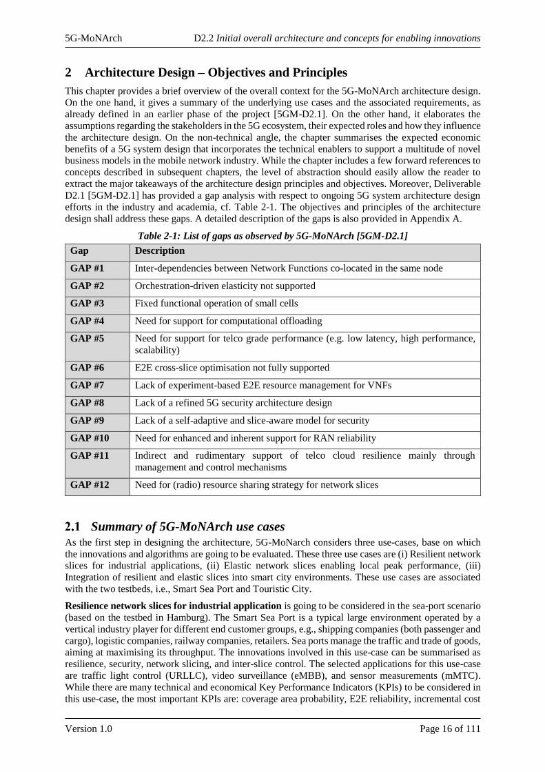
Table 2-1: List of gaps as observed by 5G-MoNArch [5GM-D2.1]
Gap Description
GAP #1 Inter-dependencies between Network Functions co-located in the same node
GAP #2 Orchestration-driven elasticity not supported
GAP #3 Fixed functional operation of small cells
GAP #4 Need for support for computational offloading
GAP #5 Need for support for telco grade performance (e.g. low latency, high performance,
scalability)
GAP #6 E2E cross-slice optimisation not fully supported
GAP #7 Lack of experiment-based E2E resource management for VNFs
GAP #8 Lack of a refined 5G security architecture design
GAP #9 Lack of a self-adaptive and slice-aware model for security
GAP #10 Need for enhanced and inherent support for RAN reliability
GAP #11 Indirect and rudimentary support of telco cloud resilience mainly through
management and control mechanisms
GAP #12 Need for (radio) resource sharing strategy for network slices
Summary of 5G-MoNArch use cases
As the first step in designing the architecture, 5G-MoNarch considers three use-cases, base on which
the innovations and algorithms are going to be evaluated. These three use cases are (i) Resilient network
slices for industrial applications, (ii) Elastic network slices enabling local peak performance, (iii)
Integration of resilient and elastic slices into smart city environments. These use cases are associated
with the two testbeds, i.e., Smart Sea Port and Touristic City.
Resilience network slices for industrial application is going to be considered in the sea-port scenario
(based on the testbed in Hamburg). The Smart Sea Port is a typical large environment operated by a
vertical industry player for different end customer groups, e.g., shipping companies (both passenger and
cargo), logistic companies, railway companies, retailers. Sea ports manage the traffic and trade of goods,
aiming at maximising its throughput. The innovations involved in this use-case can be summarised as
resilience, security, network slicing, and inter-slice control. The selected applications for this use-case
are traffic light control (URLLC), video surveillance (eMBB), and sensor measurements (mMTC).
While there are many technical and economical Key Performance Indicators (KPIs) to be considered in
this use-case, the most important KPIs are: coverage area probability, E2E reliability, incremental cost
5G-MoNArch D2.2 Initial overall architecture and concepts for enabling innovations
Version 1.0 Page 17 of 111
(i.e., the extra cost to offer higher level of reliability and resilience) per GB, and incremental revenue
per GB.
Elastic network slicing enabling local peak performance: is going to executed in the Touristic City
(Turin) testbed related verification scenario. The Touristic City (located in Turin) testbed represnets a
typical case of futre advanced multimeda service deliveray in a Touristic City. The main innovations
involved in this use-case are computaitonally-elastic network functions, cloud-enabled protocol stack,
and slice-aware elasticity. In addtion to torutistic city senarios, a combined smart city (for simplicity
restricted to eMBB) and sea-port related scenario in Hamburg with focus on cost efficiency gains by
elastic network slices fulfilling the smart city as well as demand hot spot service definitions. Since
elestice management of network resources is the main goal in this use-case, the main KPIs among all
the KPIs to focus on are: cost efficiency gain, incremental cost per GB, and incremental revenue per
GB.
Integration of resilient and elastic slices into smart city environments is executed in the Hamburg
verification scenario considering a wider range of tenants than was the case in the first use-case. These
tenants now include those for smart city services as well as for the Smart Sea Port services (investigated
in evaluation case 1) to understand how the benefits of the 5G-MoNArch enablers change for scenarios
of different scales and scope of services. In addition, the localised temporary hotspots of demand from
evaluation case 2 are combined in this scenario to understand how accommodating these might be
impacted by trying to utilise network elasticity on a multi-service network. In this case all performance
profiles of the former cases are applied in order to investigate benefits of and flexibility introduced due
to 5G-MoNArch enablers in a combined scenario. The integration of resilient and elastic network slices
into future smart city environments will allow for verification and demonstration of the full potential of
5G-MoNArch enablers within fully fledged future 5G network architectures. The important KPIs for
this use-case are coverage area probability, E2E reliability, and cost efficiency gain.
Summary of 5G-MoNArch requirements
One important step in defining the 5G-MoNArch architecture has been to list and detail all the necessary
requirements. In this section, an overview of the requirements defined so far in the project is given. The
reader can find more details in deliverable D6.1 [5GM-D6.1]. The requirements are grouped in four
categories: general, resilience and security, resource elasticity, and techno-economic requirements.
• The general requirements group is a consolidated version of general requirements taken from
the 5GPPP Phase 1 projects, industry forums and SDOs. These requirements can be in turn
further classified into generic, network slicing, RAN-related, capacity exposure, and security.
• The second set of requirements relates to resilience and security. More specific to the 5G-
MoNArch project, they are further classified into protection, detection, and reaction.
o Protection refers to how efficient is the network when protecting itself from
encountering malfunctions; radio link outage probability should be minimal in order to
achieve the required high network reliability and availability.
o The Detection group deals with exposing network faults and malfunctions as well as
security threads critical to 5G systems.
o Proper Reaction should occur to malfunctions or security attacks to ensure the
performance of the 5G systems.
• The third set of requirements is related to resource elasticity. The list of requirements is:
o Elastic VNFs should adapt to variations in resource availability, avoiding abrupt
degradation in the performance.
o An elastic network slice should match available resources to instantaneous demand by
gracefully adapting itself.
o At the infrastructure level, the number of network slices and the resources reserve to
them should be flexible to allow for more network slices on the same infrastructure
• Finally, the last set of requirements refers to the techno-economic evaluation. They are related
to the commercial benefit of the 5G-MoNArch architecture. They consist of four requirements:
o Improve user experience on existing services to improve willingness to pay and drive
up revenues from consumers.
5G-MoNArch D2.2 Initial overall architecture and concepts for enabling innovations
Version 1.0 Page 18 of 111
o Enable service providers to provide a greater variety of services, to access higher value
business-to-business (B2B) rather than purely business-to-consumer (B2C) revenues
for their wireless services
o Support a layered multi-tenant ecosystem to allow service providers to maximise value
from their services and minimise costs.
o Improve network utilisation in order to provide a larger number of wireless services.
Assuming all the above requirements are achieved, they will show the long term commercial viability
of mobile networks implementing the 5G-MoNArch architecture.
5G-MoNArch ecosystem
The 5G-MoNArch architecture will represent a change in the current mobile network stakeholder
ecosystem. Mobile network operators (MNOs) will change from a vertically integrated model, where
they own the spectrum, antenna and core network sites and equipment, to a layered model where each
layer might be managed or implemented by a different stakeholder. This new situation arises from the
5G virtualised network capability as proposed by 5G-MoNArch. Besides that, the seamless integration
of new verticals into the mobile ecosystem, opportunities for new revenues streams for mobile service
providers, and enable realisation of benefits to society more generally would also ideally take place.
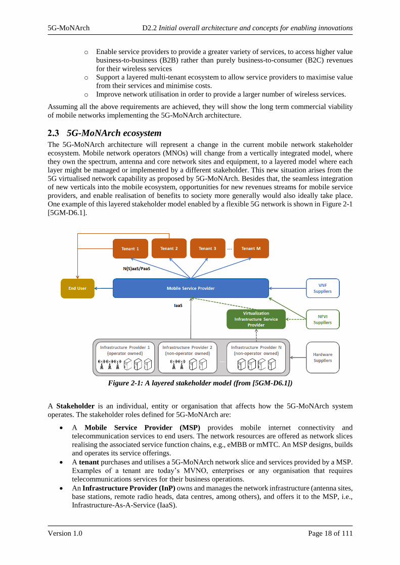
One example of this layered stakeholder model enabled by a flexible 5G network is shown in Figure 2-1
[5GM-D6.1].
Figure 2-1: A layered stakeholder model (from [5GM-D6.1])
A Stakeholder is an individual, entity or organisation that affects how the 5G-MoNArch system
operates. The stakeholder roles defined for 5G-MoNArch are:
• A Mobile Service Provider (MSP) provides mobile internet connectivity and
telecommunication services to end users. The network resources are offered as network slices
realising the associated service function chains, e.g., eMBB or mMTC. An MSP designs, builds
and operates its service offerings.
• A tenant purchases and utilises a 5G-MoNArch network slice and services provided by a MSP.
Examples of a tenant are today’s MVNO, enterprises or any organisation that requires
telecommunications services for their business operations.
• An Infrastructure Provider (InP) owns and manages the network infrastructure (antenna sites,
base stations, remote radio heads, data centres, among others), and offers it to the MSP, i.e.,
Infrastructure-As-A-Service (IaaS).
5G-MoNArch D2.2 Initial overall architecture and concepts for enabling innovations
Version 1.0 Page 19 of 111
• A Mobile Network Operator (MNO) operates and owns the mobile network, combining the
roles of MSP and InP.
• A Virtualisation Infrastructure Service Provider (VISP) may exist, responsible for
designing, building and operating a virtualisation infrastructure on top of the InP services, and
offering its infrastructure service to the MSP.
• A hardware (HW) supplier offers hardware to the InPs (server, antenna, cable …)
• A NFV Infrastructure (NFVI) supplier provides the corresponding NFV infrastructure to its
customers, i.e. to the VISP and/or directly to the MSP
• A VNF supplier offers virtualised software (SW) components to the MSP.
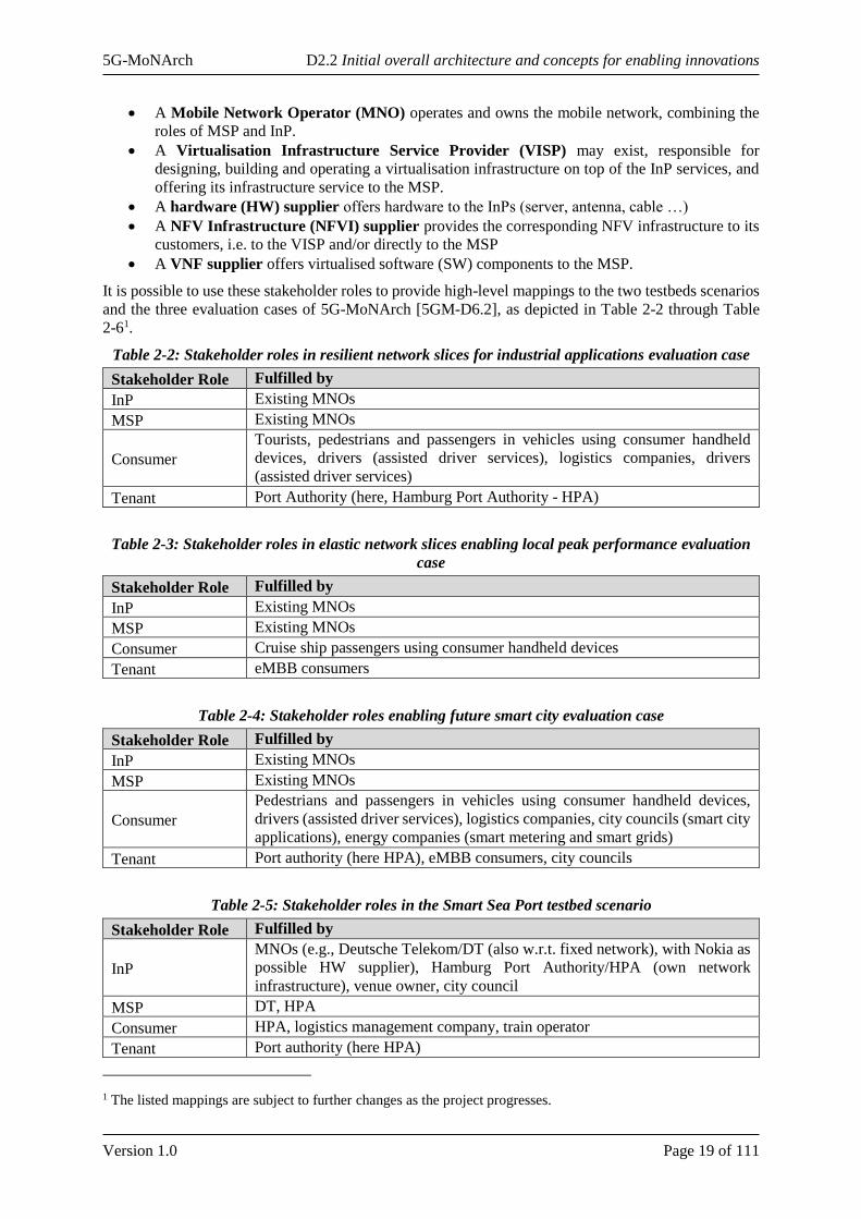
It is possible to use these stakeholder roles to provide high-level mappings to the two testbeds scenarios
and the three evaluation cases of 5G-MoNArch [5GM-D6.2], as depicted in Table 2-2 through Table
2-61.
Table 2-2: Stakeholder roles in resilient network slices for industrial applications evaluation case
Stakeholder Role Fulfilled by
InP Existing MNOs
MSP Existing MNOs
Consumer
Tourists, pedestrians and passengers in vehicles using consumer handheld
devices, drivers (assisted driver services), logistics companies, drivers
(assisted driver services)
Tenant Port Authority (here, Hamburg Port Authority - HPA)
Table 2-3: Stakeholder roles in elastic network slices enabling local peak performance evaluation
case
Stakeholder Role Fulfilled by
InP Existing MNOs
MSP Existing MNOs
Consumer Cruise ship passengers using consumer handheld devices
Tenant eMBB consumers
Table 2-4: Stakeholder roles enabling future smart city evaluation case
Stakeholder Role Fulfilled by
InP Existing MNOs
MSP Existing MNOs
Consumer
Pedestrians and passengers in vehicles using consumer handheld devices,
drivers (assisted driver services), logistics companies, city councils (smart city
applications), energy companies (smart metering and smart grids)
Tenant Port authority (here HPA), eMBB consumers, city councils
Table 2-5: Stakeholder roles in the Smart Sea Port testbed scenario
Stakeholder Role Fulfilled by
InP
MNOs (e.g., Deutsche Telekom/DT (also w.r.t. fixed network), with Nokia as
possible HW supplier), Hamburg Port Authority/HPA (own network
infrastructure), venue owner, city council
MSP DT, HPA
Consumer HPA, logistics management company, train operator
Tenant Port authority (here HPA)
1 The listed mappings are subject to further changes as the project progresses.
5G-MoNArch D2.2 Initial overall architecture and concepts for enabling innovations
Version 1.0 Page 20 of 111
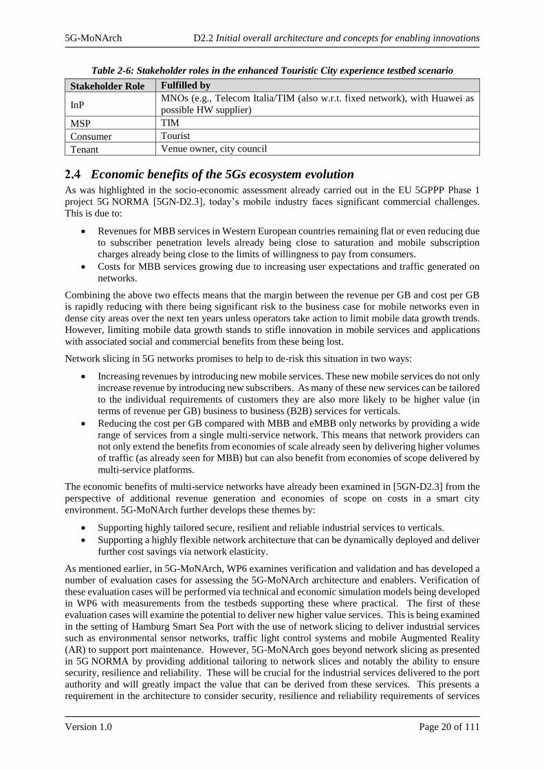
Table 2-6: Stakeholder roles in the enhanced Touristic City experience testbed scenario
Stakeholder Role Fulfilled by
InP MNOs (e.g., Telecom Italia/TIM (also w.r.t. fixed network), with Huawei as
possible HW supplier)
MSP TIM
Consumer Tourist
Tenant Venue owner, city council
Economic benefits of the 5Gs ecosystem evolution
As was highlighted in the socio-economic assessment already carried out in the EU 5GPPP Phase 1
project 5G NORMA [5GN-D2.3], today’s mobile industry faces significant commercial challenges.
This is due to:
• Revenues for MBB services in Western European countries remaining flat or even reducing due
to subscriber penetration levels already being close to saturation and mobile subscription
charges already being close to the limits of willingness to pay from consumers.
• Costs for MBB services growing due to increasing user expectations and traffic generated on
networks.
Combining the above two effects means that the margin between the revenue per GB and cost per GB
is rapidly reducing with there being significant risk to the business case for mobile networks even in
dense city areas over the next ten years unless operators take action to limit mobile data growth trends.
However, limiting mobile data growth stands to stifle innovation in mobile services and applications
with associated social and commercial benefits from these being lost.
Network slicing in 5G networks promises to help to de-risk this situation in two ways:
• Increasing revenues by introducing new mobile services. These new mobile services do not only
increase revenue by introducing new subscribers. As many of these new services can be tailored
to the individual requirements of customers they are also more likely to be higher value (in
terms of revenue per GB) business to business (B2B) services for verticals.
• Reducing the cost per GB compared with MBB and eMBB only networks by providing a wide
range of services from a single multi-service network. This means that network providers can
not only extend the benefits from economies of scale already seen by delivering higher volumes
of traffic (as already seen for MBB) but can also benefit from economies of scope delivered by
multi-service platforms.
The economic benefits of multi-service networks have already been examined in [5GN-D2.3] from the
perspective of additional revenue generation and economies of scope on costs in a smart city
environment. 5G-MoNArch further develops these themes by:
• Supporting highly tailored secure, resilient and reliable industrial services to verticals.
• Supporting a highly flexible network architecture that can be dynamically deployed and deliver
further cost savings via network elasticity.
As mentioned earlier, in 5G-MoNArch, WP6 examines verification and validation and has developed a
number of evaluation cases for assessing the 5G-MoNArch architecture and enablers. Verification of
these evaluation cases will be performed via technical and economic simulation models being developed
in WP6 with measurements from the testbeds supporting these where practical. The first of these
evaluation cases will examine the potential to deliver new higher value services. This is being examined
in the setting of Hamburg Smart Sea Port with the use of network slicing to deliver industrial services
such as environmental sensor networks, traffic light control systems and mobile Augmented Reality
(AR) to support port maintenance. However, 5G-MoNArch goes beyond network slicing as presented
in 5G NORMA by providing additional tailoring to network slices and notably the ability to ensure
security, resilience and reliability. These will be crucial for the industrial services delivered to the port
authority and will greatly impact the value that can be derived from these services. This presents a
requirement in the architecture to consider security, resilience and reliability requirements of services
5G-MoNArch D2.2 Initial overall architecture and concepts for enabling innovations
Version 1.0 Page 21 of 111
and to be able to flexibly instantiate network slices that include the appropriate network functions and
infrastructure mapping to deliver against these requirements.
5G-MoNArch also promises to provide further cost benefits by providing not only a virtualised network
with a separation between hardware and software elements but also to be able to make the most of this
separation by dynamically instantiating and deploying network elements as demand on the network
dictates. This is particularly applicable for ensuring that networks are not over dimensioned to deal with
temporary demand hotspots. The network elasticity features of 5G-MoNArch will be assessed in the
second evaluation case in the context of large cruise ships with up to 4,000 passengers arriving in
Hamburg port and generating a demand hotspot. To enable these cost efficiencies from network
elasticity the 5G-MoNArch architecture and protocol stack must support highly dynamic slice
instantiation and re-configuration of network slices. This flexibility requirement extends beyond the
baseband processing elements of the network to antenna sites and radio resource usage also as this is
where the bulk of network costs are currently incurred.
Economies of scale and scope benefits will be revisited in 5G-MoNArch under the third evaluation case
where the scenario of serving an industrial tenant in the form of Hamburg Port Authority is combined
with also delivering smart city services to other tenants such as a city council from the start point of an
existing eMBB network. This combined scenario will also include the demand hotspots from evaluation
case 2 and investigate the cost savings of network elasticity in this wider scenario with a greater range
and diversity of services.
A final requirement from the economic perspective for the 5G-MoNArch architecture is ecosystem
related. De-coupling of the network service from the infrastructure in virtualised networks not only
promises improved cost efficiencies via flexibility and elasticity, as indicated above, but also presents
opportunities for new players in the ecosystem as per the tiered stakeholder model introduced in
5G NORMA and re-emphasised in 5G-MoNArch Deliverable D6.1 [5GM-D6.1]. However, to enable
this new stakeholder model open interfaces and harmonised network function specifications are needed.
Feedback from existing MNOs considering the transition to virtualised networks indicates that they
remain sceptical that VNFs, orchestrators etc. will truly be plug and play across a range of infrastructure
providers. There is therefore a challenge for 5G-MoNArch to address this concern.
5G-MoNArch D2.2 Initial overall architecture and concepts for enabling innovations
Version 1.0 Page 22 of 111
3 5G-MoNArch Initial Overall Architecture
This chapter details the 5G-MoNArch initial2 architecture reference model and describes the funda-
mental design aspects: (i) E2E slicing support across different technological, network, and
administrative domains, (ii) the envisioned service-based architecture (SBA), and (iii) split of control
plane and user plane (CP/UP) and the resulting impact on CN and (R)AN network functions. Starting
with the overall architecture design which elaborates on the fundamental structuring into network layers
and domains, the chapter further depicts where the architecture relies on already existing architecture
components, e.g., from 3GPP or ETSI NFV. Further, novel network functions for core and radio access
network as well as innovative management and orchestration functions introduced by 5G-MoNArch are
mapped into the architecture, thus completing the overall picture of the 5G-MoNArch architecture. The
detailed role of network functions, particularly their mutual interaction to enable the 5G-MoNArch
innovations, is then presented in Chapter 4.
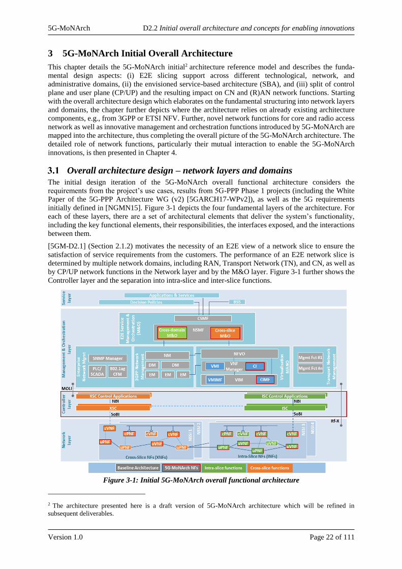
Overall architecture design – network layers and domains
The initial design iteration of the 5G-MoNArch overall functional architecture considers the
requirements from the project’s use cases, results from 5G-PPP Phase 1 projects (including the White
Paper of the 5G-PPP Architecture WG (v2) [5GARCH17-WPv2]), as well as the 5G requirements
initially defined in [NGMN15]. Figure 3-1 depicts the four fundamental layers of the architecture. For
each of these layers, there are a set of architectural elements that deliver the system’s functionality,
including the key functional elements, their responsibilities, the interfaces exposed, and the interactions
between them.
[5GM-D2.1] (Section 2.1.2) motivates the necessity of an E2E view of a network slice to ensure the
satisfaction of service requirements from the customers. The performance of an E2E network slice is
determined by multiple network domains, including RAN, Transport Network (TN), and CN, as well as
by CP/UP network functions in the Network layer and by the M&O layer. Figure 3-1 further shows the
Controller layer and the separation into intra-slice and inter-slice functions.
Figure 3-1: Initial 5G-MoNArch overall functional architecture
2 The architecture presented here is a draft version of 5G-MoNArch architecture which will be refined in
subsequent deliverables.
5G-MoNArch D2.2 Initial overall architecture and concepts for enabling innovations
Version 1.0 Page 23 of 111
The Service layer comprises Business Support Systems (BSS), business-level Policy and Decision
functions, and further applications and services operated by a tenant or other external entities. These
functions of the Service layer interact with the Management & Orchestration (M&O) layer via the
CSMF, see below.
The Management & Orchestration layer is composed of the M&O functions from different network,
technology, and administration domains (3GPP public mobile network management, ETSI Network
Function Virtualisation (NFV) Management and Orchestration (MANO) [ETSI NFV13], ETSI Multi-
access Edge Computing functions [ETSI MEC16], management functions of transport networks (TNs)
and private enterprise networks). Further, the M&O layer comprises the end-to-end M&O sublayer
hosting the Network Slice Management Function (NSMF) and Communication Service Management
Function (CSMF) that manage network slices and communications services, respectively, across
multiple management and orchestration domains in a seamless manner. In the so-called Virtualisation
MANO domain, the ETSI NFV MANO architecture for lifecycle management (LCM) of Virtual
Machines (VMs) is extended towards LCM of virtualisation containers (e.g., Docker). Therefore, it
comprises, besides the ETSI NFV components, corresponding functions for LCM of containers.
Therefore, the Virtualised Network Function Manager (VNFM) has according components for virtual
machine infrastructure (VMI) and container infrastructure (CI). Similarly, the Virtualised Infrastructure
Manager (VIM) contains a VMI Management Function (VMIMF) and a CI Management Function
(CIMF). NFV Orchestrator (NFVO) provides the dispatching functionality. Further, the layer
accommodates 3GPP network management function, such as, Element and Domain Managers (EM and
DM) and Network Management (NM) functions. Such functions would also implement ETSI NFV
MANO reference points to the VNFM and the NFVO. The CSMF transforms consumer-facing service
descriptions into resource-facing service descriptions (and vice versa) and therefore works as an
intermediary function between the Service layer and the NSMF. The NSMF splits service requirements
as received from CSMF and coordinates (negotiates) with multiple management domains for E2E
network slice deployment and operation. Aa a major 5G-MoNArch novelty, NSMF further incorporates
a Cross-slice M&O function for inter-slice management (e.g., common context between different
slices/tenants, inter-slice resource brokering for cross-slice resource allocation, particularly in the case
of shared NFs, etc.). In contrast, the Cross-domain M&O function works on strictly intra-slice level, but
across multiple network and technology domains. The M&O layer performs the management tasks on
Network Slice Instances (NSI), which are uniquely identified by an NSI identifier. An NSI may be
further associated with one or more Network Slice Subnet Instances (NSSI). The details are further
described in Sections 3.3.3 and 5.1.
The Network layer comprises the VNFs and physical NFs (PNFs) of both control plane (i.e., cVNF,
cPNF) and user plane (i.e., uVNF, uPNF). NFs can include, for example, 3GPP Rel. 15 control plane
(CP) functions (AMF, SMF, AUSF, RRC, etc.) and user plane (UP) functions (e.g., UPF, PDCP, etc.)
or novel NFs developed in the project, e.g. for resource elasticity, resilience, and security. Generally,
the 5G-MoNArch Network layer can comprise different CP/UP architectures, i.e., also a 4G mobile
network with EUTRAN and EPC functions could constitute an instance of the Network layer. Interfaces
towards the M&O layer are provided via the Itf-X reference point. It is an evolution of the 3GPP Itf-S
interface between Element Manager (EM) and Network Element (NE), e.g., eNB, and facilitates
domain-specific fault, configuration, accounting, performance, and security (FCAPS) management as
well as domain-agnostic LCM procedures. For associating a UE to the correct NSI, the Network layer
uses the Single Network Slice Selection Assistance Information (S-NSSAI), which is provided by the
UE. Moreover, the CN part of the CP in the network layer is realised as a service-based architecture
(SBA) [3GPP TS 23.501]. Further details of CN functionality, slice identification, and SBA are
explained in Sections 3.2.2 and 3.3.2, details on the 5G-MoNArch RAN architecture are shown in
Sections 3.2.1 and 3.3.1.
The Controller layer realises the software-defined networking concepts [ONF14], extends them to
mobile networks, and therefore accommodates two controller types:
(1) the Cross-slice Controller (XSC), e.g., a RAN controller (cf. Section 4.5.1) for the control of
Cross-slice Network Functions (XNFs) that are shared by multiple network slices, and
5G-MoNArch D2.2 Initial overall architecture and concepts for enabling innovations
Version 1.0 Page 24 of 111
(2) the Intra-slice Controller (ISC), e.g., a CN controller for Intra-slice Network Function (INFs)
within a dedicated CN-NSSI.
These controllers expose a northbound interface (NBI) towards control applications and a southbound
interface (SoBI) towards VNFs and PNFs in the Network layer. Interfaces towards the M&O layer are
provided via the MOLI reference point. The Controller layer facilitates the concept of mobile network
programmability. Generally, software-defined networking (SDN) splits between logic and agent for
any functionality in the network. This means that the NFs are split into the decision logic hosted in a
control application and the actual NF in the Network layer (usually a uPNF or uVNF) that executes the
decision. In other words, for the given uVNF or uPNF, the according cPNf or cVNF would disappear.
The controller resides “between” application and NF and abstract from specific technologies and
implementations realised by the NF, thus decoupling the control application from the controlled NF, cf.
Figure 3-1. 5G-MoNArch investigates the applicability of this paradigm, focusing on the concepts for
elasticity (WP4) and resiliency (WP3). If no such split between control logic and agent is applied, i.e.,
the cPNFs and cVNFs incorporate both, the Controller layer disappears. In this sense, it is an optional
layer of the 5G-MoNArch architecture.
Moreover, it is worth mentioning that the interfaces depicted between the different layers will be further
defined within 5G-MoNArch future work. In particular, this comprises the interfaces from M&O layer
to Controller layer and Network layer, respectively. Figure 3-1 implicitly illustrates three fundamental
design aspects that shall be followed in the 5G-MoNArch architecture:
(1) Support for E2E network slicing: The architecture allows for combining different options
of slicing support across M&O and Network layers for each slice instance. The first supported
option includes slice-specific functions, i.e., each slice may incorporate dedicated and possibly
customised functions that are not shared with others. The second option includes the possibility
to operate functions (or function instances) that are shared by multiple slices and have the
capability to address requirements from multiple slices in parallel. Figure 3-1 depicts this split
into common or so-called inter-slice functions and dedicated (intra-slice) functions. This split
can be maintained in the M&O layer, the Network layer, as well as the optional Controller
layer, i.e., dedicated NFs may be controlled and managed by the tenant’s own instance of ISC
and M&O layer functions. Shared functions are usually operated by the Mobile Network
Operator (MNO) or the Mobile Service Provider (MSP) according to the stakeholder model
defined in D6.1. The MNO (together with potential third-party infrastructure providers) is also
in charge of managing the infrastructure. The policies regarding the utilisation of shared
functions, particularly the resource allocation to active slices, are determined by the Cross-
slice M&O function, and communicated towards the respective Network layer functions for
further enforcement. Finally, the third option is to not only have slice-dedicated NFs but to
additionally assign the associated infrastructure hardware resources (HW), including
spectrum, exclusively to a single slice. The slice-specific functions and shared functions in
one logical slice are bind together by the network slice identifier at the network layer. More
details on how the Network layer performs network slice selection is described in Sections 3.2
and 0.
(2) Service-based architecture (SBA): The service-based interaction between core network CP
NFs provides a set of features and associated advantages. Among others, NFs can be realised
in a stateless manner since such state-related data (e.g., session data) are shared via a message
bus, sometimes referred to as data bus. SBA facilitates the design of modularised NFs, uniform
interaction procedures between NFs (e.g., NFs can offer their functionality as a service to other
NFs), unified authentication framework between NFs, and concurrent access to services.
Further details on SBA can be found in Section 3.3.2.
(3) Split of control and user plane: 5G-MoNArch applies a consistent split of control plane and
user plane throughout all network domains, including RAN, CN, and TN. Among others, this
allows for hosting associated CP and UP NFs in different locations and also facilitates to
aggregate CP and UP NFs differently. The split further allows independent scalability and
evolution of NFs.

5G-MoNArch D2.2 Initial overall architecture and concepts for enabling innovations
Version 1.0 Page 25 of 111
Moreover, the network architecture needs to support the mapping of resilience, reliability, and security
requirements (cf. [5GM-D3.1]) as defined by the MNO or a vertical enterprise to concrete network slice
instances and network slice operation procedures. Such functionality is provided by CSMF, which
extends existing slice templates with further deployment, management, orchestration, and control
instructions for specialised NFs. These NFs may exist within different layers of the architecture. For
example, a set of functions for RAN reliability, realising the architectural support for multi-connectivity,
are placed in the Network layer and in the Controller layer for increasing the reliability level in the RAN
for services such as ultra-reliable and/or ultra-low latency. Further, for distributed and more robust
security solutions, distributed/local security functions provide fundamental access control capabilities
in a ‘standalone’ manner, i.e., without permanent connectivity to the central cloud. Further details on
how the overall architecture design supports WP3 innovations are depicted in Section 5.3.1.1.
Temporal and spatial traffic fluctuations may require that the network re-allocates available resources
as needed. It is referred to this flexibility as resource elasticity, which includes the ability of NFs (and
network slices as a whole) to scale resources according to the demand and to gracefully downscale the
network operation when only insufficient resources are available. This is addressed by WP4 within
5G-MoNArch. Two major challenges comprise the short-timescale RAN functions operate on (when
compared to those of cloud LCM solutions) and the limited availability of cloud resources at the edge,
preventing a major exploitation of multiplexing gains. Therefore, the first challenge is tackled by a
cloud-enabled (RAN) protocol stack that eliminates cross-layer dependencies as much as possible. For
the second challenge, resource orchestration and LCM functions in the 5G-MoNArch architecture must
support computational elasticity, such as relocating VNFs between different edge clouds and potentially
between different network domains, also taking into account transport network capacity, particularly
between edge cloud and antenna sites. Such “orchestration-driven elasticity” is facilitated, among others,
by the cross-domain M&O function. Moreover, “slice-aware elasticity” is realised by cross-slice M&O
functions in order to dynamically share computational and communications resources across slices,
within the constraints of the slice requirements. Further details on novel elasticity mechanisms and their
impact on the overall architecture design can be found in Section 5.3.2.1.
Relationship with standards and standardisation roadmap
3.2.1 Radio access network
A baseline architecture including the RAN protocol stack and the essential functional elements has been
provided in D2.1 [5GM-D2.1]. Therein, it is shown that a fundamental support for network slicing is
provided in the RAN. From the specification perspective, 3GPP Release 15 for next generation-RAN
(NG-RAN) is to be frozen by the time of the publication of this deliverable [3GPP-RP180554]3. This
specification comprises slicing awareness in RAN via NSSAI including one or more S-NSSAIs, which
allow to uniquely identify a network slice [3GPP TS 38.300]. While the fundamental slicing support is
achieved by Release 15, e.g., granularity of slice awareness and network slice selection, various
enhancements and optimisation can be considered for future releases. Such enhancements may imply,
for example, specification-relevant signalling changes and implementation-dependent algorithms, e.g.,
related to RM between slices. The 5G-MoNArch approach aims at both types of enhancements, where
novel RAN components and interfaces are highlighted in Section 3.3.1.
In principle, network slicing offers additional degree of flexibility, where NFs can be tailored according
to the requirements of slice tenants. To this end, it can be expected that different tenants can have vastly
changing needs which can be categorised under three levels, as illustrated in Figure 3-2 [GSA WP17].
On one end, some of the slice tenants may only require a performance differentiation, e.g., in terms of
Quality of Service (QoS) requirements, such as latency and data rate, which can be extended by further
Service Level Agreement (SLA) requirements, such as number of connections for a given time and
location. On the other end, slice tenants can require different management functionality, e.g., a self-
operation of the network services (NSs), such as VNF deployment, monitoring, and fault management
3 A so-called late drop of Release 15, which includes further architecture options, is planned to be frozen by the
end of 2018.

5G-MoNArch D2.2 Initial overall architecture and concepts for enabling innovations
Version 1.0 Page 26 of 111
with dedicated network deployment. In addition, differentiation can be partially on a functional level,
where customised NFs can be introduced by the slice tenants, such as customised security and isolation.
Figure 3-2: High-level classification of the slice tenant requirements [GSA WP17]
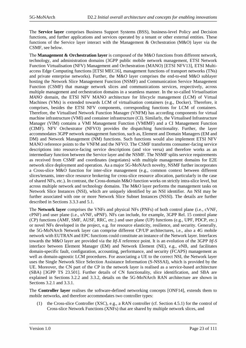
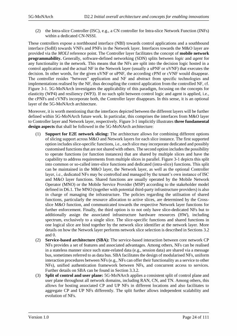
Accordingly, slice tenant requirements can be supported by different network slicing realisation variants
as depicted in Figure 3-3 [5GM-D2.1]:
• In the first realisation variant (L0), an independent operation can be realised by a dedicated
network, e.g., in case of public safety or railway communications.
• In the second realisation variant (L1), the slices may be allocated with dedicated spectrum,
where multiple slices can share the baseband processing and antennas.
• A third possible realisation variant (L2) can be to share spectrum dynamically among different
network slices, making the spectrum allocation on a time slot basis or on a semi-persistent way.
• A fourth realisation variant (L3) is to share the whole RAN protocol stack by slices where SLA
differentiation can be performed with QoS enforcement. In particular, in line with the latest 5G
specification, for an NSI one or more Protocol Data Unit (PDU) sessions can be established,
where a PDU session belongs to one and only one specific NSI [3GPP TS 23.501]. Further,
RAN maps packets belonging to different PDU sessions to different data radio bearers (DRBs),
where within a PDU session there can be one or more QoS flows [3GPP TS 38.300]. On this
basis, the RAN treatment of different network slices can be in terms of radio resource
management (RRM) schemes performed based on the QoS profiles of QoS flows mapped onto
the respective DRBs, where QoS profiles can include performance characteristics, e.g., packet
delay budget and packet error rate, and allocation and retention priority (ARP).
• The last two variants do not only share the RAN among the various slices but also the TN in L4
and both the TN and CN in L5.
The choice toward the slicing realisation variants described above (involving the design of the slice-
tailored NFs at different levels) depends on the needs of the slice tenants and how these needs can be
realised on the RAN side. Thus, it is expected that different realisation variants or combinations thereof
(e.g., partly shared core NFs and partly slice-specific core NFs) can co-exist. Yet, it seems that the
variants L0, L1 and L4 may be realised first in 5G deployments. In case high isolation is required
(variants L0 and L1 in Figure 3-3), all RAN protocol stack functions can be tailored according to the
slice requirements. In such cases, for instance, each slice can run its tailored dynamic scheduler as an
intra-slice control function. In realisation variants, e.g., L4 in Figure 3-3, where the whole RAN protocol
stack is shared by different network slices, the control functions are of the cross-slice form. Under the
light of the above discussion, part of the cross-slice control functions, e.g., slice-aware RRM, can be
implemented as intra-slice control functions when a high-isolation realisation variant is considered. It is
worth re-emphasising that even though the whole RAN protocol stack is shared by different network
slices, slice-specific performance requirements can be fulfilled with appropriate QoS enforcement, as
discussed under the L4 variant above.
In a further dimension, especially slow-timescale RAN control functions can be implemented as
applications running in the Controller Layer shown in Section 3.1 and further described in Section 3.3.1.
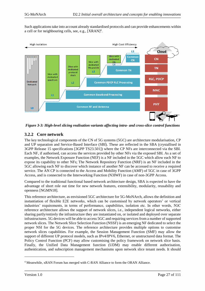
5G-MoNArch D2.2 Initial overall architecture and concepts for enabling innovations
Version 1.0 Page 27 of 111
Such applications take into account already standardised protocols and can provide enhancements within
a cell or for neighbouring cells, see, e.g., [XRAN]4.
Figure 3-3: High-level slicing realisation variants affecting intra- and cross-slice control functions
3.2.2 Core network
The key technological components of the CN of 5G systems (5GC) are architecture modularisation, CP
and UP separation and Service-Based Interface (SBI). These are reflected in the SBA (crystallised in
3GPP Release 15 specifications [3GPP TS23.501]) where the CP NFs are interconnected via the SBI.
Each NF, if authorised, can access the services provided by other NFs via the exposed SBI. As a set of
examples, the Network Exposure Function (NEF) is a NF included in the 5GC which allow each NF to
expose its capability to other NFs; The Network Repository Function (NRF) is an NF included in the
5GC allowing each NF to discover which instance of another NF can be accessed to receive a required
service. The AN CP is connected to the Access and Mobility Function (AMF) of 5GC in case of 3GPP
Access, and is connected to the Interworking Function (N3IWF) in case of non-3GPP Access.
Compared to the traditional functional based network architecture design, SBA is expected to have the
advantage of short role out time for new network features, extensibility, modularity, reusability and
openness [NGMN18].
This reference architecture, as envisioned 5GC architecture for 5G-MoNArch, allows the definition and
instantiation of flexible E2E networks, which can be customised by network operators’ or vertical
industries’ requirements, in terms of performance, capabilities, isolation etc. In other words, 5GC
reference architecture allows the support of network slices, i.e., independent logical networks, either
sharing partly/entirely the infrastructure they are instantiated on, or isolated and deployed over separate
infrastructures. 5G devices will be able to access 5GC and requiring services from a number of supported
network slices. The Network Slice Selection Function (NSSF) is an emerging NF dedicated to select the
proper NSI for the 5G devices. The reference architecture provides multiple options to customise
network slices capabilities. For example, the Session Management Function (SMF) may allow the
support of different UP protocol models, such as IPv4/IPV6, Ethernet, or unstructured data format. The
Policy Control Function (PCF) may allow customising the policy framework on network slice basis.
Finally, the Unified Data Management function (UDM) may enable different authorisation,
authentication, and subscription management mechanisms upon network slice tenant needs. It should
4 Meanwhile, xRAN Forum has merged with C-RAN Alliance to form the ORAN Alliance.
5G-MoNArch D2.2 Initial overall architecture and concepts for enabling innovations
Version 1.0 Page 28 of 111
also be noted that, thanks to SBI, the reference architecture also provides third parties with the possibility
to influence the network behaviour, extend and customise network slices capabilities via the inclusion
in the system of proprietary non-standard Application Functions (AFs). Using the SBI, the AF is possible
to access services provided by other NFs, as well as to expose theirs services to other NFs, e.g., via NEF.
Despite the foundations for 5GC have been successfully established, the general framework still appear
not entirely mature and seems to be still susceptible to significant technical and conceptual
enhancements. Some key examples of issues still offering a large number of design options and room
for further improvements are:
• The instantiation and selection of NFs for different slices in the infrastructure;
• The specific functional customisation of NFs to address requirements of specific use cases;
• The functional interaction among different network slices.
The 5G-MoNArch core network architecture uses the 3GPP SBA based architecture and network
functions currently defined in Rel. 15 as a baseline. The needed enhancement of the network functions
e.g., AMF, PCF, NSSF, are studied to address several of the gaps listed in Table 2-1.
A separate distinguishing feature of 5GC, compared to previous generation networks, is network
analytics capability embedded in the general framework, via the definition of the Network Data
Analytics function (NWDAF). In short, as per 3GPP Release 15, NWDAF provides 5GC with the ability
to collect and analyse per slice aggregated data, and to aid network optimisation via interaction with
PCF. Albeit included in 3GPP release 15 specification, NWDAF description and capabilities are
extremely rudimental. The exploitation of the full potentials of network analytics and Big Data
technologies requires the clarification and investigation of a number of questions, including:
• What data should be collected by NWDAF and what feedback is expected from NWDAF;
• From which entities and how should the NWDAF collect the data;
• How NWDAF shall collect data on per PLMN and/or per slice and/or per user basis and/or per
session basis;
• How NWDAF shall expose its services, and which NFs may benefit from them;
• How can NWDAF get the data from the NFs/NEs which are not connected to the SBI;
• The granularity of the optimisation to be enabled by NWDAF services, options being:
o Per session basis;
o Per user basis;
o Per slice basis;
o On Inter-slice basis.
5G-MoNArch is investigating the enhancement of the CP/UP procedure (e.g., slice alignment procedure
between RAN and CN) and the architecture (e.g., interfaces and functionality extension of NWDAF,
new functionality to support inter-slice coordination) to address the above issues and questions. The
related innovation elements are described in Section 3.3.2 as InE#2 Inter-slice coordination and InE#3
Inter-slice context sharing and optimisation. The detailed solution and analysis of the innovation
elements in the core network are included in Sections 4.2.1, 4.2.2, and 4.2.3, respectively.
One other aspect is the E2E slice view which needs the alignment of a network slice between the
Network layer and M&O layer. The M&O layer looks at the network slice deployment in a longer time
scale for one tenant/one group of services. The Network layer takes care of the individual user, connects
them to the already deployed NSI by the M&O layer and controls the shorter time scale slice KPIs. Both
layers need to work together to guarantee the Service Level Agreement (SLA).
In the real network deployment, not all network slices are supported over the complete PLMN network,
especially when considering the E2E perspective. 3GPP defines the network slice availability as
following:
“A Network Slice may be available in the whole PLMN or in one or more Tracking Areas of the PLMN.
The availability of a Network Slice refers to the support of the NSSAI in the involved NFs. In addition,
policies in the NSSF may further restrict from using certain Network Slices in a particular TA, e.g.
depending on the HPLMN of the UE.”

5G-MoNArch D2.2 Initial overall architecture and concepts for enabling innovations
Version 1.0 Page 29 of 111
More specifically, the E2E slice availability is decided by the RAN slice capabilities, CN slice
capabilities, the NSI management, network configuration, and also network policies. This brings up the
following issues:
• Whether the current network layer slice selection mechanism in 3GPP is sufficient to address
different deployment scenarios.
• How the Network layer interacts with management layer on individual network slices.
• How to map the customer services to the actual deployed network slice in the operator network.
Since end to end aspects of slice covers from service layer, management and orchestration and network
layer, the enhancements are discussed in different sections e.g., context aware slice selection is covered
in Section 4.2.3, CP/M&O layer per slice interaction is covered in Section 4.2.1, and service to slice
mapping is captured in Section 4.2.2.
3.2.3 Management and orchestration
5G-MoNArch M&O system follow 3GPP guidelines using virtualisation and slicing to fill the
identified gaps (cf. Table 2-1). VNF are aggregated into network slices and foresees automation and
orchestration functions also considering Self Organising Network (SON) algorithms. E2E management
and orchestration is performed at different levels in a coordinated manner. These levels are: service,
network configuration, virtualisation, and transport. 5G-MoNArch M&O layer takes care of this job,
interworking with Control layer and Network layer, to deploy the required NFs and to configure the
appropriate interconnections according to the service and network requirements.
The 5G-MoNArch M&O layer complies with 3GPP specifications that foresee a management system
that coordinates network and slice management and orchestration. Current 5G-MoNArch architecture
explicitly takes into account the interaction with the 3GPP Management Entities dedicated to Network
management and configuration (3GPP Network Management in Figure 3-4). For slice management the
NSMF will implement 3GPP standards for slice management and orchestration.
Figure 3-4: 5G-MoNArch Management & Orchestration layer
In the E2E Service Management & Orchestration sublayer, service requirements are translated into
network requirements by the CSMF. The obtained network requirements are forwarded to the NSMF
which is composed by sub-entities or micro-services, that address the management and orchestration of
each slice (Cross-domain M&O) and the management according to the possible interaction among slices
in terms of resources and features sharing (Cross-slice M&O).
The Management Function defined into 5G-MoNArch E2E Service Management & Orchestration sub-
layer are needed to support E2E cross-slice optimisation allowing simultaneous operation of multiple
network slices. The Management layer, with the interaction of NSMF and NFVO, fits the specific
requirements of each covered service supporting Orchestration-driven elasticity. Analysing performance
and assurance data the management layer orchestrates action at slice level and cross-slice level to
support telco cloud resilience
5G-MoNArch D2.2 Initial overall architecture and concepts for enabling innovations
Version 1.0 Page 30 of 111
The two service-level sub-entities then interact with Domain-Specific Application Management (e.g
3GPP Network Management and ETSI NFV MANO). To fill several of the identified gaps (cf. Table
2-1), the M&O layer has to:
(1) Identify the requested VNFs/PNFs that support the service requirements.
(2) Identify the forwarding graph that links the VNFs/PNFs.
(3) Identify the configuration and policies (e.g. for elasticity) to fulfil the required service and
SLAs.
(4) Identify the most appropriate Network Slice Template (NST) (for network management) and
Network Service Descriptor (NSD) (for VNF deployment).
(5) Identify KPIs for Performance Management (PM) to meet the requested SLAs.
(6) Orchestrate the deployment and activation of the NSI.
(7) Activate PM and Fault Management (FM).
(8) Run PM and FM comparing the data with the defined KPI for the slice.
(9) Activate orchestration to fulfil service changes requests or to meet the SLAs using FM and
PM.
(10) Expose PM and FM data to the customer (if requested).
(11) Orchestration performs the LCM of VNFs and performs the requested action on the transport
part.
The deployment and management of a network slice is performed to fulfil the request of a customer
asking for a Communication Service, 5G-MoNArch M&O layer is coherent with some aspect specified
by 3GPP in [3GPP TS 28.530]. In the following are reposted the 3GPP principles that 5G-MoNArch is
following from [3GPP TS 28.530].
The 5G-MoNArch M&O layer takes care of the LCM of a NSI working with all the other Domain
Specific orchestrators. When providing a communication service, 5G-MoNArch M&O layer has to use
non-3GPP parts (e.g. Transport Network) in addition to the 3GPP managed network components.
Therefore, in order to ensure the performance of a communication service according to the business
requirements of the customer.
5G-MoNArch M&O layer has to coordinate with the management entities of the non-3GPP parts (e.g.,
ETSI MANO system) when preparing a NSI for this service. This coordination may include obtaining
capabilities of the non-3GPP parts and providing the slice specific requirements and other resource
requirements of the non-3GPP parts.
5G-MoNArch M&O layer has to identify the requirements for RAN, CN and non-3GPP parts of a slice
by breaking down the customer requirements into different parts and sending them to the corresponding
management systems, respectively. To support this capability, and according to 3GPP actors and roles,
5G-MoNArch M&O layer introduce the Communication Service Management Function (CSMF).
The coordination may also include related management data exchange between those management
systems and 3GPP management system. As defined by 3GPP, 5G-MoNArch M&O layer manages NSIs
using three new functions:
• Communication Service Management Function (CSMF): this function takes care of the
management of the communication service and translates the requirements related to the
communication service to network slice related requirements.
• Network Slice Management Function (NSMF): responsible for management and orchestration
of NSI. Derives network slice subnet related requirements from network slice related
requirements. Communicates with NSSMF and CSMF.
• Network Slice Subnet Management Function (NSSMF): responsible for management and
orchestration of NSSI. Communicates with the NSMF. NSMF, according to 5G-MoNArch,
could be useful to take care of specific management domains or to aggregate NF from a specific
vendor.
5G-MoNArch approach on slice offering is coherent with the 3GPP definition of Network Slice as a
Service (NSaaS) [3GPP TS 28.530]. NSaaS can be offered by a Communication Service Provider (CSP)
to its Communication Service Customer (CSC) in the form of a communication service. As defined by

5G-MoNArch D2.2 Initial overall architecture and concepts for enabling innovations
Version 1.0 Page 31 of 111
3GPP, 5G-MoNArch M&O comprises the option of exposing some management interface. For 5G-
MoNArch this feature is important to let the customer to operate the slice applying custom LCM and
optimisations.
5G-MoNArch approach on slice offering is also coherent with the 3GPP definition of “Network Slices
as NOP internals” model. Network slices are not part of the CSP service offering and hence are not
visible to CSCs. However, the NOP, to provide support to communication services, may decide to
deploy network slices, e.g. for internal network optimisation purposes. 5G-MoNArch Deliverable D2.1
[5GM-D2.1] identified some gaps that require an improved management and orchestration (M&O)
system in the 5G-MoNArch architecture. The compliancy and enhancement of what defined in 3GPP,
for the management of 5G networks, is the chosen path to fill those gaps (cf. Table 2-1) related to
management and orchestration.
5G-MoNArch ETSI MANO evolution
Network slicing, multi-tenancy and flexibility of supporting different services are the key requirements
that novel 5G systems have to support. 5G-MoNArch architecture has to fulfil these requirements and
provide mechanisms and framework that manage NFs that are shared between network slices or
belonging to different management domains.
Mapping 3GPP network slicing concepts to ETSI NFV framework
5G-MoNArch architecture embeds ETSI NFV MANO orchestration framework besides 3GPP
compliant modules. This includes:
• VIM: Responsible for control and management of NFV Infrastructure (NFVI) compute, storage
and network resources.
• VNFM: Responsible for LCM of VNF instances.
• NFVO: Responsible for the orchestration of NFVI resources and LCM of NSs.
This section briefly describes the ETSI MANO concepts that are used and enhanced in 5G-MoNArch
and how it can coexist along 3GPP compliant M&O modules [3GPP TR 28.801] to support E2E network
slicing.
ETSI NFV Architectural Framework [ETSI NFV13] introduces a concept of NS (network service) as a
set of NFs connected according to one or more forwarding graphs [ETSI NFV16]; it additionally adds
the concept of nested NSs. The NFVO would use the NSD as a template with information used to
manage the lifecycle of an NS. VNF Descriptor (VNFD), on the other hand, is a template describing the
requirements of VNF. It is used by the VNFM for VNF instantiation and by NFVO to orchestrate the
virtualised resources.
[3GPP TR 28.801] describes a model where a network slice contains one or more network slice subnets.
Each network slice subnet can be composed of one or more NFs. Therefore, a NS can be considered as
a network slice subnet in case it contains at least one VNF. Similarly, the network slice blueprint
described by [ETSI NFV13] could be associated with nested NFV NSDs. Additionally,
[3GPP TR 28.801] describes three management functions dealing with network slicing management as
described in Section 3.3.3, i.e. CSMF, NSMF and NSSMF. In reference to the 5G-MoNArch overall
architecture, Cross-domain M&O could be mapped to NSMF while Cross-slice M&O could be either
NSMF or NSSMF as described in Section 3.1
Figure 3-5 shows how these functions could match the NFV MANO model using the Os-Ma-Nfvo
reference point as a way of interaction between 3GPP slicing related management functions and NFV-
MANO. The role of the NSMF and/or NSSMF would be to determine the type of NS, VNF and PNF
that can fulfil the requirements for a NSI or NSSI.
As described in [5GM-D2.1], there are several gaps that need to be addressed in order to properly
interface with NFV-MANO while slice-related management functions are still under definition in 3GPP
SA5 regarding the interaction with NFV MANO.
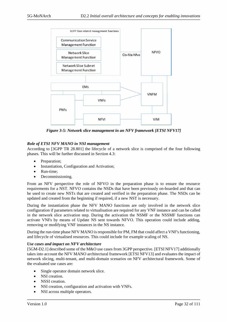
5G-MoNArch D2.2 Initial overall architecture and concepts for enabling innovations
Version 1.0 Page 32 of 111
Figure 3-5: Network slice management in an NFV framework [ETSI NFV17]
Role of ETSI NFV MANO in NSI management
According to [3GPP TR 28.801] the lifecycle of a network slice is comprised of the four following
phases. This will be further discussed in Section 4.3:
• Preparation;
• Instantiation, Configuration and Activation;
• Run-time;
• Decommissioning.
From an NFV perspective the role of NFVO in the preparation phase is to ensure the resource
requirements for a NST. NFVO contains the NSDs that have been previously on-boarded and that can
be used to create new NSTs that are created and verified in the preparation phase. The NSDs can be
updated and created from the beginning if required, if a new NST is necessary.
During the instantiation phase the NFV MANO functions are only involved in the network slice
configuration if parameters related to virtualisation are required for any VNF instance and can be called
in the network slice activation step. During the activation the NSMF or the NSSMF functions can
activate VNFs by means of Update NS sent towards NFVO. This operation could include adding,
removing or modifying VNF instances in the NS instance.
During the run-time phase NFV MANO is responsible for PM, FM that could affect a VNF's functioning,
and lifecycle of virtualised resources. This could include for example scaling of NS.
Use cases and impact on NFV architecture
[5GM-D2.1] described some of the M&O use cases from 3GPP perspective. [ETSI NFV17] additionally
takes into account the NFV MANO architectural framework [ETSI NFV13] and evaluates the impact of
network slicing, multi-tenant, and multi-domain scenarios on NFV architectural framework. Some of
the evaluated use cases are:
• Single operator domain network slice.
• NSI creation.
• NSSI creation.
• NSI creation, configuration and activation with VNFs.
• NSI across multiple operators.
5G-MoNArch D2.2 Initial overall architecture and concepts for enabling innovations
Version 1.0 Page 33 of 111
In case of single operator domain network slices, [ETSI NFV17] suggests that additional functionality
may be needed to support configuring policies, access control, monitoring/SLA rules, and
usage/charging consolidation rules. The specification proposes to add an external entity called Network
Slice Manager that would be responsible of:
• Determining the requirements for NSIs from the description of applications and services by
mapping appropriate features into NSD and VNFD.
• Management of network slice catalogue, network slice and/or sub-network blueprint, and
lifecycle of network slices.
ETSI NFV-MANO system supports and manages the resources of the VNFs, as the NSI can be
composed of VNFs and PNF. In NSI creation use case the MANO is responsible for management of
virtualised resources while 3GPP application takes care of network applications. The NSD contains
requirements for QoS and resources of a network slice. During the instantiation the deployment flavour
is selected during the instantiation. Another use case is derived from [3GPP TR 28.801] and consists of
NSSI creation that is done by NSSMF. This function specifies which NFs and resources are needed. The
NFs can be either VNFs or PNFs. In this case, NFV MANO supports the management of the virtualised
resources. If VNFs are included in NSSI, NSSMF triggers NFV-MANO to instantiate or configure the
VNFs that are needed.
NFV in multi-tenant and multi-domain environment
5G-MoNArch M&O layer has to be extended in order to support multi-tenant and flexible E2E network
slicing. The network slices have to by isolated between each other and capable to run on shared
infrastructure without affecting each other.
Tenants manage the slices in their operative domains by means of NFVO. Each tenant has its own NFVO
that is responsible for resource scheduling in the tenant domain. The resources can belong to different
administrative domains in the infrastructure, so NFVO has to be able to orchestrate resources across
different administrative domains. This is the role of Cross-domain M&O function in 5G-MoNArch.
Cross-domain M&O function is in charge of managing and coordinating NSs between different
management domains. On the other hand, Cross-slice M&O is responsible for common functions
between different slices.
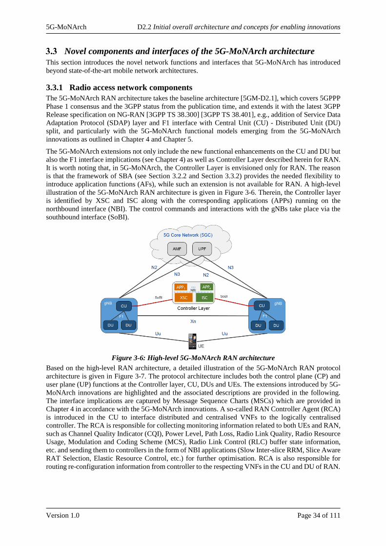
5G-MoNArch D2.2 Initial overall architecture and concepts for enabling innovations
Version 1.0 Page 34 of 111
Novel components and interfaces of the 5G-MoNArch architecture
This section introduces the novel network functions and interfaces that 5G-MoNArch has introduced
beyond state-of-the-art mobile network architectures.
3.3.1 Radio access network components
The 5G-MoNArch RAN architecture takes the baseline architecture [5GM-D2.1], which covers 5GPPP
Phase 1 consensus and the 3GPP status from the publication time, and extends it with the latest 3GPP
Release specification on NG-RAN [3GPP TS 38.300] [3GPP TS 38.401], e.g., addition of Service Data
Adaptation Protocol (SDAP) layer and F1 interface with Central Unit (CU) - Distributed Unit (DU)
split, and particularly with the 5G-MoNArch functional models emerging from the 5G-MoNArch
innovations as outlined in Chapter 4 and Chapter 5.
The 5G-MoNArch extensions not only include the new functional enhancements on the CU and DU but
also the F1 interface implications (see Chapter 4) as well as Controller Layer described herein for RAN.
It is worth noting that, in 5G-MoNArch, the Controller Layer is envisioned only for RAN. The reason
is that the framework of SBA (see Section 3.2.2 and Section 3.3.2) provides the needed flexibility to
introduce application functions (AFs), while such an extension is not available for RAN. A high-level
illustration of the 5G-MoNArch RAN architecture is given in Figure 3-6. Therein, the Controller layer
is identified by XSC and ISC along with the corresponding applications (APPs) running on the
northbound interface (NBI). The control commands and interactions with the gNBs take place via the
southbound interface (SoBI).
Figure 3-6: High-level 5G-MoNArch RAN architecture
Based on the high-level RAN architecture, a detailed illustration of the 5G-MoNArch RAN protocol
architecture is given in Figure 3-7. The protocol architecture includes both the control plane (CP) and
user plane (UP) functions at the Controller layer, CU, DUs and UEs. The extensions introduced by 5G-
MoNArch innovations are highlighted and the associated descriptions are provided in the following.
The interface implications are captured by Message Sequence Charts (MSCs) which are provided in
Chapter 4 in accordance with the 5G-MoNArch innovations. A so-called RAN Controller Agent (RCA)
is introduced in the CU to interface distributed and centralised VNFs to the logically centralised
controller. The RCA is responsible for collecting monitoring information related to both UEs and RAN,
such as Channel Quality Indicator (CQI), Power Level, Path Loss, Radio Link Quality, Radio Resource
Usage, Modulation and Coding Scheme (MCS), Radio Link Control (RLC) buffer state information,
etc. and sending them to controllers in the form of NBI applications (Slow Inter-slice RRM, Slice Aware
RAT Selection, Elastic Resource Control, etc.) for further optimisation. RCA is also responsible for
routing re-configuration information from controller to the respecting VNFs in the CU and DU of RAN.
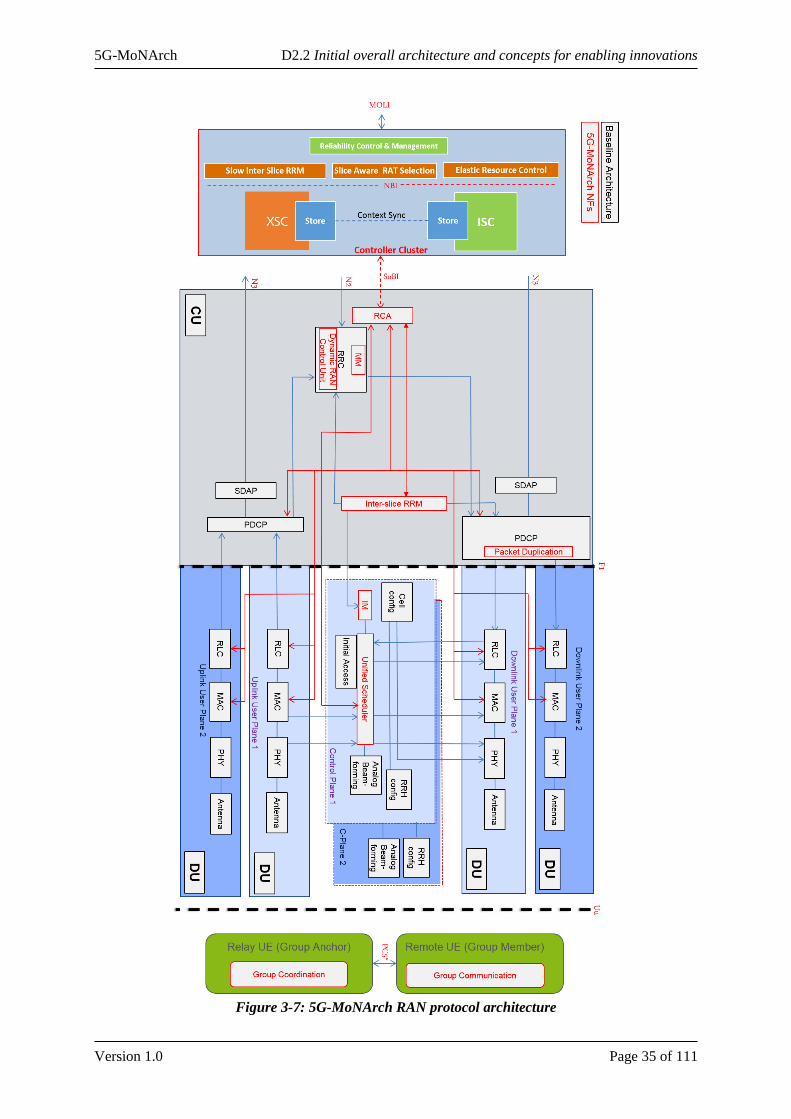
5G-MoNArch D2.2 Initial overall architecture and concepts for enabling innovations
Version 1.0 Page 35 of 111
Figure 3-7: 5G-MoNArch RAN protocol architecture
5G-MoNArch D2.2 Initial overall architecture and concepts for enabling innovations
Version 1.0 Page 36 of 111
3.3.1.1 Slice-aware RRM and RRC
The overall 5G-MoNArch architecture supports the isolation of NSIs, including resource isolation,
OAM isolation, and security isolation. Resource isolation enables specialised customisation and avoids
one slice affecting another slice. E.g. RAN needs to provide and enforce differentiation, and maintain
isolation between slices where resources are constrained including RF resource, backhaul transport
resource and computing resource. Each slice may be assigned with either shared or dedicated radio
resource depending on RRM implementation and SLA. The amount of allocated resources can be scaled
up or down for higher utilisation efficiency depending on the traffic load of each NSI. This section
details Inter-Slice RRM approach followed in 5G-MoNArch to efficiently share and manage Radio
resources between slices.
Inter-slice RRM
The network slice-awareness in 5G RAN will strongly affect the RAN design and particularly the CP
design, where multiple slices, with different optimisation targets, will require tailored access functions
and functional placements to meet their target KPIs. To this end, RRM is one of the key aspects which
will be affected. Here to mention that the operation and placement of RRM will be strongly affected by
the aforementioned slice realisation variants which correspond to the slice isolation at RAN level. In
Slice-aware RAN, in order to offer the flexibility that multiple slices can meet diverse KPIs (e.g., data
rate, latency, and reliability), some RRM functionalities will be required to be tailored for different slice
requirements.
On the other hand, the RAN deployment may provide some limitations on the efficiency of RRM due
to the wireless channel, traffic load, and resource availability constraints, which may affect the overall
performance (assuming numerous slices re-using the same RAN deployment). In particular, in dense
urban heterogeneous scenarios, the signalling and complexity of RRM will be higher due to more
signalling exchanges needed for passing RRM information to different entities. Moreover, the
distribution of RRM functions in different radio nodes will provide new dependencies between RRM
functions, which should be taken care of in order to optimise performance. In addition, in case of HetNet
RAN deployments, non-ideal backhaul between access nodes (macro and small cells) will put some
limitations on the RRM decisions and placement options to meet certain KPIs.
In SotA literature, the distribution of RRM in different nodes is discussed as a way to meet capacity and
coverage demands in dense RANs, where interference management (IM) is critical. There can be
different levels of centralisation of RRM as proposed in literature, namely Centralised, Semi-centralised
and Distributed. For centralised RRM, some solutions have been proposed that require controller for
clusters of HetNets (Cloud-based Resource pooling and management (C-RAN)) [ODK16]. There,
resource pooling and centralised management of resources can provide high gain in terms of capacity.
Nevertheless, this can be realised using ideal backhaul / fronthaul and can be seen as challenging task
for dynamic resource allocation in fast changing environments. Furthermore, other RRM splits are also
discussed in literature, by grouping RRM to real-time and non-real time and distributing them in
different nodes. In [iJOIN D3.3], a flexible C-RAN was proposed where RRM was centralised and in
some scenarios with non-ideal backhaul, real-time RRM could be de-centralised in small cells.
In slice-aware RAN, the CP can be categorised in the following groups of functionalities based on the
RAN Configuration Modes (RCM) framework5. RAN Slice or RAN configuration mode (RCM) has
been proposed in literature; and is a composition of RAN network functions, specific function settings
and associated resources (HW /SW, and network resources). These RCMs will multiplex the traffic
to/from core network slices to ensure optimisation across slices. To ensure meeting the end-to-end slice
requirements, assuming limited RCMs, which may be mapped to numerous slices, a CP functionality
framework is introduced, which is required to allow for slice-tailored optimisation in RAN. In particular:
• Intra-RCM RRM: For slice specific resource management and isolation among slices, utilising
the same RAN is an open topic which is currently investigated. In literature [YT16], the
5 Further details on RCMs have been captured in 5G-MoNArch Deliverable 2.1 [5GM-D2.1].
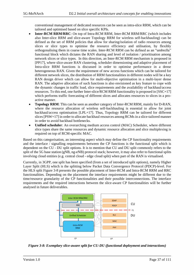
5G-MoNArch D2.2 Initial overall architecture and concepts for enabling innovations
Version 1.0 Page 37 of 111
conventional management of dedicated resources can be seen as intra-slice RRM, which can be
tailored and optimised based on slice specific KPIs.
• Inter-RCM RRM/RRC: On top of Intra-RCM RRM, Inter-RCM RRM/RRC (which includes
also Inter-slice RRM and slice-aware Topology RRM for wireless self-backhauling) can be
defined as the set of RRM policies that allow for sharing/isolation of radio resources among
slices or slice types to optimise the resource efficiency and utilisation, by flexibly
orthogonalising them in coarse time scales. Inter-RCM RRM can be defined as an “umbrella”
functional block which dictates the RAN sharing and level of isolation / prioritisation among
network slices or slice types. In this direction, an Inter-RCM RRM mechanism is proposed in
[PP17], where slice-aware RAN clustering, scheduler dimensioning and adaptive placement of
Intra-slice RRM functions is discussed in order to optimise performance in a dense
heterogeneous RAN. Given the requirement of new access functions which can be tailored for
different network slices, the distribution of RRM functionalities in different nodes will be a key
RAN design driver which can allow for multi-objective optimisation in a multi-layer dense
RAN. The adaptive allocation of such functions is also envisioned as key feature to cope with
the dynamic changes in traffic load, slice requirements and the availability of backhaul/access
resources. To this end, one further Inter-slice/RCM RRM functionality is proposed in [SSC+17]
which performs traffic forecasting of different slices and allocates resources to slices in a pro-
active manner.
• Topology RRM: This can be seen as another category of Inter-RCM RRM, mainly for D-RAN,
where the resource allocation of wireless self-backhauling is essential to allow for joint
backhaul/access optimisation [LPL+17]. Thus, Topology RRM can be tailored for different
slices [PSW+17] in order to allocate backhaul resources among RCMs in a slice-tailored manner
in order to avoid backhaul bottlenecks.
• Unified scheduler: An overarching medium access control (MAC) Scheduler, where different
slice types share the same resources and dynamic resource allocation and slice multiplexing is
required on top of RCM-specific MAC.
Based on this categorisation, an interesting aspect which may define the CP functionality requirements
and the interface / signalling requirements between the CP functions is the functional split which is
dependent on the CU - DU split options. It is to mention that CU and DU split commonly refers to the
split of the 5G base station (gNB, ng-eNB) protocol stack; however, it may also refer to functional splits
involving cloud entities (e.g. central cloud - edge cloud split) when part of the RAN is virtualised.
Currently, in 3GPP, one split has been specified (from a set of introduced split options), namely Higher
Layer Split (HLS) which is the splitting below Packet Data Convergence Protocol (PDCP)-level. For
the HLS split Figure 3-8 presents the possible placement of Inter-RCM and Intra-RCM RRM and RRC
functionalities. Depending on the placement the interface requirements might be different due to the
time/resource granularity of the CP functionalities and their possible interconnections. The interface
requirements and the required interactions between the slice-aware CP functionalities will be further
analysed in future deliverables.
Figure 3-8: Exemplary slice-aware split for CU-DU (functional deployment and interactions)
Intra-RCM RRM
F1
PHY
MAC
RLC
PDCP
CP UP
Inter-RCM RRM/RRC
Unified Scheduler
CU
DU
SDAP
RRC
Exemplary Slice-aware CP Split for CU-DU HLS

5G-MoNArch D2.2 Initial overall architecture and concepts for enabling innovations
Version 1.0 Page 38 of 111
Slow inter-slice RRM based on the Controller layer
The advantages of SDN such as centralised network abstraction and re-programmability can be used as
an alternate solution to implement slice aware RRM. In such approach SDN controller modules along
with centralised RRM function (as NBI application) will be deployed as a VNF on demand managing
radio resources between slices. Slices in turn consist of chained VNFs to implement the E2E network
and can be deployed in the same or physically separated cloud infrastructure. The major objective of
using SDN framework for inter slice RRM is to achieve cross layer optimisation by using various
network parameters such as radio resource status, current data-rate, buffer status, network latency,
priority of slices, etc.
Though the radio resources usage can be better optimised by using centralised and joint optimisation
techniques via SDN framework, there is an inherent latency added due to back and forth communication
between RAN functions and the controller. The centralisation of RRM i.e., to have a radio resource
allocation decision from the controller and send it to the RAN, every scheduling period (~1ms) is almost
impossible due to various communication latencies (e.g., between controller and NB application, NB
application and controller, controller and Scheduler, etc.). So, in order to better realise this centralised
approach, 5G-MoNArch introduced the two-level approach based Inter-slice RRM, i.e., slow Inter-slice
RRM from the controller (>1ms period) and native Inter-slice RRM from the CU (~1ms period).
Slice-aware functional operation
As introduced in D2.1 [5GM-D2.1], slice-aware functional operation can comprise multi-slice resource
management on shared infrastructure resources as well as hard/physical network resources, namely,
wireless access nodes. That is, the slice support may not only include the conventional radio resources
like time and frequency resources, but it can also include the adaptation of the network topology
considering the dynamic small cells (DSCs) available in a certain region. A DSC can comprise access
nodes that are not bound to a fixed topology. For example, relays mounted on vehicles, aka vehicular
nomadic nodes (VNNs), can be considered as DSCs, where VNNs can be activated and deactivated
based on the traffic demand. Further, VNNs may change locations as in case of car sharing or taxi fleet
and may be temporarily available, e.g., during parking time [5GM-D2.1] [BRZ+15]. Slice-aware
functional operation can thus take into account network topology and slice requirements to determine
the functional operation (see Section 4.3.2).
The functional operation can be determined by a dynamic RAN control unit (see Figure 3-7 and Figure
3-9). Depending on the functional operations of the DSCs and how frequently the functional operations
are configured by the RAN control unit, the RAN control unit may reside at different NEs, as
exemplified in Figure 3-9. Two example realisations are provided in the following, while more details
are given in Section 4.3.2.
• In case of L1 functional operation (e.g., physical layer, PHY), L2 functional operation (e.g.,
{PHY, MAC}, or {PHY, MAC, RLC}, or {PHY, MAC, RLC, PDCP}), and amplify-and-
forward modes, the DSC cell is part of the surrounding macro cell and the UE may be connected
both to the DSC and macro cell. Then the configuration of the DSCs can be dynamically or
semi-dynamically changed by a RAN control unit connected to and possibly residing at the RRC
of the macro cell base station (BS)6, as depicted in Figure 3-9 (a). This would necessitate
additional signalling on the self-backhaul (e.g., Un*) interface between macro BS and DSC.
This signalling can configure the reception and transmission modes of the DSC based on the
network slice customer served by the DSC. The dynamicity of such configuration updates
depends on the backhaul link quality and slice requirements. In particular for DSCs like
vehicular nomadic nodes (VNNs) [5GM-D2.1] [BRZ+15], the backhaul link quality will depend
on the position and, thus, at each location change, a new configuration for the functional
operation can be needed. The frequency of such updates can range from minutes to hours.
6 The set-up of the BS may determine the interface that may be impacted. In case of monolithic BS, the impacted
interface would the wireless backhaul interface, while in case of disaggregated BS (i.e., CU-DU split), the impacted
interface would be F1 [3GPP TS38.470].

5G-MoNArch D2.2 Initial overall architecture and concepts for enabling innovations
Version 1.0 Page 39 of 111
Accordingly, having the RAN control unit at the macro cell BS enables more dynamic
functional operation updates in case of dynamic radio topologies.
• In case of L3 functional operation (e.g., {PHY, MAC, RLC, PDCP, SDAP and RRC}), the DSC
may have its own cell, e.g., with a physical cell ID (PCI), and the configuration of the functional
operation may take place at a slow time scale. In this case, as shown in Figure 3-9 (b), in one
implementation, the RAN control unit may have a Cross-slice M&O functionality that resides
at the NSMF. In another implementation, RAN control unit may reside at the RAN, e.g., at
RRC, and may communicate with the Cross-slice M&O functionality for configuring L3 DSC
functional operation, where part of the configuration parameters (such as transmit power) may
be obtained from this Cross-slice M&O functionality.
Figure 3-9: Example Illustration of the slice-aware functional operation with three different modes
(RF-L1, L2, and L3), which are determined and configured by a RAN control unit. Note: Amplify-
and-Forward and Decode-and-Forward are marked as AF and DF, respectively
Slice-aware RAT selection
As already mentioned, the efficient control of the available radio resources and technologies to satisfy
the heterogeneous requirements of different slices is currently an important 5G research challenge. In
the 5G RAN architecture, the 5G-MoNArch concept foresees that in the central unit a mobility
management (MM) module is in charge to optimise the access of the users to a specific RAT, provided
by a 5G distributed unit, according to the slice to which the user is associated. In contrast to classical
association paradigms, this approach will enable to consider slice specific KPIs, like the reliability of
the access technology.
D2D group mobility
Device to Device (D2D) communications facilitates an enabling innovation for further support of service
continuity and smooth mobility (beyond the network edge). This can be realised via offloading some
signalling at the RAN level (from direct signalling to the gNB to indirect signalling between anchor and
remote UEs) as shown in Figure 3-7. As will be detailed in Section 4.1.3, a novel group mobility
paradigm is established with floating mobility anchor as a Group Coordinator, not necessarily “pinned”
to single Relay UEs. The above solution can be confined to RAN domain where the mobility
management is handled by gNB. However, gNB needs to be aware of anchor assignment and associated
remote UEs (i.e., Group Members) per group as will be outlined later.
3.3.1.2 Elastic resource management
Current trends on big data and its pervasiveness open an opportunity to exploit data analytics to improve
the operation of different aspects of the mobile networks by means of data analytics. Although also
previous generation of mobile networks incorporated monitoring data for basic network management,
the extent of the new available data and the heterogeneity of the management decisions that shall be
taken (e.g., radio and cloud resource assignment, per slice) bring this aspect to another level. Moreover,
the increasing availability of machine learning / artificial intelligence algorithms make the data analytics
based network management even more appealing. One of the innovations of 5G-MoNArch is to
incorporate such data analytics into the architecture to improve the operation of certain functions, such
as radio resource optimisation and slice selection. Such data analytics are fed with the data that can be
gathered from the network as a whole (i.e., VNFs and PNFs composing a certain network slice and the
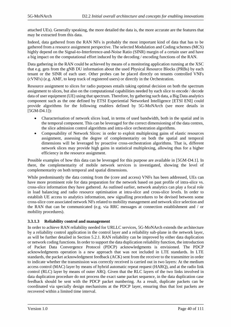
5G-MoNArch D2.2 Initial overall architecture and concepts for enabling innovations
Version 1.0 Page 40 of 111
attached UEs). Generally speaking, the more detailed the data is, the more accurate are the features that
may be extracted from this data.
Indeed, data gathered from the RAN NFs is probably the most important kind of data that has to be
gathered from a resource assignment perspective. The selected Modulation and Coding schemes (MCS)
highly depend on the Signal-to-Interference-and-Noise Ratio (SINR) margin of a certain user and have
a big impact on the computational effort induced by the decoding / encoding functions of the RAN.
Data gathering in the RAN could be achieved by means of a monitoring application running at the XSC
that e.g. gets from the gNB DU information about the used Physical Resource Blocks (PRBs) by each
tenant or the SINR of each user. Other probes can be placed directly on tenants controlled VNFs
(cVNFs) (e.g. AMF, to keep track of registered users) or directly in the Orchestration.
Resource assignment to slices for radio purposes entails taking optimal decision on both the spectrum
assignment to slices, but also on the computational capabilities needed by each slice to encode / decode
data of user equipment (UE) using that spectrum. Therefore, by gathering such data, a Big Data analytics
component such as the one defined by ETSI Experiential Networked Intelligence [ETSI ENI] could
provide algorithms for the following enablers defined by 5G-MoNArch (see more details in
[5GM-D4.1]):
• Characterisation of network slices load, in terms of used bandwidth, both in the spatial and in
the temporal component. This can be leveraged for the correct dimensioning of the data centres,
the slice admission control algorithms and intra-slice orchestration algorithms.
• Composability of Network Slices: in order to exploit multiplexing gains of elastic resources
assignment, assessing the degree of complementarity on both the spatial and temporal
dimensions will be leveraged by proactive cross-orchestration algorithms. That is, different
network slices may provide high gains in statistical multiplexing, allowing thus for a higher
efficiency in the resource assignment.
Possible examples of how this data can be leveraged for this purpose are available in [5GM-D4.1]. In
there, the complementarity of mobile network services is investigated, showing the level of
complementarity on both temporal and spatial dimensions.
While predominantly the data coming from the (core and access) VNFs has been addressed, UEs can
have more prominent role for data preparation for the network based on past profile of intra-slice vs.
cross-slice information they have gathered. As outlined earlier, network analytics can play a focal role
in load balancing and radio resource optimisation at intra-slice and cross-slice levels. In order to
establish UE access to analytics information, new signalling procedures to be devised between some
cross-slice core associated network NFs related to mobility management and network slice selection and
the RAN that can be communicated (e.g. via RRC messages at connection establishment and / or
mobility procedures).
3.3.1.3 Reliability control and management
In order to achieve RAN reliability needed for URLLC services, 5G-MoNArch extends the architecture
by a reliability control application in the control layer and a reliability sub-plane in the network layer,
as will be further detailed in Section 5.2.1. RAN reliability can be improved by either data duplication
or network coding functions. In order to support the data duplication reliability function, the introduction
of Packet Data Convergence Protocol (PDCP) acknowledgments is envisioned. The PDCP
acknowledgments operation is a new approach that was not included in LTE standards. In LTE
standards, the packet acknowledgment feedback (ACK) sent from the receiver to the transmitter in order
to indicate whether the transmission was correctly received is carried out in two layers: At the medium
access control (MAC) layer by means of hybrid automatic repeat request (HARQ), and at the radio link
control (RLC) layer by means of outer ARQ. Given that the RLC layers of the two links involved in
data duplication procedure do not process the exact same packet sequence, in the data duplication case
feedback should be sent with the PDCP packet numbering. As a result, duplicate packets can be
coordinated via specially design mechanisms at the PDCP layer, ensuring thus that lost packets are
recovered within a limited time interval.
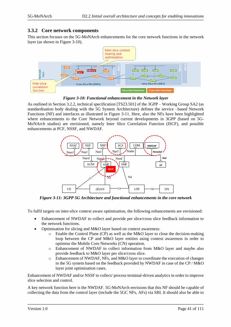
5G-MoNArch D2.2 Initial overall architecture and concepts for enabling innovations
Version 1.0 Page 41 of 111
3.3.2 Core network components
This section focuses on the 5G-MoNArch enhancements for the core network functions in the network
layer (as shown in Figure 3-10).
Figure 3-10: Functional enhancement in the Network layer
As outlined in Section 3.2.2, technical specification [TS23.501] of the 3GPP – Working Group SA2 (as
standardisation body dealing with the 5G System Architecture) defines the service –based Network
Functions (NF) and interfaces as illustrated in Figure 3-11. Here, also the NFs have been highlighted
where enhancements to the Core Network beyond current developments in 3GPP (based on 5G-
MoNArch studies) are envisioned, namely Inter Slice Correlation Function (ISCF), and possible
enhancements at PCF, NSSF, and NWDAF.
Figure 3-11: 3GPP 5G Architecture and functional enhancements in the core network
To fulfil targets on inter-slice context aware optimisation, the following enhancements are envisioned:
• Enhancement of NWDAF to collect and provide per slice/cross slice feedback information to
the network functions.
• Optimisation for slicing and M&O layer based on context awareness:
o Enable the Control Plane (CP) as well as the M&O layer to close the decision-making
loop between the CP and M&O layer entities using context awareness in order to
optimise the Mobile Core Networks (CN) operation.
o Enhancement of NWDAF to collect information from M&O layer and maybe also
provide feedback to M&O layer per slice/cross slice.
o Enhancement of NWDAF, NFs, and M&O layer to coordinate the execution of changes
in the 5G system based on the feedback provided by NWDAF in case of the CP / M&O
layer joint optimisation cases.
Enhancement of NWDAF and/or NSSF to collect/ process terminal-driven analytics in order to improve
slice selection and control.
A key network function here is the NWDAF. 5G-MoNArch envisions that this NF should be capable of
collecting the data from the control layer (include the 5GC NFs, AFs) via SBI. It should also be able to
UE (R)AN UPF
AF
AMF SMF
PCF UDM
DNN6
NRFNEF
N3
N2 N4
AUSF
Nausf Namf Nsmf
NpcfNnrfNnef Nudm Naf
NSSF
Nnssf
AF
NWDAF
Nnwdaf
Naf
ISCF
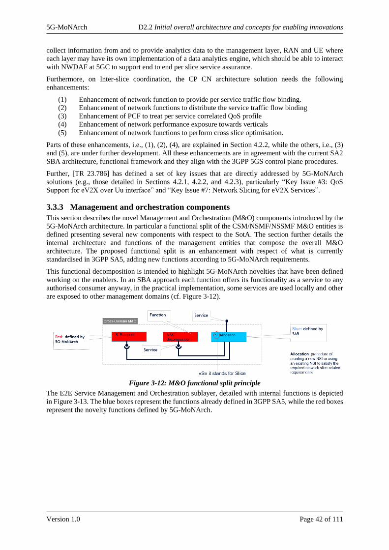
5G-MoNArch D2.2 Initial overall architecture and concepts for enabling innovations
Version 1.0 Page 42 of 111
collect information from and to provide analytics data to the management layer, RAN and UE where
each layer may have its own implementation of a data analytics engine, which should be able to interact
with NWDAF at 5GC to support end to end per slice service assurance.
Furthermore, on Inter-slice coordination, the CP CN architecture solution needs the following
enhancements:
(1) Enhancement of network function to provide per service traffic flow binding.
(2) Enhancement of network functions to distribute the service traffic flow binding
(3) Enhancement of PCF to treat per service correlated QoS profile
(4) Enhancement of network performance exposure towards verticals
(5) Enhancement of network functions to perform cross slice optimisation.
Parts of these enhancements, i.e., (1), (2), (4), are explained in Section 4.2.2, while the others, i.e., (3)
and (5), are under further development. All these enhancements are in agreement with the current SA2
SBA architecture, functional framework and they align with the 3GPP 5GS control plane procedures.
Further, [TR 23.786] has defined a set of key issues that are directly addressed by 5G-MoNArch
solutions (e.g., those detailed in Sections 4.2.1, 4.2.2, and 4.2.3), particularly “Key Issue #3: QoS
Support for eV2X over Uu interface” and “Key Issue #7: Network Slicing for eV2X Services”.
3.3.3 Management and orchestration components
This section describes the novel Management and Orchestration (M&O) components introduced by the
5G-MoNArch architecture. In particular a functional split of the CSM/NSMF/NSSMF M&O entities is
defined presenting several new components with respect to the SotA. The section further details the
internal architecture and functions of the management entities that compose the overall M&O
architecture. The proposed functional split is an enhancement with respect of what is currently
standardised in 3GPP SA5, adding new functions according to 5G-MoNArch requirements.
This functional decomposition is intended to highlight 5G-MoNArch novelties that have been defined
working on the enablers. In an SBA approach each function offers its functionality as a service to any
authorised consumer anyway, in the practical implementation, some services are used locally and other
are exposed to other management domains (cf. Figure 3-12).
Figure 3-12: M&O functional split principle
The E2E Service Management and Orchestration sublayer, detailed with internal functions is depicted
in Figure 3-13. The blue boxes represent the functions already defined in 3GPP SA5, while the red boxes
represent the novelty functions defined by 5G-MoNArch.
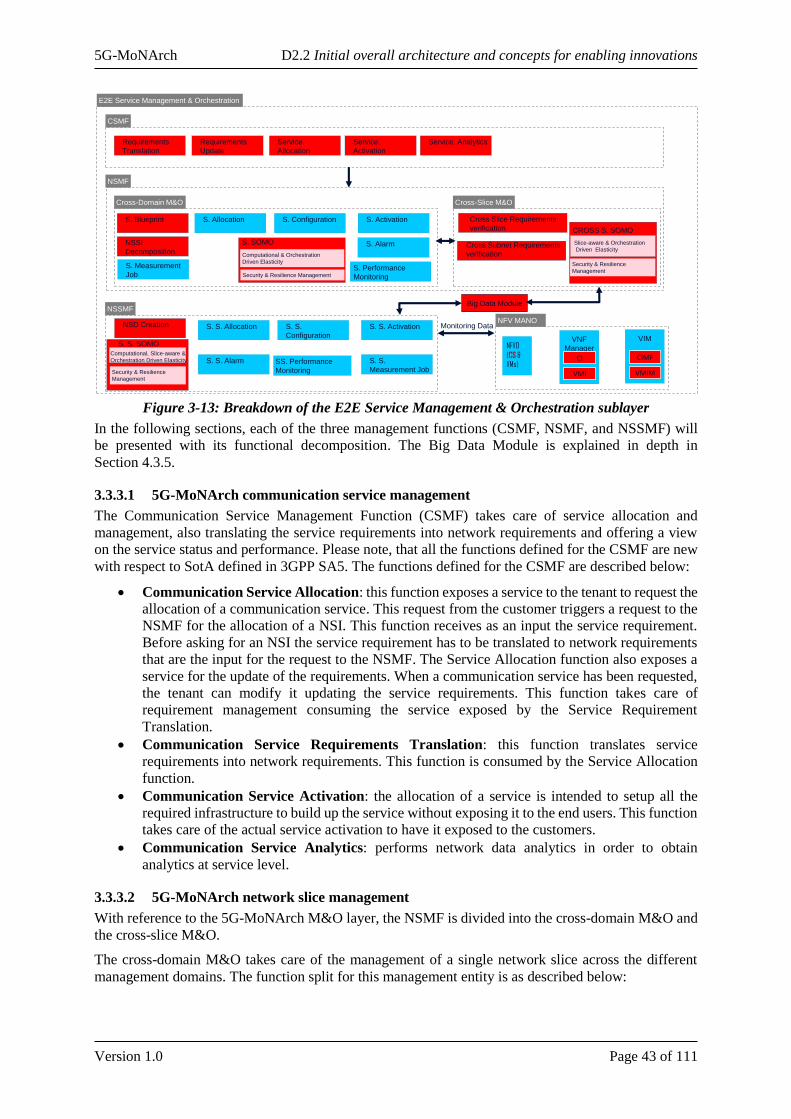
5G-MoNArch D2.2 Initial overall architecture and concepts for enabling innovations
Version 1.0 Page 43 of 111
Figure 3-13: Breakdown of the E2E Service Management & Orchestration sublayer
In the following sections, each of the three management functions (CSMF, NSMF, and NSSMF) will
be presented with its functional decomposition. The Big Data Module is explained in depth in
Section 4.3.5.
3.3.3.1 5G-MoNArch communication service management
The Communication Service Management Function (CSMF) takes care of service allocation and
management, also translating the service requirements into network requirements and offering a view
on the service status and performance. Please note, that all the functions defined for the CSMF are new
with respect to SotA defined in 3GPP SA5. The functions defined for the CSMF are described below:
• Communication Service Allocation: this function exposes a service to the tenant to request the
allocation of a communication service. This request from the customer triggers a request to the
NSMF for the allocation of a NSI. This function receives as an input the service requirement.
Before asking for an NSI the service requirement has to be translated to network requirements
that are the input for the request to the NSMF. The Service Allocation function also exposes a
service for the update of the requirements. When a communication service has been requested,
the tenant can modify it updating the service requirements. This function takes care of
requirement management consuming the service exposed by the Service Requirement
Translation.
• Communication Service Requirements Translation: this function translates service
requirements into network requirements. This function is consumed by the Service Allocation
function.
• Communication Service Activation: the allocation of a service is intended to setup all the
required infrastructure to build up the service without exposing it to the end users. This function
takes care of the actual service activation to have it exposed to the customers.
• Communication Service Analytics: performs network data analytics in order to obtain
analytics at service level.
3.3.3.2 5G-MoNArch network slice management
With reference to the 5G-MoNArch M&O layer, the NSMF is divided into the cross-domain M&O and
the cross-slice M&O.
The cross-domain M&O takes care of the management of a single network slice across the different
management domains. The function split for this management entity is as described below:
E2E Service Management & Orchestration
CSMF
NSMF
Cross-Domain M&O Cross-Slice M&O
NSSMF
S. Allocation S. Configuration S. Activation
S. S. Allocation S. S.
Configuration
S. S. Activation
S. Alarm
S. S. Alarm
Requirements
Translation
Requirements
Update
Service.
Allocation
Service.
Activation
Service. Analytics
S. Blueprint
NSSI
Decomposition
NSD Creation
Cross Slice Requirements
verification
Cross Subnet Requirements
verification
Big Data Module
NFV MANO
NFVO
(CS &
VMs)
VNF
Manager
VMI
CI
VIM
VMIM
CIMF
S. Performance
Monitoring
SS. Performance
Monitoring
Monitoring Data
S. SOMO
Computational & Orchestration
Driven Elasticity
Security & Resilience Management
S. S. SOMO
Computational, Slice-aware &
Orchestration Driven Elasticity
Security & Resilience
Management
CROSS S. SOMO
Slice-aware & Orchestration
Driven Elasticity
Security & Resilience
ManagementS. Measurement
Job
S. S.
Measurement Job
5G-MoNArch D2.2 Initial overall architecture and concepts for enabling innovations
Version 1.0 Page 44 of 111
• Slice Allocation: the slice allocation function takes as an input the network requirements
provided by the CSMF and, also consuming the services exposed by the cross-slice M&O
management entity, reuse an existing NSI or create a new NSI to satisfy the allocation request.
To create a new NSI the network requirements has to be used to create the actual structure of
the NSI in terms of NFs, topology, connectivity and configuration. These data are managed in
the Network Slice Blueprint.
• Slice Blueprint: the function produces the slice constituents/attributes/configuration starting
from the network requirements maybe with the support of predefined templates for specific well
known or standardised slices. The 5G-MoNArch Slice Blueprint, that defines the Network Slice
Instance in terms of network functions, their interconnection and configuration according to a
specific service request, will be presented in Section 0.
• NSSI Decomposition: the function decomposes the network slice into slice subnets producing
the network slice subnet blueprint for each required NSSI
• Slice SOMO (S.SOMO): Self-Organising Management & Orchestration (SOMO) functions
dedicated to the slice life cycle optimisations as well as slice configuration and performance
enhancements, such as resource scaling and NF dynamic deployment, (re-)configuration and
troubleshooting (self-healing). It enables elasticity and the resilience/ security features in the
Management & Orchestration layer.
• Slice Configuration: once the NSI is deployed, this function takes care of the configuration of
slice. As an example, it configures (through the appropriate domains controllers) the
connectivity among the NSSIs.
• Slice Activation: the allocation of a network slice is intended to setup all the required resources
to build up the slice without having it up and running. This function takes care of the actual slice
activation to have it exposed to the customers to support a communication service.
• Slice Alarm: alarms management at slice level, filtering and aggregating the alarms coming
from the different slice subnets to provide alarm information and management for a specific
network slice.
• Slice Performance Monitoring: performance data management at slice level, filtering and
aggregating the performance data coming from the different slice subnets to provide
performance data information and management for a specific network slice.
• Slice Measurement Job: measurement job management at slice level. This function transforms
a request of measurement job for a slice into the appropriate measurement jobs for NSSIs that
compose the NSI.
The cross-slice M&O takes care of the interaction and resource sharing among the deployed NSI. The
function split for this management entity is as described below:
• Cross slice requirements verification: this function supports the allocation of a network slice
evaluating if an existing NSI can also support the new requested communication service in terms
of requirements.
• Cross subnet requirements verification: this function supports the creation of a new network
slice evaluating if existing NSSIs can also support the requirement for the slice subnets that are
constituents of the new network slice.
• Cross Slice SOMO: function dedicated to the Cross-Slice SOMO network algorithms.
The Slice Blueprint, the NSSI decomposition, the S.SOMO and all the functions defined inside the
cross-slice M&O represent new elements with respect to the SotA defined in 3GPP SA5.
3.3.3.3 5G-MoNArch network slice subnet management
The NSSMF manages the network slice subnets that are constituents of a network slice. 5G-MoNArch
architecture foresees multiple NSSMFs e.g. for different domains or technologies. Each NSSMF takes
care of a groups of NFs collected into a management entity name sub network slice that can be shared
among NSIs for resource optimisation.
The functions defined for the network slice subnet are described below:
5G-MoNArch D2.2 Initial overall architecture and concepts for enabling innovations
Version 1.0 Page 45 of 111
• Slice Subnet Allocation: the slice subnet allocation function takes as an input the network slice
subnet requirements provided by the NSMF and, also consuming the services exposed by the
cross-slice M&O management entity, reuse existing NSSIs or create new NSSIs to satisfy the
allocation request.
• Slice Subnet Configuration: once the NSSI is deployed, this function takes of the configuration
of the NSSI. As an example it activates the configuration of the application part of the VNFs
through the network management domain.
• Slice Subnet Activation: the allocation of a network slice subnet is intended to setup all the
required resources to build up the slice subnet without having it up and running. This function
takes care of the actual slice subnet activation to provide the requested network service.
• NSD Creation: creates the Network Service Descriptor for MANO.
• Slice Subnet SOMO (SS.SOMO): function dedicated to the SOMO algorithms for slice
subnets.
• Slice Subnet alarm: alarms management at slice subnet level, filtering and aggregating the
alarms coming from the different NFs to provide alarm information and management for a
specific network slice subnet.
• Slice Subnet Performance Monitoring: performance data management at slice subnet level,
filtering and aggregating the performance data coming from the different NFs to provide
performance data information and management for a specific network slice.
• Slice Subnet Measurement Job: measurement job management at slice subnet level. This
function transforms a request of measurement job for a slice subnet into the appropriate
measurement jobs for the NFs that compose the NSSI.
The NSD Creation and the SS.SOMO functions represent new elements with respect to the SotA defined
in 3GPP SA5.
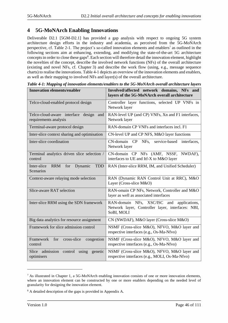
5G-MoNArch D2.2 Initial overall architecture and concepts for enabling innovations
Version 1.0 Page 46 of 111
4 5G-MoNArch Enabling Innovations
Deliverable D2.1 [5GM-D2.1] has provided a gap analysis with respect to ongoing 5G system
architecture design efforts in the industry and academia, as perceived from the 5G-MoNArch
perspective, cf. Table 2-1. The project’s so-called innovation elements and enablers7 as outlined in the
following sections aim at enhancing, extending, and modifying the state-of-the-art 5G architecture
concepts in order to close these gaps8. Each section will therefore detail the innovation element, highlight
the novelties of the concept, describe the involved network functions (NFs) of the overall architecture
(existing and novel NFs, cf. Chapter 3) and describe the work flow (using, e.g., message sequence
charts) to realise the innovations. Table 4-1 depicts an overview of the innovation elements and enablers,
as well as their mapping to involved NFs and layer(s) of the overall architecture.
Table 4-1: Mapping of innovation elements/enablers to the 5G-MoNArch overall architecture layers
Innovation elements/enabler Involved/affected network domains, NFs and
layers of the 5G-MoNArch overall architecture
Telco-cloud-enabled protocol design Controller layer functions, selected UP VNFs in
Network layer
Telco-cloud-aware interface design and
requirements analysis
RAN-level UP (and CP) VNFs, Xn and F1 interfaces,
Network layer
Terminal-aware protocol design RAN-domain CP VNFs and interfaces incl. F1
Inter-slice context sharing and optimisation CN-level UP and CP NFS, M&O layer functions
Inter-slice coordination CN-domain CP NFs, service-based interfaces,
Network layer
Terminal analytics driven slice selection /
control
CN-domain CP NFs (AMF, NSSF, NWDAF),
interfaces to UE and Itf-X to M&O layer
Inter-slice RRM for Dynamic TDD
Scenarios
RAN (Inter-slice RRM, IM, and Unified Scheduler)
Context-aware relaying mode selection RAN (Dynamic RAN Control Unit at RRC), M&O
Layer (Cross-slice M&O)
Slice-aware RAT selection RAN-omain CP NFs, Network, Controller and M&O
layer as well as associated interfaces
Inter-slice RRM using the SDN framework RAN-domain NFs, XSC/ISC and applications,
Network layer, Controller layer, interfaces: NBI,
SoBI, MOLI
Big data analytics for resource assignment CN (NWDAF), M&O layer (Cross-slice M&O)
Framework for slice admission control NSMF (Cross-slice M&O), NFVO, M&O layer and
respective interfaces (e.g., Os-Ma-Nfvo)
Framework for cross-slice congestion
control
NSMF (Cross-slice M&O), NFVO, M&O layer and
respective interfaces (e.g., Os-Ma-Nfvo)
Slice admission control using genetic
optimisers
NSMF (Cross-slice M&O), NFVO, M&O layer and
respective interfaces (e.g., MOLI, Os-Ma-Nfvo)
7 As illustrated in Chapter 1, a 5G-MoNArch enabling innovation consists of one or more innovation elements,
where an innovation element can be constructed by one or more enablers depending on the needed level of
granularity for designing the innovation element.
8 A detailed description of the gaps is provided in Appendix A.

5G-MoNArch D2.2 Initial overall architecture and concepts for enabling innovations
Version 1.0 Page 47 of 111
ML-based optimisation using an extended
FlexRAN implementation
RAN-domain VNFs (CP and UP), Network layer
Computational analysis of open source
mobile network stack implementations
RAN-domain VNFs (CP and UP), Network layer
Measurement campaigns on the
performance of higher layers of the protocol
stack
Higher-layer RAN VNFs (CP and UP), Network layer
The presentation of the innovation elements is structured using the three enabling innovations telco-
cloud-enabled protocol stack (Section 4.1), experiment-driven optimisation (Section 4.5), and inter-
slice control & management, where the latter is split into three sub-groups each representing an
innovation element, namely inter-slice context-aware optimisation (Section 4.2), inter-slice resource
management (Section 4.3), and inter-slice management & orchestration (Section 4.4).
The two enabling innovations telco-cloud-enabled protocol stack and experiment-driven optimisation
have a special role since they do not follow the classical approach of designing a network function for
a specific purpose, e.g., optimisation of resource utilisation. Rather, they propose a completely new
approach to system architecture design. While the former focuses on minimising cross-functional
dependencies (e.g., telco-cloud-ready function and interface designs in the RAN), the latter uses
observations and results from operational networks to enhance the architecture and the behaviour
individual NFs (e.g., resource orchestration algorithms used in the M&O layer). Therefore, these
innovations do not always have an immediate representation in the functional architecture.
Telco-cloud-enabled protocol stack
The expected advantages brought by a cloud-enabled protocol stack design are backed by the relative
maturity of current software initiatives (such as, Open Air Interface [OAI] or SRS LTE [SRSLTE]) and
the recent increase in the pace of their updates. Moreover, this also provides the motivation and the
means for researchers to investigate possible enhancements of technologies that have only been
available in rather proprietary manner in the past, such as, cellular radio protocol implementations.
In future, fully softwarised and cloudified mobile networks will necessarily build on cloud-aware
protocol stacks. Both network management and the resulting overall performance will benefit from
making VNFs aware of being executed on shared resources by means of virtualisation environments
such as virtual machines or containers. In this section, the main challenges to achieve this vision are
discussed, while and describing possible implementations of functionality that builds on this cloud-
awareness.
This approach entails two main challenges, namely (i) redefining the interactions between VNFs,
relaxing as much as possible their temporal and logical connections, and (ii) support an elastic operation,
to efficiently cope with changing input loads while running in an infrastructure of resources that is not
over-provisioned. The functional requirements of these novel design strategies are detailed in what
follows, before discussing why they will also require the formal definition of novel Key Performance
Indicators, cf. [5GM-D6.1].
Given the high flexibility provided by the NFV approach, the deployment of such cloud-aware protocol
stack does not have a direct negative implication on the provided telecommunication service per se. The
re-definition of the interactions among VNFs allows for a more flexible service orchestration, while the
re-design of VNF internals may be easily provided by a code refactoring in a much faster way than the
current tightly coupled HW-SW PNF approach. While having a cloud-aware protocol stack will benefit
any kind of telecommunication service, this may be particularly relevant for the extreme ones. For
example, a mission critical VNF can be optimised to reduce its memory footprint, while low latency
services may exploit especially tailored orchestration patterns involving edge computing facilities.

5G-MoNArch D2.2 Initial overall architecture and concepts for enabling innovations
Version 1.0 Page 48 of 111
4.1.1 Telco-cloud-aware protocol design
Concept
Future network architectures will heavily rely on the flexible function decomposition and allocation.
That is, the former monolithic PNF are split into interconnected modules that can be concatenated to
provide the same functionality: e.g., a physical eNodeB is split into PHY, MAC, RLC and PDCP SW
implementations running in different execution containers, which can be located in different nodes of
the cloudified network.
This approach provides several advantages, as it allows heterogeneous deployments for different
services (i.e., mMTC, eMBB), which are tailored to their specific requirements. For example, depending
on the latency, bandwidth, and/or computational requirements of the service, it may be better to locate
certain VNF towards the edge of the cloud rather than in a central location. How to place VNF across
the cloud is a network orchestration problem, which is constrained by the split into modules described
above. However, this typical NF decomposition for the RAN protocol stack was not designed for its
cloudification, and therefore the potential gains are limited. This issue is discussed in more detail in the
following. Also, the deployment of VNF in computational resources constrained environments, such as
edge clouds, takes advantage of this enabler.
One key assumption of network stack designs is that certain functions are implemented in the same
physical space, e.g., within the same chip. (maybe on a different chip, but surely on the same HW). So,
non-ideal links with non-negligible delays are a problem for physical network elements that need to be
decomposed into several network functions. Interfaces among them, thus, were designed considering
communication links spanning some microns of silicon, and not several miles of fibre as in the case of,
e.g., C-RAN.
In this way, the possible inter-dependencies between these functions are overlooked, as the delivery of
information between them is practically immediate. However, as argued above, to fully benefit from a
network-wide orchestration of a cloudified stack, VNF should support their execution on different
nodes. But the design of traditional protocol stacks does not support such flexible placement of VNF, as
those with heavy inter-dependencies may introduce very high coordination overheads, or may not be
even possible due to infeasible network requirements. These limitations severely constrain network
orchestration, which compromises the overall gains obtained from the flexible function allocation. This
is flagrant for e.g., the introduction of centralised RAN functions, where long delays in the information
exchange between radio access points and the central cloud result in serious performance deterioration.
Position in 5G-MoNArch architecture
Because of the above, the full protocol stack (and, in particular, the RAN) has to be re-designed with
the goal of leveraging the benefits of the flexible function decomposition and allocation, so as to cope
with non-ideal communication (i.e., non-zero and varying delay, limited throughput) between the nodes
in the cloud. Specifically, a cloud-aware protocol stack should relax as much as possible, or even
completely remove, the logical and temporal dependencies between VNF, such as very tight timing
constraints for the HARQ, to enable their parallel execution and provide a higher flexibility in their
placement.
One of the most immediate and appealing advantages of a cloudified network is the possibility of
reducing costs, by adapting and re-distributing resources following (and even anticipating) temporal and
spatial traffic variations. However, it is also likely that in certain occasions the resource assignment
across the cloud cannot cope with the existing traffic due to some peaks of resource demands. This is
particularly true for C-RAN deployments, that have to deal with demand loads known to be highly
variable. In this scenario, allocating resources based on peak requirements would be highly inefficient,
as this design jeopardises multiplexing gains in particular when cloud resources may be scarce (e.g., a
"flash crowd" at an edge cloud): here any temporal shortage might result in a heavy congestion or even
a system failure. VNF, instead, shall efficiently use the resources they are assigned with. Thus, they
have to become elastic, i.e., adapt their operation when temporal changes in the resources available
occur, in the same way they have a long-established manner of dealing with outages such e.g. channel
errors. Therefore, to fully exploit the benefits of softwarising the network operation, the NF design has
to take the potential scarcity into account and be prepared to react accordingly.

5G-MoNArch D2.2 Initial overall architecture and concepts for enabling innovations
Version 1.0 Page 49 of 111
This enabler does not have a direct implication on the 5G-MoNArch architecture per-se, but it will
provide the fundamental building blocks (i.e., cVNFs and uVNFs) on the network layer, that will be
used by the controllers and M&O to achieve elasticity or resilience.
Evaluation and analyses
In the context of wireless communications, the concept of elasticity usually refers to a graceful
performance degradation when the spectrum becomes insufficient to serve all users. However, in the
framework of a cloudified operation of mobile networks that has to deal with elasticity under resource
shortages, also other kinds of resources need to be considered that are native to the cloud environment
such as computational, memory, and storage assets available to the containers the VNF are bound to.
This has hardly been a problem for traditional NFs, that were designed to run over a given HW substrate
with exclusive access to the resources and requires the definition of novel interfaces that will provide
the amount and type of available cloud resources at a given point in time, just like, e.g., the accessible
spectrum is a parameter for a RAN function.
Elasticity has also been considered by non-VNF cloud operators, but the presented concept deviates
very much from theirs: the time scales involved in RAN functions are significantly more stringent than
the ones required by, e.g., a Big Data platform or a web server back-end. Another key difference is that
resources are way more scattered in the presented scenario (e.g. they are distributed across the "edge
clouds"), which reduces the possibility of damping peaks by aggregating resources.
Figure 4-1: Telco-cloud-aware (elastic) VNF operation (illustrative)
To better illustrate the benefits of elasticity in the cloudified mobile network operation context, firstly
the notion of “computational outage” is considered, i.e., the unavailability of the required resources to
perform the expected operation. In a traditional, non-elastic operation, there is a 1-to-1 mapping between
outages and performance loss, as Figure 4-1illustrates: if the resources are not available 20\% of the
time, there is a 20% performance degradation, as the function is unable to operate under any shortage.
In contrast, an elastic design supports what hereafter is referred to as graceful performance degradation,
which causes that the VNF would still work under a resource shortage (with reduced performance,
though), this resulting in the "gains" qualitatively illustrated in the Figure 4-1. Making a protocol stack
cloud-aware through elastic VNF requires hence a paradigm shift in their design, moving away from the
tight HW-SW co-design as discussed before, to a flexible operation in which the amount of available
resources is an additional parameter.
To fully take advantage of elastic VNF, a detailed analysis of their operation is required: first, a thorough
assessment of the resources consumed during execution, including statistics about temporal variations
over time; second, a characterisation of the correlations between VNF operations, to serve as input for
the orchestration algorithm, so it could e.g. dynamically assign resources to resilient VNFs and quickly
"rescue" them when outages happen. Indeed, the quest for cloudification will end up with novel
orchestration algorithms. Specific algorithms are defined in WP4, but the overall operation can be
generalised as depicted in Figure 4-2.
0 25 50 75 100
Computational Outage probability [%]
0
25
50
75
100
Perf
orm
ance
[%] Elasticity Gains
Min
imum
Fo
otp
rin
t
Elastic Approach
Traditional Approach

5G-MoNArch D2.2 Initial overall architecture and concepts for enabling innovations
Version 1.0 Page 50 of 111
Figure 4-2: Telco-cloud-aware protocol stack operation for elasticity
4.1.2 Telco-cloud-aware interface design and requirements analysis
Concept
Besides the novel design of elastic VNFs, one of the most challenging tasks to introduce a cloud-enabled
RAN protocol stack is to derive requirements regarding the interface among VNFs which include
separated RAN functionalities such as the MAC scheduler, or PHY layer procedures. It is also for further
study to what extent the RAN protocol stack can be cloudified. Especially in the MAC and PHY layer
delay requirements and interdependencies among functions are critical.
A first study related to these targets and challenges is presented in [5GM-D4.1]. The basic architecture
to introduce a cloud enabled protocol stack is illustrated in Figure 4-3. On the one hand, an extension to
3GPP’s Xn and F1 interfaces to provide much higher flexibility is required as well as extensions
regarding the transport protocol to interconnect multiple, e.g., containers among multiple physical
machines is needed. The yellow boxes represent the virtualised environment of the either CP or UP
functionality illustrated as blue boxes. One of the major upcoming tasks is to derive subgroups of
functionalities dependent on the limitations defined by acceptable additional delay and
interdependencies of functionalities which then will be virtualised.
Position in 5G-MoNArch architecture
Telco-cloud-aware interface design affects the 5G-MoNArch RAN functions and interfaces. It mainly
analyses UP functions, but also potential interdependencies of CP sub-functions are covered. Moreover,
the proposed concept affects the interfaces Xn and F1 as defined by 3GPP for Release 15. In the 5G-
MoNArch context, both interfaces reside in the Network layer.
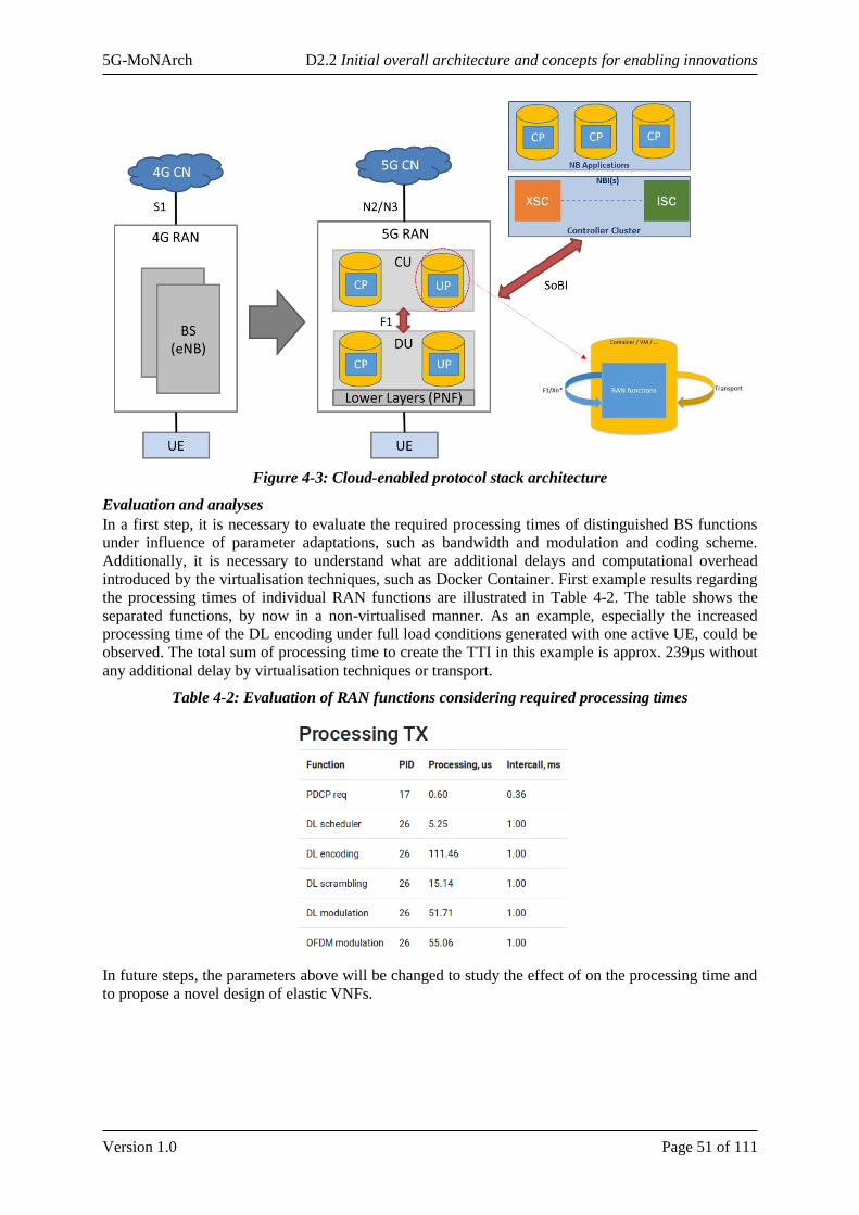
5G-MoNArch D2.2 Initial overall architecture and concepts for enabling innovations
Version 1.0 Page 51 of 111
Figure 4-3: Cloud-enabled protocol stack architecture
Evaluation and analyses
In a first step, it is necessary to evaluate the required processing times of distinguished BS functions
under influence of parameter adaptations, such as bandwidth and modulation and coding scheme.
Additionally, it is necessary to understand what are additional delays and computational overhead
introduced by the virtualisation techniques, such as Docker Container. First example results regarding
the processing times of individual RAN functions are illustrated in Table 4-2. The table shows the
separated functions, by now in a non-virtualised manner. As an example, especially the increased
processing time of the DL encoding under full load conditions generated with one active UE, could be
observed. The total sum of processing time to create the TTI in this example is approx. 239µs without
any additional delay by virtualisation techniques or transport.
Table 4-2: Evaluation of RAN functions considering required processing times
In future steps, the parameters above will be changed to study the effect of on the processing time and
to propose a novel design of elastic VNFs.
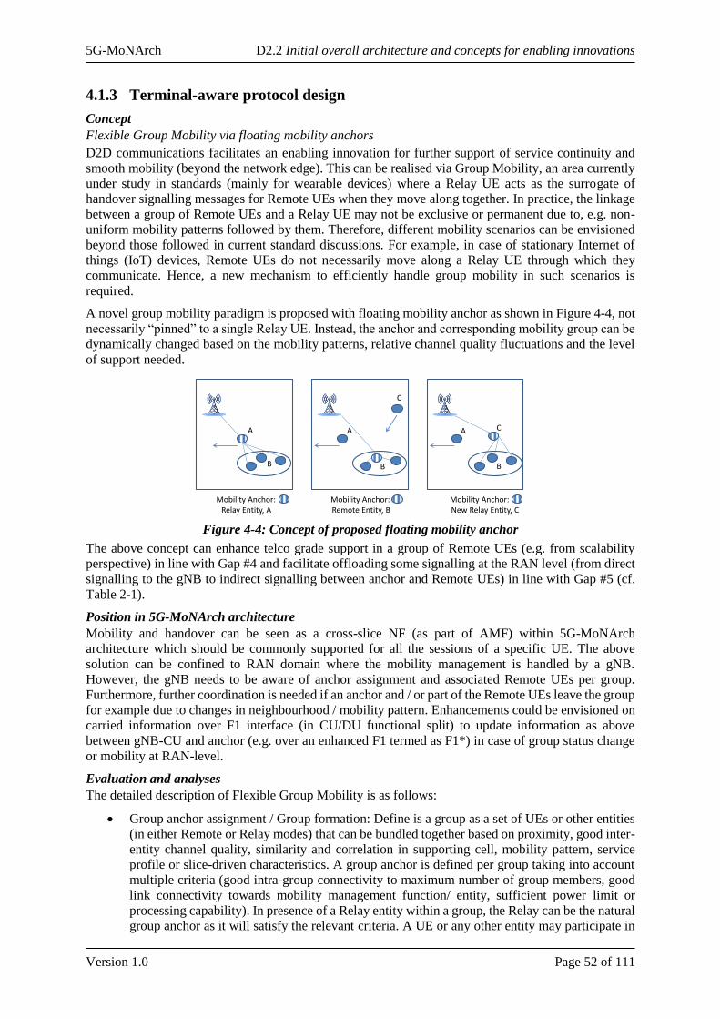
5G-MoNArch D2.2 Initial overall architecture and concepts for enabling innovations
Version 1.0 Page 52 of 111
4.1.3 Terminal-aware protocol design
Concept
Flexible Group Mobility via floating mobility anchors
D2D communications facilitates an enabling innovation for further support of service continuity and
smooth mobility (beyond the network edge). This can be realised via Group Mobility, an area currently
under study in standards (mainly for wearable devices) where a Relay UE acts as the surrogate of
handover signalling messages for Remote UEs when they move along together. In practice, the linkage
between a group of Remote UEs and a Relay UE may not be exclusive or permanent due to, e.g. non-
uniform mobility patterns followed by them. Therefore, different mobility scenarios can be envisioned
beyond those followed in current standard discussions. For example, in case of stationary Internet of
things (IoT) devices, Remote UEs do not necessarily move along a Relay UE through which they
communicate. Hence, a new mechanism to efficiently handle group mobility in such scenarios is
required.
A novel group mobility paradigm is proposed with floating mobility anchor as shown in Figure 4-4, not
necessarily “pinned” to a single Relay UE. Instead, the anchor and corresponding mobility group can be
dynamically changed based on the mobility patterns, relative channel quality fluctuations and the level
of support needed.
Figure 4-4: Concept of proposed floating mobility anchor
The above concept can enhance telco grade support in a group of Remote UEs (e.g. from scalability
perspective) in line with Gap #4 and facilitate offloading some signalling at the RAN level (from direct
signalling to the gNB to indirect signalling between anchor and Remote UEs) in line with Gap #5 (cf.
Table 2-1).
Position in 5G-MoNArch architecture
Mobility and handover can be seen as a cross-slice NF (as part of AMF) within 5G-MoNArch
architecture which should be commonly supported for all the sessions of a specific UE. The above
solution can be confined to RAN domain where the mobility management is handled by a gNB.
However, the gNB needs to be aware of anchor assignment and associated Remote UEs per group.
Furthermore, further coordination is needed if an anchor and / or part of the Remote UEs leave the group
for example due to changes in neighbourhood / mobility pattern. Enhancements could be envisioned on
carried information over F1 interface (in CU/DU functional split) to update information as above
between gNB-CU and anchor (e.g. over an enhanced F1 termed as F1*) in case of group status change
or mobility at RAN-level.
Evaluation and analyses
The detailed description of Flexible Group Mobility is as follows:
• Group anchor assignment / Group formation: Define is a group as a set of UEs or other entities
(in either Remote or Relay modes) that can be bundled together based on proximity, good inter-
entity channel quality, similarity and correlation in supporting cell, mobility pattern, service
profile or slice-driven characteristics. A group anchor is defined per group taking into account
multiple criteria (good intra-group connectivity to maximum number of group members, good
link connectivity towards mobility management function/ entity, sufficient power limit or
processing capability). In presence of a Relay entity within a group, the Relay can be the natural
group anchor as it will satisfy the relevant criteria. A UE or any other entity may participate in
Mobility Anchor:Relay Entity, A
Mobility Anchor:Remote Entity, B
Mobility Anchor:New Relay Entity, C
A A
C
CA
B B B

5G-MoNArch D2.2 Initial overall architecture and concepts for enabling innovations
Version 1.0 Page 53 of 111
multiple groups assuming multiple-service/ slice profiles. As a result, a Remote entity in one
group can be a Relay entity in another group. The exclusivity or generality of the groups is
subject to network operator’s decision. A group anchor aggregates individual group member
signalling messages related to mobility management (anchor change or handover) towards/ from
a gNB or relevant gNB-CU based on the level of support needed.
• User Update: should a group member leave the group, the gNB-CU and the group anchor send
an updated list of associated Remote UEs to each other to coordinate on the changes.
• Anchor change: If the current group anchor leaves the group (e.g. due to changes in mobility
pattern, channel quality or service/slice profile), a reassignment procedure is triggered so a new
group anchor is designated by the network (gNB-CU) and the old anchor is released. Therefore,
the anchor role can dynamically float across candidate members.
• Group handover: If a handover procedure is triggered via group anchor (e.g. due to the changes
of channel quality to the gNB), the gNB or relevant gNB-CU decides on remote UEs to be
shifted to another anchor (via anchor change procedure) or alternatively Remote UEs to be
handed over (along the old anchor) to another gNB. The anchor change or handover of Remote
UEs should precede any old anchor handover. Afterwards, the old anchor handover can be
followed.
Figure 4-5 shows the Message Sequence Chart for the proposed concept for different stages, in particular
for anchor change and group handover as described above.
Figure 4-5: Message sequence chart of the anchor change / group handover concept
Inter-slice context-aware optimisation
4.2.1 Inter-slice context sharing and optimisation
Concept
5G Systems Phase 1 (i.e., Release 15) defines NWDA function in the network layer to perform per slice
data analytics for service assurance. While cross slice context sharing and E2E cross-slice optimisation
is not fully supported. This work focuses on defining entities in a mobile network that can operate with
context awareness to close the loop of decision-making between entities of the Network layer and M&O
layer in order to optimise intra and inter network slice operations. The work covers the following
aspects:
Remote UE Anchor DU CU
F1*
F1PC5
Anchor assignment
Any user update?
Anchor status change
New Anchor assignment
Group formation
Any user update?
Associated remote UEs
update
Anchor HO request
Remote UE HO
Old Anchor release
Anchor HO
Uu
Group anchor assignment
User update
Anchor change
Group HO
Group formation
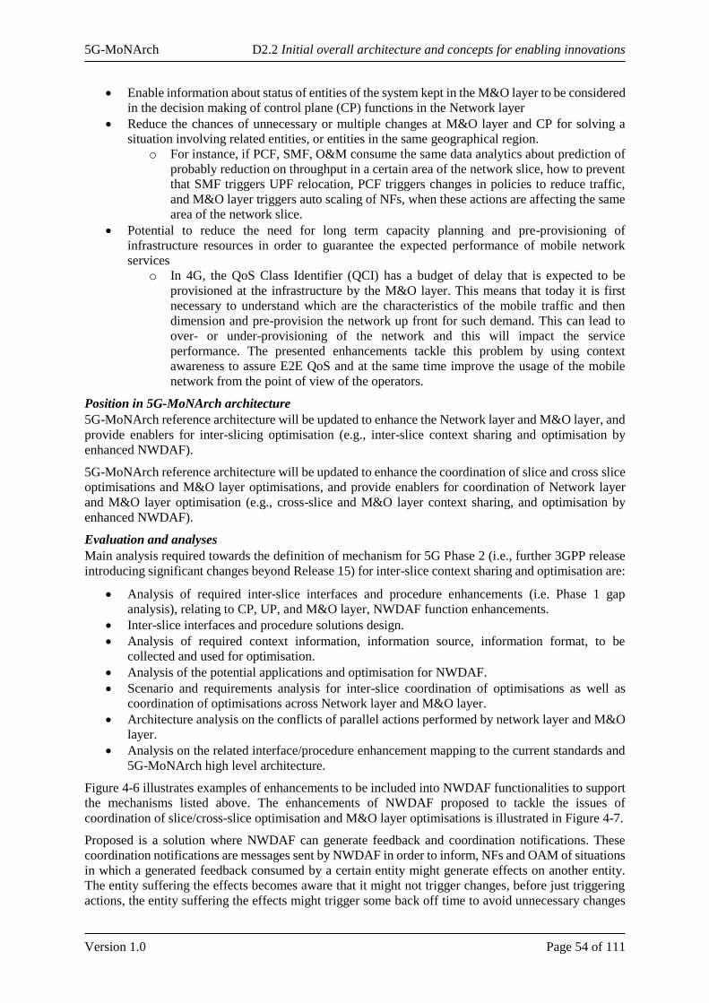
5G-MoNArch D2.2 Initial overall architecture and concepts for enabling innovations
Version 1.0 Page 54 of 111
• Enable information about status of entities of the system kept in the M&O layer to be considered
in the decision making of control plane (CP) functions in the Network layer
• Reduce the chances of unnecessary or multiple changes at M&O layer and CP for solving a
situation involving related entities, or entities in the same geographical region.
o For instance, if PCF, SMF, O&M consume the same data analytics about prediction of
probably reduction on throughput in a certain area of the network slice, how to prevent
that SMF triggers UPF relocation, PCF triggers changes in policies to reduce traffic,
and M&O layer triggers auto scaling of NFs, when these actions are affecting the same
area of the network slice.
• Potential to reduce the need for long term capacity planning and pre-provisioning of
infrastructure resources in order to guarantee the expected performance of mobile network
services
o In 4G, the QoS Class Identifier (QCI) has a budget of delay that is expected to be
provisioned at the infrastructure by the M&O layer. This means that today it is first
necessary to understand which are the characteristics of the mobile traffic and then
dimension and pre-provision the network up front for such demand. This can lead to
over- or under-provisioning of the network and this will impact the service
performance. The presented enhancements tackle this problem by using context
awareness to assure E2E QoS and at the same time improve the usage of the mobile
network from the point of view of the operators.
Position in 5G-MoNArch architecture
5G-MoNArch reference architecture will be updated to enhance the Network layer and M&O layer, and
provide enablers for inter-slicing optimisation (e.g., inter-slice context sharing and optimisation by
enhanced NWDAF).
5G-MoNArch reference architecture will be updated to enhance the coordination of slice and cross slice
optimisations and M&O layer optimisations, and provide enablers for coordination of Network layer
and M&O layer optimisation (e.g., cross-slice and M&O layer context sharing, and optimisation by
enhanced NWDAF).
Evaluation and analyses
Main analysis required towards the definition of mechanism for 5G Phase 2 (i.e., further 3GPP release
introducing significant changes beyond Release 15) for inter-slice context sharing and optimisation are:
• Analysis of required inter-slice interfaces and procedure enhancements (i.e. Phase 1 gap
analysis), relating to CP, UP, and M&O layer, NWDAF function enhancements.
• Inter-slice interfaces and procedure solutions design.
• Analysis of required context information, information source, information format, to be
collected and used for optimisation.
• Analysis of the potential applications and optimisation for NWDAF.
• Scenario and requirements analysis for inter-slice coordination of optimisations as well as
coordination of optimisations across Network layer and M&O layer.
• Architecture analysis on the conflicts of parallel actions performed by network layer and M&O
layer.
• Analysis on the related interface/procedure enhancement mapping to the current standards and
5G-MoNArch high level architecture.
Figure 4-6 illustrates examples of enhancements to be included into NWDAF functionalities to support
the mechanisms listed above. The enhancements of NWDAF proposed to tackle the issues of
coordination of slice/cross-slice optimisation and M&O layer optimisations is illustrated in Figure 4-7.
Proposed is a solution where NWDAF can generate feedback and coordination notifications. These
coordination notifications are messages sent by NWDAF in order to inform, NFs and OAM of situations
in which a generated feedback consumed by a certain entity might generate effects on another entity.
The entity suffering the effects becomes aware that it might not trigger changes, before just triggering
actions, the entity suffering the effects might trigger some back off time to avoid unnecessary changes
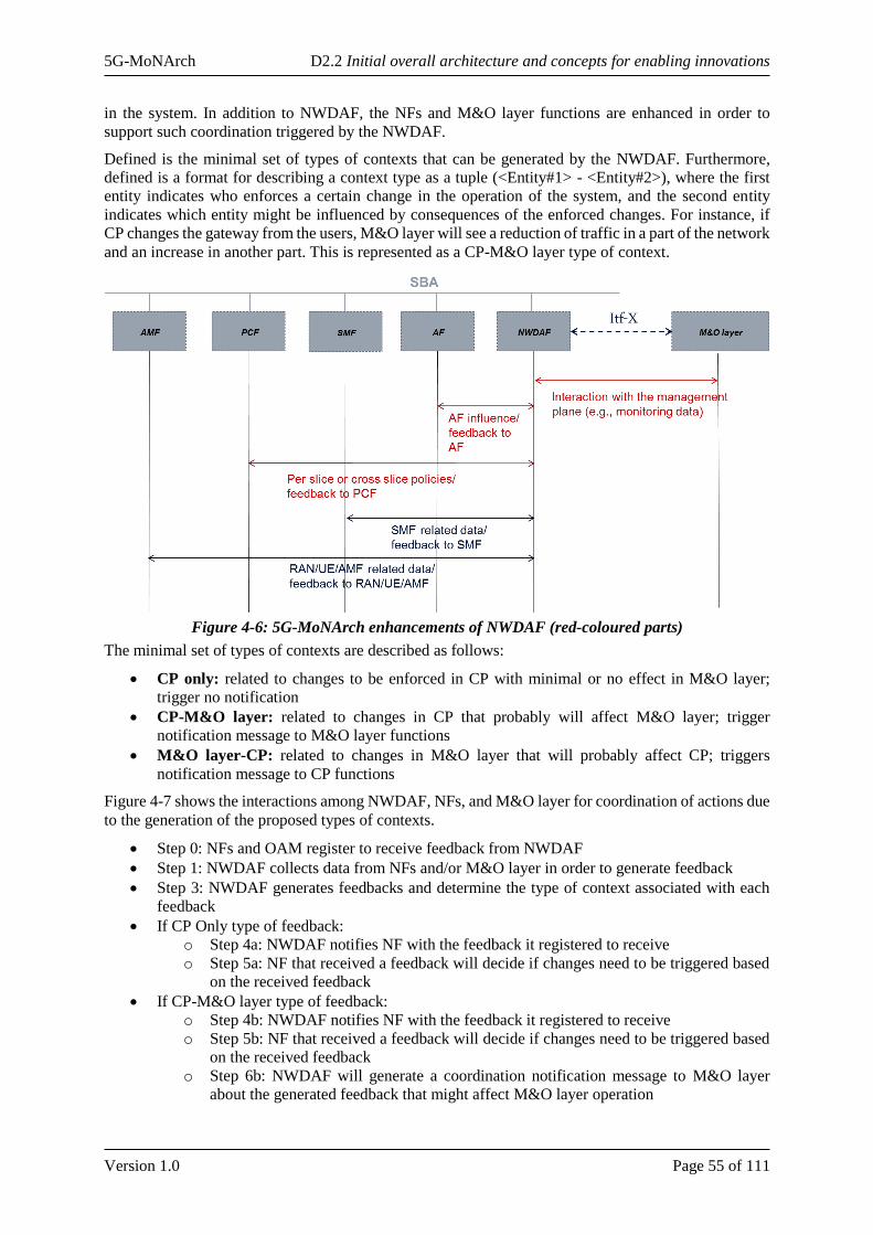
5G-MoNArch D2.2 Initial overall architecture and concepts for enabling innovations
Version 1.0 Page 55 of 111
in the system. In addition to NWDAF, the NFs and M&O layer functions are enhanced in order to
support such coordination triggered by the NWDAF.
Defined is the minimal set of types of contexts that can be generated by the NWDAF. Furthermore,
defined is a format for describing a context type as a tuple (<Entity#1> - <Entity#2>), where the first
entity indicates who enforces a certain change in the operation of the system, and the second entity
indicates which entity might be influenced by consequences of the enforced changes. For instance, if
CP changes the gateway from the users, M&O layer will see a reduction of traffic in a part of the network
and an increase in another part. This is represented as a CP-M&O layer type of context.
Figure 4-6: 5G-MoNArch enhancements of NWDAF (red-coloured parts)
The minimal set of types of contexts are described as follows:
• CP only: related to changes to be enforced in CP with minimal or no effect in M&O layer;
trigger no notification
• CP-M&O layer: related to changes in CP that probably will affect M&O layer; trigger
notification message to M&O layer functions
• M&O layer-CP: related to changes in M&O layer that will probably affect CP; triggers
notification message to CP functions
Figure 4-7 shows the interactions among NWDAF, NFs, and M&O layer for coordination of actions due
to the generation of the proposed types of contexts.
• Step 0: NFs and OAM register to receive feedback from NWDAF
• Step 1: NWDAF collects data from NFs and/or M&O layer in order to generate feedback
• Step 3: NWDAF generates feedbacks and determine the type of context associated with each
feedback
• If CP Only type of feedback:
o Step 4a: NWDAF notifies NF with the feedback it registered to receive
o Step 5a: NF that received a feedback will decide if changes need to be triggered based
on the received feedback
• If CP-M&O layer type of feedback:
o Step 4b: NWDAF notifies NF with the feedback it registered to receive
o Step 5b: NF that received a feedback will decide if changes need to be triggered based
on the received feedback
o Step 6b: NWDAF will generate a coordination notification message to M&O layer
about the generated feedback that might affect M&O layer operation
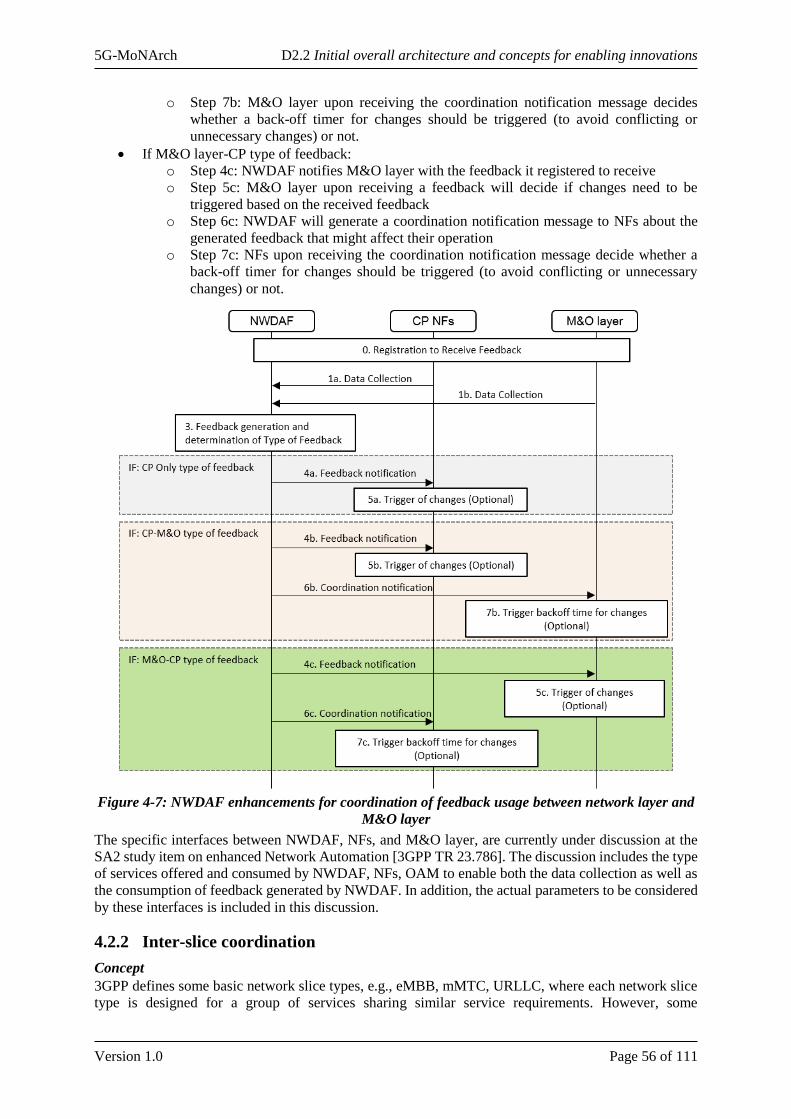
5G-MoNArch D2.2 Initial overall architecture and concepts for enabling innovations
Version 1.0 Page 56 of 111
o Step 7b: M&O layer upon receiving the coordination notification message decides
whether a back-off timer for changes should be triggered (to avoid conflicting or
unnecessary changes) or not.
• If M&O layer-CP type of feedback:
o Step 4c: NWDAF notifies M&O layer with the feedback it registered to receive
o Step 5c: M&O layer upon receiving a feedback will decide if changes need to be
triggered based on the received feedback
o Step 6c: NWDAF will generate a coordination notification message to NFs about the
generated feedback that might affect their operation
o Step 7c: NFs upon receiving the coordination notification message decide whether a
back-off timer for changes should be triggered (to avoid conflicting or unnecessary
changes) or not.
Figure 4-7: NWDAF enhancements for coordination of feedback usage between network layer and
M&O layer
The specific interfaces between NWDAF, NFs, and M&O layer, are currently under discussion at the
SA2 study item on enhanced Network Automation [3GPP TR 23.786]. The discussion includes the type
of services offered and consumed by NWDAF, NFs, OAM to enable both the data collection as well as
the consumption of feedback generated by NWDAF. In addition, the actual parameters to be considered
by these interfaces is included in this discussion.
4.2.2 Inter-slice coordination
Concept
3GPP defines some basic network slice types, e.g., eMBB, mMTC, URLLC, where each network slice
type is designed for a group of services sharing similar service requirements. However, some
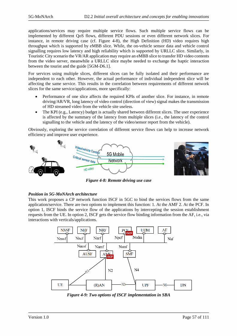
5G-MoNArch D2.2 Initial overall architecture and concepts for enabling innovations
Version 1.0 Page 57 of 111
applications/services may require multiple service flows. Such multiple service flows can be
implemented by different QoS flows, different PDU sessions or even different network slices. For
instance, in remote driving case (cf. Figure 4-8), the High Definition (HD) video requires high
throughput which is supported by eMBB slice. While, the on-vehicle sensor data and vehicle control
signalling requires low latency and high reliability which is supported by URLLC slice. Similarly, in
Touristic City scenario the VR/AR application may require an eMBB slice to transfer HD video contents
from the video server, meanwhile a URLLC slice maybe needed to exchange the haptic interaction
between the tourist and the guide [5GM-D6.1].
For services using multiple slices, different slices can be fully isolated and their performance are
independent to each other. However, the actual performance of individual independent slice will be
affecting the same service. This results in the correlation between requirements of different network
slices for the same service/applications, more specifically:
• Performance of one slice affects the required KPIs of another slice. For instance, in remote
driving/AR/VR, long latency of video control (direction of view) signal makes the transmission
of HD streamed video from the vehicle site useless.
• The KPI (e.g., Latency) budget is actually shared between different slices. The user experience
is affected by the summary of the latency from multiple slices (i.e., the latency of the control
signalling to the vehicle and the latency of the video/sensor report from the vehicle).
Obviously, exploring the service correlation of different service flows can help to increase network
efficiency and improve user experience.
Figure 4-8: Remote driving use case
Position in 5G-MoNArch architecture
This work proposes a CP network function ISCF in 5GC to bind the services flows from the same
application/service. There are two options to implement this function: 1. At the AMF 2. At the PCF. In
option 1, ISCF binds the service flow of the applications by intercepting the session establishment
requests from the UE. In option 2, ISCF gets the service flow binding information from the AF, i.e., via
interactions with verticals/applications.
Figure 4-9: Two options of ISCF implementation in SBA
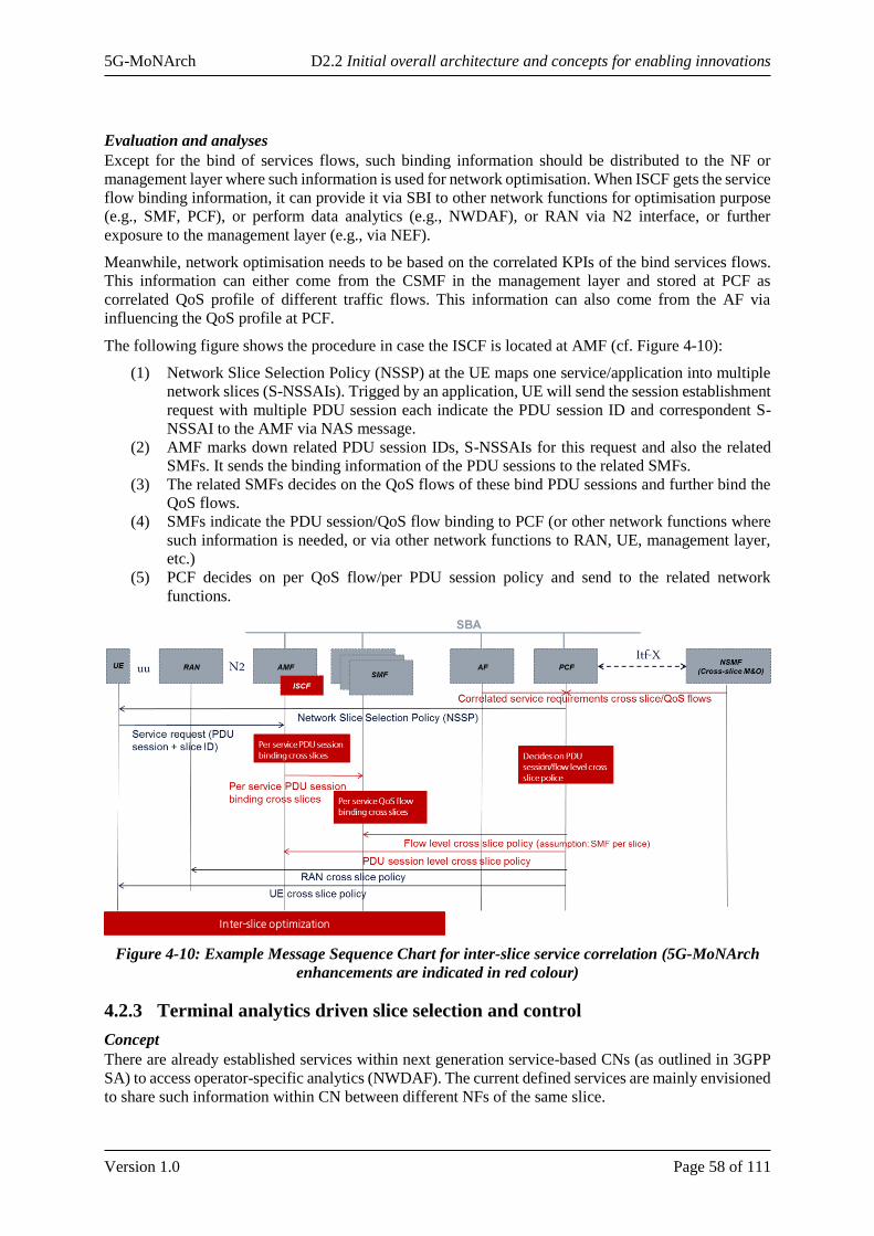
5G-MoNArch D2.2 Initial overall architecture and concepts for enabling innovations
Version 1.0 Page 58 of 111
Evaluation and analyses
Except for the bind of services flows, such binding information should be distributed to the NF or
management layer where such information is used for network optimisation. When ISCF gets the service
flow binding information, it can provide it via SBI to other network functions for optimisation purpose
(e.g., SMF, PCF), or perform data analytics (e.g., NWDAF), or RAN via N2 interface, or further
exposure to the management layer (e.g., via NEF).
Meanwhile, network optimisation needs to be based on the correlated KPIs of the bind services flows.
This information can either come from the CSMF in the management layer and stored at PCF as
correlated QoS profile of different traffic flows. This information can also come from the AF via
influencing the QoS profile at PCF.
The following figure shows the procedure in case the ISCF is located at AMF (cf. Figure 4-10):
(1) Network Slice Selection Policy (NSSP) at the UE maps one service/application into multiple
network slices (S-NSSAIs). Trigged by an application, UE will send the session establishment
request with multiple PDU session each indicate the PDU session ID and correspondent S-
NSSAI to the AMF via NAS message.
(2) AMF marks down related PDU session IDs, S-NSSAIs for this request and also the related
SMFs. It sends the binding information of the PDU sessions to the related SMFs.
(3) The related SMFs decides on the QoS flows of these bind PDU sessions and further bind the
QoS flows.
(4) SMFs indicate the PDU session/QoS flow binding to PCF (or other network functions where
such information is needed, or via other network functions to RAN, UE, management layer,
etc.)
(5) PCF decides on per QoS flow/per PDU session policy and send to the related network
functions.
Figure 4-10: Example Message Sequence Chart for inter-slice service correlation (5G-MoNArch
enhancements are indicated in red colour)
4.2.3 Terminal analytics driven slice selection and control
Concept
There are already established services within next generation service-based CNs (as outlined in 3GPP
SA) to access operator-specific analytics (NWDAF). The current defined services are mainly envisioned
to share such information within CN between different NFs of the same slice.
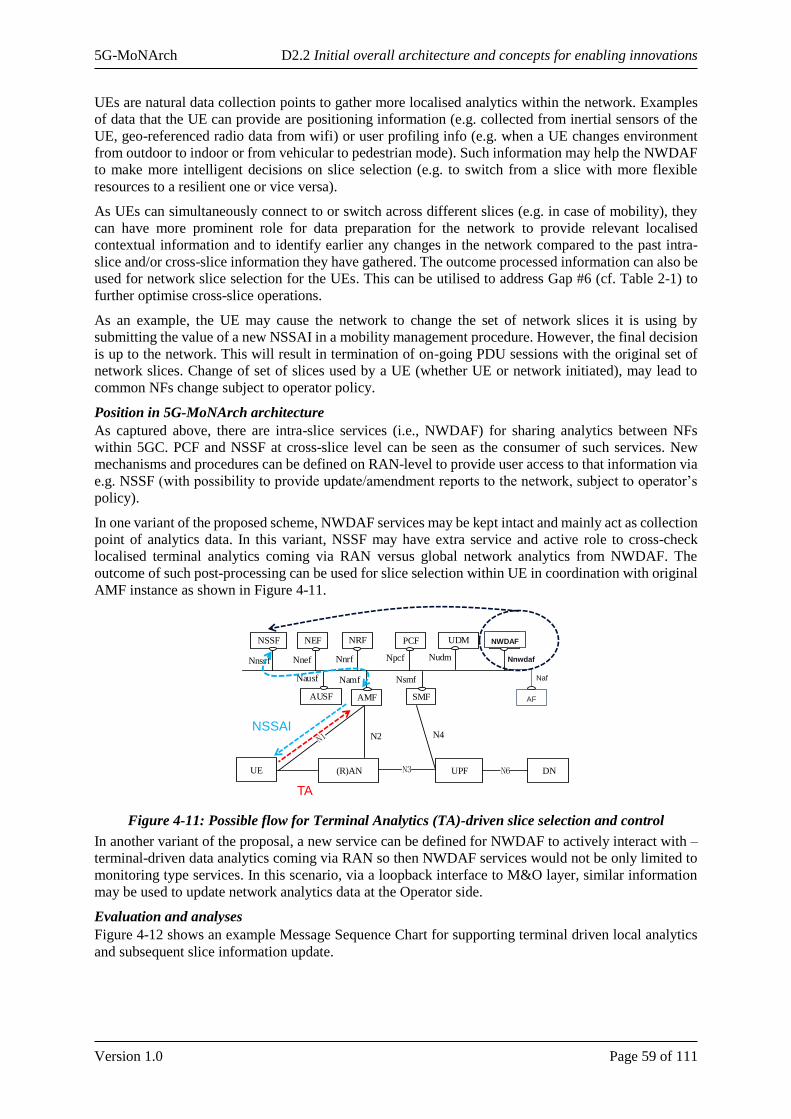
5G-MoNArch D2.2 Initial overall architecture and concepts for enabling innovations
Version 1.0 Page 59 of 111
UEs are natural data collection points to gather more localised analytics within the network. Examples
of data that the UE can provide are positioning information (e.g. collected from inertial sensors of the
UE, geo-referenced radio data from wifi) or user profiling info (e.g. when a UE changes environment
from outdoor to indoor or from vehicular to pedestrian mode). Such information may help the NWDAF
to make more intelligent decisions on slice selection (e.g. to switch from a slice with more flexible
resources to a resilient one or vice versa).
As UEs can simultaneously connect to or switch across different slices (e.g. in case of mobility), they
can have more prominent role for data preparation for the network to provide relevant localised
contextual information and to identify earlier any changes in the network compared to the past intra-
slice and/or cross-slice information they have gathered. The outcome processed information can also be
used for network slice selection for the UEs. This can be utilised to address Gap #6 (cf. Table 2-1) to
further optimise cross-slice operations.
As an example, the UE may cause the network to change the set of network slices it is using by
submitting the value of a new NSSAI in a mobility management procedure. However, the final decision
is up to the network. This will result in termination of on-going PDU sessions with the original set of
network slices. Change of set of slices used by a UE (whether UE or network initiated), may lead to
common NFs change subject to operator policy.
Position in 5G-MoNArch architecture
As captured above, there are intra-slice services (i.e., NWDAF) for sharing analytics between NFs
within 5GC. PCF and NSSF at cross-slice level can be seen as the consumer of such services. New
mechanisms and procedures can be defined on RAN-level to provide user access to that information via
e.g. NSSF (with possibility to provide update/amendment reports to the network, subject to operator’s
policy).
In one variant of the proposed scheme, NWDAF services may be kept intact and mainly act as collection
point of analytics data. In this variant, NSSF may have extra service and active role to cross-check
localised terminal analytics coming via RAN versus global network analytics from NWDAF. The
outcome of such post-processing can be used for slice selection within UE in coordination with original
AMF instance as shown in Figure 4-11.
Figure 4-11: Possible flow for Terminal Analytics (TA)-driven slice selection and control
In another variant of the proposal, a new service can be defined for NWDAF to actively interact with –
terminal-driven data analytics coming via RAN so then NWDAF services would not be only limited to
monitoring type services. In this scenario, via a loopback interface to M&O layer, similar information
may be used to update network analytics data at the Operator side.
Evaluation and analyses
Figure 4-12 shows an example Message Sequence Chart for supporting terminal driven local analytics
and subsequent slice information update.
UE (R)AN UPF
AF
AMF SMF
PCF UDM
DNN6
NRFNEF
N3
N2 N4
AUSF
Nausf Namf Nsmf
NpcfNnrfNnef Nudm Naf
NSSF
Nnssf
AF
NWDAF
Nnwdaf
Naf
NSSAI
TA
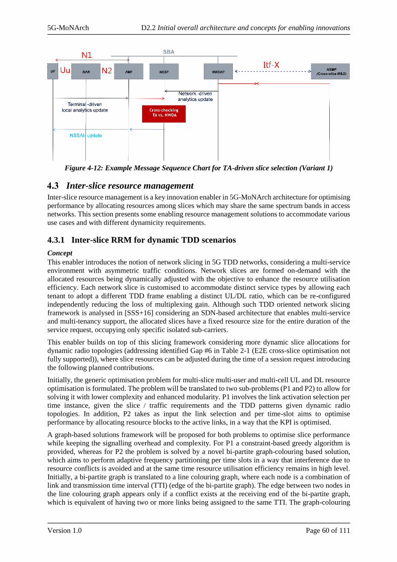
5G-MoNArch D2.2 Initial overall architecture and concepts for enabling innovations
Version 1.0 Page 60 of 111
Figure 4-12: Example Message Sequence Chart for TA-driven slice selection (Variant 1)
Inter-slice resource management
Inter-slice resource management is a key innovation enabler in 5G-MoNArch architecture for optimising
performance by allocating resources among slices which may share the same spectrum bands in access
networks. This section presents some enabling resource management solutions to accommodate various
use cases and with different dynamicity requirements.
4.3.1 Inter-slice RRM for dynamic TDD scenarios
Concept
This enabler introduces the notion of network slicing in 5G TDD networks, considering a multi-service
environment with asymmetric traffic conditions. Network slices are formed on-demand with the
allocated resources being dynamically adjusted with the objective to enhance the resource utilisation
efficiency. Each network slice is customised to accommodate distinct service types by allowing each
tenant to adopt a different TDD frame enabling a distinct UL/DL ratio, which can be re-configured
independently reducing the loss of multiplexing gain. Although such TDD oriented network slicing
framework is analysed in [SSS+16] considering an SDN-based architecture that enables multi-service
and multi-tenancy support, the allocated slices have a fixed resource size for the entire duration of the
service request, occupying only specific isolated sub-carriers.
This enabler builds on top of this slicing framework considering more dynamic slice allocations for
dynamic radio topologies (addressing identified Gap #6 in Table 2-1 (E2E cross-slice optimisation not
fully supported)), where slice resources can be adjusted during the time of a session request introducing
the following planned contributions.
Initially, the generic optimisation problem for multi-slice multi-user and multi-cell UL and DL resource
optimisation is formulated. The problem will be translated to two sub-problems (P1 and P2) to allow for
solving it with lower complexity and enhanced modularity. P1 involves the link activation selection per
time instance, given the slice / traffic requirements and the TDD patterns given dynamic radio
topologies. In addition, P2 takes as input the link selection and per time-slot aims to optimise
performance by allocating resource blocks to the active links, in a way that the KPI is optimised.
A graph-based solutions framework will be proposed for both problems to optimise slice performance
while keeping the signalling overhead and complexity. For P1 a constraint-based greedy algorithm is
provided, whereas for P2 the problem is solved by a novel bi-partite graph-colouring based solution,
which aims to perform adaptive frequency partitioning per time slots in a way that interference due to
resource conflicts is avoided and at the same time resource utilisation efficiency remains in high level.
Initially, a bi-partite graph is translated to a line colouring graph, where each node is a combination of
link and transmission time interval (TTI) (edge of the bi-partite graph). The edge between two nodes in
the line colouring graph appears only if a conflict exists at the receiving end of the bi-partite graph,
which is equivalent of having two or more links being assigned to the same TTI. The graph-colouring
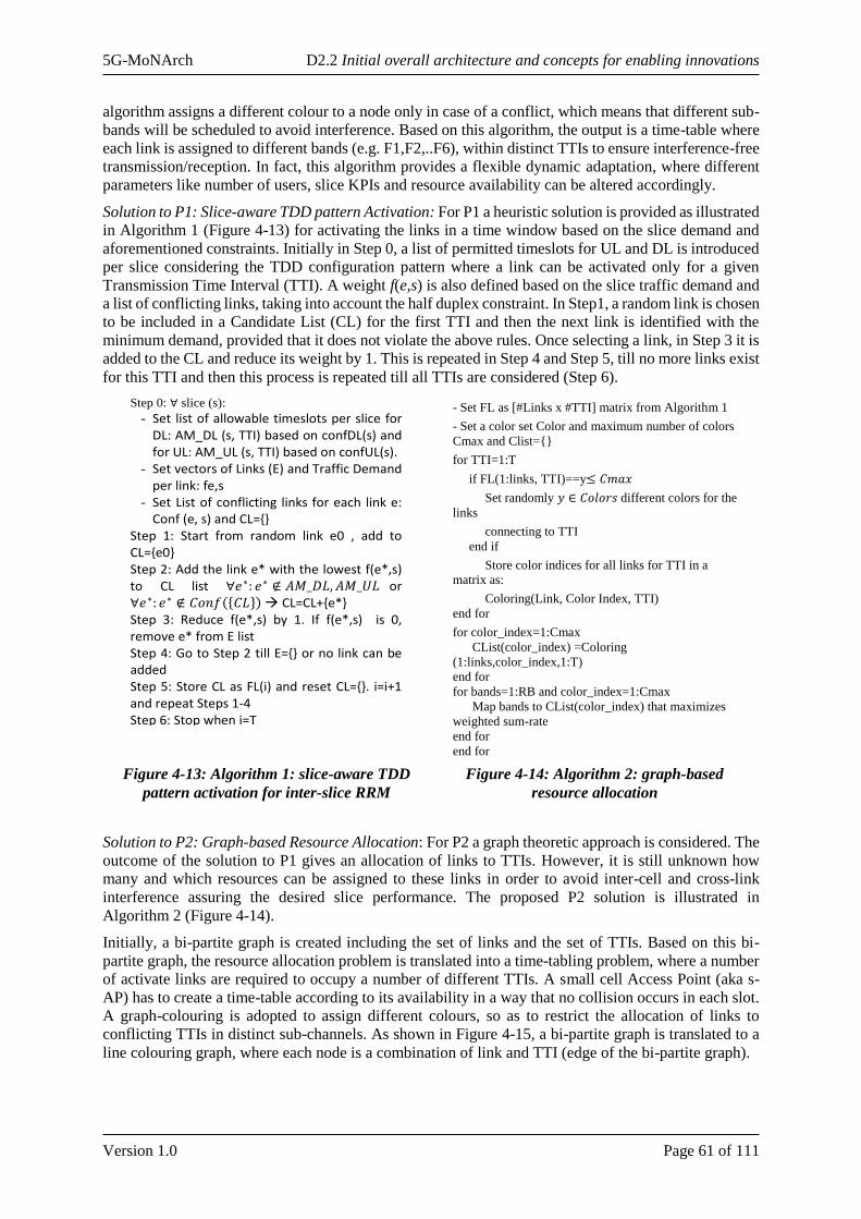
5G-MoNArch D2.2 Initial overall architecture and concepts for enabling innovations
Version 1.0 Page 61 of 111
algorithm assigns a different colour to a node only in case of a conflict, which means that different sub-
bands will be scheduled to avoid interference. Based on this algorithm, the output is a time-table where
each link is assigned to different bands (e.g. F1,F2,..F6), within distinct TTIs to ensure interference-free
transmission/reception. In fact, this algorithm provides a flexible dynamic adaptation, where different
parameters like number of users, slice KPIs and resource availability can be altered accordingly.
Solution to P1: Slice-aware TDD pattern Activation: For P1 a heuristic solution is provided as illustrated
in Algorithm 1 (Figure 4-13) for activating the links in a time window based on the slice demand and
aforementioned constraints. Initially in Step 0, a list of permitted timeslots for UL and DL is introduced
per slice considering the TDD configuration pattern where a link can be activated only for a given
Transmission Time Interval (TTI). A weight f(e,s) is also defined based on the slice traffic demand and
a list of conflicting links, taking into account the half duplex constraint. In Step1, a random link is chosen
to be included in a Candidate List (CL) for the first TTI and then the next link is identified with the
minimum demand, provided that it does not violate the above rules. Once selecting a link, in Step 3 it is
added to the CL and reduce its weight by 1. This is repeated in Step 4 and Step 5, till no more links exist
for this TTI and then this process is repeated till all TTIs are considered (Step 6).
Figure 4-13: Algorithm 1: slice-aware TDD
pattern activation for inter-slice RRM
Figure 4-14: Algorithm 2: graph-based
resource allocation
Solution to P2: Graph-based Resource Allocation: For P2 a graph theoretic approach is considered. The
outcome of the solution to P1 gives an allocation of links to TTIs. However, it is still unknown how
many and which resources can be assigned to these links in order to avoid inter-cell and cross-link
interference assuring the desired slice performance. The proposed P2 solution is illustrated in
Algorithm 2 (Figure 4-14).
Initially, a bi-partite graph is created including the set of links and the set of TTIs. Based on this bi-
partite graph, the resource allocation problem is translated into a time-tabling problem, where a number
of activate links are required to occupy a number of different TTIs. A small cell Access Point (aka s-
AP) has to create a time-table according to its availability in a way that no collision occurs in each slot.
A graph-colouring is adopted to assign different colours, so as to restrict the allocation of links to
conflicting TTIs in distinct sub-channels. As shown in Figure 4-15, a bi-partite graph is translated to a
line colouring graph, where each node is a combination of link and TTI (edge of the bi-partite graph).
Algorithm 1: Slice-aware TDD pattern Activation
Step 0: ∀ slice (s):
- Set list of allowable timeslots per slice for DL: AM_DL (s, TTI) based on confDL(s) and for UL: AM_UL (s, TTI) based on confUL(s).
- Set vectors of Links (E) and Traffic Demand per link: fe,s
- Set List of conflicting links for each link e: Conf (e, s) and CL={}
Step 1: Start from random link e0 , add to CL={e0} Step 2: Add the link e* with the lowest f(e*,s) to CL list ∀𝑒∗: 𝑒∗ ∉ 𝐴𝑀_𝐷𝐿, 𝐴𝑀_𝑈𝐿 or ∀𝑒∗: 𝑒∗ ∉ 𝐶𝑜𝑛𝑓 𝐶𝐿 CL=CL+{e*} Step 3: Reduce f(e*,s) by 1. If f(e*,s) is 0, remove e* from E list Step 4: Go to Step 2 till E={} or no link can be added Step 5: Store CL as FL(i) and reset CL={}. i=i+1 and repeat Steps 1-4 Step 6: Stop when i=T
Algorithm 2: Graph-based Resource Allocation
- Set FL as [#Links x #TTI] matrix from Algorithm 1
- Set a color set Color and maximum number of colors
Cmax and Clist={}
for TTI=1:T
if FL(1:links, TTI)==y≤ 𝐶𝑚𝑎𝑥
Set randomly 𝑦 ∈ 𝐶𝑜𝑙𝑜𝑟𝑠 different colors for the
links
connecting to TTI
end if
Store color indices for all links for TTI in a
matrix as:
Coloring(Link, Color Index, TTI)
end for
for color_index=1:Cmax
CList(color_index) =Coloring
(1:links,color_index,1:T)
end for
for bands=1:RB and color_index=1:Cmax
Map bands to CList(color_index) that maximizes
weighted sum-rate
end for
end for

5G-MoNArch D2.2 Initial overall architecture and concepts for enabling innovations
Version 1.0 Page 62 of 111
Figure 4-15: Graph colouring algorithm overview
Position in 5G-MoNArch architecture
• A common RRC functionality will be required which configures TDD patterns in a slice-aware
manner and the link activations in long term. The placement of this functionality will depend
on the dynamic radio topology and on the functional operation/capabilities of the unplanned
small cells.
• Inter-slice RRM functionality at MAC or Unified Scheduler (which can be interpreted as an
overarching layer on top of MAC for inter-slice dynamic scheduling) will be considered for
dynamic resource allocation among slices based on the configured TDD patterns. The placement
of this functionality will depend on the dynamic radio topology and on the functional
operation/capabilities/supported split of the DUs (which can be planned / unplanned small
cells).
Figure 4-16: Message sequence chart for Inter-slice RRM in dynamic TDD scenario
Evaluation and analyses
Monte Carlo system level simulations will be provided for a 5G Ultra Dense Networks (UDNs) where
resources can be shared by multiple slices with diverse KPIs (example for throughput, reliability). The
evaluation study focuses on an outdoor small cell deployment of 4 s-APs covering a hotspot area, using
the 3GPP as baseline for simulations (24 users uniformly distributed, 3GPP UMi channel, ideal
backhaul). In each s-AP the corresponding users (6 users per cell) are randomly distributed. Matlab
Monte Carlo simulations and random user drops for 500 snapshots are run. Assumed are 4 slices,
whereas each slice has different TDD pattern as slice requirement (Slice 1: 80/20, Slice 2: 70/30, Slice
Link 1 Link 2 Link K...Link 3
TTI 1 TTI 2 TTI 3 TTI 4 TTI 5 TTI 6 TTI 7 TTI 8 TTI 9 TTI 10
frame
conflict
E31
E11
E12E21
E13
Line Graph Colouring
E32E22
E23
E33
...
Node ID: Link & TTI
Color: sub-band
Link
No.
Time Periods
1st 2nd 3rd … 10th
1 F1 - F4 F3
2 F2 - F1 F2
3 F3 - F3 -
…
K F1 - F2 F1
NSMF
(Cross-slice M&O)DU
Slice info (Slice_ID, QoS
parameters, Slice
isolation requirement)
CU
UE context, measurements
Dynamic Resource Allocation
(UCI, DCI)
UE
RRC: Slice-based TDD configuration
Trigger event, e.g.,
slice request
Uu
Cross-slice M&O
F1* Itf-X
Context Info (e.g., location and DU
capability)
Inter-slice RRM
(P1)
Unified
Scheduler (P2)
Slice-aware
Link Activation pattern
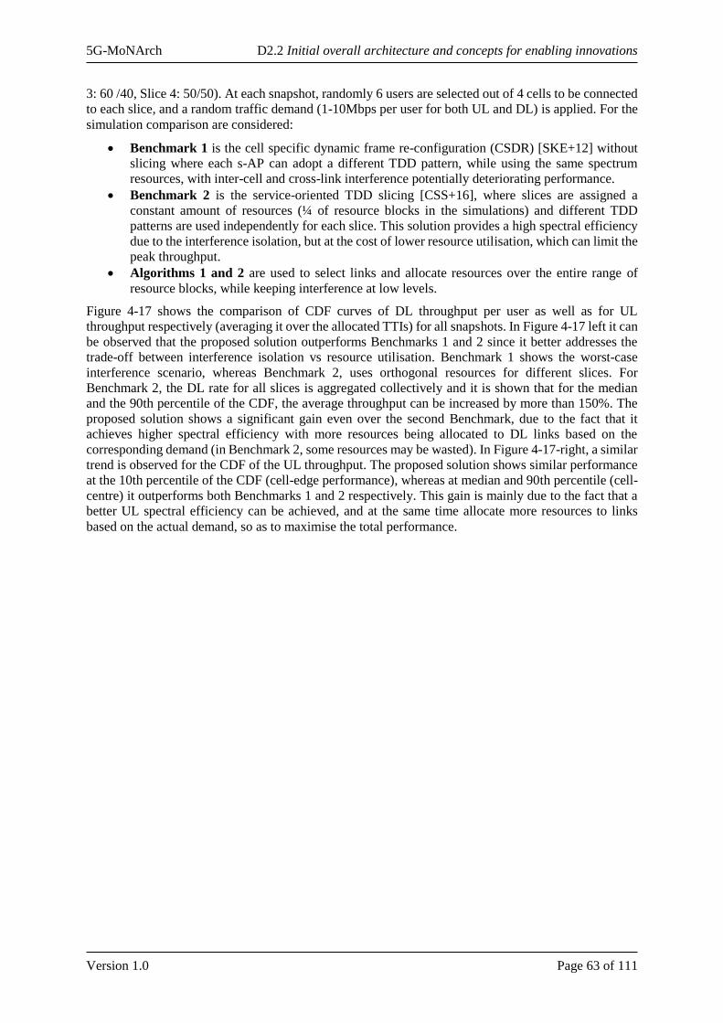
5G-MoNArch D2.2 Initial overall architecture and concepts for enabling innovations
Version 1.0 Page 63 of 111
3: 60 /40, Slice 4: 50/50). At each snapshot, randomly 6 users are selected out of 4 cells to be connected
to each slice, and a random traffic demand (1-10Mbps per user for both UL and DL) is applied. For the
simulation comparison are considered:
• Benchmark 1 is the cell specific dynamic frame re-configuration (CSDR) [SKE+12] without
slicing where each s-AP can adopt a different TDD pattern, while using the same spectrum
resources, with inter-cell and cross-link interference potentially deteriorating performance.
• Benchmark 2 is the service-oriented TDD slicing [CSS+16], where slices are assigned a
constant amount of resources (¼ of resource blocks in the simulations) and different TDD
patterns are used independently for each slice. This solution provides a high spectral efficiency
due to the interference isolation, but at the cost of lower resource utilisation, which can limit the
peak throughput.
• Algorithms 1 and 2 are used to select links and allocate resources over the entire range of
resource blocks, while keeping interference at low levels.
Figure 4-17 shows the comparison of CDF curves of DL throughput per user as well as for UL
throughput respectively (averaging it over the allocated TTIs) for all snapshots. In Figure 4-17 left it can
be observed that the proposed solution outperforms Benchmarks 1 and 2 since it better addresses the
trade-off between interference isolation vs resource utilisation. Benchmark 1 shows the worst-case
interference scenario, whereas Benchmark 2, uses orthogonal resources for different slices. For
Benchmark 2, the DL rate for all slices is aggregated collectively and it is shown that for the median
and the 90th percentile of the CDF, the average throughput can be increased by more than 150%. The
proposed solution shows a significant gain even over the second Benchmark, due to the fact that it
achieves higher spectral efficiency with more resources being allocated to DL links based on the
corresponding demand (in Benchmark 2, some resources may be wasted). In Figure 4-17-right, a similar
trend is observed for the CDF of the UL throughput. The proposed solution shows similar performance
at the 10th percentile of the CDF (cell-edge performance), whereas at median and 90th percentile (cell-
centre) it outperforms both Benchmarks 1 and 2 respectively. This gain is mainly due to the fact that a
better UL spectral efficiency can be achieved, and at the same time allocate more resources to links
based on the actual demand, so as to maximise the total performance.
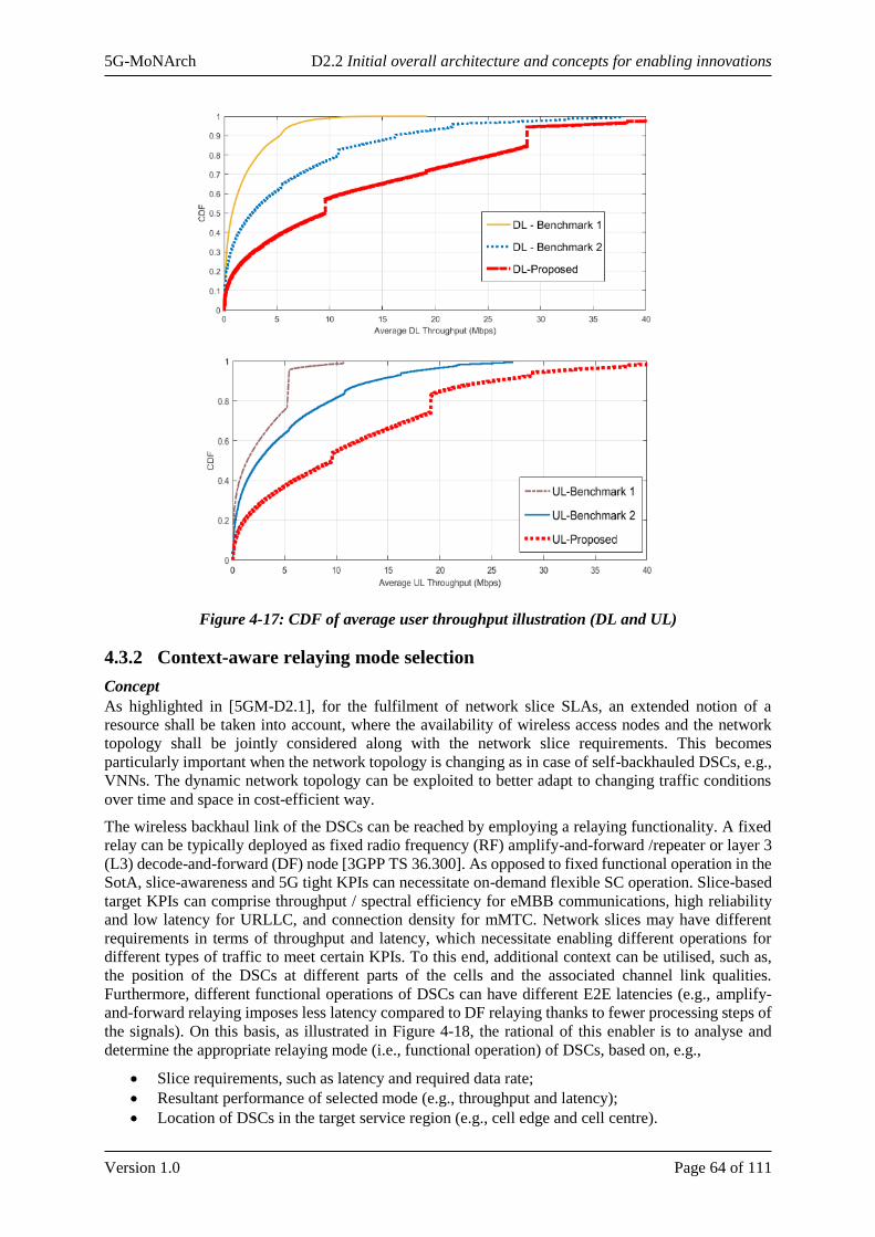
5G-MoNArch D2.2 Initial overall architecture and concepts for enabling innovations
Version 1.0 Page 64 of 111
Figure 4-17: CDF of average user throughput illustration (DL and UL)
4.3.2 Context-aware relaying mode selection
Concept
As highlighted in [5GM-D2.1], for the fulfilment of network slice SLAs, an extended notion of a
resource shall be taken into account, where the availability of wireless access nodes and the network
topology shall be jointly considered along with the network slice requirements. This becomes
particularly important when the network topology is changing as in case of self-backhauled DSCs, e.g.,
VNNs. The dynamic network topology can be exploited to better adapt to changing traffic conditions
over time and space in cost-efficient way.
The wireless backhaul link of the DSCs can be reached by employing a relaying functionality. A fixed
relay can be typically deployed as fixed radio frequency (RF) amplify-and-forward /repeater or layer 3
(L3) decode-and-forward (DF) node [3GPP TS 36.300]. As opposed to fixed functional operation in the
SotA, slice-awareness and 5G tight KPIs can necessitate on-demand flexible SC operation. Slice-based
target KPIs can comprise throughput / spectral efficiency for eMBB communications, high reliability
and low latency for URLLC, and connection density for mMTC. Network slices may have different
requirements in terms of throughput and latency, which necessitate enabling different operations for
different types of traffic to meet certain KPIs. To this end, additional context can be utilised, such as,
the position of the DSCs at different parts of the cells and the associated channel link qualities.
Furthermore, different functional operations of DSCs can have different E2E latencies (e.g., amplify-
and-forward relaying imposes less latency compared to DF relaying thanks to fewer processing steps of
the signals). On this basis, as illustrated in Figure 4-18, the rational of this enabler is to analyse and
determine the appropriate relaying mode (i.e., functional operation) of DSCs, based on, e.g.,
• Slice requirements, such as latency and required data rate;
• Resultant performance of selected mode (e.g., throughput and latency);
• Location of DSCs in the target service region (e.g., cell edge and cell centre).
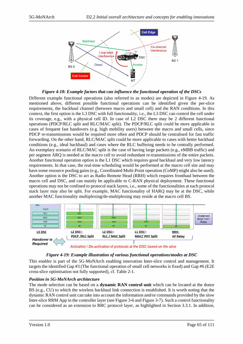
5G-MoNArch D2.2 Initial overall architecture and concepts for enabling innovations
Version 1.0 Page 65 of 111
Figure 4-18: Example factors that can influence the functional operation of the DSCs
Different example functional operations (also referred to as modes) are depicted in Figure 4-19. As
mentioned above, different possible functional operations can be identified given the per-slice
requirements, the backhaul channel (between macro and small cell) and the RAN conditions. In this
context, the first option is the L3 DSC with full functionality, i.e., the L3 DSC can control the cell under
its coverage, e.g., with a physical cell ID. In case of L2 DSC there may be 2 different functional
operations (PDCP/RLC split and RLC/MAC split). The PDCP/RLC split could be more applicable in
cases of frequent fast handovers (e.g. high mobility users) between the macro and small cells, since
PDCP re-transmissions would be required more often and PDCP should be centralised for fast traffic
forwarding. On the other hand, RLC/MAC split could be more applicable to cases with better backhaul
conditions (e.g., ideal backhaul) and cases where the RLC buffering needs to be centrally performed.
An exemplary scenario of RLC/MAC split is the case of having large packets (e.g., eMBB traffic) and
per segment ARQ is needed at the macro cell to avoid redundant re-transmissions of the entire packets.
Another functional operation option is the L1 DSC which requires good backhaul and very low latency
requirements. In that case, the real-time scheduling would be performed at the macro cell site and may
have some resource pooling gains (e.g., Coordinated Multi-Point operation (CoMP) might also be used).
Another option is the DSC to act as Radio Remote Head (RRH) which requires fronthaul between the
macro cell and DSC, and can mainly be applicable to C-RAN physical deployment. These functional
operations may not be confined to protocol stack layers, i.e., some of the functionalities at each protocol
stack layer may also be split. For example, MAC functionality of HARQ may be at the DSC, while
another MAC functionality multiplexing/de-multiplexing may reside at the macro cell BS.
Figure 4-19: Example illustration of various functional operations/modes at DSC
This enabler is part of the 5G-MoNArch enabling innovation Inter-slice control and management. It
targets the identified Gap #3 (The functional operation of small cell networks is fixed) and Gap #6 (E2E
cross-slice optimisation not fully supported), cf. Table 2-1.
Position in 5G-MoNArch architecture
The mode selection can be based on a dynamic RAN control unit which can be located at the donor
BS (e.g., CU) to which the wireless backhaul link connection is established. It is worth noting that the
dynamic RAN control unit can take into account the information and/or commands provided by the slow
Inter-slice RRM App in the controller layer (see Figure 3-6 and Figure 3-7). Such a control functionality
can be considered as an extension to RRC protocol layer, as highlighted in Section 3.3.1. In addition,

5G-MoNArch D2.2 Initial overall architecture and concepts for enabling innovations
Version 1.0 Page 66 of 111
network slicing management functions (e.g., Cross-slice M&O function) can also be considered, which
are responsible from RAN configuration. An example operation is depicted by a MSC in Figure 4-20.
Figure 4-20: Message sequence chart for the operation of the context-aware relay mode selection
Evaluation and analyses
The evaluation of this enabler will comprise a joint optimisation of the achievable data rate and the
induced protocol processing delays considering different relaying modes and the location of the DSC in
a macro cell. For the protocol processing delays existing standard specifications are to be utilised, e.g.,
LTE-A, and NR depending on the availability of the ongoing specifications. Accordingly, the overall
performances of the different modes can be compared with the network slice requirements and the
selection of the relaying mode can be justified. Such and similar evaluations will be presented in the
final deliverable D2.3.
4.3.3 Slice-aware RAT selection
Concept
Network slicing enables to tailor a network instance to the specific requirements of a future 5G service.
In this context, RRM will be a complex task, because the 5G network will integrate different RATs,
each one with its specific characteristics in terms of e.g. coverage and capacity (see Figure 4-21). The
appropriate configuration of the RAT and the management of the associated resources is a challenging
task, when considering the heterogeneous requirements of the diverse 5G services.
In LTE system, cell range expansion has been used as a way to offload traffic from macro cells to small
cells and boost the network capacity [ONY+11]. The concept foresees a similar scheme to balance traffic
across multiple RATs, where biased received powers related to different RATs are compared at the UEs
in order to select the most appropriated RAT to use.
In LTE, the same bias is used at different UEs to compare the received powers and associate to a nearby
small cell or the macro cell, accordingly. However, although some UEs may benefit of the improved
capacity offered by small cells, other UEs may rather require reliable coverage, offered by the macro
cell signal. In addition, when considering millimetre-wave (mmW) small cells in future 5G networks it
is of paramount importance to take into account their propagation characteristics, high path loss and
sensibility to blockages, which can be detrimental for the user performance. This is particularly true for
URLLC and Vehicle to Everything (V2X) communications. Therefore, this study focuses on Gap #5 of
Table 2-1.
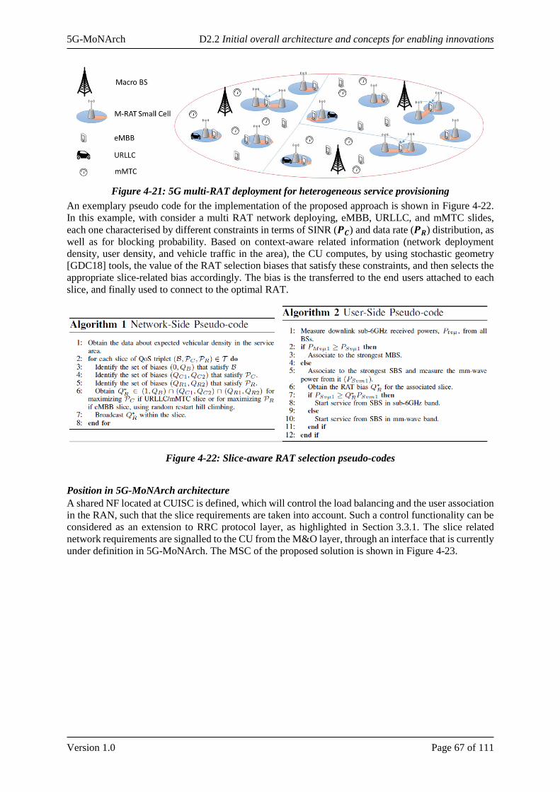
5G-MoNArch D2.2 Initial overall architecture and concepts for enabling innovations
Version 1.0 Page 67 of 111
Figure 4-21: 5G multi-RAT deployment for heterogeneous service provisioning
An exemplary pseudo code for the implementation of the proposed approach is shown in Figure 4-22.
In this example, with consider a multi RAT network deploying, eMBB, URLLC, and mMTC slides,
each one characterised by different constraints in terms of SINR (𝑷𝑪) and data rate (𝑷𝑹) distribution, as
well as for blocking probability. Based on context-aware related information (network deployment
density, user density, and vehicle traffic in the area), the CU computes, by using stochastic geometry
[GDC18] tools, the value of the RAT selection biases that satisfy these constraints, and then selects the
appropriate slice-related bias accordingly. The bias is the transferred to the end users attached to each
slice, and finally used to connect to the optimal RAT.
Figure 4-22: Slice-aware RAT selection pseudo-codes
Position in 5G-MoNArch architecture
A shared NF located at CUISC is defined, which will control the load balancing and the user association
in the RAN, such that the slice requirements are taken into account. Such a control functionality can be
considered as an extension to RRC protocol layer, as highlighted in Section 3.3.1. The slice related
network requirements are signalled to the CU from the M&O layer, through an interface that is currently
under definition in 5G-MoNArch. The MSC of the proposed solution is shown in Figure 4-23.
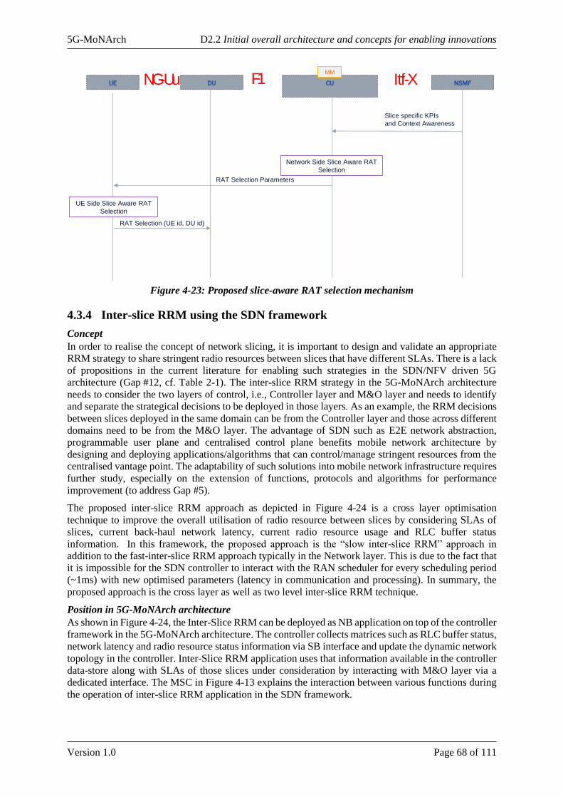
5G-MoNArch D2.2 Initial overall architecture and concepts for enabling innovations
Version 1.0 Page 68 of 111
Figure 4-23: Proposed slice-aware RAT selection mechanism
4.3.4 Inter-slice RRM using the SDN framework
Concept
In order to realise the concept of network slicing, it is important to design and validate an appropriate
RRM strategy to share stringent radio resources between slices that have different SLAs. There is a lack
of propositions in the current literature for enabling such strategies in the SDN/NFV driven 5G
architecture (Gap #12, cf. Table 2-1). The inter-slice RRM strategy in the 5G-MoNArch architecture
needs to consider the two layers of control, i.e., Controller layer and M&O layer and needs to identify
and separate the strategical decisions to be deployed in those layers. As an example, the RRM decisions
between slices deployed in the same domain can be from the Controller layer and those across different
domains need to be from the M&O layer. The advantage of SDN such as E2E network abstraction,
programmable user plane and centralised control plane benefits mobile network architecture by
designing and deploying applications/algorithms that can control/manage stringent resources from the
centralised vantage point. The adaptability of such solutions into mobile network infrastructure requires
further study, especially on the extension of functions, protocols and algorithms for performance
improvement (to address Gap #5).
The proposed inter-slice RRM approach as depicted in Figure 4-24 is a cross layer optimisation
technique to improve the overall utilisation of radio resource between slices by considering SLAs of
slices, current back-haul network latency, current radio resource usage and RLC buffer status
information. In this framework, the proposed approach is the “slow inter-slice RRM” approach in
addition to the fast-inter-slice RRM approach typically in the Network layer. This is due to the fact that
it is impossible for the SDN controller to interact with the RAN scheduler for every scheduling period
(~1ms) with new optimised parameters (latency in communication and processing). In summary, the
proposed approach is the cross layer as well as two level inter-slice RRM technique.
Position in 5G-MoNArch architecture
As shown in Figure 4-24, the Inter-Slice RRM can be deployed as NB application on top of the controller
framework in the 5G-MoNArch architecture. The controller collects matrices such as RLC buffer status,
network latency and radio resource status information via SB interface and update the dynamic network
topology in the controller. Inter-Slice RRM application uses that information available in the controller
data-store along with SLAs of those slices under consideration by interacting with M&O layer via a
dedicated interface. The MSC in Figure 4-13 explains the interaction between various functions during
the operation of inter-slice RRM application in the SDN framework.
UE DU CU NSMF
Slice specific KPIs
and Context Awareness
Network Side Slice Aware RAT
Selection
RAT Selection Parameters
F1 Itf-XNG-UuMM
UE Side Slice Aware RAT
Selection
RAT Selection (UE id, DU id)
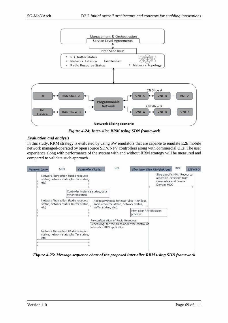
5G-MoNArch D2.2 Initial overall architecture and concepts for enabling innovations
Version 1.0 Page 69 of 111
Figure 4-24: Inter-slice RRM using SDN framework
Evaluation and analysis
In this study, RRM strategy is evaluated by using SW emulators that are capable to emulate E2E mobile
network managed/operated by open source SDN/NFV controllers along with commercial UEs. The user
experience along with performance of the system with and without RRM strategy will be measured and
compared to validate such approach.
Figure 4-25: Message sequence chart of the proposed inter-slice RRM using SDN framework

5G-MoNArch D2.2 Initial overall architecture and concepts for enabling innovations
Version 1.0 Page 70 of 111
4.3.5 Big data analytics for resource assignment
Concept
Chapter 3 described an overall architecture for instantiating multiple network slices, along some
possible optimisations of the interactions among the functions in a VNF chain. However, when setting
up a slice without stringent service requirements, one of the key desired features will be that of elasticity;
this is needed in all cases where resource overprovisioning is not a valid option either due to the actual
resource availability (e.g., in the edge of the network) or due to the dynamic nature of network load,
which makes an efficient network slice dimensioning difficult. In those cases, temporal and spatial
traffic fluctuations may require that the network dimensions resources such that, in case of peak
demands, the network adapts its operation and re-distributes available resources as needed.
These load fluctuations usually characterise each slice. In this context, statistical multiplexing gains can
be improved by applying elasticity to simultaneously serve multiple slices using the same set of physical
resources (in conjunction with the cloud-aware protocol stack described in Section 4.1.1). This has a
direct impact on the number of network slices that can be hosted within the same infrastructure and, in
turn, allows to exploit complementarities across slices, yielding larger resource utilisation efficiency and
high gains in network deployment investments (as long as cross-slice resource orchestration is optimally
realised).
Position in 5G-MoNArch architecture
This behaviour is implemented by orchestration algorithms implemented in the Cross-slice M&O
module. NFV-Os orchestrate VNFs on the available resources according to the available resources and
their elasticity. For example, resources may be equally shared initially, then, in case of peak demands,
the Cross-slice M&O can re-assign resources taking advantage of different distributions of loads. In this
case, resources are borrowed from slices in trough load. The behaviour of the various elastic slices when
the resources needed to accommodate their peak demands exceed the originally assigned ones is driven
by the elastic operation.
Big Data engines can be used to perform the operation described above in an automated fashion. By
studying the past load of different network slices, this engine can identify the most usual time interval
and locations in which a network slice experience higher peak demands or, on the other hand, lower
activities. Summarising, the foundation of this work lies in the network slice characterisation.
An accurate characterisation of traffic demands over a given area supports a more efficient planning of
network resources. For example, in case of capacity-limited deployments, accurate characterisation
supports a very efficient deployment of resources over time. Therefore, this kind of analysis will be
beneficial also for the economic feasibility of multi service deployments. As depicted in Figure 4-26,
the resource assignment procedure takes into account inputs coming from data monitoring modules
deployed in the core network (such as the NWDAF).
Evaluation and analyses
The evaluation performed for this activity will be performed in two steps. Firstly, using a large-scale
dataset, the activity patterns of different network slices will be evaluated, identifying possible
complementarities in the load they impose on the network. Besides the network metrics, also other
metrics such as cloud resources consumption and the related costs will be evaluated. Secondly, based
on these finding, it will be assessed what would be the needed interfaces towards the orchestration and
the network control layers that a Big Data driven resource assignment algorithm needs.
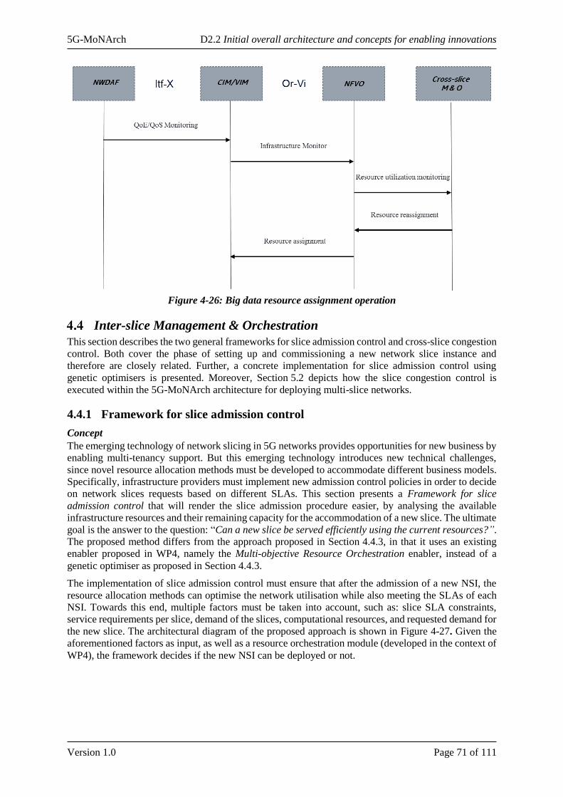
5G-MoNArch D2.2 Initial overall architecture and concepts for enabling innovations
Version 1.0 Page 71 of 111
Figure 4-26: Big data resource assignment operation
Inter-slice Management & Orchestration
This section describes the two general frameworks for slice admission control and cross-slice congestion
control. Both cover the phase of setting up and commissioning a new network slice instance and
therefore are closely related. Further, a concrete implementation for slice admission control using
genetic optimisers is presented. Moreover, Section 5.2 depicts how the slice congestion control is
executed within the 5G-MoNArch architecture for deploying multi-slice networks.
4.4.1 Framework for slice admission control
Concept
The emerging technology of network slicing in 5G networks provides opportunities for new business by
enabling multi-tenancy support. But this emerging technology introduces new technical challenges,
since novel resource allocation methods must be developed to accommodate different business models.
Specifically, infrastructure providers must implement new admission control policies in order to decide
on network slices requests based on different SLAs. This section presents a Framework for slice
admission control that will render the slice admission procedure easier, by analysing the available
infrastructure resources and their remaining capacity for the accommodation of a new slice. The ultimate
goal is the answer to the question: “Can a new slice be served efficiently using the current resources?”.
The proposed method differs from the approach proposed in Section 4.4.3, in that it uses an existing
enabler proposed in WP4, namely the Multi-objective Resource Orchestration enabler, instead of a
genetic optimiser as proposed in Section 4.4.3.
The implementation of slice admission control must ensure that after the admission of a new NSI, the
resource allocation methods can optimise the network utilisation while also meeting the SLAs of each
NSI. Towards this end, multiple factors must be taken into account, such as: slice SLA constraints,
service requirements per slice, demand of the slices, computational resources, and requested demand for
the new slice. The architectural diagram of the proposed approach is shown in Figure 4-27. Given the
aforementioned factors as input, as well as a resource orchestration module (developed in the context of
WP4), the framework decides if the new NSI can be deployed or not.
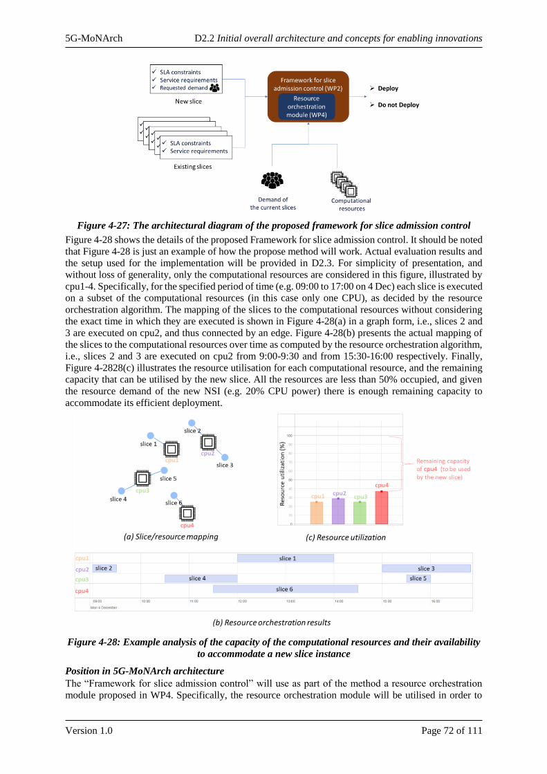
5G-MoNArch D2.2 Initial overall architecture and concepts for enabling innovations
Version 1.0 Page 72 of 111
Figure 4-27: The architectural diagram of the proposed framework for slice admission control
Figure 4-28 shows the details of the proposed Framework for slice admission control. It should be noted
that Figure 4-28 is just an example of how the propose method will work. Actual evaluation results and
the setup used for the implementation will be provided in D2.3. For simplicity of presentation, and
without loss of generality, only the computational resources are considered in this figure, illustrated by
cpu1-4. Specifically, for the specified period of time (e.g. 09:00 to 17:00 on 4 Dec) each slice is executed
on a subset of the computational resources (in this case only one CPU), as decided by the resource
orchestration algorithm. The mapping of the slices to the computational resources without considering
the exact time in which they are executed is shown in Figure 4-28(a) in a graph form, i.e., slices 2 and
3 are executed on cpu2, and thus connected by an edge. Figure 4-28(b) presents the actual mapping of
the slices to the computational resources over time as computed by the resource orchestration algorithm,
i.e., slices 2 and 3 are executed on cpu2 from 9:00-9:30 and from 15:30-16:00 respectively. Finally,
Figure 4-2828(c) illustrates the resource utilisation for each computational resource, and the remaining
capacity that can be utilised by the new slice. All the resources are less than 50% occupied, and given
the resource demand of the new NSI (e.g. 20% CPU power) there is enough remaining capacity to
accommodate its efficient deployment.
Figure 4-28: Example analysis of the capacity of the computational resources and their availability
to accommodate a new slice instance
Position in 5G-MoNArch architecture
The “Framework for slice admission control” will use as part of the method a resource orchestration
module proposed in WP4. Specifically, the resource orchestration module will be utilised in order to

5G-MoNArch D2.2 Initial overall architecture and concepts for enabling innovations
Version 1.0 Page 73 of 111
identify how much of the resources are utilised by the current slices and how many resources are free
on average, so as to take the decision of if the new slice can be served efficiently using the current
resources. This means that the “Framework for slice admission control” will be implemented at the
orchestrator level, and in particular in the CROSS S.SOMO module inside the NSMF (see
Section 3.3.3), in order to manage virtual resources across different slices and make sure that the
requirements of accepted slices are satisfied.
Evaluation and analyses
As mentioned in the previous paragraph, the “Framework for slice admission control” will use as part
of the method a resource orchestration module proposed in WP4. Specifically, the resource orchestration
module that will be used is the “Multi-objective slice-aware resource orchestration”. This module takes
into consideration multiple objectives in the form of KPI constraints regarding either the entire network,
or specific slices based on their SLAs. Thus, given a current state of the network, the resources that are
on average free, and a new slice with specific requirements, the algorithm can answer the following
question with a yes/no response: Can a new slice be served efficiently using the current resources? An
example of this approach is provided in Figure 4-28. Actual evaluation results will be presented in D2.3.
4.4.2 Framework for cross-slice congestion control
Concept
Network slicing is realised by deploying a set of VNFs requiring resources such as radio, computing,
and storage resources. The Cross-slice Congestion Control (CSCC) function shown in Figure 4-29 is
responsible of accepting or dropping a new slice request by controlling resource availability, slice
priorities, and queue state.
The CSCC may decide, based on the service level requirements of a class, to scale down the allocated
resources to one or multiples slices in order to accept a larger number of requests, which have high
priority. The proposed CSCC has to be able to foresee the impact of a decision on the overall system
performance [PJD+15]. This intelligence is ensured by using reinforcement learning (RL) techniques
that allow to make the optimal decisions maximising resources utilisation [GBL+12]. Therefore, this
study focuses on Gaps #5, #6, and #12, cf. Table 2-1.
Figure 4-29: Proposed Cross-slice Admission and Congestion Control framework
Position in 5G-MoNArch architecture
The CSCC will be implemented at the orchestrator level, and in particular in the CROSS S. SOMO
module inside the NSMF (cf. Section 3.3.3.2) as it enables to manage virtual resources across different
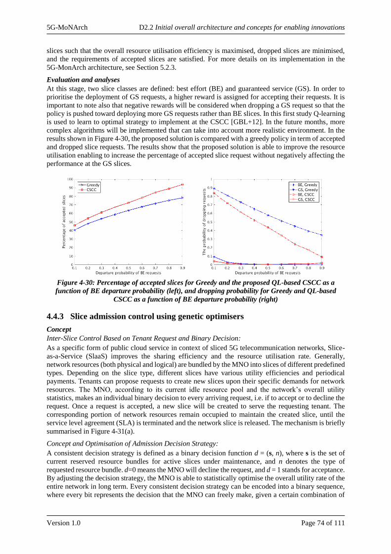
5G-MoNArch D2.2 Initial overall architecture and concepts for enabling innovations
Version 1.0 Page 74 of 111
slices such that the overall resource utilisation efficiency is maximised, dropped slices are minimised,
and the requirements of accepted slices are satisfied. For more details on its implementation in the
5G-MonArch architecture, see Section 5.2.3.
Evaluation and analyses
At this stage, two slice classes are defined: best effort (BE) and guaranteed service (GS). In order to
prioritise the deployment of GS requests, a higher reward is assigned for accepting their requests. It is
important to note also that negative rewards will be considered when dropping a GS request so that the
policy is pushed toward deploying more GS requests rather than BE slices. In this first study Q-learning
is used to learn to optimal strategy to implement at the CSCC [GBL+12]. In the future months, more
complex algorithms will be implemented that can take into account more realistic environment. In the
results shown in Figure 4-30, the proposed solution is compared with a greedy policy in term of accepted
and dropped slice requests. The results show that the proposed solution is able to improve the resource
utilisation enabling to increase the percentage of accepted slice request without negatively affecting the
performance at the GS slices.
Figure 4-30: Percentage of accepted slices for Greedy and the proposed QL-based CSCC as a
function of BE departure probability (left), and dropping probability for Greedy and QL-based
CSCC as a function of BE departure probability (right)
4.4.3 Slice admission control using genetic optimisers
Concept
Inter-Slice Control Based on Tenant Request and Binary Decision:
As a specific form of public cloud service in context of sliced 5G telecommunication networks, Slice-
as-a-Service (SlaaS) improves the sharing efficiency and the resource utilisation rate. Generally,
network resources (both physical and logical) are bundled by the MNO into slices of different predefined
types. Depending on the slice type, different slices have various utility efficiencies and periodical
payments. Tenants can propose requests to create new slices upon their specific demands for network
resources. The MNO, according to its current idle resource pool and the network’s overall utility
statistics, makes an individual binary decision to every arriving request, i.e. if to accept or to decline the
request. Once a request is accepted, a new slice will be created to serve the requesting tenant. The
corresponding portion of network resources remain occupied to maintain the created slice, until the
service level agreement (SLA) is terminated and the network slice is released. The mechanism is briefly
summarised in Figure 4-31(a).
Concept and Optimisation of Admission Decision Strategy:
A consistent decision strategy is defined as a binary decision function d = (s, n), where s is the set of
current reserved resource bundles for active slices under maintenance, and n denotes the type of
requested resource bundle. d=0 means the MNO will decline the request, and d = 1 stands for acceptance.
By adjusting the decision strategy, the MNO is able to statistically optimise the overall utility rate of the
entire network in long term. Every consistent decision strategy can be encoded into a binary sequence,
where every bit represents the decision that the MNO can freely make, given a certain combination of
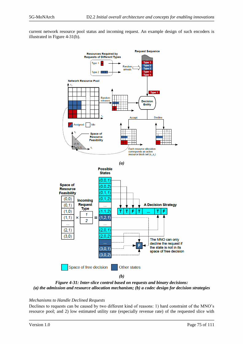
5G-MoNArch D2.2 Initial overall architecture and concepts for enabling innovations
Version 1.0 Page 75 of 111
current network resource pool status and incoming request. An example design of such encoders is
illustrated in Figure 4-31(b).
(a)
(b)
Figure 4-31: Inter-slice control based on requests and binary decisions:
(a) the admission and resource allocation mechanism; (b) a codec design for decision strategies
Mechanisms to Handle Declined Requests
Declines to requests can be caused by two different kind of reasons: 1) hard constraint of the MNO’s
resource pool; and 2) low estimated utility rate (especially revenue rate) of the requested slice with

5G-MoNArch D2.2 Initial overall architecture and concepts for enabling innovations
Version 1.0 Page 76 of 111
respect to the opportunity cost (the utility of slices that may potentially be created in the future with the
network resources required by the current request).
In the first case, it is impossible to immediately satisfy the tenant’s demand without upgrading the
resource pool. To mitigate rejecting the tenant and therefore losing the client, the MNO can offer a
delayed service. Possible approaches to implement this include:
• A random delay protocol where the tenant resends its declined request after a random delay
(similar to the random-access procedure in RAN);
• A queuing mechanism where the declined requests are buffered in a queue (or a pool) to wait
for released resources.
In the second case, besides the delayed service, a bidding mechanism can be integrated where a tenant
can keep increasing the payment it offers for the requested slice until it exceeds an upper bound or
eventually gets accepted by the MNO.
Position in 5G-MoNArch architecture
The Genetic Slice Admission Control particularly affects the 5G-MoNArch M&O layer. The overall
procedure involves the NFV MANO functions, Cross-slice M&O function within NSMF, XSC in the
Controller layer as well as BSS functions, applications, and services of the Service layer. The call flow
for slice admission control using genetic optimisation is depicted in.
Evaluation and analyses
A genetic method is proposed, where each feasible slicing strategy is encoded to a binary sequence. A
population of randomly generated strategies are initialised and parallel evaluated in real-time with
respect to their long-term network utility rate. A genetic algorithm (GA), which includes the three steps
of reproduction, crossover and mutation, then applies to the current population, so that a new generation
of candidate strategies will be created. This process runs in iterations so that the entire population
evolves to a good set of strategies with high utility rates, and the best strategy in the population
approaches to the global optimum through a winding process. The overall procedure is illustrated in
Figure 4-32 Figure 4-33. The proposed method is model-free, can be flexibly applied to different (and
even heterogeneous) constructions of utility function. It was verified to be effective, fast-converging
and robust against inconsistent environment. Figure 4-34 shows the performance evolution of the entire
population of strategies. Figure 4-35 shows the performance of the best (deployed) candidate in non-
consistent network traffic scenario, three “naïve” strategies and a static optimum are also tested as
benchmark. More details about the proposed method, the simulation design, more evaluation results,
and further analysis can be found in [HJS18].
Figure 4-32: Message flow chart of deploying genetic slice admission control
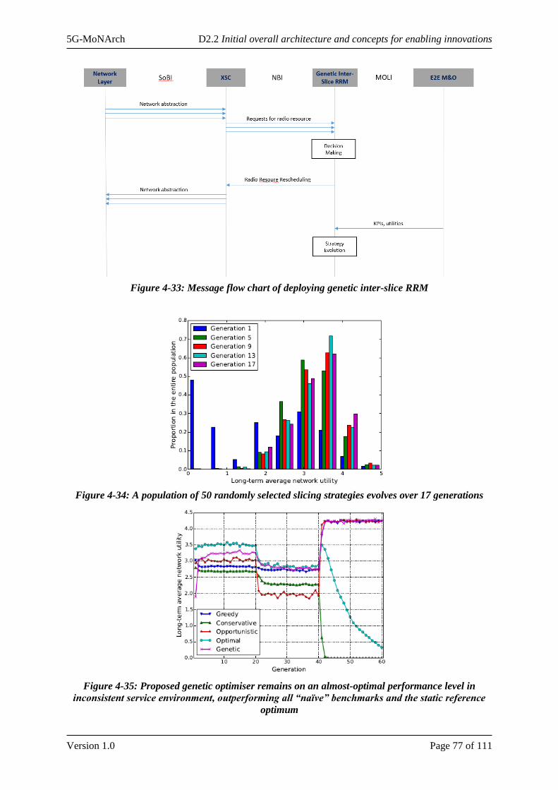
5G-MoNArch D2.2 Initial overall architecture and concepts for enabling innovations
Version 1.0 Page 77 of 111
Figure 4-33: Message flow chart of deploying genetic inter-slice RRM
Figure 4-34: A population of 50 randomly selected slicing strategies evolves over 17 generations
Figure 4-35: Proposed genetic optimiser remains on an almost-optimal performance level in
inconsistent service environment, outperforming all “naïve” benchmarks and the static reference
optimum
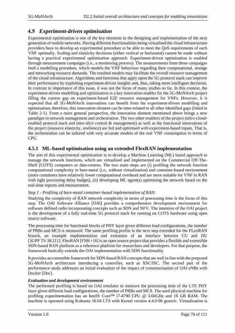
5G-MoNArch D2.2 Initial overall architecture and concepts for enabling innovations
Version 1.0 Page 78 of 111
Experiment-driven optimisation
Experimental optimisation is one of the key elements in the designing and implementation of the next
generation of mobile networks. Having different functionalities being virtualised the cloud infrastructure
providers have to develop an experimental procedure to be able to meet the QoS requirements of each
VNF optimally. Scaling and elasticity decisions (either vertical or horizontal) cannot be made without
having a practical experimental optimisation approach. Experiment-driven optimisation is enabled
through measurement campaigns (i.e., a monitoring process). The measurements from these campaigns
feed a modelling procedure, which models the VNF behaviour regarding their computational, storage
and networking resource demands. The resulted models may facilitate the overall resource management
of the cloud infrastructure. Algorithms and functions that apply upon the 5G protocol stack can improve
their performance by exploiting experiment-driven insights and, thus, taking more intelligent decisions.
In contrast to importance of this issue, it was not the focus of many studies so far. In this context, the
experiment-driven modelling and optimisation is a key innovation enabler for the 5G-MoNArch project
filling the current gap on experiment-based E2E resource management for VNFs. However, it is
expected that all 5G-MoNArch innovations can benefit from the experiment-driven modelling and
optimisation; therefore, this innovation element can be inter-related to all other identified gaps (listed in
Table 2-1). From a more general perspective, the innovation element mentioned above brings a new
paradigm in network management and orchestration. The two other enablers of the project (telco-cloud-
enabled protocol stack and inter-slice control & management) as well as the functional innovations of
the project (resource elasticity, resilience) are fed and optimised with experiment-based inputs. That is,
the orchestration can be tailored with very accurate models of the real VNF consumption in terms of
CPU.
4.5.1 ML-based optimisation using an extended FlexRAN implementation
The aim of this experimental optimisation is to develop a Machine Learning (ML) based approach to
manage the network functions, which are virtualised and implemented on the Commercial Off-The-
Shelf (COTS) computers or data-centres. The two main steps are (i) profiling the network function
computational complexity in bare-metal (i.e., without virtualisation) and container-based environment
(since containers have relatively lower computational overhead and are more suitable for VNF in RAN
with tight processing delay budget), (ii) developing ML agent(s) optimising the network based on the
real-time reports and measurement.
Step 1 - Profiling of bare-metal container-based implementation of RAN:
Studying the complexity of RAN network complexity in terms of processing time is the focus of this
step. The OAI Software Alliance [OAI] provides a comprehensive development environment for
software defined radio incorporating concepts such as SDN and NFV. The intention of the OAI project
is the development of a fully real-time 5G protocol stack for running on COTS hardware using open
source software.
The processing time for functional blocks of PHY layer given different load configurations, the number
of PRBs and MCS is measured. The same profiling profile in the next step extended for the FLexRAN
branch, an example implementation and extension of an interface between CU and DU
[3GPP TS 38.211]. FlexRAN [FNK+16] is an open source project that provides a flexible and extensible
SDN-based RAN platform as a reference platform for researchers and developers. For that purpose, the
framework basically extends the OAI implementation with SDN functionality
It provides an extensible framework for SDN-based RAN concepts that are well in line with the proposed
5G-MoNArch architecture introducing a controller, such as XSC/ISC. The second part of the
performance study addresses an initial evaluation of the impact of containerisation of OAI eNBs with
Docker [Doc].
Evaluation and development environment
The performed profiling is based on OAI emulator to measure the processing time of the LTE PHY
layer given different load configurations, the number of PRBs and MCS. The used physical machine for
profiling experimentation has an Intel® Core™ i7-4790 CPU @ 3.60GHz and 16 GB RAM. The
machine is operated using Kubuntu 16.04 LTS with Kernel version 4.4.0-96 generic. Virtualisation is
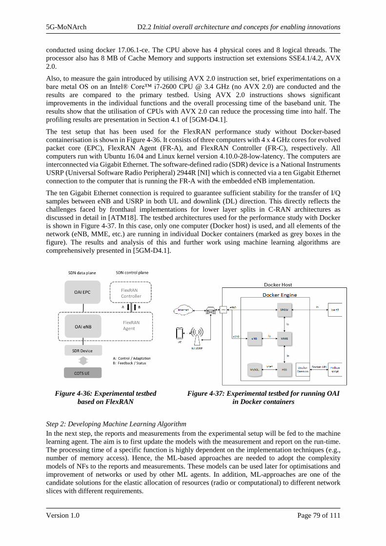
5G-MoNArch D2.2 Initial overall architecture and concepts for enabling innovations
Version 1.0 Page 79 of 111
conducted using docker 17.06.1-ce. The CPU above has 4 physical cores and 8 logical threads. The
processor also has 8 MB of Cache Memory and supports instruction set extensions SSE4.1/4.2, AVX
2.0.
Also, to measure the gain introduced by utilising AVX 2.0 instruction set, brief experimentations on a
bare metal OS on an Intel® Core™ i7-2600 CPU @ 3.4 GHz (no AVX 2.0) are conducted and the
results are compared to the primary testbed. Using AVX 2.0 instructions shows significant
improvements in the individual functions and the overall processing time of the baseband unit. The
results show that the utilisation of CPUs with AVX 2.0 can reduce the processing time into half. The
profiling results are presentation in Section 4.1 of [5GM-D4.1].
The test setup that has been used for the FlexRAN performance study without Docker-based
containerisation is shown in Figure 4-36. It consists of three computers with 4 x 4 GHz cores for evolved
packet core (EPC), FlexRAN Agent (FR-A), and FlexRAN Controller (FR-C), respectively. All
computers run with Ubuntu 16.04 and Linux kernel version 4.10.0-28-low-latency. The computers are
interconnected via Gigabit Ethernet. The software-defined radio (SDR) device is a National Instruments
USRP (Universal Software Radio Peripheral) 2944R [NI] which is connected via a ten Gigabit Ethernet
connection to the computer that is running the FR-A with the embedded eNB implementation.
The ten Gigabit Ethernet connection is required to guarantee sufficient stability for the transfer of I/Q
samples between eNB and USRP in both UL and downlink (DL) direction. This directly reflects the
challenges faced by fronthaul implementations for lower layer splits in C-RAN architectures as
discussed in detail in [ATM18]. The testbed architectures used for the performance study with Docker
is shown in Figure 4-37. In this case, only one computer (Docker host) is used, and all elements of the
network (eNB, MME, etc.) are running in individual Docker containers (marked as grey boxes in the
figure). The results and analysis of this and further work using machine learning algorithms are
comprehensively presented in [5GM-D4.1].
Figure 4-36: Experimental testbed
based on FlexRAN
Figure 4-37: Experimental testbed for running OAI
in Docker containers
Step 2: Developing Machine Learning Algorithm
In the next step, the reports and measurements from the experimental setup will be fed to the machine
learning agent. The aim is to first update the models with the measurement and report on the run-time.
The processing time of a specific function is highly dependent on the implementation techniques (e.g.,
number of memory access). Hence, the ML-based approaches are needed to adopt the complexity
models of NFs to the reports and measurements. These models can be used later for optimisations and
improvement of networks or used by other ML agents. In addition, ML-approaches are one of the
candidate solutions for the elastic allocation of resources (radio or computational) to different network
slices with different requirements.
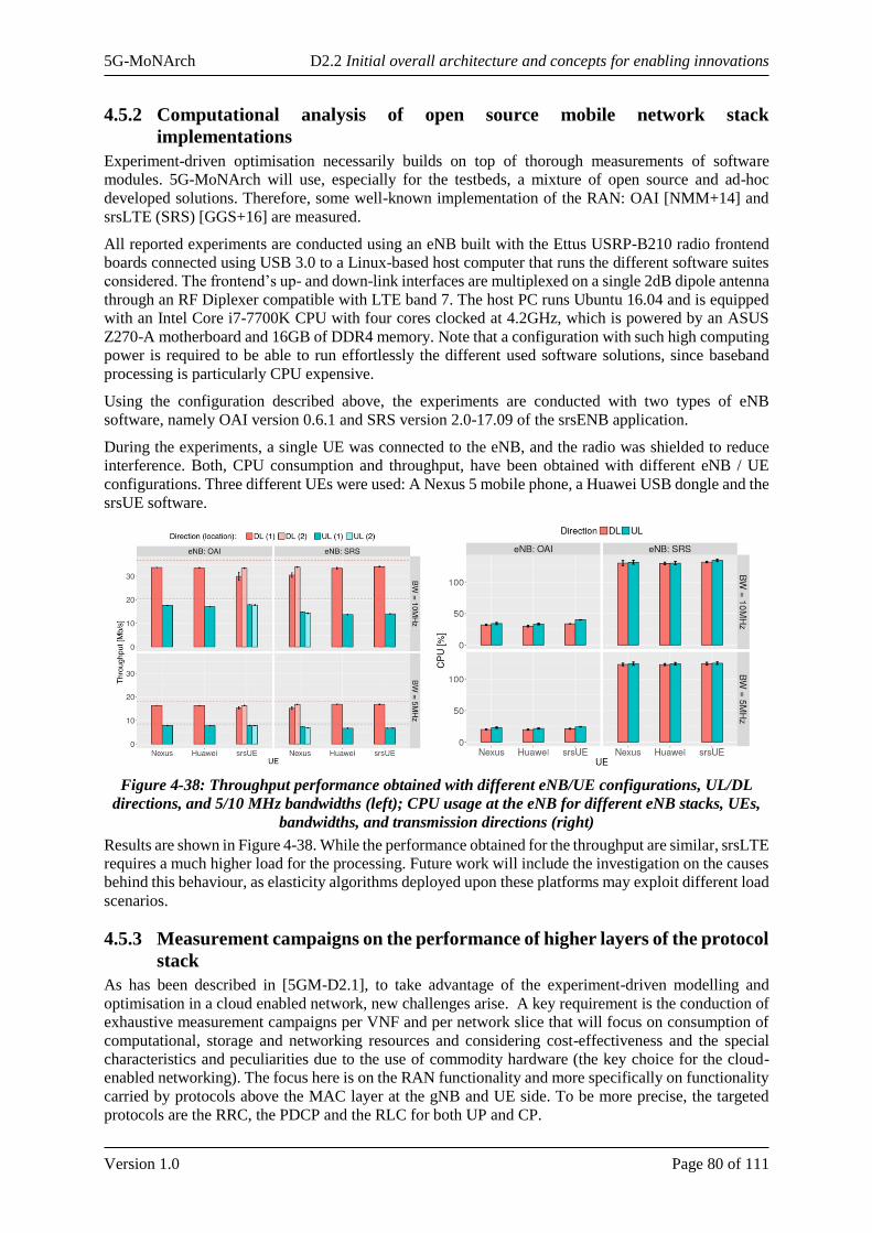
5G-MoNArch D2.2 Initial overall architecture and concepts for enabling innovations
Version 1.0 Page 80 of 111
4.5.2 Computational analysis of open source mobile network stack
implementations
Experiment-driven optimisation necessarily builds on top of thorough measurements of software
modules. 5G-MoNArch will use, especially for the testbeds, a mixture of open source and ad-hoc
developed solutions. Therefore, some well-known implementation of the RAN: OAI [NMM+14] and
srsLTE (SRS) [GGS+16] are measured.
All reported experiments are conducted using an eNB built with the Ettus USRP-B210 radio frontend
boards connected using USB 3.0 to a Linux-based host computer that runs the different software suites
considered. The frontend’s up- and down-link interfaces are multiplexed on a single 2dB dipole antenna
through an RF Diplexer compatible with LTE band 7. The host PC runs Ubuntu 16.04 and is equipped
with an Intel Core i7-7700K CPU with four cores clocked at 4.2GHz, which is powered by an ASUS
Z270-A motherboard and 16GB of DDR4 memory. Note that a configuration with such high computing
power is required to be able to run effortlessly the different used software solutions, since baseband
processing is particularly CPU expensive.
Using the configuration described above, the experiments are conducted with two types of eNB
software, namely OAI version 0.6.1 and SRS version 2.0-17.09 of the srsENB application.
During the experiments, a single UE was connected to the eNB, and the radio was shielded to reduce
interference. Both, CPU consumption and throughput, have been obtained with different eNB / UE
configurations. Three different UEs were used: A Nexus 5 mobile phone, a Huawei USB dongle and the
srsUE software.
Figure 4-38: Throughput performance obtained with different eNB/UE configurations, UL/DL
directions, and 5/10 MHz bandwidths (left); CPU usage at the eNB for different eNB stacks, UEs,
bandwidths, and transmission directions (right)
Results are shown in Figure 4-38. While the performance obtained for the throughput are similar, srsLTE
requires a much higher load for the processing. Future work will include the investigation on the causes
behind this behaviour, as elasticity algorithms deployed upon these platforms may exploit different load
scenarios.
4.5.3 Measurement campaigns on the performance of higher layers of the protocol
stack
As has been described in [5GM-D2.1], to take advantage of the experiment-driven modelling and
optimisation in a cloud enabled network, new challenges arise. A key requirement is the conduction of
exhaustive measurement campaigns per VNF and per network slice that will focus on consumption of
computational, storage and networking resources and considering cost-effectiveness and the special
characteristics and peculiarities due to the use of commodity hardware (the key choice for the cloud-
enabled networking). The focus here is on the RAN functionality and more specifically on functionality
carried by protocols above the MAC layer at the gNB and UE side. To be more precise, the targeted
protocols are the RRC, the PDCP and the RLC for both UP and CP.
5G-MoNArch D2.2 Initial overall architecture and concepts for enabling innovations
Version 1.0 Page 81 of 111
The evaluation of such an approach can be based on the actual testbed implementations. Key target is
the quantification of the computational and memory resources (CPU/RAM load) that are consumed by
the higher layer protocols in the RAN protocol stack as well as to investigate the impact that a function
split at the RLC level can provide in terms of delay to a provided service.

5G-MoNArch D2.2 Initial overall architecture and concepts for enabling innovations
Version 1.0 Page 82 of 111
5 Architectural Extensibility and Customisation
This chapter details the identified innovation elements and network functionalities towards flexible
extensibility and customisation of both network slice functionality and network infrastructure. In a first
step, the chapter describes the general framework, where the 5G-MoNArch Network Slice Blueprint
concept is used to design network slices incorporating customised network functions. Subsequently, it
elaborates on the 5G-MoNArch Network Slice Allocation and Network Slice Congestion Control
concepts to demonstrate how a single common infrastructure can efficiently host multiple network slices
instances. Finally, the presented concepts are applied to the two 5G-MoNArch testbeds: For the Smart
Sea Port scenario, specific network functions for resilience and security extend ‘standard’ URLLC and
mMTC slices to be deployed on a common infrastructure in the city of Hamburg. For the Touristic City
scenario, specialised network functions for resource elasticity customise typical eMBB functionality
towards the requirements of interactive consumer applications.
General means for extensibility and customisation
In 5G-MoNArch, the Network Slice Blueprint concept is the major means to generate customised
network slices that are capable of realising the performance and functional requirements of the addressed
service.
GSMA recently started a work to standardise a Generic Slice Template (GST), every Network Slice can
be fully described by allocating values (or ranges of values) to each relevant attribute in the GST. GSMA
could also standardise some GST for specific vertical use cases.
5G-MoNArch foresees that starting from the GST, an Operator could make some more customisation
to build up some more specific basic templates that take into account its own specify network
deployment. In this way the Operator could have a catalogue of slice templates to start from when he
has to deploy a specific NSI to meet the customer specific requirements for a network slice.
For each vertical (e.g. eMBB, URLLC) the Operator starts from the specific GST for that vertical,
customise it according to the peculiarity of his network infrastructure and creates a catalogue. When a
customer asks for a communication service the Operator picks the most adequate template from the
catalogue and extend and customise it according to the customer specific requirements.
This process, mostly automated, lead to the concrete definition of a NSI in terms of specific
configurations that are used by the M&O layer to deploy the NSI. This concrete definition of the specific
NSI requested by the customers, with specific extensions and customisation, is the 5G-MoNArch
Network Slice Blueprint.
Figure 5-1: 5G-MoNArch network slice blueprint for slice extensibility and customisation
5.1.1 5G-MoNArch network slice blueprint concept
The 5G-MoNArch Network Slice Blueprint defines the Network Slice Instance in terms of network
functions, their interconnection and configuration according to a specific service request. The chosen
approach to define 5G-MoNArch Slice Blueprint is to refer and enhance what is already defined by
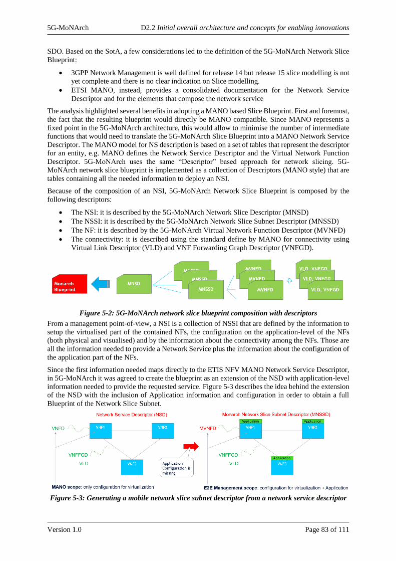
5G-MoNArch D2.2 Initial overall architecture and concepts for enabling innovations
Version 1.0 Page 83 of 111
SDO. Based on the SotA, a few considerations led to the definition of the 5G-MoNArch Network Slice
Blueprint:
• 3GPP Network Management is well defined for release 14 but release 15 slice modelling is not
yet complete and there is no clear indication on Slice modelling.
• ETSI MANO, instead, provides a consolidated documentation for the Network Service
Descriptor and for the elements that compose the network service
The analysis highlighted several benefits in adopting a MANO based Slice Blueprint. First and foremost,
the fact that the resulting blueprint would directly be MANO compatible. Since MANO represents a
fixed point in the 5G-MoNArch architecture, this would allow to minimise the number of intermediate
functions that would need to translate the 5G-MoNArch Slice Blueprint into a MANO Network Service
Descriptor. The MANO model for NS description is based on a set of tables that represent the descriptor
for an entity, e.g. MANO defines the Network Service Descriptor and the Virtual Network Function
Descriptor. 5G-MoNArch uses the same “Descriptor” based approach for network slicing. 5G-
MoNArch network slice blueprint is implemented as a collection of Descriptors (MANO style) that are
tables containing all the needed information to deploy an NSI.
Because of the composition of an NSI, 5G-MoNArch Network Slice Blueprint is composed by the
following descriptors:
• The NSI: it is described by the 5G-MoNArch Network Slice Descriptor (MNSD)
• The NSSI: it is described by the 5G-MoNArch Network Slice Subnet Descriptor (MNSSD)
• The NF: it is described by the 5G-MoNArch Virtual Network Function Descriptor (MVNFD)
• The connectivity: it is described using the standard define by MANO for connectivity using
Virtual Link Descriptor (VLD) and VNF Forwarding Graph Descriptor (VNFGD).
Figure 5-2: 5G-MoNArch network slice blueprint composition with descriptors
From a management point-of-view, a NSI is a collection of NSSI that are defined by the information to
setup the virtualised part of the contained NFs, the configuration on the application-level of the NFs
(both physical and visualised) and by the information about the connectivity among the NFs. Those are
all the information needed to provide a Network Service plus the information about the configuration of
the application part of the NFs.
Since the first information needed maps directly to the ETIS NFV MANO Network Service Descriptor,
in 5G-MoNArch it was agreed to create the blueprint as an extension of the NSD with application-level
information needed to provide the requested service. Figure 5-3 describes the idea behind the extension
of the NSD with the inclusion of Application information and configuration in order to obtain a full
Blueprint of the Network Slice Subnet.
Figure 5-3: Generating a mobile network slice subnet descriptor from a network service descriptor
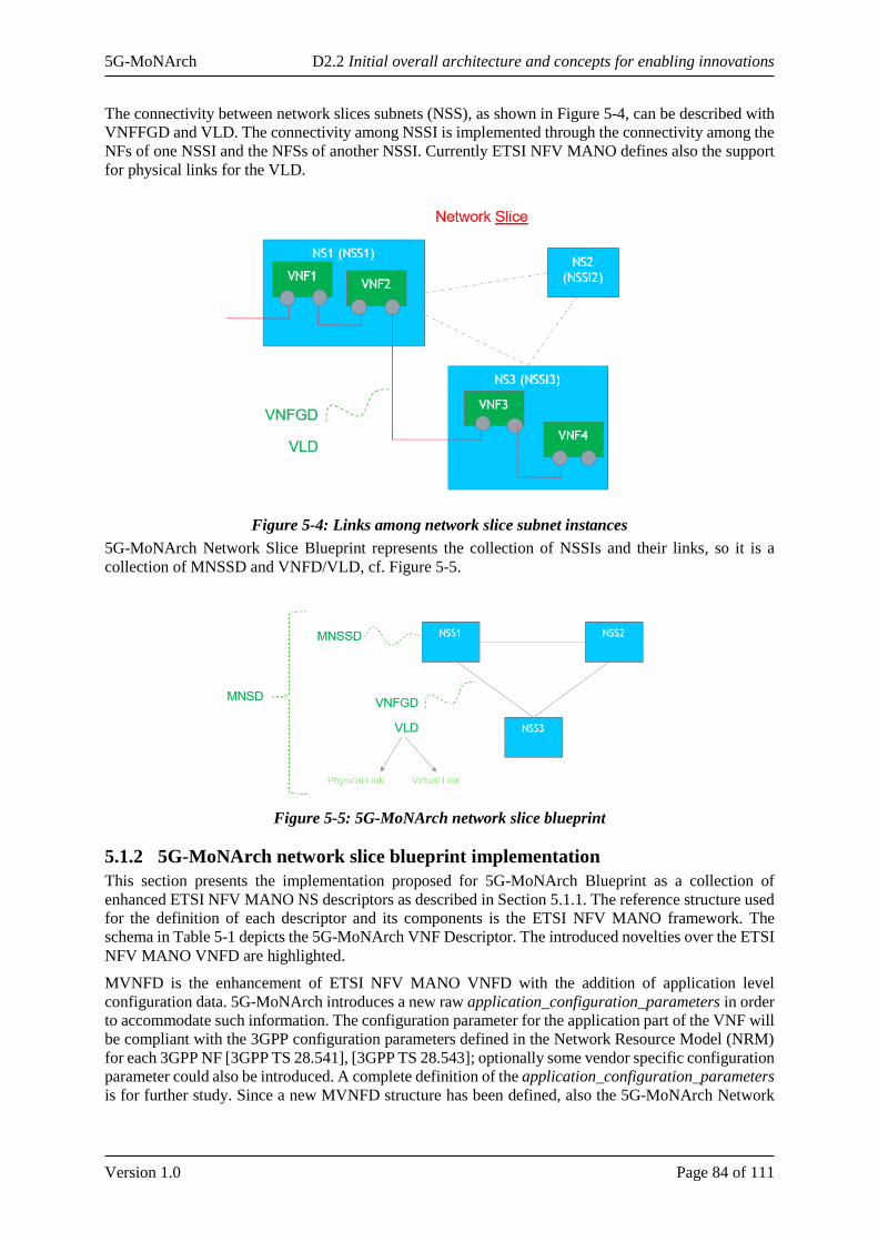
5G-MoNArch D2.2 Initial overall architecture and concepts for enabling innovations
Version 1.0 Page 84 of 111
The connectivity between network slices subnets (NSS), as shown in Figure 5-4, can be described with
VNFFGD and VLD. The connectivity among NSSI is implemented through the connectivity among the
NFs of one NSSI and the NFSs of another NSSI. Currently ETSI NFV MANO defines also the support
for physical links for the VLD.
Figure 5-4: Links among network slice subnet instances
5G-MoNArch Network Slice Blueprint represents the collection of NSSIs and their links, so it is a
collection of MNSSD and VNFD/VLD, cf. Figure 5-5.
Figure 5-5: 5G-MoNArch network slice blueprint
5.1.2 5G-MoNArch network slice blueprint implementation
This section presents the implementation proposed for 5G-MoNArch Blueprint as a collection of
enhanced ETSI NFV MANO NS descriptors as described in Section 5.1.1. The reference structure used
for the definition of each descriptor and its components is the ETSI NFV MANO framework. The
schema in Table 5-1 depicts the 5G-MoNArch VNF Descriptor. The introduced novelties over the ETSI
NFV MANO VNFD are highlighted.
MVNFD is the enhancement of ETSI NFV MANO VNFD with the addition of application level
configuration data. 5G-MoNArch introduces a new raw application_configuration_parameters in order
to accommodate such information. The configuration parameter for the application part of the VNF will
be compliant with the 3GPP configuration parameters defined in the Network Resource Model (NRM)
for each 3GPP NF [3GPP TS 28.541], [3GPP TS 28.543]; optionally some vendor specific configuration
parameter could also be introduced. A complete definition of the application_configuration_parameters
is for further study. Since a new MVNFD structure has been defined, also the 5G-MoNArch Network
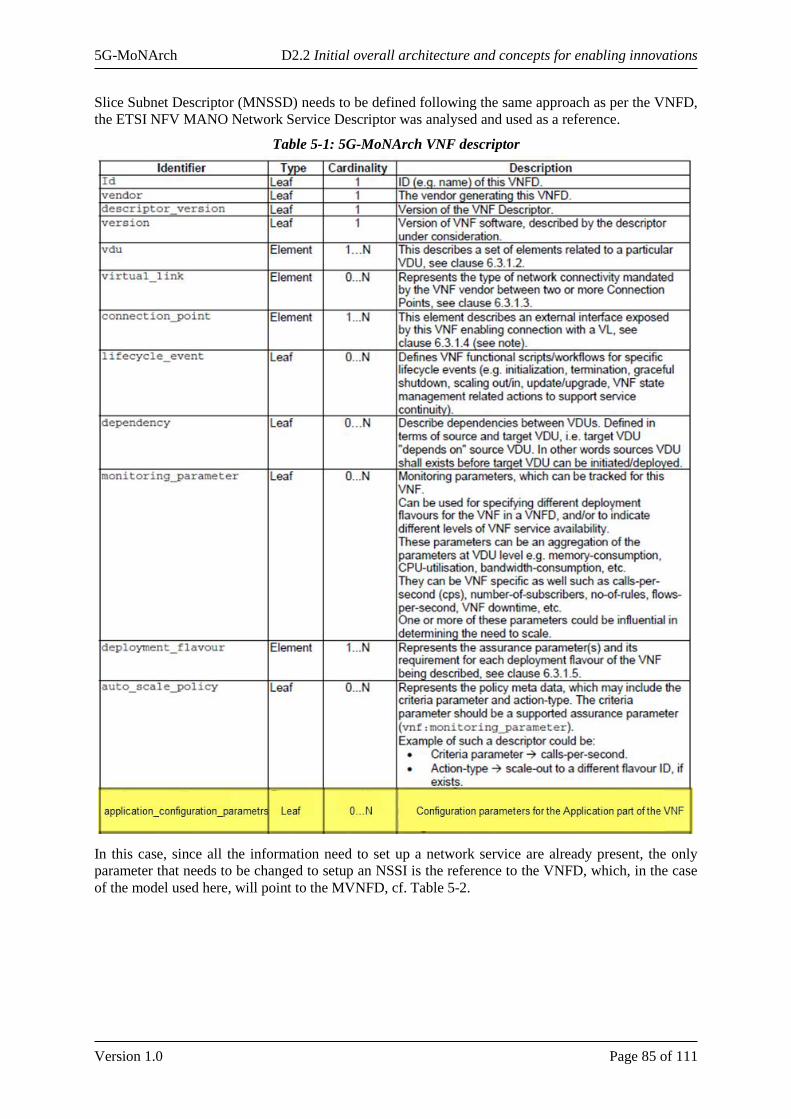
5G-MoNArch D2.2 Initial overall architecture and concepts for enabling innovations
Version 1.0 Page 85 of 111
Slice Subnet Descriptor (MNSSD) needs to be defined following the same approach as per the VNFD,
the ETSI NFV MANO Network Service Descriptor was analysed and used as a reference.
Table 5-1: 5G-MoNArch VNF descriptor
In this case, since all the information need to set up a network service are already present, the only
parameter that needs to be changed to setup an NSSI is the reference to the VNFD, which, in the case
of the model used here, will point to the MVNFD, cf. Table 5-2.
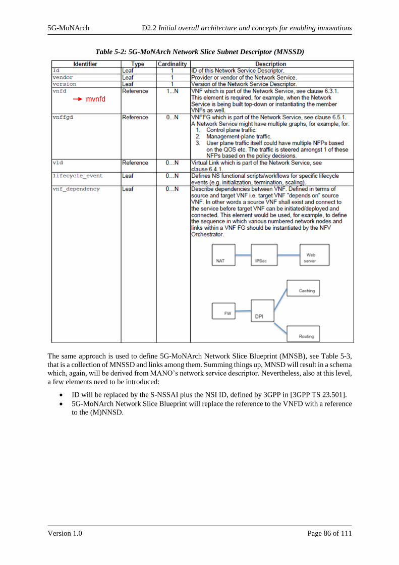
5G-MoNArch D2.2 Initial overall architecture and concepts for enabling innovations
Version 1.0 Page 86 of 111
Table 5-2: 5G-MoNArch Network Slice Subnet Descriptor (MNSSD)
The same approach is used to define 5G-MoNArch Network Slice Blueprint (MNSB), see Table 5-3,
that is a collection of MNSSD and links among them. Summing things up, MNSD will result in a schema
which, again, will be derived from MANO’s network service descriptor. Nevertheless, also at this level,
a few elements need to be introduced:
• ID will be replaced by the S-NSSAI plus the NSI ID, defined by 3GPP in [3GPP TS 23.501].
• 5G-MoNArch Network Slice Blueprint will replace the reference to the VNFD with a reference
to the (M)NNSD.
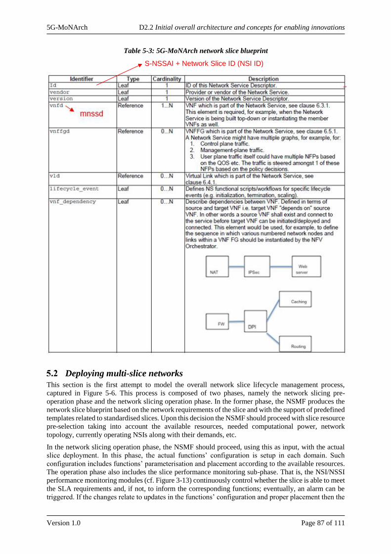
5G-MoNArch D2.2 Initial overall architecture and concepts for enabling innovations
Version 1.0 Page 87 of 111
Table 5-3: 5G-MoNArch network slice blueprint
Deploying multi-slice networks
This section is the first attempt to model the overall network slice lifecycle management process,
captured in Figure 5-6. This process is composed of two phases, namely the network slicing pre-
operation phase and the network slicing operation phase. In the former phase, the NSMF produces the
network slice blueprint based on the network requirements of the slice and with the support of predefined
templates related to standardised slices. Upon this decision the NSMF should proceed with slice resource
pre-selection taking into account the available resources, needed computational power, network
topology, currently operating NSIs along with their demands, etc.
In the network slicing operation phase, the NSMF should proceed, using this as input, with the actual
slice deployment. In this phase, the actual functions’ configuration is setup in each domain. Such
configuration includes functions’ parameterisation and placement according to the available resources.
The operation phase also includes the slice performance monitoring sub-phase. That is, the NSI/NSSI
performance monitoring modules (cf. Figure 3-13) continuously control whether the slice is able to meet
the SLA requirements and, if not, to inform the corresponding functions; eventually, an alarm can be
triggered. If the changes relate to updates in the functions’ configuration and proper placement then the
S-NSSAI + Network Slice ID (NSI ID)
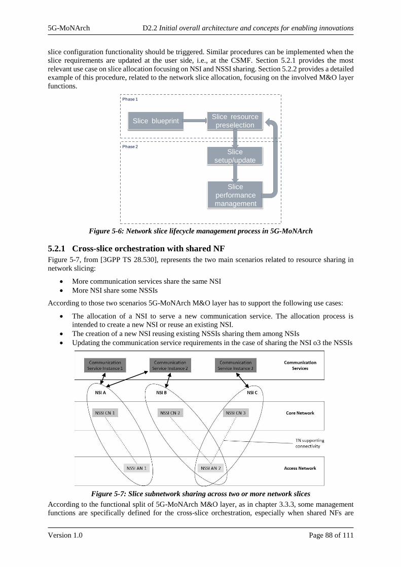
5G-MoNArch D2.2 Initial overall architecture and concepts for enabling innovations
Version 1.0 Page 88 of 111
slice configuration functionality should be triggered. Similar procedures can be implemented when the
slice requirements are updated at the user side, i.e., at the CSMF. Section 5.2.1 provides the most
relevant use case on slice allocation focusing on NSI and NSSI sharing. Section 5.2.2 provides a detailed
example of this procedure, related to the network slice allocation, focusing on the involved M&O layer
functions.
Figure 5-6: Network slice lifecycle management process in 5G-MoNArch
5.2.1 Cross-slice orchestration with shared NF
Figure 5-7, from [3GPP TS 28.530], represents the two main scenarios related to resource sharing in
network slicing:
• More communication services share the same NSI
• More NSI share some NSSIs
According to those two scenarios 5G-MoNArch M&O layer has to support the following use cases:
• The allocation of a NSI to serve a new communication service. The allocation process is
intended to create a new NSI or reuse an existing NSI.
• The creation of a new NSI reusing existing NSSIs sharing them among NSIs
• Updating the communication service requirements in the case of sharing the NSI o3 the NSSIs
Figure 5-7: Slice subnetwork sharing across two or more network slices
According to the functional split of 5G-MoNArch M&O layer, as in chapter 3.3.3, some management
functions are specifically defined for the cross-slice orchestration, especially when shared NFs are
Slice blueprintSlice resource
preselection
Slice
setup/update
Slice
performance
management
Phase 1
Phase 2
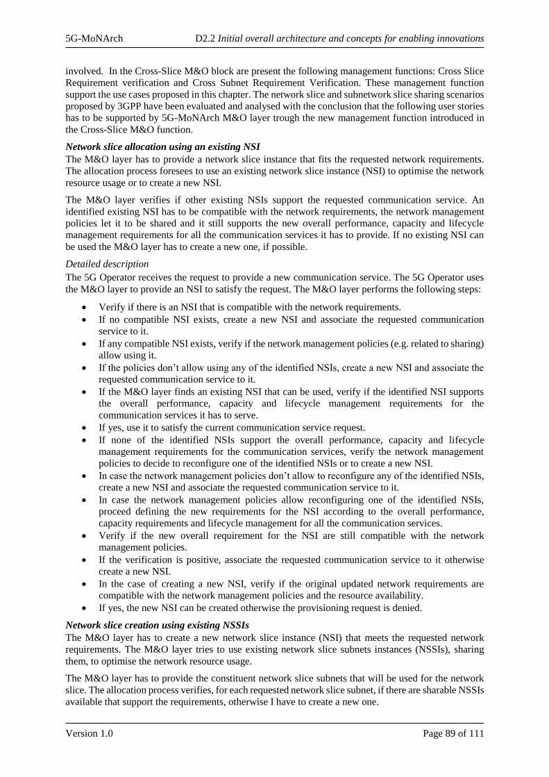
5G-MoNArch D2.2 Initial overall architecture and concepts for enabling innovations
Version 1.0 Page 89 of 111
involved. In the Cross-Slice M&O block are present the following management functions: Cross Slice
Requirement verification and Cross Subnet Requirement Verification. These management function
support the use cases proposed in this chapter. The network slice and subnetwork slice sharing scenarios
proposed by 3GPP have been evaluated and analysed with the conclusion that the following user stories
has to be supported by 5G-MoNArch M&O layer trough the new management function introduced in
the Cross-Slice M&O function.
Network slice allocation using an existing NSI
The M&O layer has to provide a network slice instance that fits the requested network requirements.
The allocation process foresees to use an existing network slice instance (NSI) to optimise the network
resource usage or to create a new NSI.
The M&O layer verifies if other existing NSIs support the requested communication service. An
identified existing NSI has to be compatible with the network requirements, the network management
policies let it to be shared and it still supports the new overall performance, capacity and lifecycle
management requirements for all the communication services it has to provide. If no existing NSI can
be used the M&O layer has to create a new one, if possible.
Detailed description
The 5G Operator receives the request to provide a new communication service. The 5G Operator uses
the M&O layer to provide an NSI to satisfy the request. The M&O layer performs the following steps:
• Verify if there is an NSI that is compatible with the network requirements.
• If no compatible NSI exists, create a new NSI and associate the requested communication
service to it.
• If any compatible NSI exists, verify if the network management policies (e.g. related to sharing)
allow using it.
• If the policies don’t allow using any of the identified NSIs, create a new NSI and associate the
requested communication service to it.
• If the M&O layer finds an existing NSI that can be used, verify if the identified NSI supports
the overall performance, capacity and lifecycle management requirements for the
communication services it has to serve.
• If yes, use it to satisfy the current communication service request.
• If none of the identified NSIs support the overall performance, capacity and lifecycle
management requirements for the communication services, verify the network management
policies to decide to reconfigure one of the identified NSIs or to create a new NSI.
• In case the network management policies don’t allow to reconfigure any of the identified NSIs,
create a new NSI and associate the requested communication service to it.
• In case the network management policies allow reconfiguring one of the identified NSIs,
proceed defining the new requirements for the NSI according to the overall performance,
capacity requirements and lifecycle management for all the communication services.
• Verify if the new overall requirement for the NSI are still compatible with the network
management policies.
• If the verification is positive, associate the requested communication service to it otherwise
create a new NSI.
• In the case of creating a new NSI, verify if the original updated network requirements are
compatible with the network management policies and the resource availability.
• If yes, the new NSI can be created otherwise the provisioning request is denied.
Network slice creation using existing NSSIs
The M&O layer has to create a new network slice instance (NSI) that meets the requested network
requirements. The M&O layer tries to use existing network slice subnets instances (NSSIs), sharing
them, to optimise the network resource usage.
The M&O layer has to provide the constituent network slice subnets that will be used for the network
slice. The allocation process verifies, for each requested network slice subnet, if there are sharable NSSIs
available that support the requirements, otherwise I have to create a new one.
5G-MoNArch D2.2 Initial overall architecture and concepts for enabling innovations
Version 1.0 Page 90 of 111
Detailed description
The M&O layer has already identified that the requested communication service cannot rely on an
existing NSI, so it is proceeding to create a new NSI.
As part of a new NSI creation process, The M&O layer decomposes the network slice requirements into
network slice subnet requirements.
The M&O layer allocates the network slice subnets using existing NSSIs or creating new ones, if
possible. The M&O layer verifies if there are already deployed NSSIs that can be shared in terms of
network management policies and that are compatible in terms of requirements.
To provide each requested NSSI, the M&O layer performs the following steps:
• Verify if there is an NSSI that is compatible with the network subnet requirements.
• If there is no compatible NSSI, create a new NSSI.
• If there is a compatible NSSIs, verify if the network management policies (e.g. related to
sharing) let me use it.
• If the network management policies don’t allow me to use any of the identified NSSIs, create a
new NSSI.
• If any compatible NSSI exists, verify if it supports the overall performance, capacity and
lifecycle management requirements for all the NSIs it has to serve.
• If yes, use it to satisfy the current request for network slice subnet allocation.
• If none of the identified NSSIs supports the overall performance, capacity and lifecycle
management requirements requested by all the NSIs, verify the network management policies
(e.g. related to an NSSI maximum capacity) to decide if to reconfigure one of the identified
NSSIs or to create a new NSSI.
• In case the network management policies allow to reconfigure one of the identified NSSIs,
proceed defining the new requirements for the NSSI according to the overall performance,
lifecycle management and capacity requirements for all the NSIs it has to serve.
• Verify if these new overall requirements for the NSSI are still compatible with the network
management policies.
• If the verification is positive, reconfigure the NSSI, otherwise create a new NSSI.
• In the case of creating a new NSSI, verify if the original updated network requirements are
compatible with the network management policies and the resource availability.
• If yes, the new NSSI can be created otherwise the NSI allocation request is denied and,
consequently, the NSI creation request is denied.
Requirements update when the NSI is shared among services
The M&O layer has to modify a network slice instance (NSI) according to a request of network
requirements update.
The M&O layer verifies if the current NSI already supports the new requirements and if it still supports
the new overall performance, capacity and lifecycle management requirements for all the
communication services it has to provide. If needed and if it is possible accordingly to the network
management policies (e.g. related to an NSI maximum capacity), The M&O layer reconfigures the NSI,
otherwise the operator creates a new network slice instance to support the communication service.
Detailed description
The M&O layer receives the request to update the network requirements of a communication service
provided by an NSI.
The M&O layer performs the following steps:
• Verify if the current NSI is still compatible with the new network requirements
• If yes, verify if the new overall performance, capacity and lifecycle requirements for all the
communication services are still compatible with the NSI.
• If yes, use it to satisfy the current communication service request.
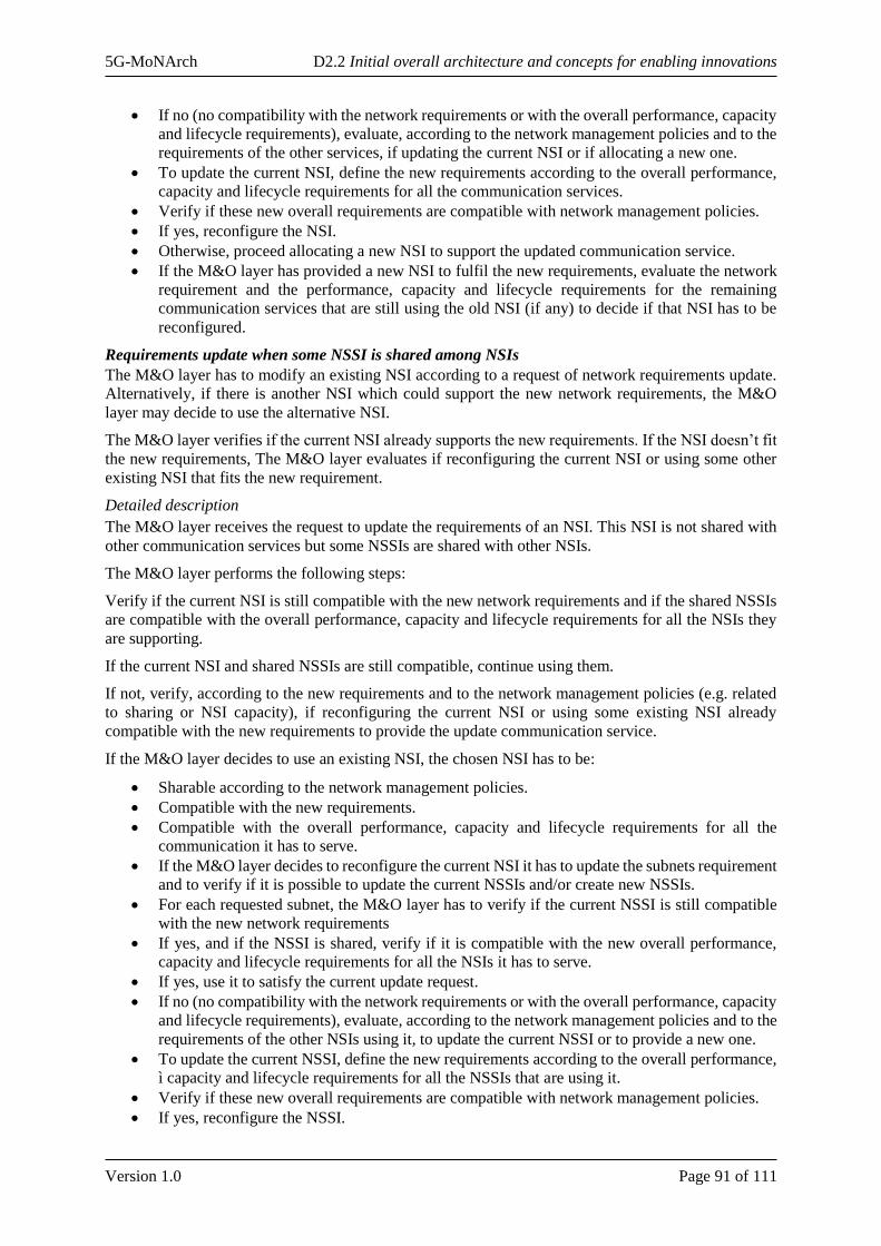
5G-MoNArch D2.2 Initial overall architecture and concepts for enabling innovations
Version 1.0 Page 91 of 111
• If no (no compatibility with the network requirements or with the overall performance, capacity
and lifecycle requirements), evaluate, according to the network management policies and to the
requirements of the other services, if updating the current NSI or if allocating a new one.
• To update the current NSI, define the new requirements according to the overall performance,
capacity and lifecycle requirements for all the communication services.
• Verify if these new overall requirements are compatible with network management policies.
• If yes, reconfigure the NSI.
• Otherwise, proceed allocating a new NSI to support the updated communication service.
• If the M&O layer has provided a new NSI to fulfil the new requirements, evaluate the network
requirement and the performance, capacity and lifecycle requirements for the remaining
communication services that are still using the old NSI (if any) to decide if that NSI has to be
reconfigured.
Requirements update when some NSSI is shared among NSIs
The M&O layer has to modify an existing NSI according to a request of network requirements update.
Alternatively, if there is another NSI which could support the new network requirements, the M&O
layer may decide to use the alternative NSI.
The M&O layer verifies if the current NSI already supports the new requirements. If the NSI doesn’t fit
the new requirements, The M&O layer evaluates if reconfiguring the current NSI or using some other
existing NSI that fits the new requirement.
Detailed description
The M&O layer receives the request to update the requirements of an NSI. This NSI is not shared with
other communication services but some NSSIs are shared with other NSIs.
The M&O layer performs the following steps:
Verify if the current NSI is still compatible with the new network requirements and if the shared NSSIs
are compatible with the overall performance, capacity and lifecycle requirements for all the NSIs they
are supporting.
If the current NSI and shared NSSIs are still compatible, continue using them.
If not, verify, according to the new requirements and to the network management policies (e.g. related
to sharing or NSI capacity), if reconfiguring the current NSI or using some existing NSI already
compatible with the new requirements to provide the update communication service.
If the M&O layer decides to use an existing NSI, the chosen NSI has to be:
• Sharable according to the network management policies.
• Compatible with the new requirements.
• Compatible with the overall performance, capacity and lifecycle requirements for all the
communication it has to serve.
• If the M&O layer decides to reconfigure the current NSI it has to update the subnets requirement
and to verify if it is possible to update the current NSSIs and/or create new NSSIs.
• For each requested subnet, the M&O layer has to verify if the current NSSI is still compatible
with the new network requirements
• If yes, and if the NSSI is shared, verify if it is compatible with the new overall performance,
capacity and lifecycle requirements for all the NSIs it has to serve.
• If yes, use it to satisfy the current update request.
• If no (no compatibility with the network requirements or with the overall performance, capacity
and lifecycle requirements), evaluate, according to the network management policies and to the
requirements of the other NSIs using it, to update the current NSSI or to provide a new one.
• To update the current NSSI, define the new requirements according to the overall performance,
ì capacity and lifecycle requirements for all the NSSIs that are using it.
• Verify if these new overall requirements are compatible with network management policies.
• If yes, reconfigure the NSSI.
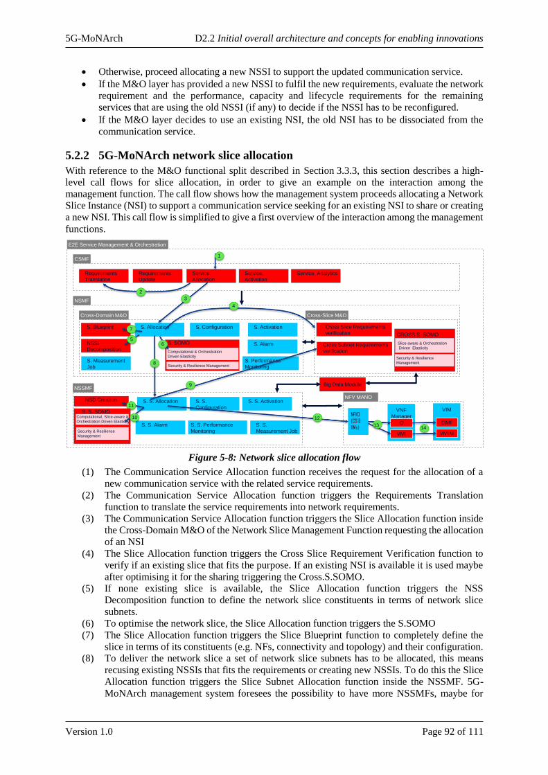
5G-MoNArch D2.2 Initial overall architecture and concepts for enabling innovations
Version 1.0 Page 92 of 111
• Otherwise, proceed allocating a new NSSI to support the updated communication service.
• If the M&O layer has provided a new NSSI to fulfil the new requirements, evaluate the network
requirement and the performance, capacity and lifecycle requirements for the remaining
services that are using the old NSSI (if any) to decide if the NSSI has to be reconfigured.
• If the M&O layer decides to use an existing NSI, the old NSI has to be dissociated from the
communication service.
5.2.2 5G-MoNArch network slice allocation
With reference to the M&O functional split described in Section 3.3.3, this section describes a high-
level call flows for slice allocation, in order to give an example on the interaction among the
management function. The call flow shows how the management system proceeds allocating a Network
Slice Instance (NSI) to support a communication service seeking for an existing NSI to share or creating
a new NSI. This call flow is simplified to give a first overview of the interaction among the management
functions.
Figure 5-8: Network slice allocation flow
(1) The Communication Service Allocation function receives the request for the allocation of a
new communication service with the related service requirements.
(2) The Communication Service Allocation function triggers the Requirements Translation
function to translate the service requirements into network requirements.
(3) The Communication Service Allocation function triggers the Slice Allocation function inside
the Cross-Domain M&O of the Network Slice Management Function requesting the allocation
of an NSI
(4) The Slice Allocation function triggers the Cross Slice Requirement Verification function to
verify if an existing slice that fits the purpose. If an existing NSI is available it is used maybe
after optimising it for the sharing triggering the Cross.S.SOMO.
(5) If none existing slice is available, the Slice Allocation function triggers the NSS
Decomposition function to define the network slice constituents in terms of network slice
subnets.
(6) To optimise the network slice, the Slice Allocation function triggers the S.SOMO
(7) The Slice Allocation function triggers the Slice Blueprint function to completely define the
slice in terms of its constituents (e.g. NFs, connectivity and topology) and their configuration.
(8) To deliver the network slice a set of network slice subnets has to be allocated, this means
recusing existing NSSIs that fits the requirements or creating new NSSIs. To do this the Slice
Allocation function triggers the Slice Subnet Allocation function inside the NSSMF. 5G-
MoNArch management system foresees the possibility to have more NSSMFs, maybe for
E2E Service Management & Orchestration
CSMF
NSMF
Cross-Domain M&O Cross-Slice M&O
NSSMF
S. Allocation S. Configuration S. Activation
S. S. Allocation S. S.
Configuration
S. S. Activation
S. Alarm
S. S. Alarm
Requirements
Translation
Requirements
Update
Service.
Allocation
Service.
Activation
Service. Analytics
S. Blueprint
NSSI
Decomposition
NSD Creation
Cross Slice Requirements
verification
Cross Subnet Requirements
verification
1
2
3
7
5
4
8
11
12
Big Data Module
NFV MANO
NFVO
(CS &
VMs)
VNF
Manager
VMI
CI13
VIM
VMIM
CIMF14
S. Performance
Monitoring
S. SOMO
Computational & Orchestration
Driven Elasticity
6
CROSS S. SOMO
Slice-aware & Orchestration
Driven Elasticity
S. S. SOMOComputational, Slice-aware &
Orchestration Driven ElasticityS. S. Performance
Monitoring
S. S.
Measurement Job
S. Measurement
Job Security & Resilience Management
Security & Resilience
Management
Security & Resilience
Management
10
9
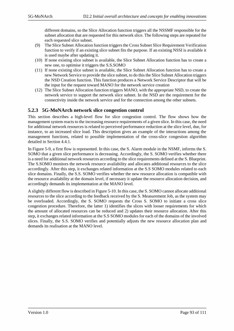
5G-MoNArch D2.2 Initial overall architecture and concepts for enabling innovations
Version 1.0 Page 93 of 111
different domains, so the Slice Allocation function triggers all the NSSMF responsible for the
subnet allocation that are requested for this network slice. The following steps are repeated for
each requested slice subnet.
(9) The Slice Subnet Allocation function triggers the Cross Subnet Slice Requirement Verification
function to verify if an existing slice subnet fits the purpose. If an existing NSSI is available it
is used maybe after updating it.
(10) If none existing slice subnet is available, the Slice Subnet Allocation function has to create a
new one, to optimise it triggers the S.S.SOMO
(11) If none existing slice subnet is available, the Slice Subnet Allocation function has to create a
new Network Service to provide the slice subnet, to do this the Slice Subnet Allocation triggers
the NSD Creation function. This function produces a Network Service Descriptor that will be
the input for the request toward MANO for the network service creation
(12) The Slice Subnet Allocation function triggers MANO, with the appropriate NSD, to create the
network service to support the network slice subnet. In the NSD are the requirement for the
connectivity inside the network service and for the connection among the other subnets.
5.2.3 5G-MoNArch network slice congestion control
This section describes a high-level flow for slice congestion control. The flow shows how the
management system reacts to the increasing resource requirements of a given slice. In this case, the need
for additional network resources is related to perceived performance reduction at the slice level, due, for
instance, to an increased slice load. This description gives an example of the interactions among the
management functions, related to possible implementation of the cross-slice congestion algorithm
detailed in Section 4.4.1.
In Figure 5-9, a first flow is represented. In this case, the S. Alarm module in the NSMF, informs the S.
SOMO that a given slice performance is decreasing. Accordingly, the S. SOMO verifies whether there
is a need for additional network resources according to the slice requirements defined at the S. Blueprint.
The S.SOMO monitors the network resource availability and allocates additional resources to the slice
accordingly. After this step, it exchanges related information at the S.S SOMO modules related to each
slice domains. Finally, the S.S. SOMO verifies whether the new resource allocation is compatible with
the resource availability at the domain level, if necessary it update the resource allocation decision, and
accordingly demands its implementation at the MANO level.
A slightly different flow is described in Figure 5-10. In this case, the S. SOMO cannot allocate additional
resources to the slice according to the feedback received by the S. Measurement Job, as the system may
be overloaded. Accordingly, the S. SOMO requests the Cross S. SOMO to initiate a cross slice
congestion procedure. Therefore, the latter 1) identifies the slices with looser requirements for which
the amount of allocated resources can be reduced and 2) updates their resource allocation. After this
step, it exchanges related information at the S.S SOMO modules for each of the domains of the involved
slices. Finally, the S.S. SOMO verifies and potentially adjusts the new resource allocation plan and
demands its realisation at the MANO level.
5G-MoNArch D2.2 Initial overall architecture and concepts for enabling innovations
Version 1.0 Page 94 of 111
Figure 5-9: Network slice congestion control flow
Figure 5-10: Cross-slice congestion control flow
Integration of functional innovations for 5G-MoNArch use cases
5.3.1 Resilience and security
5.3.1.1 Basic concepts and required architecture components
A network slice intended to support URLLC services needs to fulfil high resilience, reliability and
security requirements. Such specialised service requirements coming from the customer need to be
carefully translated into the resource-facing service description, e.g. by including in the slice template
the network functions and their corresponding configurations that can support the specified
requirements. Furthermore, the slice template need to contain the instructions for actual deployment,
management, orchestration and control of specialised NFs that will be executed by different functions
of 5G-MoNArch architecture, e.g. instructions on LCM of specialised VNFs that will be executed by
VNFM.
E2E Service Management & Orchestration
CSMF
NSMF
Cross-Domain M&O Cross-Slice M&O
NSSMF
S. Allocation S. Configuration S. Activation
S. S. Allocation S. S.
Configuration
S. S. Activation
S. Alarm
S. S. Alarm
Requirements
Translation
Requirements
Update
Service.
Allocation
Service.
Activation
Service. Analytics
S. Blueprint
NSSI
Decomposition
NSD Creation
Cross Slice Requirements
verification
Cross Subnet Requirements
verification
12
7
Big Data Module
NFV MANO
NFVO
(CS &
VMs)
VNF
Manager
VMI
CI
VIM
VMIM
CIMF
S. Performance
Monitoring
S. SOMO
Computational & Orchestration
Driven Elasticity
CROSS S. SOMO
Slice-aware & Orchestration
Driven Elasticity
S. S. SOMOComputational, Slice-aware &
Orchestration Driven ElasticityS. S. Performance
Monitoring
S. S.
Measurement Job
S. Measurement
Job Security & Resilience Management
Security & Resilience
Management
Security & Resilience
Management
3
4
6
5
E2E Service Management & Orchestration
CSMF
NSMF
Cross-Domain M&O Cross-Slice M&O
NSSMF
S. Allocation S. Configuration S. Activation
S. S. Allocation S. S.
Configuration
S. S. Activation
S. Alarm
S. S. Alarm
Requirements
Translation
Requirements
Update
Service.
Allocation
Service.
Activation
Service. Analytics
S. Blueprint
NSSI
Decomposition
NSD Creation
Cross Slice Requirements
verification
Cross Subnet Requirements
verification
12
8
Big Data Module
NFV MANO
NFVO
(CS &
VMs)
VNF
Manager
VMI
CI
VIM
VMIM
CIMF
S. Performance
Monitoring
S. SOMO
Computational & Orchestration
Driven Elasticity
CROSS S. SOMO
Slice-aware & Orchestration
Driven Elasticity
S. S. SOMOComputational, Slice-aware &
Orchestration Driven ElasticityS. S. Performance
Monitoring
S. S.
Measurement Job
S. Measurement
Job Security & Resilience Management
Security & Resilience
Management
Security & Resilience
Management
3
4
5
6
7
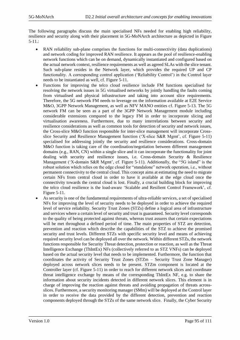
5G-MoNArch D2.2 Initial overall architecture and concepts for enabling innovations
Version 1.0 Page 95 of 111
The following paragraphs discuss the main specialised NFs needed for enabling high reliability,
resilience and security along with their placement in 5G-MoNArch architecture as depicted in Figure
5-11.:
• RAN reliability sub-plane comprises the functions for multi-connectivity (data duplications)
and network coding for improved RAN resilience. It appears as the pool of resilience-enabling
network functions which can be on demand, dynamically instantiated and configured based on
the actual network context, resilience requirements as well as agreed SLAs with the slice tenant.
Such sub-plane resides in the Network layer, which provides the required UP and CP
functionality. A corresponding control application (‘Reliability Control’) in the Control layer
needs to be instantiated as well, cf. Figure 5-11.
• Functions for improving the telco cloud resilience include FM functions specialised for
resolving the network issues in 5G virtualised networks by jointly handling the faults coming
from virtualised and physical infrastructure and taking into account slice requirements.
Therefore, the 5G network FM needs to leverage on the information available at E2E Service
M&O, 3GPP Network Management, as well as NFV MANO entities cf. Figure 5-13. The 5G
network FM can be seen as a part of the 3GPP Network Management module including
considerable extensions compared to the legacy FM in order to incorporate slicing and
virtualisation awareness. Furthermore, due to many interrelations between security and
resilience considerations as well as common tools for detection of security and network issues,
the Cross-slice M&O function responsible for inter-slice management will incorporate Cross-
slice Security and Resilience Management function (‘X-slice S&R Mgmt’, cf. Figure 5-11)
specialised for addressing jointly the security and resilience considerations. Cross-domain
M&O function is taking care of the coordination/negotiation between different management
domains (e.g., RAN, CN) within a single slice and it can incorporate the functionality for joint
dealing with security and resilience issues, i.e. Cross-domain Security & Resilience
Management (‘X-domain S&R Mgmt’, cf. Figure 5-11). Additionally, the “5G island” is the
robust solution which relies on the edge cloud for “standalone” network operation, i.e., without
permanent connectivity to the central cloud. This concept aims at estimating the need to migrate
certain NFs from central cloud in order to have it available at the edge cloud once the
connectivity towards the central cloud is lost. Finally, a crucial building block for improving
the telco cloud resilience is the load-aware ‘Scalable and Resilient Control Framework’, cf.
Figure 5-11.
• As security is one of the fundamental requirements of ultra-reliable services, a set of specialised
NFs for improving the level of security needs to be deployed in order to achieve the required
level of service reliability. Security Trust Zones (STZs) define a logical area of infrastructure
and services where a certain level of security and trust is guaranteed. Security level corresponds
to the quality of being protected against threats, whereas trust assures that certain expectations
will be met throughout a defined period of time. The main properties of STZ are detection,
prevention and reaction which describe the capabilities of the STZ to achieve the promised
security and trust levels. Different STZs with specific security level and means of achieving
required security level can be deployed all over the network. Within different STZs, the network
functions responsible for Security Threat detection, protection or reaction, as well as the Threat
Intelligence Exchange (ThIntEx) NFs (collectively referred to as STZ VNFs) can be deployed
based on the actual security level that needs to be implemented. Furthermore, the function that
coordinates the activity of Security Trust Zones (STZm – Security Trust Zone Manager)
deployed across network slices needs to be present. STZm component is located at the
Controller layer (cf. Figure 5-11) in order to reach for different network slices and coordinate
threat intelligence exchange by means of the corresponding ThIntEx NF, e.g. to share the
information about security incidents detected in different network slices. This element is in
charge of improving the reaction against threats and avoiding propagation of threats across-
slices. Furthermore, a security monitoring manager (SMm) will be deployed at the Control layer
in order to receive the data provided by the different detection, prevention and reaction
components deployed through the STZs of the same network slice. Finally, the Cyber Security
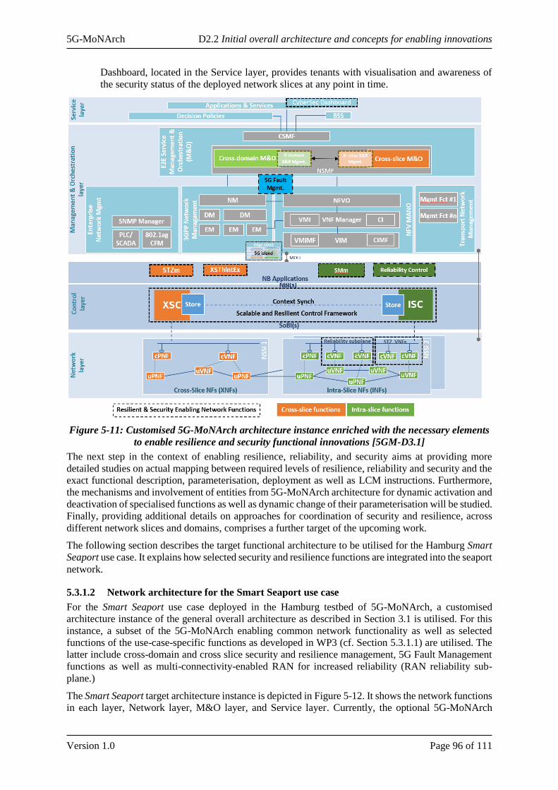
5G-MoNArch D2.2 Initial overall architecture and concepts for enabling innovations
Version 1.0 Page 96 of 111
Dashboard, located in the Service layer, provides tenants with visualisation and awareness of
the security status of the deployed network slices at any point in time.
Figure 5-11: Customised 5G-MoNArch architecture instance enriched with the necessary elements
to enable resilience and security functional innovations [5GM-D3.1]
The next step in the context of enabling resilience, reliability, and security aims at providing more
detailed studies on actual mapping between required levels of resilience, reliability and security and the
exact functional description, parameterisation, deployment as well as LCM instructions. Furthermore,
the mechanisms and involvement of entities from 5G-MoNArch architecture for dynamic activation and
deactivation of specialised functions as well as dynamic change of their parameterisation will be studied.
Finally, providing additional details on approaches for coordination of security and resilience, across
different network slices and domains, comprises a further target of the upcoming work.
The following section describes the target functional architecture to be utilised for the Hamburg Smart
Seaport use case. It explains how selected security and resilience functions are integrated into the seaport
network.
5.3.1.2 Network architecture for the Smart Seaport use case
For the Smart Seaport use case deployed in the Hamburg testbed of 5G-MoNArch, a customised
architecture instance of the general overall architecture as described in Section 3.1 is utilised. For this
instance, a subset of the 5G-MoNArch enabling common network functionality as well as selected
functions of the use-case-specific functions as developed in WP3 (cf. Section 5.3.1.1) are utilised. The
latter include cross-domain and cross slice security and resilience management, 5G Fault Management
functions as well as multi-connectivity-enabled RAN for increased reliability (RAN reliability sub-
plane.)
The Smart Seaport target architecture instance is depicted in Figure 5-12. It shows the network functions
in each layer, Network layer, M&O layer, and Service layer. Currently, the optional 5G-MoNArch

5G-MoNArch D2.2 Initial overall architecture and concepts for enabling innovations
Version 1.0 Page 97 of 111
control layer is not foreseen to be part of the Smart Seaport testbed. The network functions are
distributed across four locations in Hamburg and Nuremberg. In Hamburg, there are the Deutsche
Telekom (DT) Data Centre, the Hamburg Port Authority Data Centre (and private networks), and the
TV Tower hosting the base station. In Nuremberg, one of the central office Data Centres (‘central cloud’)
of DT is hosted. The four locations are depicted in yellow in Figure 5-12.
Figure 5-12: Targeted functional architecture for the Smart Seaport use case
In the Network layer, the testbed implements three network slices, enhanced Mobile Broadband (eMBB)
communication, Ultra-Reliable Low-Latency Communication (URLLC), and massive Machine-Type
Communication (mMTC) delivering the Augmented Reality (AR), Intelligent Transport Systems (ITS),
and Environmental Sensing use cases, respectively. They have the following deployment characteristics:
eMBB network slice: The eMBB network slice is utilised to carry the AR traffic (e.g., augmented
maintenance for HPA service staff) as well as providing eMBB services like Internet access or video
streaming to cruise ship tourists. In the Radio Access Network (RAN), the slice uses the common PHY
and MAC layers of the testbed radio infrastructure. SDAP, PDCP, and RLC layers are slice-specific due
to customisations reflecting service requirements. Further, RRC is common for all deployed slices. In
the control plane (CP), the AMF is shared with other network slices, while PCF, UDM, and SMF are
dedicated to the eMBB slice. Core network user plane (UP) function(s) are dedicated and therefore
service-specific. Besides AMF, all core network functions of the eMBB slice (from CP and UP) run in
DT’s central cloud data centre in Nuremberg, one of DT’s central office sites. Further, the AR
applications (and other eMBB-like applications) in the Data Network that process the incoming user
data are also hosted in Nuremberg.
URLLC network slice: The URLLC network slice is utilised for ITS applications in the seaport area, in
particular for traffic light control. Similar to the eMBB slice, the URLLC slice uses the common RRC
and lower radio layers (MAC and PHY) and service-specific upper radio layers (RLC, PDCP, SDAP)
in the RAN. One such service-specific customisation comprises the WP3 reliability sub-plane for multi-
connectivity, thus increasing reliability in the radio network. In the core network, AMF is shared with
all three deployed slices, while SMF, PCF, and UDM are shared among the slices deployed in the local
edge cloud (DT Data Centre, Hamburg), i.e., URLLC slice and mMTC slice. An alternative deployment
option would comprise separate PCFs for each of the two slices. Further details of PCF selection can be

5G-MoNArch D2.2 Initial overall architecture and concepts for enabling innovations
Version 1.0 Page 98 of 111
found in clause 6.3.7.1 of [3GPP TS 23.501]. The core network UP uses a dedicated and customised
UPF instance. Due to latency requirements for traffic light control, all network functionality in CP and
UP is deployed locally. Therefore, also the ITS Data applications in the Data Network are operated in
the local HPA Data Centre in Hamburg.
mMTC network slice: The mMTC slice is used to carry traffic from environment sensors deployed in
the Hamburg seaport, particularly from the barges patrolling through the seaport. The slice has the same
setup as the URLLC slice in terms of deployment of network (CP and UP, RAN and core network) and
application functions. Nevertheless, upper layer radio functions (RLC, PDCP, SDAP) and core network
UPF are realised as dedicated instances with customised behaviour.
The Management & Orchestration layer comprises DT’s functionalities for managing public land mobile
networks (PLMN), particularly Element Management (EM) functions and novel advanced 5G Fault
Management functions as developed in WP3. For the virtualisation management and orchestration
(MANO), the Hamburg seaport testbed utilises a VM-based virtualisation approach. The deployment
uses a streamlined ETSI NFV MANO architecture, i.e., VIM and an NFV lifecycle management
component integrating NFV Orchestrator and VNF Manager. Nevertheless, in general, container-based
solutions could be incorporated. For e2e M&O, NSMF and CSMF incorporate according monitoring as
well as fault and slice lifecycle management functions. From WP3, cross-domain and cross-slice
security and resilience management functions are incorporated into NSMF. A lightweight CSMF
implementation provides mediation capabilities between NSMF and the Service layer. Beyond these
M&O layer functions operated by DT in their Hamburg Data Centre, the deployment comprises the
management functions for HPA’s private networks, namely SNMP Managers and 802.1ag Connectivity
Fault Management running in HPA Data Centre in Hamburg. The latter functions manage the largely
wireline network infrastructure of HPA which is also used to connect the UPs of the local network slices
with the HPA Data Centre. More specifically, as depicted in Figure 5-5, the ITS and Environmental
Monitoring/Sensor Data applications run in the HPA Data Centre in Hamburg where the UP data
coming from the URLLC and mMTC slice, respectively, are forwarded to. Form the mobile network
perspective, these application fucntions belong to the Data Network outside the operator domain. Only
in case of the eMBB slice, the application (AR Data) is hosted in the DT Data Centre in Nuremberg.
Finally, each of the three applciations also has a management and control component residing in the
service layer, executed in the local HPA Data Centre. They interact with the CSMF to provide the
specific service requirements used to customise the slice instances and to receive latest performance and
configuration details about the network slice hosting the respective service.
5.3.2 Resource elasticity
5.3.2.1 Basic concepts and required architecture component
As discussed in Section 4.3.5, resource assignment in the network should avoid overprovisioning and
assign resources just where and when they are needed. This flexibility is referred to as resource elasticity,
which includes the ability (i) to scale resources according to the demand, and (ii) to gracefully scale the
network operation when insufficient resources are available.
Elasticity has been traditionally implemented in the context of communication resources, where the
network gracefully downgrades the quality for all users if its communication resources (e.g., spectrum,
radio link capacity) are insufficient. In the framework of a softwarised network, a new paradigm for
resource elasticity that comprises processing power, memory, and storage resources is needed. While
cloud frameworks typically aim at guaranteeing that the computational resources required by a function
are always there, in the orchestration environment considered here this may not be possible, since (i) the
timescales involved in RAN functions are much tighter than those considered in cloud solutions, which
cannot prevent outages at such short timescales, and (ii) cloud resources are typically limited at the edge,
preventing cloud solutions to exploit multiplexing gains. Adding more elasticity to the resource
consumption of NFs requires an understanding of the nature of the different resources and performance
trade-offs, leading to different dimensions of elasticity which are described next.
This section provides a set of ideas on how to provision resource elasticity, in particular the technical
challenges in the virtualised architecture of 5G systems that resource elasticity is meant to address, as
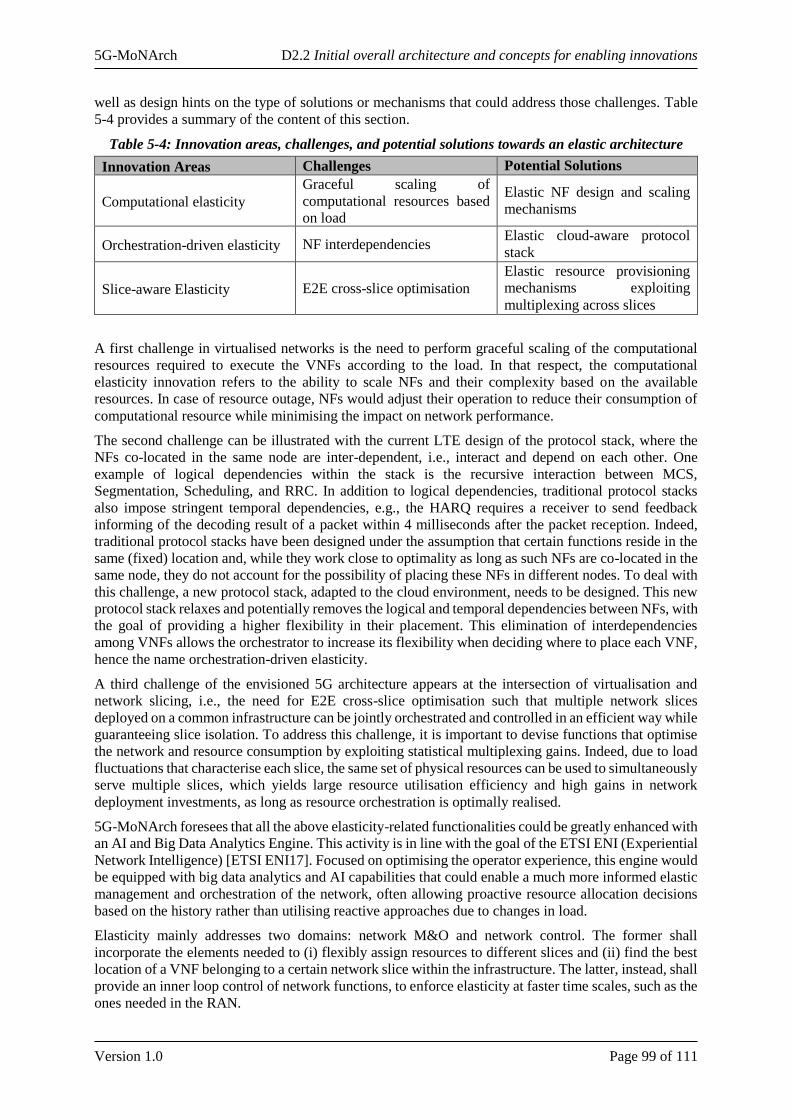
5G-MoNArch D2.2 Initial overall architecture and concepts for enabling innovations
Version 1.0 Page 99 of 111
well as design hints on the type of solutions or mechanisms that could address those challenges. Table
5-4 provides a summary of the content of this section.
Table 5-4: Innovation areas, challenges, and potential solutions towards an elastic architecture
Innovation Areas Challenges Potential Solutions
Computational elasticity
Graceful scaling of
computational resources based
on load
Elastic NF design and scaling
mechanisms
Orchestration-driven elasticity NF interdependencies Elastic cloud-aware protocol
stack
Slice-aware Elasticity E2E cross-slice optimisation
Elastic resource provisioning
mechanisms exploiting
multiplexing across slices
A first challenge in virtualised networks is the need to perform graceful scaling of the computational
resources required to execute the VNFs according to the load. In that respect, the computational
elasticity innovation refers to the ability to scale NFs and their complexity based on the available
resources. In case of resource outage, NFs would adjust their operation to reduce their consumption of
computational resource while minimising the impact on network performance.
The second challenge can be illustrated with the current LTE design of the protocol stack, where the
NFs co-located in the same node are inter-dependent, i.e., interact and depend on each other. One
example of logical dependencies within the stack is the recursive interaction between MCS,
Segmentation, Scheduling, and RRC. In addition to logical dependencies, traditional protocol stacks
also impose stringent temporal dependencies, e.g., the HARQ requires a receiver to send feedback
informing of the decoding result of a packet within 4 milliseconds after the packet reception. Indeed,
traditional protocol stacks have been designed under the assumption that certain functions reside in the
same (fixed) location and, while they work close to optimality as long as such NFs are co-located in the
same node, they do not account for the possibility of placing these NFs in different nodes. To deal with
this challenge, a new protocol stack, adapted to the cloud environment, needs to be designed. This new
protocol stack relaxes and potentially removes the logical and temporal dependencies between NFs, with
the goal of providing a higher flexibility in their placement. This elimination of interdependencies
among VNFs allows the orchestrator to increase its flexibility when deciding where to place each VNF,
hence the name orchestration-driven elasticity.
A third challenge of the envisioned 5G architecture appears at the intersection of virtualisation and
network slicing, i.e., the need for E2E cross-slice optimisation such that multiple network slices
deployed on a common infrastructure can be jointly orchestrated and controlled in an efficient way while
guaranteeing slice isolation. To address this challenge, it is important to devise functions that optimise
the network and resource consumption by exploiting statistical multiplexing gains. Indeed, due to load
fluctuations that characterise each slice, the same set of physical resources can be used to simultaneously
serve multiple slices, which yields large resource utilisation efficiency and high gains in network
deployment investments, as long as resource orchestration is optimally realised.
5G-MoNArch foresees that all the above elasticity-related functionalities could be greatly enhanced with
an AI and Big Data Analytics Engine. This activity is in line with the goal of the ETSI ENI (Experiential
Network Intelligence) [ETSI ENI17]. Focused on optimising the operator experience, this engine would
be equipped with big data analytics and AI capabilities that could enable a much more informed elastic
management and orchestration of the network, often allowing proactive resource allocation decisions
based on the history rather than utilising reactive approaches due to changes in load.
Elasticity mainly addresses two domains: network M&O and network control. The former shall
incorporate the elements needed to (i) flexibly assign resources to different slices and (ii) find the best
location of a VNF belonging to a certain network slice within the infrastructure. The latter, instead, shall
provide an inner loop control of network functions, to enforce elasticity at faster time scales, such as the
ones needed in the RAN.
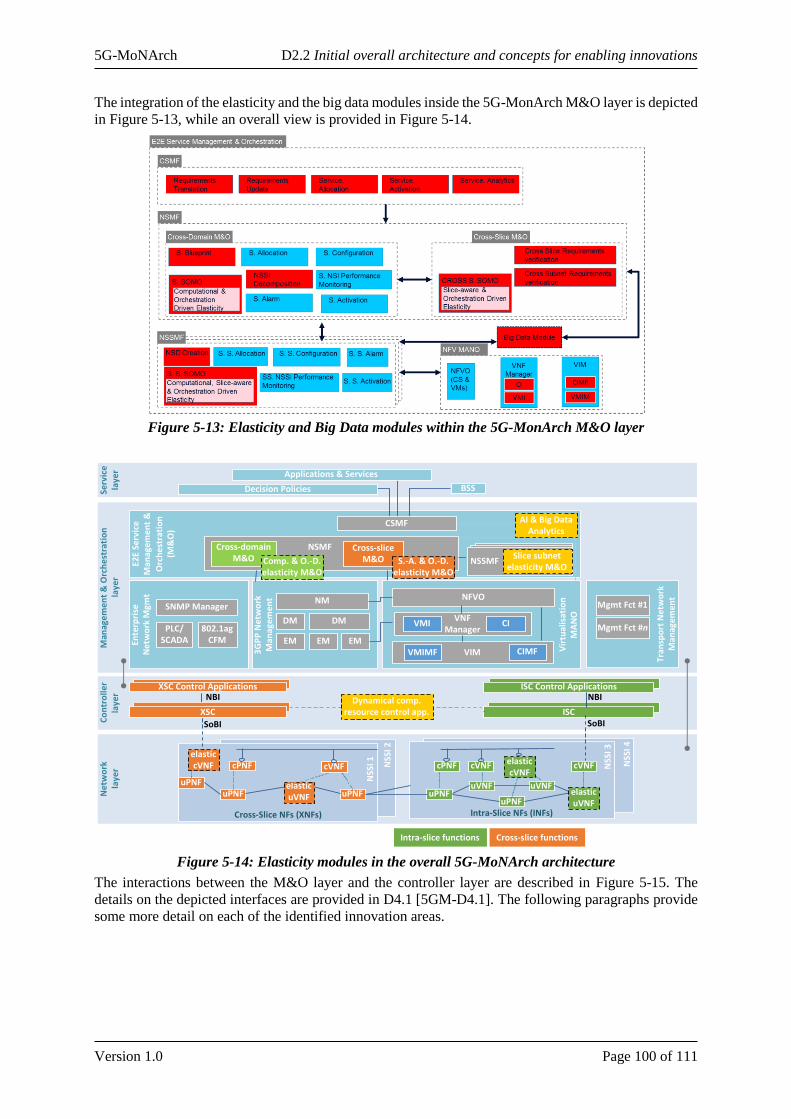
5G-MoNArch D2.2 Initial overall architecture and concepts for enabling innovations
Version 1.0 Page 100 of 111
The integration of the elasticity and the big data modules inside the 5G-MonArch M&O layer is depicted
in Figure 5-13, while an overall view is provided in Figure 5-14.
Figure 5-13: Elasticity and Big Data modules within the 5G-MonArch M&O layer
Figure 5-14: Elasticity modules in the overall 5G-MoNArch architecture
The interactions between the M&O layer and the controller layer are described in Figure 5-15. The
details on the depicted interfaces are provided in D4.1 [5GM-D4.1]. The following paragraphs provide
some more detail on each of the identified innovation areas.
Ne
two
rkla
yer
Cross-Slice NFs (XNFs)
Man
age
me
nt
& O
rch
est
rati
on
la
yer
E2E
Serv
ice
M
anag
eme
nt
&
Orc
he
stra
tio
n
(M&
O)
Serv
ice
laye
r
Decision Policies
Applications & Services
Intra-Slice NFs (INFs)
uPNFuVNF uVNF
uPNFuVNF
Cross-Slice NFs (XNFs)
uPNF uPNFuVNF
cVNF cPNFcPNF cVNF cVNF cVNF
Cross-slice functionsIntra-slice functions
BSS
3G
PP
Ne
two
rk
Man
agem
en
t
NSMFFFFFF
EM EM EMEnte
rpri
seN
etw
ork
Mgm
t
SNMP Manager
802.1ag CFM
PLC/ SCADA
CSMF
DM DM
NM
Tran
spo
rt N
etw
ork
M
anag
em
ent
Mgmt Fct #1
Mgmt Fct #n
Cross-slice M&O
Cross-domain M&O
NSS
I 2
NSS
I 3
NSS
I 4
NSS
I 1
uPNF
elastic cVNF
Co
ntr
oll
erla
yer
ISC Control Applications
ISC
NBI NBI
SoBI SoBI
XSC Control Applications
XSC
NSS
I 4
Vir
tual
isat
ion
MA
NO
VIMVMIMF CIMF
VNF Manager
VMI CI
NFVO
AI & Big Data Analytics
Comp. & O.-D. elasticity M&O
S.-A. & O.-D. elasticity M&O
Dynamical comp. resource control app.
NSSMFFFFFFFFFFFFFFFFNSSMFFFFFFFFFFFFFFFFNSSMFFFFFFFFFFFFFFFFFSlice subnet
elasticity M&O
elastic uVNF
elastic cVNF
elastic uVNF

5G-MoNArch D2.2 Initial overall architecture and concepts for enabling innovations
Version 1.0 Page 101 of 111
Figure 5-15: High-level interactions across elastic modules in the M&O and Controller layers
Computational elasticity
The goal of exploiting computational elasticity is to improve the utilisation efficiency of computational
resources by adapting the NF behaviour to the available resources without impacting performance
significantly. Furthermore, this dimension of elasticity addresses the notion of computational outage,
which implies that NFs may not have sufficient resources to perform their tasks within a given time. In
order to overcome computational outages, one potential solution is to design NFs that can gracefully
adjust the amount of computational resources consumed while keeping the highest possible level of
performance. RAN functions in particular have been typically designed to be robust only against
shortages on communication resources; hence, the target should be directed at making RAN functions
also robust to computational shortages by adapting their operation to the available computational
resources. An example could be a function that chooses to execute a less resource-demanding decoding
algorithm in case of resource outages, admitting a certain performance loss.
In addition, the scaling mechanisms, i.e., the modification of the amount of computational resources
allocated to such computationally elastic NFs may help in exploiting the elasticity of the system if they
are properly designed. There are two significant ways to scale a NF: (i) horizontal scaling, where the
system is scaled up or down by adding or removing new identical nodes (or virtual instances) to execute
a NF, and (ii) vertical scaling, where the system is scaled out or in by increasing or decreasing the
allocated resources to the existing node (or virtual environment) [Wil12]. As an example, in the RAN
domain, supporting higher system throughput by adding additional access points is referred as horizontal
scaling, whereas an increase in operating bandwidth is referred as vertical scaling.
Orchestration-driven elasticity
This innovation focuses on the ability to re-allocate NFs within the heterogeneous cloud resources
located both at the central and edge clouds, taking into account service requirements, the current network
state, and implementing preventive measures to avoid bottlenecks. The algorithms that implement
orchestration-driven elasticity need to cope with the local shortage of computational resources by
moving some of the NFs to other cloud servers which are momentarily lightly loaded. This is particularly
relevant for the edge cloud, where computational resources are typically more limited than in the central
cloud. Similarly, NFs with tight latency requirements should be moved towards the edge by offloading
other elastic NFs without such tight timescale constraints to the central cloud servers.
To efficiently implement such functionalities, special attention needs to be paid to (i) the trade-off
between central and edge clouds and the impact of choosing one location for a given function, and (ii)
the coexistence of Mobile Edge Computing (MEC) and RAN functions in the edge cloud. This may
imply scaling the edge cloud based on the available resources, clustering and joining resources from
Elastic Intra-slice Orchestration
Elastic Cross-slice Orchestration
AB
C
DE
F
NetworkControl
NetworkOrchestration
Multi-sliceawareness
Single sliceOptimization
VNF elasticity
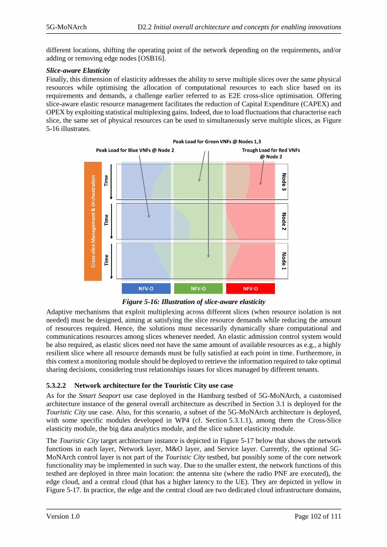
5G-MoNArch D2.2 Initial overall architecture and concepts for enabling innovations
Version 1.0 Page 102 of 111
different locations, shifting the operating point of the network depending on the requirements, and/or
adding or removing edge nodes [OSB16].
Slice-aware Elasticity
Finally, this dimension of elasticity addresses the ability to serve multiple slices over the same physical
resources while optimising the allocation of computational resources to each slice based on its
requirements and demands, a challenge earlier referred to as E2E cross-slice optimisation. Offering
slice-aware elastic resource management facilitates the reduction of Capital Expenditure (CAPEX) and
OPEX by exploiting statistical multiplexing gains. Indeed, due to load fluctuations that characterise each
slice, the same set of physical resources can be used to simultaneously serve multiple slices, as Figure
5-16 illustrates.
Figure 5-16: Illustration of slice-aware elasticity
Adaptive mechanisms that exploit multiplexing across different slices (when resource isolation is not
needed) must be designed, aiming at satisfying the slice resource demands while reducing the amount
of resources required. Hence, the solutions must necessarily dynamically share computational and
communications resources among slices whenever needed. An elastic admission control system would
be also required, as elastic slices need not have the same amount of available resources as e.g., a highly
resilient slice where all resource demands must be fully satisfied at each point in time. Furthermore, in
this context a monitoring module should be deployed to retrieve the information required to take optimal
sharing decisions, considering trust relationships issues for slices managed by different tenants.
5.3.2.2 Network architecture for the Touristic City use case
As for the Smart Seaport use case deployed in the Hamburg testbed of 5G-MoNArch, a customised
architecture instance of the general overall architecture as described in Section 3.1 is deployed for the
Touristic City use case. Also, for this scenario, a subset of the 5G-MoNArch architecture is deployed,
with some specific modules developed in WP4 (cf. Section 5.3.1.1), among them the Cross-Slice
elasticity module, the big data analytics module, and the slice subnet elasticity module.
The Touristic City target architecture instance is depicted in Figure 5-17 below that shows the network
functions in each layer, Network layer, M&O layer, and Service layer. Currently, the optional 5G-
MoNArch control layer is not part of the Touristic City testbed, but possibly some of the core network
functionality may be implemented in such way. Due to the smaller extent, the network functions of this
testbed are deployed in three main location: the antenna site (where the radio PNF are executed), the
edge cloud, and a central cloud (that has a higher latency to the UE). They are depicted in yellow in
Figure 5-17. In practice, the edge and the central cloud are two dedicated cloud infrastructure domains,
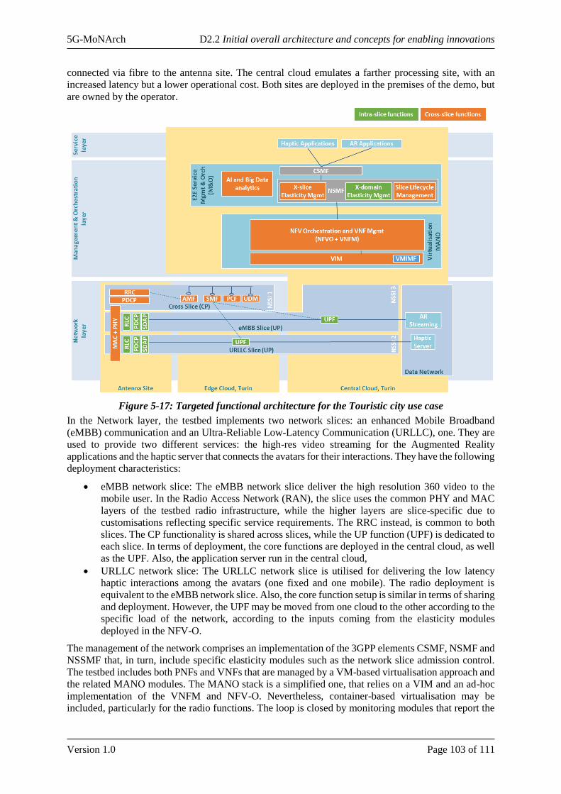
5G-MoNArch D2.2 Initial overall architecture and concepts for enabling innovations
Version 1.0 Page 103 of 111
connected via fibre to the antenna site. The central cloud emulates a farther processing site, with an
increased latency but a lower operational cost. Both sites are deployed in the premises of the demo, but
are owned by the operator.
Figure 5-17: Targeted functional architecture for the Touristic city use case
In the Network layer, the testbed implements two network slices: an enhanced Mobile Broadband
(eMBB) communication and an Ultra-Reliable Low-Latency Communication (URLLC), one. They are
used to provide two different services: the high-res video streaming for the Augmented Reality
applications and the haptic server that connects the avatars for their interactions. They have the following
deployment characteristics:
• eMBB network slice: The eMBB network slice deliver the high resolution 360 video to the
mobile user. In the Radio Access Network (RAN), the slice uses the common PHY and MAC
layers of the testbed radio infrastructure, while the higher layers are slice-specific due to
customisations reflecting specific service requirements. The RRC instead, is common to both
slices. The CP functionality is shared across slices, while the UP function (UPF) is dedicated to
each slice. In terms of deployment, the core functions are deployed in the central cloud, as well
as the UPF. Also, the application server run in the central cloud,
• URLLC network slice: The URLLC network slice is utilised for delivering the low latency
haptic interactions among the avatars (one fixed and one mobile). The radio deployment is
equivalent to the eMBB network slice. Also, the core function setup is similar in terms of sharing
and deployment. However, the UPF may be moved from one cloud to the other according to the
specific load of the network, according to the inputs coming from the elasticity modules
deployed in the NFV-O.
The management of the network comprises an implementation of the 3GPP elements CSMF, NSMF and
NSSMF that, in turn, include specific elasticity modules such as the network slice admission control.
The testbed includes both PNFs and VNFs that are managed by a VM-based virtualisation approach and
the related MANO modules. The MANO stack is a simplified one, that relies on a VIM and an ad-hoc
implementation of the VNFM and NFV-O. Nevertheless, container-based virtualisation may be
included, particularly for the radio functions. The loop is closed by monitoring modules that report the
5G-MoNArch D2.2 Initial overall architecture and concepts for enabling innovations
Version 1.0 Page 104 of 111
current load to the management modules that use this information (e.g., network load, cpu load) to
trigger both cross-slice and intra slice elasticity algorithms.
5G-MoNArch D2.2 Initial overall architecture and concepts for enabling innovations
Version 1.0 Page 105 of 111
6 Conclusions and Outlook
This deliverable has refined the baseline architecture of 5G-MoNArch (from [5GM-D2.1]) towards the
“Initial Overall Architecture”. Particularly, the design of the 5G-MoNArch overall functional
architecture has followed the baseline requirements and related KPIs for 5G-MoNArch [5GM-D6.1]
and identified gaps from [5GM-D2.1]. Building on the target KPIs and the gaps identified, the main
contribution here is to design an architecture that (i) takes the current SotA on 5G architectures, from
previous projects as well as standardisation efforts, (ii) addresses the gaps identified within those
architectures, and (iii) provides a complete architecture design, comprising SotA and novel modules as
well as the descriptions of interfaces between them.
The proposed architecture consists of four different layers identified as Service layer, Management &
Orchestration (M&O) layer, Controller layer, and Network layer. A key contribution of this deliverable
is the definition of the role of each layer, the relationship between layers, and the identification of the
required internal modules within each of the layers. In the proposed architecture, multiple management
domains for E2E network slice deployment and operation have been explored from both 3GPP and ETSI
NFV perspectives. In particular, the proposed initial architecture extends the reference architectures
proposed by 3GPP and ETSI NFV by building on these architectures while addressing several gaps
identified within the corresponding baseline models.
In order to meet E2E network slice requirements and operation, several intra-slice and cross-slice (i.e.,
inter-slice) innovation elements have been identified that can impact the operation of the CN or RAN
NFs. In terms of inter-slice management and control, the following modules have been developed: (i)
slice-aware RRM with both intra and inter-RAN configuration modes, (ii) utilisation of network and UE
data analytics in slice selection and radio resource optimisation, and (iii) slice-aware functional
operation and admission control. These functions require novel algorithms and solutions that are critical
in order to realise and efficiently operate network slices’ resources. The fundamental guidelines for these
solutions have been defined in this deliverable.
The architecture design has also addressed the interaction between intra-slice and cross-slice control
functions and different implementation options for the control functions’ realisation at RAN-level. In
this context, the interactions needed for several functionalities between intra- and inter slice control
functions at CN and RAN levels have been identified, namely (i) mobility management, (ii) radio access
technology selection or (iii) context sharing. The conceptual interaction between these functions will be
leveraged in further refinements of the architecture to specify the required interfaces for these
interactions.
The Controller layer is an optional architectural layer of 5G-MoNArch RAN consisting of intra-slice
and cross-slice controllers, for re-programmability and functional re-configuration of decomposed RAN
functions. The use of these layers will depend on the need for providing this level of programmability
and flexibility for specific network functions.
Beyond the overall architecture design, another key contribution of this report is the intermediate design
of some of the key modules within the architecture to address various identified gaps. To this end, three
enabling innovations (and the associated network functionalities) have been developed, namely flexible
cloudification of the mobile network protocol stack, adaptive network slicing via inter-slice control and
management, and experiment- and implementation-driven modelling and optimisation. Novel
approaches for the design of these modules have been presented here, including a preliminary evaluation
for many of the procedures.
The ultimate goal of the proposed architecture is to allow for the instantiation of slices that can satisfy
specific requirements. Therefore, the proposed architecture accommodates potential NFs and solutions
to achieve slice resiliency, security, and elasticity. These functions can be thus instantiated by the 5G-
MoNArch architecture when deploying slices that need to provide the corresponding services.
Remaining work towards the final deliverable D2.3 includes the final design of the overall architecture,
in particular the “internals” of the innovative modules identified within the architecture and the
respective interfaces. In conjunction with WPs 3 and 4, the final novel functions and algorithms for
resource-elastic operation as well as for customised security and resilience will be integrated into the
5G-MoNArch D2.2 Initial overall architecture and concepts for enabling innovations
Version 1.0 Page 106 of 111
overall architecture of the addressed use cases and testbeds. This will also comprise the work on the
concrete network slice blueprints that are required when employing the 5G-MoNArch slice design and
slice lifecycle management operations. These will provide the conceptual foundation for the concrete
implementation work in WP 5 as well as the evaluation and validation of WP 6.
5G-MoNArch D2.2 Initial overall architecture and concepts for enabling innovations
Version 1.0 Page 107 of 111
7 References
[3GPP-RP180554] 3GPP TSG RAN #79 RP-180554, “Plan for finalizing all NR architecture
options,” March 2018.
[3GPP TS 23.501] 3GPP TS23.501 “System Architecture for the 5G System; Stage 2,” Release
15.
[3GPP TR 23.786] 3GPP TR 23.786, “Study on architecture enhancements for EPS and 5G
System to support advanced V2X services,” Release 16.
[3GPP TR 23.791] 3GPP TR 23.791, “Study of enablers for Network Automation for 5G,”
Release 16.
[3GPP TS 28.530] 3GPP TS 28.530, “Management and orchestration of networks and network
slicing; Concepts, use cases and requirements,” Release 15
[3GPP TS 28.541] 3GPP TS 28.541 “Management and orchestration of networks and network
slicing; NR and NG-RAN Network Resource Model (NRM); Stage 2 and stage
3,” Release 15.
[3GPP TS 28.543] 3GPP TS 23.501 “Management and orchestration of networks and network
slicing; 5G Core Network (5GC) Network Resource Model (NRM); Stage 2
and stage 3,” Release 15.
[3GPP TR 28.801] 3GPP TR 28.801, “Study on management and orchestration of network slicing
for next generation network,” Release 15.
[3GPP TS 36.300] 3GPP TS 36.300, “Evolved Universal Terrestrial Radio Access (E-UTRA) and
Evolved Universal Terrestrial Radio Access Network (E-UTRAN); Overall
description; Stage 2,” Release 8 (V15.1.0).
[3GPP TS 38.211] 3GPP TS 38.211, “NR; Physical channels and modulation,” v15.0.0, Dec.
2017.
[3GPP TS 38.300] 3GPP TS 38.300, “NR; Overall description; Stage-2,” v15.1.0, April 2018.
[3GPP TS 38.401] 3GPP TS 38.401, “NG-RAN; Architecture description,” v 15.1.0, April 2018.
[3GPP TS 38.470] 3GPP TS 38.470, “NG-RAN; F1 general aspects and principles,” v15.1.0,
April 2018.
[5GARCH17-
WPv2]
5G PPP WG Architecture, Architecture White Paper v2.0, “View on 5G
Architecture,” Dec. 2017.
[5GM-D2.1] 5G-MoNArch Deliverable D2.1, “Baseline architecture based on 5G-PPP
Phase 1 results and gap analysis,” Oct. 2017.
[5GM-D3.1] 5G-MoNArch, Deliverable D3.1, “Initial resilience and security analysis,”
June 2018.
[5GM-D4.1] 5G-MoNArch, Deliverable D4.1, “Architecture and mechanisms for resource
elasticity provisioning,” June 2018.
[5GM-D6.1] 5G-MoNArch, Deliverable D6.1, “Documentation of Requirements and KPIs
and Definition of Suitable Evaluation Criteria,” September 2017.
[5GM-D6.2] 5G-MoNArch, Deliverable D6.2, “Methodology for verification and validation
of 5G-MoNArch architectural innovations,” July 2018.
[5GN-D2.3] 5G NORMA, Deliverable D2.3, “Evaluation architecture design and socio-
economic analysis - final report,” December 2017.
[ATM18] I.A. Alimi, A.L. Teixeira, P.P. Monteiro, “Toward an Efficient C-RAN Optical
Fronthaul for the Future Networks: A Tutorial on Technologies, Requirements,
Challenges, and Solutions,” IEEE Comm. Survey & Tutorials, vol. 20, no. 1,
2018.
[BRZ+15] Ö. Bulakci, Z. Ren, C. Zhou, et al, “Towards Flexible Network Deployment in
5G: Nomadic Node Enhancement to Het Net,” June 2015.
[CSS+16] S. Costanzo, et al., “Service-Oriented Resource Virtualization for Evolving
TDD Networks Towards 5G,” Wireless Communications and Networking
Conference (WCNC), 2016.
[Doc] Docker, https://www.docker.com/
5G-MoNArch D2.2 Initial overall architecture and concepts for enabling innovations
Version 1.0 Page 108 of 111
[ETSI ENI] ETSI Experiential Networked Intelligence, Online available at
http://www.etsi.org/images/files/ETSIWhitePapers/etsi_wp22_ENI_FINAL.p
df
[ETSI ENI17] ETSI White Paper, “Improved operator experience through Experiential
Networked Intelligence (ENI),” 1st Edition – October 2017.
[ETSI MEC16] ETSI GS MEC 003, “Mobile Edge Computing (MEC); Framework and
Reference Architecture, V1.1.1,” March 2016.
[ETSI NFV13] ETSI GS NFV 002, “Network Function Virtualisation (NFV) Architectural
Framework, V1.1.1,” October 2013.
[ETSI NFV16] ETSI GS NFV-IFA 014, “Network Functions Virtualisation (NFV);
Management and Orchestration; Network Service Templates Specification,
V2.1.1,” October 2016.
[ETSI NFV17] ETSI GR NFV-EVE 012, “Network Functions Virtualisation (NFV) Release
3; Evolution and Ecosystem; Report on Network Slicing Support with ETSI
NFV Architecture Framework, V3.1.1,” December 2017.
[FNK+16] X. Foukas, N. Nikalein, M. Kassem, M. Marina, and K. Kontovasilis,
“FlexRAN: A Flexible and Programmable Platform for Software-Defined
Radio Access Networks,” 12th International Conference on emerging
Networking EXperiments and Technologies, 2016.
[GBL+12] I. Grondman, L. Busoniu, G. A. D. Lopes et R. Babuska, “A Survey of Actor-
Critic Reinforcement Learning: Standard and Natural Policy Gradients,” IEEE
Transactions on Systems, Man, and Cybernetics, Part C (Applications and
Reviews), pp. 1291-1307, 2012.
[GDC18] G. Ghatak, A. De Domenico, M. Coupechoux, “Small Cell Deployment Along
Roads: Coverage Analysis and Slice-Aware RAT Selection,” submitted to
IEEE Transaction on Communications, 2018.
[GGS+16] I. Gomez-Miguelez et al., “srsLTE: an open-source platform for LTE evolution
and experimentation,” Proceedings of the Tenth ACM International Workshop
on Wireless Network Testbeds, Experimental Evaluation, and
Characterization. ACM, 2016.
[GSA WP17] GSA white paper on “5G Network Slicing for Vertical Industries,” September
2017.
[HJS18] B. Han, L. Ji, H. D. Schotten, “Slice as an Evolutionary Service: Genetic
Optimization for Inter-Slice Resource Management in 5G Networks,” to
appear in IEEE Access, 2018, https://arxiv.org/pdf/1802.04491.pdf
[iJOIN D3.3] iJOIN (INFSO-ICT-317941), Deliverable D3.3, “Final definition and
evaluation of MAC and RRM approaches for RANaas,” October 2012
[LPL+17] Y. Li, E. Pateromichelakis, J. Luo, N. Vucic, W. Xu, “Resource Management
Considerations for 5G millimeter-Wave Backhaul / Access Networks,” IEEE
Communications Magazine Special Issue on Agile Resource Management in
5G, July 2017.
[NGMN15] Next Generation Mobile Networks (NGMN) Alliance, “5G White Paper,”
February 2015, Online available at
https://www.ngmn.org/uploads/media/NGMN_5G_White_Paper_V1_0.pdf
[NGMN18] Next Generation Mobile Networks (NGMN) Alliance, “Service-Based
Architecture in 5G”, January 2018, Online available at
https://www.ngmn.org/fileadmin/ngmn/content/downloads/Technical/2018/1
80119_NGMN_Service_Based_Architecture_in_5G_v1.0.pdf
[NI] National Instruments, USRP-2944, USRP Software Defined Radio
Reconfigurable Device, http://www.ni.com/en-us/support/model.usrp-
2944.html
[NNM+14] N. Nikaein, et al., “OpenAirInterface: A flexible platform for 5G research,”
ACM SIGCOMM Computer Communication Review 44.5, pp. 33-38, 2014.

5G-MoNArch D2.2 Initial overall architecture and concepts for enabling innovations
Version 1.0 Page 109 of 111
[OAI] Open Air Interface, www.openairinterface.org
[ODK16] T. O. Olwal; K. Djouani; A. M. Kurien, “A Survey of Resource Management
towards 5G Radio Access Networks,” IEEE Communications Surveys &
Tutorials, no.99.
[ONF14] Open Networking Foundation, “SDN architecture,” Issue 1, ONF TR-502,
June 2014.”
[ONY+11] K. Okino, et al., “Pico Cell Range Expansion with Interference Mitigation
toward LTE-Advanced Heterogeneous Networks,” IEEE ICC Workshops,
2011, pp. 1–5.
[OSB16] J. Oueis, E.C. Strinati, and S. Barbarossa, “Distributed mobile Cloud
Computing: A multi-user Clustering Solution,” IEEE Int. Conf. on
Communications (ICC 2016), 23-27 May, 2016.
[PJD+15] S. Parsaeefard, V. Jumba, M. Derakhshani et T. Le-Ngoc, “Joint resource
provisioning and admission control in wireless virtualised networks,” Wireless
Communications and Networking Conference (WCNC), pp. 2020-2025, 2015.
[PP17] E. Pateromichelakis and C. Peng, “Selection and Dimensioning of slice-based
RAN Controller for adaptive Radio Resource Management,” Wireless
Communications and Networking Conference (WCNC), 2017
[PSW+17] E. Pateromichelakis, K. Samdanis, Q. Wei, P. Spapis, “Slice-tailored Joint Path
Selection & Scheduling in mm-Wave Small Cell Dense Networks,” IEEE
Globecom, 2017.
[SKE+12] Z. Shen, et.al, “Dynamic Uplink-Downlink Configuration and Interference
Management in TD-LTE.” IEEE Communication Magazine, Vol.50, No.11,
Nov. 2012.
[SRSLTE] Open-source srsLTE, https://github.com/srsLTE
[SSC+17] V. Sciancalepore, K. Samdanis, X. Costa-Perez, D. Bega, M. Gramaglia, A.
Banchs, “Mobile Traffic Forecasting for Maximizing 5G Network Slicing
Resource Utilization,” IEEE INFOCOM, 2017.
[SSS+16] V. Sciancalepore, K. Samdanis, R. Shrivastava, A. Ksentini, X. Costa-Perez,
“A service-tailored TDD cell-less architecture,” IEEE 27th Annual
International Symposium on Personal, Indoor, and Mobile Radio
Communications (PIMRC), Valencia, 2016, pp. 1-6.
[Wil12] B. Wilder, “Cloud Architecture Patterns,” O’Reilly Publications, 2012.
[XRAN] xRAN: Next Generation RAN Architecture, http://www.xran.org/
[YT16] F. Zarrar Yousaf, T. Taleb, “Fine-grained resource-aware virtual network
function management for 5G carrier cloud,” IEEE Network 30.2, pp. 110-115,
2016.
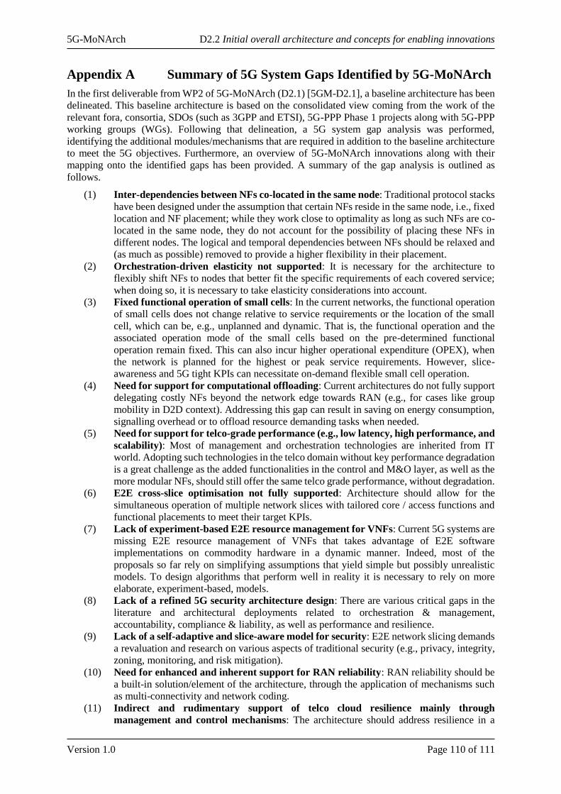
5G-MoNArch D2.2 Initial overall architecture and concepts for enabling innovations
Version 1.0 Page 110 of 111
Appendix A Summary of 5G System Gaps Identified by 5G-MoNArch
In the first deliverable from WP2 of 5G-MoNArch (D2.1) [5GM-D2.1], a baseline architecture has been
delineated. This baseline architecture is based on the consolidated view coming from the work of the
relevant fora, consortia, SDOs (such as 3GPP and ETSI), 5G-PPP Phase 1 projects along with 5G-PPP
working groups (WGs). Following that delineation, a 5G system gap analysis was performed,
identifying the additional modules/mechanisms that are required in addition to the baseline architecture
to meet the 5G objectives. Furthermore, an overview of 5G-MoNArch innovations along with their
mapping onto the identified gaps has been provided. A summary of the gap analysis is outlined as
follows.
(1) Inter-dependencies between NFs co-located in the same node: Traditional protocol stacks
have been designed under the assumption that certain NFs reside in the same node, i.e., fixed
location and NF placement; while they work close to optimality as long as such NFs are co-
located in the same node, they do not account for the possibility of placing these NFs in
different nodes. The logical and temporal dependencies between NFs should be relaxed and
(as much as possible) removed to provide a higher flexibility in their placement.
(2) Orchestration-driven elasticity not supported: It is necessary for the architecture to
flexibly shift NFs to nodes that better fit the specific requirements of each covered service;
when doing so, it is necessary to take elasticity considerations into account.
(3) Fixed functional operation of small cells: In the current networks, the functional operation
of small cells does not change relative to service requirements or the location of the small
cell, which can be, e.g., unplanned and dynamic. That is, the functional operation and the
associated operation mode of the small cells based on the pre-determined functional
operation remain fixed. This can also incur higher operational expenditure (OPEX), when
the network is planned for the highest or peak service requirements. However, slice-
awareness and 5G tight KPIs can necessitate on-demand flexible small cell operation.
(4) Need for support for computational offloading: Current architectures do not fully support
delegating costly NFs beyond the network edge towards RAN (e.g., for cases like group
mobility in D2D context). Addressing this gap can result in saving on energy consumption,
signalling overhead or to offload resource demanding tasks when needed.
(5) Need for support for telco-grade performance (e.g., low latency, high performance, and
scalability): Most of management and orchestration technologies are inherited from IT
world. Adopting such technologies in the telco domain without key performance degradation
is a great challenge as the added functionalities in the control and M&O layer, as well as the
more modular NFs, should still offer the same telco grade performance, without degradation.
(6) E2E cross-slice optimisation not fully supported: Architecture should allow for the
simultaneous operation of multiple network slices with tailored core / access functions and
functional placements to meet their target KPIs.
(7) Lack of experiment-based E2E resource management for VNFs: Current 5G systems are
missing E2E resource management of VNFs that takes advantage of E2E software
implementations on commodity hardware in a dynamic manner. Indeed, most of the
proposals so far rely on simplifying assumptions that yield simple but possibly unrealistic
models. To design algorithms that perform well in reality it is necessary to rely on more
elaborate, experiment-based, models.
(8) Lack of a refined 5G security architecture design: There are various critical gaps in the
literature and architectural deployments related to orchestration & management,
accountability, compliance & liability, as well as performance and resilience.
(9) Lack of a self-adaptive and slice-aware model for security: E2E network slicing demands
a revaluation and research on various aspects of traditional security (e.g., privacy, integrity,
zoning, monitoring, and risk mitigation).
(10) Need for enhanced and inherent support for RAN reliability: RAN reliability should be
a built-in solution/element of the architecture, through the application of mechanisms such
as multi-connectivity and network coding.
(11) Indirect and rudimentary support of telco cloud resilience mainly through
management and control mechanisms: The architecture should address resilience in a
5G-MoNArch D2.2 Initial overall architecture and concepts for enabling innovations
Version 1.0 Page 111 of 111
structured way taking into account different aspects (e.g., individual network elements
(NEs)/NFs, telco cloud components, fault management, and failsafe mechanisms).
(12) Need for (radio) resource sharing strategy for network slices: While basic mechanisms
for multi-slice resource management have been studied in 5G-PPP Phase 1 projects, elastic
mechanisms need to be devised that improve the utilisation efficiency of the computational
and radio resources by taking advantage of statistical multiplexing gains across different
network slices.