Embed Size (px)
Citation preview
June, 2018
5G-Ready NFV Infrastructure A Transformation Journey Towards Full Automation Version 1.0 Technical White paper Authors Daniel Alfredsson (Telia Company) Roberto Muggianu (Telia Company) Toni Satola (Telia Company) Sumit Verdi (VMware)
Table of Contents 1 Foreword ................................................................................................................. 3
2 Modernization towards 5G ..................................................................................... 7
3 Target Reference Environment ............................................................................. 8 3.1 A Conceptual Architectural Framework ........................................................................... 8 3.2 Infrastructure and Cloud Execution Environment (ICEE) Definition.................................. 9
ICEE Characteristics: Consciously Chosen Inhomogeneity. ........................................ 9 3.3 Network Service Characterization ................................................................................. 11 3.4 Business Goals Driving 5G-Ready Infrastructure........................................................... 12
Efficiency in the Infrastructure Provisioning and Utilization ........................................ 12 Ability to Respond Quickly to New Orders, Services, and Customer Needs............... 12
4 Network Slicing and its Lifecycle ........................................................................ 12 4.1 Network Slice Characterization and Concepts ............................................................... 12
Definition ................................................................................................................... 12 Concept of Tenant ..................................................................................................... 12 Network Slice Modeling ............................................................................................. 13
4.2 Network Slice Lifecycle.................................................................................................. 14 4.3 Heal and Elasticity ......................................................................................................... 18 4.4 Termination ................................................................................................................... 19
5 ICEE Characteristics ............................................................................................ 19 5.1 Resource Management ................................................................................................. 19
Resource Isolation ..................................................................................................... 19 Management of Physical Infrastructure Resources .................................................... 21
5.2 Capability and Availability Exposure .............................................................................. 21 5.3 Networking Capabilities Abstraction .............................................................................. 22 5.4 Higher Level of Abstraction ........................................................................................... 23 5.5 Security ......................................................................................................................... 23 5.6 Automation .................................................................................................................... 24
Integrated Operational Intelligence ............................................................................ 24 Closed-Loop and Dynamic Optimizations .................................................................. 25
6 Summary ............................................................................................................... 25
Page 3 of 27
1 Foreword In a recent paper we highlighted the importance of Cloud Native Software and applications and we detailed the wanted behavioral aspects of Telco Cloud Application Software. Those requirements, now become mandatory within the Telia Company procurement of software for telco grade applications, have also been analyzed in combination with the underlying technology platform providing abstraction and cloud functionalities. While we fundamentally believe in the independence of layers, we have ascertained the need for tight collaboration between application software and technology infrastructure platforms at the architectural level to maximize performance and effectiveness in terms of e.g. resource consumption.
This paper addresses the next level of the end-to-end architecture in terms of requirements we see emerging for the infra layer, especially for the upcoming new generation of services and 5G.
While we continue to expand and operate new software functions in our network, it is becoming more and more evident that the demand and the expectations on the ‘cloud platform’ have to match the sophistication of newly automated application software. As indicated above, the principle of independence and autonomy between the network layers still require strong interaction at an architectural level to ensure maximization of performance, regardless of the nature of the cloud platform and the underlying technology or solutions (VM, Containers, ESX, Openstack and the like)
5G is taking the requirements (and the expectations) to the next level and we currently see that it is fundamental to follow a rigorous design and architectural approach to maximize interoperability, guarantee full utilization of the overall software capabilities and, in particular, to aim for adoption of open interfaces and standards as much as possible.
First a conceptual architectural framework is established to consistently guide developers through the complexity of the several scenarios that characterize 5G. These include, but are not limited to, both traditional cloud deployment arrangements (Private, Public and Hybrid) but emerging needs for Edge deployments (in this paper Edge is characterized manly by applications that require super stringent physical performance to be met, in terms of latency, reliability, deterministic physical performances etc.).
While we expect the framework to be in constant evolution and change, it is important to establish a rigorous level of governance that involves in a strict dialogue Carriers architects, Infrastructure/cloud technology owners and the Application software providers.
From the Architectural framework, the paper then introduce the concept of Infrastructure and Cloud Execution Environment (ICEE) that encompasses the end to end nature of the various use cases by embracing the concept of Network Resources as a whole (e.g.
Page 4 of 27
including compute resource distribution but also Transport solutions and networking requirements).
The paper puts forward some critical concepts we fundamentally believe in: model-based abstraction and separation of control layers as a foundation for the so called ‘lean infrastructure’. This, together with the appropriate data model, based on common/homogeneous semantic and a rich information set, will eventually drive the long overdue new paradigm of ‘system integration’.
The above enable a truly end-to-end view of the architecture and is key to materialize the concept of Network Slices in a controlled manner, avoiding ad hoc implementations and ultimately driving scale and performance from the Network deployed base.
This has led to the considerations set out in the paper, that focus on the requirements we see coming strong from field trials and lab prototyping activities we are running within Telia Company.
Once again, we expect this to drive a constructive dialogue between carriers, vendors and the various platform communities, ultimately facilitating an effective delivery of the expectations 5G is currently creating. Mauro Costa Director – Network and Infra Telia Company
Page 5 of 27
Mobile wireless technologies have gone through systematic generational refreshes over the last three decades. The next such refresh, called 5G, isn’t just an incremental upgrade from 4G, but represents a significant leap forward. 5G promises to improve efficiency, enhance security, reduce latency times, increase network capacity, and accelerate current data connections by 10, or even 100 times. And for the first time, 5G brings wireline technologies into greater prominence and convergence with wireless infrastructure, enabling telecom carriers to extract efficiency from their full network. However, before the benefits of 5G can be widely exploited, Telco Service Providers need to invest in virtualized and cloud-based infrastructure. 5G requires both a software-driven architecture and Network Functions Virtualization, or NFV, to be successful. At VMware, we see 5G as a big opportunity and challenge for Communications Service Providers to leverage the benefits of 5G with new business models and to reassert their influence in the cloud economy. While NFV is the foundation to deliver 5G, TSPs are going to require a telecom transformation that represents a new approach to delivering agile services and enables the ability to have these services move between clouds, include private, edge, and public clouds. A key aspect of 5G networks is network slicing. For TSPs, network slicing provides the ability to divide and scale the network on an as-a-service and ‘on-demand’ basis. This requires an advanced, software-defined infrastructure that allows multiple virtual networks to be created atop a shared physical infrastructure. Virtual networks can then be customized to meet the needs of applications, services, devices, customers or other global TSPs. In 5G networks, NFV will enable a network to be separated into multiple virtual networks that can support various types of services for specific customer and market segments. Network slices will be isolated from one another in the control and data plane, so the subscriber experience will be the same as if it was a physically separate network. For CSPs, network slicing enables new business opportunities. Services such as remote health and surgery, smart metering, smart drones, and connected cars all require connectivity, but with vastly different network characteristics. New technologies, such as virtualization, network programmability, and network slicing will enable networks to be customized and meet the needs for each application. As a result, new products and services can be introduced to market quickly, and can be easily customized, deployed, and adapted to fast-changing demands. This paper in close collaboration with Telia and VMware outlines the characterization of the network driven by the 5G push and the requirements that TSPs should take into consideration to support new services and SLAs. In addition, the paper highlights the requirement to provide an efficient network infrastructure that can deliver services as
Page 6 of 27
the best price point, along with creating an on-demand network to support new business consumption models and a frequent service rollout cadence. We have also created the foundation for what we believe is essential in ensuring TSPs can deliver an intelligent network that can proactively optimize network resources and preserve the integrity of policies and SLAs while delivering services. The paper highlights the importance of delivering integrated operational intelligence that provides real-time analytics in the infrastructure and provides a converged view of performance across the infrastructure resources. In addition, we outline the process for TSPs to optimize their networks and create an elastic network that can dynamically increase or reclaim infrastructure resources as needed to preserve the defined network slice model. We believe 5G to deliver massive changes as it will create a larger, more efficient network that offers new possibilities for developers and TSPs. The collaborative nature of 5G may also prompt more partnering across the ecosystem and alter the competitive landscape of the industry. Hybrid environments that leverage the best of both worlds, coupling hyper scale public cloud infrastructures like those from Amazon Web Services, or IBM, and the NFV enhanced clouds from TSPs, could become the basis for new marketplaces for consumer and enterprise applications and tools. Gabriele Di Piazza Vice President Solutions, Telco NFV VMware
Page 7 of 27
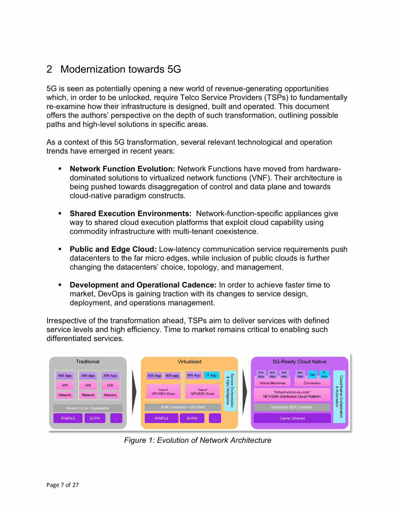
2 Modernization towards 5G 5G is seen as potentially opening a new world of revenue-generating opportunities which, in order to be unlocked, require Telco Service Providers (TSPs) to fundamentally re-examine how their infrastructure is designed, built and operated. This document offers the authors’ perspective on the depth of such transformation, outlining possible paths and high-level solutions in specific areas. As a context of this 5G transformation, several relevant technological and operation trends have emerged in recent years:
§ Network Function Evolution: Network Functions have moved from hardware-dominated solutions to virtualized network functions (VNF). Their architecture is being pushed towards disaggregation of control and data plane and towards cloud-native paradigm constructs.
§ Shared Execution Environments: Network-function-specific appliances give way to shared cloud execution platforms that exploit cloud capability using commodity infrastructure with multi-tenant coexistence.
§ Public and Edge Cloud: Low-latency communication service requirements push datacenters to the far micro edges, while inclusion of public clouds is further changing the datacenters’ choice, topology, and management.
§ Development and Operational Cadence: In order to achieve faster time to market, DevOps is gaining traction with its changes to service design, deployment, and operations management.
Irrespective of the transformation ahead, TSPs aim to deliver services with defined service levels and high efficiency. Time to market remains critical to enabling such differentiated services.
Figure 1: Evolution of Network Architecture
Page 8 of 27
3 Target Reference Environment This section introduces and outlines several concepts used throughout the remaining sections of the document. More specifically it:
§ Describes the conceptual architecture assumed throughout the document; § Defines the characteristics of the cloud infrastructure within this context; § Characterizes the nature of the services running on top of this infrastructure; § Highlights some of the TSPs’ business objectives and related challenges.
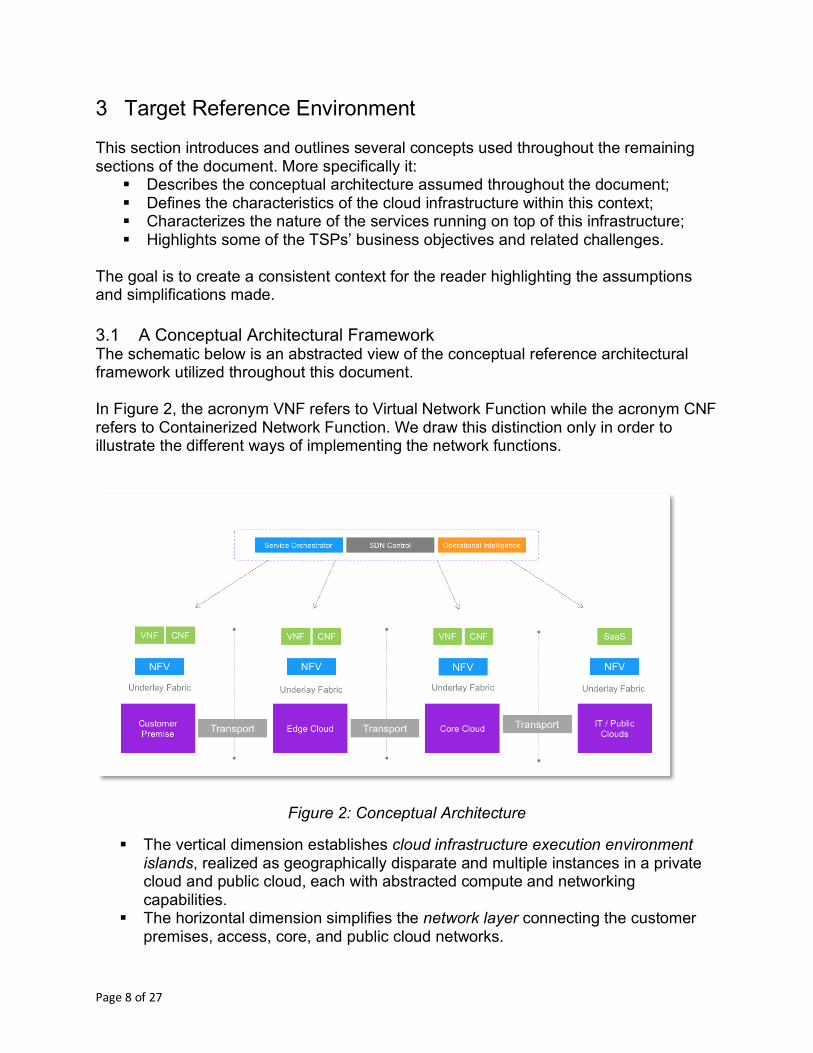
The goal is to create a consistent context for the reader highlighting the assumptions and simplifications made. 3.1 A Conceptual Architectural Framework The schematic below is an abstracted view of the conceptual reference architectural framework utilized throughout this document. In Figure 2, the acronym VNF refers to Virtual Network Function while the acronym CNF refers to Containerized Network Function. We draw this distinction only in order to illustrate the different ways of implementing the network functions.
Figure 2: Conceptual Architecture
§ The vertical dimension establishes cloud infrastructure execution environment islands, realized as geographically disparate and multiple instances in a private cloud and public cloud, each with abstracted compute and networking capabilities.
§ The horizontal dimension simplifies the network layer connecting the customer premises, access, core, and public cloud networks.
Page 9 of 27
This bi-dimensional representation is clearly a conceptual framework that simplifies and hides the actual topologies, but it is descriptive enough to capture the essential aspects of this discussion. 3.2 Infrastructure and Cloud Execution Environment (ICEE) Definition In the context of this document, the term infrastructure refers to the TSP’s domain of computing resources (in general, computing resource refers to CPU, memory and storage, for example, packaged in the server or server-equivalent format) and transport equipment (enabling the VNF/CNF running on the computing resources to communicate among them), and overarching service composition and operations management functions for lifecycle management. Consider the following characterizations of this infrastructure:
1. Only the packaged computing resources that support dynamic placement of Virtual/ Container Network Functions are hereafter considered. (A server that is rigidly associated with a specific application, for example, will not be considered as part of this real estate of computing resources.)
2. Networking equipment is only considered if it has some configuration or programming capability; physical links do not comply with this definition, while routers, pure forwarding plane equipment or network-virtualized functions do.
3. The software layer that enables the computing resource to be abstracted and available for consumption is also included. This is the lowest level of abstraction, and we refer to it as the cloud execution environment.
Raw computing resources and network equipment are underlying capabilities, which the cloud execution environment and the upper layers of abstractions will consume.
ICEE Characteristics: Consciously Chosen Inhomogeneity. Several drivers will influence the actual build of the infrastructure defined above:
1. Natural evolution of technologies and TSP ability (geographic, organizational, economical) to adopt them;
2. 5G services requirements with their mixture of low-latency, high throughput and high connection densities;
3. Inclusion of public computing estates (public cloud providers like Microsoft and Amazon) and the opportunity they offer also in terms of operating model.
While the first of these drivers does not represent anything new from a TSP perspective, it is worth noting that it establishes a decidedly different context that, as the TSP strives to maintain its target of quality and efficiency, will require taking a radically different approach than in the past.
Page 10 of 27
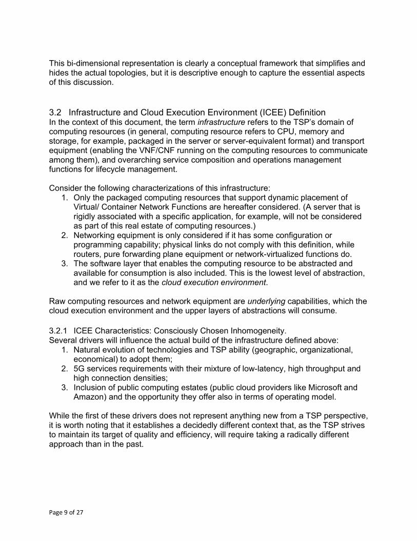
3.2.1.1 Compute Resource Considerations The compute resource is expected to have varying levels of diversity by typology, capability and suppliers. (For example, smart NICs capabilities will introduce diversity in order to reach better efficiency.) The balance between operational complexity and cost efficiency will strongly drive the entropy landing point. It is expected that the computing resource distribution will change from the current centralized models into a more distributed one, enabled by the disaggregation offered by the VNF/CNF in an attempt to improve modularity and scalability. In the following schematic, this aggregation of computing resources will be referred to as cloud islands.
Figure 3: Computing Power Distribution Model
We also assume that different consumption and administrative models, both within the TSP control and interacting with other public cloud providers, become available. 3.2.1.2 Networking Resource Considerations One of the largest operating challenges for a TSP is the wide range of variability for networking resources and their management system. While even today TSPs clearly try to reduce complexity by phasing out technologies that are too old or too rigid, this diversity is not going to go away completely, driven by the need to comply in the most efficient possible way with the differing needs coming from the different service offerings. Therefore, the networking piece for ICEE will still be a blend of technologies offering
§ SLAs ranging from best effort (e.g. internet connection) to stringent Quality of Service (QoS);
§ Different domains of ownership (within the datacenter and WAN) and different build-out strategies (e.g., rent vs. build);
§ Different management boundaries as those, for example, mandated by law and regulations;
§ Different transport and protocol technologies (legacy and evolutionary).
Page 11 of 27
3.2.1.3 Cloud Execution Environment For the software layer providing both the computing resources abstraction and the basis for network abstraction capabilities we assume the following:
§ Low or very low diversity of the software layers (e.g. hypervisors technologies, containers) when owned by the TSP;
§ Management systems to be available for those cloud execution environments, exposing open APIs towards upper layers of management in a consistent way to the greatest extent possible.
3.3 Network Service Characterization Let us now consider network services and what requirements they will have, especially driven by the 5G push. We note here that this push just makes more evident some of those requirements whose need is otherwise already present. (Network service does not necessarily connote a service to an end customer.) We assume the following regarding a network service:
1. It is a complex composition of unitary network functions extending from simple VNF/CNF to entire pieces of networks, including physical functions, with complex interaction among its components.
2. It features deployment across many cloud islands. 3. It comprises lifespan that is not determined a priori and is heavily dependent on
customer demand so it can start at any time, will have a short set-up time and it can be terminated at any time.
4. It comes with different SLAs spanning the cloud islands. 5. It offers security defined by the service and/or defined by the customers but
maintained across the lifecycle. So in extreme synthesis, we assume that network service characteristics are much more dynamic than today’s experience, posing a clear challenge to TSPs.
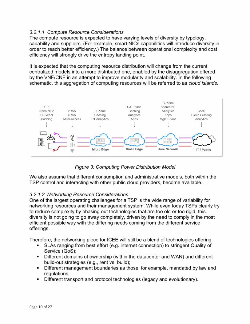
Figure 4: Multi-Tenant Service Composition across Clouds
Figure 4 offers a high-level example of network slices where different network services have different deployment configurations across the TSP’s cloud infrastructure topology.
Page 12 of 27
3.4 Business Goals Driving 5G-Ready Infrastructure At the conclusion of this section, we will look into the assumed business goals from a TSP point of view as they are clearly essential targets for the design of its infrastructure. The implications of this business need fulfillment will become clear in this document’s next sections.
Efficiency in the Infrastructure Provisioning and Utilization The infrastructure is a resource provider, with allocation and utilization partitioned by applications and customers. The goal is to use the resource provided by the infrastructure as efficiently as possible. One immediate implication of this never-ending search for efficiency is the need to update the TSP infrastructure to offer consistently the best price point for the service delivered. This may include a mix of private and public cloud islands.
Ability to Respond Quickly to New Orders, Services, and Customer Needs New business consumption approaches will necessitate subscriptions, self-service, and on-demand types of models to circumvent the current 3-6 month service rollout cadence. A key goal for the TSP is to be able to provide services in an agile workflow, with the required reliability and quality. Let us highlight here the word ‘required’ and point out that an undistinguished level of service – typically very high – for all the services is an unsustainable model going forward.
4 Network Slicing and its Lifecycle “A well implemented 5G-ready infrastructure supports more products and services and even per-customer unique services deployments than a traditional network. It should have support for new use-cases on demand without network-wide changes.” This statement begs a logical question: What are the characteristics that make an infrastructure 5G-ready? To provide an answer, we will consider the relevant case of a network slice (in the conceptual format of “Gedankenexperiment”) and we will trace its lifecycle highlighting its departures from the current way of working and the implications for the infrastructure. 4.1 Network Slice Characterization and Concepts
Definition A network slice (NS) is in this context defined as a composition of dedicated compute, network and VNF/CNF; it potentially spans across different cloud islands and it is associated with a set of operational policies and service level agreements (SLAs). Each network slice is associated with a model created using high-level descriptive language, the importance of which will become clear in the following.
Concept of Tenant In general, a network slice will serve a customer type (business or consumer) but this concept of customer needs to be distinguished from the administration (the tenant) of
Page 13 of 27
the network slice, itself. The administrator of the network slice can be the customer, itself, or one or more different entities.
Network Slice Modeling Before we delve into the lifecycle management of a network slice, let’s consider the different entities that need to interact with the infrastructure layer in order to identify the specific role of the infrastructure itself.
1. Virtual Function Controller – Either a generic or vendor-specific VNF manager responsible for VNF/CNF lifecycle including instantiation, scale out/in, termination, etc.
2. Network Service Orchestrator – Responsible for stitching the complete, end-to-end network slice and for the placement of its component as driven by the model associated with the slice, itself
3. Global SDN-Controller – Responsible for connecting the network slice component, again taking into account the function described in the model associated with the network slice model
4. Global Inventory Catalog – A logical repository containing the relevant set of information of the TSP infrastructure
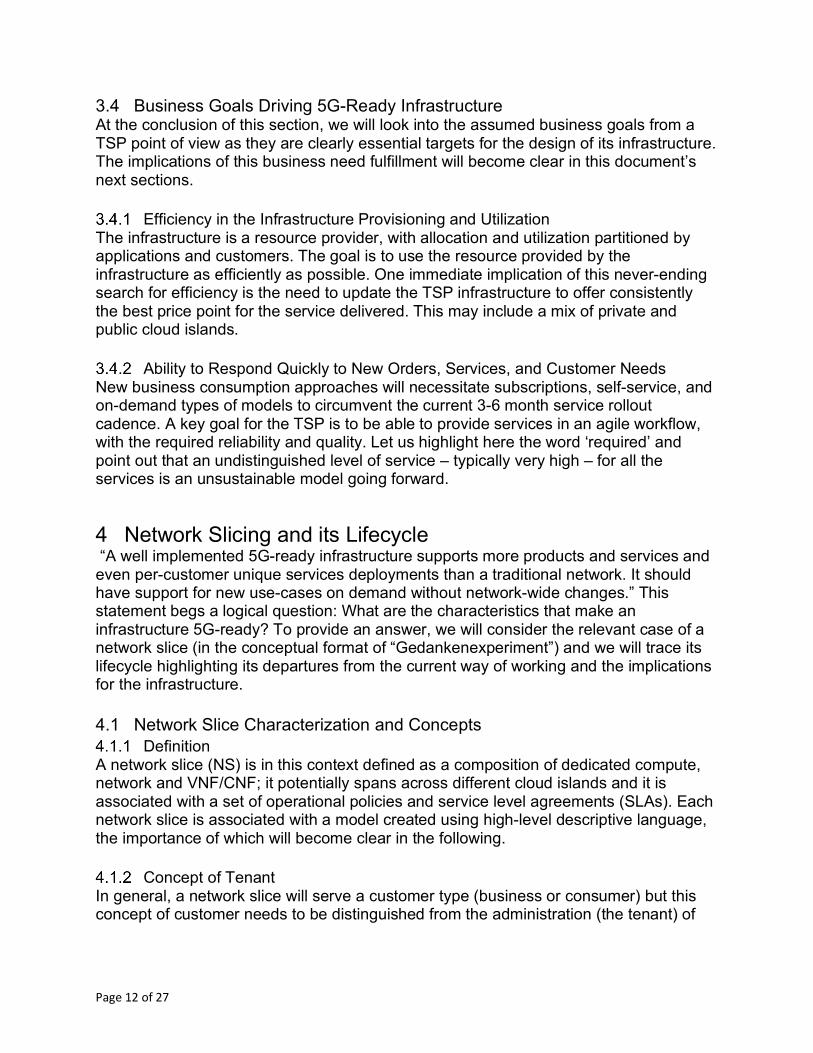
Figure 5: Network Slice Representation across Cloud Providers
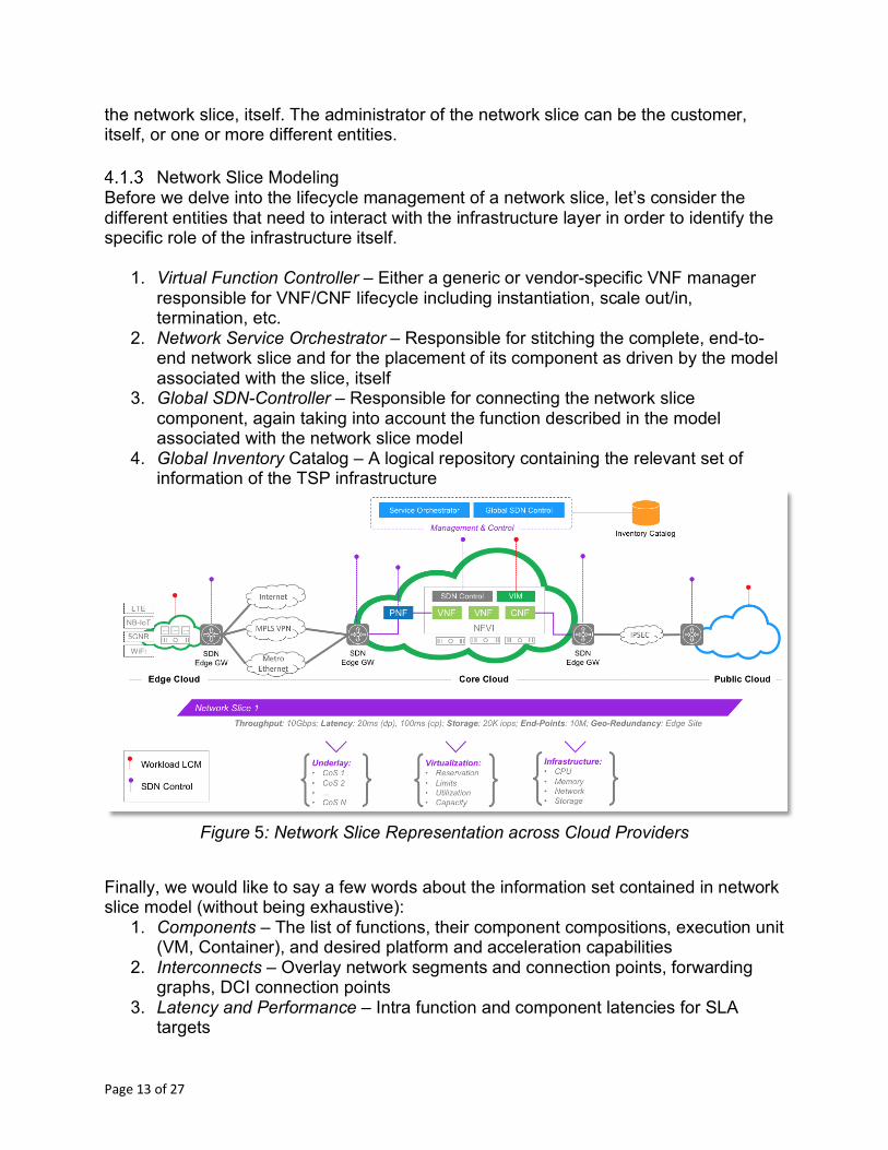
Finally, we would like to say a few words about the information set contained in network slice model (without being exhaustive):
1. Components – The list of functions, their component compositions, execution unit (VM, Container), and desired platform and acceleration capabilities
2. Interconnects – Overlay network segments and connection points, forwarding graphs, DCI connection points
3. Latency and Performance – Intra function and component latencies for SLA targets
Page 14 of 27
4. Lifecycle Policy – Auto-scaling, heal, and termination policy and enforcement control
5. Security – Policies for east-west and north-south security groups, data encryption, transport encryption, etc.
6. Availability and Recovery Time Objective – DR policies for geo-redundant active/standby backups, session replication, data protection, stretched storage, function restart, etc.
7. Priority – The notion of a general priority/importance of the workloads in case of extraordinary condition such as site failure, natural disasters, emergency, etc.
Figure 6: Conceptual Modeling of a Network Slice
4.2 Network Slice Lifecycle 4.2.1.1 Onboarding and Creation Based on the descriptions offered in the previous sections, we should assume that the network slice is described by some form of modeling language that abstracts the characteristics requested to the slice, which components need to be part of it, and how those components are connected. It is essential to have a model-based approach versus other more static representations; this is the only approach that can accommodate the needed flexibility and the dynamic nature of those network slice entities. Good modeling is vital, and while modeling can appear to be complicated, in practical terms it needn’t be overly complex. The critical steps include validating the model against established security policies and creating blueprint model outputs to be easily consumable by various parts of the infrastructure. For the above reasons, within the context of this document we will emphasize the phases where the model translates to an actual deployment. At a high-level, the first
Page 15 of 27
decision to take is where the different components need to be placed to satisfy the network slice requirements. This decision point is especially relevant when latency and availability requirements must be satisfied. Latency requirements have meaning only compared to the customer or set of customers they serve. This simple consideration implies that, at creation time, the position of the customers served by the network slice is known. It is also important to note that while not necessarily an optimal solution, one way to solve this specific problem (and not only at creation time) is to deploy the relevant functions for all the possible positions of the customer being served. (Networks are currently built in this way.) We will assume here that at creation time, it is possible to know (or to make an educated guess about) the network slice customer’s location and therefore each of the possible locations to deploy the components of the network slice in order to minimize latency. This description in terms of latency might also be given in statistical terms. It is also worth noting that:
§ Latency indication might be a function of time (i.e. depending on the number of customers).
§ The ICEE in general might be collecting this information from the access system connected.
Generally, the ICEE – even without considering extreme situations like very low latency – will need to be assertive about its characteristics so that it is possible to match this information with that required in the model describing the network slice. It is important that the ICEE characteristics can always be translated into something comparable with what is described in the model. Mapping then becomes a key integration requirement. For example, a cloud island that is able to run containers over bare metal should be able to quickly create, run and/or destroy execution environments, and these capabilities should be properly translated and exposed for the management system to be able to make the right decisions. (A similar approach should be taken for the interface to the public cloud provider.) We can further assume that the initial placement of the network slices is known within the boundary of cloud islands. This process does not differ in the basic principles from how a network service is built today; the process has simply been automated and driven by the particular requirements. It’s what comes after this phase that is fundamentally different. In practice, the connectivity required by the network slice grows while the functions are deployed, which means that it will not be possible to configure the network service in advance. The traditional preparation phase involves assigning IP addresses, defining the proper IP structure and configuration (often based on MPLS networks), and configuring the needed security infrastructure (e.g. based on firewalls). This traditional
Page 16 of 27
approach is not compatible with the dynamic configuration requested by the network slice creation and therefore calls for an alternate solution. We assume that the various components of the network slice can be universally uniquely identified (according, for example, to a private logic within a TSP as well as a TSP unique identifier globally assigned) and that this information can be properly mapped – at creation time – into a set that is understood by an IP-based transport network such as the MAC address, or the IP address. At the end of this step, we know the placement and transport characteristics of the network slice components and we should now look into the problem of having them connected. Note that we cannot assume a network slice will always be composed by newly deployed components. In general, though, it will also rely on existing functions, either virtual or physical. Therefore, proper understanding of those situations and evaluation of actions on such existing elements must be properly described and placed as part of this flow. 4.2.1.2 An overlay Software-Defined Network Model In Figure 2: Conceptual Architecture we represented – albeit in a simplified way – an underlay transport network providing connectivity across cloud islands. In the following, we will assume that the technology providing this underlying architecture provides a basic IP layer as a minimum requirement. The required technology may be based on existing deployments, but it may change over time to simpler or more cost-efficient configurations. Regardless, consumers will not see a change in performance. In the following we refer to those consumers as overlay. Abstraction is equally important from a transport perspective, with a clear separation between underlay and overlay. This separation carries with it the following implications:
1. The underlay should know the location of physical assets and shortest path (IP-based) but not the location of network services. Only the overlay SDN controller knows the location of network services while the overlay is fully virtualized from the underlay. The rationale is to allow dynamic movement and introduction of new service chains. An overlay protocol is required that indicates service chain and network slice metadata, QoS parameters (for underlay and underlay mapping), and customer and security segmentation.
2. Planning and build-out for the underlay will have a different dynamic and different operational process compared to the build-out of the overlay. (Although this is a simplification, it is regarded as acceptable at this stage and one not undermining the overall picture. We are also making the assumption that several underlays might be available with different characteristics.)
The essential idea here is that the network slices deployment engine will be able to create the overlay connectivity it needs by connecting the different datacenters through any underlay with the needed features. From an ICEE perspective, this would require
Page 17 of 27
an efficient gateway functionality, able to terminate the internal cloud islands networking (which we assume here to be software driven) while properly interfacing with the underlay transport. We regard this gateway functionality as part of the cloud island. As an analogy, we see the cloud islands as enterprise sites connected through a software-defined overlay whose edge is the gateway functionalities presented above. This gateway functionality should be providing the capability to create connection at levels L2 and L3 as well as the capabilities to connect directly with the underlay whenever the connectivity required includes physical systems. Finally, this gateway functionality must also offer an API interface for a SDN controller layer to consume its capabilities. 4.2.1.3 Resource Management and Concept of Tenant and Multi-Tenancy for a
Network Slice At a high level, the concept of a tenant is associated with a certain amount of computational resources and networking resources within a cloud infrastructure and, whenever available, the policy set related to their management, including allocation, reservation and relative priority. We expect that every network slice will be associated with an SLA and this service level will be mapped to a set of resources. We further expect that the infrastructure is able to define, enforce and expose the above set of policies and also present metrics to higher-level service assurance processes (e.g. to create closed loop actions). What is the expected minimum policy that an infrastructure must be able to support? The policy needs to enlist the number of resources and the associated two levels of reservation – fully reserved or best effort. We expect as well that the cloud island is able to enforce, in the case of full reservation, that in every foreseeable situation, the resources (all types of computing resources and virtual networking resources) are guaranteed to be assigned without contention and that they will be able to signal when this situation is at risk. We can now revisit the initial discussion about tenancy and the ability to manage concurrently multiple tenants with different and possibly competing requirements. At a high level, a network slice will appear to be owned by a unique entity. This entity can decide to split the network slice into different administrative domains according to the operating model used to operate the network slice. Therefore, we expect that the different pieces of cloud islands are able to understand, adopt and expose the concept of tenant and be able to handle multi-tenancy. In situations where different network slices share a specific component, the cloud island must ensure that resource requests from the network slice owner are managed according to defined policies. (Policy and procedures can be very different: A registration, for example, might be needed and verified or a default role might be accepted.) The cloud islands, themselves, will not solve or harmonize contrasting
Page 18 of 27
requests to avoid, for example, race conditions. Instead, a level of management above must address those conditions. 4.3 Heal and Elasticity Heal and Elasticity are part of the dynamic management of a network slice. Within this context we will assume as a general case that a network slice is deployed across several distributed cloud islands according to its description, including the service level agreement requirement. We will further assume that it is possible to have visibility into the deployment status of the network slice and that we can verify the network slice against the model used to deploy it. Working under the above assumptions, the Heal operation allows us to re-establish the target situation (a defined level of availability, for example) as expressed by the model. This again highlights the importance of working in a model-driven way. However complex this rebuilding might be, this operation does not require from the ICEE any different or additional capability than the one required in the initial creation step. One practical use case for Heal is a lost site scenario either because of disaster or due to maintenance. Short of going to the extreme case of disaster recovery, Heal capability can be an effective remedy in a case where a single component of the network slice “disappears.” The behavior in a “lost site scenario” should be SLA policy-dependent. It could be either do nothing, have geo-redundancy deployment (without delay/short delay), or a self-reorganizing function (with delay). In general, ICEE might provide effective protection against HW failure and a way to avoid contention as established during the creation of the network slice, itself. It’s important to note that the above mechanisms must not be considered replacements for the resiliency mechanisms established at application level. The applications, themselves, must be able to detect failure situations and act accordingly, like asking to recreate the broken resources, for example. Elasticity is the capacity of a network slice to adapt to a change of the target set at creation time. Network slices can adapt only along certain dimensions; they cannot change in their nature. For example, if a network slice is created to grant a very low latency then it will not be able to adapt to obtain ultra-broadband capacity. In general, the capability to adapt is related to situations where the network service serves more clients. While serving more clients may necessitate adding more resources to the existing functions, an alternative approach may instead be adding additional functions into different locations (so changing the current topology). The capabilities of the modeling language and the ability of the ICEE to express the available capability and expose it through APIs are, as in the case of the creation, key enablers of elastic operations.
Page 19 of 27
Although elasticity does not present major infrastructure challenges at creation time, when it comes to dynamic lifecycle operation of the network slice, it requires “atomicity” capability, which means all components of the network slice either succeed or fail. Through automation, the infrastructure implements a concept of reservation and release of resources. ICEE reflects the expected dynamic behavior requested and optimizes the placement of workloads in order to maximize efficiency of resource utilization. Achieving this efficiency requires a granular understanding of the resources at the execution unit and an understanding of which tenant the execution unit belongs to. 4.4 Termination Termination is the lifecycle operation by which a network slice will cease its services to customers. In general, this means that the structure created for that network slice will be destroyed and the corresponding resources released. Alternatively, there may be situations in which the resources will not be released completely but kept in a state of retention, with all metadata and data available to restore service as required without delay.
5 ICEE Characteristics Although the concept of slicing has been employed for many years, it has been achieved by building vertical resource, network, and application isolation to deliver different services. However, building several network slices on a common shared infrastructure poses new challenges, some of which have been presented in the previous sections. In this section we will provide an overview of the relevant characteristics that an ICEE must have to become 5G-ready. 5.1 Resource Management
Resource Isolation Workloads are moving toward micro-services architectures with separation of control and user planes. As resource demands for services vary by use case and by edge-core distributions, effective partitioning of cloud island resources for compute and networking is a key requirement. Storage architectures can be assigned today in a dedicated or shared manner across network slices and network functions, meeting desired operational attributes for the network slice, functions, and applications.
Page 20 of 27
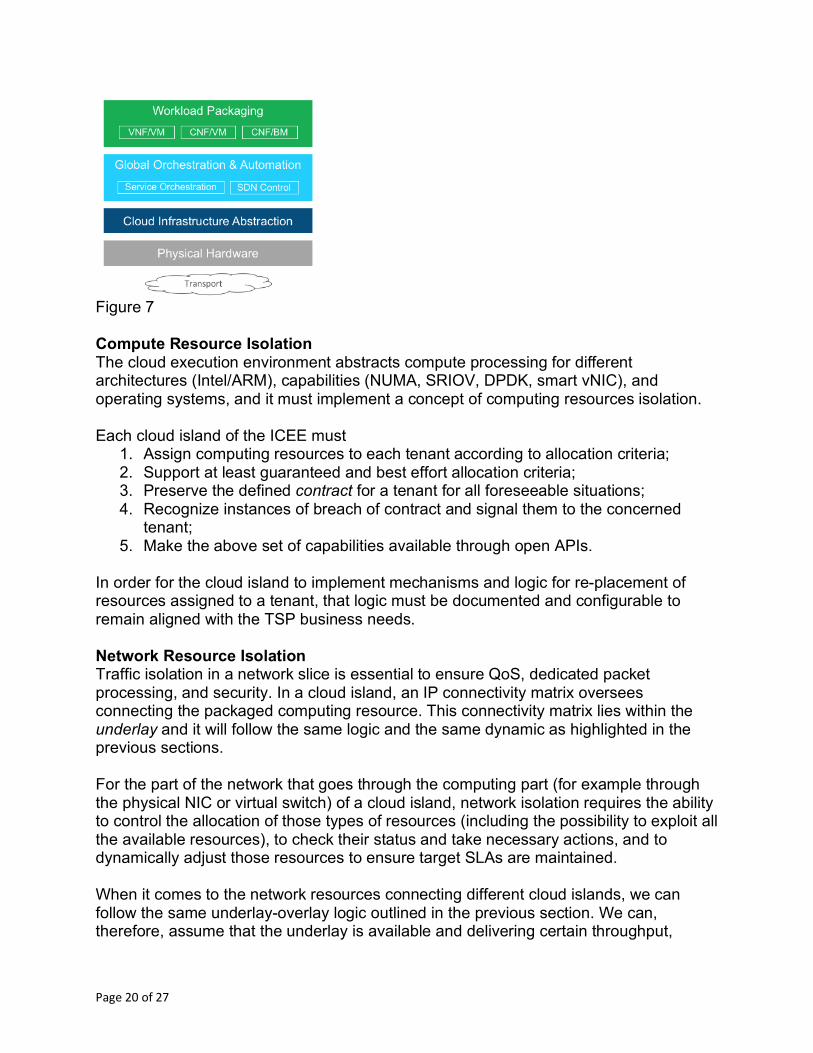
Figure 7 Compute Resource Isolation The cloud execution environment abstracts compute processing for different architectures (Intel/ARM), capabilities (NUMA, SRIOV, DPDK, smart vNIC), and operating systems, and it must implement a concept of computing resources isolation. Each cloud island of the ICEE must
1. Assign computing resources to each tenant according to allocation criteria; 2. Support at least guaranteed and best effort allocation criteria; 3. Preserve the defined contract for a tenant for all foreseeable situations; 4. Recognize instances of breach of contract and signal them to the concerned
tenant; 5. Make the above set of capabilities available through open APIs.
In order for the cloud island to implement mechanisms and logic for re-placement of resources assigned to a tenant, that logic must be documented and configurable to remain aligned with the TSP business needs. Network Resource Isolation Traffic isolation in a network slice is essential to ensure QoS, dedicated packet processing, and security. In a cloud island, an IP connectivity matrix oversees connecting the packaged computing resource. This connectivity matrix lies within the underlay and it will follow the same logic and the same dynamic as highlighted in the previous sections. For the part of the network that goes through the computing part (for example through the physical NIC or virtual switch) of a cloud island, network isolation requires the ability to control the allocation of those types of resources (including the possibility to exploit all the available resources), to check their status and take necessary actions, and to dynamically adjust those resources to ensure target SLAs are maintained. When it comes to the network resources connecting different cloud islands, we can follow the same underlay-overlay logic outlined in the previous section. We can, therefore, assume that the underlay is available and delivering certain throughput,
Page 21 of 27
latency, and availability characteristics. In this context, the characteristics of the underlay are known either because they are built on purpose (as a static type of information) or because the underlay, itself, is able to present those capabilities and warn when it is not able to maintain that service level.
Management of Physical Infrastructure Resources The infrastructure layer will evolve in technology to support different hardware architectures, compute acceleration and network acceleration. This evolution is inevitable with even just homogeneous cloud islands. So even considering one such island, the infrastructure and the first level of abstraction must be able to embed new physical capability with just a simple operation. The simplicity extends to the first layer of abstraction itself. It must be possible to perform an upgrade of that software layer with simple operations and without the need to consume additional hardware. Further, changes in the operation of the infrastructure must not have an impact on the network slices that are using them.
Infrastructure Foundation Manager – This can be seen as a centralized function to turn up new (or expand existing) cloud islands. This includes setting up the software environment, execution components, hardware abstractions, and inventory of the newly added resources and capability. Once the infrastructure is presented and made available, it will also require periodic software and hardware upgrades. It is also responsible for interacting with public cloud providers (AWS, Azure, etc.) to request resources and services necessary for the network slice.
5.2 Capability and Availability Exposure Throughout the previous sections, a key assumption is that the workload placement function evaluates the network slice to determine where best to place the various components of the network slice, itself. The implication is the necessity to have an inventory of the infrastructure capability and to have it populated with the relevant information to make the right choice. Run-time metrics can be leverage by analytical and closed-loop automation functions. The population will happen at building time – which represents its static component – but must also happen in a dynamic way as some the infrastructure capabilities might vary over time. The infrastructure is, therefore, required to keep an updated status (its own inventory) and be able to provide this status to other systems according to a specified and consistent interface. The inventory catalog provides the following example capabilities:
• Metadata – This represents the basic information about the infrastructure cloud instance with respect to its physical geo location, administrative domain, region, clusters, server information, type of network interconnections with the DCI gateways, execution units (VNF, CNF in VM, CNF on BM) supported, customers, and tenants.
Page 22 of 27
• Capability – The model-driven onboarding dictates intent-based principles; the infrastructure will not expose every class of fine-grained platform capabilities but will instead focus on key aspects like latency; bandwidth; hardware accelerated for packet processing, transcoding, and other; computing speeds; storage IOPS; availability to meet SLAs; instance and site redundancy; and so forth. The inherent capabilities such as smart NICs, SRIOV, NUMA, DPDK are seen as technology enablers for compute and networking which are controlled and managed by the infrastructure itself.
• Capacity – This represents the available capacity at the cloud instance including virtual CPU, Memory, Storage, Network throughput, reservations, etc.
• Utilization – As the infrastructure is consumed and optimized (workload migrations, time of day elasticity, termination) this reports the current aggregate utilization of CPU, memory, network, and storage across resource cluster groups; the number of tenants deployed; the minimum resource reservation/guarantees allocated; consumption against the reservations; etc.
• Cloud Interconnects – The cloud infrastructure environment should provide dynamic latency and utilization metrics across the DC gateway interconnect to neighboring / connected clouds, enabling more intelligent workload placement decisions and runtime traffic optimization, shaping, and remediation.
• Resource placement – Location of where the workloads are placed in the cloud instance, including any updates to when they migrate or terminate.
5.3 Networking Capabilities Abstraction To fulfill the network slice lifecycle, a cloud island should be able to logically connect the components of the network slice, itself, and preserve this connectivity in case of re-positioning of the components. This logical connectivity (an overlay connectivity) is equivalent to creating an L2 segment or L3 topology within the border of a cloud island. For L3 topology, this capability must be implemented as a logical routing capability across the distributed infrastructure. Though compelling use cases are surfacing for stretched L2 networking. It is defined in control policy and optimized dynamically to create highly resilient networks and eliminate points of consolidation and bottlenecks. An upper layer of management is required to create consistent overlay connectivity across cloud islands. Network protocols such as MP-BGP/EVPN enable the network slice stitching across cloud infrastructure, simplified to manage and operate across distributed clouds and virtualized infrastructure. This capability should match the expected target of efficiency. Compared to a more traditional logical connectivity implementation, the cloud infrastructure may provide more elaborated capabilities, including the ability to steer traffic according to L7 protocol and according to defined policy. For example, all HTTP traffic may need to traverse a content filtering function (like video through transcoding/compression) while SIP passes through without any treatment. This capability may help efficient and dynamic chaining with a cloud island.
Page 23 of 27
5.4 Higher Level of Abstraction It may prove to be highly effective for the cloud infrastructure itself to be programmed by consuming the same model used to describe the end-to-end network slice descriptive language. This will execute on the various resource and business-driven policies to operationalize the segment of the network slice within each and every cloud instance. In this approach, the overall network service Orchestrator will be less concerned with the platform/hardware capabilities, including EPA, and other intrinsic characteristics, but it will be able to identify homogeneous pieces of the network slice modeling to be given as input to a single cloud island. 5.5 Security With the higher degree of abstraction in the overall modernized cloud infrastructure, there is a larger awareness created for security within the cloud. Cloud infrastructure enables new classes of operations impacting the multi-technology, multi-vendor ecosystem of physical, logical, application, controllers and so on. As such security concepts will be based on two pillars:
1. A “zero-trust” and 2. A policy-driven, programmable security model
With self-service capability for service and operations management, it is crucial to have role-based access controls baked into every tier of the cloud infrastructure, including APIs. Security policies will be defined by the Network Slice model as discussed above, which the cloud infrastructure will need to interpret, implemented and enforce within each of the cloud islands. The cloud infrastructure is seen to provide the following capabilities to support the two pillars:
• Cross-Cloud Transports –WAN transports with different classes of encrypted tunnels exist across the distributed clouds. As defined by the network slice policy, the infrastructure should terminate the cloud traffic on the appropriate WAN end-points on the north-south traffic plane.
• Cloud Execution Environment –Security policies need to be attached to the workload functions (VNF/CNF). Using the security policies defined in the network slice model, the cloud infrastructure should plan micro-segmentation polices by evaluating real-time flow traffic across functions and communicate any violations to those policies at run-time. The infrastructure needs to ensure the workload security policies and bindings are fully portable as workloads move through the cloud islands.
• Workload Security – Workloads in the cloud infrastructure open up a larger concern for trust in the areas of dynamic onboarding, multi-vendor packages, and movement of such functions across clusters. Workload “fingerprints” should be
Page 24 of 27
validated by the hypervisor and/or hardware during the onboarding process and before execution.
• Data Encryption – Man-in-the-middle and malware are not uncommon and more of a concern in abstracted cloud environments. Cloud infrastructure exposes (through modeling and APIs) overlay network and data encryption capabilities that can be leveraged by the network slice. The network slice model will define policies which can be enforced by the infrastructure, including leveraging any hardware offloading available. Note that the encryption keys are owned by the network service (and owner).
Security policy and profiling should be defined in policy, applied across the infrastructure ubiquitously, and attached to workloads through their lifecycle. By default, the zero trust security model should prevail. 5.6 Automation The ICEE needs to make sure the network functions operating within the software and resource layers are kept in check and delivered to the service level targets defined. Such automation is essential from service creation to runtime workload optimizations. The lifetime of an application is not defined a priori; as such it requires dynamic elasticity to accommodate short lifespans or a more permanent and therefore static states. Additionally, workloads may migrate within the cloud infrastructure instance, to another private cloud, or burst into a public cloud. The cloud infrastructure needs to be able to (a) capture the operational intelligence at run-time; (b) execute optimizations within the cloud infrastructure and provide notifications of any corrections; and (c) trigger higher order service orchestration functions to take action. The cloud infrastructure needs to collect and compute operational intelligence and apply that consistently for closed-loop automation.
Integrated Operational Intelligence At the heart of automation is the need for real-time analytical intelligence in the infrastructure, providing a converged view of performance across various layers of software and resource abstractions and physical functions. Operational intelligence is computed on a continuous basis across infrastructure resources, with awareness of workload elasticity and mobility. The network slice model defines the SLA parameters for the (subset) service chain and components executing in the cloud island. The cloud infrastructure will use such policies and parameters (latency, throughput, QoS scores, resource utilization, etc.) to enforce closed-loop compliance discussed in the next section. The operational intelligence data should additionally be reported to the global inventory system and also to any global (cross-cloud) analytics component for end-to-end network-slice analysis. Industry standardization by way of information models is key to
Page 25 of 27
ensuring consistent modeling and parameterization across multiple cloud provider platforms deployed in private and public offerings.
Closed-Loop and Dynamic Optimizations Calculated analytical data are essential to proactively optimize workloads and networking. The cloud infrastructure needs to preserve the defined network slice model operating in the instance, and any optimizations should ensure integrity of those policies and SLAs. Workloads will undergo changes in capacity and performance, and the infrastructure will optimize itself with levels of automation. The infrastructure can take action itself as defined by policy or delegate to the global service orchestrator functions. Per the network slice model optimization parameters, the cloud infrastructure is able to increase or reclaim infrastructure resources (CPU, memory, storage, network) and reservations as needed. Alternatively, the infrastructure may migrate workloads to a less loaded host or cluster with available reservations. The optimization function needs to cooperate with various cloud infrastructure components to ensure there isn’t any congestion at any abstracted layers (compute, storage, and networking), and also any changes in performance characteristics with other clouds/end-point on the WAN links. In the case where the infrastructure needs to delegate optimization to higher order functions, the infrastructure will trigger closed-loop notifications to the service orchestration or VNF-M function to execute the scale/heal/restart functions. The orchestrator may spin up a new function in the same or different cloud infrastructure environment, execute DR policies on the redundant instance, add more capacity to the DCI transports, or burst workloads into a public cloud. In the event of dynamic optimizations and recovery, the infrastructure must update the global inventory catalog of changes and also distribute those notifications to all components involved in the lifecycle and operations management chain.
6 Summary Transformation to 5G and to full automation require TSP to deeply change the way the cloud infrastructure -- ICEE in the document -- is perceived, built, integrated and operated as highlighted in the previous chapters. The above shift is needed to reach the efficiency and degree of automation and abstraction required for modern TSP to keep up with all the current and the potential market opportunities offered by the disruptive digital transformation our world is undergoing. In key point down below, key features expected for a 5G ready infrastructure:
1. Even for basic type of ‘cloud islands’, programmable and very strict dynamic control over all type of managed resources is essential to guarantee required level of service.
Page 26 of 27
2. Service availability and quality are key. A cloud island environment needs to ensure zero impact to services in hardware and software upgrades, service insertion, and dynamic workload optimizations/migrations.
3. To enable a model-driven deployment and lifecycle of network slices, ICEE itself need to fully expose its capability at run-time. Such exposure of capability shall become an essential requirement for integration of ‘additional’ pieces.
4. Networking capabilities and their abstractions – both within a cloud island and among them – are essential to be available and fully programmable.
5. In order for the various abstraction layers – services, orchestration, cloud infrastructure, and underlay transports – to interoperate effectively, a new level of messaging needs to be defined as contracts between the layers, from capability exposure to run-time lifecycle and utilization metrics.
6. The cloud infrastructure needs to be intelligent and adaptive to the dynamic nature of resource assignment and consumption with dedicated and shared tenancy models.
7. Analytics will be core to not only the infrastructure but also to the end-to-end network slice lifecycle management for elasticity, reliability and availability of services.
Page 27 of 27
[Closing Page] About Telia Company We’re Telia Company, the New Generation Telco. Our 19,600 talented colleagues serve millions of customers every day in one of the world’s most connected regions. With a strong connectivity base, we’re the hub in the digital ecosystem, empowering people, companies and societies to stay in touch with everything that matters 24/7/365 - on their terms. Headquartered in Stockholm, the heart of innovation and technology, we’re set to change the industry and bring the world even closer for our customers. www.teliacompany.com About VMware The world is changing quickly as advances in cloud, mobile and edge computing, IoT and AI unlock innovation at unprecedented speed. For enterprises, embracing disruptive change while keeping everything running smoothly is a constant challenge, resulting in imperfect compromises between delivering today and investing for tomorrow. VMware software connects, manages, automates and secures the world’s digital infrastructure to reliably deliver the apps, services and experiences transforming business and society. The company enables organizations to flex and harness new technology quickly, without disrupting operations. VMware streamlines the journey for customers to become digital businesses that deliver better experiences to their customers and empower employees to do their best work, in turn driving growth. VMware’s compute, cloud, mobility, networking and security offerings provide a dynamic and efficient digital foundation to more than 500,000 customers globally, aided by an ecosystem of 75,000 partners, so businesses can embrace innovation at scale for competitive advantage. www.vmware.com/go/nfv


![ETSI GS NFV-INF 004 V1.1 · [1] ETSI GS NFV-INF 001 (V1.1.1): "Network Functions Virtualisation (NFV); Infrastructure Overview". 2.2 Informative references References are either specific](https://img.pdfslide.net/doc/110x75/5f797d6d7032da5bd63a2da3/etsi-gs-nfv-inf-004-v11-1-etsi-gs-nfv-inf-001-v111-network-functions.jpg)