Embed Size (px)
Citation preview

Power Transmission & Distribution
5kV and 15kV Metal-Clad SwitchgearType GM-SG
InstructionsInstallationOperationMaintenanceE50001-U229-A284-X-US00
Hazardous voltages and high-speed moving parts.
Will cause death, serious injury or property damage.
Always de-energize and ground the equipment beforemaintenance. Read and understand this instruction manualbefore using equipment. Maintenance should be performedonly by qualified personnel. The use of unauthorized parts inthe repair of the equipment or tampering by unqualifiedpersonnel will result in dangerous conditions which will causedeath, severe injury or equipment damage. Follow all safetyinstructions contained herein.
IMPORTANT
The information contained herein is general in nature and not intended for specific
application purposes. It does not relieve the user of responsibility to use sound practices in
application, installation, operation, and maintenance of the equipment purchased. Siemens
reserves the right to make changes in the specifications shown herein or to make
improvements at any time without notice or obligations. Should a conflict arise between the
general information contained in this publication and the contents of drawings or
supplementary material or both, the latter shall take precedence.
QUALIFIED PERSON
For the purpose of this manual, a qualified person is one who is familiar with the
installation, construction or operation of the equipment and the hazards involved.
In addition, this person has the following qualifications:
(a) is trained and authorized to de-energize, clear, ground, and tag circuits
and equipment in accordance with established safety procedures.
(b) is trained in the proper care and use of protective equipment such as rubber
gloves, hard hat, safety glasses or face shields, flash clothing, etc., in accordance
with established safety practices.
(c) is trained in rendering first aid.
NOTE
These instructions do not purport to cover all details or variations in equipment, nor toprovide for every possible contingency to be met in connection with installation, operation,or maintenance.Should further information be desired or should particular problems arisewhich are not covered sufficiently for the purchaser's purposes, the matter should bereferred to the local sales office.
The contents of this instruction manual shall not become part of or modify any prior orexisting agreement, commitment or relationship. The sales contract contains the entireobligation of Siemens Power Transmission & Distribution, Inc. The warranty contained in thecontract between the parties is the sole warranty of Siemens Power Transmission &Distribution, Inc. Any statements contained herein do not create new warranties or modifythe existing warranty.

1
Introduction and Safety . . . . . . . . . . . . . . . . . . . . . . . . 2Introduction . . . . . . . . . . . . . . . . . . . . . . . . . . . . . . . . . . . 2Qualified Person . . . . . . . . . . . . . . . . . . . . . . . . . . . . . . . 2Signal Words . . . . . . . . . . . . . . . . . . . . . . . . . . . . . . . . . . 2Field Service Operation and Warranty Issues . . . . . . . . . 2
General Description . . . . . . . . . . . . . . . . . . . . . . . . . . . .3Introduction . . . . . . . . . . . . . . . . . . . . . . . . . . . . . . . . . . .3Scope . . . . . . . . . . . . . . . . . . . . . . . . . . . . . . . . . . . . . . . .3General Description . . . . . . . . . . . . . . . . . . . . . . . . . . . . .3
Receiving, Shipping and Storage . . . . . . . . . . . . . . .4-7Receiving . . . . . . . . . . . . . . . . . . . . . . . . . . . . . . . . . . . . .4Identification . . . . . . . . . . . . . . . . . . . . . . . . . . . . . . . . . .4Inspection and Unpacking . . . . . . . . . . . . . . . . . . . . . . . .4Shipping Damage Claims . . . . . . . . . . . . . . . . . . . . . . . . .4Lifting & Moving . . . . . . . . . . . . . . . . . . . . . . . . . . . . . . .5Indoor Switchgear . . . . . . . . . . . . . . . . . . . . . . . . . . . . . .5Lifting Indoor Switchgear with Crane . . . . . . . . . . . . . . .5Moving Switchgear in Obstructed Areas
Without a Crane . . . . . . . . . . . . . . . . . . . . . . . . . . . . . . .5Final Movement of Assembly . . . . . . . . . . . . . . . . . . . . .6Storage: Indoor Switchgear . . . . . . . . . . . . . . . . . . . . . . .7Storage: Shelter-Clad Outdoor Switchgear . . . . . . . . . . .7Storage: Non-Walk-In Outdoor Switchgear . . . . . . . . . . .7Storage: Type GMSG Vacuum Circuit Breakers
and Lift Truck . . . . . . . . . . . . . . . . . . . . . . . . . . . . . . . . .7
Installation . . . . . . . . . . . . . . . . . . . . . . . . . . . . . . . . .8-22Preparation for Installation . . . . . . . . . . . . . . . . . . . . . . .8Foundation - General Requirements . . . . . . . . . . . . . . . .8Indoor Foundations . . . . . . . . . . . . . . . . . . . . . . . . . . . . .8Outdoor Foundations . . . . . . . . . . . . . . . . . . . . . . . . . . .8Installing Shipping Sections . . . . . . . . . . . . . . . . . . . . . .13Installing Switchgear with Throat Connection
to Power Transformer . . . . . . . . . . . . . . . . . . . . . . . . .13Anchoring, Leveling, and Assembling
Indoor Switchgear . . . . . . . . . . . . . . . . . . . . . . . . . . . .14Anchoring and Leveling Outdoor
Shelter-Clad Switchgear . . . . . . . . . . . . . . . . . . . . . . . .14Assembly of Single-Aisle Shelter-Clad Switchgear . . . .15Assembly of Common-Aisle Shelter-Clad Switchgear . .15Assembly of Single-Aisle Shelter-Clad Switchgear
with Work Space . . . . . . . . . . . . . . . . . . . . . . . . . . . . .15Expanding Length of Existing Shelter-Clad
Switchgear by Addition of Units . . . . . . . . . . . . . . . . .16Anchoring, Leveling, and Assembling Conventional
Outdoor (Non-Walk-In) Switchgear . . . . . . . . . . . . . . .16Expanding Length of Existing Conventional Outdoor
(Non-Walk-In) Switchgear by Addition of Units . . . . .17
Electrical Connections . . . . . . . . . . . . . . . . . . . . . .23-32Bus Bar . . . . . . . . . . . . . . . . . . . . . . . . . . . . . . . . . . . . . .23Bus Joints . . . . . . . . . . . . . . . . . . . . . . . . . . . . . . . . . . . .23Bus Insulation . . . . . . . . . . . . . . . . . . . . . . . . . . . . . . . . .26Bus Joint Insulation - Boots . . . . . . . . . . . . . . . . . . . . . .26Bus Joint Insulation - Taping . . . . . . . . . . . . . . . . . . . . .29Transformer Bus Joints - Insulation . . . . . . . . . . . . . . . .29Primary Cable Connections . . . . . . . . . . . . . . . . . . . . . .31Secondary Control Wiring . . . . . . . . . . . . . . . . . . . . . . .31Ground Connections . . . . . . . . . . . . . . . . . . . . . . . . . . .32Temporary Ground Connections . . . . . . . . . . . . . . . . . .32
Electrical Connections . . . . . . . . . . . . . . . . . . . . . .33-37Control Power and Voltage Transformers
- General Information . . . . . . . . . . . . . . . . . . . . . . . . .33Voltage Transformers . . . . . . . . . . . . . . . . . . . . . . . . . . .33Control Power Transformer . . . . . . . . . . . . . . . . . . . . . .34Operating Sequence . . . . . . . . . . . . . . . . . . . . . . . . . . .34Current Transformers . . . . . . . . . . . . . . . . . . . . . . . . . . .37
Circuit Breaker Positions . . . . . . . . . . . . . . . . . . . .38-44Circuit Breaker Cell Preparation . . . . . . . . . . . . . . . . . . .38Circuit Breaker Racking Mechanism . . . . . . . . . . . . . . . .38Interference Blocking Plate (Rating Interlock) . . . . . . . .38Secondary Disconnect . . . . . . . . . . . . . . . . . . . . . . . . . .38Mechanism Operated Cell Switch (MOC) . . . . . . . . . . .39Truck Operated Cell Switch (TOC) . . . . . . . . . . . . . . . . .39Circuit Breaker Ground Connection . . . . . . . . . . . . . . . .39Shutter Operation . . . . . . . . . . . . . . . . . . . . . . . . . . . . .39Circuit Breaker Installation and Removal . . . . . . . . . . . .39De-Energizing Control Power to Circuit Breaker . . . . . .39Spring Discharge Check . . . . . . . . . . . . . . . . . . . . . . . . .39Removal from Cell in Indoor (if not on raised pad)
and Shelter-Clad Outdoor Switchgear . . . . . . . . . . . . .40Removal from Cell in Outdoor Non-Walk-In Enclosures,
or for Indoor Switchgear Installed on a Raised Pad . .40Racking Crank Engagement Procedure . . . . . . . . . . . . .42Circuit Breaker Racking . . . . . . . . . . . . . . . . . . . . . . . . .42Racking from DISCONNECT to CONNECT Position . . . .43Racking from CONNECT to TEST or
DISCONNECT Position . . . . . . . . . . . . . . . . . . . . . . . . .43Contact Penetration . . . . . . . . . . . . . . . . . . . . . . . . . . . .43Closed Circuit Breaker Racking Interlock . . . . . . . . . . . .43Racking Access Interlock . . . . . . . . . . . . . . . . . . . . . . . .44Trip-Free Interlock . . . . . . . . . . . . . . . . . . . . . . . . . . . . .44Spring Discharge Function . . . . . . . . . . . . . . . . . . . . . . .44
Inspection and Testing . . . . . . . . . . . . . . . . . . . . . .45-46Inspection and Testing . . . . . . . . . . . . . . . . . . . . . . . . . .45Inspection . . . . . . . . . . . . . . . . . . . . . . . . . . . . . . . . . . . .45Testing . . . . . . . . . . . . . . . . . . . . . . . . . . . . . . . . . . . . . .45Placing Equipment into Service . . . . . . . . . . . . . . . . . . .46
Maintenance . . . . . . . . . . . . . . . . . . . . . . . . . . . . . .47-49Introduction and Maintenance Intervals . . . . . . . . . . . .47Recommended Hand Tools . . . . . . . . . . . . . . . . . . . . . .47Recommended Maintenance and Lubrication . . . . . . .47Lubrication . . . . . . . . . . . . . . . . . . . . . . . . . . . . . . . . . . .48Moving Parts . . . . . . . . . . . . . . . . . . . . . . . . . . . . . . . . .48Electrical Contacts . . . . . . . . . . . . . . . . . . . . . . . . . . . . .48Cleaning Insulation . . . . . . . . . . . . . . . . . . . . . . . . . . . .49Corrosive Atmospheres . . . . . . . . . . . . . . . . . . . . . . . . .49Relays and Instruments . . . . . . . . . . . . . . . . . . . . . . . . .49Equipment Surfaces . . . . . . . . . . . . . . . . . . . . . . . . . . . .49
Accessories . . . . . . . . . . . . . . . . . . . . . . . . . . . . . . .50-51Split Plug Jumper Test Device . . . . . . . . . . . . . . . . . . . .50Test Cabinet . . . . . . . . . . . . . . . . . . . . . . . . . . . . . . . . . .50Lift Truck . . . . . . . . . . . . . . . . . . . . . . . . . . . . . . . . . . . . .50Lift Sling . . . . . . . . . . . . . . . . . . . . . . . . . . . . . . . . . . . . .50Electric Racking Accessory . . . . . . . . . . . . . . . . . . . . . . .50Type 3EF Surge Limiters . . . . . . . . . . . . . . . . . . . . . . . . .51
Contents
Note: Photos with persons in this manual are shown forillustrative purposes only - comply with NFPA 70E ElectricalSafety Requirements.
2
Introduction and Safety
Introduction
The GM-SG family of 5-15kV Metal-Clad Switchgear isdesigned to meet all applicable ANSI, NEMA and IEEEstandards. This equipment is not classified as arc-resistant switchgear, and has not been tested forresistance to internal arcing per IEEE C37.20.7.Successful application and operation of thisequipment depends as much upon proper installationand maintenance by the user as it does upon thecareful design and fabrication by Siemens.
The purpose of this Instruction Manual is to assist theuser in developing safe and efficient procedures for theinstallation, maintenance and use of the equipment.
Contact the nearest Siemens representative if anyadditional information is desired.
Qualified Person
For the purpose of this manual a Qualified Person is onewho is familiar with the installation, construction oroperation of the equipment and the hazards involved. In addition, this person has the following qualifications:
• Training and authorization to energize, de-energize, clear, ground and tag circuits and equipment in accordance with establishedsafety practices.
• Training in the proper care and use of protectiveequipment such as rubber gloves, hard hat, safetyglasses, face shields, flash clothing, etc., inaccordance with established safety procedures.
• Training in rendering first aid.
Signal Words
The signal words “Danger”, “Warning” and “Caution”used in this manual indicate the degree of hazard thatmay be encountered by the user. These words aredefined as:
Danger - Indicates an imminently hazardoussituation which, if not avoided, will result in death or serious injury.
Warning - Indicates a potentially hazardous situation which, if not avoided, could result in death or serious injury.
Caution - indicates a potentially hazardous situation which, if not avoided, may result in minor or moderate injury.
Caution (without safety alert symbol) - indicates apotentially hazardous situation which, if not avoided,may result in property damage.
Field Service Operation and Warranty Issues
Siemens can provide competent, well-trained FieldService Representatives to provide technical guidanceand advisory assistance for the installation, overhaul,repair and maintenance of Siemens equipment,processes and systems. Contact regional servicecenters, sales offices or the factory for details, ortelephone Siemens Field Service at 1-800-347-6659(919-365-2200 outside the U.S.).
For medium-voltage customer service issues, contactSiemens at 1-800-347-6659 (919-365-2200 outsidethe U.S.).
Hazardous voltages and high-speedmoving parts.
Will cause death, serious injury orproperty damage.
To avoid electrical shock, burns andentanglement in moving parts, thisequipment must be installed, operated andmaintained only by qualified personsthoroughly familiar with the equipment,instruction manuals and drawings. Read andunderstand this instruction manual beforeusing equipment.
3
General Description
Introduction
The successful performance and application of Metal-Clad Switchgear depends as much on proper installationand maintenance as it does on good design, carefulmanufacture and correct application.
Siemens Type GM-SG Metal-Clad Switchgear isprecision built equipment designed to functionefficiently under normal operating conditions. It isdesigned and manufactured to operate within theparameters established in ANSI/IEEE C37 standards forMetal-Clad Switchgear. Performance requirements ofthese standards have been met or exceeded by thesedesigns. The principal standard which applies to thisclass of switchgear is ANSI/IEEE C37.20.2, “Metal-CladSwitchgear”. This equipment is not classified as arc-resistant switchgear, and has not been tested forresistance to internal arcing per IEEE C37.20.7.
The instructions included in this manual are provided toaid you in obtaining longer and more economical servicefrom your Siemens switchgear. For proper installationand operation, this information should be distributed toyour operators and engineers.
By carefully following these instructions, difficultiesshould be avoided. However, these instructions are notintended to cover all details of variations that may beencountered in connection with the installation,operation and maintenance of this equipment.
Should additional information be desired, includingreplacement instruction manuals, contact your Siemens representative.
Scope
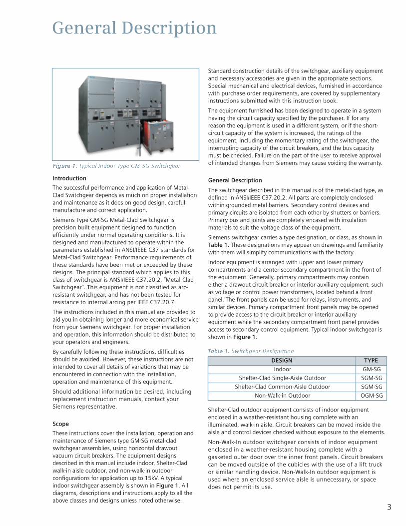
These instructions cover the installation, operation andmaintenance of Siemens type GM-SG metal-cladswitchgear assemblies, using horizontal drawoutvacuum circuit breakers. The equipment designsdescribed in this manual include indoor, Shelter-Cladwalk-in aisle outdoor, and non-walk-in outdoorconfigurations for application up to 15kV. A typicalindoor switchgear assembly is shown in Figure 1. Alldiagrams, descriptions and instructions apply to all theabove classes and designs unless noted otherwise.
Standard construction details of the switchgear, auxiliary equipmentand necessary accessories are given in the appropriate sections.Special mechanical and electrical devices, furnished in accordancewith purchase order requirements, are covered by supplementaryinstructions submitted with this instruction book.
The equipment furnished has been designed to operate in a systemhaving the circuit capacity specified by the purchaser. If for anyreason the equipment is used in a different system, or if the short-circuit capacity of the system is increased, the ratings of theequipment, including the momentary rating of the switchgear, theinterrupting capacity of the circuit breakers, and the bus capacitymust be checked. Failure on the part of the user to receive approvalof intended changes from Siemens may cause voiding the warranty.
General Description
The switchgear described in this manual is of the metal-clad type, asdefined in ANSI/IEEE C37.20.2. All parts are completely enclosedwithin grounded metal barriers. Secondary control devices andprimary circuits are isolated from each other by shutters or barriers.Primary bus and joints are completely encased with insulationmaterials to suit the voltage class of the equipment.
Siemens switchgear carries a type designation, or class, as shown inTable 1. These designations may appear on drawings and familiaritywith them will simplify communications with the factory.
Indoor equipment is arranged with upper and lower primarycompartments and a center secondary compartment in the front ofthe equipment. Generally, primary compartments may containeither a drawout circuit breaker or interior auxiliary equipment, suchas voltage or control power transformers, located behind a frontpanel. The front panels can be used for relays, instruments, andsimilar devices. Primary compartment front panels may be openedto provide access to the circuit breaker or interior auxiliaryequipment while the secondary compartment front panel providesaccess to secondary control equipment. Typical indoor switchgear isshown in Figure 1.
Shelter-Clad outdoor equipment consists of indoor equipmentenclosed in a weather-resistant housing complete with anilluminated, walk-in aisle. Circuit breakers can be moved inside theaisle and control devices checked without exposure to the elements.
Non-Walk-In outdoor switchgear consists of indoor equipmentenclosed in a weather-resistant housing complete with agasketed outer door over the inner front panels. Circuit breakerscan be moved outside of the cubicles with the use of a lift truckor similar handling device. Non-Walk-In outdoor equipment isused where an enclosed service aisle is unnecessary, or spacedoes not permit its use.
Table 1. Switchgear Designation
Figure 1. Typical Indoor Type GM-SG Switchgear
DESIGN TYPE
Indoor GM-SG
Shelter-Clad Single-Aisle Outdoor SGM-SG
Shelter-Clad Common-Aisle Outdoor SGM-SG
Non-Walk-in Outdoor OGM-SG
4
Receiving, Handling & Storage
Receiving
Each group of type GM-SG metal-clad switchgear issecurely blocked and braced for shipment. It is crated,boxed, or covered as required by shipping conditions.Whatever method of shipment, appropriateprecautions are taken to insure its safe arrival. Ifspecial handling is required, it is so indicated.Relatively delicate instruments, relays, and otherdevices are included and the switchgear assemblymust be handled carefully when unloading.
Normally, the switchgear is shipped with the associatedtype GMSG vacuum circuit breakers installed in theirrespective units, in the CONNECT position. Refer toinstruction manual E50001-U229-A285-X-US00 forinformation concerning the type GMSG circuit breakers.
Identification
When the shipment includes more than one shippinggroup or equipment for more than one substation,marking tags are attached to each crate or package foridentification. The drawing number on the tag is also onthe shipping list. The shipping list identifies the contentswith the unit numbers included in the shipping group.Refer to the general arrangement drawing for thelocation of each unit within the group lineup. Use thisinformation to simplify the assembly operation and saveunnecessary handling.
Inspection and Unpacking
Inspect the equipment as soon as possible afterreceiving for any damage that may have occurred intransit. Before unpacking, examine the package itself, asa damaged package may indicate an area of damagewithin. Be careful when unpacking equipment. The useof sledge hammers and crowbars may damage thefinish, if not the equipment itself. Use nail pullers. Afterunpacking, examine equipment for any possibledamage. Check the shipping manifest to be certain thatall items have been received. If there is a shortage, makecertain it is noted on the freight bill and contact thecarrier immediately. Notify Siemens medium voltagecustomer service at 1-800-347-6659 (919-365-2200outside the U.S.) of any shortage or damage.
Shipping Damage Claims
IMPORTANT: The way visible shipping damage is treatedby consignee prior to signing the delivery receipt candetermine the outcome of the damage claim to be filed.
Notification to carrier within the 15 day limit onconcealed damage is essential if loss resulting fromunsettled claims is to be eliminated or minimized.1. When shipment arrives, note whether equipment is
properly protected from the elements. Note trailernumber on which the equipment arrived. Note
blocking of equipment. During unloading, make sure countagrees with delivery receipt.
2. Make immediate inspection for visible damage upon arrival, andprior to disturbing or removing packaging or wrapping material.This should be done prior to unloading when possible. When totalinspection cannot be made on vehicle prior to unloading, closeinspection during unloading must be performed and visibledamage noted on the delivery receipt. Take pictures if possible.
3. Any visible damage must be noted on the delivery receipt andacknowledged with the driver's signature. The damage should bedetailed as much as possible. It is essential that a notation"Possible internal damage, subject to inspection" be included ondelivery receipt. If the driver will not sign the delivery receipt withdamage noted, the shipment should not be signed for by theconsignee or his agent.
4. Notify Siemens immediately of any damage, at 1-800-347-6659(919-365-2200 outside the U.S.).
5. Arrange for a carrier inspection of damage immediately.
IMPORTANT: Do not move equipment from the place it was setwhen unloading. Also, do not remove or disturb packaging orwrapping material prior to carrier damage inspection. Equipmentmust be inspected by carrier prior to handling after receipt. Thiseliminates loss due to claims by carrier that equipment wasdamaged or further damaged on site after unloading.
6. Be sure equipment is properly protected from any further damageby covering it properly after unloading.
7. If practical, make further inspection for possible concealeddamage while the carrier’s inspector is on site. If inspection forconcealed damage is not practical at the time the carrier’sinspector is present, it must be done within 15 days of receipt ofequipment. If concealed damage is found, the carrier must againbe notified and inspection made prior to taking any correctiveaction to repair. Also notify Siemens immediately at 1-800-347-6659 (919-365-2200 outside the U.S.).
8. Obtain the original of the carrier inspection report and forward italong with a copy of the noted delivery receipt to Siemens at 1-800-347-6659 (919-365-2200 outside the U.S.). Approval mustbe obtained by Siemens from the carrier before any repair workcan be performed. Before approval can be obtained, Siemensmust have the above referenced documents. The carrierinspection report and/or driver's signature on the delivery receiptdoes not constitute approval to repair.
Note: Any determination as to whether the equipment was properlyloaded or properly prepared by shipper for over-the-road travelcannot be made at the destination. Shipments are not released fromthe factory without a clear bill of lading. Approved methods areemployed for preparation, loading, blocking and tarping of theequipment before it leaves the Siemens factory. If the equipment isreceived in a damaged condition, this damage to the equipment hasto have occurred while en route due to conditions beyond Siemenscontrol. If the procedure outlined above is not followed by theconsignee, purchaser, or his agent, Siemens cannot be held liable forrepairs. Siemens will not be held liable for repairs in any case wherethe work was performed prior to authorization from Siemens.
5
Receiving, Handling & Storage
Lifting and Moving
There are a number of methods that can be used inhandling the switchgear which, when properlyemployed, will not damage the switchgear sections. The handling method used will be determined byconditions and available equipment at the installationsite. Lifting with a crane is the preferred method ofhandling; however, overhead obstructions or lowceilings often dictate the method to be used. Rollers,jacks or fork lift trucks may be used prior to removal ofwooden skids.
Each group of switchgear has provisions for attachinglifting equipment. Though the lift points vary in locationon indoor, Shelter-Clad outdoor, and non-walk-inoutdoor designs, all are designed for use with a crane of adequate height and capacity. To estimate themaximum required crane capacity, multiply the numberof sections to be lifted by 5300 pounds (2400 kg).
A drawing pocket (or holder) is provided on each lineupof switchgear. This drawing pocket includes a generalarrangement drawing of the switchgear lineup, plus adrawing with installation and handling instructions forthe equipment. The drawing pocket is normally locatedat the left end of the lineup. Review this informationcarefully before moving the equipment.
Indoor Switchgear
Before removing the protective packing materials,indoor equipment may be moved by crane with liftcables attached through the packaging to the liftingbars on the top of the switchgear. If crane facilities areunavailable, or if tight spaces prevent use of a crane,rollers under the skids may be used.
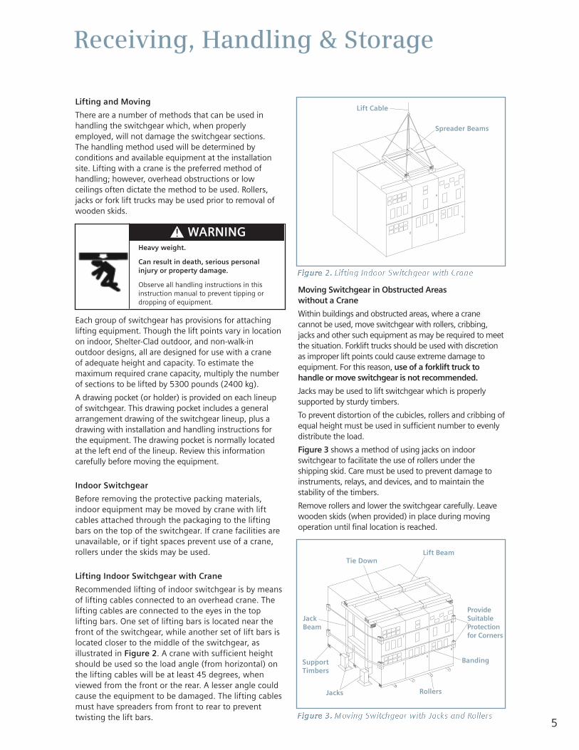
Lifting Indoor Switchgear with Crane
Recommended lifting of indoor switchgear is by meansof lifting cables connected to an overhead crane. Thelifting cables are connected to the eyes in the toplifting bars. One set of lifting bars is located near thefront of the switchgear, while another set of lift bars islocated closer to the middle of the switchgear, asillustrated in Figure 2. A crane with sufficient heightshould be used so the load angle (from horizontal) onthe lifting cables will be at least 45 degrees, whenviewed from the front or the rear. A lesser angle couldcause the equipment to be damaged. The lifting cablesmust have spreaders from front to rear to preventtwisting the lift bars.
Moving Switchgear in Obstructed Areas without a Crane
Within buildings and obstructed areas, where a cranecannot be used, move switchgear with rollers, cribbing,jacks and other such equipment as may be required to meetthe situation. Forklift trucks should be used with discretionas improper lift points could cause extreme damage toequipment. For this reason, use of a forklift truck tohandle or move switchgear is not recommended.
Jacks may be used to lift switchgear which is properlysupported by sturdy timbers.
To prevent distortion of the cubicles, rollers and cribbing ofequal height must be used in sufficient number to evenlydistribute the load.
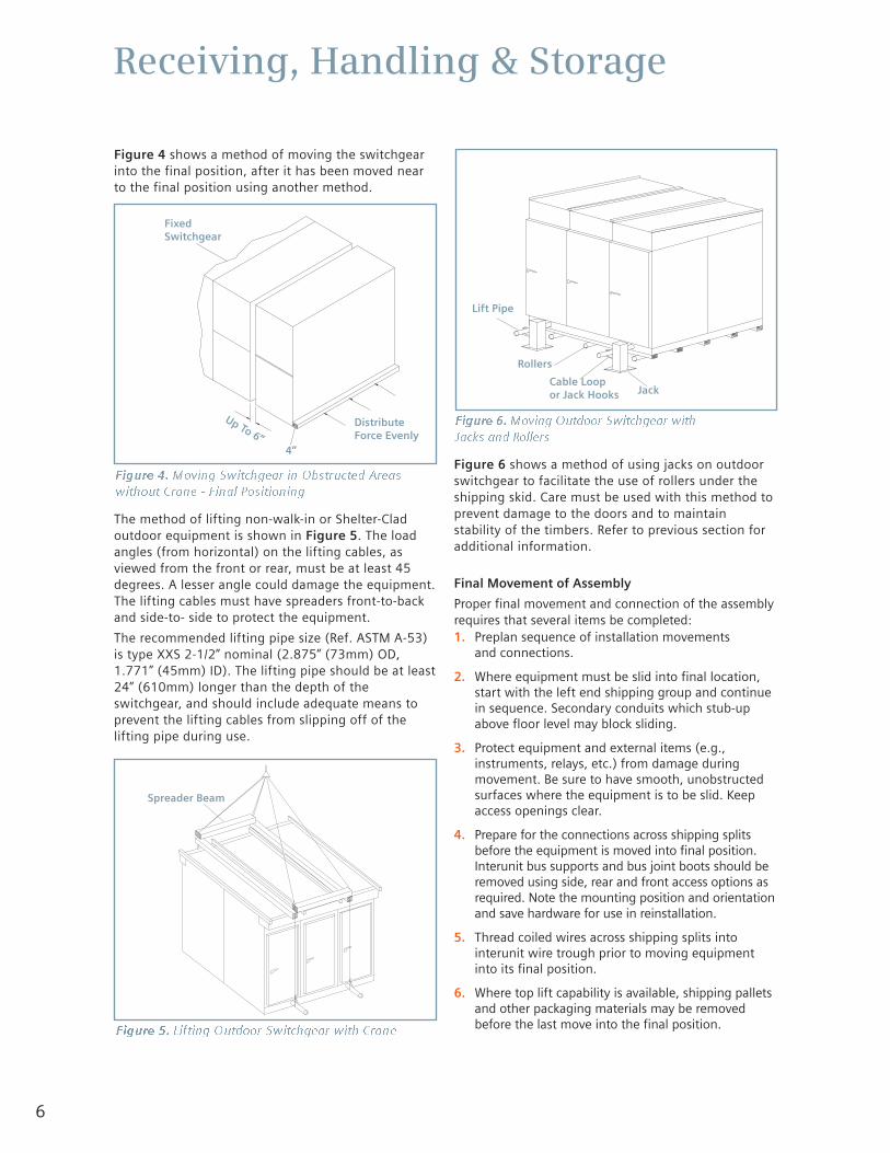
Figure 3 shows a method of using jacks on indoorswitchgear to facilitate the use of rollers under theshipping skid. Care must be used to prevent damage toinstruments, relays, and devices, and to maintain thestability of the timbers.
Remove rollers and lower the switchgear carefully. Leavewooden skids (when provided) in place during movingoperation until final location is reached.
Figure 2. Lifting Indoor Switchgear with Crane
Heavy weight.
Can result in death, serious personalinjury or property damage.
Observe all handling instructions in thisinstruction manual to prevent tipping ordropping of equipment.
Figure 3. Moving Switchgear with Jacks and Rollers
Lift Cable
Spreader Beams
Lift Beam
JackBeam
SupportTimbers
Jacks
Tie Down
Rollers
Banding
ProvideSuitableProtectionfor Corners
6
Receiving, Handling & Storage
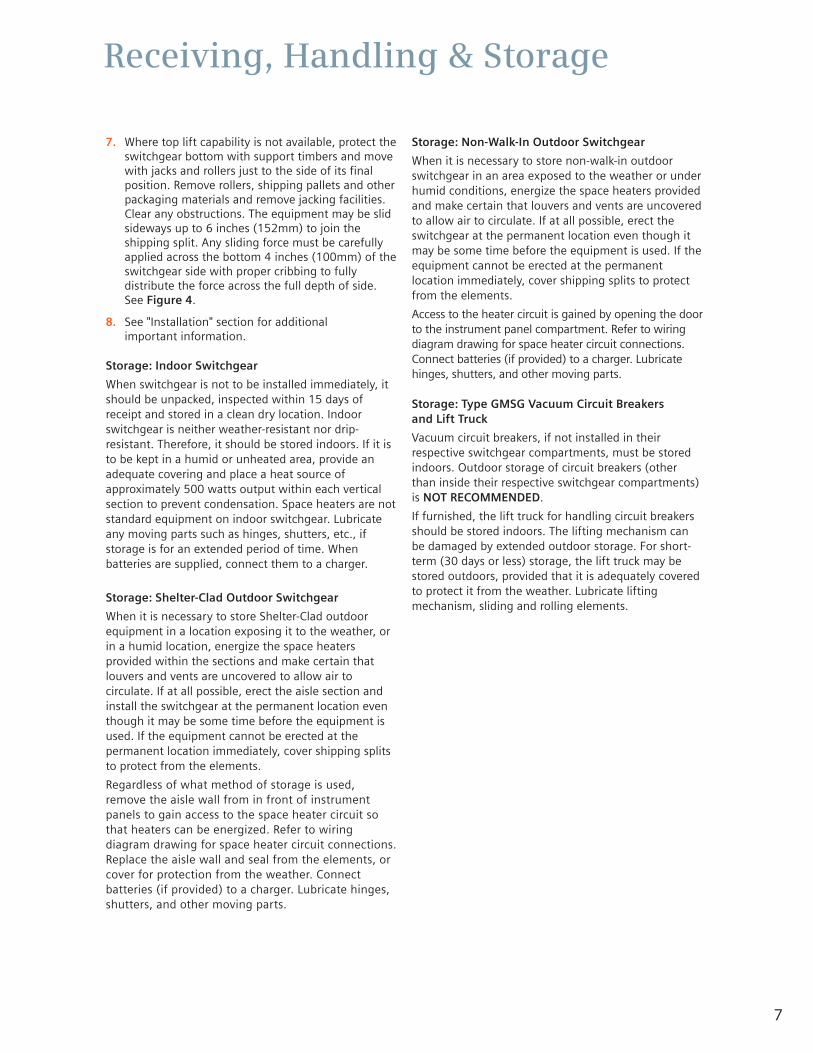
Figure 4 shows a method of moving the switchgearinto the final position, after it has been moved nearto the final position using another method.
The method of lifting non-walk-in or Shelter-Cladoutdoor equipment is shown in Figure 5. The loadangles (from horizontal) on the lifting cables, asviewed from the front or rear, must be at least 45degrees. A lesser angle could damage the equipment.The lifting cables must have spreaders front-to-backand side-to- side to protect the equipment.
The recommended lifting pipe size (Ref. ASTM A-53)is type XXS 2-1/2” nominal (2.875” (73mm) OD,1.771” (45mm) ID). The lifting pipe should be at least24” (610mm) longer than the depth of theswitchgear, and should include adequate means toprevent the lifting cables from slipping off of thelifting pipe during use.
Figure 6 shows a method of using jacks on outdoorswitchgear to facilitate the use of rollers under theshipping skid. Care must be used with this method toprevent damage to the doors and to maintainstability of the timbers. Refer to previous section foradditional information.
Final Movement of Assembly
Proper final movement and connection of the assemblyrequires that several items be completed:1. Preplan sequence of installation movements
and connections.
2. Where equipment must be slid into final location,start with the left end shipping group and continuein sequence. Secondary conduits which stub-upabove floor level may block sliding.
3. Protect equipment and external items (e.g.,instruments, relays, etc.) from damage duringmovement. Be sure to have smooth, unobstructedsurfaces where the equipment is to be slid. Keepaccess openings clear.
4. Prepare for the connections across shipping splitsbefore the equipment is moved into final position.Interunit bus supports and bus joint boots should beremoved using side, rear and front access options asrequired. Note the mounting position and orientationand save hardware for use in reinstallation.
5. Thread coiled wires across shipping splits intointerunit wire trough prior to moving equipmentinto its final position.
6. Where top lift capability is available, shipping palletsand other packaging materials may be removedbefore the last move into the final position.
Figure 4. Moving Switchgear in Obstructed Areaswithout Crane - Final Positioning
Figure 5. Lifting Outdoor Switchgear with Crane
Figure 6. Moving Outdoor Switchgear withJacks and Rollers
FixedSwitchgear
DistributeForce Evenly
Spreader Beam
Jack
Lift Pipe
Rollers
Cable Loopor Jack Hooks
Up To 6”4”
7
Receiving, Handling & Storage
7. Where top lift capability is not available, protect theswitchgear bottom with support timbers and movewith jacks and rollers just to the side of its finalposition. Remove rollers, shipping pallets and otherpackaging materials and remove jacking facilities.Clear any obstructions. The equipment may be slidsideways up to 6 inches (152mm) to join theshipping split. Any sliding force must be carefullyapplied across the bottom 4 inches (100mm) of theswitchgear side with proper cribbing to fullydistribute the force across the full depth of side.See Figure 4.
8. See "Installation" section for additional important information.
Storage: Indoor Switchgear
When switchgear is not to be installed immediately, itshould be unpacked, inspected within 15 days ofreceipt and stored in a clean dry location. Indoorswitchgear is neither weather-resistant nor drip-resistant. Therefore, it should be stored indoors. If it isto be kept in a humid or unheated area, provide anadequate covering and place a heat source ofapproximately 500 watts output within each verticalsection to prevent condensation. Space heaters are notstandard equipment on indoor switchgear. Lubricateany moving parts such as hinges, shutters, etc., ifstorage is for an extended period of time. Whenbatteries are supplied, connect them to a charger.
Storage: Shelter-Clad Outdoor Switchgear
When it is necessary to store Shelter-Clad outdoorequipment in a location exposing it to the weather, orin a humid location, energize the space heatersprovided within the sections and make certain thatlouvers and vents are uncovered to allow air tocirculate. If at all possible, erect the aisle section andinstall the switchgear at the permanent location eventhough it may be some time before the equipment isused. If the equipment cannot be erected at thepermanent location immediately, cover shipping splitsto protect from the elements.
Regardless of what method of storage is used,remove the aisle wall from in front of instrumentpanels to gain access to the space heater circuit sothat heaters can be energized. Refer to wiringdiagram drawing for space heater circuit connections.Replace the aisle wall and seal from the elements, orcover for protection from the weather. Connectbatteries (if provided) to a charger. Lubricate hinges,shutters, and other moving parts.
Storage: Non-Walk-In Outdoor Switchgear
When it is necessary to store non-walk-in outdoorswitchgear in an area exposed to the weather or underhumid conditions, energize the space heaters providedand make certain that louvers and vents are uncoveredto allow air to circulate. If at all possible, erect theswitchgear at the permanent location even though itmay be some time before the equipment is used. If theequipment cannot be erected at the permanentlocation immediately, cover shipping splits to protectfrom the elements.
Access to the heater circuit is gained by opening the doorto the instrument panel compartment. Refer to wiringdiagram drawing for space heater circuit connections.Connect batteries (if provided) to a charger. Lubricatehinges, shutters, and other moving parts.
Storage: Type GMSG Vacuum Circuit Breakers and Lift Truck
Vacuum circuit breakers, if not installed in theirrespective switchgear compartments, must be storedindoors. Outdoor storage of circuit breakers (otherthan inside their respective switchgear compartments)is NOT RECOMMENDED.
If furnished, the lift truck for handling circuit breakersshould be stored indoors. The lifting mechanism canbe damaged by extended outdoor storage. For short-term (30 days or less) storage, the lift truck may bestored outdoors, provided that it is adequately coveredto protect it from the weather. Lubricate liftingmechanism, sliding and rolling elements.
8
Installation
Preparation for Installation
Prior to installation of switchgear, study this instructionmanual and the switchgear drawings, such as generalarrangement, three-line diagram, schematic diagrams,wiring diagrams, installation instruction drawing, panelarrangement and panel arrangement bill of material,nameplate engraving list, and accessories drawing.Special attention should be given to the foundationinformation contained in this manual as well as theinformation provided on the equipment drawings. Be sure that the foundation conforms to therequirements described in this manual and the general arrangement drawing.
Foundation-General Requirements
Prior to installation of the switchgear, careful design,planning and construction of the foundation or baseon which the switchgear will rest must be made. Athorough analysis and careful construction mayalleviate many problems at the time of installation, andduring operation. It is important that a true and levelsurface be provided, capable of supporting the weightof the switchgear and other related equipment.
If the switchgear cannot be lowered over conduitsbecause of headroom or other restrictions, conduitcouplings may be grouted in flush with foundation, andconduit nipples added after the switchgear is in place.
Conduits should be capped during construction toprevent entry of dirt, moisture and vermin.
All sill channels, bed plates, shims and anchoring hardwareare furnished by purchaser unless covered by contract.
Indoor Foundations
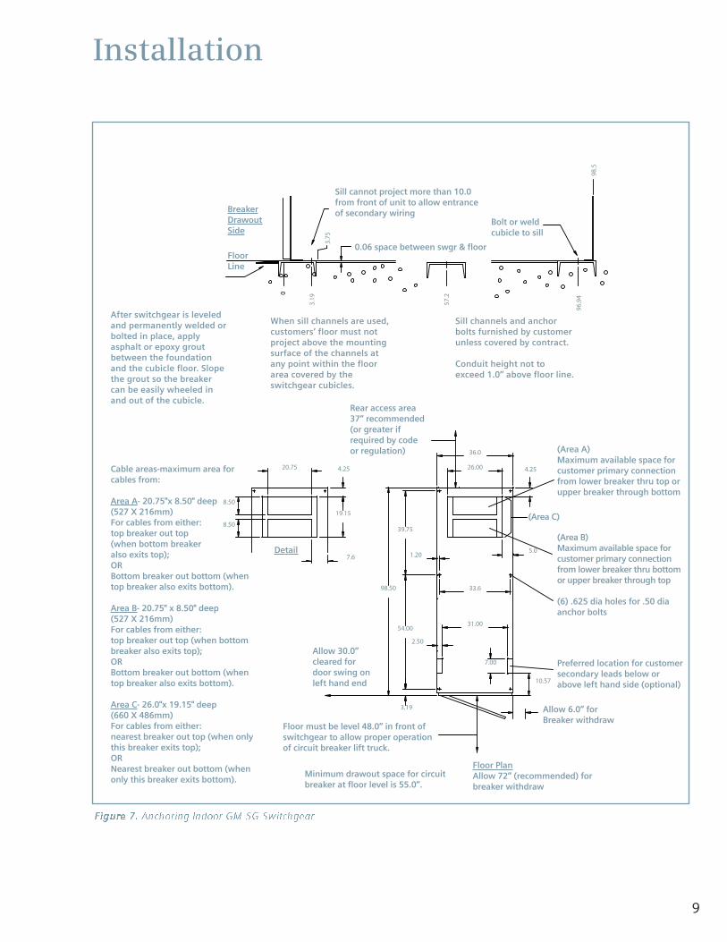
As it is difficult to obtain a true and level floor on aconcrete slab, it is highly recommended that 4”(minimum) sill channels be grouted into the floor asshown in Figure 7. The surface of the sills should beslightly above floor level. The surfaces of the sills mustbe level and in the same horizontal plane within 1/16”(1.6mm). There should be no projection above thisplane within the area covered by the switchgear. If thefloor or sills do not meet this requirement, it will benecessary to use shims when installing the switchgearon the mounting surface.
Figure 7 illustrates the location for sill channels foranchoring indoor switchgear. Cubicles may beanchored to sills by use of 1/2” (or 12mm) diameteranchor bolts, or welded in position.
Outdoor Foundations
Whichever type of foundation is used (e.g., concrete slab,sill channels, piers or pilings), it must have smooth andlevel surfaces. Surfaces supporting the switchgear mustbe in the same horizontal plane within 1/16” (1.6mm). Ifthese conditions are not met, it will be necessary to useshims when installing the switchgear.
For outdoor switchgear, support shall be provided ateach end and at the side of every second cubicle, sothat the span between supports does not exceed 36”(914mm). Refer to Figures 8 and 10, and theswitchgear general arrangement drawing for locationsof support and anchoring points. If pilings are used,the diameter is to be determined by purchaser,;however, they should not be less than 12” (305mm)diameter for sufficient contact, room for anchor bolts,and grouting in of bed plates (if used). All shippingsplits must be properly supported.
Any conduits which are installed in concrete must beperpendicular to switchgear mounting surface.Conduits should extend a minimum of 6-3/4”(171mm) to a maximum of 7-1/2” (190mm) abovemounting surface. This will allow the conduit toenter the cubicle and exclude entry of water androdents. Exception: If switchgear will be throat-connected to a power transformer, see “InstallingSwitchgear with Throat Connection to PowerTransformer” for restrictions on height of conduitsfor both primary and secondary conduits.
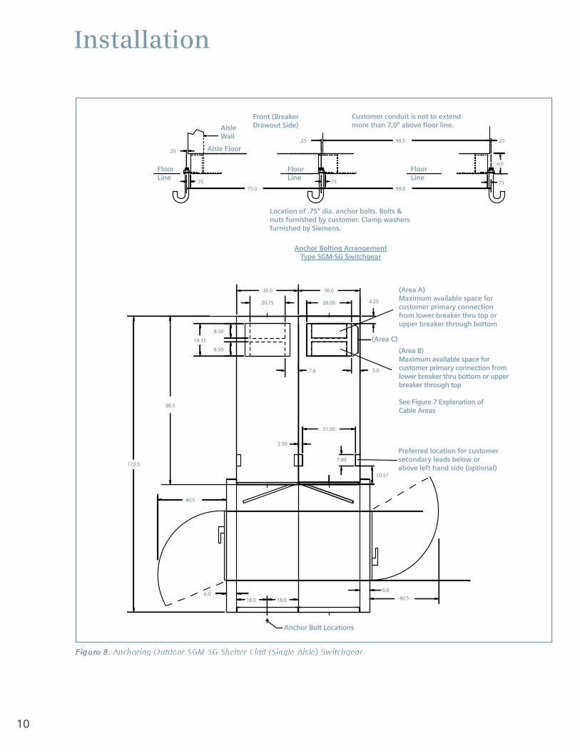
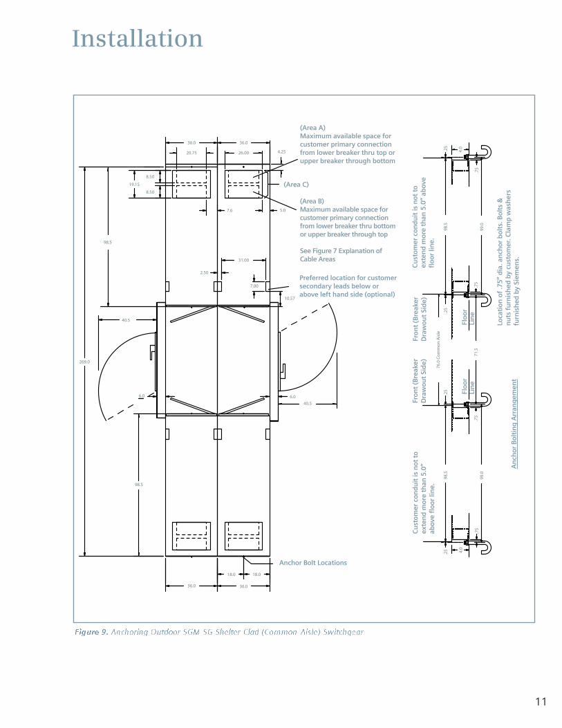
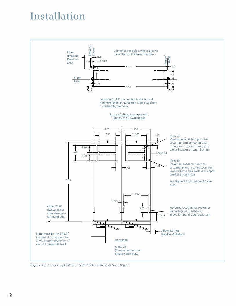
Figures 8-9 show the method of anchoring outdoorShelter-Clad (walk-in) switchgear, and Figure 10 shows themethod of anchoring outdoor non-walk-in switchgear.
Important: In the switchgear primary entrance area,steel reinforcing rods or mesh in concrete must not passthrough the space shown on the general arrangementdrawing, even though cored or bored holes in concretemay miss rods or mesh. A single phase of a systemshould not be encircled by ferrous metals.
Installation
9
3.75
0
3.19
57.2
96.9
4
98.5
36.0
4.25
19.15
4.25
8.50
8.50
20.75 26.00
5.0
33.6
7.6
3.19
1.20
54.00
39.75
98.50
2.50
31.00
7.00
10.57
Figure 7. Anchoring Indoor GM-SG Switchgear
After switchgear is leveledand permanently welded orbolted in place, applyasphalt or epoxy groutbetween the foundationand the cubicle floor. Slopethe grout so the breakercan be easily wheeled inand out of the cubicle.
Cable areas-maximum area forcables from:
Area A- 20.75"x 8.50" deep(527 X 216mm)For cables from either:top breaker out top (when bottom breaker also exits top);ORBottom breaker out bottom (whentop breaker also exits bottom).
Area B- 20.75" x 8.50" deep(527 X 216mm)For cables from either:top breaker out top (when bottombreaker also exits top);ORBottom breaker out bottom (whentop breaker also exits bottom).
Area C- 26.0"x 19.15" deep(660 X 486mm)For cables from either:nearest breaker out top (when onlythis breaker exits top);ORNearest breaker out bottom (whenonly this breaker exits bottom).
(Area A)Maximum available space forcustomer primary connectionfrom lower breaker thru top orupper breaker through bottom
(Area B)Maximum available space forcustomer primary connectionfrom lower breaker thru bottomor upper breaker through top
(6) .625 dia holes for .50 diaanchor bolts
Preferred location for customersecondary leads below orabove left hand side (optional)
Allow 6.0” for Breaker withdraw
Floor PlanAllow 72” (recommended) forbreaker withdraw
Minimum drawout space for circuitbreaker at floor level is 55.0”.
Allow 30.0”cleared fordoor swing onleft hand end
Rear access area37” recommended(or greater ifrequired by codeor regulation)
Sill cannot project more than 10.0from front of unit to allow entranceof secondary wiring
Floor must be level 48.0” in front ofswitchgear to allow proper operationof circuit breaker lift truck.
Detail
BreakerDrawoutSide
FloorLine
0.06 space between swgr & floor
Bolt or weldcubicle to sill
When sill channels are used,customers’ floor must notproject above the mountingsurface of the channels atany point within the floorarea covered by theswitchgear cubicles.
Sill channels and anchorbolts furnished by customerunless covered by contract.
Conduit height not toexceed 1.0” above floor line.
(Area C)
10
Installation
.25
.75.75
6.0
.2598.5
99.075.0.75
.25
173.5
36.0
26.00 4.25
5.0
2.50
31.00
7.00
10.57
98.5
36.0
20.75
19.15
8.50
8.50
7.6
18.0 18.06.0
40.5
40.5
6.0
Figure 8. Anchoring Outdoor SGM-SG Shelter-Clad (Single-Aisle) Switchgear
(Area A)Maximum available space forcustomer primary connectionfrom lower breaker thru top orupper breaker through bottom
(Area B)Maximum available space forcustomer primary connection fromlower breaker thru bottom or upperbreaker through top
See Figure 7 Explanation of Cable Areas
Preferred location for customersecondary leads below orabove left hand side (optional)
Customer conduit is not to extendmore than 7.0” above floor line.
Location of .75” dia. anchor bolts. Bolts &nuts furnished by customer. Clamp washersfurnished by Siemens.
Anchor Bolting ArrangementType SGM-SG Switchgear
FloorLine
FloorLine
FloorLine
Anchor Bolt Locations
AisleWall
Front (BreakerDrawout Side)
Aisle Floor
(Area C)
11
Installation
98.5
18.018.0
36.0
269.0
10.57
31.00
2.50
4.25
36.0
98.5
6.0
40.5
7.00
5.0
26.00
36.0
20.75
36.0
19.15
8.50
8.50
.75
.75
.25
4.0
.25
.75
71.5
76.0
Co
mm
on
Ais
le
99.0
98.5
.25
99.0
98.5
.25
4.0
40.5
6.0
7.6
.75
Figure 9. Anchoring Outdoor SGM-SG Shelter-Clad (Common-Aisle) Switchgear
(Area A)Maximum available space forcustomer primary connectionfrom lower breaker thru top orupper breaker through bottom
(Area B)Maximum available space forcustomer primary connectionfrom lower breaker thru bottomor upper breaker through top
See Figure 7 Explanation ofCable Areas
Preferred location for customersecondary leads below orabove left hand side (optional)
Cu
sto
mer
co
nd
uit
is n
ot t
oex
ten
d m
ore
th
an 5
.0”
abov
e fl
oo
r lin
e.
Cu
sto
mer
co
nd
uit
is n
ot t
oex
ten
d m
ore
th
an 5
.0”
abov
efl
oo
r lin
e.
Fro
nt
(Bre
aker
Dra
wo
ut
Sid
e)Fr
on
t (B
reak
erD
raw
ou
t Si
de)
Loca
tio
n o
f .7
5” d
ia. a
nch
or
bo
lts.
Bo
lts
&n
uts
fu
rnis
hed
by
cust
om
er. C
lam
p w
ash
ers
furn
ish
ed b
y Si
emen
s.A
nch
or
Bo
ltin
g A
rran
gem
ent
Flo
or
Lin
eFl
oo
rLi
ne
Anchor Bolt Locations
(Area C)
12
Installation
10.57
7.00
31.00
2.50
36.0
20.75
36.0
19.15
7.65.0
4.2526.00
.50
6.0
.75
1.0
4.63
1.12 Panel
97.25.75
8.50
8.50
95.75
98.5
Figure 10. Anchoring Outdoor OGM-SG Non-Walk-in Switchgear
(Area A)Maximum available space forcustomer primary connectionfrom lower breaker thru top orupper breaker through bottom
(Area B)Maximum available space forcustomer primary connection fromlower breaker thru bottom or upperbreaker through top
See Figure 7 Explanation of CableAreas
Preferred location for customersecondary leads below orabove left hand side (optional)
Allow 6.0” forBreaker Withdraw
Allow 30.0”clearance fordoor swing onleft hand end.
Floor must be level 48.0”in front of switchgear toallow proper operation ofcircuit breaker lift truck.
Floor Plan
Allow 76”(Recommended) forBreaker Withdraw
Location of .75” dia. anchor bolts. Bolts &nuts furnished by customer. Clamp washersfurnished by Siemens.
Anchor Bolting ArrangementType SGM-SG Switchgear
FloorLine
(Area C)
Fro
nt
of
Fram
e
Rea
r o
fFr
ame
Front(BreakerDrawoutSide)
Customer conduit is not to extendmore than 7.0” above floor line.
13
Installation
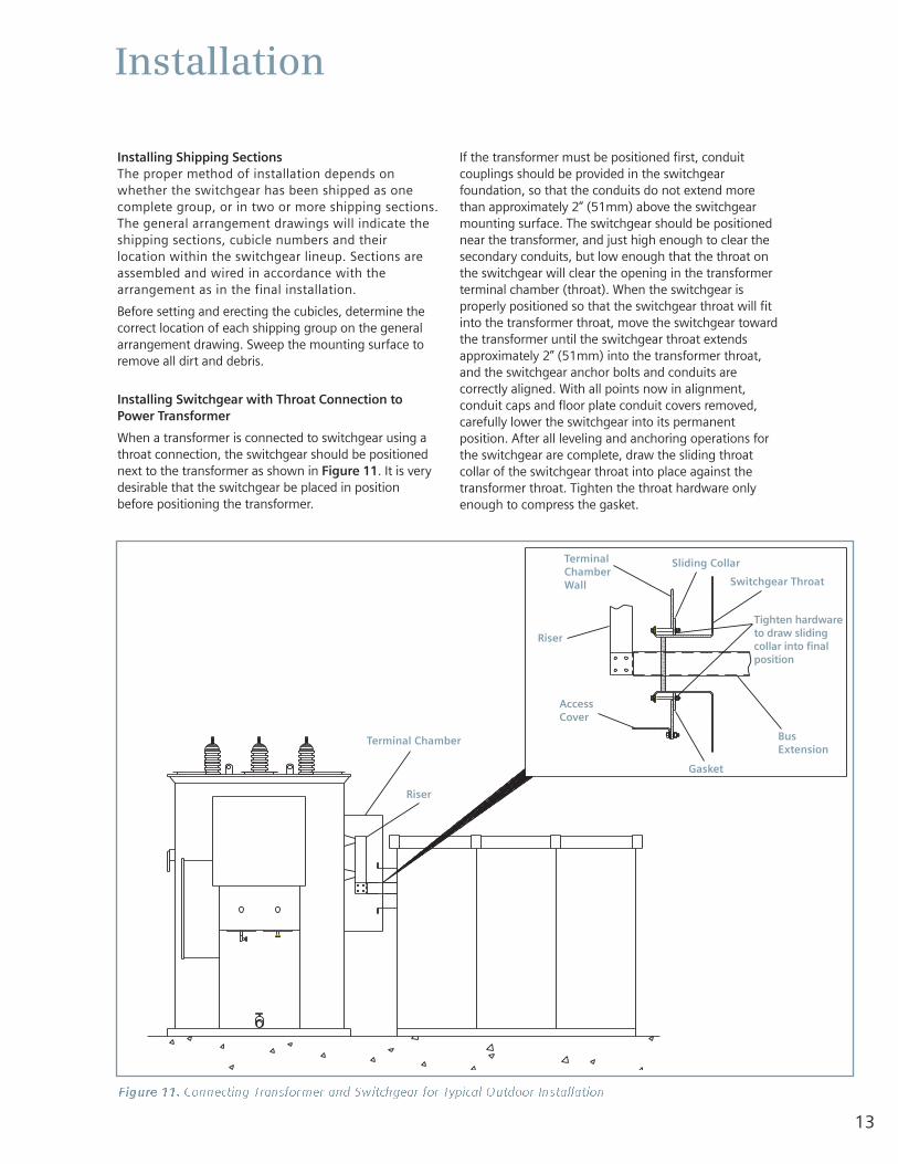
Installing Shipping SectionsThe proper method of installation depends onwhether the switchgear has been shipped as onecomplete group, or in two or more shipping sections.The general arrangement drawings will indicate theshipping sections, cubicle numbers and theirlocation within the switchgear lineup. Sections areassembled and wired in accordance with thearrangement as in the final installation.
Before setting and erecting the cubicles, determine thecorrect location of each shipping group on the generalarrangement drawing. Sweep the mounting surface toremove all dirt and debris.
Installing Switchgear with Throat Connection toPower Transformer
When a transformer is connected to switchgear using athroat connection, the switchgear should be positionednext to the transformer as shown in Figure 11. It is verydesirable that the switchgear be placed in positionbefore positioning the transformer.
If the transformer must be positioned first, conduitcouplings should be provided in the switchgearfoundation, so that the conduits do not extend morethan approximately 2” (51mm) above the switchgearmounting surface. The switchgear should be positionednear the transformer, and just high enough to clear thesecondary conduits, but low enough that the throat onthe switchgear will clear the opening in the transformerterminal chamber (throat). When the switchgear isproperly positioned so that the switchgear throat will fitinto the transformer throat, move the switchgear towardthe transformer until the switchgear throat extendsapproximately 2” (51mm) into the transformer throat,and the switchgear anchor bolts and conduits arecorrectly aligned. With all points now in alignment,conduit caps and floor plate conduit covers removed,carefully lower the switchgear into its permanentposition. After all leveling and anchoring operations forthe switchgear are complete, draw the sliding throatcollar of the switchgear throat into place against thetransformer throat. Tighten the throat hardware onlyenough to compress the gasket.
Figure 11. Connecting Transformer and Switchgear for Typical Outdoor Installation
Terminal Chamber
TerminalChamberWall
Riser
Riser
AccessCover
Gasket
Sliding Collar
Switchgear Throat
BusExtension
Tighten hardwareto draw slidingcollar into finalposition
14
Installation
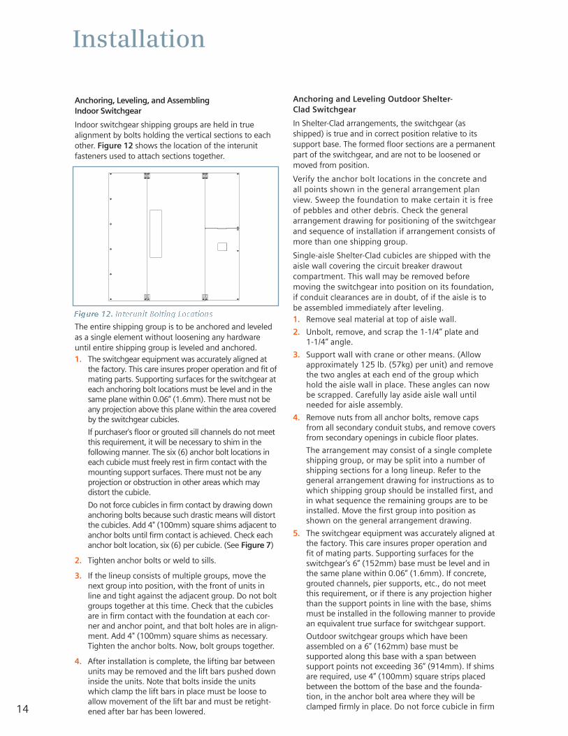
Anchoring, Leveling, and Assembling Indoor Switchgear
Indoor switchgear shipping groups are held in truealignment by bolts holding the vertical sections to eachother. Figure 12 shows the location of the interunitfasteners used to attach sections together.
The entire shipping group is to be anchored and leveledas a single element without loosening any hardwareuntil entire shipping group is leveled and anchored.1. The switchgear equipment was accurately aligned at
the factory. This care insures proper operation and fit ofmating parts. Supporting surfaces for the switchgear ateach anchoring bolt locations must be level and in thesame plane within 0.06” (1.6mm). There must not beany projection above this plane within the area coveredby the switchgear cubicles.
If purchaser's floor or grouted sill channels do not meetthis requirement, it will be necessary to shim in thefollowing manner. The six (6) anchor bolt locations ineach cubicle must freely rest in firm contact with themounting support surfaces. There must not be anyprojection or obstruction in other areas which maydistort the cubicle.
Do not force cubicles in firm contact by drawing downanchoring bolts because such drastic means will distortthe cubicles. Add 4" (100mm) square shims adjacent toanchor bolts until firm contact is achieved. Check eachanchor bolt location, six (6) per cubicle. (See Figure 7)
2. Tighten anchor bolts or weld to sills.
3. If the lineup consists of multiple groups, move thenext group into position, with the front of units inline and tight against the adjacent group. Do not boltgroups together at this time. Check that the cubiclesare in firm contact with the foundation at each cor-ner and anchor point, and that bolt holes are in align-ment. Add 4" (100mm) square shims as necessary.Tighten the anchor bolts. Now, bolt groups together.
4. After installation is complete, the lifting bar betweenunits may be removed and the lift bars pushed downinside the units. Note that bolts inside the unitswhich clamp the lift bars in place must be loose toallow movement of the lift bar and must be retight-ened after bar has been lowered.
Anchoring and Leveling Outdoor Shelter-Clad Switchgear
In Shelter-Clad arrangements, the switchgear (asshipped) is true and in correct position relative to itssupport base. The formed floor sections are a permanentpart of the switchgear, and are not to be loosened ormoved from position.
Verify the anchor bolt locations in the concrete andall points shown in the general arrangement planview. Sweep the foundation to make certain it is freeof pebbles and other debris. Check the generalarrangement drawing for positioning of the switchgearand sequence of installation if arrangement consists ofmore than one shipping group.
Single-aisle Shelter-Clad cubicles are shipped with theaisle wall covering the circuit breaker drawoutcompartment. This wall may be removed beforemoving the switchgear into position on its foundation,if conduit clearances are in doubt, of if the aisle is tobe assembled immediately after leveling.1. Remove seal material at top of aisle wall.
2. Unbolt, remove, and scrap the 1-1/4” plate and 1-1/4” angle.
3. Support wall with crane or other means. (Allowapproximately 125 lb. (57kg) per unit) and removethe two angles at each end of the group whichhold the aisle wall in place. These angles can nowbe scrapped. Carefully lay aside aisle wall untilneeded for aisle assembly.
4. Remove nuts from all anchor bolts, remove capsfrom all secondary conduit stubs, and remove coversfrom secondary openings in cubicle floor plates.
The arrangement may consist of a single completeshipping group, or may be split into a number ofshipping sections for a long lineup. Refer to thegeneral arrangement drawing for instructions as towhich shipping group should be installed first, andin what sequence the remaining groups are to beinstalled. Move the first group into position asshown on the general arrangement drawing.
5. The switchgear equipment was accurately aligned atthe factory. This care insures proper operation andfit of mating parts. Supporting surfaces for theswitchgear’s 6” (152mm) base must be level and inthe same plane within 0.06” (1.6mm). If concrete,grouted channels, pier supports, etc., do not meetthis requirement, or if there is any projection higherthan the support points in line with the base, shimsmust be installed in the following manner to providean equivalent true surface for switchgear support.
Outdoor switchgear groups which have beenassembled on a 6” (162mm) base must besupported along this base with a span betweensupport points not exceeding 36” (914mm). If shimsare required, use 4” (100mm) square strips placedbetween the bottom of the base and the founda-tion, in the anchor bolt area where they will beclamped firmly in place. Do not force cubicle in firm
Figure 12. Interunit Bolting Locations
15
Installation
contact by drawing down anchoring bolts as suchdrastic means will distort cubicles.
6. Add clamp washers and nuts to anchor bolts andtighten securely.
7. Check all circuit breaker compartments for freemovement of the shutters.
8. Move the next group into position. The front edgeof the cubicle base should be in line with those ofthe previously installed group. This will insure agood fit with the aisle floor plates. Make certainthat the end of the group being installed is tightlyagainst the previously installed group. Repeat steps5, 6, and 7 and install all shipping split hardware.
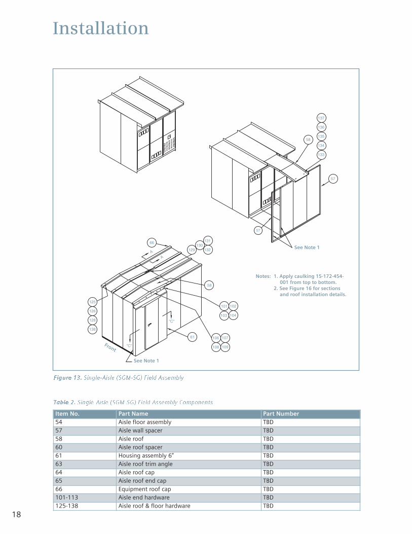
Assembly of Single-Aisle Shelter-Clad Switchgear
Figure 13 illustrates the assembly of single-aisleShelter-Clad switchgear, and Table 2 lists the standardcomponents supplied. The item numbers in the tableare used in all instructions pertaining to this procedure.
Assemble as follows:1. Temporarily support the aisle wall assembly in its
permanent position as shown in the generalarrangement drawing.
2. Put roof covers in place to hold top of aisle wall inplace. Do not tighten hardware.
3. Align the ends of the aisle wall, aisle channel andswitchgear. Place floor plate in position between theswitchgear and wall. Install each set next to the endposition between the switchgear and the wall. Withfloor plate set tightly against the switchgear floorplates, bolt floor plates in position. Tighten anchorbolts to secure channel locations.
4. With roof cover hardware loose, plumb front wall andtighten attaching hardware.
5. Install all floor plates.
6. Caulk aisle walls.
Set door assemblies in place. Bolt the door to theaisle wall and to the side plate of the cubicle.
7. Put all roof covers in place and bolt to the adjoiningroof cover with 3/8” hardware.
8. Set roof channels over roof cover joints. Bolt to clipswelded to roof with retainer nuts.
9. Drill cable cover to suit conduit installation. Bolt thecover in place.
10. Mount aisle conduit, switches, receptacle and wire tothe junction boxes. See conduit arrangement.
11. If equipment consists of more than one shippinggroup, caulk each vertical shipping split at the backof the switchgear with metal filler provided.
Note: Place lift truck (if supplied) for upper cell circuitbreakers inside the aisle enclosure before installation ofthe last door assembly to the enclosure. The lift truck iswider and higher than the hinged aisle door opening,which prevents convenient entrance of the lift truck ifthe door assemblies are in place.
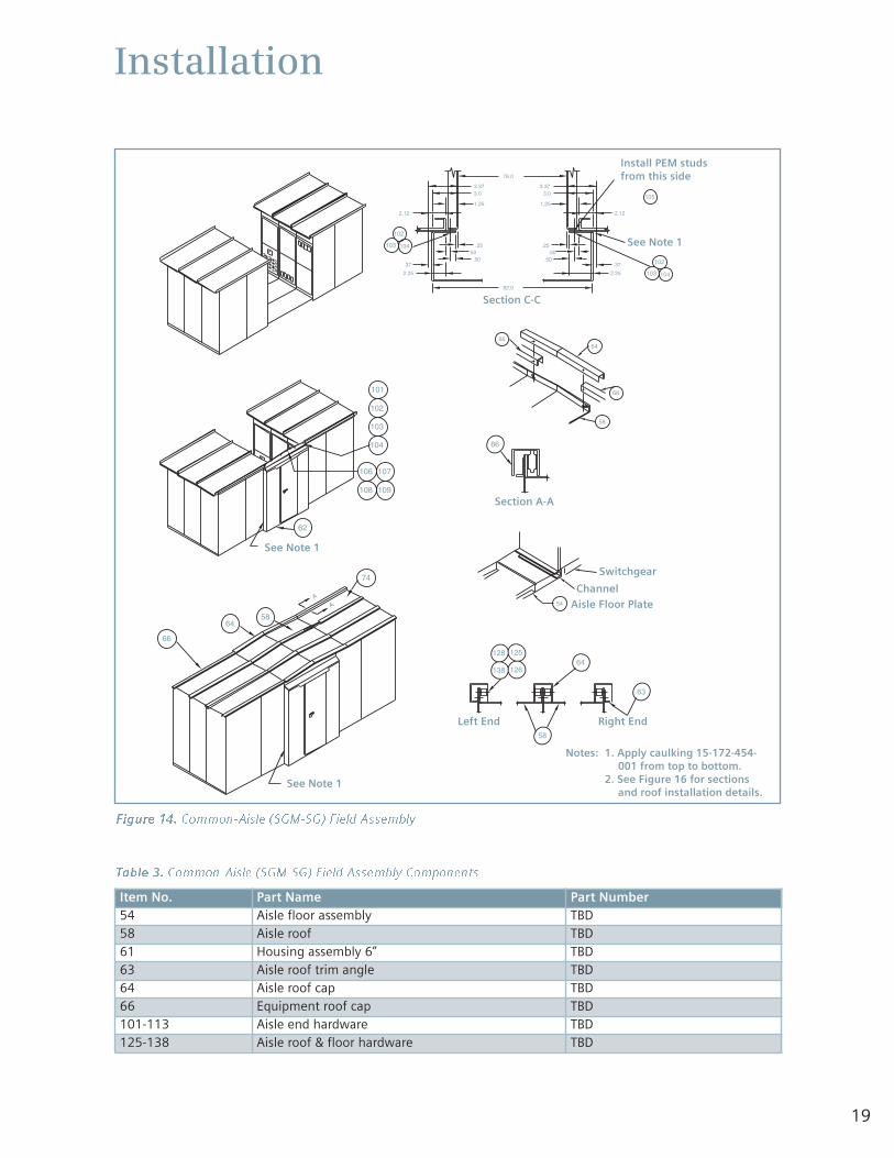
Assembly of Common-Aisle Shelter-Clad Switchgear
Figure 14 illustrates the assembly of common-aisleShelter-Clad switchgear, and Table 3 lists the standardcomponents supplied. The item numbers in the table areused in all instructions pertaining to this procedure.
Assemble as follows:1. Install all floor plates.
2. Caulk at joints.
3. Raise door assemblies into place. Bolt doors to sideplates of cubicles.
4. Mount aisle conduit, switches, receptacle and wire tothe junction boxes. See conduit arrangement.
5. Place roof decks in position and fasten with bolts provided.
6. Fasten the roof decks together with 3/8” hardware.
7. Set channel-shaped covers over the joints of roof decks and bolt to clips welded to roof withretainer nuts.
8. Tighten all bolts to complete assembly.
9. Drill cable cover to suit conduit. Bolt the cover in place.
10. If equipment consists of more than one shippinggroup, caulk each vertical shipping split at the backof the switchgear with metal filler provided.
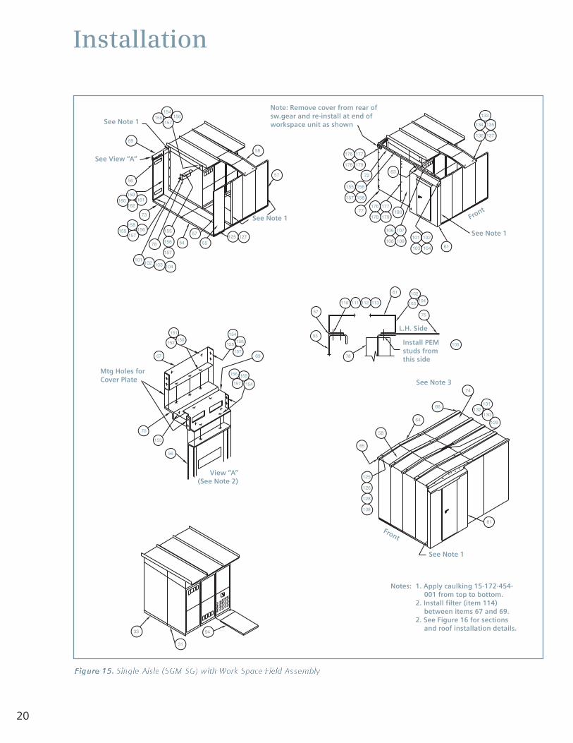
Assembly of Single-Aisle Shelter-Clad Switchgearwith Work Space
Figure 15 illustrates the assembly of single-aisle Shelter-Clad switchgear with an attached Work Space area, andTable 4 lists the standard components supplied. Theitem numbers in the table are used in all instructionspertaining to this procedure.
Assemble as follows:1. Mount aisle end plate at the end opposite the
work space.
2. Move aisle wall to its permanent location as indicatedon the general arrangement drawing.
3. Mount the end plate and proceed.
4. Put the work space floor plate base in position asindicated.
5. Assemble aisle walls. See general arrangementdrawing for location of special panels for fans, etc.Apply caulking at the joints of the wall sections.
6. Bolt work space rear plates (item 56) together, in amanner similar to the aisle wall sections, and thenbolt to the switchgear unit.
Note: Place lift truck (if supplied) for upper cell circuitbreakers inside the aisle enclosure before installation ofthe last door assembly to the enclosure. The lift truck iswider and higher than the hinged aisle door opening,which prevents convenient entrance of the lift truck ifthe door assemblies are in place.
16
Installation
4. Disconnect aisle conduit.
5. Remove all hardware securing the side plate to theswitchgear frame and hardware securing aisle endplate to the aisle wall. It may be necessary to tap aknife blade down the vertical seam between the aislewall and the end plate to cut the caulking. Removethe side plates from both switchgear and aisle.
6. The lineup is now ready for installation of the new unitor units. If the foundation was carefully constructedthere should be no problems with lineup of the baseor matching the level of existing equipment.
7. With new units in true alignment with existing andproperly leveled, bolt units together with 1/2”hardware provided.
8. Run aisle wiring from the terminal block in existingend units, through the barrier and header to thejunction box area.
9. Mount other parts removed from existing equipmentand caulk all external seams with metal filler.
10. Make all electrical connections as instructed ininstallation manual or shown on drawings.
11. Caulk each vertical split at back of switchgearbetween the existing equipment and the newaddition with metal filler. Replace bus compartmentbarriers and install back plates.
Anchoring, Leveling, and Assembling ConventionalOutdoor (Non-Walk-In) Switchgear
In conventional outdoor (non-walk-in) arrangements theswitchgear (as shipped) is true and in correct positionrelative to its support base.The formed floor basesections are a permanent part of the switchgear, and arenot to be loosened or moved from position.
Verify the anchor bolt locations in the concrete and allpoints shown in the general arrangement plan view.Sweep the foundation to make certain it is free of pebblesand other debris. Check the general arrangementdrawing for positioning of the switchgear and sequenceof installation if arrangement consists of more than oneshipping group.1. Remove nuts from all anchor bolts, remove caps from
all secondary conduit stubs, and remove covers fromsecondary openings in cubicle floor plates.
The arrangement may consist of a single completeshipping group, or may be split into a number ofshipping sections for a long lineup. Refer to thegeneral arrangement drawing for instructions as towhich shipping group should be installed first, and inwhat sequence the remaining groups are to beinstalled. Move the first group into position as shownon the general arrangement drawing.
2. The switchgear equipment was accurately aligned atthe factory. This care insures proper operation and fitof mating parts. Supporting surfaces for theswitchgear’s 6” (152mm) base must be level and inthe same plane within 0.06” (1.6mm). If concrete,
7. Caulk at joints.
8. Install end plate and attach to switchgear.
9. Install aisle floor plates in the same manner as forsingle-aisle layouts.
10. Install roof support (item 78) from cubicles to end ofwork space area.
11. Put all roof decks in place and bolt to the top of theend plate and to the roof support. Leave hardwarefinger tight until step 13 is complete.
12. Fasten roof decks together with 3/8” hardware.
13. Mount trim angle. Tighten all hardware.
14. Set roof channels over roof deck joints, bolt to clipswelded to roof with retainer nuts.
15. Mount aisle conduit, switches, receptacle and wire tothe junction boxes. See conduit arrangement.
16. If equipment consists of more than one shippinggroup, caulk each vertical shipping split at the backof the switchgear with metal filler provided.
Expanding Length of Existing Shelter-Clad Switchgearby Addition of Units
The new extended foundation, be it slab, pier or pilings,must be constructed in the same careful manner asdescribed under “Outdoor Foundations”. The newfoundation must be level and in the same plane within0.06” (1.6mm) as the existing foundation.
Certain items will be removed from the existinginstallation as described in the following instructions.Remove these items carefully and store them for re-mounting in the expanded setup.
1. Remove the channel-shaped covers over roof jointsfrom both aisle and switchgear unit.
2. Remove the trim angle from the outer edge of theroof deck.
3. Remove the back plates to provide access to thehardware securing the end cover. Remove the endcover with associated parts and save for later re-installation.
Note: Place lift truck (if supplied) for upper cell circuitbreakers inside the aisle enclosure before installation ofthe last door assembly to the enclosure. The lift truck iswider and higher than the hinged aisle door opening,which prevents convenient entrance of the lift truck ifthe door assemblies are in place.
Hazardous voltage and high-speed moving parts.
Will cause death, serious personal injury,and property damage.
Do not work on energized equipment. Alwaysde-energize and ground the equipment beforeworking on the equipment.
17
Installation
grouted channels, pier supports, etc., do not meetthis requirement, or if there is any projection higherthan the support points in line with the base, shimsmust be installed in the following manner to providean equivalent true surface for switchgear support.
Outdoor switchgear groups which have beenassembled on a 6” (162mm) base must be supportedalong this base with a span between support pointsnot exceeding 36” (914mm). If shims are required,use 4” (100mm) square strips placed between thebottom of the base and the foundation, in theanchor bolt area where they will be clamped firmly inplace. Do not force cubicle in firm contact by drawingdown anchoring bolts as such drastic means willdistort cubicles.
3. Add clamp washers and nuts to anchor bolts andtighten securely.
4. Check all circuit breaker compartments for freemovement of the shutters.
5. Move the next group into position. The front edge ofthe cubicle base should be in line with those of thepreviously installed group. This will insure a good fitwith the aisle floor plates. Make certain that the endof the group being installed is tightly against thepreviously installed group. Repeat steps 3, 4, and 5and install all shipping split hardware.
Expanding Length of Existing Conventional Outdoor(Non-Walk-In) Switchgear by Addition of Units
Expanding the length of existing conventional outdoorswitchgear by field addition of units should be handledin the same manner as Shelter-Clad switchgear with theexception that there is no aisle with which to beconcerned. Follow the instructions given under“Expanding Length of Existing Shelter-Clad Switchgear by Addition of Units”. However, note that only roofchannels, bus compartment barriers, and end platesneed to be removed on conventional switchgear.
18
Installation
NOTES: 1. Apply Caulking 15-172-454-001
AA
"C"
"C"
58
133
134
135
136
137
57
57
129130
131
132
125
126
128
138
66
61
58
106 107
109108
104
102101
103
Figure 13. Single-Aisle (SGM-SG) Field Assembly
Table 2. Single-Aisle (SGM-SG) Field Assembly Components
Item No. Part Name Part Number54 Aisle floor assembly TBD57 Aisle wall spacer TBD58 Aisle roof TBD60 Aisle roof spacer TBD61 Housing assembly 6” TBD63 Aisle roof trim angle TBD64 Aisle roof cap TBD65 Aisle roof end cap TBD66 Equipment roof cap TBD101-113 Aisle end hardware TBD125-138 Aisle roof & floor hardware TBD
Notes: 1. Apply caulking 15-172-454-001 from top to bottom.
2. See Figure 16 for sectionsand roof installation details.
See Note 1
See Note 1
Front
19
Installation
.25.50
.50
2.25
.37
2.12
1.25
3.03.37 3.37
3.0
1.25
.50
.25
2.25
.37
.50
76.0
82.0
AA
2.12
62
106 107
109108
102
104
101
103
66
64
74
58
66
138
128
126
125
63
64
58
58
64
66
66
54
104
102
103
104103
102
105
Figure 14. Common-Aisle (SGM-SG) Field Assembly
Table 3. Common-Aisle (SGM-SG) Field Assembly Components
Item No. Part Name Part Number54 Aisle floor assembly TBD58 Aisle roof TBD61 Housing assembly 6” TBD63 Aisle roof trim angle TBD64 Aisle roof cap TBD66 Equipment roof cap TBD101-113 Aisle end hardware TBD125-138 Aisle roof & floor hardware TBD
Notes: 1. Apply caulking 15-172-454-001 from top to bottom.
2. See Figure 16 for sectionsand roof installation details.
See Note 1
See Note 1
Section C-C
Install PEM studsfrom this side
See Note 1
Section A-A
Switchgear
Channel
Left End Right End
Aisle Floor Plate
20
Installation
128
138
126
125
66
61
130
129
131132
74
58
64
65
125 12757
55
157156155
158
56
54
101
155
102
156
104103
157
78
58
57
5433
31
136
134 135
137
133
179178
177176
158157
156155
178 179
176 177
72
106 107
109108
104103
102101
61
110 111 112 113
61
57
55
78
102
103104
75
105
159160 161
162
69
7377
63
56
154
155156
157
67
150152
151
155
154
156
157
153
70
180
69
157156
154155
Figure 15. Single-Aisle (SGM-SG) with Work Space Field Assembly
Notes: 1. Apply caulking 15-172-454-001 from top to bottom.
2. Install filter (item 114)between items 67 and 69.
2. See Figure 16 for sectionsand roof installation details.
See Note 1
Note: Remove cover from rear ofsw.gear and re-install at end ofworkspace unit as shown
See Note 1
See Note 1
See Note 3
View “A”(See Note 2)
L.H. Side
Install PEMstuds fromthis side
Mtg Holes forCover Plate
See Note 1
See View “A”
Front
Front

21
Installation
Table 4. Single-Aisle (SGM-SG) With Work Field Assembly Components
Item No. Part Name Part Number54 Aisle floor assembly TBD55 Wall panel assembly (aisle) TBD56 Wall panel assembly (workspace) TBD57 Aisle wall spacer TBD58 Aisle roof TBD61 Housing assembly 6” TBD63 Aisle roof trim angle TBD64 Aisle roof cap TBD65 Aisle roof end cap TBD66 Equipment roof cap TBD67 Header assembly (rear) TBD69 Roof support (rear) TBD70 Vent panel (rear) TBD71 Roof trim angle (left end) TBD72 Roof trim angle (right end) TBD73 Workspace floor assembly TBD74 Roof panel TBD75 End trim front (left end) TBD76 End trim front (right end) TBD77 End trim rear (left & right) TBD78 End trim front (left end) TBD101-113 Aisle end hardware TBD125-138 Aisle roof & floor hardware TBD
22
Installation
82.0
79.0
.50.50
.25
.37
2.75
1.25
3.03.37
2.75
2.25
2.12
58
64
63
66
54
125 127
60
58
54103 104
102
57
110 111
112 113
105
66
58
65
64
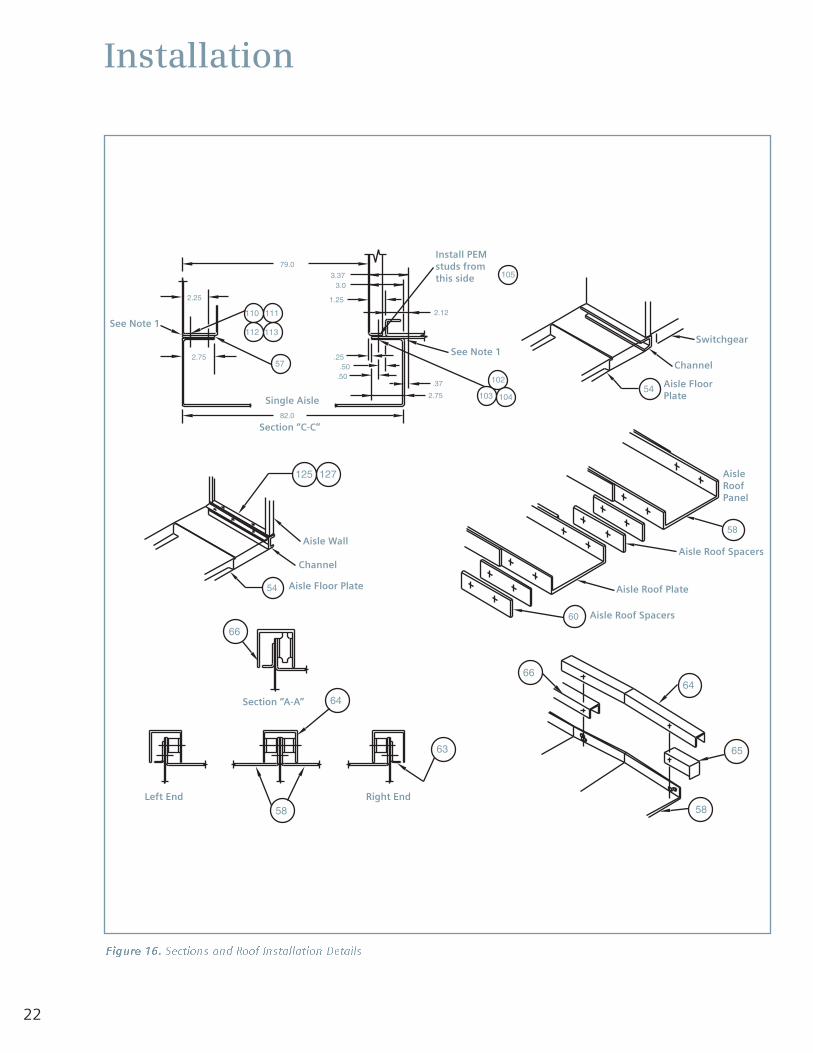
Figure 16. Sections and Roof Installation Details
See Note 1
See Note 1Switchgear
Channel
Aisle FloorPlate
Channel
Aisle Wall
Aisle Floor Plate Aisle Roof Plate
Aisle Roof Spacers
Aisle Roof Spacers
Right EndLeft End
AisleRoofPanel
Single Aisle
Section “C-C”
Section “A-A”
Install PEMstuds fromthis side
23
Electrical Connections
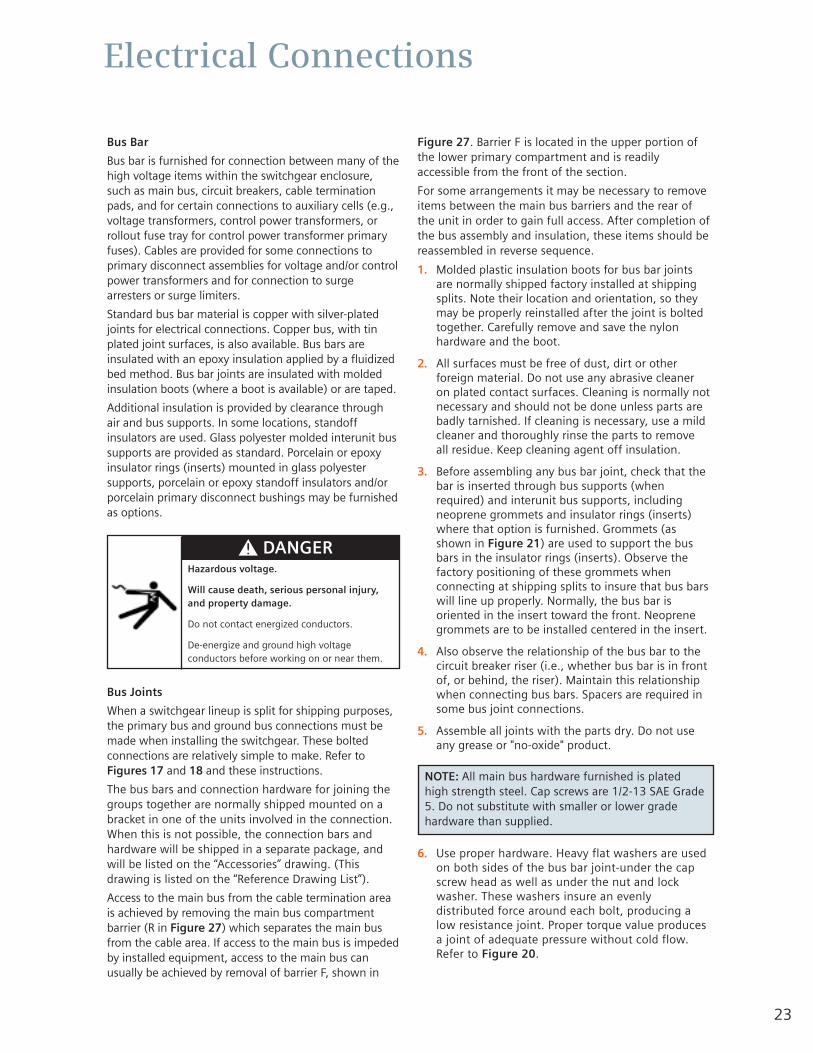
Bus Bar
Bus bar is furnished for connection between many of thehigh voltage items within the switchgear enclosure,such as main bus, circuit breakers, cable terminationpads, and for certain connections to auxiliary cells (e.g.,voltage transformers, control power transformers, orrollout fuse tray for control power transformer primaryfuses). Cables are provided for some connections toprimary disconnect assemblies for voltage and/or controlpower transformers and for connection to surgearresters or surge limiters.
Standard bus bar material is copper with silver-platedjoints for electrical connections. Copper bus, with tinplated joint surfaces, is also available. Bus bars areinsulated with an epoxy insulation applied by a fluidizedbed method. Bus bar joints are insulated with moldedinsulation boots (where a boot is available) or are taped.
Additional insulation is provided by clearance throughair and bus supports. In some locations, standoffinsulators are used. Glass polyester molded interunit bussupports are provided as standard. Porcelain or epoxyinsulator rings (inserts) mounted in glass polyestersupports, porcelain or epoxy standoff insulators and/orporcelain primary disconnect bushings may be furnishedas options.
Bus Joints
When a switchgear lineup is split for shipping purposes,the primary bus and ground bus connections must bemade when installing the switchgear. These boltedconnections are relatively simple to make. Refer toFigures 17 and 18 and these instructions.
The bus bars and connection hardware for joining thegroups together are normally shipped mounted on abracket in one of the units involved in the connection.When this is not possible, the connection bars andhardware will be shipped in a separate package, andwill be listed on the “Accessories” drawing. (Thisdrawing is listed on the “Reference Drawing List”).
Access to the main bus from the cable termination areais achieved by removing the main bus compartmentbarrier (R in Figure 27) which separates the main busfrom the cable area. If access to the main bus is impededby installed equipment, access to the main bus canusually be achieved by removal of barrier F, shown in
Figure 27. Barrier F is located in the upper portion ofthe lower primary compartment and is readilyaccessible from the front of the section.
For some arrangements it may be necessary to removeitems between the main bus barriers and the rear ofthe unit in order to gain full access. After completion ofthe bus assembly and insulation, these items should bereassembled in reverse sequence.
1. Molded plastic insulation boots for bus bar jointsare normally shipped factory installed at shippingsplits. Note their location and orientation, so theymay be properly reinstalled after the joint is boltedtogether. Carefully remove and save the nylonhardware and the boot.
2. All surfaces must be free of dust, dirt or otherforeign material. Do not use any abrasive cleaneron plated contact surfaces. Cleaning is normally notnecessary and should not be done unless parts arebadly tarnished. If cleaning is necessary, use a mildcleaner and thoroughly rinse the parts to removeall residue. Keep cleaning agent off insulation.
3. Before assembling any bus bar joint, check that thebar is inserted through bus supports (whenrequired) and interunit bus supports, includingneoprene grommets and insulator rings (inserts)where that option is furnished. Grommets (asshown in Figure 21) are used to support the busbars in the insulator rings (inserts). Observe thefactory positioning of these grommets whenconnecting at shipping splits to insure that bus barswill line up properly. Normally, the bus bar isoriented in the insert toward the front. Neoprenegrommets are to be installed centered in the insert.
4. Also observe the relationship of the bus bar to thecircuit breaker riser (i.e., whether bus bar is in frontof, or behind, the riser). Maintain this relationshipwhen connecting bus bars. Spacers are required insome bus joint connections.
5. Assemble all joints with the parts dry. Do not useany grease or "no-oxide" product.
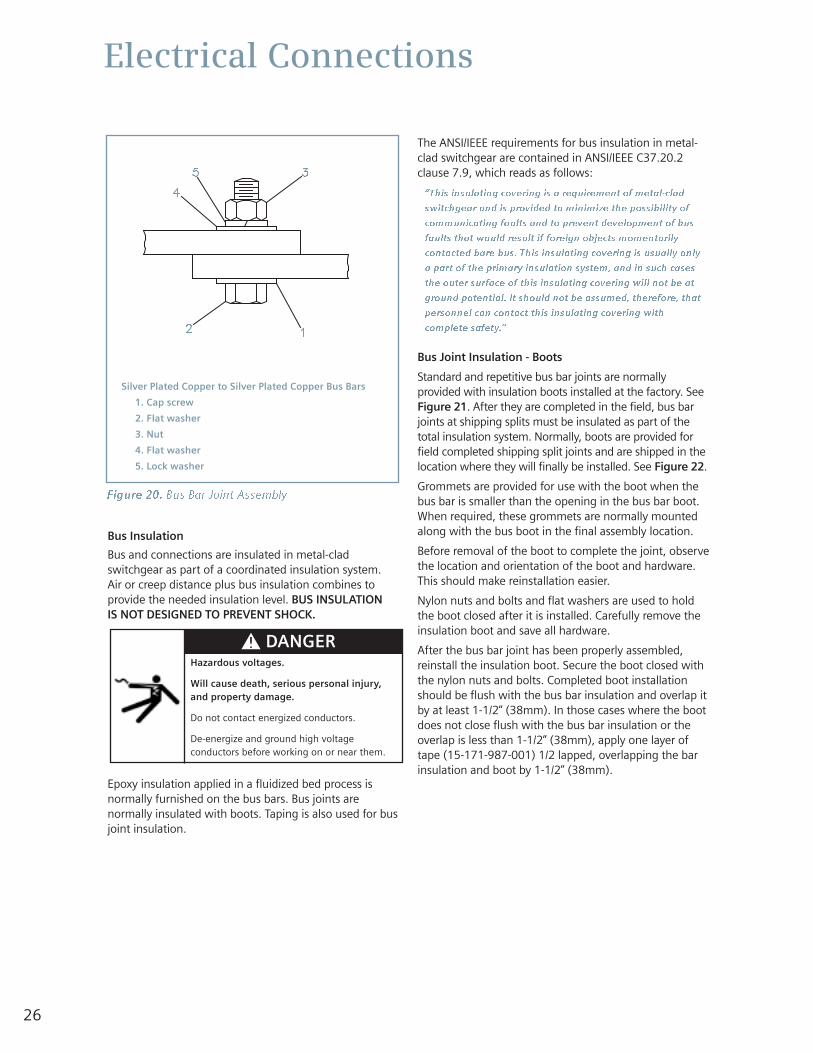
6. Use proper hardware. Heavy flat washers are usedon both sides of the bus bar joint-under the capscrew head as well as under the nut and lockwasher. These washers insure an evenlydistributed force around each bolt, producing alow resistance joint. Proper torque value producesa joint of adequate pressure without cold flow.Refer to Figure 20.
Hazardous voltage.
Will cause death, serious personal injury,and property damage.
Do not contact energized conductors.
De-energize and ground high voltageconductors before working on or near them.
NOTE: All main bus hardware furnished is platedhigh strength steel. Cap screws are 1/2-13 SAE Grade5. Do not substitute with smaller or lower gradehardware than supplied.
24
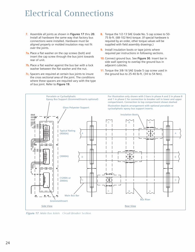
7. Assemble all joints as shown in Figures 17 thru 20.Install all hardware the same way that factory busconnections were installed. Hardware must bealigned properly or molded insulation may not fitover the joints.
7a. Place a flat washer on the cap screws (bolt) andinsert the cap screw through the bus joint towardsrear of unit.
7b. Place a flat washer against the bus bar with a lockwasher between the flat washer and the nut.
7c. Spacers are required at certain bus joints to insurethe cross sectional area of the joint. The conditionswhere these spacers are required vary with the typeof bus joint. Refer to Figure 19.
8. Torque the 1/2-13 SAE Grade No. 5 cap screws to 50-75 lb-ft. (68-102 Nm) torque. (If special hardware isrequired by an order, other torque values will besupplied with field assembly drawings.)
9. Install insulation boots or tape joints whererequired per instructions in following sections.
10. Connect ground bus. See Figure 30. Insert bar inside wall opening to overlap the ground bus inadjacent cubicles.
11. Torque the 3/8-16 SAE Grade 5 cap screw used inthe ground bus to 25-40 lb-ft. (34 to 54 Nm).
Electrical Connections
ABC
A
B
C
A
B
C
ABC
Figure 17. Main Bus Joints - Circuit Breaker Section
Porcelain or CycloaliphaticEpoxy Bus Support (Grommet/inserts optional)
For illustration only shown with 3 bars in phase A and 2 in phase Band 1 in phase C for connection to breaker cell in lower and uppercompartment. Connection to top compartment shown dashed
Illustration depicts arrangement with optional porcelain orcycloaliphatic epoxy bus support inserts.Glass Polyester Support
Insulation Boot
Bus RiserGrommet/Insert
Typical Rating(4000A)
(3000A)
(1200A or2000A)
Side View Rear View
Main Bus Bar
25
Electrical Connections
C
B
A
B
A
C
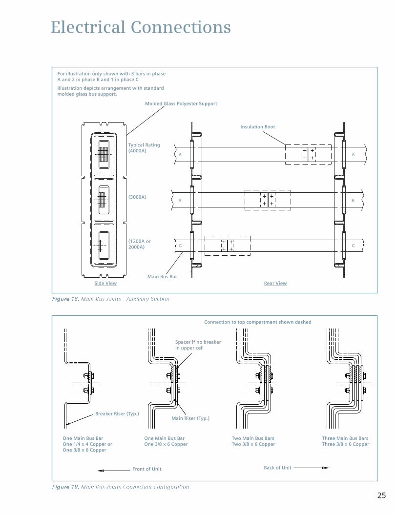
Figure 18. Main Bus Joints - Auxiliary Section
Figure 19. Main Bus Joints Connection Configuration
For illustration only shown with 3 bars in phaseA and 2 in phase B and 1 in phase C
Illustration depicts arrangement with standardmolded glass bus support.
Molded Glass Polyester Support
Insulation Boot
Main Bus Bar
Breaker Riser (Typ.)Main Riser (Typ.)
Spacer if no breakerin upper cell
Connection to top compartment shown dashed
Front of Unit
One Main Bus BarOne 1/4 x 4 Copper orOne 3/8 x 6 Copper
One Main Bus BarOne 3/8 x 6 Copper
Two Main Bus BarsTwo 3/8 x 6 Copper
Three Main Bus BarsThree 3/8 x 6 Copper
Back of Unit
Typical Rating(4000A)
(3000A)
(1200A or2000A)
Side View Rear View
26
Electrical Connections
A - Tin Plated Aluminum to Tin Plated AluminumBus Bars or
B - Tin Plated Aluminum to Silver Plated Copper
1. Cap Screw2. Flat Washer3. "Belleville" Washer 3.1 Before Torquing
AB C
3.1 3.2 6
5
4
12
Legend
3.2 After Torquing4. Nut
4. Nut
C - Silver Plated Copper to Silver Plated Copper
6. Lock Washer5. Flat Washer
2. Flat Washer1. Cap Screw
Bus Bars
Bus Bars
1 2
Figure 20. Bus Bar Joint Assembly
Bus Insulation
Bus and connections are insulated in metal-cladswitchgear as part of a coordinated insulation system. Air or creep distance plus bus insulation combines toprovide the needed insulation level. BUS INSULATION IS NOT DESIGNED TO PREVENT SHOCK.
Epoxy insulation applied in a fluidized bed process isnormally furnished on the bus bars. Bus joints arenormally insulated with boots. Taping is also used for busjoint insulation.
The ANSI/IEEE requirements for bus insulation in metal-clad switchgear are contained in ANSI/IEEE C37.20.2clause 7.9, which reads as follows:
“This insulating covering is a requirement of metal-clad
switchgear and is provided to minimize the possibility of
communicating faults and to prevent development of bus
faults that would result if foreign objects momentarily
contacted bare bus. This insulating covering is usually only
a part of the primary insulation system, and in such cases
the outer surface of this insulating covering will not be at
ground potential. It should not be assumed, therefore, that
personnel can contact this insulating covering with
complete safety.”
Bus Joint Insulation - Boots
Standard and repetitive bus bar joints are normallyprovided with insulation boots installed at the factory. SeeFigure 21. After they are completed in the field, bus barjoints at shipping splits must be insulated as part of thetotal insulation system. Normally, boots are provided forfield completed shipping split joints and are shipped in thelocation where they will finally be installed. See Figure 22.
Grommets are provided for use with the boot when thebus bar is smaller than the opening in the bus bar boot.When required, these grommets are normally mountedalong with the bus boot in the final assembly location.
Before removal of the boot to complete the joint, observethe location and orientation of the boot and hardware.This should make reinstallation easier.
Nylon nuts and bolts and flat washers are used to holdthe boot closed after it is installed. Carefully remove theinsulation boot and save all hardware.
After the bus bar joint has been properly assembled,reinstall the insulation boot. Secure the boot closed withthe nylon nuts and bolts. Completed boot installationshould be flush with the bus bar insulation and overlap itby at least 1-1/2“ (38mm). In those cases where the bootdoes not close flush with the bus bar insulation or theoverlap is less than 1-1/2” (38mm), apply one layer oftape (15-171-987-001) 1/2 lapped, overlapping the barinsulation and boot by 1-1/2” (38mm).
Hazardous voltages.
Will cause death, serious personal injury,and property damage.
Do not contact energized conductors.
De-energize and ground high voltageconductors before working on or near them.
Silver Plated Copper to Silver Plated Copper Bus Bars
1. Cap screw
2. Flat washer
3. Nut
4. Flat washer
5. Lock washer
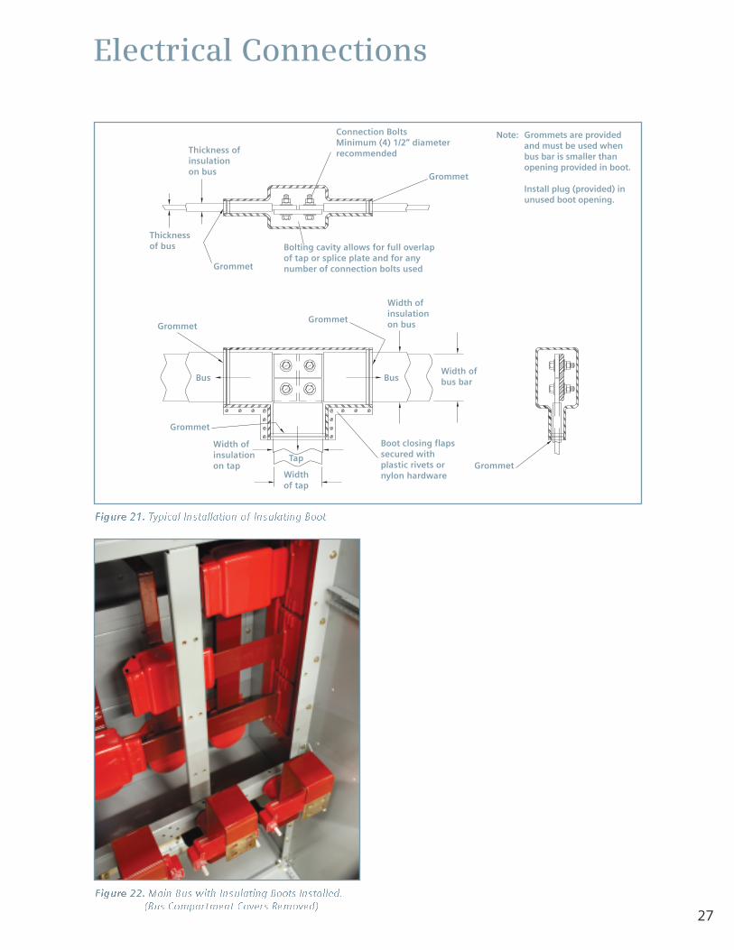
27
Electrical Connections
Figure 21. Typical Installation of Insulating Boot
Figure 22. Main Bus with Insulating Boots Installed.(Bus Compartment Covers Removed)
Connection BoltsMinimum (4) 1/2” diameterrecommendedThickness of
insulationon bus
Boot closing flapssecured withplastic rivets ornylon hardware
Thicknessof bus
BusWidth ofbus bar
Width ofinsulationon bus
Width ofinsulationon tap
Widthof tap
Tap
Bus
Grommet
Grommet
GrommetGrommet
Grommet
Grommet
Bolting cavity allows for full overlapof tap or splice plate and for anynumber of connection bolts used
Note: Grommets are providedand must be used whenbus bar is smaller thanopening provided in boot.
Install plug (provided) inunused boot opening.
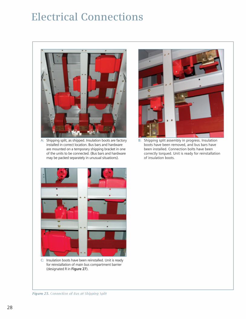
28
Electrical Connections
Figure 23. Connection of Bus at Shipping Split
A: Shipping split, as shipped. Insulation boots are factoryinstalled in correct location. Bus bars and hardwareare mounted on a temporary shipping bracket in oneof the units to be connected. (Bus bars and hardwaremay be packed separately in unusual situations).
C: Insulation boots have been reinstalled. Unit is readyfor reinstallation of main bus compartment barrier(designated R in Figure 27).
B: Shipping split assembly in progress. Insulationboots have been removed, and bus bars havebeen installed. Connection bolts have beencorrectly torqued. Unit is ready for reinstallationof insulation boots.
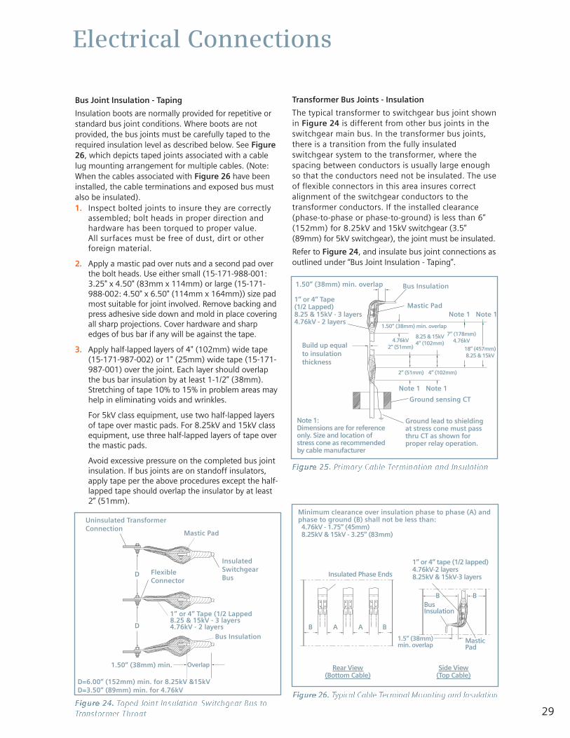
29
Electrical Connections
Bus Joint Insulation - Taping
Insulation boots are normally provided for repetitive orstandard bus joint conditions. Where boots are notprovided, the bus joints must be carefully taped to therequired insulation level as described below. See Figure26, which depicts taped joints associated with a cablelug mounting arrangement for multiple cables. (Note:When the cables associated with Figure 26 have beeninstalled, the cable terminations and exposed bus mustalso be insulated).1. Inspect bolted joints to insure they are correctly
assembled; bolt heads in proper direction andhardware has been torqued to proper value. All surfaces must be free of dust, dirt or otherforeign material.
2. Apply a mastic pad over nuts and a second pad overthe bolt heads. Use either small (15-171-988-001:3.25" x 4.50" (83mm x 114mm) or large (15-171-988-002: 4.50" x 6.50" (114mm x 164mm)) size padmost suitable for joint involved. Remove backing andpress adhesive side down and mold in place coveringall sharp projections. Cover hardware and sharpedges of bus bar if any will be against the tape.
3. Apply half-lapped layers of 4" (102mm) wide tape(15-171-987-002) or 1" (25mm) wide tape (15-171-987-001) over the joint. Each layer should overlapthe bus bar insulation by at least 1-1/2” (38mm).Stretching of tape 10% to 15% in problem areas mayhelp in eliminating voids and wrinkles.
For 5kV class equipment, use two half-lapped layersof tape over mastic pads. For 8.25kV and 15kV classequipment, use three half-lapped layers of tape overthe mastic pads.
Avoid excessive pressure on the completed bus jointinsulation. If bus joints are on standoff insulators,apply tape per the above procedures except the half-lapped tape should overlap the insulator by at least2” (51mm).
Transformer Bus Joints - Insulation
The typical transformer to switchgear bus joint shownin Figure 24 is different from other bus joints in theswitchgear main bus. In the transformer bus joints,there is a transition from the fully insulatedswitchgear system to the transformer, where thespacing between conductors is usually large enoughso that the conductors need not be insulated. The useof flexible connectors in this area insures correctalignment of the switchgear conductors to thetransformer conductors. If the installed clearance(phase-to-phase or phase-to-ground) is less than 6”(152mm) for 8.25kV and 15kV switchgear (3.5”(89mm) for 5kV switchgear), the joint must be insulated.
Refer to Figure 24, and insulate bus joint connections asoutlined under “Bus Joint Insulation - Taping”.
Figure 24. Taped Joint Insulation-Switchgear Bus toTransformer Throat
Figure 25. Primary Cable Termination and Insulation
Figure 26. Typical Cable Terminal Mounting and Insulation
InsulatedSwitchgearBus
Mastic Pad
Mastic Pad
Note 1 Note 1
Note 1 Note 1
1.50” (38mm) min.
Uninsulated TransformerConnection
D=6.00” (152mm) min. for 8.25kV &15kVD=3.50” (89mm) min. for 4.76kV
FlexibleConnector
1” or 4” Tape (1/2 Lapped8.25 & 15kV - 3 layers4.76kV - 2 layers
1” or 4” Tape (1/2 Lapped)8.25 & 15kV - 3 layers4.76kV - 2 layers
Ground lead to shieldingat stress cone must passthru CT as shown forproper relay operation.
Note 1:Dimensions are for referenceonly. Size and location ofstress cone as recommendedby cable manufacturer
1” or 4” tape (1/2 lapped)4.76kV-2 layers8.25kV & 15kV-3 layers
Minimum clearance over insulation phase to phase (A) andphase to ground (B) shall not be less than:4.76kV - 1.75” (45mm)8.25kV & 15kV - 3.25” (83mm)
B
B A A B
BusInsulation
MasticPad
Insulated Phase Ends
Side View(Top Cable)
Rear View(Bottom Cable)
1.5” (38mm)min. overlap
B
Build up equalto insulationthickness
Bus Insulation
Bus Insulation
Ground sensing CT
1.50” (38mm) min. overlap
1.50” (38mm) min. overlap7” (178mm)
4.76kV
18” (457mm)8.25 & 15kV
8.25 & 15kV4” (102mm)4.76kV
2” (51mm)
2” (51mm) 4” (102mm)
Overlap
D
D
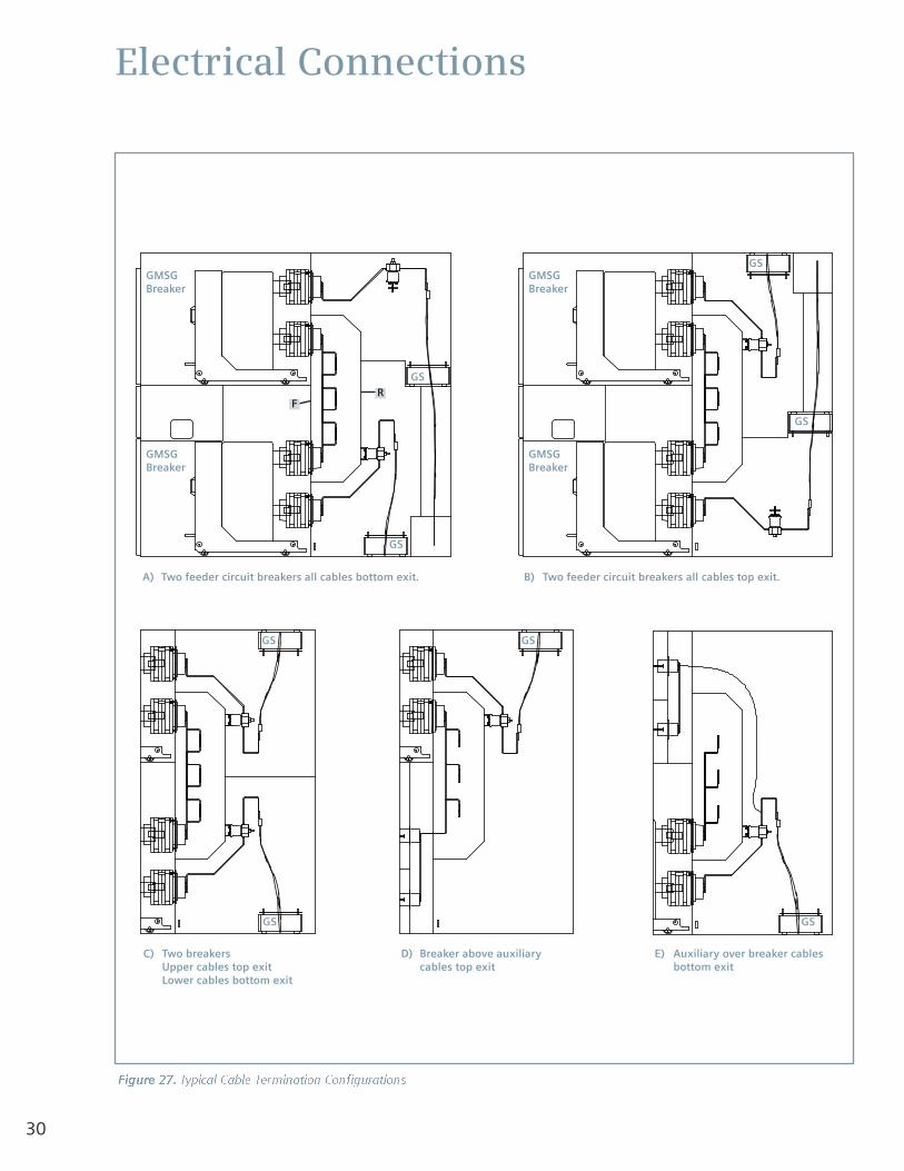
30
Electrical Connections
Figure 27. Typical Cable Termination Configurations
GMSGBreaker
GS
GS
GS
GS GS
GSGS
GS
GMSGBreaker
A) Two feeder circuit breakers all cables bottom exit. B) Two feeder circuit breakers all cables top exit.
C) Two breakersUpper cables top exitLower cables bottom exit
D) Breaker above auxiliarycables top exit
E) Auxiliary over breaker cablesbottom exit
GMSGBreaker
GMSGBreaker
FR
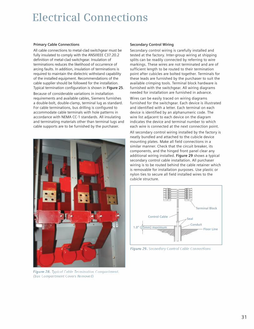
31
Electrical Connections
Primary Cable Connections
All cable connections to metal-clad switchgear must befully insulated to comply with the ANSI/IEEE C37.20.2definition of metal-clad switchgear. Insulation ofterminations reduces the likelihood of occurrence ofarcing faults. In addition, insulation of terminations isrequired to maintain the dielectric withstand capabilityof the installed equipment. Recommendations of thecable supplier should be followed for the installation.Typical termination configuration is shown in Figure 25.
Because of considerable variations in installationrequirements and available cables, Siemens furnishes a double-bolt, double-clamp, terminal lug as standard.For cable terminations, bus drilling is configured toaccommodate cable terminals with hole patterns inaccordance with NEMA CC-1 standards. All insulatingand terminating materials other than terminal lugs andcable supports are to be furnished by the purchaser.
Secondary Control Wiring
Secondary control wiring is carefully installed andtested at the factory. Inter-group wiring at shippingsplits can be readily connected by referring to wiremarkings. These wires are not terminated and are ofsufficient length to be routed to their terminationpoint after cubicles are bolted together. Terminals forthese leads are furnished by the purchaser to suit theavailable crimping tools. Terminal block hardware isfurnished with the switchgear. All wiring diagramsneeded for installation are furnished in advance.
Wires can be easily traced on wiring diagramsfurnished for the switchgear. Each device is illustratedand identified with a letter. Each terminal on eachdevice is identified by an alphanumeric code. Thewire list adjacent to each device on the diagramindicates the device and terminal number to whicheach wire is connected at the next connection point.
All secondary control wiring installed by the factory isneatly bundled and attached to the cubicle devicemounting plates. Make all field connections in asimilar manner. Check that the circuit breaker, itscomponents, and the hinged front panel clear anyadditional wiring installed. Figure 29 shows a typicalsecondary control cable installation. All purchaserwiring is to be routed behind the cable retainer whichis removable for installation purposes. Use plastic ornylon ties to secure all field installed wires to thecubicle structure.
Figure 28. Typical Cable Termination Compartment.(Bus Compartment Covers Removed)
Figure 29. Secondary Control Cable Connections
Control Cable
Terminal Block
Seal
Conduit
Floor Line1.0” (25mm) maximum
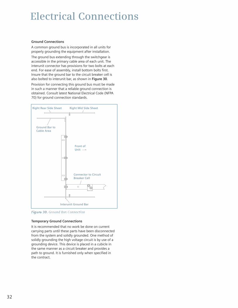
32
Electrical Connections
Ground Connections
A common ground bus is incorporated in all units forproperly grounding the equipment after installation.
The ground bus extending through the switchgear isaccessible in the primary cable area of each unit. Theinterunit connector has provisions for two bolts at eachend. For ease of assembly, install bottom bolts first.Insure that the ground bar to the circuit breaker cell isalso bolted to interunit bar, as shown in Figure 30.
Provision for connecting this ground bus must be madein such a manner that a reliable ground connection isobtained. Consult latest National Electrical Code (NFPA70) for ground connection standards.
Temporary Ground Connections
It is recommended that no work be done on currentcarrying parts until these parts have been disconnectedfrom the system and solidly grounded. One method ofsolidly grounding the high voltage circuit is by use of agrounding device. This device is placed in a cubicle inthe same manner as a circuit breaker and provides apath to ground. It is furnished only when specified inthe contract.
Figure 30. Ground Bus Connection
Right Rear Side Sheet
Ground Bar toCable Area
Front ofUnit
Connector to CircuitBreaker Cell
Interunit Ground Bar
Right Mid Side Sheet
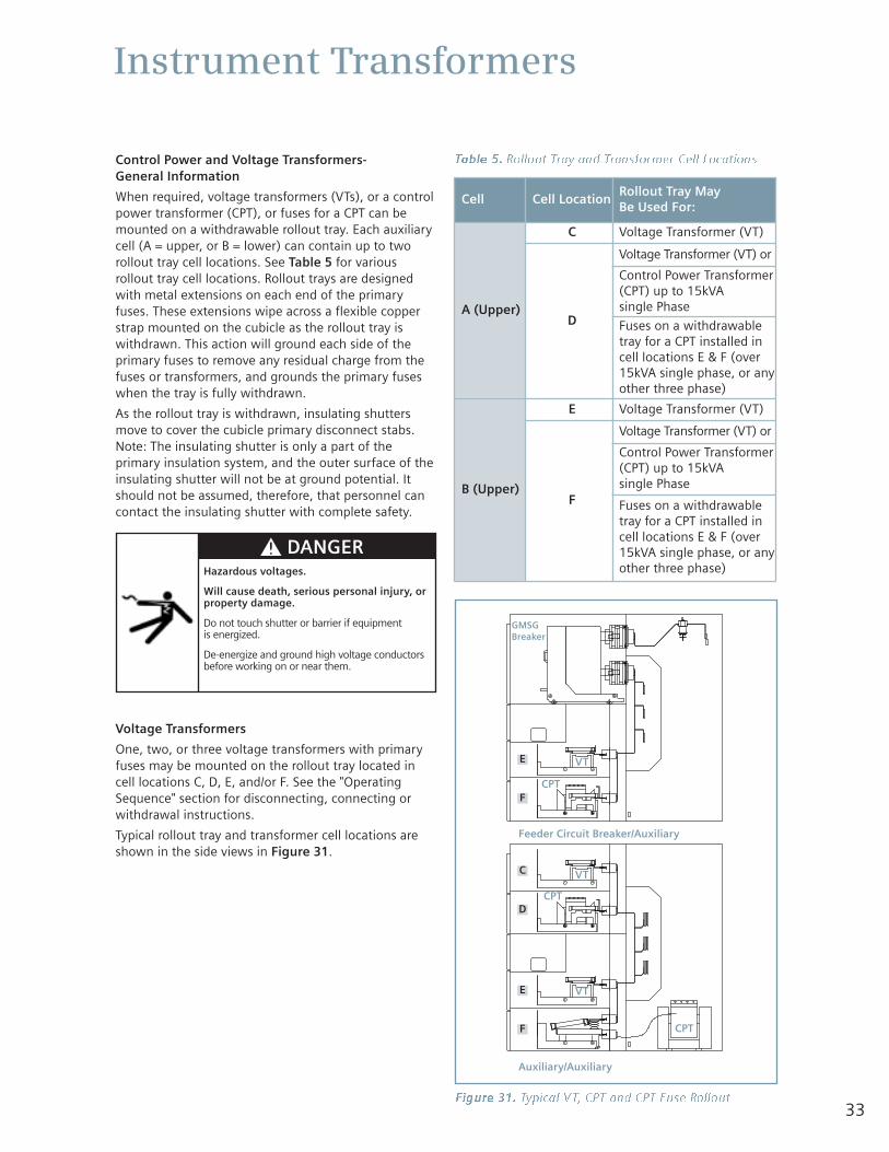
33
Instrument Transformers
Control Power and Voltage Transformers-General Information
When required, voltage transformers (VTs), or a controlpower transformer (CPT), or fuses for a CPT can bemounted on a withdrawable rollout tray. Each auxiliarycell (A = upper, or B = lower) can contain up to tworollout tray cell locations. See Table 5 for variousrollout tray cell locations. Rollout trays are designedwith metal extensions on each end of the primaryfuses. These extensions wipe across a flexible copperstrap mounted on the cubicle as the rollout tray iswithdrawn. This action will ground each side of theprimary fuses to remove any residual charge from thefuses or transformers, and grounds the primary fuseswhen the tray is fully withdrawn.
As the rollout tray is withdrawn, insulating shuttersmove to cover the cubicle primary disconnect stabs.Note: The insulating shutter is only a part of theprimary insulation system, and the outer surface of theinsulating shutter will not be at ground potential. Itshould not be assumed, therefore, that personnel cancontact the insulating shutter with complete safety.
Voltage Transformers
One, two, or three voltage transformers with primaryfuses may be mounted on the rollout tray located incell locations C, D, E, and/or F. See the "OperatingSequence" section for disconnecting, connecting orwithdrawal instructions.
Typical rollout tray and transformer cell locations areshown in the side views in Figure 31.
Figure 31. Typical VT, CPT and CPT Fuse Rollout
Hazardous voltages.
Will cause death, serious personal injury, orproperty damage.
Do not touch shutter or barrier if equipment is energized.
De-energize and ground high voltage conductorsbefore working on or near them.
Cell Cell LocationRollout Tray May Be Used For:
A (Upper)
C Voltage Transformer (VT)
D
Voltage Transformer (VT) or
Control Power Transformer(CPT) up to 15kVA single Phase
Fuses on a withdrawabletray for a CPT installed incell locations E & F (over15kVA single phase, or anyother three phase)
B (Upper)
E Voltage Transformer (VT)
F
Voltage Transformer (VT) or
Control Power Transformer(CPT) up to 15kVA single Phase
Fuses on a withdrawabletray for a CPT installed incell locations E & F (over15kVA single phase, or anyother three phase)
Table 5. Rollout Tray and Transformer Cell Locations
Feeder Circuit Breaker/Auxiliary
Auxiliary/Auxiliary
E
F
C
D
E
F
VT
GMSGBreaker
CPT
VT
VT
CPT
CPT
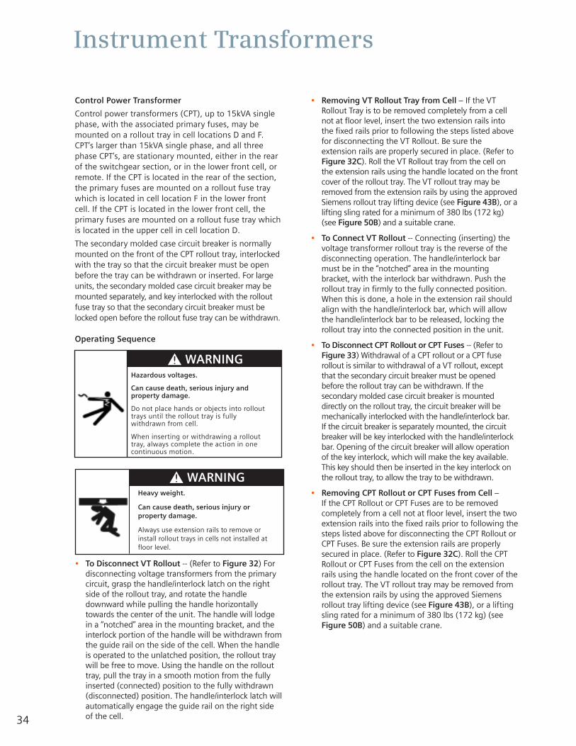
34
Instrument Transformers
Control Power Transformer
Control power transformers (CPT), up to 15kVA singlephase, with the associated primary fuses, may bemounted on a rollout tray in cell locations D and F.CPT’s larger than 15kVA single phase, and all threephase CPT’s, are stationary mounted, either in the rearof the switchgear section, or in the lower front cell, orremote. If the CPT is located in the rear of the section,the primary fuses are mounted on a rollout fuse traywhich is located in cell location F in the lower frontcell. If the CPT is located in the lower front cell, theprimary fuses are mounted on a rollout fuse tray whichis located in the upper cell in cell location D.
The secondary molded case circuit breaker is normallymounted on the front of the CPT rollout tray, interlockedwith the tray so that the circuit breaker must be openbefore the tray can be withdrawn or inserted. For largeunits, the secondary molded case circuit breaker may bemounted separately, and key interlocked with the rolloutfuse tray so that the secondary circuit breaker must belocked open before the rollout fuse tray can be withdrawn.
Operating Sequence
• To Disconnect VT Rollout -- (Refer to Figure 32) Fordisconnecting voltage transformers from the primarycircuit, grasp the handle/interlock latch on the rightside of the rollout tray, and rotate the handledownward while pulling the handle horizontallytowards the center of the unit. The handle will lodgein a “notched” area in the mounting bracket, and theinterlock portion of the handle will be withdrawn fromthe guide rail on the side of the cell. When the handleis operated to the unlatched position, the rollout traywill be free to move. Using the handle on the rollouttray, pull the tray in a smooth motion from the fullyinserted (connected) position to the fully withdrawn(disconnected) position. The handle/interlock latch willautomatically engage the guide rail on the right sideof the cell.
• Removing VT Rollout Tray from Cell – If the VTRollout Tray is to be removed completely from a cellnot at floor level, insert the two extension rails intothe fixed rails prior to following the steps listed abovefor disconnecting the VT Rollout. Be sure theextension rails are properly secured in place. (Refer toFigure 32C). Roll the VT Rollout tray from the cell onthe extension rails using the handle located on the frontcover of the rollout tray. The VT rollout tray may beremoved from the extension rails by using the approvedSiemens rollout tray lifting device (see Figure 43B), or alifting sling rated for a minimum of 380 lbs (172 kg)(see Figure 50B) and a suitable crane.
• To Connect VT Rollout -- Connecting (inserting) thevoltage transformer rollout tray is the reverse of thedisconnecting operation. The handle/interlock barmust be in the “notched” area in the mountingbracket, with the interlock bar withdrawn. Push therollout tray in firmly to the fully connected position.When this is done, a hole in the extension rail shouldalign with the handle/interlock bar, which will allowthe handle/interlock bar to be released, locking therollout tray into the connected position in the unit.
• To Disconnect CPT Rollout or CPT Fuses -- (Refer toFigure 33) Withdrawal of a CPT rollout or a CPT fuserollout is similar to withdrawal of a VT rollout, exceptthat the secondary circuit breaker must be openedbefore the rollout tray can be withdrawn. If thesecondary molded case circuit breaker is mounteddirectly on the rollout tray, the circuit breaker will bemechanically interlocked with the handle/interlock bar. If the circuit breaker is separately mounted, the circuitbreaker will be key interlocked with the handle/interlockbar. Opening of the circuit breaker will allow operationof the key interlock, which will make the key available.This key should then be inserted in the key interlock onthe rollout tray, to allow the tray to be withdrawn.
• Removing CPT Rollout or CPT Fuses from Cell – If the CPT Rollout or CPT Fuses are to be removedcompletely from a cell not at floor level, insert the twoextension rails into the fixed rails prior to following thesteps listed above for disconnecting the CPT Rollout orCPT Fuses. Be sure the extension rails are properlysecured in place. (Refer to Figure 32C). Roll the CPTRollout or CPT Fuses from the cell on the extensionrails using the handle located on the front cover of therollout tray. The VT rollout tray may be removed fromthe extension rails by using the approved Siemensrollout tray lifting device (see Figure 43B), or a liftingsling rated for a minimum of 380 lbs (172 kg) (seeFigure 50B) and a suitable crane.
Hazardous voltages.
Can cause death, serious injury andproperty damage.
Do not place hands or objects into rollouttrays until the rollout tray is fullywithdrawn from cell.
When inserting or withdrawing a rollouttray, always complete the action in onecontinuous motion.
Heavy weight.
Can cause death, serious injury orproperty damage.
Always use extension rails to remove orinstall rollout trays in cells not installed atfloor level.
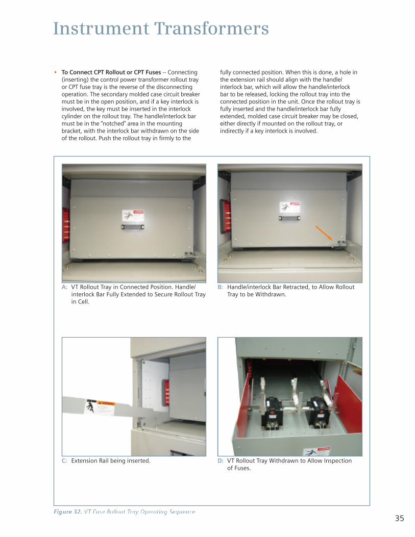
35
Instrument Transformers
• To Connect CPT Rollout or CPT Fuses -- Connecting(inserting) the control power transformer rollout trayor CPT fuse tray is the reverse of the disconnectingoperation. The secondary molded case circuit breakermust be in the open position, and if a key interlock isinvolved, the key must be inserted in the interlockcylinder on the rollout tray. The handle/interlock barmust be in the “notched” area in the mountingbracket, with the interlock bar withdrawn on the sideof the rollout. Push the rollout tray in firmly to the
fully connected position. When this is done, a hole inthe extension rail should align with the handle/interlock bar, which will allow the handle/interlock bar to be released, locking the rollout tray into theconnected position in the unit. Once the rollout tray isfully inserted and the handle/interlock bar fullyextended, molded case circuit breaker may be closed,either directly if mounted on the rollout tray, orindirectly if a key interlock is involved.
Figure 32. VT Fuse Rollout Tray Operating Sequence
A: VT Rollout Tray in Connected Position. Handle/interlock Bar Fully Extended to Secure Rollout Trayin Cell.
C: Extension Rail being inserted.
B: Handle/interlock Bar Retracted, to Allow RolloutTray to be Withdrawn.
D: VT Rollout Tray Withdrawn to Allow Inspection of Fuses.
36
Instrument Transformers
Figure 33. CPT Fuse Rollout Tray with Key Interlocking
A: Step1: Secondary circuit breaker is closed. Opensecondary circuit breaker.
C: Step 3: Key interlock on rollout tray is extended,preventing operation of handle/interlock bars. Insertkey, rotate key interlock, withdrawing interlock sothat handle/interlock bar is free to move.
B: Step 2: Secondary circuit breaker is open. Rotatekey interlock, extending interlock to block closingof secondary circuit breaker. Remove key.
D: Step 4: Key interlock withdrawn. Operate handle/interlock bar to allow withdrawal of rollout tray.
UnderConstruction
UnderConstruction
UnderConstruction
UnderConstruction
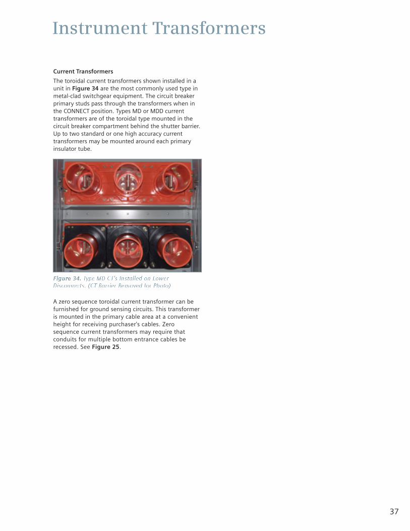
37
Instrument Transformers
Current Transformers
The toroidal current transformers shown installed in aunit in Figure 34 are the most commonly used type inmetal-clad switchgear equipment. The circuit breakerprimary studs pass through the transformers when inthe CONNECT position. Types MD or MDD currenttransformers are of the toroidal type mounted in thecircuit breaker compartment behind the shutter barrier.Up to two standard or one high accuracy currenttransformers may be mounted around each primaryinsulator tube.
A zero sequence toroidal current transformer can befurnished for ground sensing circuits. This transformeris mounted in the primary cable area at a convenientheight for receiving purchaser's cables. Zerosequence current transformers may require thatconduits for multiple bottom entrance cables berecessed. See Figure 25.
Figure 34. Type MD CT's Installed on LowerDisconnects. (CT Barrier Removed for Photo)
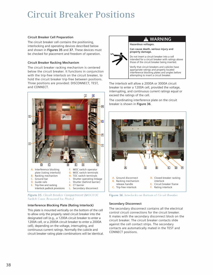
38
Circuit Breaker Positions
Circuit Breaker Cell Preparation
The circuit breaker cell contains the positioning,interlocking and operating devices described belowand shown in Figures 35 and 37. These devices mustbe checked for placement and freedom of operation.
Circuit Breaker Racking Mechanism
The circuit breaker racking mechanism is centeredbelow the circuit breaker. It functions in conjunctionwith the trip-free interlock on the circuit breaker, tohold the circuit breaker trip-free between positions.Three positions are provided: DISCONNECT, TEST,and CONNECT.
Interference Blocking Plate (Rating Interlock)
This plate is mounted vertically on the bottom of the cellto allow only the properly rated circuit breaker into thedesignated cell (e.g., a 1200A circuit breaker to enter a1200A cell, or a 2000A circuit breaker to enter a 2000Acell), depending on the voltage, interrupting, andcontinuous current ratings. Normally the cubicle andcircuit breaker rating plate combinations will be identical.
The interlock will allow a 2000A or 3000A circuitbreaker to enter a 1200A cell, provided the voltage,interrupting, and continuous current ratings equal orexceed the ratings of the cell.
The coordinating interference plate on the circuitbreaker is shown in Figure 36.
Secondary Disconnect
The secondary disconnect contains all the electricalcontrol circuit connections for the circuit breaker. It mates with the secondary disconnect block on thecircuit breaker. The circuit breaker contacts slideagainst the cell contact strips. The secondarycontacts are automatically mated in the TEST andCONNECT positions.
Figure 35. Circuit Breaker Compartment (MOC/TOCSwitch Cover Removed for Photo)
A. Interference blockingplate (rating interlock)
B. Racking mechanismC. Ground barD. Guide railsE. Trip-free and racking
interlock padlock provisions
F. MOC switch operatorG. MOC switch terminalsH. TOC switch terminalsI. Shutter operating linkageJ. Shutter (behind barrier)K. CT barrierL. Secondary disconnect
Figure 36. Interlocks on Bottom of Circuit Breaker
A. Ground disconnectB. Racking mechanism
release handleC. Trip-free interlock
D. Closed-breaker rackinginterlock
E. Circuit breaker frameF. Rating interlock
Hazardous voltages.
Can cause death, serious injury andproperty damage.
Do not insert a circuit breaker into a cellintended for a circuit breaker with ratings abovethose of the circuit breaker being inserted.
Verify that circuit breakers and cubicles haveappropriate ratings and properly locatedinterference blocking plates and angles beforeattempting to insert a circuit breaker.
A DEBCD
I
L
J K
H
G
F
I
A E B C D F
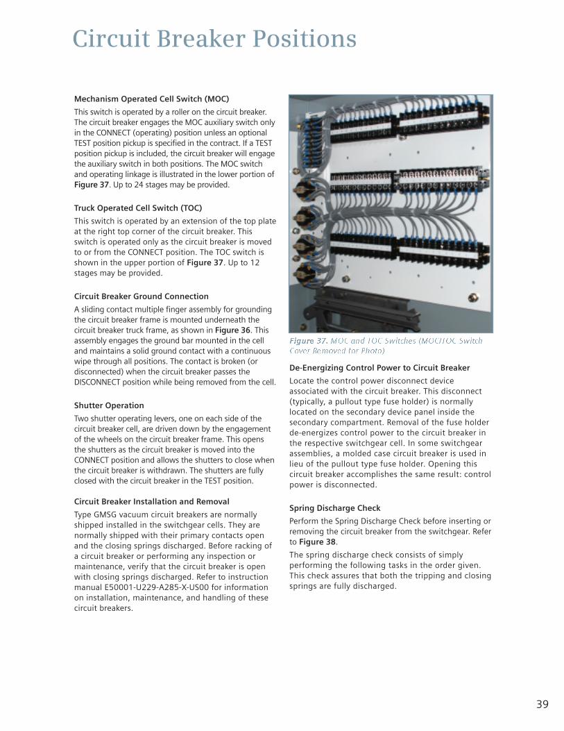
39
Circuit Breaker Positions
Mechanism Operated Cell Switch (MOC)
This switch is operated by a roller on the circuit breaker.The circuit breaker engages the MOC auxiliary switch onlyin the CONNECT (operating) position unless an optionalTEST position pickup is specified in the contract. If a TESTposition pickup is included, the circuit breaker will engagethe auxiliary switch in both positions. The MOC switchand operating linkage is illustrated in the lower portion ofFigure 37. Up to 24 stages may be provided.
Truck Operated Cell Switch (TOC)
This switch is operated by an extension of the top plateat the right top corner of the circuit breaker. Thisswitch is operated only as the circuit breaker is movedto or from the CONNECT position. The TOC switch isshown in the upper portion of Figure 37. Up to 12stages may be provided.
Circuit Breaker Ground Connection
A sliding contact multiple finger assembly for groundingthe circuit breaker frame is mounted underneath thecircuit breaker truck frame, as shown in Figure 36. Thisassembly engages the ground bar mounted in the celland maintains a solid ground contact with a continuouswipe through all positions. The contact is broken (ordisconnected) when the circuit breaker passes theDISCONNECT position while being removed from the cell.
Shutter Operation
Two shutter operating levers, one on each side of thecircuit breaker cell, are driven down by the engagementof the wheels on the circuit breaker frame. This opensthe shutters as the circuit breaker is moved into theCONNECT position and allows the shutters to close whenthe circuit breaker is withdrawn. The shutters are fullyclosed with the circuit breaker in the TEST position.
Circuit Breaker Installation and Removal
Type GMSG vacuum circuit breakers are normallyshipped installed in the switchgear cells. They arenormally shipped with their primary contacts openand the closing springs discharged. Before racking ofa circuit breaker or performing any inspection ormaintenance, verify that the circuit breaker is openwith closing springs discharged. Refer to instructionmanual E50001-U229-A285-X-US00 for informationon installation, maintenance, and handling of thesecircuit breakers.
De-Energizing Control Power to Circuit Breaker
Locate the control power disconnect deviceassociated with the circuit breaker. This disconnect(typically, a pullout type fuse holder) is normallylocated on the secondary device panel inside thesecondary compartment. Removal of the fuse holderde-energizes control power to the circuit breaker inthe respective switchgear cell. In some switchgearassemblies, a molded case circuit breaker is used inlieu of the pullout type fuse holder. Opening thiscircuit breaker accomplishes the same result: controlpower is disconnected.
Spring Discharge Check
Perform the Spring Discharge Check before inserting orremoving the circuit breaker from the switchgear. Referto Figure 38.
The spring discharge check consists of simplyperforming the following tasks in the order given.This check assures that both the tripping and closingsprings are fully discharged.
Figure 37. MOC and TOC Switches (MOC/TOC SwitchCover Removed for Photo)
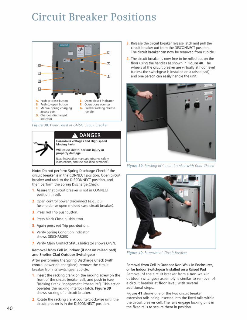
40
Circuit Breaker Positions
Figure 38. Front Panel of GMSG Circuit Breaker
A. Push-to-close buttonB. Push-to-open buttonC. Manual spring charging
access portD. Charged-discharged
indicator
E. Open-closed indicatorF. Operations counterG. Breaker racking release
handle
Hazardous voltages and High-speed Moving Parts
Will cause death, serious injury or property damage.
Read instruction manuals, observe safetyinstructions, and use qualified personnel.
Note: Do not perform Spring Discharge Check if thecircuit breaker is in the CONNECT position. Open circuitbreaker and rack to the DISCONNECT position, andthen perform the Spring Discharge Check.
1. Assure that circuit breaker is not in CONNECTposition in cell.
2. Open control power disconnect (e.g., pullfuseholder or open molded case circuit breaker).
3. Press red Trip pushbutton.
4. Press black Close pushbutton.
5. Again press red Trip pushbutton.
6. Verify Spring Condition Indicator shows DISCHARGED.
7. Verify Main Contact Status Indicator shows OPEN.
Removal from Cell in Indoor (if not on raised pad)and Shelter-Clad Outdoor Switchgear
After performing the Spring Discharge Check (withcontrol power de-energized), remove the circuitbreaker from its switchgear cubicle.
1. Insert the racking crank on the racking screw on thefront of the circuit breaker cell, and push in (see"Racking Crank Engagement Procedure"). This actionoperates the racking interlock latch. Figure 39shows racking of a circuit breaker.
2. Rotate the racking crank counterclockwise until thecircuit breaker is in the DISCONNECT position.
3. Release the circuit breaker release latch and pull thecircuit breaker out from the DISCONNECT position.The circuit breaker can now be removed from cubicle.
4. The circuit breaker is now free to be rolled out on thefloor using the handles as shown in Figure 40. Thewheels of the circuit breaker are virtually at floor level(unless the switchgear is installed on a raised pad),and one person can easily handle the unit.
Removal from Cell in Outdoor Non-Walk-In Enclosures,or for Indoor Switchgear Installed on a Raised PadRemoval of the circuit breaker from a non-walk-inoutdoor switchgear assembly is similar to removal ofa circuit breaker at floor level, with severaladditional steps.
Figure 41 shows one of the two circuit breakerextension rails being inserted into the fixed rails withinthe circuit breaker cell. The rails engage locking pins inthe fixed rails to secure them in position.
Figure 39. Racking of Circuit Breaker with Door Closed
Figure 40. Removal of Circuit Breaker
A
C
D
E
F
G
B
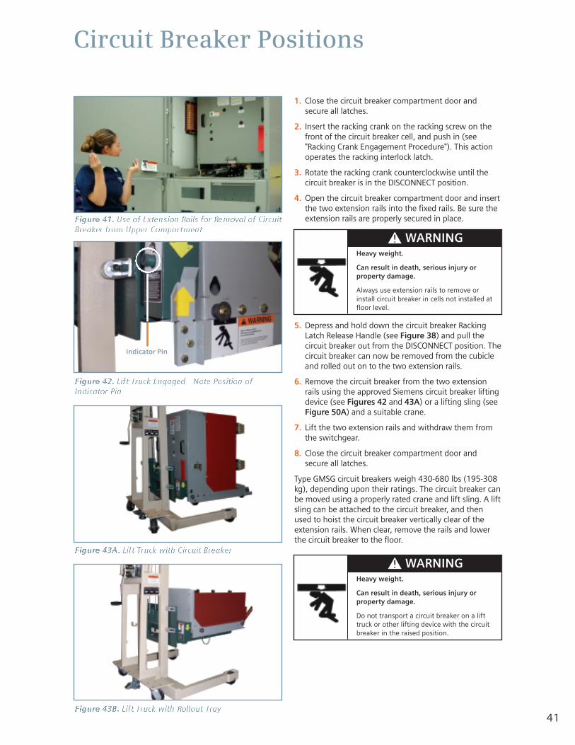
Circuit Breaker Positions
1. Close the circuit breaker compartment door andsecure all latches.
2. Insert the racking crank on the racking screw on thefront of the circuit breaker cell, and push in (see"Racking Crank Engagement Procedure"). This actionoperates the racking interlock latch.
3. Rotate the racking crank counterclockwise until thecircuit breaker is in the DISCONNECT position.
4. Open the circuit breaker compartment door and insertthe two extension rails into the fixed rails. Be sure theextension rails are properly secured in place.
5. Depress and hold down the circuit breaker RackingLatch Release Handle (see Figure 38) and pull thecircuit breaker out from the DISCONNECT position. Thecircuit breaker can now be removed from the cubicleand rolled out on to the two extension rails.
6. Remove the circuit breaker from the two extensionrails using the approved Siemens circuit breaker liftingdevice (see Figures 42 and 43A) or a lifting sling (seeFigure 50A) and a suitable crane.
7. Lift the two extension rails and withdraw them fromthe switchgear.
8. Close the circuit breaker compartment door andsecure all latches.
Type GMSG circuit breakers weigh 430-680 lbs (195-308kg), depending upon their ratings. The circuit breaker canbe moved using a properly rated crane and lift sling. A liftsling can be attached to the circuit breaker, and thenused to hoist the circuit breaker vertically clear of theextension rails. When clear, remove the rails and lowerthe circuit breaker to the floor.
Figure 41. Use of Extension Rails for Removal of CircuitBreaker from Upper Compartment
Figure 42. Lift Truck Engaged - Note Position ofIndicator Pin
Indicator Pin
Figure 43A. Lift Truck with Circuit Breaker
Figure 43B. Lift Truck with Rollout Tray
Heavy weight.
Can result in death, serious injury orproperty damage.
Always use extension rails to remove orinstall circuit breaker in cells not installed atfloor level.
Heavy weight.
Can result in death, serious injury orproperty damage.
Do not transport a circuit breaker on a lifttruck or other lifting device with the circuitbreaker in the raised position.
41
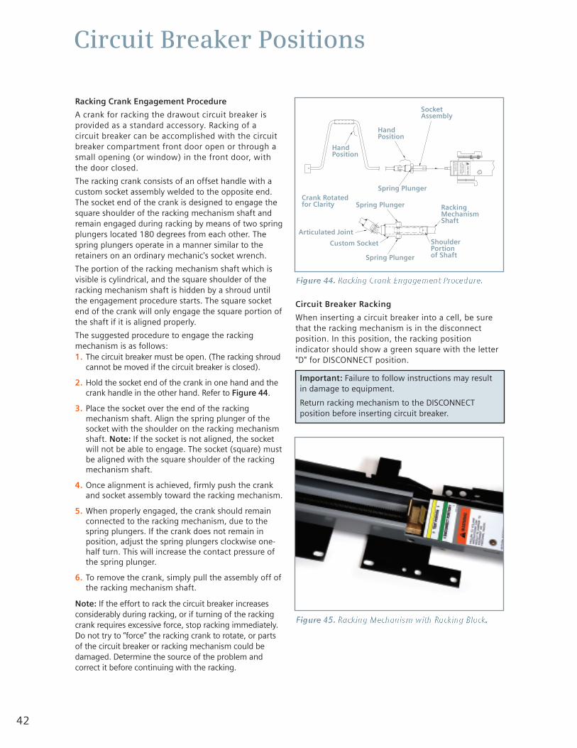
42
Circuit Breaker Positions
Racking Crank Engagement Procedure
A crank for racking the drawout circuit breaker isprovided as a standard accessory. Racking of acircuit breaker can be accomplished with the circuitbreaker compartment front door open or through asmall opening (or window) in the front door, withthe door closed.
The racking crank consists of an offset handle with acustom socket assembly welded to the opposite end.The socket end of the crank is designed to engage thesquare shoulder of the racking mechanism shaft andremain engaged during racking by means of two springplungers located 180 degrees from each other. Thespring plungers operate in a manner similar to theretainers on an ordinary mechanic's socket wrench.
The portion of the racking mechanism shaft which isvisible is cylindrical, and the square shoulder of theracking mechanism shaft is hidden by a shroud untilthe engagement procedure starts. The square socketend of the crank will only engage the square portion ofthe shaft if it is aligned properly.
The suggested procedure to engage the rackingmechanism is as follows:1. The circuit breaker must be open. (The racking shroud
cannot be moved if the circuit breaker is closed).
2. Hold the socket end of the crank in one hand and thecrank handle in the other hand. Refer to Figure 44.
3. Place the socket over the end of the rackingmechanism shaft. Align the spring plunger of thesocket with the shoulder on the racking mechanismshaft. Note: If the socket is not aligned, the socketwill not be able to engage. The socket (square) mustbe aligned with the square shoulder of the rackingmechanism shaft.
4. Once alignment is achieved, firmly push the crankand socket assembly toward the racking mechanism.
5. When properly engaged, the crank should remainconnected to the racking mechanism, due to thespring plungers. If the crank does not remain inposition, adjust the spring plungers clockwise one-half turn. This will increase the contact pressure ofthe spring plunger.
6. To remove the crank, simply pull the assembly off ofthe racking mechanism shaft.
Note: If the effort to rack the circuit breaker increasesconsiderably during racking, or if turning of the rackingcrank requires excessive force, stop racking immediately.Do not try to “force” the racking crank to rotate, or partsof the circuit breaker or racking mechanism could bedamaged. Determine the source of the problem andcorrect it before continuing with the racking.
Circuit Breaker Racking
When inserting a circuit breaker into a cell, be surethat the racking mechanism is in the disconnectposition. In this position, the racking positionindicator should show a green square with the letter"D" for DISCONNECT position.
MSIN
AHC E
M GN
IKCA
R NR
UTER
NOI
T IS
OP "
D " EH
T OT
.REK
AER B
GN
ITR E
SNI
E RO F
EB
W OLL
O F
OT E
RUL I
AFT L
USER
DL U
OC S
NOI
TCUR
TSNI
.TNE
MPI U
QE
OT E
GAMA
D NI
NOI
TU
AC
Figure 44. Racking Crank Engagement Procedure.
Figure 45. Racking Mechanism with Racking Block.
Important: Failure to follow instructions may resultin damage to equipment.
Return racking mechanism to the DISCONNECTposition before inserting circuit breaker.
HandPosition
HandPosition
SocketAssembly
Spring Plunger
Spring PlungerCrank Rotatedfor Clarity
Articulated Joint
Custom Socket
Spring Plunger
RackingMechanismShaft
ShoulderPortion of Shaft
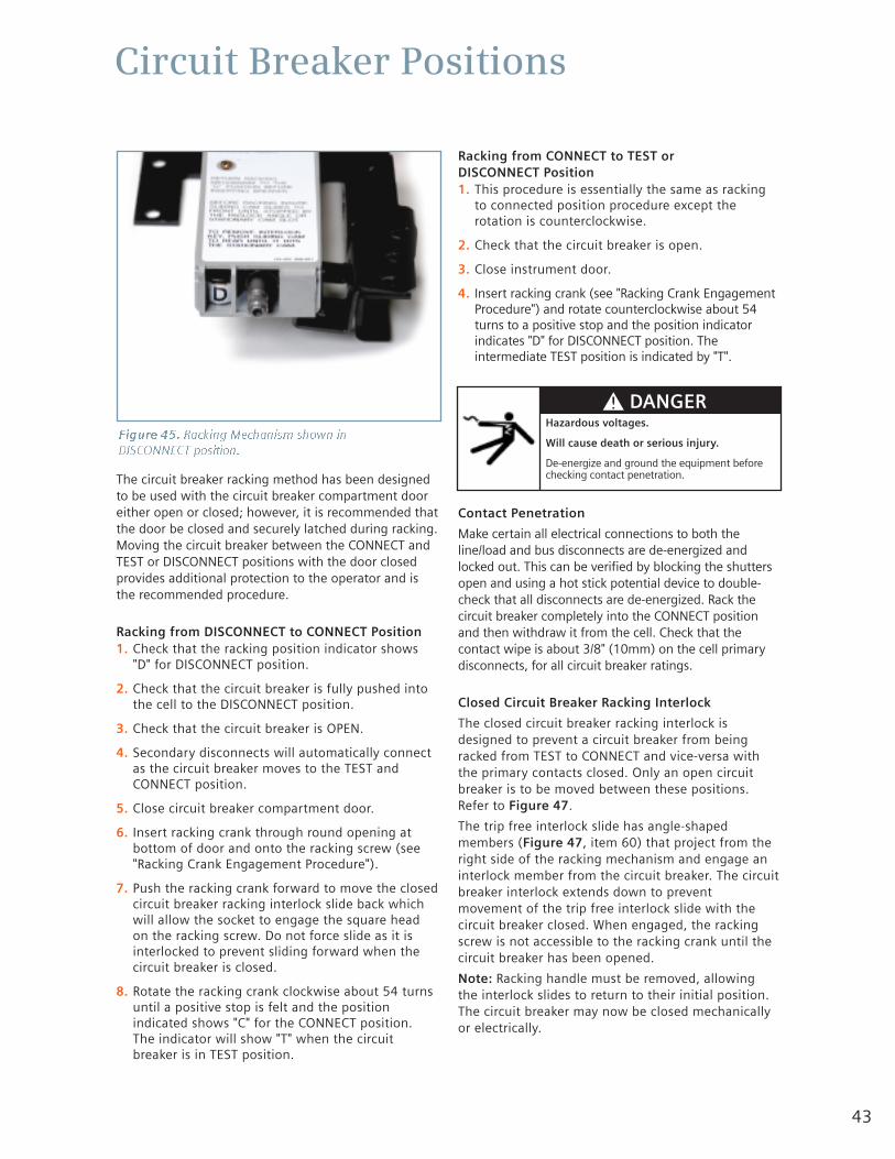
43
Circuit Breaker Positions
The circuit breaker racking method has been designedto be used with the circuit breaker compartment dooreither open or closed; however, it is recommended thatthe door be closed and securely latched during racking.Moving the circuit breaker between the CONNECT andTEST or DISCONNECT positions with the door closedprovides additional protection to the operator and isthe recommended procedure.
Racking from DISCONNECT to CONNECT Position1. Check that the racking position indicator shows
"D" for DISCONNECT position.
2. Check that the circuit breaker is fully pushed intothe cell to the DISCONNECT position.
3. Check that the circuit breaker is OPEN.
4. Secondary disconnects will automatically connectas the circuit breaker moves to the TEST andCONNECT position.
5. Close circuit breaker compartment door.
6. Insert racking crank through round opening atbottom of door and onto the racking screw (see"Racking Crank Engagement Procedure").
7. Push the racking crank forward to move the closedcircuit breaker racking interlock slide back whichwill allow the socket to engage the square headon the racking screw. Do not force slide as it isinterlocked to prevent sliding forward when thecircuit breaker is closed.
8. Rotate the racking crank clockwise about 54 turnsuntil a positive stop is felt and the positionindicated shows "C" for the CONNECT position. The indicator will show "T" when the circuitbreaker is in TEST position.
Racking from CONNECT to TEST or DISCONNECT Position1. This procedure is essentially the same as racking
to connected position procedure except therotation is counterclockwise.
2. Check that the circuit breaker is open.
3. Close instrument door.
4. Insert racking crank (see "Racking Crank EngagementProcedure") and rotate counterclockwise about 54turns to a positive stop and the position indicatorindicates "D" for DISCONNECT position. Theintermediate TEST position is indicated by "T".
Contact Penetration
Make certain all electrical connections to both theline/load and bus disconnects are de-energized andlocked out. This can be verified by blocking the shuttersopen and using a hot stick potential device to double-check that all disconnects are de-energized. Rack thecircuit breaker completely into the CONNECT positionand then withdraw it from the cell. Check that thecontact wipe is about 3/8" (10mm) on the cell primarydisconnects, for all circuit breaker ratings.
Closed Circuit Breaker Racking Interlock
The closed circuit breaker racking interlock isdesigned to prevent a circuit breaker from beingracked from TEST to CONNECT and vice-versa withthe primary contacts closed. Only an open circuitbreaker is to be moved between these positions.Refer to Figure 47.
The trip free interlock slide has angle-shapedmembers (Figure 47, item 60) that project from theright side of the racking mechanism and engage aninterlock member from the circuit breaker. The circuitbreaker interlock extends down to preventmovement of the trip free interlock slide with thecircuit breaker closed. When engaged, the rackingscrew is not accessible to the racking crank until thecircuit breaker has been opened.
Note: Racking handle must be removed, allowing the interlock slides to return to their initial position.The circuit breaker may now be closed mechanicallyor electrically.
Figure 45. Racking Mechanism shown in DISCONNECT position.
Hazardous voltages.
Will cause death or serious injury.
De-energize and ground the equipment beforechecking contact penetration.
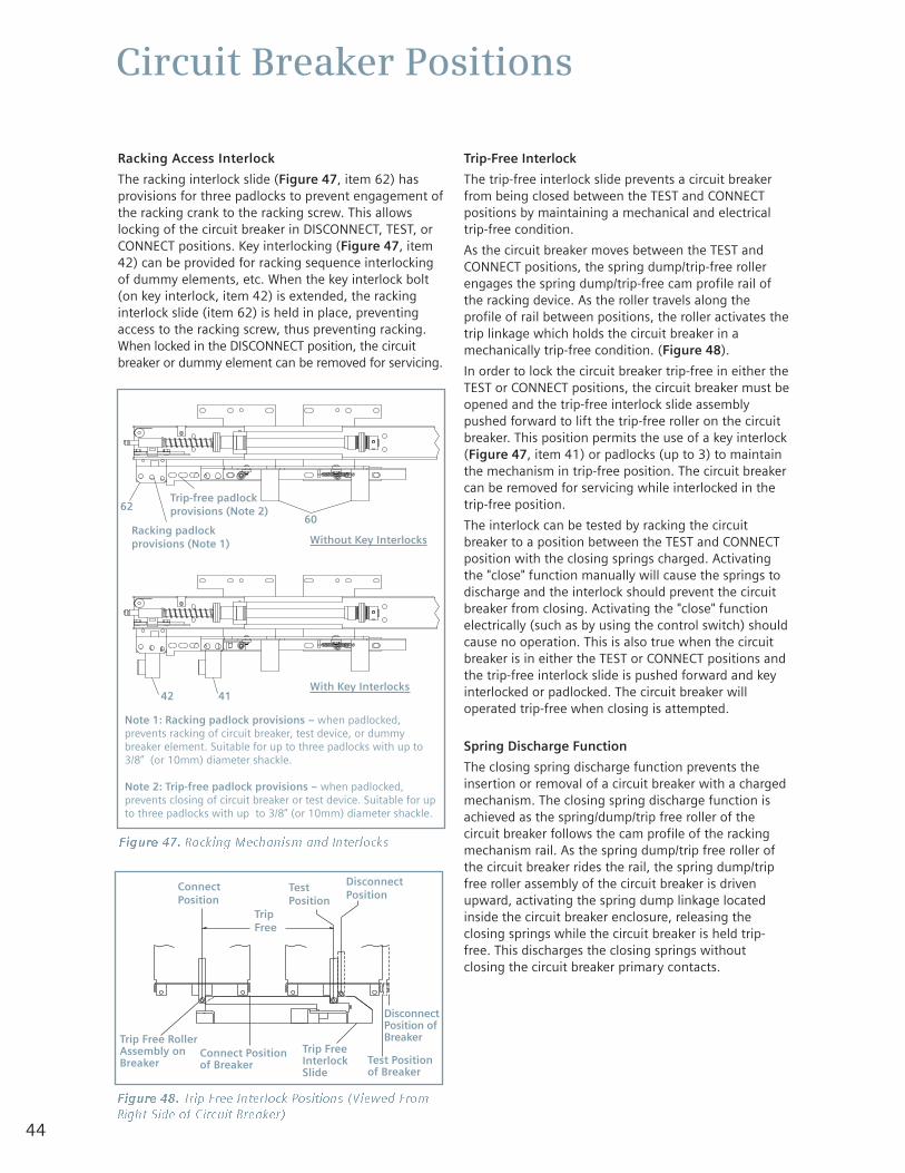
44
Circuit Breaker Positions
Racking Access Interlock
The racking interlock slide (Figure 47, item 62) hasprovisions for three padlocks to prevent engagement ofthe racking crank to the racking screw. This allowslocking of the circuit breaker in DISCONNECT, TEST, orCONNECT positions. Key interlocking (Figure 47, item42) can be provided for racking sequence interlockingof dummy elements, etc. When the key interlock bolt(on key interlock, item 42) is extended, the rackinginterlock slide (item 62) is held in place, preventingaccess to the racking screw, thus preventing racking.When locked in the DISCONNECT position, the circuitbreaker or dummy element can be removed for servicing.
Trip-Free Interlock
The trip-free interlock slide prevents a circuit breakerfrom being closed between the TEST and CONNECTpositions by maintaining a mechanical and electricaltrip-free condition.
As the circuit breaker moves between the TEST andCONNECT positions, the spring dump/trip-free rollerengages the spring dump/trip-free cam profile rail ofthe racking device. As the roller travels along theprofile of rail between positions, the roller activates thetrip linkage which holds the circuit breaker in amechanically trip-free condition. (Figure 48).
In order to lock the circuit breaker trip-free in either theTEST or CONNECT positions, the circuit breaker must beopened and the trip-free interlock slide assemblypushed forward to lift the trip-free roller on the circuitbreaker. This position permits the use of a key interlock(Figure 47, item 41) or padlocks (up to 3) to maintainthe mechanism in trip-free position. The circuit breakercan be removed for servicing while interlocked in thetrip-free position.
The interlock can be tested by racking the circuitbreaker to a position between the TEST and CONNECTposition with the closing springs charged. Activatingthe "close" function manually will cause the springs todischarge and the interlock should prevent the circuitbreaker from closing. Activating the "close" functionelectrically (such as by using the control switch) shouldcause no operation. This is also true when the circuitbreaker is in either the TEST or CONNECT positions andthe trip-free interlock slide is pushed forward and keyinterlocked or padlocked. The circuit breaker willoperated trip-free when closing is attempted.
Spring Discharge Function
The closing spring discharge function prevents theinsertion or removal of a circuit breaker with a chargedmechanism. The closing spring discharge function isachieved as the spring/dump/trip free roller of thecircuit breaker follows the cam profile of the rackingmechanism rail. As the spring dump/trip free roller ofthe circuit breaker rides the rail, the spring dump/tripfree roller assembly of the circuit breaker is drivenupward, activating the spring dump linkage locatedinside the circuit breaker enclosure, releasing theclosing springs while the circuit breaker is held trip-free. This discharges the closing springs withoutclosing the circuit breaker primary contacts.
Figure 47. Racking Mechanism and Interlocks
Figure 48. Trip Free Interlock Positions (Viewed FromRight Side of Circuit Breaker)
Note 1: Racking padlock provisions – when padlocked,prevents racking of circuit breaker, test device, or dummybreaker element. Suitable for up to three padlocks with up to3/8” (or 10mm) diameter shackle.
Note 2: Trip-free padlock provisions – when padlocked,prevents closing of circuit breaker or test device. Suitable for upto three padlocks with up to 3/8” (or 10mm) diameter shackle.
6260
42
ConnectPosition
TripFree
TestPosition
DisconnectPosition
Trip Free RollerAssembly onBreaker
Connect Positionof Breaker
Trip FreeInterlockSlide
Test Positionof Breaker
DisconnectPosition ofBreaker
41
Racking padlockprovisions (Note 1) Without Key Interlocks
With Key Interlocks
Trip-free padlockprovisions (Note 2)
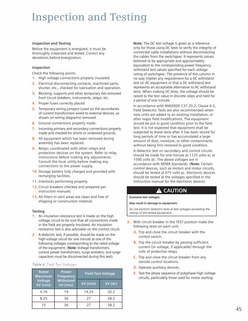
45
Inspection and Testing
Inspection and Testing
Before the equipment is energized, it must bethoroughly inspected and tested. Correct anydeviations before energization.
Inspection
Check the following points:1. High voltage connections properly insulated.
2. Electrical disconnecting contacts, machined parts,shutter, etc., checked for lubrication and operation.
3. Blocking, supports and other temporary ties removedfrom circuit breakers, instruments, relays, etc.
4. Proper fuses correctly placed.
5. Temporary wiring jumpers (used on the secondariesof current transformers wired to external devices, asshown on wiring diagrams) removed.
6. Ground connections properly made.
7. Incoming primary and secondary connections properlymade and checked for shorts or undesired grounds.
8. All equipment which has been removed duringassembly has been replaced.
9. Relays coordinated with other relays andprotection devices on the system. Refer to relayinstructions before making any adjustments.Consult the local utility before making anyconnections to the power supply.
10. Storage battery fully charged and provided withrecharging facilities.
11. Interlocks performing properly.
12. Circuit breakers checked and prepared perinstruction manuals.
13. All filters in vent areas are clean and free ofshipping or construction material.
Testing1. An insulation resistance test is made on the high
voltage circuit to be sure that all connections madein the field are properly insulated. An insulationresistance test is also advisable on the control circuit.
2. A dielectric test, if possible, should be made on thehigh voltage circuit for one minute at one of thefollowing voltages corresponding to the rated voltageof the equipment. (Note: Voltage transformers,control power transformers, surge arresters, and surgecapacitors must be disconnected during this test).
Note: The DC test voltage is given as a referenceonly for those using DC tests to verify the integrity ofconnected cable installations without disconnectingthe cables from the switchgear. It represents valuesbelieved to be appropriate and approximatelyequivalent to the corresponding power frequencywithstand test values specified for each voltagerating of switchgear. The presence of this column inno way implies any requirement for a DC withstandtest on AC equipment or that a DC withstand testrepresents an acceptable alternative to AC withstandtests. When making DC tests, the voltage should beraised to the test value in discrete steps and held fora period of one minute.
In accordance with ANSI/IEEE C37.20.2, Clause 6.5,Field Dielectric Tests are also recommended whennew units are added to an existing installation, orafter major field modifications. The equipmentshould be put in good condition prior to the fieldtest. It is not expected that equipment shall besubjected to these tests after it has been stored forlong periods of time or has accumulated a largeamount of dust, moisture, or other contaminantswithout being first restored to good condition.
A dielectric test on secondary and control circuitsshould be made for one minute at 1125 volts ac or1590 volts dc. The above voltages are inaccordance with NEMA Standards. (Note: Certaincontrol devices, such as motors and motor circuits,should be tested at 675 volts ac. Electronic devicesshould be tested at the voltages specified in theinstruction manual for the electronic device).
3. With circuit breaker in the TEST position make thefollowing tests on each unit:
A. Trip and close the circuit breaker with thecontrol switch.
B. Trip the circuit breaker by passing sufficientcurrent (or voltage, if applicable) through thecoils of protective relays.
C. Trip and close the circuit breaker from anyremote control locations.
D. Operate auxiliary devices.
E. Test the phase sequence of polyphase high voltagecircuits, particularly those used for motor starting.
Table 6. Field Test Voltages
RatedMaximum
VoltagekV (rms)
PowerFrequencyWithstandkV (rms)
Field Test Voltage
kV (rms) kV (dc)
4.76 19 14.25 20.2
8.25 36 27 38.2
15 36 27 38.2
Excessive test voltages.
May result in damage to equipment.
Do not perform dielectric tests at test voltages exceeding theratings of the tested equipment.

46
Inspection and Testing
Placing Equipment into Service
To place equipment in service for the first time proceedas follows:1. Check that all circuit breakers are open and all
control circuits energized.
2. Connect primary incoming power source to equipment.
3. Check all instruments, relays, meters, etc., duringthis time.
4. Connect as small a load as possible and observeinstruments. Note: Allow several minutes beforeconnecting additional load.
5. Gradually connect more load to the equipmentwhile observing instruments until the full load is connected.
6. Check for signs of overheating of primary andsecondary circuits and satisfactory operation of allinstruments during the first week of operation.
47
Maintenance
Introduction and Maintenance Intervals
Periodic inspections and maintenance are essential toobtain safe and reliable operation of the switchgear.When Type GM-SG switchgear is operated under "UsualService Conditions", maintenance and lubrication isrecommended at five year intervals. "Usual" and"Unusual" service conditions for Medium VoltageMetal-Clad Switchgear are defined in ANSI/IEEEC37.20.2, clauses 4 and 8.1. Generally, "usual serviceconditions" are defined as an environment in which theequipment is not exposed to excessive dust, acidfumes, damaging chemicals, salt air, rapid or frequentchanges in temperature, vibration, high humidity, andextremes of temperature.
The definition of "usual service conditions" is subject toa variety of interpretations. Because of this, you arebest served by adjusting maintenance and lubricationintervals based on your experience with the equipmentin the actual service environment.
Regardless of the length of the maintenance andlubrication interval, Siemens recommends that circuitbreakers should be inspected and exercised annually.
For the safety of maintenance personnel as well asothers who might be exposed to hazards associatedwith maintenance activities, the safety related workpractices of NFPA 70E should always be followed whenworking on electrical equipment. Maintenancepersonnel should be trained in the safety practices,procedures and requirements that pertain to theirrespective job assignments. This manual should bereviewed and retained in a location readily accessiblefor reference during maintenance of this equipment.
The user must establish a periodic maintenanceprogram to ensure trouble-free and safe operation. The frequency of inspection, periodic cleaning, andpreventive maintenance schedule will depend upon theoperation conditions. NFPA Publication 70B, "ElectricalEquipment Maintenance" may be used as a guide toestablish such a program. A preventive maintenanceprogram is not intended to cover reconditioning ormajor repair, but should be designed to reveal, ifpossible, the need for such actions in time toprevent malfunctions during operation.
Switchgear assemblies are enclosed on all sides andtop with sheet metal. Access into the enclosure isprovided by doors or removable covers. Although thebus and connections are insulated in metal-cladswitchgear assemblies, it is a coordinated insulationsystem; insulation plus air or creep distance equals agiven insulation level.
See ANSI/IEEE C37.20.2, clause 7.9, which reads as follows:
“This insulating covering is a requirement of metal-clad
switchgear and is provided to minimize the possibility of
communicating faults and to prevent development of bus
faults that would result if foreign objects momentarily
contacted bare bus. This insulating covering is usually only
a part of the primary insulation system, and in such cases
the outer surface of this insulating covering will not be at
ground potential. It should not be assumed, therefore, that
personnel can contact this insulating covering with com-
plete safety.”
Recommended Hand Tools
Type GM-SG switchgear and type GMSG circuit breakersuse both standard imperial (U.S. customary) and metricfasteners. Imperial (U.S. customary) fasteners are usedin most locations in the switchgear cubicles.
Recommended Maintenance and Lubrication
Periodic maintenance and lubrication should include allthe tasks shown in Table 7.
Hazardous voltages and High-speed Moving Parts
Will cause death, serious injury or property damage.
Do not work on energized equipment. Alwaysde-energize and ground the equipment beforeworking on the equipment.
Hazardous voltages and High-speed Moving Parts
Will cause death, serious injury or property damage.
Do not contact energized conductors. Beforeworking on or near high voltage conductorswithin switchgear, be sure they are de-energized and properly grounded.
Failure to maintain the equipment couldresult in death, serious injury or productfailure, and can prevent successfulfunctioning of connected apparatus.
The instructions contained herein should becarefully reviewed, understood, and followed.
The maintenance tasks in Table 7 must beperformed regularly.

48
Maintenance
The list of tasks in Table 7 does not represent anexhaustive survey of maintenance steps necessary toensure safe operation of the equipment. Particularapplications may require further procedures. Shouldfurther information be desired or should particularproblems arise which are not covered sufficiently forthe Purchaser's purposes, the matter should be referredto Siemens at 1-800-347-6659 (919-365-2200 outsidethe U.S.).
LubricationIt is essential that switchgear be lubricated carefullyand properly to guard against corrosion and to insurethat all operating parts work freely.
Old grease should be removed annually and partsrelubricated. Relubricate at more frequent intervals ifrequired with Siemens lubricant Part No. 18-671-001-501.
Moving PartsLubricate shutter guide, bearings, rollout fuse truckmoving parts, etc., with dry spray lubricant SiemensPart No. 15-172-816-058. Note: Use of lubricant notsuitable for the application will make the mechanismvery difficult to operate.Electrical Contacts
Lubricate stationary silver-surfaced contacts withelectrical contact lubricant Part No. 15-172-791-233prior to use, as follows:
1. Wipe contacts clean.
2. Apply lubricant to contact surfaces.
3. Wipe off excess lubricant, leaving a film. Avoidgetting lubricant on insulation.
Table 7. Maintenance Tasks
1. Before any maintenance work is performed withinprimary compartments, make certain that theequipment is completely de-energized, tested,grounded, tagged or locked out and released forwork in an authorized manner.
2. Before starting work on the switchgear, the follow-ing should be completed on any equipment thatwill affect the area of the work:
A. Disable remote control and automatic transfer schemes.
B. De-energize all direct and backfeed powerand control sources, test and ground.
C. Disconnect all voltage and control power transformers.
D. Open all disconnects.
3. Include the following items in your inspection procedure:
A. Check general condition of switchgear installation.
B. Inspect switchgear interior for accumulation ofdust, dirt or any foreign matter.
C. Clean air filters by washing in any mildhousehold detergent.
D. Examine indicating lamps and replace as required.
E. Check terminal block contacts for loose connections.
F. Check instrument and control switches andinspect their contacts.
G. Check for proper condition of instrumenttransformers. Replace burned out fuses, if any.Check primary and secondary connections.
H. Remove dust from all insulators and insulation.
I. Inspect bus bars and connections for propercondition. If bus bars are overheating check forpoor or loose connections or for overload.
J. Examine automatic shutters for proper operation.
K. Examine all safety interlocks.
L. Perform maintenance of circuit breakers asoutlined in circuit breaker instruction manual.
M.Check space heaters and thermostat (ifequipped) for proper operation.
N. Maintain other equipment in accordance withthe respective instruction book requirements.
O. Lubricate mechanisms, contacts, and othermoving components.
P. Replace, reassemble, re-insulate, return allitems to proper operating conditions andremove grounds prior to energization.
The use of unauthorized parts in the repair of theequipment, or tampering by unqualified personnel willresult in dangerous conditions which will cause death,serious injury or equipment damage.
Follow all safety instructions contained herein.
Hazardous voltages.
Will cause death, serious injury, andproperty damage.
Do not open shutters unless both line/load andbus are first de-energized.
49
Maintenance
Cleaning InsulationMost of the plastics and synthetics used in insulationsystems are attacked by solvents containing aromaticsor halogenated hydrocarbons. The use of these maycause crazing and deformation of the materialreducing the dielectric strength. Isopropyl alcohol isthe only recommended solvent cleaner.
Corrosive AtmospheresThis switchgear is designed to give top performancewhen installed in normal indoor or outdoorlocations. Where abnormal conditions, such ascorrosive atmospheres, are encountered, specialprecautions must be taken to minimize their effect.Exposed metallic surfaces, non-insulated bus bars,disconnect switches, primary and secondarydisconnecting contacts, wire ends, instrumentterminals, etc., must all be protected. At eachmaintenance inspection, all of the old grease shouldbe wiped off of the contacts and new lubricantapplied to all sliding surfaces. Apply the contactlubricant in a layer .03-.06" (1-2mm) thick. Use onlySiemens Electrical Contact Lubricant, Part No. 15-172-791-233, available in 8 oz. (.23kg) cans. Otherexposed components can be protected with a coat ofglyptol or other corrosion-resistant coating.
When old grease becomes dirty, wipe the part cleanand apply new grease immediately.
Relays and InstrumentsTo insure satisfactory operation of relays andinstruments do not leave device covers off longerthan necessary. When a cover has been broken, coverthe device temporarily and replace broken glass assoon as possible.
Equipment SurfacesInspect the painted surfaces and touch up scratches asnecessary. Touchup paint is available from Siemens.This paint matches the unit and is thinned and readyfor use in one pint (473ml) spray cans.
The use of unauthorized parts in the repair of theequipment, or tampering by unqualified personnel willresult in dangerous conditions which will cause death,serious injury or equipment damage.
Follow all safety instructions contained herein.
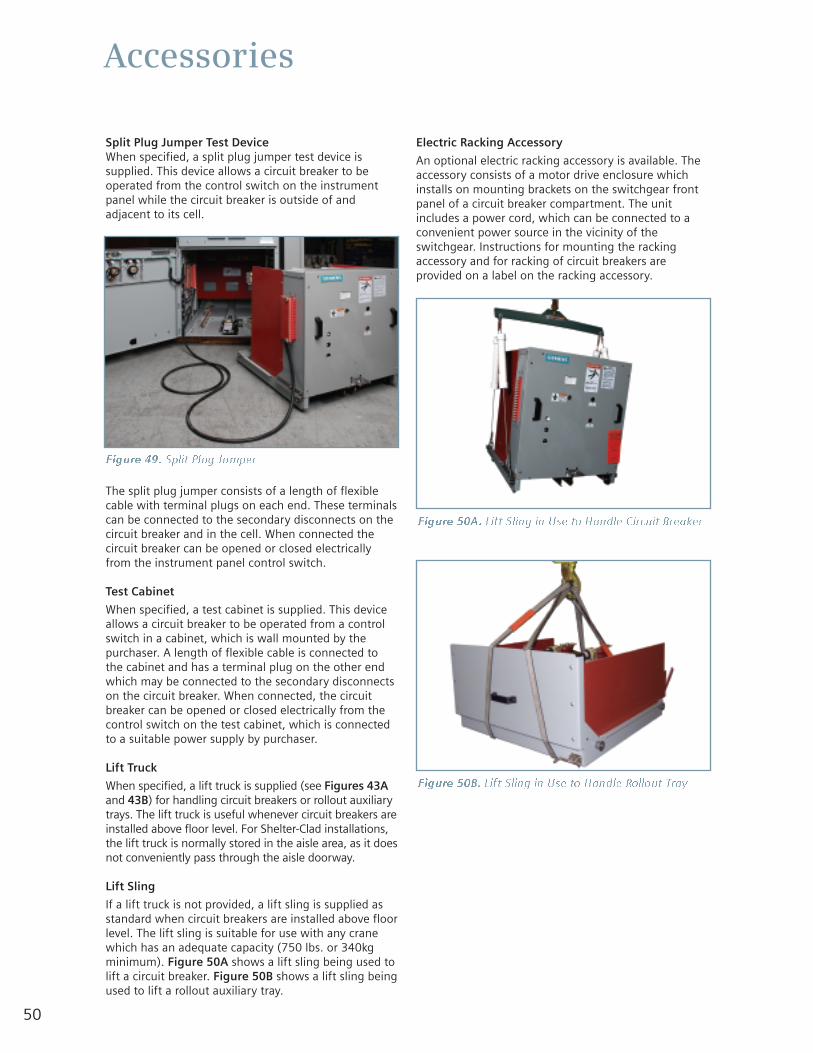
50
Accessories
Split Plug Jumper Test DeviceWhen specified, a split plug jumper test device issupplied. This device allows a circuit breaker to beoperated from the control switch on the instrumentpanel while the circuit breaker is outside of andadjacent to its cell.
The split plug jumper consists of a length of flexiblecable with terminal plugs on each end. These terminalscan be connected to the secondary disconnects on thecircuit breaker and in the cell. When connected thecircuit breaker can be opened or closed electricallyfrom the instrument panel control switch.
Test Cabinet
When specified, a test cabinet is supplied. This deviceallows a circuit breaker to be operated from a controlswitch in a cabinet, which is wall mounted by thepurchaser. A length of flexible cable is connected tothe cabinet and has a terminal plug on the other endwhich may be connected to the secondary disconnectson the circuit breaker. When connected, the circuitbreaker can be opened or closed electrically from thecontrol switch on the test cabinet, which is connectedto a suitable power supply by purchaser.
Lift Truck
When specified, a lift truck is supplied (see Figures 43Aand 43B) for handling circuit breakers or rollout auxiliarytrays. The lift truck is useful whenever circuit breakers areinstalled above floor level. For Shelter-Clad installations,the lift truck is normally stored in the aisle area, as it doesnot conveniently pass through the aisle doorway.
Lift Sling
If a lift truck is not provided, a lift sling is supplied asstandard when circuit breakers are installed above floorlevel. The lift sling is suitable for use with any cranewhich has an adequate capacity (750 lbs. or 340kgminimum). Figure 50A shows a lift sling being used tolift a circuit breaker. Figure 50B shows a lift sling beingused to lift a rollout auxiliary tray.
Electric Racking Accessory
An optional electric racking accessory is available. Theaccessory consists of a motor drive enclosure whichinstalls on mounting brackets on the switchgear frontpanel of a circuit breaker compartment. The unitincludes a power cord, which can be connected to aconvenient power source in the vicinity of theswitchgear. Instructions for mounting the rackingaccessory and for racking of circuit breakers areprovided on a label on the racking accessory.
Figure 49. Split Plug Jumper
Figure 50A. Lift Sling in Use to Handle Circuit Breaker
Figure 50B. Lift Sling in Use to Handle Rollout Tray
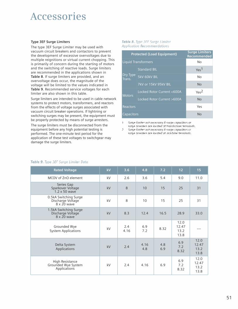
51
Accessories
Type 3EF Surge Limiters
The type 3EF Surge Limiter may be used withvacuum circuit breakers and contactors to preventthe development of excessive overvoltages due tomultiple reignitions or virtual current chopping. Thisis primarily of concern during the starting of motorsand the switching of reactive loads. Surge limitersare recommended in the applications shown in Table 8. If surge limiters are provided, and anovervoltage does occur, the magnitude of thevoltage will be limited to the values indicated inTable 9. Recommended service voltages for eachlimiter are also shown in this table.
Surge limiters are intended to be used in cable networksystems to protect motors, transformers, and reactorsfrom the effects of voltage surges associated withvacuum circuit breaker operations. If lightning orswitching surges may be present, the equipment mustbe properly protected by means of surge arresters.
The surge limiters must be disconnected from theequipment before any high potential testing isperformed. The one-minute test period for theapplication of these test voltages to switchgear maydamage the surge limiters.
Table 8. Type 3EF Surge Limiter Application Recommendations
1 Surge limiter not necessary if surge capacitors or surge arresters are located at transformer terminals.
2 Surge limiter not necessary if surge capacitors orsurge arresters are located at machine terminals.
Rated Voltage kV 3.6 4.8 7.2 12 15
MCOV of ZnO element kV 2.6 3.6 5.4 9.0 11.0
Series Gap Sparkover Voltage
1.2 x 50 wavekV 8 10 15 25 31
0.5kA Switching Surge Discharge Voltage
8 x 20 wavekV 8 10 15 25 31
1.5kA Switching Surge Discharge Voltage
8 x 20 wavekV 8.3 12.4 16.5 28.9 33.0
Grounded Wye System Applications
kV2.4
4.166.97.2
8.32
12.012.4713.213.8
––
Delta System Applications
kV 2.44.164.8
4.86.9
6.97.2
8.32
12.012.4713.213.8
High ResistanceGrounded Wye System
ApplicationskV 2.4 4.16 6.9
6.97.2
8.32
12.012.4713.213.8
Table 9. Type 3EF Surge Limiter Data
Protected (Load Equipment)Surge LimitersRecommended
Liquid Transformers No
Dry TypeTrans.
Standard BIL Yes1
5kV 60kV BIL No
7kV or 15kV 95kV BIL No
MotorsLocked Rotor Current <600A Yes2
Locked Rotor Current >600A No
Reactors Yes
Capacitors No

www.usa.siemens.com/energy
All statements, technical information and recommendationscontained herein are based on information and tests webelieve to be reliable. The accuracy or completeness hereof isnot guaranteed. Since conditions of use are outside ourcontrol, the user should determine the suitability of theproduct for its intended use and assumes all risk and liabilitywhatsoever in connection herewith.
Siemens Power Transmission & Distribution, Inc. 7000 Siemens RoadWendell, NC 27591phone: 1-800-347-6659
© 2007, Siemens Power Transmission & Distribution, Inc.All rights reserved.E50001-U229-A284-X-US00 (new - 03-2007)Subject to change without notice.