Embed Size (px)
Citation preview

e5-1The VES Handbook of Visual Effects. DOI: 10.1016/B978-0-240-81242-7.00019-3Copyright © 2010 Visual Effects Society. Published by Elsevier Inc. All rights of reproduction in any form reserved.
3D STEREO DIGITAL INTERMEDIATE WORKFLOW Jeff Olm, Brian Gaffney
This section features post-production processes and challenges leading up to the 3D stereo digital intermediate (DI) stage. The items discussed include 3D dailies workfl ows, the editorial and viewing options available, and the post-production challenges that need to be addressed to help complete the entire end-to-end workfl ow for 3D stereoscopic post-production and DI.
An essential part of any digital workfl ow process is organizing the material and data. It is very important to set up the proper structure before the post-production process starts to make sure the clients’ creative expectations are realized for this exciting visualization technique.
The 3D stereo colorist is an essential part of the creative process because the overall look will help support the story and complement the 3D images with shadow, depth, and overall color. The colorist and the DI team are responsible for the fi nal technical quality of the image and will use the DI tools to refi ne the look and feel of the stereo images. Various software tools are used to correct for imperfections in the stereo image pairs as detailed in the following paragraphs. The 3D stereo colorist’s toolbox will include image pre-processing tools and additional post-production techniques used for convergence fi xes, ghosting, grain, and noise reduction.
Stereoscopic 3D Process Milestones The project must be broken down into a series of milestones. These include the fi nal edit or locked cut, reel conform, techni-cal color correction, creative color correction, preview screenings, and fi nal deliverables. It is essential to work hand-in-hand with the I/O, data management, off-line, and creative editorial teams
STEREOSCOPIC 3D
5

e5-2 Chapter 5 STEREOSCOPIC 3D
to make sure that a proper conform can be accomplished and verifi ed. A variety of camera systems and data acquisition formats are available that allow for good organization of the stereo images. Film is still a viable image capture option for 3D; however, due to the cost of post-production for 3D stereography, digital acquisi-tion is more widely used in production. These options have been outlined in other sections; however, Figures e5.1 and e5.2 will help you review the most commonly used cameras for 3D stereo acquisition and the recording systems used for 3D image capture.
Understanding what the production needs are to properly visu-alize a story will typically defi ne the camera choice. Understanding what the expectations are for editorial, visual effects, and overall budget constraints will also help defi ne what workfl ow choices exist to provide an effi cient post-production process. These are some of the fi rst milestones to set when planning any post-pro-duction workfl ow in 2D, let alone in 3D stereoscopic production.
Like all 2D productions, the direction and cinematography are assisted by the use of production dailies, a well-understood
Figure e5.1 Commonly used cameras for 3D capture. (Image courtesy of Technicolor Creative Services.)
Camera Resolution
Sony F900, F950,HDC-1500F23, F35
Red
SI-2K
1920 � 1080
4096 � 2304
2048 � 1152
Data output
Data output
R3D
CineForm
HD video output
Video/Data File format
n/a
Figure e5.2 Common 3D capture media. (Image courtesy of Technicolor Creative Services.)
Type Recorder description
Includes flash packs, compact flash, SSR-1, OB-1, etc. Capture cameraoutput as data. Lightweight and lowest power requirement. Usuallymounted on camera. Dailies may be played out to HD tape or a dataarchive may be created. Capacity varies per unit from 4 – 43 minutes.
Can record single stream (one eye) or dual stream (two eyes) to multipledisk packs (removable drive array). External device requiring cablesrunning from camera. Video or data inputs. Offers redundant recording ifdesired. Can output capture data as DPX, DNxHD. MXF, Quick Time, AVI,BMP, JPG, and WAV. Data must be archived or played to HD videotape.
Records uncompressed DPX files to drive array. External device requiringcables running from camera. Video or data inputs. Data must be archivedor played to HD videotape.
Can record single stream (one eye) to a single tape as compressed 4:4:4or dual stream (two eyes) to a single tape as compressed 4:2:2. Majoradvantages are the ease of working with a commonly adopted tapeformat and no need to archive data after each day’s shoot. Externaldevice requiring cables running from camera.
Solid state
CODEX
S. Two(OB-1 coveredin solid state)
HD CAMSRW-1
Copyright ©2010 Visual Effects Society. Published by Elsevier Inc. All rights of reproduction in any form reserved.

Chapter 5 STEREOSCOPIC 3D e5-3
and mature process for broadcast and feature fi lms. Although 3D is not new (it was developed by Sir Charles Wheatstone in 1840), 3D stereo image acquisition is still not standardized, and the use of digital 3D stereo dailies is not a mature process. Hence, many different techniques have been deployed to address the viewing experience and to support the editorial experience and still pro-vide a process by which the media is cost effectively produced.
Viewing 3D Dailies Dailies are used for many reasons and depending on the role in pro-duction the requirements may be different. An executive who views dailies may be more interested in how the main talent looks and is responding to the Director, but for the Director of Photography (DP), it is more about the lighting and focus of the 3D images.
Affordable dailies are usually standard defi nition DVDs sent to set. DVDs are currently not 3D, so another process is required to support the DP, the Director, the Producers, and the Editor. Viewing 3D Blu-ray media or even a 3D QuickTime fi le requires a 3D display.
The current 3D viewing environments range from traditional anaglyph 1 viewing on any monitor to custom projection environ-ments and polarized LCD displays.
The choices for 3D viewing can be summarized as follows: 1. anaglyph, 2. active glasses and passive glasses, 3. circular polarization, 4. linear polarization, 5. dual stacked projectors, 6. single projector, and 7. triple fl ash/120-Hz LCD displays.
Anaglyph Viewing Anaglyph viewing is the least expensive and easiest to imple-ment viewing experience. The process is quite simple and simply offsets the left eye and right eye to separate the channels visu-ally (each lens is a chromatically opposite color, usually red and cyan). The glasses are easy to manufacture and ship and can be packaged with almost anything for distribution of content. For in-home viewing without a custom display, it is the only way to reach a mass audience today with a 3D stereoscopic content. Unfortunately, it does horrible things to the color. The images are desaturated and, depending on the quality of the 3D stereo acquisition technique, the viewing experience can be less than
1 Anaglyph images are used to provide a stereoscopic 3D effect when viewed with two-color glasses (each lens a chromatically opposite color, usually red and cyan).
Copyright ©2010 Visual Effects Society. Published by Elsevier Inc. All rights of reproduction in any form reserved.

e5-4 Chapter 5 STEREOSCOPIC 3D
optimal. This process does not belong in the next generation of 3D viewing options. (See Figures e5.3 and e5.4 .)
Figure e5.3 Example of anaglyph viewing. (Image courtesy of Matt Cowan, RealD.)
Figure e5.4 Anaglyph projection process. (Image courtesy of Matt Cowan, RealD.)
Anaglyph projection
ConventionalscreenAnaglyph glasses
Anaglyphsource Projector
Active Glasses and an IR Emitter Another technique that is also simple to view is to install an infrared (IR) emitter on the projector to create a “shutter” effect or switching of the left eye and right eye images using special electronically controlled glasses. The glasses required are more expensive than anaglyph and even passive glasses, but the pro-cess to set up and install a viewing environment can be more cost effective to assemble with existing equipment such as two small projectors, an IR emitter, a circular polarizer, and the active glasses. No specialized screen is required, which makes the number of viewing screens more readily available to production and post. The viewing angle and placement of the IR emitters is key because they act as the viewing cone within a theater or production-viewing setup. The active glasses (see Figure e5.5 ) are powered and as batteries die the shutter may lose sync with the IR emitter and the 3D viewing experience will be compromised.
Figure e5.6 Active projection setup. (Image courtesy of Matt Cowan, RealD.)
Active 1 projector stereo
Left eyesource
High frame ratedigital projector
Conventionalscreen
e.g., Crystal EyesTM
or Nu Vision
Shuttered glasses: Synchronized withprojected source
Frame sequence – L1 R1 L1 R1, L2 R2 L2 R2, L3 etc.
Right eyesource
Left eye
Right eye
Figure e5.5 Active glasses. (Images courtesy of Matt Cowan, RealD.)
Active glasses
• Works with single projector• Projector launches left and right frames in sequence• Active glasses alternately open and close electronic shutters on left and right eyes in sequence• Active glasses are wirelessly synchronized with the L-R frames from the projector
Copyright ©2010 Visual Effects Society. Published by Elsevier Inc. All rights of reproduction in any form reserved.

Chapter 5 STEREOSCOPIC 3D e5-5
Passive Glasses If a RealD projector or Dolby color wheel is installed inside a Christie CP2000 or NEC2500 projection system, passive glasses can be used. In the case of the RealD system, to enhance the light out-put, a silver screen is required. This is a challenge because not all content is 3D, and 2D content viewed on a silver screen can have unwanted effects such as color shift and brightness. This is not the case with the Dolby color wheel. However, the brightness is a chal-lenge for these systems whenever optics or fi lters are installed in line with the light output of a projection system.
Typical brightness for viewing a feature fi lm in a digital cinema is 14 to 16 foot-lamberts. 2 With a RealD or Dolby 3D system, light output is reduced to 3.5 to 5 foot-lamberts through the 3D viewing glasses.
Passive glasses are more comfortable to wear than active or anaglyph glasses and are relatively inexpensive. Portable LCD dis-plays employing a polarization fi lm on the inside of the LCD mon-itor have started to ship into the marketplace for both professional and consumer viewing. Hyundai, JVC, and Sony make displays that are shipping and using the DDD 3 polarization process that allows for passive viewing with RealD-style glasses.
Linear and Circular Polarization The preceding examples of 3D viewing choices review linear and circular polarization. The effect of polarization is that it separates the images and allows for the brain to be fooled and to visualize
2 The foot-lambert is still used in the motion picture industry for the luminance of images on a projection screen. The Society of Motion Picture and Television Engineers (SMPTE) recommends a screen luminance of 16 foot-lamberts for commercial movie theaters with no fi lm in the projector. 3 A commercial company that developed and patented a 3D polarizing fi lm technology for LCD panels and has licensed this technology to several monitor manufacturers.
Figure e5.7 Passive glasses and two-projector setup. (Image courtesy of Matt Cowan, RealD.)
Passive 2 projector stereo(Linear or circular)
Left eyesource
Non-depolarizing(silver) screen
Polarizer
Polarizer
Linear or circular polarized glasses
Right eyesource
Left eye
Right eyeFilm or digital
projector
Film or digitalprojector
Figure e5.8 Passive glasses and single-projector setup. (Image courtesy of Matt Cowan, RealD.)
Passive glasses1 projector stereo
Non-depolarizing(silver) screen
e.g., RealDZ-screenTM
Shuttered(switchingpolarizer)
Circular polarized glasses
Left eye
Right eye
High frame ratedigital projector
Left eyesource
Right eyesource
Copyright ©2010 Visual Effects Society. Published by Elsevier Inc. All rights of reproduction in any form reserved.

e5-6 Chapter 5 STEREOSCOPIC 3D
the Z-depth between the interaxial offset of the left eye and right eye sources.
Linear polarization polarizes each eye by 90 degrees. The light is then projected with two projectors and the screen used main-tains the polarization state. The process has minimal crosstalk between the eyes (image leaking from one eye to the other eye). Linear polarization is not tolerant of head tilt, and ghosting can increase if the polarizers are not exactly 90 degrees apart.
Circular polarization uses left- and right-hand polarization to separate the images. The eyewear also employs circular polar-ization of the lenses. This process can be used with dual stacked projectors or with one using circular polarization switching such as the RealD system and their patented ZScreen, which is a sil-ver screen that maintains the polarization state. This technique is much more tolerant of head tilt, which makes for a more com-fortable viewing experience.
Active Glasses versus Passive Glasses A single projector with active glasses can make use of a matte white screen, the most common installation in theaters. When the switching cycle of the glasses and the time when the shutter is closed are factored in, the lens effi ciency of the glasses yields about an overall 17% effi ciency rating (including the screen gain).
If a second projector is added, the effi ciency (or brightness) will increase. Replacing the matte white screen with a silver screen has a gain component of approximately 2.4× this value.
On the other hand, a single-projector setup with passive glasses deals with other issues that affect the effi ciency rating. There is absorption from the active modulator inside the projector. The left eye and right eye are only on half of the time, reducing light out-put. There is blanking in the left eye and right eye between frames due to modulator switching. There is absorption at the glasses and then gain from the silver screen.
Projection Screens for 3D Stereoscopic Viewing The United States has more than 30,000 theater screens and about 5,000 are 3D enabled at this point. The number of 3D ste-reo projection theaters is growing more slowly than expected due to general fi nancing issues in the marketplace more than anything to do with the technology. However, the number of 3D theater screens is expected to grow with each subsequent release, with this growth typically happening around “tent pole” features such as that exhibited by James Cameron’s Avatar (2009).
Developments in 3D fi lm projection have resurfaced with new lens assemblies from Technicolor that support “over/under” imaging. Using fi lm projection for playback has been around
Copyright ©2010 Visual Effects Society. Published by Elsevier Inc. All rights of reproduction in any form reserved.

Chapter 5 STEREOSCOPIC 3D e5-7
since the 1940s, but the subsequent development of digital fi lm recorder technology allows for the proper registration of two stereo images, positioned one on top of the other inside a sin-gle academy fi lm frame. This has improved the stability, image brightness, and quality. Warner Brothers Studios released Final Destination 4 (2009) in 3D using both digital projection with a RealD system as well as fi lm projection with the Technicolor sys-tem. The advantage is that the system does not require a silver screen and this will certainly help increase the adoption of 3D theater screens in the marketplace.
In summary, the screen for 3D projection can be simplifi ed such that if use of a matte white existing screen is desired, active glasses must be used. If using a RealD system with circular polarization, a silver screen must be installed. These screens have suffered from damage (the silver can fl ake off if rolled or scratched) and can exhibit light distribution issues such as hot spots. The improved brightness provided by the refl ective silver screen, however, is the reason it is being deployed despite the cost and other issues.
LCD Displays for Viewing Dailies in Boardrooms and for Editorial Support Due to the cost of 3D projection systems plus scheduling access to a theater to view 3D dailies, portable LCD displays of 24 to 46 inches and now even 100 inches in size are now being offered. These displays are nowhere as big as theater projection screens and limit the total viewing experience for color correction; how-ever, they do offer the on-set, editorial, and executive boardroom clients an affordable and high-quality way to view dailies.
These displays are primarily based on passive glasses technol-ogy. The Hyundai 46-inch display using the DDD circular polar-izing fi lter attached to the inside of the panel allows for the use of passive glasses and is the right size to fi t into an editing bay or small conference room for viewing dailies.
The limitations are calibration to the DI theater and light leak-age around the edges of the fi lter installed on the inside of the LCD glass panel. The monitors are HD capable and are usually 720p with resizing hardware to scale the image to 1920 × 1080. The refresh rate on these monitors is usually 60 or 120 Hz.
The Hyundai 46-inch monitor has been used by the studios, production and post-production facilities, and even at museums for 3D exhibits. A common use for a 3D LCD monitor of this size would be during editorial and visual effects visualization. Being able to view the 3D during the editorial process is key, especially when pacing the cuts of the story.
High-speed motion and quick cuts distract the viewer from the immersive experience they are having within the 3D space. Jarring
Copyright ©2010 Visual Effects Society. Published by Elsevier Inc. All rights of reproduction in any form reserved.

e5-8 Chapter 5 STEREOSCOPIC 3D
the viewer out of this pace of motion loses the 3D immersive feel-ing and the images can revert to 2D in the brain. Therefore, the viewers “feel” pressure or fatigue on their eyes. Being able to view in 3D while still at the editing console can really assist an editor and director to modify the pace and fl ow of the storytelling pro-cess in 3D.
On the live action, R-rated, Lionsgate fi lm My Bloody Valentine (2009), shot with the Red One and Silicon Imaging SI-2K cameras, the process used for viewing 3D dailies was as follows: The data from each camera was transferred using a virtual telecine pro-cess to HDCAM SR tape. The left eye and right eye content was lined up and edited to be frame accurate on a take-for-take basis. The left eye and right eye respective tapes were then copied eye for eye to SONY XDCAM format. This format encodes the media as MXF fi les to an optical disk, which is readable from a remote computer. The fi les were copied to a server with enough band-width to play the images side by side on the Hyundai display for 3D viewing using passive glasses.
Lionsgate deployed the use of these monitors for executive boardroom viewing and for Patrick Lussier, the Director and Editor, who used the display during the cutting process. As the keynote speaker at NAB2009, he stated that it entirely changed the storytelling process because he was able to visualize the cut in 3D and realized that some cuts would cause too much fatigue on the eyes and, hence, strain the viewing experience.
In marketing the feature for distribution, Lionsgate attended the American Film Market (AFM), Cannes, and other distribu-tion outlets (such as Wal-Mart) and used these portable displays
Figure e5.9 An example workfl ow schematic of the post process to create media for portable display deployed by Technicolor Hollywood Post for Lionsgate. (Image courtesy of Technicolor Creative Services.)
Frame accurate controller
Facility workflow to prepare 3D deliverables
XDCAM HD
SONY SRW500 Master source
Dub left eyeDub right eye
(with audio)
Step 1
Step 2
QC monitor
4:2:2 1080PsF, 23.98 Video
4 ch. AudioXDCAM HD @ 35 mb/sec Indexing station 3D Preview transfer station
Firewirewith 3Dcontent
Network
3D Viewing station
Figure e5.10 An example workfl ow schematic of a typical facility portable playback system. (Image courtesy of Technicolor Creative Services.)
46” Hyundai 3D display-passive glasses
Playback system at client’s facility
Sony VAIOPC to control
playback
Firewirewith 3D content
DVI to HDMI
Audio connection tosound system
DELL server with NVIDIA 5000 card and DVI to HDMI converter
with mini USB connector for firewire
Copyright ©2010 Visual Effects Society. Published by Elsevier Inc. All rights of reproduction in any form reserved.

Chapter 5 STEREOSCOPIC 3D e5-9
and a simple 3D playback server deployed by their post partner Technicolor Creative Services.
3D Editorial Processes The 3D editorial process is twofold. First one must consider the acquisition camera and recording device, which may, in turn, defi ne the editing system used and/or the workfl ow designed.
The editing systems discussed here are limited to the two systems actually used for 90% of all broadcast and feature pro-ductions: Avid’s Adrenaline and Apple’s Final Cut Pro (FCP).
Both of the systems are 2D editing systems and as of early 2010 had very little direct 3D viewing and editorial support. Avid uses a plug-in called MetaFuse that supports the tracking of left eye and right eye video timelines but does not allow for 3D view-ing without a render pass. These are the early development days of the digital 3D stereoscopic tools for post-production; in the near future this market area will certainly have upgraded or rein-vented itself.
Final Cut Pro with support of the CineForm codec can allow for two timelines to be locked and played together through one single stream over HD SDI and with a quality that surpasses HDCAM SR in SQ mode. This output can then feed a RealD pro-jection system or come out as HS SDI and feed a Hyundai display (via HDMI).
The CineForm toolset, within the Final Cut Pro editing sys-tem, supports image modifi cation tools for offsetting the left eye and right eye with horizontal and vertical parallax to address issues from production. The issues arise during production when camera rigs are not properly aligned. When one camera is not properly converged with the other or the rig has been shifted and one eye is offset from the other, the parallax is observable and the editor can correct for some of these problems using these tools.
Human eyes are separated by approximately 66mm (approxi-mately 2.5 inches) from center to center. This is known as the interocular distance between the eyes. In camera, this term is known as interaxial. 4 The essence of 3D stereoscopic production is separating the objects for left and right views and adding depth with lighting. The process is fundamentally based on replicating this ocular offset, called interaxial offset , which creates different views for each eye. If the two cameras are not properly aligned, parallax issues can arise that affect post-processing during edito-rial visual effects, and the fi nal DI.
4 Interaxial: term for offset between cameras on a stereo camera rig.
Copyright ©2010 Visual Effects Society. Published by Elsevier Inc. All rights of reproduction in any form reserved.

e5-10 Chapter 5 STEREOSCOPIC 3D
Horizontal parallax indicates a different distance between the viewer and objects between each eye. This type of parallax is nor-mal (as the eyes are horizontally positioned). See Figure e5.11.
Vertical parallax is unnatural in the real world and can cause headaches and the feeling that the eyes are being concentrated on a small area of interest (like when crossing one’s eyes). Real-world parallax is always in the direction of separation of the two eyes and is normally horizontal. See Figure e5.12 .
With proper on-set monitoring, these gross examples should be caught and resolved before they get to post- production; how-ever, due to the challenges of 3D stereoscopic production and the time pressures, shots are sometimes affected and therefore tools are needed in post to resolve these issues.
Beyond the CineForm tools in their development kit for the codec they released for Final Cut Pro and other specialized plug-ins, a minimal toolset is available for editorial that allows for 3D stereo images to be easily fi xed and rendered and addressed in a database for replication in visual effects and during the fi nal con-form and DI. As post-production shares these issues with software manufacturers, tools will become more readily available to address these issues in a more direct, straightforward, and easy way.
As described in the conforming portion of Chapter 5 , one of the 3D “eyes” will usually be chosen to be the “hero” eye or mono master. This is due to the fact that not all systems can display and play back two streams of SD or HD content from one time-line. Also, due to the fact that less than 10% of the screens today are 3D enabled, to secure a distribution deal, a studio will dictate that the product must be released in multiple formats (2D, DVD, Blu-ray, and 3D).
The editorial process typically cuts with one eye and then will have a post partner render and create the stereo version for the partner to preview and review the cut before it is locked to get a sense of the 3D stereoscopic feeling of the story.
Figure e5.12 Example of vertical parallax. (Image courtesy of Matt Cowan, RealD.)
Figure e5.11 Example of horizontal parallax. (Image courtesy of Matt Cowan, RealD.)
Copyright ©2010 Visual Effects Society. Published by Elsevier Inc. All rights of reproduction in any form reserved.

Chapter 5 STEREOSCOPIC 3D e5-11
Figure e5.13 (Image courtesy of Technicolor Creative Services.)
File-based workflowcamera outputs HD video stream
Production
Dailies
Stereocamera rig
Color correction,sound syncing,
scene/takelogging
• 3D dailies• Avid/FCP media• 2D or 3D DVDs• 2D WMV, MPEG, H.264 etc. . . .
“Digitalnegative”
Data recorder(codex, S. Two)
Productionaudio
Archive(LTO4)
Left eye
Right eye DVD-R
Left eye
Right eye
Figure e5.14 (Image courtesy of Technicolor Creative Services.)
File-based workflowcamera outputs HD video stream
Mastering
Archive(LTO4)
Render 2DDPX files
Right eyeHD masters
Left eyeHD masters
LeftRight
RenderTIFF files
Dolby 3DDCP
RealDDCP
RenderTIFF files
2D filmcolor
correction
2D/3DHD video
colorcorrection
Render 3Ddigital
DPX filesRealDghost
busting
One eye, designated asthe “hero” eye, can beutilized as the 2D videomaster.
3D digitalcolor
correction
Conform
Conform
DCP
Negatives
The edit decision list (EDL) exported must be frame accurate and any ALE (Avid Log Exchange) fi le must refl ect this so that when creating deliverables for dailies, encoding, and DVD cre-ation, the elements can be married in stereo without any latency effects (one eye out of sync with the other eye).
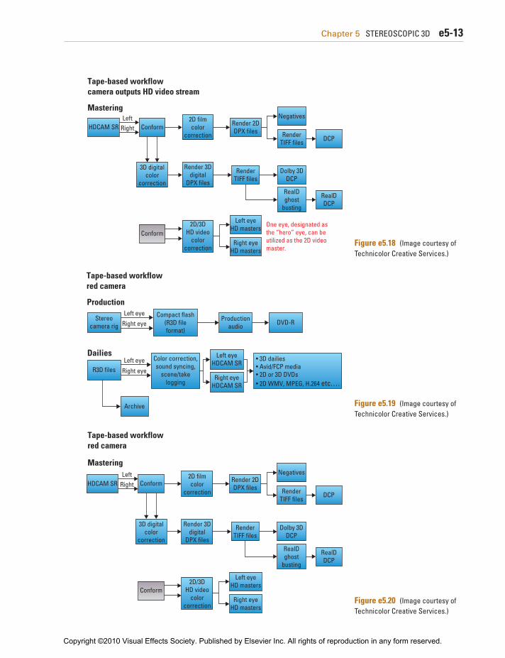
Figures e5.13 through e5.20 refl ect the options in post- production for tape-based and fi le-based workfl ows in sup-port of dailies and editorial leading up to visual effects and the fi nal conform and DI stages. These workfl ows are based on tape-based cameras (Sony F35/F900) used by Pace Digital and 3Ality and fi le-based cameras (Red, SI-2K) used by Paradise FX on several projects.
Copyright ©2010 Visual Effects Society. Published by Elsevier Inc. All rights of reproduction in any form reserved.

e5-12 Chapter 5 STEREOSCOPIC 3D
Figure e5.15 (Image courtesy of Technicolor Creative Services.)
File-based workflowred camera
Production
Dailies
Stereocamera rig
Color correction,sound syncing,
scene/takelogging
• 3D dailies• Avid/FCP media• 2D or 3D DVDs• 2D WMV, MPEG, H.264 etc. . . .
R3D files
Compact flash(R3D fileformat)
Productionaudio
Archive
Left eye
Right eye DVD-R
Left eye
Right eye
Figure e5.16 (Image courtesy of Technicolor Creative Services.)
File-based workflowred camera
MasteringR3D
archiverestore
Render 2DDPX files
Right eyeHD masters
Left eyeHD masters
LeftRight
RenderTIFF files
Dolby 3DDCP
RealDDCP
RenderTIFF files
2D filmcolor
correction
2D/3DHD video
colorcorrection
Render 3Ddigital
DPX filesRealDghost
busting
One eye, designated asthe “hero” eye, can beutilized as the 2D videomaster.
3D digitalcolor
correction
Conform
Conform
DCP
Negatives
Figure e5.17 (Image courtesy of Technicolor Creative Services.)
Tape-based workflowcamera outputs HD video stream
Production
Dailies
Stereocamera rig
Color correction,sound syncing,
scene/takelogging
• 3D dailies• Avid/FCP media• 2D or 3D DVDs• 2D WMV, MPEG, H.264 etc. . . .
HDCAM SR
Single (422) orDual (444)
HDCAM SRrecording
Productionaudio
Left eye
Right eye DVD-R
Left eye
Right eye
Copyright ©2010 Visual Effects Society. Published by Elsevier Inc. All rights of reproduction in any form reserved.
Chapter 5 STEREOSCOPIC 3D e5-13
Figure e5.18 (Image courtesy of Technicolor Creative Services.)
Tape-based workflowcamera outputs HD video stream
Mastering
Render 2DDPX files
Right eyeHD masters
Left eyeHD masters
LeftRight
RenderTIFF files
Dolby 3DDCP
RealDDCP
RenderTIFF files
2D filmcolor
correction
2D/3DHD video
colorcorrection
Render 3Ddigital
DPX filesRealDghost
busting
One eye, designated asthe “hero” eye, can beutilized as the 2D videomaster.
3D digitalcolor
correction
Conform
Conform
DCP
Negatives
HDCAM SR
Figure e5.19 (Image courtesy of Technicolor Creative Services.)
Tape-based workflowred camera
Production
Dailies
Stereocamera rig
Left eyeHDCAM SR
Right eyeHDCAM SR
Color correction,sound syncing,
scene/takelogging
• 3D dailies• Avid/FCP media• 2D or 3D DVDs• 2D WMV, MPEG, H.264 etc. . . .
R3D files
Compact flash(R3D fileformat)
Productionaudio
Archive
Left eye
Right eye DVD-R
Left eye
Right eye
Figure e5.20 (Image courtesy of Technicolor Creative Services.)
Tape-based workflowred camera
Mastering
Render 2DDPX files
Right eyeHD masters
Left eyeHD masters
LeftRight
RenderTIFF files
Dolby 3DDCP
RealDDCP
RenderTIFF files
2D filmcolor
correction
2D/3DHD video
colorcorrection
Render 3Ddigital
DPX filesRealDghost
busting
3D digitalcolor
correction
Conform
Conform
DCP
Negatives
HDCAM SR
Copyright ©2010 Visual Effects Society. Published by Elsevier Inc. All rights of reproduction in any form reserved.

e5-14 Chapter 5 STEREOSCOPIC 3D
3D Stereoscopic Conforming The most important milestone for the digital intermediate team is the stereo conform process. It is essential for the stereo con-form be tested and reviewed by the editorial team to make sure that the process is perfect. A series of initial conforming tests should be completed before and as the reels are assembled. The digital intermediate process normally breaks down the project deliverables by reels. After each reel is conformed, the 2D color correction can begin or continue if an on-set solution was utilized.
Although the fi nal deliverable is 3D, the product is always released as a 2D deliverable to accommodate the broader audi-ence. The majority of the color correction work is done in the 2D creative grade. This allows post to use the resources available in the digital intermediate software systems to treat and grade the images. The corrections are then applied to the other eye and viewed in 3D to measure and test the results.
Overall Stereo Workflow and Conforming Process Options The traditional DI assembly method is much like any fi nal con-form. An EDL is used as a reference to the image selects and the fi nished audio fi les in the AIFF format from the editorial off line as the starting point for the conform. It is very advantageous to have access to both left and right images at all times during the grading process. But not all DI systems can maintain good oper-ational performance levels in stereo mode. If good stereo asset management tools, solid stereo tools, and an experienced team are on hand, the conform and shot update process should be a relatively straightforward process.
When to Start the Post-Production Process Involving post-production during the early pre-production plan-ning stages of a 3D stereo project can be a benefi cial fi rst step in helping guide the production direction of the show. Depending on the post-production demands of the project, the feedback from post-production may in fact guide some of the production processes if clearly understood early. The post-production pro-cess can take place in parallel and be used as part of the daily review and off-line deliverables process.
The DI theater may also be utilized by production to assist in the review and development of visual effects shots throughout the post-production process. It is essential to budget adequate time to allow for the large amount of data that is generated by stereo cameras and visual effects facilities. It is also very impor-tant to allow the visual effects and data teams’ additional time to deal with the idiosyncrasies of managing a stereo pair of images on a large production.
Copyright ©2010 Visual Effects Society. Published by Elsevier Inc. All rights of reproduction in any form reserved.
Chapter 5 STEREOSCOPIC 3D e5-15
Many studios have chosen to bring some of these processes in house and have integrated them alongside their CGI workfl ow. This is more common among the larger 3D animation compa-nies who can build a direct pipeline and control the process. The facilities may even purchase their own software DI systems. This allows them to maintain creative control of their assets and main-tain control of their schedule by not being at the mercy of their DI facility and their other clients.
Other traditional post-production facilities have added new equipment and additional capability to allow for stereo post-production to take place. Stereo post-production is a rapidly evolving segment of the market that will have a large amount of growth in the next 5 years.
Testing with the post-production partner or in-house facil-ity should ideally begin before production to establish proper pipelines and establish proper review techniques for 3D dailies. Constant evaluation of the 3D stereo images through dailies reviews and visual effects reviews on a variety of displays is required. This includes reviews on a variety of displays: large theater screens, ste-reo delivery systems, and smaller home video displays.
Selecting Left or Right Eye for the Mono Master For a live-action 3D fi lm, the right eye is sometimes chosen as the primary eye or “hero” eye. Depending on the camera rig cho-sen for a particular scene, the left eye may be refl ected from the beamsplitter. The images refl ected off the beamsplitter may have lifted blacks, fl aring, or slight color distortion depending on the quality of glass used. This is a big consideration for choosing a proper stereo rig but typically more of a reality for the dailies and fi nal colorist to address. The “hero” eye or the mono master should be derived from the best image available.
Two types of workfl ows are currently available for live-action stereo projects: data-centric and tape-based workfl ows. Note that the camera choice may defi ne the workfl ow due to the fact that the camera itself may be fi le based, for example, the Red One cam-era. However, depending on budget, editorial preference, and the planned conforming and DI process, a workfl ow can be established on either tape or maintained as fi les in a data-centric workfl ow.
Any 3D stereo workfl ow should utilize metadata and time-code to keep the left and right eyes in sync with each other. It is very important for proper timecode procedures to be followed throughout the entire process to ensure that the left and right eyes maintain their sync relationship at all times. A frame off-set on a matte used for a composite on a 2D project may not be noticed during motion, but a simple frame offset between the left and right eye will not be tolerated in 3D stereoscopic images. The offset between the two eyes will be immediately “felt” when viewing the images.
Copyright ©2010 Visual Effects Society. Published by Elsevier Inc. All rights of reproduction in any form reserved.

e5-16 Chapter 5 STEREOSCOPIC 3D
The source tapes can be ingested (imported) utilizing the EDL from the off-line system to do a batch capture on the con-forming system. A set number of handle frames is normally established to allow for slight changes during the post-produc-tion process.
The ingest path for the left and the right eyes must be exactly identical. A difference in the procedure, hardware, or color path used during the ingest process may produce unacceptable stereo results. This would manifest itself by creating differences in the left and right eyes that will cause viewer fatigue.
The stereo camera image capture process inherently has left and right eye differences because of physics and imperfections in camera optics. Use of the beamsplitter to achieve specifi c interaxial offsets for image capture within 10 feet of the subject for close-ups may soften the focus and may sometimes intro-duce differences in the luminance levels between the two cam-eras, which causes viewing issues. It may be desirable to remove these left and right eye differences in a pre-processing step after the initial conform. The Foundry’s Ocula software has some tools available for left eye/right eye auto color matching.
This is also something that an assistant colorist could do before the stereo creative grade using the digital intermediate software by using tools to compare the two images to minimize the difference in color balance between the eyes.
The fi nal conform should be viewed in stereo to check for editorial inaccuracies and to make sure the stereo was ingested properly. Once the stereo ingest is complete, the workfl ow takes on similar characteristics to the data-based workfl ow.
Data Workflow A stereo data workfl ow should use timecode procedures that are identical to the tape-based workfl ow procedures. Careful data management processes should be followed to properly identify left and right eyes and maintain image continuity. Normal data workfl ow procedures should be followed with use of RAID stor-age systems and storage area networks (SANs) with proper tape backups throughout the entire process.
Standard 2D color correction techniques can be used through-out the grading process. This includes primary and secondary grading, hue and value qualifi ers, static or animated geometry, and image tracking techniques.
The mono creative grade should be done on a DCI-compliant 5 projector at 14 foot-lamberts in a completely calibrated environment
5 DCI: Digital Cinematography Initiative for Digital Projection.
Copyright ©2010 Visual Effects Society. Published by Elsevier Inc. All rights of reproduction in any form reserved.

Chapter 5 STEREOSCOPIC 3D e5-17
according to SMPTE 6 specs. Stereo creative grading can be done on a RealD projection system calibrated between 3.5 and 5 foot-lamberts as specifi ed by RealD for their projectors in the fi eld.
Mastering light-level options are currently being debated by many organizations. The new RealD XL Z-screen achieves increased light effi ciency and is able to achieve more than 12 foot-lamberts. This will be something to keep an eye on as RealD deploys the XL light doubling technology.
The ideal grading environment would have mono and stereo projection systems available and use a white screen for mono grading and the silver screen for the 3D grading. This system should be able to transition from the 2D grading environment to the 3D grading environment in less than 1 minute. This will allow a user to quickly check the stereo settings in the stereo grade to make sure that the shots look as expected.
A 3D projection system may also require ghost reduction, commonly referred to as ghost busting . Stereo ghosting is caused by ineffi ciency in the projection system and the viewing glasses. If the projector and the glasses were 100% effi cient, there would be no need for ghost reduction.
The 3D fi lms also require a stereo blending pass to minimize ghosting effects in the animation. This provides the ability to set the stereo convergence of the shots to minimize viewer fatigue and allow for good stereo continuity. In addition to the stereo blending pass, other techniques may be used such as fl oating windows. Floating windows are used to move the object in front of the screen plane or behind the screen image plane to set the depth of the scene for the viewing audience. Blending and ste-reo windows will normally animate from shot to shot to allow for proper stereo viewing continuity.
In addition, convergence changes can be made to the images by means of pixel shifting the images on the x -axis in the digital intermediate software. This along with stereo blending will allow the colorist and the stereographer to set the depth and post- production to achieve the optimum experience for the viewer.
The use of stereo disparity and depth maps such as those generated in the Ocula plug-in will allow an artist to use a stereo shifter that creates new pixels and new stereo convergence set-tings for live-action photography. This is evolving technology and is not always artifact free.
CG animated fi lms can use stereo disparity maps that are eas-ily generated with the CG process to help in the convergence
6 SMPTE: Society of Motion Picture and Television Engineers; a forum that sets stan-dards for transmission, projection, recording, storage, and archiving of images.
Copyright ©2010 Visual Effects Society. Published by Elsevier Inc. All rights of reproduction in any form reserved.

e5-18 Chapter 5 STEREOSCOPIC 3D
of images. This allows for greater manipulation, more precise rotoscoping, and increased working speed during the post- production stereo manipulation process.
2D versus 3D Grading It is best if the stereo rotoscoping process could be done utiliz-ing software intelligence or use of the stereo disparity map. This technology is currently evolving and is only used in shot-based compositing systems such as the Foundry’s NUKE software.
As these technologies mature, the use of more rotoscoping shapes and greater freedom in the stereo color correction process will become more commonplace. Currently, intricate rotoscoping must be manually offset and tracked as the image moves through 3D space.
CGI animation stereo projects have the added benefi t of ren-dering out character, background, and visual effects element mattes, which allows for greater freedom than does a live-action stereo project.
It is essential for the digital intermediate system to allow the use of mattes. In the future, systems will allow for unlimited use of mattes, which will greatly reduce the amount of manual stereo rotoscoping offsetting.
Stereoscopic color grading is normally done in addition to the mono creative grade. Warmer hues appear closer in 3D space. Cooler colors such as light green and blue appear farther away since the brain perceives these as normal background colors. The director of photography will normally use a color palette that complements the 3D stereo environment. On an animated fea-ture, the production designer will normally choose the color pal-ette and develop a color script 7 for the entire animated feature. This is complemented by a stereo script that is normally set up by the stereographer for future use.
3D Stereo RealD Mastering Considerations Stereo projects use the same approach to reel-by-reel workfl ow. Depending on the delivery schedule, there may be a request to move directly to the stereo reel immediately after delivery of a mono reel. The RealD grading environment should ideally be the same system and room as the mono grade. A silver screen will be put into place, and the RealD Z-screen will be used to create the 3D effect when viewed with the passive glasses.
7 Colors used for scene-to-scene and character design to match image depth require-ments per script.
Copyright ©2010 Visual Effects Society. Published by Elsevier Inc. All rights of reproduction in any form reserved.

Chapter 5 STEREOSCOPIC 3D e5-19
The addition of the Z-screen polarizer and passive glasses reduces the amount of light that reaches the viewer’s eyes. The RealD stereo deliverable must compensate for these additional devices needed to create the stereo effect for the viewer. As of early 2010, a RealD deliverable was mastered at 3.5 to 4.5 foot-lamberts as measured through the passive glasses. For the near future this will remain the current confi guration. The color-ist may use a LUT (lookup table) or the primary color tools to match the look of the mono DCM (Digital Cinema Master) with-out glasses, to the stereo image through the RealD system with glasses.
Geometry and Correction of Undesirable Binocular Disparity Use of tools to fi x and optimize the stereo defects and ste-reo effects, such as Foundry’s Ocula software, stereo disparity maps, and the interaxial pixel shifting, are geometry issues that need to be addressed and fi xed in post if not realized during production.
Each DI system will have its own way to manage the transition from stereo to mono. Current 3D stereo DI technology does not use stereo disparity maps, as used in the Ocular software for ste-reo compositing. For certain situations an outboard tool external to the DI system may be needed for stereo reconciliation.
Frame shifting uses x -axis frame adjustment controls that need to be able to be viewed in stereo. This is used to adjust the stereo from shot to shot for live-action stereo productions. The Quantel Pablo and DI compositing system’s additional news tools from 3D Stereoscopic Production Company 3Ality, can provide a “green = good, red = bad” stereo quality control report and tun-ing system. Stereo blending is more common in animation where virtual stereo cameras allow shot-to-shot adjustments to blend stereo depth transitions.
As with any new and emerging technologies, there are many ways to approach their use and apply these tools to an applicable project. It will depend on the project, team, talent, and gear to create a proper stereo workfl ow.
3D Stereo Deliverables Each deliverable has its own characteristics and needs proper compensation for the delivery system. The mono deliverables include fi lm, digital cinema master, and mono home video. The stereo deliverables include stereo IMAX and a RealD stereo master with ghost reduction and a Dolby stereo digital cinema master.
Copyright ©2010 Visual Effects Society. Published by Elsevier Inc. All rights of reproduction in any form reserved.

e5-20 Chapter 5 STEREOSCOPIC 3D
3D Stereo Home Video Deliverables The 3D stereo home video market is developing rapidly with a variety of systems contending for home delivery. Traditional cyan/red anaglyph and magenta/green anaglyph are existing forms of stereo home video. The deliverables for these media should be optimized for the delivery system and judged on a vari-ety of displays with the associated glasses to ensure their enjoy-ment by the largest number of viewing audience members.
Current home video active glasses technology includes checkerboard, left right split, or stereo interlaced images. These technologies use active glasses with an infrared emitter to syn-chronize the glasses. New technologies will continue to emerge for the home video market.
The SMPTE is also actively trying to set a standard for deliv-ery, display, and formatting of 3D stereo video. Once set, this will open the fl oodgates for manufacturing to proceed with product development and shipment. In the spring of 2010, more product offerings in the consumer electronics space emerged.
References 1. Wikipedia: Source of Defi nitions and Anaglyph Images 2. RealD 3D specs and Roadmap: www.reald.com/Content/Cinema-Products
.aspx • IMAX 3D Film and 3D Digital PDF • Home 3D Technologies and recent SMPTE standards PDF • Images courtesy of RealD provided by Matt Cowan, Chief Scientifi c Offi cer
at RealD, from an IBC presentation, dated 11/15/07, “Stereoscopic 3D: How It Works”
3D Stereoscopic links and short descriptions, spec sheets of available stereo DI systems • Quantel Pablo www.quantel.com/list.php?a=Products&as=
Stereo3D • da Vinci Resolve www.davsys.com/davinciproducts.html • Autodesk Lustre www.autodesk.com • Assimilate Scratch www.assimilateinc.com • Iridas Speedgrade www.speedgrade.com • Digital Vision NuCoda www.digitalvision.se/products/index
.htm • RealD www.reald.com • Technicolor Creative Services www.technicolor.com
Copyright ©2010 Visual Effects Society. Published by Elsevier Inc. All rights of reproduction in any form reserved.