Embed Size (px)
Citation preview

5th IAHR International Junior Researcher and Engineer Workshop on Hydraulic
Structures (IJREWHS) Hydrodynamic Investigation of Free-Surface Turbulent Vortex
Flows with Strong Circulation in a Vortex Chamber
Spa, Belgium – 28-30 August 2014
S. Mulligan*, J. Casserly2, R. Sherlock3
CERIS, Institute of Technology ,Sligo (Ireland)
2 Department of Civil Engineering and Construction (IT Sligo)
3School of Science (IT Sligo)
*email : [email protected]

Overview of Presentation
Spa, Belgium 28-30 August 2014
01/23
1. Introduction – Vortex Flow
2. Hydrodynamics of Vortex Flow
3. Numerical Modelling using ANSYS CFX
4. Overview of Numerical Model
5. Physical Model
6. Results
7. Discussion
8. Concluding Remarks
5th IJREWHS

1. Introduction – Vortex Flow
Spa, Belgium 28-30 August 2014
02/23
• Previous Studies - Weak air-core vortex flows
• Previous investigations carried out to avoid or
eradicate their formation at intakes
• Minimum submergence or critical depth is
determined
Pump Intake vortex Formation
(http://www.pumpfundamentals.com/)
Hydropower Intake Vortex (The Rance
Tidal Hydropower Station) Schematic of Intake Vortex (Illustration by Author)
5th IJREWHS

1. Introduction – Vortex Flow
Spa, Belgium 28-30 August 2014
03/21
5th IJREWHS
• In recent years, technologies have began employing vortex flow behaviour for various hydro-
industrial applications
• Mixing tanks, hydro cyclone separators, vortex drop shafts and hydro electric power applications
• Generates a sizeable tangential velocity field and fully developed and relatively constant air-core
diameter
• Flow field is complex, three dimensional, multiphasic (air/water/particles) and highly turbulent in
nature
• Requires numerical simulation to quantify key flow parameters and carry out optimisation
parameters and to carry out system optimisation
Hydro Cyclone Separator
(www.bmind.in) Construction of the Tso Kung Tam Vortex
Dropshaft (http://www.dsd.gov.hk/) Vortex air core (IT Sligo)
1. Introduction – Vortex Flow
Spa, Belgium 28-30 August 2014
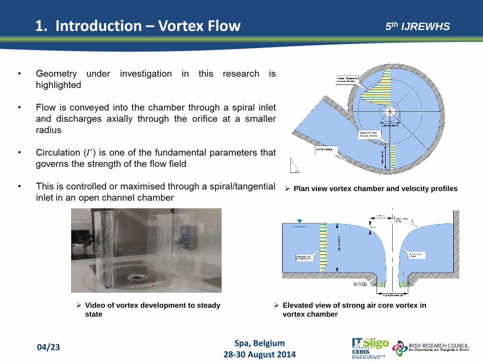
04/23
5th IJREWHS
Elevated view of strong air core vortex in
vortex chamber
Plan view vortex chamber and velocity profiles
Video of vortex development to steady
state

1. Introduction – Project Aims
Spa, Belgium 28-30 August 2014
05/23
5th IJREWHS
Thesis Title - Hydrodynamic Investigation of Free-Surface Turbulent Vortex Flows with Strong Circulation in a Vortex Chamber
Investigate the relevant flow variables that govern vortex flow behaviour
Quantify the relationships for dependent parameters
Provide a general outlook on the three dimensional velocity profiles
Validate a numerical model for strong vortex flow simulation and analysis ANSYS CFX

2. Hydrodynamics of Vortex Flow
Spa, Belgium 28-30 August 2014
06/23
5th IJREWHS
Author Equation
Rankine Model
Scully Model
Vatistas n = 2 Model
Cross section of vortex chamber highlighting velocity models

3. Numerical Modelling using ANSYS CFX
Spa, Belgium 28-30 August 2014
07/23
5th IJREWHS
Geometry creation or external geometry
input (e.g. AutoCAD ACIS file)
Mesh generation or external mesh file
importation
Solver setup (physical model, boundary
conditions, turbulence models etc.)
Monitor solution and equation residuals
CFX post analysis (vectors, streamlines
etc.)
• ANSYS CFX uses the Finite Volume Method to model and simulate fluid flows in a range of
applications.
• It has a reputation to be focused on applications in turbo machinery
• The solver emphasises on the widely tested shear stress transport (SST) and Reynolds stress
models which have particular advantages in fidelity when separated flows, free shear and rapid
streamline curvature is experienced

4. Overview of Numerical Model
Spa, Belgium 28-30 August 2014
08/23
5th IJREWHS
General Multiphase Modelling
4. Overview of Numerical Model
Spa, Belgium 28-30 August 2014
09/23
5th IJREWHS
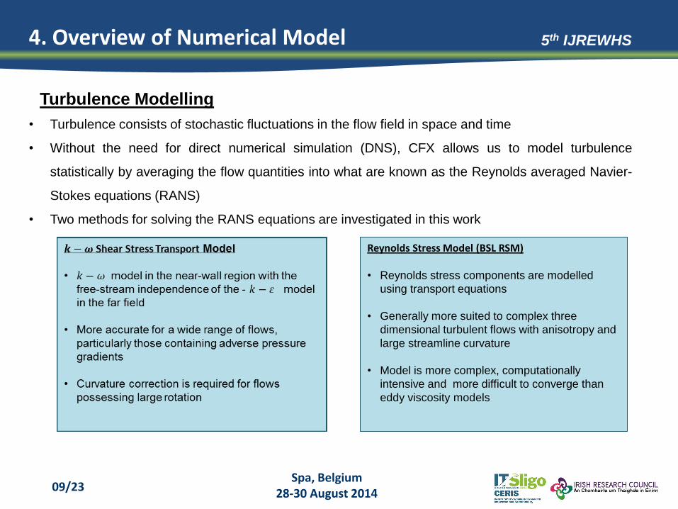
Reynolds Stress Model (BSL RSM)
• Reynolds stress components are modelled
using transport equations
• Generally more suited to complex three
dimensional turbulent flows with anisotropy and
large streamline curvature
• Model is more complex, computationally
intensive and more difficult to converge than
eddy viscosity models
• Turbulence consists of stochastic fluctuations in the flow field in space and time
• Without the need for direct numerical simulation (DNS), CFX allows us to model turbulence
statistically by averaging the flow quantities into what are known as the Reynolds averaged Navier-
Stokes equations (RANS)
• Two methods for solving the RANS equations are investigated in this work
Turbulence Modelling

4. Overview of Numerical Model
Spa, Belgium 28-30 August 2014
10/23
5th IJREWHS
• Three test cases are analysed for
mass flows (flowrates) at the inlet
• Outlet set to opening with
entrainment (direction of flow is
unknown) with a relative pressure of
0
• Top of chamber is set to opening
with relative pressure of 0
• Walls modelled with a no slip
boundary condition
• Turbulence intensity set to 10% at
inlet and opening
Boundary Details
A Inlet Boundary type: Mass flow normal to boundary Other details: 10% turbulence intensity
Test Cases
A1 0.725kg/s H/d = 1 = 67 mm
A2 1.677kg/s H/d = 2 = 134 mm
A3 3.111kg/s H/d= 3.5 = 235 mm B Outlet Boundary type: Opening with entrainment
Other Details: Zero relative pressure, zero gradient turbulence intensity
C Walls Boundary type: No-slip smooth wall boundary D Opening Boundary type: Opening with pressure and direction
Other details: Zero relative pressure, 10% turbulence intensity
Boundary conditions
Test Cases

4. Overview of Numerical Model
Spa, Belgium 28-30 August 2014
11/23
5th IJREWHS
Unstructured and structured mesh cases investigated using the SST model (due to robustness)
Unstructured Tetrahedral
• Coarse (100k cells, 10mm min size) –
Fine (499k cells, 5mm min size)
• Tetrahedral elements sized using
proximity and curvature
• Inflation applied at boundaries
• Difficult to refine mesh in the near field
region without using mesh adaptation
Structured Hexahedral
• Coarse (100k cells, 6mm min size) – Fine (499k
cells, 1.5mm min size)
• Domain separated into three multiple parts
• Mesh is dense at outlet and increased in size in the
far field
• Inflation applied at boundaries
• Efficient use of cells and possible to refine mesh in
the near field
Plan and cross section of finely unstructured mesh Plan and cross section of finely structured mesh
Mesh Details

4. Overview of Numerical Model
Spa, Belgium 28-30 August 2014
12/23
5th IJREWHS
Turbulence Modelling

5. Overview of Physical Model
Spa, Belgium 28-30 August 2014
13/23
5th IJREWHS
Illustration of vortex test rig
Physical model investigated in this work
Inlet
Orifice
Camera
viewport
Spiral
casing
• Test facility designed at IT Sligo to physically
model vortex flows
• Consist s of an open top tank resting over a
hydraulic bench and reservoir
• Tank can be adapted with various geometric
boundaries for a range of open channel vortex
flow cases
• Physical model – Spiral, open channel vortex
chamber with a 67mm outlet
• Water circulated through apparatus during
testing (0 - 3.5l/s) and is monitored using a
magnetic flow meter
• A depth gauge is employed to traverse the flow
field and map the physical water surface
General Overview

5. Overview of Physical Model
Spa, Belgium 28-30 August 2014
14/23
5th IJREWHS
PTV Image highlighting tracer
particles entering the domain
Laser light sheet profile passing through
vortex during image acquisition
• Measurement of tangential and radial velocity
components of the flow field
• Neutrally buoyant particles are tracked at
various horizontal planes (z/Hin)
• Illumination provided by an Nd:YAG laser
pulsing at 10-30Hz passed through light
sheet optics
• Light sheet is imaged subsequently using
high speed camera housed on the tank
underside
• Velocity vectors are determined from
displacements determined in particle tracks
Particle Tracking Velocimetry (PTV)

6. Results
Spa, Belgium 28-30 August 2014
15/23
5th IJREWHS
0
0.1
0.2
0.3
0.4
0.5
0.6
0.7
0.8
0.9
1
0 0.5 1 1.5 2 2.5 3 3.5
V𝝷 (m/s)
r/do
Experimental
Vatistas n = 2
SST Coarse Mesh
SST Medium Mesh
SST Fine Mesh
SST with Curvature Correction
BSL Reynolds Stress Model
Vort
ex C
ore
Sensitivity of water surface profile
Sensitivity of tangential velocity profile
• Unstructured mesh is unsuitable for vortex
flow analysis due to excessive numerical
diffusion error (false diffusion)
• Solution becomes mesh independent at fine
mesh scenario (490k Elements, 1.5mm
minimum cell size)
• Curvature correction significantly improves
the shear stress transport model particularly at
the vortex core
• Most suitable model was found to be the BSL
Reynolds stress model
• Candidate turbulence model used for further
modelling
Solution Sensitivity
6. Results
Spa, Belgium 28-30 August 2014
16/23
5th IJREWHS
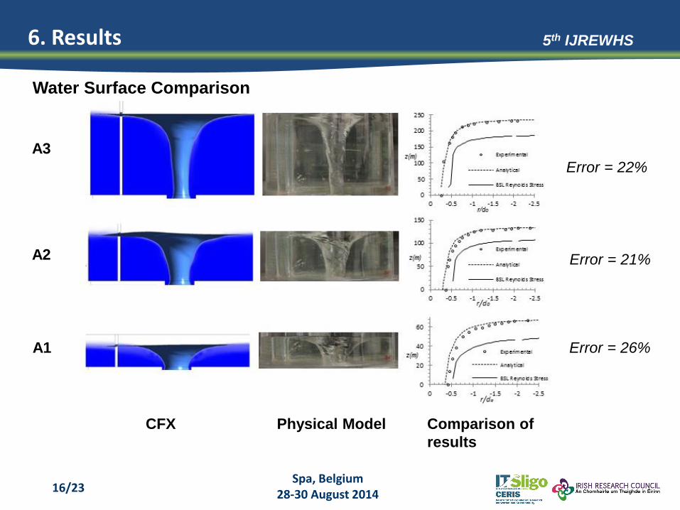
A3
A2
A1
CFX Physical Model Comparison of
results
Error = 22%
Error = 21%
Error = 26%
Water Surface Comparison

6. Results
Spa, Belgium 28-30 August 2014
17/23
5th IJREWHS
0
0.2
0.4
0.6
0.8
1
1.2
0 1 2 3
V𝝷
(m/s)
r/do
Experimental
Vatistas n=2
BSL ReynoldsStress
Vo
rtex
Co
re
Γ = 0.2144 m²/s
0
0.1
0.2
0.3
0.4
0.5
0.6
0.7
0.8
0 1 2 3r/do
Experimental
Vatistas n=2
BSL ReynoldsStress
Vo
rtex
Co
re
Γ = 0.229m²/s
0
0.1
0.2
0.3
0.4
0.5
0.6
0.7
0.8
0 1 2 3r/do
Experimental
Vatistas n=2
BSL ReynoldsStress
Vo
rtex
Co
re
Γ = 0.219m²/s
Tangential velocity profile
and water superficial
velocity for z/Hin = 0.26
Tangential velocity profile
and water superficial
velocity for z/Hin = 0.56
Tangential velocity profile
and water superficial
velocity for z/Hin = 0.75
Tangential Velocity Comparison

6. Results
Spa, Belgium 28-30 August 2014
18/23
5th IJREWHS
0
0.2
0.4
0.6
0.8
1
0 0.1 0.2 0.3 0.4
z/Hin
Vin (m/s)
Experimental
BSL ReynoldsStress Model
Vorticity field at the
vortex core
Inlet velocity profile
comparison
Visual comparison of water surface waves at the vortex core
Surface waves
• CFX post indicates that the vorticity field
is zero everywhere except for at a small
region at the orifice and water surface
• Tangential velocity curves also highlight
that there is no significant reduction of
tangential velocity at the vortex core as
suggested in previous models
• Therefore flow is fully irrotational i.e. no
viscous core
• Inlet velocity profile is overestimated
using the CFX BSL Reynolds stress
model
• Recognisable similarities in surface
wave formations
Other Results

7. Discussion
Spa, Belgium 28-30 August 2014
19/23
5th IJREWHS
• Unstructured grid is unsuitable for modelling of vortex flows
• Grid sensitivity analysis is a crucial, mandatory step in vortex modelling. In
this example a case for mesh independency is found when using a fine
mesh with a minimum cell size of 1.5mm at the outlet region
• Application of curvature correction (production multiplier of 1.25) makes a
significant improvement to the overall solution of the SST model
• Baseline Reynolds stress model (BSL RSM) was found to be the most
suitable candidate for further modelling

7. Discussion
Spa, Belgium 28-30 August 2014
20/23
5th IJREWHS
• The CFX model presents a good solution for the position of the vortex core
and the general shape of the free surface including the formation of surface
waves
• However it fails to resolve the position of the free surface by significantly
under predicting in all three cases; 22%, 21% and 26% for A3, A2 and A1
respectively
• The RSM shows fair to moderate agreement when compared to the
tangential velocity data in all cases by over predicting the velocity profile
• The Vatistas n = 2 analytical solution proves to agree well with experimental
data in all cases
• Limitations due to uncertainty of the models performance at the tank
boundaries and close to the water surface. The model also exhibits
axisymmetric behaviour.

7. Discussion
Spa, Belgium 28-30 August 2014
21/23
5th IJREWHS
Reasons for inaccuracies in the numerical
model?
• Errors in obtaining physical data are
concluded to be minimal
• Numerical uncertainty may arise from
discretisation error (truncation & diffusion
error), boundary conditions, improper time
step etc.
• Numerical uncertainty was practically
reduced/minimized during sensitivity analysis
• Failure of convergence and evidence of
fluctuating residuals and monitor point
• It is possible that unsteady features in the
flow system are preventing further resolution
of the numerical model (surface and sub
surface waves)
Example of fluctuating mass and momentum
residuals plot for case A2

7. Discussion
Spa, Belgium 28-30 August 2014
22/23
5th IJREWHS
Water surface (isosurface water volume
fraction 0.5) and velocity vectors in CFX
post
Discharge in a vortex drop shaft
structure (Hohl)
• Further transient analysis of flow system
is required
• Limitations of the particle tracking
velocimetry setup obstructs the
examination of tangential velocities in the
near field (vortex core)
• Work will be progressed in this direction
to further validate the numerical and
analytical model
• Results from a fully validated CFD model
is invaluable for the design and
optimisation of such structures (sizing
structures, velocities, pressures etc.)
• CFX bench mark report to be completed
in 2015

Spa, Belgium 28-30 August 2014
23/23
Thank you for your attention!
5th IJREWHS
![[JUNIOR SCIENTIFIC RESEARCHER JOURNAL] JSR · [JUNIOR SCIENTIFIC RESEARCHER JOURNAL] JSR 16 Vol. IV │ No. 1 │ May 2018| categorized as one of the countries that low law enforcement](https://img.pdfslide.net/doc/110x75/5f2d65e6786a7c21c833a915/junior-scientific-researcher-journal-jsr-junior-scientific-researcher-journal.jpg)