Embed Size (px)
Citation preview

1
5V Crimp Installation
Manual

2
Available in different colors. 5V Crimp panels ideal for
residential and agricultural. All colors are Energy Star rated.
Also available in Galvalume.
5V Crimp Panel Product Information
The 5V Crimp panel features 24” of coverage; 5 ribs at 12” and 24” on
center with 3/8” rib height.
Applications over 15/32 plywood. Approval #: FL11671.2
Available in 26 gauge and *24 gauge
Minimum Roof Slope: 1/4:12 with Lap Sealant OR 2:12 without sealant
Finish Warranty: 45 year Limited
Galvalume Warranty: 25 year
*(minimum order required for 24 gauge material)
NOTE: If you application varies from the application shown here, please advise your sales
representative for job-specific accommodations.

3
IMPORTANT NOTICE This manual serves as a guide to proper installation of the 5V Crimp
panel.
It is important to check the local building codes, HOA regulations, etc.
before installing a metal roof.
If you have any questions regarding the proper installation of the 5V
Crimp panel, please contact your Mid Florida Metal Roofing Supply
representative.
SAFETY
Tools recommended: screw gun, snips, nibbler, tape measure, drill bits,
gloves, chalk/string line, safety harnesses, etc.
Use extreme caution at all times when installing metal roofing.
Never walk on a wet or unfastened metal roof panel.
Failure to adhere to proper roofing safety guidelines can cause serious
injury or death. Refer to OSHA guidelines for safety requirements.
STORAGE
If metal panels are not to be installed immediately, keep stored in a
dry location. Keep metal panels off of the ground by placing the
panels on wood.
Any moisture trapped between panels can cause water stains
damage to the paint, which can affect the life expectancy of your
roof.

4
Flashing Details
Refer to flashing profiles for dimensions. Please note, modified
or custom flashing are available upon request!

5
Installation Tips
The order in which this installation manual is read, is the order in which
proper installation should occur. If you have any questions, please
contact your Mid Florida Metal Roofing Supply representative.
Underlayment installation should start at the eave of the roof and
continue along the eave. The general overlap for underlayment is 4”.
Please refer to Florida Building codes for specific installation instruc-
tions. Mid Florida Metal Roofing Supply recommends, and stocks, High
Temp Peel and Stick or Midstate Synthetic Underlayment.
Field cutting material can be done with hand snips, nibblers, and/or
shears,. Any cutting should be completed on the ground and not
above other panels or roof. This will help prevent the accumulation
of metal debris that can cause damage to the paint. Please make
sure to brush/clean off the entire roof surface once installation is com-
pleted to prevent any issues from leftover shavings.
*For your convenience Mid Florida Metal Roofing Supply stocks
(and recommends) the following:
Hand Snips
Hand Seamers/Folding Tools
Nibblers

6
5V Crimp Eave Detail
TIPS:
Attach the drip edge or eave trim to the decking with trim screws or
Pancake screws at 24” on center.
Once completed, and before installing panels, install inside closure strips
to the top of the eave trim. *Note: it is recommended to apply butyl tape
to both sides of the closure strips for a weather tight fit.
It is recommended that panels be installed flush to the drip edge.
If requested, post trim or fascia trim can also be applied to cover existing
fascia board. Custom drip edge can also be ordered to extend over the
fascia board. *Ask your sales representative for pricing and availability.

7
5V Crimp Valley Detail
TIPS:
When installing valley flashing, start at the bottom (remember to allow for
overhang as you’ll need to cut the valley flashing back to meet eave
line—if you plan on a 3” overhang for your panels, overhang the valley by
at least 3” as well) and attach with 1” trim screws every 24” on center.
Apply Direct Seal on top of the valley flashing allowing at least 3-1/2”
inches from the edge of the panel to the center of the valley flashing.
You will fasten the roof panels using 1-1/2” ZAC Woodscrews at 6 per
panel. (See page 8)
NOTE: The general overlap for flashing is 4”

8
Screw Pattern
5V Crimp Panel Standard Pattern
5V Crimp Panel End/Valley Pattern
*We recommend using Premium ZAC Woodscrew fasteners for
your metal roof!

9
Proper Screw Installation
TIPS:
FOR BEST RESULTS: Predrill 5V Crimp panels upside down in the valley of the ribs.
Predrilling the metal panels on the ground can allow for easier screw installation. This
also prevents any metal shavings from accruing on the roof which can cause issues
later.
Please see the diagram below for proper screw seating. Screws that are not proper-
ly seated can cause leaks and other issues with your roof.

10
5V Crimp Transition Detail
TIPS:
Once bottom roof panels are installed, install outside closures.
Then attach transition flashing as shown. (Note that the hemmed end goes
on top of the panel allowing the flat portion to sit underneath the top pan-
els.)
Install inside closures (Remember: Butyl tape is recommended to be ap-
plied to both the top and the bottom of the closures!)
Install top panels screwing through the closure strips to hold in place.
See Page 9 for panel end screw pattern.

11
5V Crimp Endwall Detail
TIPS:
Once panels are installed, install outside closures at the point where the
endwall flashing will be fastened down.
The top edge of the endwall can be secured in a few different ways.
Generally it is tucked under the house siding. However, in cases where
there is no siding, counterflashing can be added as another form of pro-
tection. Counterflashing also provides a more finished look. See Flashing
Profiles #34
In some cases, when counterflashing cannot be added, the endwall flash-
ing can be modified to allow a caulk edge where permathane sealant
can be used.

12
5V Crimp Sidewall Detail
TIPS:
Install butyl tape along the bottom edge of the sidewall flashing.
Once sidewall is in place, fasten using Premium ZAC Woodscrews.
Be sure to apply your butyl tape sealant along the top edge of the side-
wall where the fasteners will be installed. This creates your weathertight
seal.
As with endwall flashing, counterflashing can be added here. If pre-
ferred, a caulk edge can be modified as well.

13
5V Crimp Rake/Gable Detail
TIPS:
Install butyl tape along the inside of the flat 1/2” that will be fastened to the
top of the panel.
Start installation at the eave and allow 1” - 2” of overhang that can be cut
and folded down for a finished look.
Fasteners can be installed along fascia side of gable end for added
security, but is not required.

14
5V Crimp Hip/Ridge Detail
HIPS-
Metal panels that meet at the hips should be cut close to hip point, but not
touching.
Apply Direct Seal along panels where the hip cap edges will be fastened.
Start at the bottom of the hip when installing hip flashing, remember to allow overhang for
bending which will match panel overhang.
Attached hip flashing with Premium ZAC SDS 1-1/2” screws at each rib along the flashing.
RIDGES-
There are two applications for the ridge cap flashing: vented and non-vented.
For non-vented ridges, install outer closures (with butyl tape on both top and bottom) and fas-
ten cap with Premium ZAC SDS 1-1/2” screws at each rib.
For vented ridges, panels at the peak must leave at least a 2-4” gap between them for best
ventilation. Razorback Ridgevent should be installed in place of outer closures.
Remember to leave enough overhand to cut and bend ends t o create a finished look.
15
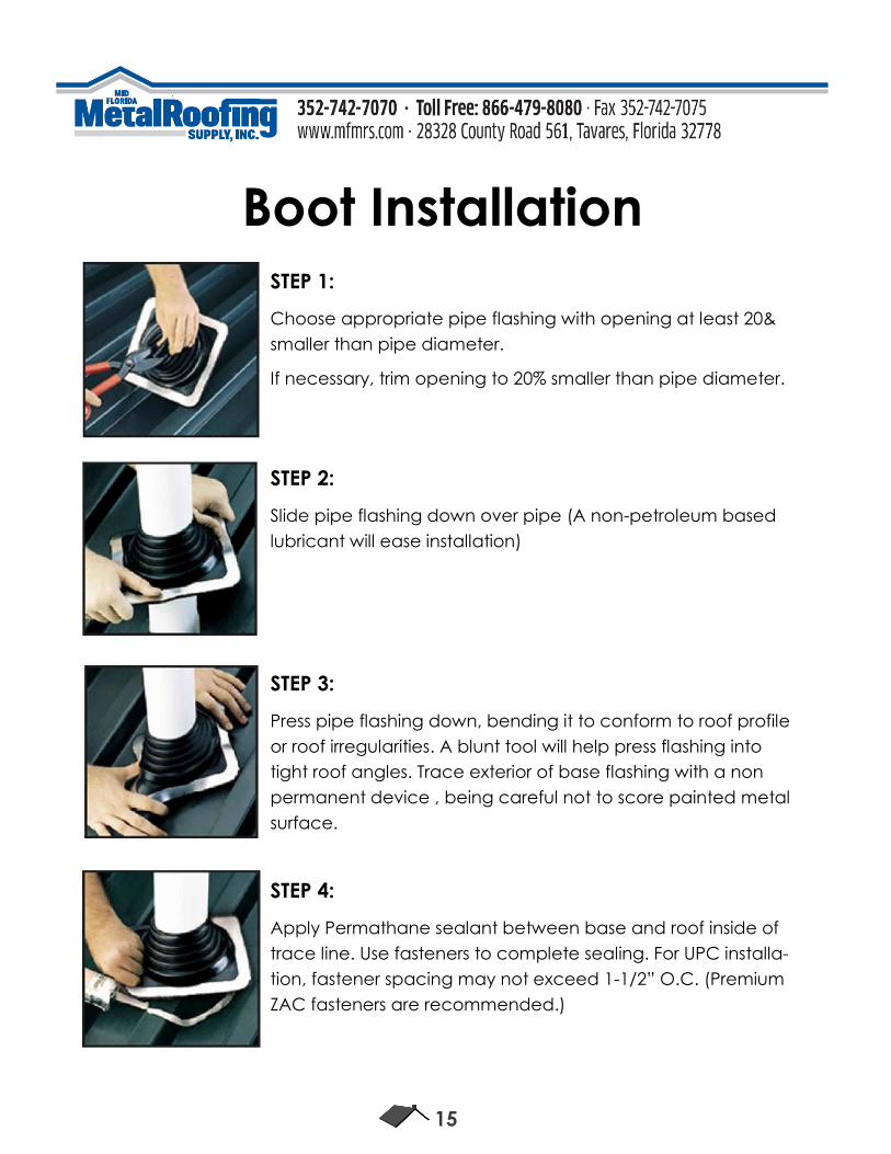
Boot Installation STEP 1:
Choose appropriate pipe flashing with opening at least 20&
smaller than pipe diameter.
If necessary, trim opening to 20% smaller than pipe diameter.
STEP 2:
Slide pipe flashing down over pipe (A non-petroleum based
lubricant will ease installation)
STEP 3:
Press pipe flashing down, bending it to conform to roof profile
or roof irregularities. A blunt tool will help press flashing into
tight roof angles. Trace exterior of base flashing with a non
permanent device , being careful not to score painted metal
surface.
STEP 4:
Apply Permathane sealant between base and roof inside of
trace line. Use fasteners to complete sealing. For UPC installa-
tion, fastener spacing may not exceed 1-1/2” O.C. (Premium
ZAC fasteners are recommended.)

16
Custom Trim
Mid Florida Metal Roofing Supply can create custom trim designs to meet your
specific needs.
If you would like to request custom trim, please provide the following:
1. A profile drawing of the trim.
2. All measurements, including hems.
3. Specify pitch or degree that the angle is needed.
4. Indicate the color side of the trim.
(SEE ABOVE)
17