Embed Size (px)
Citation preview

1B-RF-ASI-IP-TS-MX
User Manual
6 Ch RF + 2 Ch ASI Over IP DVB
Multiplexer

DIRECTORY
CHAPTER 1 PRODUCT OUTLINE ............................................................................ 1
1.1 OUTLINE .................................................................................................................. 1
1.3 PRINCIPLE CHART ............................................................................................... 2
1.4 SPECIFICATIONS ................................................................................................... 2
1.5 APPEARANCE AND DESCRIPTION ................................................................... 3
CHAPTER 2 INSTALLATION GUIDE ....................................................................... 5
2.1 ACQUISITION CHECK .......................................................................................... 5
2.2 INSTALLATION PREPARATION ......................................................................... 5
2.3 WIRE’S CONNECTION ......................................................................................... 7
2.4 SIGNAL CABLE CONNECTION .......................................................................... 7
CHAPTER 3 OPERATION ......................................................................................... 10
3.1 INITIALIZING ........................................................................................................11
3.2 GENERAL SETTING ............................................................................................ 12
CHAPTER 4 TROUBLESHOOTING ........................................................................ 21
RF over IP Multiplexer1B-RF-ASI-IP-TS-MX
www.questtel.com [email protected]

Chapter 1 Product Outline
1.1 Outline
1B-RF-ASI-IP-TS-MX DVB-S2 Tuner Input Multiplexer is the latest demodulation and
multiplexing device for digital TV broadcasting head-end system. Different from normal
multiplexer,
this multiplexer has 2 ASI inputs, supports 6 tuner inputs
(ISDB-T/DVB-C/S/S2/T/ISDB-T optional), two separate ASI output ports and one DATA
port for two separate gigabit IP outputs. In other words, It can multiplex the RF signals
from satellite into the output ports via the 6 tuners, also it can multiplex up to 2 channels
ASI input MPTS into the output transport stream (MPTS). In other words, one Tuner Input
Multiplexer can work as 6 standalone FTA IRD and two separate ASI output multiplexer.
In conclusion, its high integration and cost effective design make this device widely used
in the Next Generation of CATV Broadcasting system.
1.2 Features
Fully complies with ISO13818 and EN300468 standard
Integrated demodulating and multiplexing functions
6 DVB tuner inputs and 2 ASI inputs
MPEG-2 and mpeg-4 transport stream re-multiplexing
SPTS and MPTS code stream multiplexing
Supports accurate PCR and PID re-mapping
Two groups( each group has 2 channels) separate TS output
Two channels Gig IP output (the mirrors of the 2 ASI outputs)
Supports PSI/SI editing
Supports huge buffer memory and resists unexpected code stream
Supports multiplexing the same program to all the output channels
Alarming function
Supports network remote upgrading
Full-size LCD display and NMS operation
www.questtel.com [email protected]
RF over IP Multiplexer1B-RF-ASI-IP-TS-MX

1.3 Principle Chart
Tuner->TS 1
Tuner->TS 2
Tuner->TS 3
ASI->TS 8
MUX 1
Tuner->TS 6
ASI->TS 7 MUX 2
ASI output
ASI output
IP output
IP output
1.4 Specifications
Input interface Tuner
6 channels (ISDB-T/DVB-C/S/S2/T optional)
ASI 2 channels (Up to 214Mbps per channel)
Re-multiplex
MPEG-2 TS re-multiplex
PID re-mapping ( auto/manual optional)
PCR correction
Automatic generating PSI/SI table
Input Packet format 204/188 self-adaption
Output port ASI
2 separate groups outputs (each group has 2 channels)
IP 2 channels separate Giga IP output
PID
Output range 0000—1FFF
PID transparent Any PID transparent and mapping achievable
Amount of output PID per input
256 ( at most)
NMS port Ethernet port 10/100M
Miscellaneous Demission (W *L*H) 482mm×410mm×44mm
www.questtel.com [email protected]
RF over IP Multiplexer1B-RF-ASI-IP-TS-MX

Weight 4kg
Temperature 0~45℃(operation),-20~80℃(storage)
Power supply AC 110V±10%, 50/60Hz or AC 220V±10%, 50/60Hz
Consumption ≈18W
1.5 Appearance and description
Front panel Illustration:
Indicator area: All the indicators will light on when 1B-RF-ASI-IP-TS-MX multiplexer works
at its current mode.
1 LCD Display
2 Indicators
Power Indicator
Alarm Indicator
Tuner 1-6: when the input signal of tuner 1-6 is locked, the lighter
is green which otherwise becomes red.
ASI 1-2: TS input of port 1-2. When the input stream is normal, the
lighter is green which otherwise becomes orange
3 UP/ DOWN /LEFT/RIGHT Key
4 ENTER Key
5 MENU Key
6 LOCK Key
www.questtel.com [email protected]
RF over IP Multiplexer1B-RF-ASI-IP-TS-MX

Rear panel Illustration:
7
RF IN &
LOOP OUT
RF IN 1: Channel 1
LOOP OUT 1: Channel 1
RF IN 2: Channel 2
LOOP OUT 2: Channel 2
RF IN 3: Channel 3
LOOP OUT 3: Channel 3
RF IN 4: Channel 4
LOOP OUT 4: Channel 4
RF IN 5: Channel 5
LOOP OUT 5: Channel 5
RF IN 6: Channel 6
LOOP OUT 6: Channel 6
ASI IN ASI 1: TS input port 1
ASI 2: TS input port 2
8 ASI output ports: Group A & Group B
9 GE port
10 NMS Ethernet Port ( 10-100Mbps)
11 Power switch, fuse, socket
12 Grounding pole
www.questtel.com [email protected]
RF over IP Multiplexer1B-RF-ASI-IP-TS-MX

Chapter 2 Installation Guide
2.1 Acquisition Check
When user opens the package of the device, it is necessary to check items according to packing
list. Normally it should include the following items:
1B-RF-ASI-IP-TS-MX DVB-S2 Tuner Input Multiplexer
User’s Manual
ASI Cable
Power Cord
If any item is missing or mismatching with the list above, please contact local dealer.
2.2 Installation Preparation
When users install device, please follow the below steps. The details of installation will be
described at the rest part of this chapter. Users can also refer rear panel chart during the
installation.
The main content of this chapter includes:
Checking the possible device missing or damage during the transportation
Preparing relevant environment for installation
Installing multiplexer
Connecting signal cables
Connecting communication port (if it is necessary)
2.2.1 Device’s Installation Flow Chart Illustrated as following:
Connecting GroudingWire and
PowerCord
Acquisition Check
Fixing Device
Setting Parameter
Running Device
Connecting Signal Wire
2.2.2 Environment Requirement
www.questtel.com [email protected]
RF over IP Multiplexer1B-RF-ASI-IP-TS-MX

Item Requirement
Machine Hall Space
When user installs machine frame array in one machine hall,
the distance between 2 rows of machine frames should be
1.2~1.5m and the distance against wall should be no less than
0.8m.
Machine Hall Floor
Electric Isolation, Dust Free
Volume resistivity of ground anti-static material:
1X10⁷~1X10
10,Grounding current limiting resistance: 1M
(Floor bearing should be greater than 450Kg/㎡)
Environment
Temperature
5~40℃(sustainable ),0~45℃(short time),
installing air-conditioning is recommended
Relative Humidity 20%~80% sustainable 10%~90% short time
Pressure 86~105KPa
Door & Window Installing rubber strip for sealing door-gaps and dual level
glasses for window
Wall It can be covered with wallpaper, or brightness less paint.
Fire Protection Fire alarm system and extinguisher
Power
Requiring device power, air-conditioning power and lighting
power are independent to each other. Device power requires
AC power 220V 50Hz. Please carefully check before running.
2.2.3 Grounding Requirement
All function modules’ good grounding is the basis of reliability and stability of devices.
Also, they are the most important guarantee of lightning arresting and interference
rejection. Therefore, the system must follow this rule.
ASI cable’s outer conductor and isolation layer should keep proper electric conducting
with the metal housing of device.
Grounding conductor must adopt copper conductor in order to reduce high frequency
impedance, and the grounding wire must be as thick and short as possible.
Users should make sure the 2 ends of grounding wire well electric conducted and be
antirust.
www.questtel.com [email protected]
RF over IP Multiplexer1B-RF-ASI-IP-TS-MX

It is prohibited to use any other device as part of grounding electric circuit.
The area of the conduction between grounding wire and device’s frame should be no less
than 25mm2.
2.2.4 Frame Grounding
All the machine frames should be connected with protective copper strip. The grounding wire
should be as short as possible and avoid circling. The area of the conduction between
grounding wire and grounding strip should be no less than 25mm2.
2.2.5 Device Grounding
Connecting the device’s grounding rod to frame’s grounding pole with copper wire.
2.3 Wire’s Connection
The grounding wire conductive screw is located at the right end of rear panel, and the power
switch, fuse, power supply socket is just beside ,whose order goes like this, power switch is on
the left ,power supply socket is on the right and the fuse is just between them.
Connecting Power Cord
User can insert one end into power supply socket, while insert the other end to AC power.
Connecting Grounding Wire
When the device is solely connected to protective ground, it should adopt independent way,
say, share the same ground with other devices. When the device adopts united way, the
grounding resistance should be smaller than 1Ω.
Caution:
Before connecting power cord to 1B-RF-ASI-IP-TS-MX multiplexer, user should set the
power switch to “OFF”.
2.4 Signal Cable Connection
The signal connections include the connection of input signal cable and the connection of
output signal cable. The details are as follows:
2.4.1 ASI In and ASI out connection:
www.questtel.com [email protected]
RF over IP Multiplexer1B-RF-ASI-IP-TS-MX

ASI Input Connection
User can find ASI input port on the device according to connector mark described in the rear
panel illustration, and then connect the ASI cable (in the accessories). One end is connected to
the Multiplexer’s ASI input port, while the other end is connected to Encoder’s ASI output port
or ASI output port of other equipment.
ASI Output Connection
User can find ASI output port on the device according to connector mark described in the rear
panel illustration, and then connect the ASI cable (in the accessories); one end is connected to
the Multiplexer’s ASI output port and the other end to the Modulator’s ASI input port or ASI
input of other equipment. Multiplexer’s ASI cable illustrated as follows:
2.4.3 RF IN and LOOP OUT connection:
Users can find the RF IN and LOOP OUT interface on the device according to the connector
mark described on the rear panel illustration, and then connect the cable. One end is connected
to the RF IN interface of the tuner multiplexer while the other end is connected to the satellite
signal source equipment or LOOP OUT interface of the previous satellite receiver when several
satellite receivers are series connection. As follows:
www.questtel.com [email protected]
RF over IP Multiplexer1B-RF-ASI-IP-TS-MX

RF In and loop out cable illustration:
Network cable illustration:
www.questtel.com [email protected]
RF over IP Multiplexer1B-RF-ASI-IP-TS-MX
Chapter 3 Operation
1B-RF-ASI-IP-TS-MX DVB-S2 Tuner Input multiplexer’s front panel is user operation
interface. The detailed operations go as follows:
Keyboard Function Description:
ENTER: Activating the parameters which need modifications, or confirming the change after
modification.
MENU: To cancel presently entered value, resume previous setting, return to previous menu.
LEFT/RIGHT: To move the “ ” to choose or set the parameters.
UP/DOWN: To modify activated parameter or page up/down when parameter is inactivated.
LOCK: To Lock the screen / cancel the lock state. After pressing lock key, the system will
question the users to save present setting or not. If not, the LCD will display the current
configuration state.
At the page of 5.2 “Load default CFG”, user can firstly press “ENTER” key, consequently
system resumes factory parameter setting.
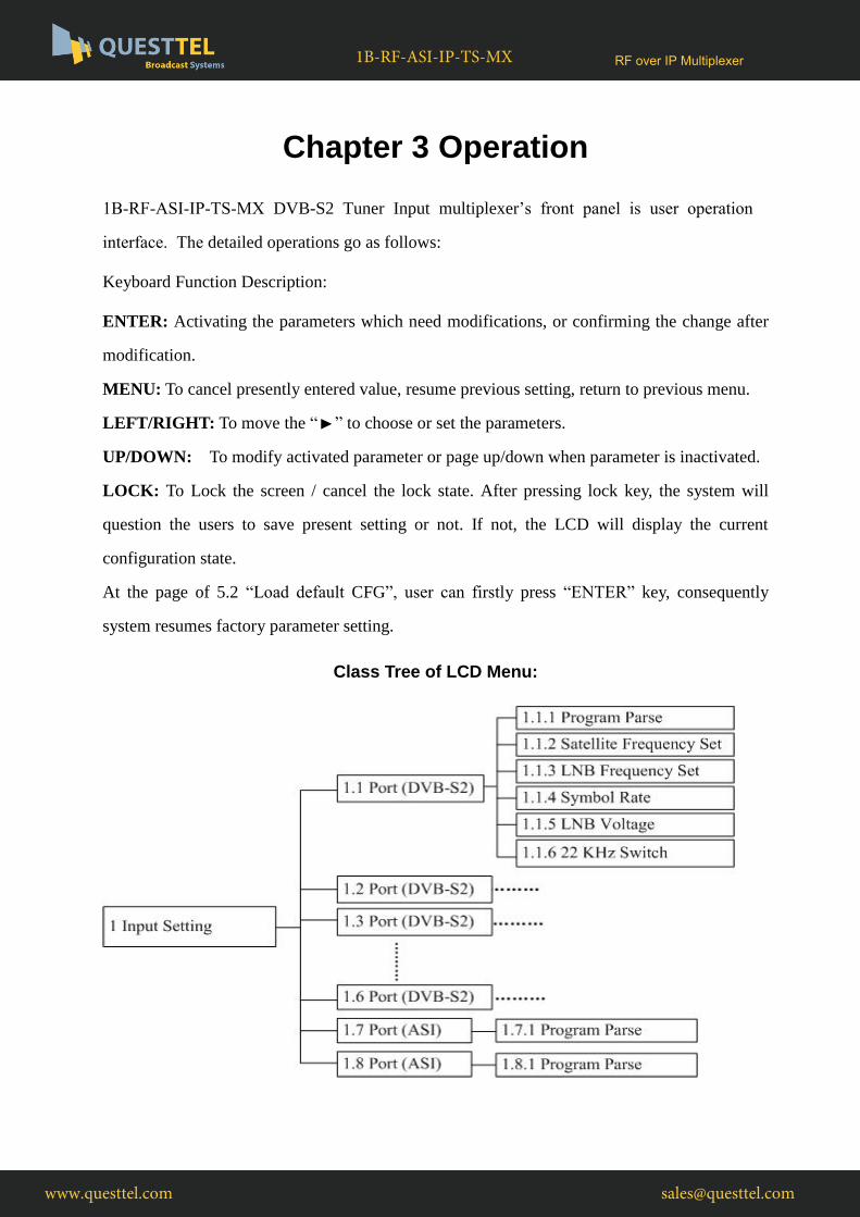
Class Tree of LCD Menu:
www.questtel.com [email protected]
RF over IP Multiplexer1B-RF-ASI-IP-TS-MX

3.1 Initializing
After switching on the multiplexer, the LCD will display the device name in the first row, while
the output program amount and real-time bit-rate of both output ports are displayed in the
second row.
www.questtel.com [email protected]
RF over IP Multiplexer1B-RF-ASI-IP-TS-MX

3.2 General setting
By pressing “LOCK” key to enter the main menu, user can enter the following pages:
The option with “►” is the current selection, users can press the ENTER key to enter the
specified submenu to modify the device parameter.
3.2.1 Input Setting
User can press “ENTER” key to enter into the menu of Input Setting when this menu is marked
with . It shows as bellow:
The two-page menu from 1.1 to 1.8 represent the 6 tuner input ports and 2 ASI input ports of
this multiplexer. User can multiplex the input programs from any port to output either output
port A or port B, or output ports both A and B.
1. Input Setting 2. Output Setting
3. Network Setting 4. Saving configuration
5. Loading configuration 6. Version
7. Language
Tuner Mux
1: P 02 Out 000.000M 2: P 01 Out 000.000M
Output Port
Serial Number
Program Amount
Real-time Bit-rate
1.1 Port (DVB-S2) 1.2 Port (DVB-S2)
1.3 Port (DVB-S2) 1.4 Port (DVB-S2)
1.5 Port (DVB-S2) 1.6 Port (DVB-S2)
1.7 Port (ASI) 1.8 Port (ASI)
www.questtel.com [email protected]
RF over IP Multiplexer1B-RF-ASI-IP-TS-MX

3.2.1.1 Tuner Input (DVB)
Here we take the 1.1 Port (DVB) signal input as an example:
User pressing the “ENTER” key, the device will analyze the input TS or signal and then display
the program list at the submenu 1.1.1-1.1.6.
By pressing the “ENTER” key, user can enter the submenu of 1.1.1 Program Parse.
At the submenu 1.1.1, the first row displays the port number and the program amount. For
example, Port 1 means the signal comes from port 1 and the “Prog 4” means the quantity of the
program is 4.
Also user can check and set the satellite frequency, LNB frequency and symbol rate at the
corresponding submenus “1.1.2”, “1.1.3” “1.1.4”.
1) To move the underline through LEFT/RIGHT keys.
2) To modify the value of underlined character through UP/DOWN keys
1.1.5 LNB voltage 1.1.6 22 KHz Switch
1.1.1 Prog Parse Port 1 Prog 4
1.1.1 Prog Parse 1.1.2 Sat Freq Set
1.1.3 LNB Freq Set 1.1.4 Symbol Rate
1.1.2 Sat Freq Set
03840 MHz
1.1.3 LNB Freq Set
05150 MHz
1.1.4 Symbol Rate
27.500 Msps
www.questtel.com [email protected]
RF over IP Multiplexer1B-RF-ASI-IP-TS-MX

At the submenu 1.1.5, user can select the LNB voltage from the 3 options shown below by
moving LEFT/RIGHT keys and pressing ENTER to confirm.
At the submenu 1.1.6, user can decide whether to enable or disable the 22 KHz Switch.
P.S.: The descriptions of 1.2-1.6 Port (DVB) signal input are the same.
3.2.1.2 ASI Input
Here we take port 1.1.7 port (ASI IN) as an example:
At the submenu 1.7.1, the first row displays the port number and the program amount. For
example, Port 7 means the TS stream comes from port 7 and the “Prog 3” means the quantity of
the programs is 3.
P.S.: The descriptions of 1.8 Port (ASI) signal input are the same.
3.2.2 Output Setting
User can press “ENTER” key to enter into the menu of Output Setting.
3.2.2.1 Output 1
User can set the parameters of ASI and IP output in this submenu.
1.1.6 22 KHZ Switch
*OFF ON
1.7.1 Prog Parse Port7 Prog 3
2.1 Output 1 2.2 Output 2
2.3 UTC Time Config
1.1.5 LNB voltage
V (13V) *H (18V) OFF (0V)
www.questtel.com [email protected]
RF over IP Multiplexer1B-RF-ASI-IP-TS-MX

Output Stream
At this menu, user can set the total output bit-rate which includes the effective bit-rate of
multiplexed programs from all input ports and the bit-rate of stuffed null pockets.
Trans Stream ID
This is a 16-bit field which serves as a label for identification of the out TS. The value ranges
from 0 to 0xFFFF.
Out IP Enable
At this submenu, user can decide whether to enable or disable IP output of port A.
Out Address
User can check and set the IP output address at this submenu.
Output Port
2.1.1 Output Strea 2.1.2 Trans Stream
2.1.3 Out IP Enable 2.1.4 Out Address
2.1.5 Out Port
2.1.3 Out IP Enable
Yes *No
2.1.4 Out Address
224.002.002.003
2.1.1 Output Stream
054.000 Mbps
2.1.2 Trans Stream ID
00000
www.questtel.com [email protected]
RF over IP Multiplexer1B-RF-ASI-IP-TS-MX

The description and settings of 2.2 port 2 are the same as the 2.1 port 1.
P.S.: The description of 2.2 Output 2 is the same with 2.1.
3.2.2.2 UTC Time Configuration
UTC refers to Universal Time Coordinated. User can enter this menu to set the time as needed
and it will then generate the DTD table and show in the user’s STB.
3.2.3 Network Setting
User can press “ENTER” key to enter into below menus of the Network Setting and modify the
parameters under its corresponding submenu in the same way explained above.
10/100M IP Setting
The 10/100Mbps Network port is for NMS controlling only. User can set the device’s NMS
networking parameters in the series of submenus.
2.1.5 Output Port
01001
3.1 IP Address
192.168.002.136
3.2 Subnet Mask
255.255.255.000
3.3 Gateway
192.168.000.001
UTC Time Configuration
2012-01-29 15:45:03
www.questtel.com [email protected]
RF over IP Multiplexer1B-RF-ASI-IP-TS-MX

Note: The MAC address is according to the factory setting, and it’s unique.
This port can be used as communication port for NMS management.
3.2.4 Saving Configuration.
User can choose No or Yes to save the current configuration parameters at this menu.
3.2.5 Loading Config.
User can restore the device into the last saved configuration by choosing the menu 5.1 “Load
Saved CFG”, and also user can restore the device into factory configuration by choosing the
menu 5.2 “Load Default CFG”.
3.2.6 Version
3.4 Console Address
224.002.002.002
3.5 MAC Address
ffffffffffff
3.6 NMS Port
02007
4.1 Saving Configuration
Yes * No
Saving, please wait:
>>>>>>>>>>>>>>>
5.1 Load Saved CFG 5.2 Load Default CFG
Loading, please wait:
>>>>>>>>>>>>>>>
www.questtel.com [email protected]
RF over IP Multiplexer1B-RF-ASI-IP-TS-MX

User can check the device’s hardware version and software version at this submenu:
HW1.7 SW 01.05
www.questtel.com [email protected]
RF over IP Multiplexer1B-RF-ASI-IP-TS-MX

Chapter 4 Troubleshooting
Preventive Measures
Installing the device at the place in which environment temperature is between 0 to 45 °C
Making sure good ventilation for the heat-sink on the rear panel and other heat-sink bores
if necessary
Checking the input AC within the power supply working range and the connection is
correct before switching on device
Checking the RF output level varies within tolerant range if it is necessary
Checking all signal cables have been properly connected
Frequently switching on/off device is prohibited; the interval between every switching
on/off must be greater than 10 seconds.
Conditions need to unplug the power cord
Power cord or socket damaged.
Any liquid flowed into device.
Any stuff causes circuit short
Device in damp environment
Device was suffered from physical damage
Longtime idle.
After switching on and restoring to factory setting, device still cannot work properly.
Maintenance needed
www.questtel.com [email protected]
RF over IP Multiplexer1B-RF-ASI-IP-TS-MX