Embed Size (px)
Citation preview
010407-037-Attachment-2
1 2 Document Type: Technical Report 3 TITLE: Location Acquisition and Location Parameter Conveyance for Internet Access 4 Networks in Support of Emergency Services 5 DOCUMENT NUMBER: ATIS-XXXXXX. 6 SOURCE: Emergency Services Interconnection Forum 7 CONTACT: Anand Akundi, Telcordia Technologies, (732) 699-6031; Christian Militeau, 8 Intrado Inc., (720) 864-5245 9 10
1.1 Abstract 11 This document describes the specific areas of location acquisition and location parameter 12 conveyance in Internet access networks. It concerns itself with both the architectures and 13 protocols for supporting these functions. In brief, this is about the manner in which IP 14 devices such as VoIP clients request location information from a LIS function in any access 15 network – location acquisition. It is also about the manner in which the LIS function obtains 16 the value of parameters from access networks pertinent to the IP address of the requesting 17 IP device in order that it can actually calculate the device’s location. 18 The LIS function is identified as an essential component of the NENA-defined i2 architecture 19 for VoIP emergency services and continues to be required in the i3 architecture currently 20 under definition. This document starts with the LIS requirements specified by NENA in terms 21 of those architectures. It examines candidate protocols for location acquisition – HELD, 22 DHCP, LLDP-MED – and provides a gap analysis. 23 The concepts of location parameter conveyance are described and a specific architecture – 24 the LIS-ALE architecture – is elaborated on. A flexible LIS-ALE protocol is described – FLAP 25 – and examples are provided of its application in some common forms of broadband access 26 networks. 27 This technical report is intended to be used as input to further decision-making processes 28 leading to any necessary policy and/or American National Standards formulation. It will be 29 used as a vehicle for communicating concepts in liaisons with other relevant SDOs. 30 31
32
1.2 Notice 33 This is a draft document and thus, is dynamic in nature. It does not reflect a consensus of ESIF members and it may be changed or modified. Neither 34 ATIS nor ESIF makes any representation or warranty, express of implied, with respect to the sufficiency, accuracy or utility of the information or 35 opinion contained or reflected in the material utilized. ATIS and ESIF further expressly advise that any use of or reliance upon the material in 36 question is at your risk and neither ATIS nor ESIF shall be liable for any damage or injury, of whatever nature, incurred by any person arising out of 37 any utilization of the material. It is possible that this material will at some future date be included in a copyrighted work by ATIS. 38 39

ATIS-XXXXXXX
2
1 Document ATIS-XXXXXX. 2
Prepared by 3 Emergency Services Interconnection Forum 4
Working Group 5 Next Generation Emergency Services Subcommittee (NGES) Issue 50 6
7
1 ATIS-XXXXXX 2
3 4
5 Location Acquisition and Location Parameter Conveyance for Internet Access 6
7 Abstract 8
This ATIS Technical Report is not intended to be seen as an American National Standard. 9 Rather it is intended to be used as input to further decision-making processes leading to 10 any necessary policy and/or American National Standards formulation. It will be used as a 11 vehicle for communicating concepts in liaisons with other relevant SDOs. 12 This document describes the specific areas of location acquisition and location parameter 13 conveyance in IP access networks. It concerns itself with both the architectures and 14 protocols for supporting these functions. In brief, this is about the manner in which IP 15 devices such as VoIP clients request location information from a LIS function in any 16 access network – location acquisition. It is also about the manner in which the LIS function 17 obtains the value of parameters from access networks pertinent to the IP address of the 18 requesting IP device in order that it can actually calculate the device’s location. 19 The LIS function is identified as an essential component of the NENA-defined i2 20 architecture for VoIP emergency services and continues to be required in the i3 21 architecture currently under definition. This document starts with the LIS requirements 22 specified by NENA in terms of those architectures. It examines candidate protocols for 23 location acquisition –DHCP, LLDP-MED, HELD – and provides a gap analysis. 24 The concepts of location parameter conveyance are described and a specific architecture 25 – the LIS-ALE architecture – is elaborated on. A flexible LIS-ALE protocol is described – 26 FLAP – and examples are provided of its application in some common forms of broadband 27 access networks. 28 29
30 31
1.3 Foreword 1 The rapid rise of Voice over IP telephony services was anticipated by the National 2 Emergency Number Association (NENA). In 2003, it established working groups to define 3 a “migratory” architecture (i2) and an “end game” architecture (i3) to provide the ability to 4 reliably deliver and process emergency calls originated by Internet-based VoIP telephony 5 users. Both the i2 and i3 architectures depend on the ability to determine and 6 communicate the location of the caller so that a) the call can be routed to the correct 7 PSAP and b) the location can be delivered to the PSAP operator for dispatch and other 8 procedural purposes. The network element identified to perform this function is associated 9 with the access network used by the VoIP caller and is called the Location Information 10 Server (LIS). NENA i2 documents define the LIS related requirements, and the form of 11 location information provided, however they do not provide the detailed protocol 12 specifications associated with LIS functionality. 13 In practice, the role of the LIS can be split into at least two key functions: 14
• Location acquisition – the protocol and associated semantics by which IP devices 15 and applications request location information from the LIS. 16
• Location measurement and determination – the function and any associated 17 protocols associated with obtaining and evaluating network and other parameters 18 that are associated with the device in order to calculate the device’s location. 19 Getting these relevant parameters delivered from the network may be termed 20 “location parameter conveyance”. 21
In order to provide global consistency for devices such that location information can be 22 retrieved in the same way regardless of the kind of network they are currently attached to, 23 it is important that Location Acquisition is done in the same way independent of the 24 technology underpinning that access network. On the other hand, the parameters 25 important to location determination, the manner in which location is calculated, and the 26 form of location (e.g. civic and/or geodetic) will vary significantly depending on the nature 27 of the access technology. That is, the parameters and algorithms associated with 28 determining location in an ADSL network will be significantly different than doing the same 29 in a WiMAX network. By definition, then, location acquisition is ideally network technology 30 independent while location parameter conveyance and determination is network 31 technology dependent. 32
1.4 Revision History 33
Revision Date Remarks .01 July 5 2006 Version .01 skeleton document for group discussion .02 July 19 2006 Added NENA acquisition protocol requirements matrix 0.3 Sept 11 2006 Added example for DSL 0.4 21 Sept 2006 Added examples for cable, 3G Cellular 0.5 22 Sept 2006 Added examples for wired Ethernet 018-R3 October 3, 2006 Added sections 4 – 7 018-R4 October 11, 2006 Continued editing process throughout the document, added Definitions
and Acronyms sections 018-R5 October 25, 2006 Completed sections on WiMAX and WiFi. Address action points

ATIS-XXXXXXX
2
arising from detailed review conducted at ESIF-19 meeting. Added RELO to the location acquisition protocol comparison matrix.
018-R6 November 8, 2006 Further updates to diagrams and text following review. Added LREP-SIP to the location acquisition protocol comparison matrix.
018-R6.1 November 8,2 006 Tweaks to existing text throughout the file, all of which are subject to review prior to being “accepted”.
018-R7 November 29, 2006 More review comments incorporated. Added LCP as yet another candidate acquisition protocol.
050-002 December 6, 2006 New baseline document created from all prior work, most recently from 018-R7
050-002-R1 December 7, 2006 Deleted Section 3 (Definitions) by group consensus, which resulted in all section beyond #3 being renumbered, i.e. 4 became 3 etc. Also added some Comments to remind us of intended Action Items, added entries to the Abbreviations, Acronyms, and Symbols table, and alphabetized it, and a few other editorial corrections.
050-002-R2 December 21, 2006 Liaison distribution version
ATIS-XXXXXXX
3
Table of Contents 1 1.1 Abstract ............................................................................................................................................ 1 2 1.2 Notice ............................................................................................................................................... 1 3 1.3 Foreword .......................................................................................................................................... 1 4 1.4 Revision History ............................................................................................................................... 1 5
2 Introduction/Executive Summary ........................................................................................................... 5 6 2.1 Target Audience............................................................................................................................... 5 7
3 Abbreviations, Acronyms, and Symbols ................................................................................................ 6 8 4 NENA i2 and i2 Architecture .................................................................................................................. 8 9
4.1 Summary of LIS Functions in the NENA Architecture ..................................................................... 9 10 4.2 LIS Requirements Prescribed By NENA.......................................................................................... 9 11 4.3 The NENA i2 architecture and global interoperability ....................................................................11 12
5 Location Determination in Broadband Access Networks.....................................................................12 13 5.1 Example ADSL Network.................................................................................................................12 14
5.1.1 DSL Connectivity Over L2TP ................................................................................................12 15 5.2 Example Cable Network.................................................................................................................15 16 5.3 Example WiMAX Network..............................................................................................................17 17 5.4 Examples of 3G Cellular Networks ................................................................................................18 18
5.4.1 3G packet data variants deployed in the United States ........................................................19 19 5.5 Example Enterprise (Ethernet Switch/WiFi) Network ....................................................................21 20
5.5.1 Wired Ethernet.......................................................................................................................21 21 5.5.2 Wireless Ethernet ..................................................................................................................24 22
6 LIS Operational Considerations...........................................................................................................25 23 6.1 Types of LIS and LIS Operators ....................................................................................................26 24
6.1.1 Access Infrastructure Provider Network................................................................................27 25 6.1.2 Internet Service Provider.......................................................................................................27 26 6.1.3 Geo-distributed LAN..............................................................................................................27 27 6.1.4 Geo-point LAN.......................................................................................................................28 28 6.1.5 Summary ...............................................................................................................................28 29
6.2 Certificate Security and Management............................................................................................29 30 6.3 OSS Integration Considerations ....................................................................................................30 31
7 Location Acquisition Protocols.............................................................................................................30 32 7.1 Protocol Descriptions .....................................................................................................................30 33
7.1.1 Dynamic Host Configuration Protocol (DHCP) RFC3825 .....................................................30 34 7.1.2 Link Layer Discovery Protocol for Media Endpoint Devices (LLDP-MED)............................31 35 7.1.3 HTTP Enabled Location Delivery (HELD) .............................................................................31 36 7.1.4 Retrieving End-System LOcation information (RELO)..........................................................31 37
ATIS-XXXXXXX
4
7.1.5 A Location Reference Event Package for the Session Initiated Protocol (LREP-SIP) .........31 1 7.1.6 Location Configuration Protocol (LCP)..................................................................................31 2
7.2 Location Protocol Gap Analysis Against NENA i2 Requirements .................................................32 3 7.3 Findings..........................................................................................................................................34 4 7.4 HELD Status ..................................................................................................................................35 5
8 Location Parameter Conveyance ........................................................................................................35 6 8.1 LIS-ALE Architecture......................................................................................................................36 7 8.2 FLAP Protocol ................................................................................................................................37 8
8.2.1 FLAP Description...................................................................................................................37 9 8.2.2 Supported FLAP Messages ..................................................................................................38 10
8.3 FLAP Examples .............................................................................................................................40 11 8.4 Considerations of FLAP versus “Technology Specific Solutions”..................................................42 12 8.5 Status of FLAP...............................................................................................................................43 13
9 References...........................................................................................................................................43 14 15 16
Table of Figures 17 18
Figure 4-1 NENA i2 architecture ................................................................................................................... 8 19 Figure 5-1 DSL Connectivity Using L2TP ...................................................................................................13 20 Figure 5-2 DSL L2TP Network Connectivity Message Flows.....................................................................14 21 Figure 5-3 LIS In A Cable Network .............................................................................................................16 22 Figure 5-4 WiMAX network .........................................................................................................................18 23 Figure 5-5 Data and Voice Separation In A Cellular Network.....................................................................19 24 Figure 5-6 GSM-GPRS Network.................................................................................................................20 25 Figure 5-7 LIS in GPRS Network ................................................................................................................21 26 Figure 5-8 Cascaded Switch Network with DHCP Relay............................................................................22 27 Figure 5-9 SNMP Bridge MIB ALE..............................................................................................................23 28 Figure 5-10 ALES Accessing DHCP Lease Information.............................................................................24 29 Figure 6-1 LIS Types and associated network types..................................................................................29 30 Figure 8-1 The General LIS-ALE Architecture ............................................................................................36 31 Figure 8-2 The ALE-to-LIS Notification Message Flow...............................................................................38 32 Figure 8-3 The LIS-to-ALE Resynchronization Message Flow..................................................................39 33 Figure 8-4 The LIS-to-ALE Access Query Message Flow ..........................................................................40 34
35
ATIS-XXXXXXX
5
1
2 Introduction/Executive Summary 2
The NENA VoIP migratory working group defined the i2 network architecture 3 designed to support emergency service calls originating from VoIP services on the 4 Internet. The architecture identifies a network element called the Location 5 Information Server (LIS) that provides location data used for call routing and for 6 display at the PSAP operator terminal. 7 The i2 specification did not detail the protocol to be used by the LIS for providing 8 location information to the VoIP device or proxy nor the manner in which location 9 should be determined for different Internet access technology types. A separate 10 NENA document [18] defined the requirements for the LIS. NENA requested 11 ATIS/ESIF to provide recommendations for the protocol and implementation 12 specifics of the LIS function for the broadband access and emergency services 13 industry. 14 This document divides the subject into two areas. The first is “Location Acquisition” 15 which describes the manner in which LIS clients interact with the server to obtain 16 location. Candidate location acquisition protocols (DHCP, LLDP-MED, HELD, and 17 RELO) are compared against the NENA defined requirements. The second area is 18 “Location Determination” which is the manner in which a LIS determines the 19 location of a device in specific access network types. A variety of access 20 technologies are examined and a generic architecture based on access location 21 entities (ALE) providing network parameters to the LIS is described. A protocol 22 called the Flexible LIS-ALE Protocol (FLAP) is described which supports this 23 architecture. 24 The results of the location acquisition protocol comparison and the description of 25 the LIS-ALE architecture and FLAP protocols are provided as a basis for 26 discussion and decision-making. Input from a range of SDOs in response to this 27 document is to be sought. 28
2.1 Target Audience 29 This document is directed to the members of the NGES subcommittee dealing with Issue 30 50 and tasked with progressing recommendations around policy and standard formulation. 31 It provides a technical overview of the scope of issue and specific terms of reference 32 currently viewed as significant to progress. It is also directed towards those members of 33 third party SDOs who may be in receipt of liaisons from this subcommittee requesting 34 input in the form of opinion, information, or decisions pertinent to the subcommittee’s 35 ability to progress the work associated with the issue. 36
ATIS-XXXXXXX
6
3 Abbreviations, Acronyms, and Symbols 1
Term Brief Definition
ALE Access Location Entity
ATM : Asynchronous Transfer Mode
BEEP Blocks Extensible Exchange Protocol (RFC3080, RFC3081)
BRAS : Broadband Regional Access Server
BSSLAP Base Station System Location Assistance Protocol
CMTS : Cable Modem Termination System
DHCP Dynamic Host Configuration Protocol (44)
DSL : Digital Subscriber Line (44)
DSLAM : DSL Access Module
FLAP Flexible LIS-ALE Protocol
GGSN : Gateway GPRS Support Node
GMLC Gateway Mobile Location Center
GPRS : General Packet Radio Service
HELD HTTP Enabled Location Delivery (43)
ISP : Internet Service Provider
L2TP : Layer 2 Tunneling Protocol
LIS Location Information Server
LMU : Location Measurement Unit
MAC : Media Access Control
NAS : Network Access Server
PVC : Permanent Virtual Circuit
RANP : Regional Access Network Provider
ATIS-XXXXXXX
7
Term Brief Definition
RBP : Regional Broadband Provider
SGSN : Serving GPRS Support Node
SLP SUPL Location Platform
SMLC Serving Mobile Location Center
SNMP : Simple Network Management Protocol
SUPL Secure User Plane Location
VESA : Valid Emergency Service Authority
VPC : VoIP Positioning Center
1 2
ATIS-XXXXXXX
8
1
4 NENA i2 and i2 Architecture 2
Overview description 3 The NENA i2 initiative [01] was proposed with the intent of addressing the immediate need 4 of providing standard emergency services support to next generation Residential 5 Broadband VoIP phone users. A strong requirement of i2 from the onset was to make little 6 or no change to the existing emergency infrastructure, in particular any solution was to 7 impose no change to PSAPs. The data sets associated with location of an IP device, when 8 investigated further were found to be remarkably similar to location parameters associated 9 in wireless cellular networks. The resulting architecture for i2 therefore closely resembles 10 the architecture created to address the wireless Phase II emergency requirements 11 12
13 Figure 4-1 NENA i2 architecture 14
The NENA i2 architecture (see Figure 4-1) identified 5 new network elements, 9 new 15 interfaces, and made minor changes to the E2+ to support VoIP class of service indicators 16 between the new VoIP Positioning Center (VPC) and the existing ALI infrastructure. While 17 the detailed functions of each of the new 5 network elements is defined in the i2 18 specification, not all of the interfaces between nodes are specified. Specifically, the V0 and 19 V1 interfaces were deemed out of scope for i2. 20 There are three key components of the i2 architecture that the VoIP service interacts with 21 and which would benefit from global adoption: 22
ATIS-XXXXXXX
9
• The manner in which the VoIP device obtains and provides location information to 1 the call server (the LIS) 2
• The manner in which the VoIP call server proffers location information in exchange 3 for routing information and for delivery to the emergency services network (the 4 VPC) 5
• The manner in which the VoIP call server routes the call out of the Internet and into 6 the emergency network of the destination jurisdiction (the ESGW) 7
The V2 interface to the VPC is well described and specified in the i2 architecture 8 document. Similarly the function of the ESGW is well understood. By the same token, 9 these elements are the ones which have the most scope for regional variance. In the US, 10 the VPC is queried by the PSAP via the E2 interface. Other jurisdictions may use other 11 protocols such as MLP. In the US, the ESGW provides dedicated trunks to selective 12 routers. In other jurisdictions, the ESGW may route the emergency call onto the PSTN. In 13 addition, the VPC and ESGW are migratory solution constructs. They don’t necessarily 14 have a long term role into a future where emergency calling occurs on IP end-to-end 15 between VoIP devices and VoIP enabled emergency call centers. 16 In contrast to the VPC and ESGW functions, the LIS interfaces (V0 and V1) have the least 17 level of detail in the i2 specification. The V1 interface is recognized to be VoIP-protocol 18 specific so the only requirement cited by i2 is the ability of that interface to convey location 19 in the form of a PIDF-LO or as a reference. The LIS function can and should be consistent 20 on a cross-national jurisdiction basis. This means a device can acquire location 21 information in the same way regardless of the network to which it is attached. The LIS will 22 continue to be relevant in the long term as the need to determine and acquire device 23 location exists regardless of the call being delivered through a legacy infrastructure or on 24 end-to-end IP. 25 This document focuses on the LIS functionality. It documents considerations and the 26 recommendations of the ESIF NGES WG with respect to the implementation of LIS 27 functionality. 28
4.1 Summary of LIS Functions in the NENA Architecture 29 While the i2 architecture did not elaborate on the form of the V0 interface protocol(s) or the 30 manner in which the LIS is expected to determine device location, the i2 working group did 31 provide supporting technical documents describing the requirements for the V0 interface 32 and for the LIS function [18]. 33 The requirements for the LIS were divided into three areas 34
• Location determination and acquisition (DA) 35 • Location representation (Rep) 36 • Location security and dependability (LocSec) 37
The following section lists these requirements. 38
4.2 LIS Requirements Prescribed By NENA 39 The following requirements come from the NENA Requirements for the location 40 information to support emergency services [18]. 41
ATIS-XXXXXXX
10
DA1– The access network shall provide a mechanism for determination and acquisition of 1 location information, and support queries for location. 2 DA2 – The location estimate used shall be that associated with the physically (wire, fiber, 3 air) connected network. 4 DA3 – Location may be requested at any time. Location information must be associated 5 with the device at the time the location is requested. 6 DA4 – Location acquisition should be provided by a consistent method across all network 7 configurations. 8 DA5 – Location determination and acquisition mechanisms should be applicable to 9 emergency calling; they may also be applicable to a wide range of value-added location-10 based services. 11 DA6 – Location determination and acquisition techniques shall support both NENA i2 and 12 i3 network architectures. 13 DA7 – When measurement-based location determination mechanisms fail, the most 14 accurate location information available should be provided. Examples include: For mobile, 15 the Wireless Service Provider might provide tower/Access Point location, last known fix, 16 etc. For wireline, a LIS might provide a civic location that defines the serving area of an 17 access point, e.g., the State of Texas. 18 DA8 – Location determination and acquisition must have minimal impact on call setup 19 time in the event that location is not known ahead of time. 20 DA9 – Where a device is not location aware, the network should have the ability to 21 assert a location estimate on behalf of the device. 22 DA10 – Location acquisition methods should not require modification of 23 hardware/firmware in home-routers/modems. 24 DA11 – A location determination method must exist that does not require network 25 hardware replacement in the core network. 26 DA12 – The location acquisition protocol shall allow the requesting device to specify a 27 response time requirement to the LIS when requesting location information. The response 28 time is expressed as the maximum time that the requesting node is prepared to wait for 29 location information. The LIS is required to provide the most accurate location fix it can 30 within the specified response time. 31 32 Rep1– Location information may be provided by-value or by-reference; the form is subject 33 to the nature of the request. 34 Rep2 – Location determination and acquisition mechanisms must support all location 35 information fields defined within a PIDF-LO. 36 Rep3 – Location acquisition mechanisms must allow for easy backwards compatibility as 37 the representation of location information evolves. 38 Rep4 – All representations of location shall include the ability to carry altitude and/or floor 39 designation. This requirement does not imply altitude and/or floor designation is always 40 used or supplied. 41
ATIS-XXXXXXX
11
LocSec1– Location information shall only be provided to authenticated and authorized 1 network devices. The degree of authentication and authorization required may vary 2 depending on the network. 3 LocSec2 – Location determination and acquisition methods should preserve privacy of 4 location information, subject to local laws and regulations applicable to the endpoint’s 5 geographic location. 6 LocSec 3 – The location or location estimate of a caller should be dependable. 7 LocSec4 – The location acquisition protocol must support authentication of the Location 8 Information Server, integrity protection of the Location Information, and protection against 9 replay. 10 LocSec5 – The location source shall be identified and should be authenticated. This 11 includes manually entered locations. 12 LocSec6 – Where a location is acquired and cached prior to an emergency call, it 13 SHOULD be refreshed at regular intervals to ensure that it is as current as possible in the 14 event location information cannot be obtained in real time. 15 LocSec 7 – Where location by-reference is used, the appropriate privacy policies MUST 16 be implemented and enforced by the LIS operator. 17 18
4.3 The NENA i2 architecture and global interoperability 19 The i2 architecture has relevance beyond the North American emergency services 20 infrastructure. In traditional wireline and cellular networks, where the voice service provider 21 and the access provider are the same entity there has been some latitude from one 22 national jurisdiction to another in terms of how emergency calls are processed. In 23 particular, the local network operator had full responsibility for emergency call processing 24 in these traditional networks. As long as the user’s device (e.g. GSM phone) was 25 compatible with the dialing of emergency services, the rest of the process could be 26 jurisdiction-specific. VoIP breaks this coupling between access and voice service provision 27 and, in the case of emergency calling, it introduces cross-jurisdictional considerations that 28 have not previously existed. For example, a caller may roam from one national jurisdiction 29 to another but their VoIP service provider does not change. The same VoIP call server will 30 be engaged in the processing of an emergency call regardless of the point of origination of 31 the call. This requires the call server to successfully inter-operate with the emergency 32 calling infrastructure of an arbitrary number of national jurisdictions. Subscribers don’t 33 even need to be roaming for this to occur since the subscribers to a VoIP service may be 34 foreign nationals, and foreign-based, to begin with. Being able to support a global 35 subscriber base also creates the requirement for a VoIP provider to inter-operate with the 36 emergency infrastructure of multiple national jurisdictions. 37 Global inter-operability could be enhanced if the i2 architecture were widely adopted. The 38 two key functions of emergency call routing and the delivery of location information that 39 the i2 architecture provides are actually common to emergency services world-wide. 40 Rather than requiring a call server implementation to adapt to an arbitrary number of 41 systems, protocols, and interfaces, there is a major benefit if all jurisdictions adopt the 42 same approach. 43 44
ATIS-XXXXXXX
12
5 Location Determination in Broadband Access Networks 1
This section describes a range of access technologies and provides examples of how 2 location determination is possible, and the key parameters that need to be captured in 3 order to permit location determination.. The examples provided are illustrative and not 4 comprehensive nor definitive. The descriptions of ADSL, cable, and 3G technologies are 5 accurate in terms of representing actual deployment topologies and signaling scenarios 6 though there is scope for variation in detail in the real world. WiMAX standards are still 7 under definition by the IEEE and references to the types of network parameters that 8 contribute to location determination and the signaling scenarios by which those 9 parameters may be extracted from the network are more speculative. 10 Note that the term “access location entity” (ALE) is used in various parts of the following 11 descriptions. This term is fully defined in Section 8 and the reader is referred to that 12 section for background on this function. It is included so that the examples are more 13 readily understood in the context of a general location parameter architecture. For the 14 purposes of this section, the term “ALE” is used to identify a logical function and does not 15 refer to a particular product, technology, or standard. 16
5.1 Example ADSL Network 17 Asymmetric Digital Subscriber Line (ADSL) is the fastest growing technology used to 18 deliver residential broadband service in the world and boast about 140 million lines world-19 wide. Recommendations on DSL network configurations and protocols are provided by the 20 DSL forum and these are documented in Technical Reports (TRs) that are freely available 21 from the DSL forum website (www.dslforum.org). 22 The main DSL network configuration architectures are documented in TR-025 [15] and 23 TR-101 [16] and the example network described in this section will come from one of the 24 architectures described in TR-025. Other examples along with a high-level description of 25 DSL network entities are provided in the NENA location determination TID [20]. 26
5.1.1 DSL Connectivity Over L2TP 27 The basic DSL network configuration consists of a DSL modem at the customer's 28 premises that transports IP traffic from residence to the Internet. The DSL signals from the 29 modem are carried across copper wires to the local exchange where the DSL broadband 30 signals are extracted from the copper pair and sent to a DSL Access Module, or DSLAM. 31 The DSLAM has a dedicated circuit path to a central aggregator for each connected line. 32 In many cases this will be an ATM permanent virtual circuit (PVC), but in the case of an 33 Ethernet transport it may be a dedicated Ethernet VLAN identifier. 34 The central aggregator in this configuration is generally referred to as a broadband 35 regional access server, or BRAS. The BRAS terminates individual DSLAM data streams 36 and redirects them to the end-point/subscriber’s Internet Service Provider (ISP). The 37 BRAS determines which ISP to send any given data stream to, by using data configured 38 directly into the BRAS or by using a RADIUS server as shown in the example below. 39 The links between a BRAS and an ISP's network access server (NAS) vary from ISP to 40 ISP and BRAS to BRAS. The example network described in this section assumes that a 41 single layer 2 tunnel (L2T) exists between the BRAS and the ISP's NAS, and that each 42 end-point connected to the ISP has a session established inside the BRAS to NAS tunnel. 43
ATIS-XXXXXXX
13
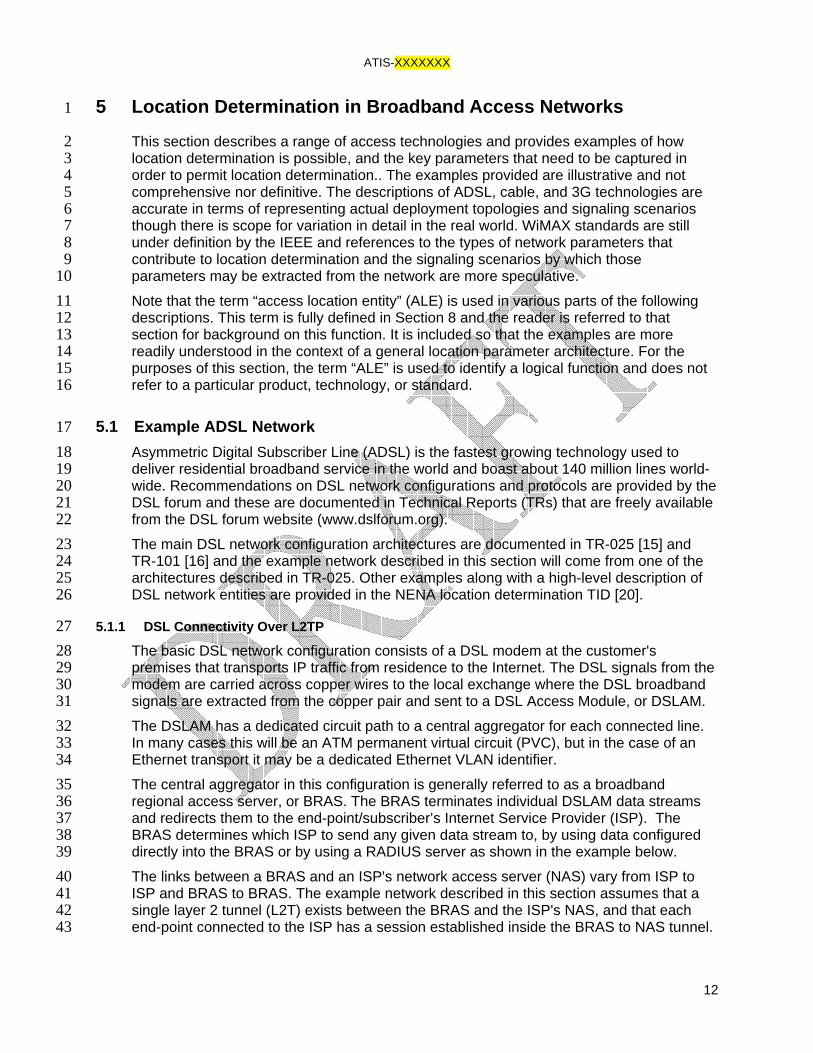
In this environment tunnel sessions are established dynamically when a connection is 1 made from the end-point to the ISP. The inclusion of a dynamic component between 2 the end-point and the ISP means that location cannot be resolved by only 3 provisioning circuit chains from the end-point to the ISP. The problem is resolved by 4 taking network parameters that provide a linkage between what the regional access 5 network provider (RANP) knows and what the ISP knows. In other words, the LIS 6 ultimately needs to correlate the IP address of the device with the residential address 7 associated with the DSL connection the device is using. The DSL connection may be 8 correlated with a number of access infrastructure circuit ID parameters finally culminating 9 in the identity of an L2TP tunnel; however, this does not resolve to the IP address of the 10 device. The ISP can provide additional information – specifically a correlation between the 11 L2TP tunnel identity and the IP address of the device – to add to the information available 12 to the access infrastructure provider. Together this information provides a linkage between 13 the IP address of the end-point, the tunnel and session between the NAS and BRAS, and 14 ultimately the circuit information from the BRAS to the DSLAM and the copper pair running 15 to the premises where the end-point is housed. 16 A general network layout might look something similar to Figure 5-1 17
18 19
Figure 5-1 DSL Connectivity Using L2TP 20 In this configuration two LIS's are used, one at the ISP that provides a linkage between IP 21 address and tunnel-session information, and second LIS in the regional access network 22 that provides the mapping from tunnel-session information into a provisioned circuit chain 23 that ultimately yields the location of the end-point. The message flows used in this 24 configuration are provided in Figure 5-2, along with a detailed description of each flow. 25
ATIS-XXXXXXX
14
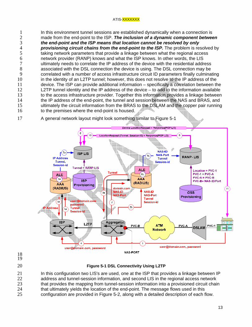
1 2
Figure 5-2 DSL L2TP Network Connectivity Message Flows 3 1. The user or end-point initiates a DSL connection, and passes network credential 4
information to the RANP BRAS. 5 2. The BRAS requests assistance from a RADIUS server to determine which ISP 6
NAS to send to the end-point data stream to. 7 3. a) The RADIUS server responds with a tunnel assignment. b) If there is no pre-8
existing tunnel, it is created and the RADIUS is provided the tunnel identity 9 4. A new session is created in the tunnel. 10 5. a) Authentication and authorization between the end-point and the ISP occurs. b) 11
An IP address is provided for the device. 12 6. (a&b) The RANP BRAS forwards the incoming BRAS port, the BRAS identity, 13
tunnel and tunnel session information to a RADIUS accounting server. This 14 information is also received by the RADIUS ALE and forwarded to the RANP LIS. 15
7. (a&b) At the same time, the ISP NAS forwards the incoming NAS port, NAS 16 identity tunnel, session and client IP address to a RADIUS accounting server. This 17 information is also received by the RADIUS ALE and forwarded to the ISP LIS. 18
8. The end-point makes a request for location to the ISP LIS. 19 9. The ISP LIS uses the end-point IP address to determine the tunnel and session 20
information. The ISP LIS uses the tunnel source information to determine which 21
ATIS-XXXXXXX
15
RANP LIS to query. The ISP LIS sends a location request to the RANP LIS which 1 includes the tunnel and session information. 2
10. The RANP LIS receives the location request with the tunnel and session 3 information and this as a key to determine the incoming BRAS and BRAS port 4 information. Once the BRAS and incoming port are identified, the location of the 5 end-point can be determined as the link between BRAS, BRAS port and location is 6 provisioned in the RANP LIS as shown in Figure 5-1. The RANP LIS constructs a 7 PIDF-LO and return this to the ISP LIS. 8
11. The ISP LIS returns the PIDF-LO to the end-point. 9
5.2 Example Cable Network 10 Cable networks are made up of multiple cable modems connected onto a single broadcast 11 cable. The bandwidth in the cable is divided into multiple frequency separated channels, 12 and each channel is comprised of a series of timeslots. Cable modems compete with each 13 other for channel and timeslot availability. A Cable Modem Termination System (CMTS) 14 residing at the head-end of the network is responsible for controlling transmission 15 characteristics such as channel and timeslot allocation for all cable modems in the 16 network. 17 The CMTS is connected to a router that switches network traffic to an ISP. A cable 18 network can therefore be thought of as a large distributed switched Ethernet network. This 19 type of environment makes it less easy to support multiple ISPs as is done in DSL 20 environments, though not impossible. Many cable network operators therefore either run 21 the ISP themselves or provide exclusive access to a small number of dedicated ISPs, 22 often one. 23 In most cases the CMTS and other switching devices can learn the MAC address of cable 24 modems connecting to the network. There is a need in cable networks however to be able 25 to associate a modem with a particular subscriber to ensure that the correct services are 26 made available to the end point. This association is generally performed through 27 registration and provisioning systems, which are often web-based, and provides the ISP 28 with a mechanism to link modem MAC address with end-point/modem location. 29 The tight coupling between cable network providers and ISP and the required modem 30 registration process place cable networks in a position where DHCP location acquisition 31 becomes a viable choice. Problems exist however with the inability of cable operators to 32 unilaterally upgrade subscriber modems or change hosts residing behind firewalls to be 33 compatible with this acquisition method. In addition the inability to provide location 34 dependability and compatibility with other network location solutions may cause cable 35 ISPs to consider an alternate location acquisition solution. 36 Location determination in a cable network relies on the tie between Ethernet MAC address 37 and physical location that is provisioned at the time the modem is registered to access the 38 network. To use an acquisition protocol may require a mapping between the IP address 39 and physical address, and this is accomplished in a cable network by establishing the 40 binding between the IP address and MAC address. Since the cable network is DHCP 41 based, a binding between MAC address and the IP address is available from the DHCP 42 server, and can be retrieved in a number of ways including using an ALE based around 43 the DHCP lease query protocol RFC4388 [21]. 44
ATIS-XXXXXXX
16
The network configuration to determine and provide location in a cable environment looks 1 similar to Figure 5-3. 2
The InternetLink
House
House
ISPNetwork
PC
Modem
DistributionHUB
CMTS
Router
Cable NetworkOperator
ISPRouter
OtherServices
DHCP Server
DNSInternetGateway
DHCP LeaseQuery ALE
TAP
House House
TAP
| MAC | LOC ||012345012345 | X Y Z ||FFAB01FFAB01 | A Z F |
LIS
IP -> MAC -> Location
FibreNode
1
2
7
3
4
5DHCP request Lease query
Location Request + Response(PIDF-LO)
3 Figure 5-3 LIS In A Cable Network 4
The message sequence associated with location determination and acquisition in the cable 5 network is shown in the following diagram. 6
Cable modemPC DHCP Server LISDHCP Lease Query ALE
DHCP Request
DHCP Resp (IP address)
Location request
FLAP request (IP address)DHCP Lease Query (IP address)
Lease Query Response (IP + MAC address) FLAP response (IP + MAC address)
Location response (PIDF-LO)
Location lookupMAC-> civic address
11
2
3
4
5
6
7
7
ATIS-XXXXXXX
17
1. The modem requests its IP address from the DHCP server. The DHCP server 1 provides the IP address and caches the association with the modem MAC address. 2 The modem was previously registered with the ISP, and the LIS is provisioned with 3 the MAC address and location of the modem. 4
2. The client on the PC discovers the LIS and makes a location request. 5 3. The LIS receives the location request and requests an IP address to MAC address 6
binding from the DHCP lease query ALE. 7 4. The DHCP lease query ALE receives the request and sends a lease query to the 8
DHCP server. 9 5. The DHCP server responds with the corresponding MAC address, and the ALE 10
passes this information up to the LIS. 11 6. The LIS uses the MAC address to look up the provisioned location. 12 7. The LIS constructs a PIDF-LO and returns this to the client running on the PC. 13
14
5.3 Example WiMAX Network 15 The label “WiMAX” applies to a range of wide area broadband wireless IP access 16 technologies – most specifically related to those defined by IEEE 802.16 and 802.20 17 specifications. It can be characterized as a public access carrier version of WiFi with metro 18 area coverage associated with a given wireless access point or base station. A WiMAX 19 “cell” can cover an area that is a number of kilometers across. WiMAX may be used to 20 provide fixed wireless access – where the technology is used to provide broadband 21 service to fixed locations such as subscriber residences. It can also be deployed to 22 provide mobile coverage such that users are provided broadband access from portable 23 devices in arbitrary locations and while on the move. 24 In the fixed wireless deployment model, location can be associated with the wireless 25 modem providing service for that fixed location. In this case WiMAX location service can 26 be implemented in the same way as described for cable broadband in section 5.2. The LIS 27 obtains the MAC address associated with the device from the DHCP server and consults 28 the subscriber data to find the corresponding residential, or other fixed location, address. 29 In the mobile deployment model, the WiMAX network location determination solutions 30 become more similar to traditional cellular location solutions. In order to determine the 31 location associated with the IP address of a particular device, the LIS will need to find the 32 network parameters that correspond to that device. As a starting point, it will want to 33 determine the base station which the device is currently attached to. This basic information 34 will allow the LIS to associate a geodetic area of uncertainty with the device which is 35 equivalent to the area of coverage of that WiMAX base station. This is the WiMAX 36 equivalent of a cell-based location in traditional cellular networks. 37 In order to further refine the location associated with the device, the LIS requires additional 38 network parameter values. These include radio parameters such as channel information, 39 signal time of arrival values, and signal strength measurements. Which WiMAX network 40 parameters are pertinent to the calculation of location is a subject for further study and 41 topic for consideration within the IEEE. 42 Obtaining the value of these parameters requires access parameter conveyance 43 associated with the radio interface. This may be accomplished by native ALE functionality 44
ATIS-XXXXXXX
18
in the WiMAX network controllers themselves or it may be provided through some overlay 1 facility such as location measurement units (LMUs) as shown in Figure 5-4. 2
LIS
BaseStation
NetworkController
ALE
LMU
ALE
Radio parameters – base station identity, channel information, timing, and signal strength values
Radio parameters – base station identity, channel information, timing, and signal strength values
WiMAX network
Internet
3 Figure 5-4 WiMAX network 4
A depiction of obtaining network parameters for the purpose of location determination from the 5 network and location measurement units (LMU) 6
5.4 Examples of 3G Cellular Networks 7 In recent years cellular telephone networks have evolved to support high-speed packet 8 data transmission that is used for Internet access. The type of traffic exchanged between 9 the network and handset is separated out at the base station controller, with telephony 10 traffic going to the MSC and packet data going to a packet serving node. This is shown in 11 Figure 5-5. 12
ATIS-XXXXXXX
19
1 Figure 5-5 Data and Voice Separation In A Cellular Network 2
5.4.1 3G packet data variants deployed in the United States 3 The two main 3G packet data variants deployed in the United States are: 4
• UMTS, based on 3GPP GPRS standards 5 • 1xEVDO, based on 3GPP2 standards. 6
In this section we shall examine a GPRS solution, but the principles are also applicable to 7 1xEVDO. A full description of these networks is provided in [22]. 8 GPRS introduces a number of new nodes to a GSM/UMTS network, the two main ones 9 being the Serving GPRS Support Node (SGSN) and the Gateway GPRS Support Node 10 (GGSN) – see Figure 5-6. 11 The SGSN is analogous to a VLR/MSC In the cellular voice world. It is responsible for 12 device authentication, authorization, registration and mobility management functions. The 13 SGSN is also responsible for all protocol conversions that need to occur between the 14 mobile air interface and the protocols used over the carrier's core network. All data sent by 15 or to the mobile device in a GPRS network travels through the SGSN. 16
ATIS-XXXXXXX
20
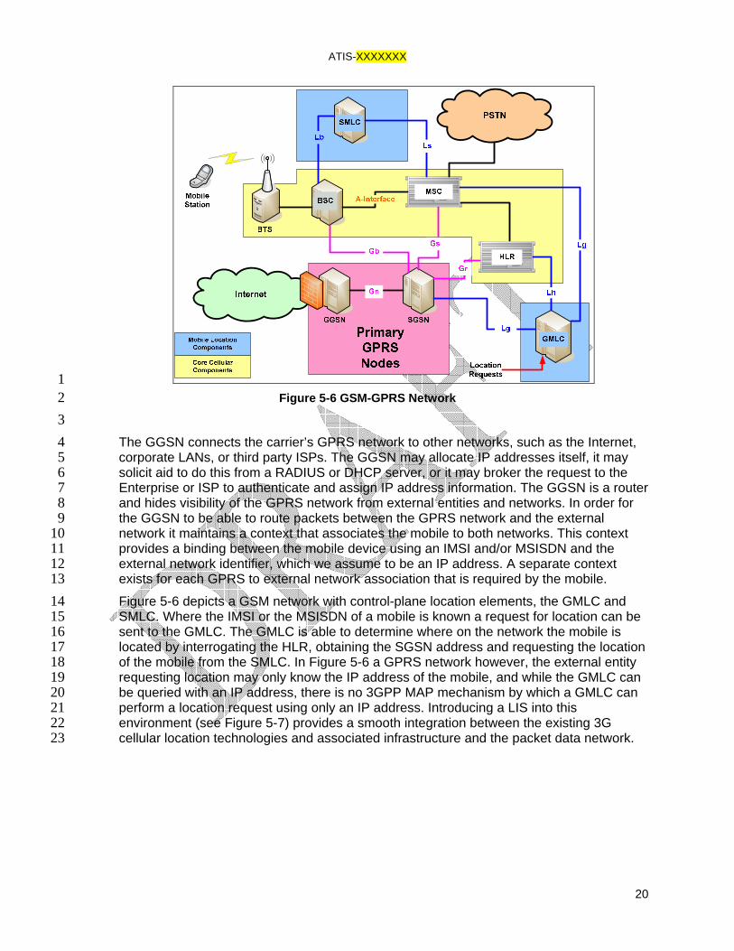
1 Figure 5-6 GSM-GPRS Network 2
3 The GGSN connects the carrier’s GPRS network to other networks, such as the Internet, 4 corporate LANs, or third party ISPs. The GGSN may allocate IP addresses itself, it may 5 solicit aid to do this from a RADIUS or DHCP server, or it may broker the request to the 6 Enterprise or ISP to authenticate and assign IP address information. The GGSN is a router 7 and hides visibility of the GPRS network from external entities and networks. In order for 8 the GGSN to be able to route packets between the GPRS network and the external 9 network it maintains a context that associates the mobile to both networks. This context 10 provides a binding between the mobile device using an IMSI and/or MSISDN and the 11 external network identifier, which we assume to be an IP address. A separate context 12 exists for each GPRS to external network association that is required by the mobile. 13 Figure 5-6 depicts a GSM network with control-plane location elements, the GMLC and 14 SMLC. Where the IMSI or the MSISDN of a mobile is known a request for location can be 15 sent to the GMLC. The GMLC is able to determine where on the network the mobile is 16 located by interrogating the HLR, obtaining the SGSN address and requesting the location 17 of the mobile from the SMLC. In Figure 5-6 a GPRS network however, the external entity 18 requesting location may only know the IP address of the mobile, and while the GMLC can 19 be queried with an IP address, there is no 3GPP MAP mechanism by which a GMLC can 20 perform a location request using only an IP address. Introducing a LIS into this 21 environment (see Figure 5-7) provides a smooth integration between the existing 3G 22 cellular location technologies and associated infrastructure and the packet data network. 23

ATIS-XXXXXXX
21
1 Figure 5-7 LIS in GPRS Network 2
Introducing a LIS and an ALE into this network assists in two ways. First, it provides a 3 means to obtain the binding between the IP address and IMSI/MSISDN which allows 4 existing GMLC/SMLC and SLP/SUPL deployments to be leveraged easily from the packet 5 data network. Second, it makes a common location acquisition architecture available, 6 allowing mobile devices to request their own location in a standard way, and for 7 applications on the Internet to locate mobile devices in the same way it would for any other 8 device in any other network. 9 The IP address to IMSI/MSISDN binding is obtained using a DHCP lease query ALE 10 similar to that described in previous sections. In this case the IMSI/MSISDN often forms 11 part of the DHCP client-identifier parameter, and can be extracted by the ALE to provide 12 the necessary information to the LIS. Location requests are then brokered from the LIS to 13 the GMLC or SLP depending on handset capabilities and network configuration. 14
5.5 Example Enterprise (Ethernet Switch/WiFi) Network 15 Wired Ethernet and WiFi are the two most common forms of physical Internet access to be 16 found in enterprise environments. They are also found in other environments such as 17 municipal Internet access services and Internet kiosks. 18
5.5.1 Wired Ethernet 19 Wired Ethernets are used extensively in enterprise networks and can be configured and 20 connected in a multitude of ways. Networks are constructed to keep inter-switch and inter-21 network traffic to a minimum so as to optimize network performance. This is done by 22 placing frequently communicating machines (hosts, computers, devices) on the same 23 switch. Where this is not possible, switches may be cascaded together and VLANs 24 introduced to keep different LAN streams on the same switch separated. 25

ATIS-XXXXXXX
22
Wired Ethernet networks are almost always combined with IP to support more 1 sophisticated addressing and routing functions. IP addresses may be statically configured, 2 or as increasingly the case, provided dynamically using DHCP [06] and a DHCP server. 3 Increasingly DHCP servers are becoming centralized functions requiring DHCP messages 4 to transit several subnets. This requirement poses some problems to hosts requiring 5 dynamically allocated DHCP addresses since broadcast messages are usually blocked by 6 IP routing functions. DHCP relays residing in layer 3 routers which turn IP broadcast traffic 7 into unicast traffic addressed directly to the DHCP server are used to resolve this problem. 8 DHCP relays are expected to operate and behave in a specified manner, and this is 9 described in [23] and [24]. In addition to providing relay functionality RFC3046 [24] 10 provides a mechanism for the relay to include information about host attachment to the 11 network. This is in the form of the switch identity associated with the relay function and the 12 port on which the DHCP broadcast request was intercepted. The degree of location 13 granularity that can be determined from this information is dependent upon how close the 14 DHCP relay function is to the edge of the network (see Figure 5-8). 15
16 Figure 5-8 Cascaded Switch Network with DHCP Relay 17
The mechanism of using DHCP relay information forms the basis of location determination 18 and subsequent delivery using the DHCP location acquisition protocol described in 19 RFC3825 [08] and its civic address counterpart [12]. 20 Another mechanism being increasingly deployed in enterprise networks is the use of an 21 ALE-type device that is provisioned with network switch configuration data, and Ethernet 22 MAC addresses it is expecting to see. These systems poll the switches periodically using 23 SNMP and generate reports of MAC address to switch port mappings (See Figure 5-9). 24 This information can then be correlated to determine the location of a physical device. This 25 method of determination is dependent of the edge switches providing SNMP management, 26 and more specifically supporting an implementation of the SNMP Bridge MIB as defined in 27 RFC1493. This MIB provides access to the switch port MAC cache information. The 28 disadvantage is that a substantial amount of configuration data is required in order to 29

ATIS-XXXXXXX
23
make this type of system work for a large network. MAC address to device binding must 1 also be configured. 2
SNMP Bridge MIBALE LISSwitch, Port, MAC
SNMP
FLAP
LEGENDPC1
Switch B
PC2 PC3
Port, MAC-ListPort, MAC-List
.
.
.Port, MAC-List
SNMP GETPort Clients
IP MAC192.168.222.5 1f0436a034ab141.209.78.56 1f0237a034fe197.111.56.11 5a1fc21df10a . . . . . .
LOC Switch Port XYZ B 2 XYA B 8 ABC B 16 . . . . . . . . .
Switch Port MAC B 2 1f0436a034ab B 8 1f0237a034fe B 16 1f0436a034ab . . . . . . . . .
Host 192.168.22.5 is at location XYZ
3 Figure 5-9 SNMP Bridge MIB ALE 4
The solution described in the previous paragraph can be augmented through the use of a 5 LIS and a DHCP lease query ALE. Here the LIS receives a location request from a specific 6 end-point and keys off the source IP address of the received packet. The LIS uses the 7 DHCP lease query ALE, described in previous sections, to obtain the IP to MAC binding. 8 Once the binding is known, switches can be interrogated to determine the switch and port 9 to which the end-device is attached. To increase search efficiency in a large network, the 10 LIS can be configured with information tying switches to specific subnets. Alternatively 11 DHCP relay information can be obtained from a lease query in addition to the IP to MAC 12 binding, again assisting with switch selection. The advantage of this approach is that no 13 pre-provisioning of MAC addresses is required, allowing deployment in a more dynamic 14 network environment. 15 The sequence of signaling associated with a LIS that combines ALEs accessing DHCP 16 lease information and SNMP bridge MIB information is shown in Figure 5-10. 17

ATIS-XXXXXXX
24
1 Figure 5-10 ALES Accessing DHCP Lease Information 2
1. The user device requests location from the LIS which picks up the device IP address 3 from the request. 4
2. The LIS requests the access location entity to provide the MAC address associated 5 with the IP address. 6
3. The access location entity utilizes a DHCP lease query request to the network’s DHCP 7 server to resolve the MAC address from the proffered IP address. 8
4. The DHCP server responds with the associated MAC address. 9 5. The LIS then requests a second (which could be physically implemented as part of the 10
first) access location entity to provide the switch and port identities that the proffered 11 MAC address are associated with. 12
6. The access location entity utilizes SNMP messaging to query the management 13 information base (MIB) in the network switch(es) to resolve the switch and port identity 14 associated with the MAC address. 15
7. The MIB on the switch hosting the MAC provides the port information in an SNMP 16 response. 17
8. The access location entity returns the host switch and port identity to the LIS. 18 9. The LIS consults an internal wiremap database to resolve the Ethernet cable 19
termination location associated with the host switch and port. 20 10. The LIS returns this location information to the user device. 21
5.5.2 Wireless Ethernet 22 Wireless Ethernet as the same suggests uses RF to communicate between the end-host 23 and the network. There are several flavors of wireless Ethernet LAN or WLAN. 24 The simplest WLAN consists of wireless access points (WAPs) connected to the ports of a 25 managed switch. End-points attach to the network through a WAP, hand-overs between 26 WAPs occurs when WAP signal strengths reach specific thresholds. Networks built in this 27

ATIS-XXXXXXX
25
fashion tend to have a relatively flat IP topology with little or no subnetting, allowing hosts 1 to easily move through the network without having to acquire a new IP address to operate 2 in a new subnet or domain. 3 More complex WLANs are constructed using a wireless network controller (WNC), which 4 controls a cluster of WAPs. In these networks the WNC controls power and client density 5 between WAPs in a similar manner to the way in which a BSC controls cell phone 6 balancing in a Cellular network. 7 Where the nominal area of coverage of a simple single deployed WiFi access point 8 represents an adequate level of granularity for location determination, then the location of 9 users can be associated with the Ethernet switch port to which the access point is 10 connected. That is, if a simple “cell-based” location is all that is required, then no WiFi 11 specific solution is required. The mechanisms described in section 5.5.1 are all that are 12 required to associate a user with the nominal location covered by the access point which is 13 connected back through an Ethernet switch port. 14 For more elaborate WiFi networks including mesh deployments involving centralized 15 network controller support, the mechanisms identified in section 5.3 are applicable as 16 there are a number of similarities in the physical characteristics of WiFi and WiMAX. As 17 with WiMAX, there is scope for further study within the IEEE. 18
6 LIS Operational Considerations 19
The conceptual role of the LIS is to provide location information (optionally digitally signed) 20 to its clients. This is straightforward from a conceptual perspective but has significant 21 operational implications. The organization that delivers broadband Internet access to users 22 may actually be made up of separate business entities and the relationship between the 23 different entities impacts the practical implementation of the, otherwise logical, LIS function 24 and has a bearing on the specific functionality that a given LIS entity will have. 25 For example, broadband DSL subscribers establish a commercial relationship with an 26 Internet Service Provider (ISP) who, for the price of the subscription, undertakes to provide 27 the DSL service to that subscriber’s residential address. The ISP, however, may not own 28 the DSL infrastructure, the copper wires and DSLAM equipment that provides the physical 29 connectivity for the subscriber. This infrastructure may be owned by a quite independent 30 Regional Broadband Provider (RBP). 31 In this situation, the ISP pays the RBP for the physical access on behalf of, and quite 32 transparently to, the subscriber. Moreover, commercial preferences may dictate that the 33 RBP does not want the ISP subscribers and applications having direct connection to, and 34 use of their LIS infrastructure. In such cases the ISP may provide a “gateway” LIS function 35 for the subscribers and applications to query. 36 The RBP operates the physical access infrastructure from which the location can be 37 determined; i.e. the RBP can determine the physical DSLAM termination and residential 38 address associated with the copper pair on that termination. A practical deployment 39 topology, then, is to have the RBP operate the LIS which actually determines the location. 40 The ISP and the RBP business entities already have a commercial relationship and data 41 interconnection as part of the general provision of Internet access that is the purpose of 42 the relationship. And, in this case, the ISP LIS will also utilize the RBP LIS infrastructure to 43 perform the actual location determination. 44

ATIS-XXXXXXX
26
The above, is just one example, of how a LIS implementation may be driven by 1 organizational and commercial imperatives. In the example given, the ISP LIS services the 2 client requests but needs to be able to communicate with the RBP LIS in order to resolve 3 actual location information. The same considerations apply for any technology which is 4 wholesaled by an infrastructure operator to an ISP, including wireless technologies such 5 as WiMAX. Just as a standard protocol for LIS-Client communications is critical, the same 6 practical requirement applies to LIS-LIS communication. 7 The following sections examine some of the practical factors that affect the 8 implementation and deployment of LIS functionality and describe a general model which 9 can be applied in determining the appropriate implementation. 10
6.1 Types of LIS and LIS Operators 11 The types of LIS operators (organizational entities that may own and operate a LIS) 12 include, though may not be limited to, the following: 13
◦ Access infrastructure providers 14 o RBPs for DSL, Cable, 3G, WiMAX etc. 15 o Municipal and community WiFi network operators 16
◦ Internet Service Providers 17 o Providers of Internet access to the public 18 o May own or use third party access infrastructure 19
◦ Geo-distributed1 LAN operators 20 o Commercial enterprise with broad geographic coverage 21 o Government enterprise operator 22 o Academic and research network operator 23 o Extensive private estate network operator 24
◦ Geo-point2 LAN operator 25 o Residential LAN 26 o Single access point hotspot 27
As described in the introductory text, the form and function of the LIS implementation in 28 each of the above cases will vary. They are taken in turn in the following sections. 29
1 No hard definition of “geo-distributed” or “broad geographic coverage is offered in this text. To an extent, this will be governed by circumstance and jurisdiction. For example, a LAN operating in a large building covering thousands of square feet may be considered a “geo-distributed” network if either the owner/operator of the building or the jurisdiction in which the building is located consider it necessary to resolve discrete locations within that building – as opposed to just a centroid geodetic location or overall civic address for the building. The owner/operator may use a LIS to track staff or assets within a hot-desk or warehouse environment. The local jurisdictions may require such large buildings to provide a more precise location than just the civic address in the case of emergency calls. If neither imperative exists, then the LAN, despite its actual size, may be regarded as a geo-point network. 2 As with “geo-distributed”, no hard definition of “geo-point” is provided in this text. Again, the question of whether a hotspot offered by a coffee shop, for example, is considered a geo-point network versus a geo-distributed one depends on circumstances including the question of how big the hotspot coverage actually is.

ATIS-XXXXXXX
27
6.1.1 Access Infrastructure Provider Network 1 In this case, we are dealing with the operator of the physical infrastructure (wired or 2 wireless) which is used by subscribers to gain access to the public Internet. The LIS in this 3 environment has the key task of determining location from the network parameters related 4 to the device to be located. It may serve the devices themselves when it comes to 5 requests for location, or it may serve a third-party device, such as an ISP LIS, with which 6 the device has a more direct relationship. 7 In terms of digitally certifying the source of the location information, and for those 8 jurisdictions where the certificate authority only provides certificates to infrastructure 9 providers, the access infrastructure LIS will need to support certificate management and 10 the signing of location information on behalf of ISP operators. The LIS will also support 11 robust authentication and authorization functions to ensure that ISP LIS instances 12 requesting location information for devices are only doing so for their own subscribers. 13 Therefore, an access infrastructure LIS needs to support all of the generic functions of a 14 LIS including location determination, location acquisition protocol support, assertion, and 15 digital certification of the source of location. It can be labeled as a “general LIS”. 16
6.1.2 Internet Service Provider 17 Where the ISP owns and operates its own access infrastructure, then the LIS 18 implementation will be as described for an access infrastructure operator LIS. However, in 19 the quite common circumstance where the ISP purchases access infrastructure wholesale 20 from another operator, the LIS may not actually perform location determination itself. In 21 this case, rather than using network parameters to calculate location, the ISP LIS makes 22 the request, with appropriate device identification parameters, to the infrastructure 23 operator LIS. The ISP LIS supports the location acquisition protocol for subscriber devices 24 and applications but it relies on the infrastructure operator LIS to obtain the location 25 corresponding to those devices. 26 The protocol used from the ISP LIS to the infrastructure operator LIS may be the standard 27 location acquisition protocol. There is an additional requirement that the ISP LIS has the 28 option to be able to provide authentication to establish the acquisition protocol session. 29 This supports the ability of the infrastructure operator LIS to properly authorize requests by 30 the ISP LIS. 31 In terms of the certification of location source, the ISP LIS may be equipped with a 32 certificate or it may request the digital certification be done by the infrastructure provider 33 on its behalf. 34 An ISP LIS, as described in this section, acts as a gateway to a general LIS where location 35 is actually determined. As such, this form of LIS can be labeled as a “gateway LIS”. 36
6.1.3 Geo-distributed LAN 37 A Geo-distributed LAN is most often labeled an “enterprise LAN”. A key characteristic of 38 such a network is that it provides access to a closed group of users. It is not typically 39 regarded as a public Internet access provider network, but it does have a connection to 40 the Internet via one or more access infrastructure provider networks. Given such a LAN is 41 connected through an access infrastructure provider, the location of devices on the LAN 42 could be provided by the LIS within that access infrastructure. However, if the LAN is 43 substantially “geo-distributed” then there is a requirement to be able to determine location 44 to discrete areas within that area of LAN coverage. Thus the idea of an enterprise LIS 45

ATIS-XXXXXXX
28
exists. Such a LIS would be able to determine more precise locations based on LAN 1 parameters associated with the subscriber device. 2 A large enterprise may actually be regarded as the equivalent of an access infrastructure 3 provider, in that the LIS may support all of the functions of a general LIS with the exception 4 of supporting ISP client LIS connections. However, for enterprises below a given size, it 5 becomes unlikely that a certificate authority could possibly proceed with issuing certificates 6 to the many candidates this would represent. Where a client device or application requests 7 a certified location the enterprise LIS will proxy the request through to the access provider 8 LIS. As such, the LIS operating with a geo-distributed LAN may be labeled a “proxy LIS”. 9
6.1.4 Geo-point LAN 10 A typical Geo-point LAN might correspond to a residential home LAN where there is no 11 requirement to refine location to any finer degree than can be determined by the access 12 provider. It is not actually necessary to operate a LIS in such an environment as, with the 13 appropriate discovery mechanism in place, the devices on a Geo-point LAN can query the 14 access provider LIS directly for location information. However, there are some benefits 15 that can be derived from operating a LIS in this LAN environment. 16 This LIS has no location determination capabilities itself, but it can act as a relay between 17 the devices and the access provider LIS, or it can act as a standalone LIS providing a 18 hard-coded location. Such a LIS can act as a single client to the access provider LIS and 19 apply optimizations such as caching location information to reduce operator LIS load and 20 to provide a backup in the event of an operator LIS outage. Indeed, this type of LIS can be 21 configured with static location information and provide rudimentary location service where 22 the access provider does not offer a LIS. 23 Since such a LIS primarily acts as a relay to the ISP LIS, it may be labeled a “relay LIS”. 24
6.1.5 Summary 25 The form and function that a specific instance of a LIS has will vary depending on the 26 nature of the network it is supporting and the role that the operator of that network plays in 27 the larger picture of Internet access. The specifics of form and function will inevitably be 28 influenced by these aspects and the business and other relationships that exist between 29 network types. 30 Some variants of LIS implementation that can be identified from these different network 31 scenarios can be labeled as 32
◦ General LIS 33 ◦ Gateway LIS 34 ◦ Proxy LIS 35 ◦ Relay LIS 36
The following diagram (Figure 6-1) shows an overall network topology illustrating the 37 relationships between these types of LIS implementations. 38

ATIS-XXXXXXX
29
1 Figure 6-1 LIS Types and associated network types 2
6.2 Certificate Security and Management 3 The “certification of location source” has been mentioned several times in the preceding 4 text. The concept behind this term is that location information provided by a LIS may 5 optionally be requested in a digitally “signed” form. The signature provides for the 6 identification of the source of the location information – for example a major access 7 infrastructure provider organization – and provides the means to determine whether the 8 location information has been tampered with (i.e. changed) between the time it was 9 generated by the LIS and the time it is received at the emergency network. 10 There is no direct connection between the emergency network and the LIS when the 11 location is provided by the user device. In order to deliver the location, and the identity of 12 the source of the location, and still be able to have confidence that they have not been 13 changed in the interim, the information needs to be secured digitally. This is done using 14 digital signatures based on public key encryption mechanisms. 15 The NENA i2 architecture identifies an agency labeled the Valid Emergency Services 16 Authority (VESA) which will control the generation, issuing, and maintenance of certificates 17 to (among others) LIS operators. It will be critical to the security of the emergency services 18 infrastructure of each jurisdiction implementing the i2 architecture to ensure that the 19 certificates issued by the certificate authority are managed with due care by both the 20 authority and the recipient organizations. 21 Such security considerations have implications for a LIS operator. For example, the 22 internal organization and procedures associated with the control of access to certificates 23 will need to ensure the data is not compromised. This will likely be best facilitated by 24 physical measures such as equipment supporting FIPS-140 level 3 [26] protection of the 25 certificates. 26

ATIS-XXXXXXX
30
The use of certificates only guarantees that the location data contained is authentic and 1 originated by the signer. Certificates do not protect against replay attacks, e.g. a 2 miscreant steals a signed location object and attaches it to any emergency call or multiple 3 calls. This attack could result in a PSAP being fooled into responding to what is thought a 4 real emergency as the location data passed the certification test. Emergency calls that 5 contain no location certification and/or a failed location certification also would need 6 careful handling so as to not deny services to a legitimate caller. 7
6.3 OSS Integration Considerations 8 Section 4 describes the manner in which the location of devices may be determined in 9 access networks based on a range of technologies. A common requirement in all of these 10 solutions is for the LIS to maintain data records which can be used to associate dynamic 11 network parameter values to information which ultimately indicates the location of the user. 12 Examples, of such records are ATM permanent virtual circuit IDs and the corresponding 13 DSLAM termination and residential address associated with them, or the MAC address of 14 a cable modem and the residential address associated with it. 15 In practice, there will be considerable effort and infrastructure associated with the 16 collection, grooming, provisioning and ongoing synchronization of such records into an 17 operator LIS. Typically, the necessary data may be stored in a range of back end 18 Operational Support Systems (OSS) ranging from network configuration platforms to 19 subscriber record databases. This aspect of LIS implementation may be the most 20 challenging aspect of LIS ownership. For example, this is already a significant challenge 21 for the operators of location platforms in cellular networks supporting the Phase 2 E9-1-1 22 requirements of those networks. 23 Since OSS implementations are often operator specific with little standardization in terms 24 of data schema or provisioning interfaces, it may be that the data provisioning functions of 25 a LIS will need to be dealt with by each individual operator. The situation could be 26 mitigated to some extent with the specification of a standard provisioning protocol for LIS 27 functions. While this does not address the thorny aspect of grooming data from its 28 manifold sources, it would at least allow for a common implementation at the LIS end of 29 the data chain. This document does not describe a common provisioning protocol but it is 30 identified as a potential candidate for further study in an appropriate SDO. 31
7 Location Acquisition Protocols 32
The term “location acquisition” refers to the process of a client device or application 33 requesting, and receiving, location information from the LIS. There are a number of 34 approaches and philosophies related to this acquisition process and the protocols that 35 support it. This section looks at various candidates: DHCP, LLDP-MED , HELD, RELO, 36 LREP-SIP and LCP. 37
7.1 Protocol Descriptions 38
7.1.1 Dynamic Host Configuration Protocol (DHCP) RFC3825 39 DHCP delivers network configuration information to an IP device. The intent is to provide 40 the device all the information it needs to utilize the IP network it has connected to; 41

ATIS-XXXXXXX
31
information such as the IP address allocated to the device, the address of the gateway 1 through which the traffic destined beyond the LAN should be sent, and/or the identity of 2 the domain name service (DNS) that can be requested to translate the names of network 3 hosts into their physical IP addresses in order to talk to them. RFC3825 describes an 4 option on DHCP that allows the device to request and receive a specific form of location 5 information (geodetic or civic). 6
7.1.2 Link Layer Discovery Protocol for Media Endpoint Devices (LLDP-MED) 7 TIA has defined extensions to the link layer discovery protocol (LLDP) to support 8 additional information elements applicable to media endpoint devices. These were termed 9 LLDP-MED and included the ability for those end point devices to be informed of the 10 location associated with, for example, the 802.3 Ethernet switch port to which they are 11 currently attached. 12
7.1.3 HTTP Enabled Location Delivery (HELD) 13 HELD is a newly proposed protocol, specifically for the purpose of supporting location 14 acquisition. It uses HTTP as one optional transport/session protocol and can be carried on 15 top of Layer 3 (IP), so the client device and server do not need to be within the same 16 subnet or broadcast domain to communicate. A BEEP binding has also been defined as 17 an optional transport/session protocol. HELD is currently an Internet draft submitted to the 18 IETF [04]. 19
7.1.4 Retrieving End-System LOcation information (RELO) 20 RELO is another newly proposed protocol and also one aimed at supporting location 21 acquisition interaction above Layer 3. RELO is currently an individual draft submitted to 22 the IETF [28]. 23
7.1.5 A Location Reference Event Package for the Session Initiated Protocol (LREP-SIP) 24 LREP-SIP is the most recently proposed protocol aimed at supporting location acquisition 25 interaction above Layer 3. It is based on the use of the presence event package for SIP 26 [30] defining a new, locationref, package. It is currently an individual draft submitted to the 27 IETF [29]. 28
7.1.6 Location Configuration Protocol (LCP) 29 LCP was defined to provide the same functionality as [08] but replacing DHCP with a new 30 IP-based protocol to carry the location request and response. The form of location 31 provided by LCP is defined to be the same as [08]. It is currently an individual draft 32 submitted to the IETF [31]. 33

ATIS-XXXXXXX
32
7.2 Location Protocol Gap Analysis Against NENA i2 Requirements 1 The following table illustrates the evaluation of various location protocols against NENA i2 2 Requirements [01] . 3
NENA Requirement
DHCP LLDP-MED HELD RELO LREP-SIP LCP
DA-1 – Mechanism for determining and acquiring location
Yes – the manner in which location is determined is not defined by DHCP
Yes – location associated with the network port is configured directly on the host most commonly using SNMP
Yes - HELD provides acquisition (FLAP provides measurements for determination)
Yes – the manner in which location is determined is not defined by RELO
Yes – the manner in which location is determined is not defined but the protocol supports the provision of network parameters by the device – currently only supports switch chassis/port.
Yes – the manner in whiclocation is determined is ndefined by LCP
DA-2 – Use location estimate
Yes Yes Yes Yes Yes Yes
DA-3 – Location requested any time
Yes Yes Yes Yes Yes Yes
DA-4 – Consistent method across all network configurations
No
Since DHCP is not applicable in all network technologies therefore this acquisition mechanism cannot apply to all access networks.
No
Since LLDP-MED is not applicable in all network technologies therefore this acquisition mechanism cannot apply to all access networks.
Yes Yes Yes The network identifier types are important to location determination. Currently only supports switch chassis/port.
Yes
DA-5 – Applicable to emergency services
Yes
Does not convey uncertainty.
Yes
Does not convey uncertainty.
Yes Yes Yes Yes
Does not conveuncertainty.
DA-6 – Support i2 and i3
Yes Yes Yes Yes Yes Yes
DA-7 – Provide fallback or last known
Non Applicable Non Applicable Non Applicable Non Applicable Non Applicable Non Applicable
DA-8 – Minimal call processing impact
Yes Yes Yes Yes Yes Yes

ATIS-XXXXXXX
33
NENA Requirement
DHCP LLDP-MED HELD RELO LREP-SIP LCP
DA-9 – Assert on behalf of
No No Yes (using third party terminal address value – On Behalf Of type request)
No No No
DA-10 – No Hardware modification
No No Yes Yes Yes Yes
DA-11 – No Hardware replacement
Non Applicable Non Applicable Non Applicable Non Applicable Non Applicable Non Applicable
DA-12 – Request response time
No No Yes No No No
Rep-1 – Request by reference and by value
Partial, DHCP does not support by-reference
Partial, LLDP-MED does not support by-reference
Yes Partial, RELO does not support by-reference
Yes Partial, LCP does not suppolocation-by-reference
Rep-2 – Support all fields of PIDF-LO
No
Method, presentity, rules, provided-by are not supported.
No
Method, presentity, rules, provided-by are not supported.
Yes No
RELO uses opengis GML and pidf civilLoc forms only.
Yes No
Method, presentity, ruleprovided-by arenot supported.
Rep-3 – Backwards compatibility
No
Can only support change through BIS of option or a new option
No
Can only support change through BIS of option or a new option
Yes (PIDF-LO definition evolves independently of HELD acquisition protocol)
Yes by indirection to GML and civilLoc forms
Yes (PIDF-LO definition evolves independently of LREP-SIP acquisition protocol)
No
Can only suppochange throughBIS of [08]
Rep-4 – Provide altitude and floor
Yes Yes Yes Yes Yes Yes
LocSec-1 – Provide only to authorized and authenticated devices
Yes
Can only provide location to the end-point
Yes
Can only provide location to the end-point
Yes Yes
Can only provide location to the end-point
No
Protocol forbids the use of authentication for location dereferencing
Yes
Can only providlocation to the end-point
LocSec-2 – Preserve privacy
Yes (except in transmission since location can only be transferred by-value and not by-reference)
Yes (except in transmission since location can only be transferred by-value and not by-reference)
Yes Yes (except in transmission since location can only be transferred by-value and not by-reference)
No
Protocol does not support the provision of access rules
Yes (except in transmission since location can only be transferred by-value and not breference)

ATIS-XXXXXXX
34
NENA Requirement
DHCP LLDP-MED HELD RELO LREP-SIP LCP
LocSec-3 – Location Dependable
No
No dependability mechanism exists for a PIDF-LO crafted by the end-point
No
No dependability mechanism exists for a PIDF-LO crafted by the end-point
Yes (through signed location request mechanism with PIDF-LO delivered fully-constituted by the LIS)
No
No dependability mechanism exists for a PIDF-LO crafted by the end-point
No
There is no support for signed location or for provision of credentials on dereferencing
No
No dependabilmechanism exists for a PIDF-LO crafteby the end-poin
LocSec-4 - Authentication of LIS
Partial
DHCP can provide integrity through [19], but not secrecy
No Yes (through encryption of appropriate attributes in creation of location signatures)
No No No
LocSec-5 – Source authenticated
No No Yes (credentials associated with signed location indicate the source of the location. A user provided location may be “asserted” and subsequently signed by the LIS)
No No No
LocSec-6 – Refresh cached location
Yes Yes Yes Yes Yes Yes
LocSec-7 – Privacy policies for location by reference
Not applicable
DHCP does not support location by-reference
Not applicable
LLDP-MED does not support location by-reference
Yes Not applicable
RELO does not support location by-reference
No Not applicable
LCP does not support locatioby-reference
1
7.3 Findings 2 Of the 23 NENA provided applicable requirements [18] on location acquisition and 3 determination: 4
• DHCP provides full support for 10 and partial support for 2, but cannot support the 5 remaining 8. Three requirements are not applicable. 6
• LLDP-MED provides full support for 10 and partial support for 1, but cannot support 7 the remaining 9. Three requirements are not applicable. 8
• HELD provides full support for 21, two requirements are not applicable. 9

ATIS-XXXXXXX
35
• RELO provides full support for 13 and partial support for 1. It does not support 6 1 and 3 are not applicable. 2
• LREP-SIP provides support for 13 but does not support 8. Two requirements are 3 not applicable At time of writing, it was not clear whether the user agent identifier 4 exchange is fundamental to location determination or not. The compliance figures 5 assume it is not, or else there would be lower compliance. 6
• LCP provides support for 12 and partial support for 1. It does not support 7 7 requirements and 3 are not applicable. 8
In addition, to support mobile devices requiring a mid-call location update, a location 9 reference is the only practical solution and this mechanism is not supported by DHCP, 10 LLDP-MED, RELO, or LCP. 11
7.4 HELD Status 12 HELD has been submitted as an Internet draft over several increments in the 18 month 13 period up until the publication of this TR. It was submitted within the Geopriv working 14 group since that group was defining the location object extensions for the IETF presence 15 information data format. Discussion is currently focused on the question of whether a 16 location acquisition protocol that works above Layer 3 should be defined. A special sub 17 working group (the Layer 7 location protocol group) has been formed to discuss this 18 aspect before further definition of the protocol can progress. 19
8 Location Parameter Conveyance 20
Regardless of the location acquisition protocol used to communicate location information 21 to devices and applications, the LIS in a given network needs to be able to determine the 22 location of the device. While the location acquisition protocol is ideally access technology 23 independent, it is necessary to deal with technology dependent specifics in order to 24 determine location in a specific access network. The manner in which the location of a 25 given IP address is determined in a DSL network is, of necessity, different than the 26 manner in which it is determined in a WiMAX network. 27 When it comes to using the network to determine location, all of the technologies do have 28 one key characteristic in common. They all need to provide the value of some set of 29 network parameters associated with the target IP address in order that the LIS can 30 determine the location for that IP address. Section 4 describes the different sorts of 31 network parameters that may be used (Ethernet switch and port identities, L2TP and ATM 32 circuit identities, modem MAC addresses, wireless network access point identities and 33 radio parameter values being some examples). 34 To capitalize on this common characteristic, a logical network function called an Access 35 Location Entity (ALE) can be defined. The function of the ALE is to provide the LIS with the 36 set of network parameters pertinent to location determination for the particular type of 37 access network with which the ALE is associated. While the ALE is technology specific, 38 the communication of a “set of network parameters” to the LIS is a common function. For 39 this purpose, the Flexible LIS-ALE Protocol (FLAP) is proposed. 40

ATIS-XXXXXXX
36
8.1 LIS-ALE Architecture 1 As indicated above, the ALE is a logical entity dealing with the specific function of 2 extracting and providing the pertinent network parameter values for location determination 3 and sending these parameters to the LIS – see Figure 8-1. The ALE is a logical entity and, 4 as such, the manner in which the ALE is implemented is not prescriptive. However, the 5 ALE abstracts the implementation specifics so the parameters are conveyed in a standard 6 way using FLAP. 7 A LIS instance provides location services support for users of a specific access network or 8 set of access network technologies. As such, the LIS has a relationship with all the ALE 9 instances supporting the access network(s) for which it provides service. 10 As part of the ongoing operation of the network; 11
• the ALE functions may asynchronously report all events pertinent to location 12 determination, with at least some measurements including the IP address of 13 devices against which these parameters can be correlated, 14
• the LIS may poll the ALE functions for such parameter values on an ongoing 15 basis, or 16
• the LIS may specifically poll the ALE in response to a client request for location. 17 18 The FLAP definition supports all of these modes of operation. 19
20 Figure 8-1 The General LIS-ALE Architecture 21

ATIS-XXXXXXX
37
8.2 FLAP Protocol 1 The Flexible LIS-ALE Protocol (FLAP) was designed to provide a framework for reporting 2 location measurements. 3
8.2.1 FLAP Description 4 It is useful to realize that, at any point along the location determination chain, one piece of 5 information is known and the other is required. FLAP names the known component 6 terminal information, that is, the information identifies a particular terminal. The unknown 7 part relates to how the terminal accesses the network, and is called access information. 8 The ALE is responsible for providing access information when given terminal information. 9 For example, if an ALE in an Ethernet switch is queried, it can provide a link between a 10 MAC address and/or IP address (terminal information) and a switch and port (access 11 information). 12 The distinction between terminal and access information is a simplification that can be 13 thought of as a key-value pair. The link between these values is provided by the ALE. 14 FLAP provides a framework for reporting this link between terminal and access 15 information. 16 FLAP is defined as a BEEP profile (Blocks Extensible Exchange Protocol) (RFC3080, 17 RFC3081). BEEP is a protocol framework providing bi-directional, asynchronous 18 communication between two entities, in this case a LIS and ALE. BEEP is based on TCP, 19 with support for Transport Layer Security (TLS) where additional security is required. 20 In order to keep all configuration data centralized, the LIS initiates the BEEP connection. 21 The only configuration that may be required at the ALE is that which permits the 22 authentication of the LIS. Using the Pre-Shared Key Ciphersuites for Transport Layer 23 Security (TLS) (RFC 4279) means that all configuration maintenance effort is kept at the 24 LIS. 25 By using XML-formatted messages, FLAP can be easily extended to accommodate 26 different access network technologies. The base specification does not proscribe what 27 terminal and access information look like, except to provide start and end times for access 28 information. Terminal and access elements provide a generic container that can be 29 redefined depending on the access network technology. A technology extension defines 30 what information is required for each of terminal and access for that technology. 31 Vendor extensions are added on top of technology extensions and allow for 32 enhancements to FLAP that are specific to particular ALEs or networks. Vendor 33 extensions can be used for proprietary methods of improving the speed, accuracy or 34 security of location determination. 35 Technology and vendor extensions are distinguished by using Namespaces for XML. Each 36 extension is uniquely identified by a URN that is recognized by the LIS. 37 FLAP allows different ALE types to report location measurements as best suits them. 38 Different FLAP message types, defined in the base FLAP schema, can be used to convey 39 location measurements both asynchronously and synchronously. 40

ATIS-XXXXXXX
38
8.2.2 Supported FLAP Messages 1 Notification 2 The Notification message Figure 8-2 can be generated by the ALE when it detects: a 3 terminal entering the network, a terminal moving within the network, or a terminal leaving 4 the network. This is the recommended approach to ensure an ALE reports location 5 parameters as network circumstances change. 6
7 Figure 8-2 The ALE-to-LIS Notification Message Flow 8
9 LIS to ALE Notifications (a specific use case) 10 In some cases, the LIS might detect a particular terminal has moved out of the of network 11 coverage the LIS supports (referred to in this document as the “network sector”) monitored 12 by an ALE before the ALE detects this change. This might be reported to the LIS by 13 another ALE. For instance, DHCP may not always recognize when a terminal has left the 14 network sector. DHCP clients are not obliged to notify the server when they leave the 15 network sector, so many do not. 16 In this case a LIS to ALE, or downstream, notification message can be sent to the ALE. 17 This message is optional, and is provided as a courtesy to the ALE. The ALE can use this 18 message as a trigger to release any resources it has committed in monitoring that terminal 19 and to update any state it maintains. The downstream notification also prevents the ALE 20 from erroneously reporting the presence of the terminal. 21 Resynchronization 22 Network or system outages are inevitable in virtually any system, particularly one that is 23 intended for continuous usage. Resynchronization enhances the robustness and reliability 24 of LIS and ALE communications by providing the LIS a means to quickly determine the 25 current state of the ALE at startup time and after an outage. 26 Resynchronization uses the BEEP MSG/ANS exchange, which allows for multiple 27 responses to a single request. A Resynchronization Request from a LIS can result in any 28 number of Resynchronization Response messages being sent by the ALE. Each 29 Resynchronization Response contains information about a single terminal and network 30 attachment. 31 A Resynchronization procedure Figure 8-3 can be used in two ways: a full 32 Resynchronization is used at startup time, or after a long outage; a partial 33 Resynchronization can be used for short outages caused by a transitory fault, or 34 communications error. 35

ATIS-XXXXXXX
39
When a LIS starts, it will probably not have any useful information about the state of the 1 network. The “full” Resynchronization procedure provides the current state of all network 2 attachments the ALE can monitor. 3 After a short outage in either the LIS or the LIS to ALE link, the LIS can use the partial, or 4 “since”, Resynchronization procedure to request those notifications it might have missed. 5 The partial Resynchronization Request includes a start time, which triggers different 6 behavior at the ALE. 7 The partial Resynchronization differs from a full Resynchronization because the LIS 8 already has some information about the state of the network – the ALE only needs to 9 provide the changes that have occurred since the indicated time. In effect, the ALE needs 10 to send all the Notifications it would have sent during the request period. This usage differs 11 because responses to this sort of request include terminals leaving the network sector. 12 Partial Resynchronization is an optimization that reduces the impact of temporary outages. 13 If this mode is not supported, the LIS can purge its current state and use the full 14 Resynchronization. 15 These messages require that the ALE perform tasks beyond just reporting changes in the 16 network. In order to support these messages, the ALE needs to maintain certain 17 information. For the first usage, the ALE needs to maintain an image of the current state of 18 the network sector. The second usage requires that the ALE also remember a certain 19 number of the most recent Notification messages it has sent, or might have sent. 20 Alternatively, ALE implementations can avoid storing any additional information, providing 21 they support the Access Query, which can be used by the LIS to build an image of the 22 state of the network sector. However, this option increases the impact of an outage by 23 requiring more messaging to recover state after the outage. 24
25 Figure 8-3 The LIS-to-ALE Resynchronization Message Flow 26
27 Access Query 28 The Access Query is a synchronous query that is provided to deal with limitations of ALE 29 implementations. The LIS can make a direct request to the ALE to obtain location 30 parameters. The Access Query is sent by the LIS, and includes terminal information only. 31

ATIS-XXXXXXX
40
The Access Query procedure Figure 8-4 can be used in a number of ways to address 1 ALEs with limited functionality. Therefore, an Access Query can be used to check that a 2 terminal is still attached to a network sector. 3 If an ALE does not generate Notification messages, an Access Query can be used to 4 retrieve parameters. The LIS can poll for information from the ALE, or request information 5 on demand. Using Access Query in this fashion can consume a large amount of network 6 resources, and therefore is not recommended. 7
8 Figure 8-4 The LIS-to-ALE Access Query Message Flow 9
10 The set of messages defined in the base FLAP XML schema are designed to provide 11 flexibility. Effective ALE implementations and LIS-ALE inter-working can be set up based 12 on the practicalities surrounding the ALE implementation and the most optimal approach 13 to obtaining location parameter information from specific network types. Most ALEs and 14 LIS implementations would not be expected to utilize all of the defined message types. 15 16
8.3 FLAP Examples 17 The following message uses the Ethernet extension with additional vendor extension 18 parameters to do a notification message: 19 <ntfy xsi:type=”enet:ntfy” 20 xmlns:vnd1=”http://www.example.com/flap/terminal/hw” 21 xmlns:vnd2=”http://www.example.com/flap/access/skew”> 22 <enet:terminal 23 <ip>192.168.0.1</ip> 24 <enet:hwaddr>12:34:56:78:90:ab</enet:hwaddr> 25 <vnd1:hw revision="1.2"/> 26 </enet:terminal> 27 <enet:access time="2005-04-14T10:51:23.000+10:00"> 28 <enet:switch><ip>192.168.0.1</ip></enet:switch> 29 <enet:port>4</enet:port> 30

ATIS-XXXXXXX
41
<vnd2:skew>0.5127</vnd2:skew> 1 </enet:access> 2 </ntfy> 3 4 The following is an example of an Access Query. It includes information about a particular 5 terminal that location parameters are being requested for: 6 MSG 1 0 . 63 176 7 Content-Type: application/xml 8 9 <aq xsi:type="dhcp:aq"> 10 <dhcp:terminal> 11 <ip>192.168.2.10</ip> 12 <dhcp:hwaddr>01020304050a</dhcp:hwaddr> 13 </dhcp:terminal> 14 </aq> 15 END 16 The response to this message does not necessarily contain any terminal information: 17 RPY 1 0 . 801 294 18 Content-Type: application/xml 19 20 <aqr result="200" xsi:type="dhcp:aqr"> 21 <dhcp:access time="2005-04-15T14:02:25.160+10:00" 22 expires="2005-04-15T16:02:25.160+10:00"> 23 <dhcp:relay>192.168.2.1</dhcp:relay> 24 <dhcp:circuit-id>03</dhcp:circuit-id> 25 </dhcp:access> 26 </aqr> 27 END 28 The following is an example of a Resynchronization message sent by the LIS. The since 29 attribute indicates to the ALE that this is a partial Resynchronization starting at the given 30 time. 31 MSG 1 0 . 0 108 32 Content-Type: application/xml 33 34 <sync since="2005-04-15T14:51:21.000+10:00" 35 xsi:type="dhcp:sync"/> 36

ATIS-XXXXXXX
42
END 1 The ALE responds to this request by providing a number of responses, each contained in 2 a separate BEEP frame, followed by a NUL frame: 3 ANS 1 0 . 0 411 4 Content-Type: application/xml 5 6 <syncr result="200" xsi:type="dhcp:syncr"> 7 <dhcp:terminal> 8 <ip>192.168.2.11</ip> 9 <dhcp:hwaddr>01020304050b</dhcp:hwaddr> 10 </dhcp:terminal> 11 <dhcp:access time="2005-04-15T15:01:10.991+10:00" 12 expires="2005-04-15T17:01:10.991+10:00"> 13 <dhcp:relay>192.168.2.1</dhcp:relay> 14 <dhcp:circuit-id>02</dhcp:circuit-id> 15 </dhcp:access> 16 </syncr> 17 END 18 ANS 1 0 . 411 253 19 Content-Type: application/xml 20 21 <syncr result="201" xsi:type="dhcp:syncr"> 22 <dhcp:terminal> 23 <ip>192.168.2.12</ip> 24 <dhcp:hwaddr>01020304050c</dhcp:hwaddr> 25 </dhcp:terminal> 26 <dhcp:access time="2005-04-15T15:17:57.521+10:00"/> 27 </syncr> 28 END 29 NUL 1 0 . 664 0 30 END 31
8.4 Considerations of FLAP versus “Technology Specific Solutions” 32 While FLAP does not address the specifics of how location parameters are identified and 33 extracted from a given access network type, it does provide a consistent framework by 34 which these parameters may be conveyed to a LIS. 35

ATIS-XXXXXXX
43
Advantages of this approach to delivering location parameters to a LIS compared to 1 implementing technology specific protocols from the access network elements to the LIS 2 include the following: 3
• FLAP provides a common conceptual framework and language which facilitates 4 the communication of requirements and capabilities between network operators 5 and network equipment vendors. 6
• Network operators can utilize a common LIS infrastructure supporting multiple 7 access network technology variations without requiring vendor-specific protocol 8 support to handle the delivery of location parameters. The LIS still needs to be able 9 to understand the significance of the parameters delivered by a vendor network 10 ALE. 11
• The cost associated with LIS implementations and the speed of deployment will be 12 reduced if there is a common LIS-ALE protocol. 13
• Cross-vendor (LIS-ALE) interoperability will be less complex with a common inter-14 working protocol. 15
• Network equipment vendors will be able to highlight product differentiators more 16 readily by documenting the FLAP extensions (and related benefits for location 17 determination) supported by their products. 18
8.5 Status of FLAP 19 FLAP is currently only informally documented [27] and has not been specified under the 20 auspices of any SDO. Location measurement has, in the past, typically been done on a 21 technology specific basis. 22 For example, the Base Station system Application Part- Location Services Extension 23 (BSSAP-LE) and Base Station system (BSSLAP) 3GPP protocols define the messaging 24 used to communicate GERAN related location parameters. FLAP spans an arbitrary set of 25 access technologies and, consequently, is not specific to any particular technology-26 focused SDO or forum. To provide a definitive specification for FLAP, a general SDO body 27 is most appropriate but there is no value in specifying FLAP unless the technology-28 focused organizations actually endorse the use of FLAP to support location parameter 29 conveyance for the access technologies they support. ESIF recommends that FLAP be 30 adopted for implementation. 31
9 References 32
[01] NENA VoIP-Packet Technical Committee, “Interim VoIP Architecture for Enhanced 33 9-1-1 Services (i2),” NENA 08-001, Dec 2005. 34
[02] NENA Technical Committee Chairs, “Implementation of the Wireless Emergency 35 Service Protocol E2 Interface,” NENA 05-001, Dec 2003. 36
[03] TIA-1057 TIA, “Link Layer Discovery Protocol for Media Endpoint Devices (LLDP-37 MED),” TR 41.4 38
[04] Winterbottom, J., Thomson, M., and B. Stark, “HTTP Enabled Location Delivery 39 (HELD),” draft-winterbottom-http-location-delivery-04 (work in progress), October 40 2006. 41

ATIS-XXXXXXX
44
[05] Polk, J. and B. Rosen, “Session Initiation Protocol Location Conveyance,” draft-ietf-1 sip-location-conveyance-05 (work in progress), October 2006. 2
[06] Droms, R., “Dynamic Host Configuration Protocol,” RFC 2131, March 1997 (TXT, 3 HTML, XML). 4
[07] Patrick, M., “DHCP Relay Agent Information Option,” RFC 3046, January 2001. 5 [08] Polk, J., Schnizlein, J., and M. Linsner, “Dynamic Host Configuration Protocol 6
Option for Coordinate-based Location Configuration Information,” RFC 3825, July 7 2004. 8
[09] Peterson, J., “A Presence-based GEOPRIV Location Object Format,” RFC 4119, 9 December 2005. 10
[10] Thomson, M. and J. Winterbottom, “Revised Civic Location Format for PIDF-LO,” 11 (work in progress), April 2006. 12
[11] Thomson, M., “Geodetic Shapes for the Representation of Uncertainty in PIDF-LO,” 13 (work in progress), May 2006. 14
[12] Schulzrinne, H., “Dynamic Host Configuration Protocol (DHCPv4 and DHCPv6) 15 Option for Civic Addresses Configuration Information,” (work in progress), January 16 2006. 17
[13] Winterbottom, J., Tschofenig, H., and M. Thomson, “GEOPRIV PIDF-LO Usage 18 Clarification, Considerations and Recommendations,” (work in progress), May 2006. 19
[14] Winterbottom, J., Peterson, J., and M. Thomson, “Rationale for Location by 20 Reference,” (work in progress), January 2006. 21
[15] DSL Forum, “Core Network Architecture Recommendations for Access to Legacy 22 Data Networks over ADSL,” Technical Report 025. 23
[16] DSL Forum, “Migration to Ethernet-Based DSL Aggregation,” Technical Report 101. 24 [17] Cuellar, J., Morris, J., Mulligan, D., Peterson, J., and J. Polk, “Geopriv 25
Requirements,” RFC 3693, February 2004. 26 [18] NENA Requirements for Location Information to Support Emergency Services, 13 27
November 2006. 28 [19] Droms, R. and W. Arbaugh, “Authentication for DHCP Messages,” RFC 3118, June 29
2001. 30 [20] NENA VoIP, Recommended Method(s) for Determining Location to Support 31
Emergency Calling Technical Information Document, Draft 30 May 2006. 32 [21] Woundy, R. and K. Kinnear, “Dynamic Host Configuration Protocol (DHCP) 33
Leasequery,” RFC 4388, February 2006. 34 [22] "IP Location; Geographic Location Measurement, Delivery and Conveyance", 35
Dawson, Winterbottom , Thomson; Osbourne-McGraw-Hill; ISBN: 007226376 36 [23] Wimer, W., “Clarifications and Extensions for the Bootstrap Protocol,” RFC 1542, 37
October 1993. 38 [24] Patrick, M., “DHCP Relay Agent Information Option,” RFC 3046, January 2001. 39 [25] Decker, E., Langille, P., Rijsinghani, A., and K. McCloghrie, “Definitions of 40
Managed Objects for Bridges,” RFC 1493, July 1993. 41 [26] National Institute of Standards and Technology (NIST) – Federal Information 42
Processing standard 140 version 140-2, May 2001. 43 [27] Dawson, Winterbottom, Thomson, “IP Location”, McGraw-Hill Publishing, 2006 44 [28] Schulzrinne, H., “RELO: Retrieving End System Location Information”, draft-45
schulzrinne-geopriv-relo-01.txt, October 22, 2006 46

ATIS-XXXXXXX
45
[29] Schulzrinne, H., “A Location Reference Event Package for the Session Initiated 1 Protocol (SIP),” draft-schulzrinne-geopriv-locationref-00.txt, October 17, 2006 2
[30] Rosenberg, J., “A Presence Event Package for the Session Initiation Protocol (SIP),” 3 RFC 3856, August 2004. 4
[31] Linsner, M. Schnizlein, J., “Location Configuration Protocol (LCP),” draft-linsner-5 geopriv-lcp-01, November 7, 2006 6
7