Embed Size (px)
Citation preview

ELECTRON BEAM BASIC CONCEPTS
Dr.M.RAVIKUMAR
Professor & Head
Department of Radiation Physics
Kidwai Memorial Institute of Oncology
Hosur Road, Bangalore-560 029.
1

OUTLINE..�Basics of electron Beam
�Dose distribution in water
�Dose distribution in patients�Dose distribution in patients
�Effect of tissue heterogeneity
�Treatment Planning
2

CLINICAL ELECTRON BEAM� Delivers a reasonably uniform dose from the surface to a
specific depth , after which dose falls off rapidly, eventually to a near-zero value.
� Using electron beams allows disease within � Using electron beams allows disease within approximately 6 cm of the surface to be treated effectively, sparing deeper normal tissues.
� Electrons have been used in radiotherapy since the early 1950s.
� Modern high-energy linacs typically provide, in addition to two photon energies, several electron beam energies in the range from 4-25 MeV
3

CLINICAL USE� Electrons are useful in treating cancer of the skin and lips,
upper-respiratory and digestive tract, head and neck, breast
� Skin : Eyelids, nose, ear, scalp, limbs. � Skin : Eyelids, nose, ear, scalp, limbs.
� Upper-respiratory and digestive tract: Floor of mouth, soft palate, retromolar trigone, and salivary glands
� Breast: Chest-wall irradiation following mastectomy; Nodal irradiation, Boost to the surgical bed
� Other sites: Retina, orbit, spine (craniospinal irradiation), Pancreas and other abdominal structures (intraoperativetherapy) Cervix (intracavitary irradiation)
4

ELECTRON BEAM PRODUCTION
5
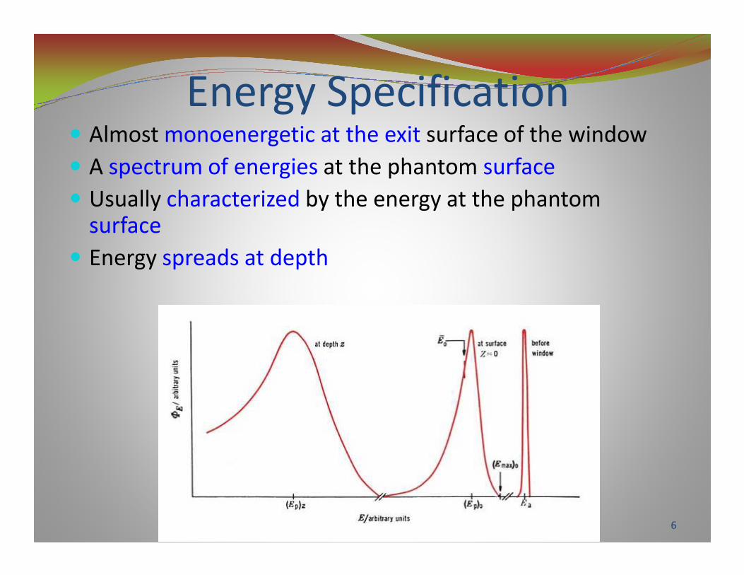
Energy Specification� Almost monoenergetic at the exit surface of the window
� A spectrum of energies at the phantom surface
� Usually characterized by the energy at the phantom surface
� Energy spreads at depth
6

Energy SpecificationMost Probable Energy
� (Ep)0 = C1 + C2Rp + C3Rp2
(Ep)0 the most probable energy at the phantom surface
Rp the practical range in centimeters
For water, C1=0.22 MeV, C2=1.98 MeV cm-1,
C3=0.0025 MeV cm-2C3=0.0025 MeV cm-2
Mean Energy
5040 RCE = for water, C4= 2.33 MeV
Energy at DepthThe most probable energy and the mean energy of
the spectrum decreases linearly with depth.)1(0
p
zR
zEE −=
7

INTERACTION WITH MEDIUM
� Interact with atoms by a variety of processes owing
to Coulomb force interactions.
The processes are
� (a) inelastic collisions with atomic electrons
( ionization and excitation ),
� (b) inelastic collisions with nuclei ( bremsstrahlung ),
� (c) elastic collisions with atomic electrons, and
� (d) elastic collisions with nuclei.
8

COLLISIONAL & RADIATIVE LOSS� An electron traveling in a medium loses energy as a result
of collisional and radiative processes.
� Collisional Losses (Ionization and Excitation) The rate of energy loss depends on the electron density of the medium.
� The rate of energy loss/gm/cm2, which is called the mass � The rate of energy loss/gm/cm , which is called the mass stopping power, is greater for low atomic number (Z) material.
� Radiation Losses (Bremsstrahlung) The rate of energy loss per centimeter is approximately proportional to the electron energy and Z2.
� Moreover, the probability of radiation loss relative to the collisional loss increases with the electron kinetic energy and with Z.
9

Output Calibration
� Ion Chamber
� Plane-parallel ionization chambers for energies less than 10 MeV
� Plane-parallel or cylindrical chambers for higher-energy beamsenergy beams
� Phantom
� Water, or plastic phantoms such as polystyrene and Lucite
� Dimensions large enough to provide full scatter for all field sizes and energies
10
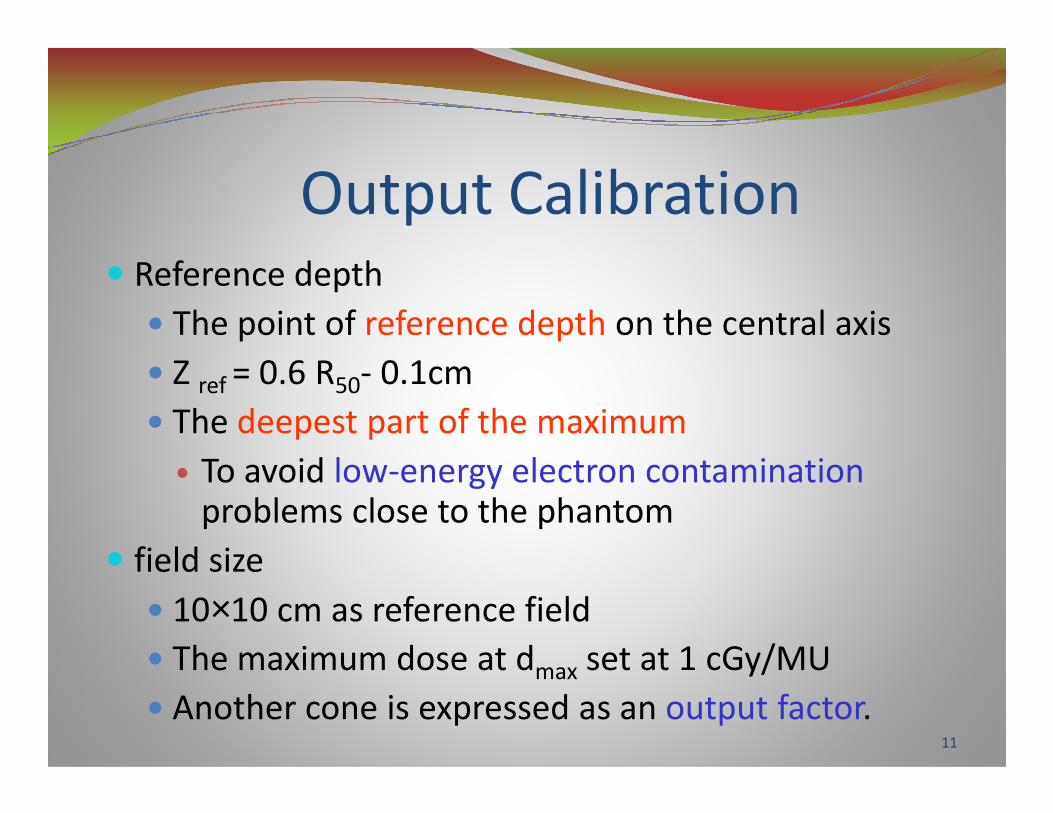
Output Calibration� Reference depth
� The point of reference depth on the central axis
� Z ref = 0.6 R50- 0.1cm
� The deepest part of the maximum� The deepest part of the maximum
� To avoid low-energy electron contaminationproblems close to the phantom
� field size
� 10×10 cm as reference field
� The maximum dose at dmax set at 1 cGy/MU
� Another cone is expressed as an output factor.11

Dose distribution in water
12

Electron beam PDD
13
Components in PDD
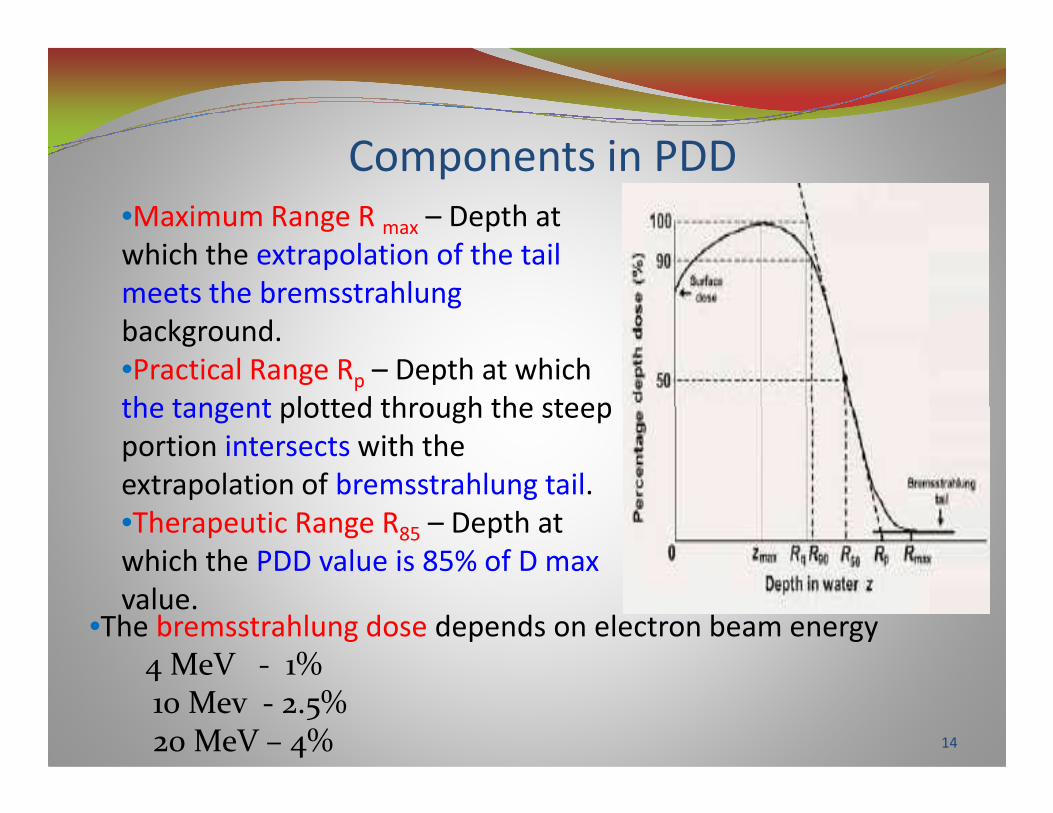
•Maximum Range R max – Depth at
which the extrapolation of the tail
meets the bremsstrahlung
background.
•Practical Range Rp – Depth at which
the tangent plotted through the steep the tangent plotted through the steep
portion intersects with the
extrapolation of bremsstrahlung tail.
•Therapeutic Range R85 – Depth at
which the PDD value is 85% of D max
value.•The bremsstrahlung dose depends on electron beam energy
4 MeV - 1% 10 Mev - 2.5%20 MeV – 4% 14

Continued…� The depth in cm at which electrons deliver a dose 85%
isodose level , is equal to approximately one-third of the electron energy in MeV.
� The range of electrons in cm is equal to approximately one half of the electron energy in MeV.
� The rate of energy loss is about 2 MeV/cm� The rate of energy loss is about 2 MeV/cm
� Most useful treatment depth, or therapeutic range , of electrons is given by the depth of the 85% depth dose.
� Because the dose decreases abruptly beyond the 85% dose level, the treatment depth and the required electron energy must be chosen very carefully .
� The guiding principle is that, when in doubt, use a higherelectron energy to make sure that the target volume is well within the specified isodose curve.
15

Energy dependence of depth dose
•The Percentage Depth dose
increases as the energy
increases.increases.
• However, unlike the
photon beams , the percent
surface dose for electrons
increases with energy.
16

Field Size dependence of Depth dose
•Depth dose has a significant
dependence on field size, and the
dependence varies with incident
electron energy.
• Loss of side-scatter equilibrium ,
results in R90 shifting toward the surfaceresults in R90 shifting toward the surface
as field size decreases .
• The shift also increases the R90-10
distance, as R10 changes only slightly.
•As the field size gets even smaller, the
maximum dose decreases, and when it
is normalized to 100%, the relative dose
at the surface, Ds, increases.
17

Electron Source� Virtual source
� An intersection point of the backprojections along the most probable directions of electron directions of electron motion at the patien
� The Virtual SSD helps to predict dose at extended SSDs
� The Virtual SSD is a function of FS and energy
18

Virtual source
)( 20 ++= m gdfI
Effective SSD
To correct air gap
1
)(
0
20
++
=
+++=
mg
m
m
g
df
g
I
I
df
gdf
I
I
A function of energy and FS
19

Output variation with Field size
� The dose increases with field size because of the increase scatter from the collimator and phantom.
� Various size cone with a � Various size cone with a fixed jaw opening minimizes the variation of collimator scatter.
� If the x-ray jaw setting changed with the field, the output would vary widely, especially for lower-energy beam.
20

Field Size Dependence
� If the distance between the point of measurement and the edge of the field is shorter than the range of the laterally scattered the laterally scattered electrons
⇒phantom scatter↓⇒The effects of field size on
output and the central axis depth dose curve is significant.
Primary collimator fixed,
secondary collimators
(trimmers) close to the
phantom varied to change
the field size21

Isodose curves•As electron beam penetrates the
isodose curves expands due to
scattering.
•Low value isodose curves
(<20%)bulges out as the result of
increase in electron scattering
angle with decreasing electron angle with decreasing electron
energy.
•Above 15 MeV electrons exhibit
lateral constriction of higher value
isodose curves (>80%)
•Penumbra is the distance between
80%-20% isodose level at a depth
of R85/2
22

SSD dependence of depth dose•Depth-dose variations with SSD
are usually insignificant .
•Differences in the depth dose
resulting from inverse square effect
are small because electrons do not
penetrate that deep .
•The significant growth of
penumbra width with SSD restricts
the SSD in clinical practice to
typically 115 cm or less.
•The primary effect of inverse
square is that R90 penetrates a few
millimeters deeper at extended SSD
at the higher energies .
23

Choice of Field Size
� A significant tapering of the 80% isodose curve at energies above 7 MeV
� The constriction of the � The constriction of the useful treatment is worse for the smaller fields.
� A larger field at the surface may be necessary to cover a target area adequately.
24

Dose distribution in patient � The ideal irradiation condition is for the electron beam to be
incident normal to a flat surface with underlying
homogeneous soft tissues , which is seldom encountered
clinically.
� As the angle of incidence deviates from normal, as the surface
becomes irregular , and as internal heterogeneous tissues becomes irregular , and as internal heterogeneous tissues
(e.g., air, lung, and bone) become present, the qualities of the
dose distribution deviate rom that in the phantom.
� Internal heterogeneities can change the depth of beam
penetration .
� Both irregular surfaces and internal heterogeneities create
changes in side-scatter equilibrium , producing volumes of
increased dose (hot spots) and decreased dose (cold spots).
25
Oblique Incidence� For obliquely incident beams whose angle
of incidence is greater than 30°, there is a
significant change in the shape of PDD.
� As the angle of beam incidence increases,
the dmax decreases .
� As the angle of incidence increases beyond
The image cannot be displayed. Your computer may not have enough memory to open the image, or the image may have been corrupted. Restart your computer, and then open the file again. If the red x still appears, you may have to delete the image and then insert it again.
� As the angle of incidence increases beyond
60°, the shape of the PDD curve changes
significantly, and the Dmax increases
dramatically.
� Clinical examples where sloped or curved
surfaces are encountered include chest wall
treatments, treatment of the limbs , and
treatments of the scalp .
26

Surface Irregularities� Sharp surface irregularities produce localized hot and cold spots in the
underlying medium due to scattering.
� Electrons are predominantly scattered outward by steep projections
and inward by steep depressions.
� In practice, such sharp edges may be smoothed with an appropriately
shaped bolus . shaped bolus .
� Also, if a bolus is used to reduce beam penetration in a selected part
of the field, its edges should be tapered. The image cannot be displayed. Your computer may not have enough memory to open the image, or the image may have been corrupted. Restart your computer, and then open the file again. If the red x still appears, you may have to delete the image and then insert it again.
27

Surface Irregularities� Irregular skin surfaces in the patient surface
are encountered primarily during the
treatment of the nose, eye, ear and ear canal,
and in the groin area
� Surgical excisions can also create treatment
areas with abrupt changes in the surface of the
The image cannot be displayed. Your computer may not have enough memory to open the image, or the image may have been corrupted. Restart your computer, and then open the file again. If the red x still appears, you may have to delete the image and then insert it again.
areas with abrupt changes in the surface of the
body. The image cannot be displayed. Your computer may not have enough memory to open the image, or the image may have been corrupted. Restart your computer, and then open the file again. If the red x still appears, you may have to delete the image and then insert it again.
Hot spot
28

Tissue Heterogeneity� It is difficult to determine dose distribution within or around small
inhomogeneities because of enhanced scattering effects. However, for large and uniform slabs, dose distribution beyond the inhomogeneity can be corrected by using the coefficient of equivalent thickness (CET) method.
deff = d-z(1-CET)
� Where, d is the actual depth of point of interest, Z the thickness of inhomogeneity
� CET of a compact bone = 1.65� CET of a compact bone = 1.65
� CET of a spongy bone = 1
� CET of lung = 0.25
� Thus, a beam that would penetrate 1 cm of normal, unit density material such as water would penetrate to a 4-cm depth in lung having a density of 0.25 g/cm3.
� This is a quick rule of thumb that can be applied in the clinic to determine the amount of penetration into materials, the density of which differs from that of normal tissue. The actual situation is more complicated due to scattering of the electron beam and interface effects.
29

Tissue HeterogeneityThe image cannot be displayed. Your computer may not have enough memory to open the image, or the image may have been corrupted. Restart your computer, and then open the file again. If the red x still appears, you may have to delete the image and then insert it again.
Lungs
� Electron beam results in an increased penetration of electron beams into lung tissue.
� Left Figure shows a 12-MeV beam incident on the chest wall of a patient without taking the density of the lung into account .
� Right Figure shows the dramatic increase in dose to the lung when this inhomogeneity is taken into account in the calculation.
Without lung correction With lung correction
30

Tissue Heterogeneity: Air Cavities The image cannot be displayed. Your computer may not have enough memory to open the image, or the image may have been corrupted. Restart your computer, and then open the file again. If the red x still appears, you may have to delete the image and then insert it again. •Because of the low
physical density of air
(0.0013 g/cm3), electrons
pass easily through this
medium.
•Very high doses •Very high doses
penetrating into the brain
and other underlying
tissues can easily be seen
from this diagram.
• If this increased dose is
not considered, large
doses to these underlying
structures can result. 31

Tissue Heterogeneity:Bones � Bone density can range from 1.0 g/cm 3 to 1.10 g/cm 3 for
the spongy bone of the sternum to 1.5 g/cm 3 to 1.8 g/cm 3
for hard bones such as those of the mandible, skull.
� Beneath the bone, the electron isodoses are shifted toward
the surface due to extra attenuation.The image cannot be displayed. Your computer may not have enough memory to open the image, or the image may have been corrupted. Restart your computer, and then open the file again. If the red x still appears, you may have to delete the image and then insert it again.
The image cannot be displayed. Your computer may not have enough memory to open the image, or the image may have been corrupted. Restart your computer, and then open the file again. If the red x still appears, you may have to delete the image and then insert it again.
Coldspot
Hotspot
32

Treatment planning-Target definition
� As with photon beam treatments, the first step in the
initiation of electron therapy is to determine
accurately the target to be treated .
� All available diagnostic, operative, and medical
information should be consulted to determine the information should be consulted to determine the
extent and the final planning target volume (PTV)
with appropriate margins to be treated before
simulation and placement of the electron fields is
initiated
33

Treatment Planning : Selection of Beam Energy
� The electron energy for treatment should be selected
such that the depth of the 85% isodose line covers
the distal or deepest portion of the region to be
treated in addition to an approximate 5-mm treated in addition to an approximate 5-mm
additional depth beyond the treatment region.
� This depth of R85 can be approximated by dividing the
energy of the electron beam in MeV by three ( Eo /3)
in centimeters of water.
34

Treatment Planning: Field Shaping and Collimation
� Electron collimation consists of multiple collimating components; however, the electron field shape usually is defined by an applicator’s collimating insert and/or skin collimation.
� The lead thickness in millimeters required to stop the primary electrons is given by ,
T lead = 0.5 Eo + 1
� For example, an 18-MeV beam requires 10 mm of lead. � For example, an 18-MeV beam requires 10 mm of lead.
� Lipowitz metal has a density 20% less than that of lead; therefore, its thickness should be 20% greater. For example, an 18-MeV beam requires 12 mm of Lipowitz metal.
� Lipowitz metal collimating inserts usually are fabricated at a constant thickness that is sufficient for the greatest energy on the treatment machine.
� For a machine whose maximum energy is 20 MeV, the Lipowitz metal thickness should be a minimum of 13 mm.
35

. Treatment Planning: Beam Field Shaping and Collimation
The image cannot be displayed. Your computer may not have enough memory to open the image, or the image may have been corrupted. Restart your computer, and then open the file again. If the red x still appears, you may have to delete the image and then insert it again. The image cannot be displayed. Your computer may not have enough memory to open the image, or the image may have been corrupted. Restart your computer, and then open the file again. If the red x still appears, you may have to delete the image and then insert it again.
Cone attached to the gantry Cones of different size with insert
36
Treatment Planning: Field Shaping and Collimation
The image cannot be displayed. Your computer may not have enough memory to open the image, or the image may have been corrupted. Restart your computer, and then open the file again. If the red x still appears, you may have to delete the image and then insert it again.
The image cannot be displayed. Your computer may not have enough memory to open the image, or the image may have been corrupted. Restart your computer, and then open the file again. If the red x still appears, you may have to delete the image and then insert it again.
The image cannot be displayed. Your computer may not have enough memory to open the image, or the image may have been corrupted. Restart your computer, and then open the file again. If the red x still appears, you may have to delete the image and then insert it again.
37

Treatment Planning: Internal Shielding � In some instances, internal shields need to be used to protect
underlying sensitive structures.
� This is most commonly seen when using fields to treat the lip, buccal mucosa, and eyelid lesions.
� Lead is the most common material used for the production of internal shields because of its availability and ease of use.
� The required thickness of the shield depends on the energy of the electron beam at the location of the internal shield, the
� The required thickness of the shield depends on the energy of the electron beam at the location of the internal shield, the fact that electrons decrease in energy by 2 MeV/cm in muscle, and that 1 mm of lead is required as shielding for every 2 MeVof electron energy (plus 1 mm for safety ).
� Thus, if 9 MeV of electrons are used to treat the buccalmucosa of thickness 1 cm, a shield placed beneath the cheek to protect the oral cavity would have to be 4.5 mm thick. This is because the electrons would decrease to 7 MeV after penetrating 1 cm of tissue, and that 3.5+1 = 4.5 mm of lead would be required to shield7 MeV electrons.
38

Internal Shielding : Electron Backscatter
� The electron
backscatter from
lead enhances the
dose to the tissue
near the shield
The image cannot be displayed. Your computer may not have enough memory to open the image, or the image may have been corrupted. Restart your computer, and then open the file again. If the red x still appears, you may have to delete the image and then insert it again.
� 30% - 70% in the
range of 1 – 20 MeV,
having a higher value
for the lower-energy
beams For the polystyrene-lead
interface
ESF =1+0.735e(-0.052 Ez)
39

Internal Shielding : Electron Backscatter
The image cannot be displayed. Your computer may not have enough memory to open the image, or the image may have been corrupted. Restart your computer, and then open the file again. If the red x still appears, you may have to delete the image and then insert it again.
The image cannot be displayed. Your computer may not have enough memory to open the image, or the image may have been corrupted. Restart your computer, and then open the file again. If the red x still appears, you may have to delete the image and then insert it again.
The dose enhancement
drops off exponentially with
the distance from the
interface on the entrance
side of the beam.40

Relative backscatter intensity v.s.the thickness of absorber (polystyrene)
� To dissipate the effect of electron
backscatter, a suitable thickness of
low Z absorber may be placed
between the lead shield and the
preceding tissue surface
The image cannot be displayed. Your computer may not have enough memory to open the image, or the image may have been corrupted. Restart your computer, and then open the file again. If the red x still appears, you may have to delete the image and then insert it again.
preceding tissue surface
Intensity of backscattered electrons
from lead transmitted through
polystyrene in the upstream direction
of the primary beam41

Treatment Planning: Bolus
� A bolus is used for several reasons in electron beam treatments:
• To increase the dose on the skin surface ,
• To replace missing tissue due to surface irregularities • To replace missing tissue due to surface irregularities and
• As compensating material to shape the coverage of the radiation to conform as closely as possible to the target volume while sparing normal tissue.
� Several commonly available materials like paraffin wax, polystyrene, acrylic (PMMA), Super Stuff, Superflab, and Super-flex can be used.
42

Treatment Planning : Field Abutment The image cannot be displayed. Your computer may not have enough memory to open the image, or the image may have been corrupted. Restart your computer, and then open the file again. If the red x still appears, you may have to delete the image and then insert it again.
�The decision about
the gap is based on
the uniformity of
the combined dose
distribution across
the target volume
43

Treatment Planning : Field Abutment The image cannot be displayed. Your computer may not have enough memory to open the image, or the image may have been corrupted. Restart your computer, and then open the file again. If the red x still appears, you may have to delete the image and then insert it again.
• Extent and magnitude of the high-
dose region can be minimized by
angling the central axis of each
beam away from each other so that
a common beam edge is formed
12
• Overlap that can occur when the
central axis of the beams are parallel
• Converging beam central axes
that result in the greatest amount of
overlap with the highest doses and
largest high-dose regions.
44

Treatment Planning : Field Abutment � Example of abutting electron
fields in chest wall treatment .
� The dose homogeneity isacceptable at the border of theIMC and medial chest wall fieldsbecause central axes are paralleland field widths are small.
� Dose homogeneity is
The image cannot be displayed. Your computer may not have enough memory to open the image, or the image may have been corrupted. Restart your computer, and then open the file again. If the red x still appears, you may have to delete the image and then insert it again.
� Dose homogeneity is unacceptable at the border of the medial and lateral chest wall fields because the central axes are converging.
� Figure shows the smoothingeffect of moving the junction by1 cm twice during the treatment.A 50% high-dose region can bereduced to +27% by moving thejunction in this manner.
45

Treatment Planning : Photon & Electron Field Abutment
•A hot spot on the side of
the photon field
•A cold spot on the side of
the electron field
The image cannot be displayed. Your computer may not have enough memory to open the image, or the image may have been corrupted. Restart your computer, and then open the file again. If the red x still appears, you may have to delete the image and then insert it again.
the electron field
•Outscattering of
electrons from the
electron field
120 cm for electron field
46
Intracavitary Irradiation � Intracavitary radiation is performed for treatment of intraoral
or transvaginal areas of the body.
� Additionally, IORT can be considered an intracavitary electron technique.
� It is used in the treatment of oral lesions presenting in the floor of the mouth, tongue, soft palate, and retromolartrigone.
For all intracavitary irradiation, specially designed treatment � For all intracavitary irradiation, specially designed treatment cones and adapter to attach to accelerator are required .
The image cannot be displayed. Your computer may not have enough memory to open the image, or the image may have been corrupted. Restart your computer, and then open the file again. If the red x still appears, you may have to delete the image and then insert it again.
The image cannot be displayed. Your computer may not have enough memory to open the image, or the image may have been corrupted. Restart your computer, and then open the file again. If the red x still appears, you may have to delete the image and then insert it again.
cones
Cone with adapter
47

Requirement for IOERTThe image cannot be displayed. Your computer may not have enough memory to open the image, or the image may have been corrupted. Restart your computer, and then open the file again. If the red x still appears, you may have to delete the image and then insert it again.
• A dedicated linear
accelerator room that can
meet the requirements of
operating room (OR) operating room (OR)
•sterile conditions or new
mobile electron linacs that
can be transported to a
shielded OR need to be
used.
Linac
Cone
Operating table
48
Total Limb Irradiation
The image cannot be displayed. Your computer may not have enough memory to open the image, or the image may have been corrupted. Restart your computer, and then open the file again. If the red x still appears, you may have to delete the image and then insert it again.
•Treatment of the entire
periphery of body
extremities(e.g., melanoma,
lymphoma, Kaposi’s lymphoma, Kaposi’s
sarcoma) can be carried out
using electron fields spaced
uniformly around the limb.
•Delivers a uniform dose
while sparing deep tissues
and structures which are
uninvolved. 49

Craniospinal Irradiation � Replacement of the posterior photon field with a high-energy
electron field can reduce greatly the exit dose to the upper thorax region , especially the heart, and the lower digestive tract. This is especially important for pediatric patients and results in reductions of both acute and late complications.
� The lateral photon fields are rotated through an angle to match the divergence of the posterior electron field.
� One-third of the photon treatments are delivered with the inferior border of the two photon fields coincident with the electron field edge.
� The next one-third of the photon treatments are delivered with the edge of one photon field moved 9 mm superior to the electron field edge and the edge of the second photon field moved 9 mm inferiorly to the electron field edge.
� The final one third of the photon treatments are delivered with the edges of the photon fields reversed from their previous position.
50

Craniospinal Irradiation
The image cannot be displayed. Your computer may not have enough memory to open the image, or the image may have been corrupted. Restart your computer, and then open the file again. If the red x still appears, you may have to delete the image and then insert it again.
•The angle of the two photon
fields are rotated by an angle
to account for the divergence to account for the divergence
of electron field and to
produce a common field
edge.
51

Electron Arc Therapy � Electron arc therapy is useful
for treating postmastectomy
chest wall
� It is more useful in barrel-
chested women , where
tangent beams can irradiate
The image cannot be displayed. Your computer may not have enough memory to open the image, or the image may have been corrupted. Restart your computer, and then open the file again. If the red x still appears, you may have to delete the image and then insert it again.
tangent beams can irradiate
too much lung
� There are three levels of
collimation in electron arc
therapy: the primary x-ray
collimators, a shaped
secondary Cerrobend insert ,
and skin collimation 52

Electron Arc Therapy The image cannot be displayed. Your computer may not have enough memory to open the image, or the image may have been corrupted. Restart your computer, and then open the file again. If the red x still appears, you may have to delete the image and then insert it again.
•Comparison of dose
distribution with and
without skin
collimation
•The uncollimated
edge has a slow dose
The image cannot be displayed. Your computer may not have enough memory to open the image, or the image may have been corrupted. Restart your computer, and then open the file again. If the red x still appears, you may have to delete the image and then insert it again.
edge has a slow dose
falloff
•The skin collimation
restores the beam
edge but requires
rotating the beam 15
degrees beyond the
edge of the skin
collimator.
53

Total Skin Irradiation
� Total skin electron treatments are employed in the management of mycosis fungoides
� The first requirement for total skin electron treatments is a uniform electron field large enough to cover the entire a uniform electron field large enough to cover the entire patient in a standing position from head to foot and in the right to left direction.
� This is accomplished by treating the patient at an extended distance (410 cm), angling the beams superiorly and inferiorly, and using a large sheet of plastic (1 cm thickness acrylic at 20 cm from the patient surface) to scatter the beam.
54

Total Skin Irradiation •The beam is made uniform from
head to foot by abutting two
fields at the 50% dose profile
•By aiming the beams up and
down, the largest bremsstrahlung
contribution (central axis) misses
the patient
The image cannot be displayed. Your computer may not have enough memory to open the image, or the image may have been corrupted. Restart your computer, and then open the file again. If the red x still appears, you may have to delete the image and then insert it again.
the patient
•The dose is made uniform
around the circumference of the
patient by irradiating from six
different directions
•Placed upstream of the patient
is a plastic screen that serves as
both an energy degrader and a
scatterer
The image cannot be displayed. Your computer may not have enough memory to open the image, or the image may have been corrupted. Restart your computer, and then open the file again. If the red x still appears, you may have to delete the image and then insert it again.
55

TSET
•Combining individual beam profiles to obtain a composite profile with ±10%
dose variation in the vertical direction.
• Data for 9 MeV; source to surface distance = 410 cm; scatter plate to
phantom distance = 20 cm; individual profile beam angle relative to
horizontal axis= 12 degrees 56

Future of Electron Therapy
� Availability of MLC for irregular shaped electron therapy.
� Work is in progress to implement IMRT with electrons.
Advances in electron dose calculations and methods for � Advances in electron dose calculations and methods for
electron-beam optimization will enable accurate planning
and delivery
57

THANK YOU FOR
YOUR ATTENTIONYOUR ATTENTION
58