Embed Size (px)
Citation preview
BRIDGE MANUAL 6 - 1 SECTION 6: EVALUATION OF BRIDGES AND CULVERTS
September 2004
Table of Contents
6.1 Introduction ................................................................................................. 6-3
6.1.1 General....................................................................................................6-3
6.1.2 Definitions................................................................................................6-4
6.1.3 Rating Requirements ...............................................................................6-4
6.1.4 Posting Requirements .............................................................................6-5
6.1.5 Evaluation Procedure...............................................................................6-5
6.2 Inspection ................................................................................................... 6-7
6.2.1 General....................................................................................................6-7
6.2.2 Impact Factors.........................................................................................6-7
6.3 Material Strengths....................................................................................... 6-7
6.3.1 Concrete ..................................................................................................6-8
6.3.2 Steel Reinforcement ................................................................................6-8
6.3.3 Prestressing Steel....................................................................................6-9
6.3.4 Structural Steel ........................................................................................6-9
6.3.5 Timber .....................................................................................................6-9
6.3.6 Analysis of Test Results.........................................................................6-10
6.4 Main Member Capacity and Evaluation .................................................... 6-12
6.4.1 General..................................................................................................6-12
6.4.2 Section Capacity....................................................................................6-12
6.4.3 Live Loading and Analysis .....................................................................6-14
6.4.4 Assumptions for Specific Structural Situations.......................................6-15
6.4.5 Evaluation..............................................................................................6-17
6.4.6 Highway Permits Data ...........................................................................6-17
6 Evaluation of Bridges and Culverts
6 - 2 BRIDGE MANUAL SECTION 6: EVALUATION OF BRIDGES AND CULVERTS September 2004
6.5 Deck Capacity and Evaluation ..................................................................6-17
6.5.1 General..................................................................................................6-17
6.5.2 Reinforced Concrete Decks: Empirical Evaluation Method ....................6-18
6.5.3 Reinforced Concrete Decks: Plate Bending Analysis .............................6-26
6.5.4 Timber Decks ........................................................................................6-27
6.5.5 Deck Grade ...........................................................................................6-29
6.5.6 Highway Permits Data ...........................................................................6-30
6.6 Proof Loading............................................................................................6-30
6.6.1 Preliminary.............................................................................................6-30
6.6.2 Analysis .................................................................................................6-30
6.6.3 Load Application, Instrumentation and Procedure..................................6-31
6.6.4 Load Limit Criteria..................................................................................6-32
6.6.5 Evaluation ..............................................................................................6-33
6.7 References................................................................................................6-33

BRIDGE MANUAL 6 - 3 SECTION 6: EVALUATION OF BRIDGES AND CULVERTS
September 2004
6.1 Introduction
6.1.1 General (a) Objective
The objective of evaluation of an existing bridge or culvert is to obtain parameters which define its load carrying capacity. Two parameters are required - one for main members and one for the deck. The overall procedure is summarised in 6.1.5. The process shall take account of the actual condition of the structure and the characteristics of the traffic and other loads. If at some future date, any of the conditions change significantly, the structure shall be re-evaluated accordingly.
(b) Rating and Posting Evaluation may be carried out at two load levels (see definitions in 6.1.2): (i) Rating Evaluation
Rating parameters define the bridge capacity using overload load factors or stress levels, i.e., those appropriate for overweight vehicles.
(ii) Posting Evaluation
Posting parameters define the bridge capacity using live load factors or stress levels, i.e., those appropriate for conforming vehicles.
Because much of the procedure is identical for these two types of evaluation, the criteria are presented together, and where appropriate, the different procedures are set out side by side on the page.
(c) Culverts Culverts shall be treated on the same basis as bridges, except that further evaluation of a culvert is not required, provided the following apply: (i) it has a span less than 2 m, and
(ii) it has more than 1 m of fill over it, and
(iii) it is undamaged, and
(iv) there are no unusual circumstances.
For most culverts, evaluation of the top slab as a deck will be sufficient.
6 - 4 BRIDGE MANUAL SECTION 6: EVALUATION OF BRIDGES AND CULVERTS September 2004
6.1.2 Definitions
Rating: The proportion of the Rating Load which the bridge can withstand under overload criteria. It is expressed as a percentage, defined as the Class for main members, and an alphabetic symbol defined as the Grade for decks.
Rating Load: A load consisting of one lane of conforming vehicles (taken as 0.85 HN), plus one lane containing an overweight vehicle loaded to the maximum which would be allowed to cross a Class 100 Grade A bridge unsupervised, as set out in the Overweight Permit Manual(1) (taken as 0.85 HO), including impact. See 6.4.3.
Overweight Vehicle:
A vehicle which exceeds the load limits set out in the Heavy Motor Vehicle Regulations(2), and therefore requires an overweight permit.
Overload Capacity:
The section capacity, in terms of the net unfactored service load, of a critical member or group of members at load factors or stress limits appropriate to overweight vehicles. See 6.4.2.
Posting: The proportion of the Posting Load which the bridge can withstand under live load criteria. It is expressed as a percentage for main members, and a specific axle load for decks.
Posting Load: A load consisting of conforming vehicles in each of two lanes, taken to be 0.85 HN, including impact. See 6.4.3.
Conforming Vehicle:
A vehicle loaded to the limits set out in the Heavy Motor Vehicle Regulations(2).
Live Load Capacity:
The section capacity, in terms of the net unfactored service load, of a critical member or group of members at load factors or stress limits appropriate to conforming vehicles. See 6.4.2.
6.1.3 Rating Requirements
(a) These requirements apply to all bridges on roads controlled by authorities participating in the Transit New Zealand policy for overweight permits as set out in the Overweight Permit Manual(1). This requires an inventory of structural capacity for overload to be maintained for each bridge. This is expressed as the Rating, defined in 6.1.2. By comparing a specific overweight vehicle with the Rating Load, and use of the Bridge Rating, an estimate of the effect of the vehicle on the bridge can be made, as described in the Overweight Permit Manual(1).
In the case of State Highways, and some of the major alternative routes, the inventory is in the form of basic moment and shear, or other capacities of bridge members, stored in the Highway Permits computer system(3). This enables the effects of a specific overweight vehicle on any bridge to be determined more accurately than by use of the Rating alone.
BRIDGE MANUAL 6 - 5 SECTION 6: EVALUATION OF BRIDGES AND CULVERTS
September 2004
(b) The procedures set out in Section 6 are intended to be used for existing bridges which require evaluation. New bridges designed to HN-HO-72 and fully complying with the design requirements of this document also require rating, and the methods could be used for this. However, unless rating information is readily available, or there are unusual circumstances, all new bridges shall be evaluated on their design capacities. Since the rating load is 0.85 times the design load, the Class is 100/0.85 = (say) 120%, and the grade is A. Capacities entered into the Highway Permits system should be the design values of HO or HO + HN moment, shear or other parameters as appropriate, with impact and eccentricity.
6.1.4 Posting Requirements
If a bridge has insufficient capacity to sustain loads at normal live load factors or stress levels, up to the maximum allowed by the Heavy Motor Vehicle Regulations(2), it is required to be posted with a notice showing its allowable load, or Posting, as defined in 6.1.2.
6.1.5 Evaluation Procedure
The steps necessary for a full evaluation, either for rating or posting, are shown in Table 6.1. Details of each step will be found in the clauses referenced.

6 - 6 BRIDGE MANUAL SECTION 6: EVALUATION OF BRIDGES AND CULVERTS September 2004
Table 6.1: Evaluation Procedure
Step 1 Carry out site inspection, (6.2). Step 2 Determine appropriate material strengths, (6.3). Step 3 Identify critical section(s) of the main supporting members, and the
critical effect(s) on them, (6.4.1). Step 4 Determine the overload capacity and/or the Live Load Capacity, at each
critical main member section, (6.4.2). Step 5 If rating is being done manually:
Analyse the structure for effects of rating or posting load at each critical section, (6.4.3).
If data is to be entered into the Highway Permits system: Follow the requirements for main member element data in the Highway Permits Assurance Manual(3), (6.4.6)
Step 6 Determine rating or posting percentage, (6.4.5)
Step 7 Concrete deck: Determine if the empirical method is applicable, (6.5.2(a)).
Timber deck: -
Step 8 If empirical method is applicable: Determine ultimate wheel load, (6.5.2(b)).
If empirical method is not applicable: Determine section capacity per unit width at critical locations in slab, (6.5.3(a)).
Determine section capacity of the nominal width of deck considered to carry one axle, (6.5.4(a)).
Step 9 - Analyse the deck for rating or posting loads, (6.5.3(b)).
Determine moments due to rating or posting axle loads, (6.5.4(b)).
Determine Deck Capacity Factor and/or allowable axle load. Step 10 (6.5.2(c)) (6.5.3(c)) (6.5.4(c))
Step 11 If data is to be entered into Highway Permits System, follow the requirements for deck element data in Highways Permits Assurance Manual(3).
BRIDGE MANUAL 6 - 7 SECTION 6: EVALUATION OF BRIDGES AND CULVERTS
September 2004
6.2 Inspection
6.2.1 General
Appropriate inspection shall be carried out as a part of the evaluation of the load carrying capacity of any bridge, to determine member condition, and to verify dimensions. Where necessary, the extent of corrosion or decay shall be determined by physical measurement. The following significant characteristics of the roadway and traffic shall be assessed: ••••
position of lane markings;
••••
roughness of deck and approaches;
••••
mean speed of heavy traffic;
••••
heavy traffic type, and proportion of the total vehicle count.
Some guidelines on inspection are contained in Bridge Inspection Guide(4).
6.2.2 Impact Factors
Appropriate impact factors shall be determined for the various bridge members. Each value shall be: either (i) the design value from 3.1.5, or in the case of timber elements, from
4.4.2. or (ii) a value derived from site measurements. A measured value shall be used if the design value is considered to be unrealistic. Dynamic measurements shall be made under heavy loads which are representative of actual traffic, in terms of both mass and speed, at either rating load level or posting load level or both. A sufficient number of vehicles shall be included to give confidence in the statistical values chosen. The impact values derived shall be those which are exceeded by less than 5% of vehicles in either category.
6.3 Material Strengths Material strengths for calculation of section capacity shall be determined as described below. The strengths used shall be characteristic values, as defined in the relevant material code, or determined as in 6.3.6. Where testing is undertaken, a TELARC registered laboratory or other appropriate agency shall be used.
6 - 8 BRIDGE MANUAL SECTION 6: EVALUATION OF BRIDGES AND CULVERTS September 2004
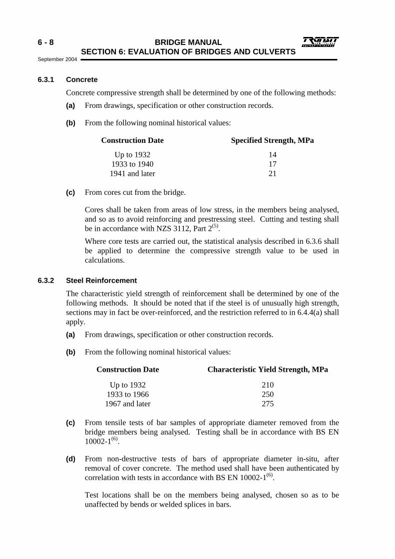
6.3.1 Concrete
Concrete compressive strength shall be determined by one of the following methods: (a) From drawings, specification or other construction records.
(b) From the following nominal historical values:
Construction Date Specified Strength, MPa
Up to 1932 14 1933 to 1940 17 1941 and later 21
(c) From cores cut from the bridge.
Cores shall be taken from areas of low stress, in the members being analysed, and so as to avoid reinforcing and prestressing steel. Cutting and testing shall be in accordance with NZS 3112, Part 2(5). Where core tests are carried out, the statistical analysis described in 6.3.6 shall be applied to determine the compressive strength value to be used in calculations.
6.3.2 Steel Reinforcement
The characteristic yield strength of reinforcement shall be determined by one of the following methods. It should be noted that if the steel is of unusually high strength, sections may in fact be over-reinforced, and the restriction referred to in 6.4.4(a) shall apply. (a) From drawings, specification or other construction records.
(b) From the following nominal historical values:
Construction Date Characteristic Yield Strength, MPa
Up to 1932 210 1933 to 1966 250 1967 and later 275
(c) From tensile tests of bar samples of appropriate diameter removed from the
bridge members being analysed. Testing shall be in accordance with BS EN 10002-1(6).
(d) From non-destructive tests of bars of appropriate diameter in-situ, after removal of cover concrete. The method used shall have been authenticated by correlation with tests in accordance with BS EN 10002-1(6).
Test locations shall be on the members being analysed, chosen so as to be unaffected by bends or welded splices in bars.
BRIDGE MANUAL 6 - 9 SECTION 6: EVALUATION OF BRIDGES AND CULVERTS
September 2004
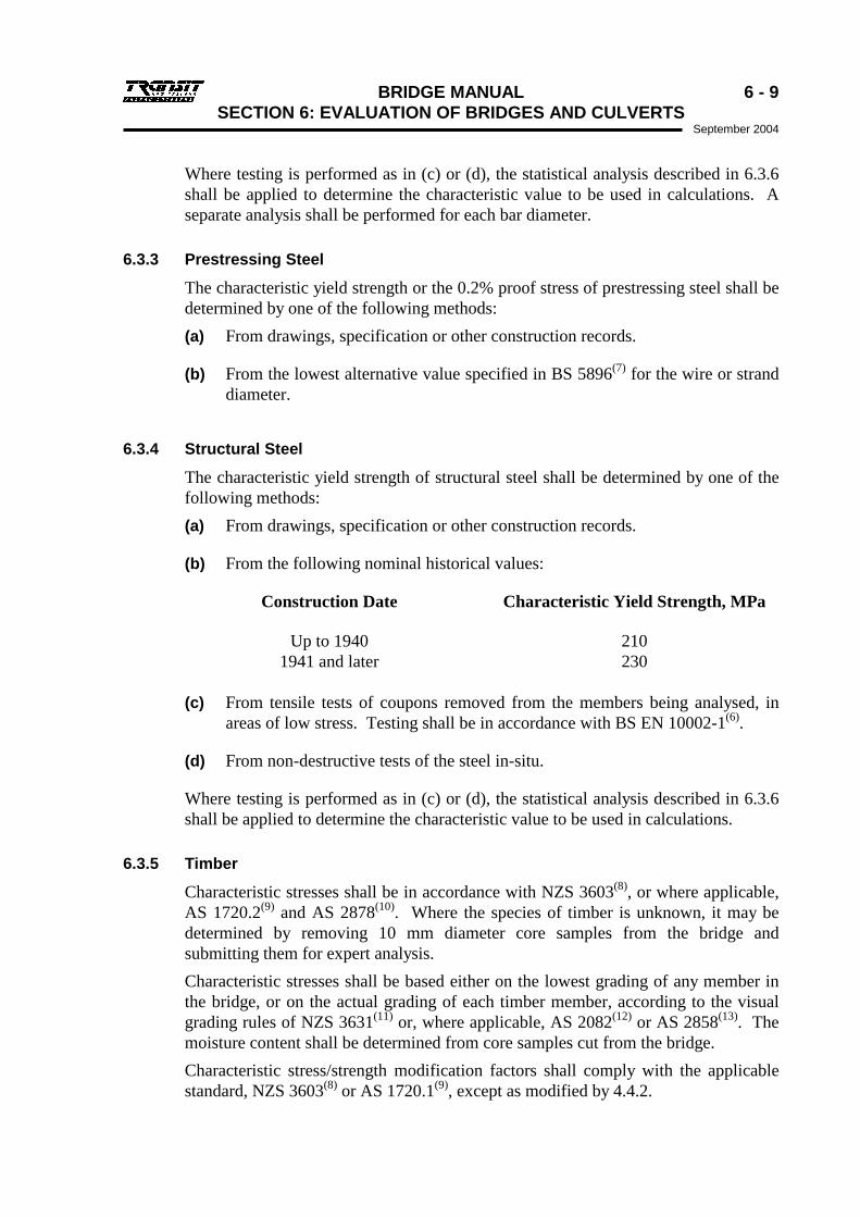
Where testing is performed as in (c) or (d), the statistical analysis described in 6.3.6 shall be applied to determine the characteristic value to be used in calculations. A separate analysis shall be performed for each bar diameter.
6.3.3 Prestressing Steel
The characteristic yield strength or the 0.2% proof stress of prestressing steel shall be determined by one of the following methods: (a) From drawings, specification or other construction records.
(b) From the lowest alternative value specified in BS 5896(7) for the wire or strand diameter.
6.3.4 Structural Steel
The characteristic yield strength of structural steel shall be determined by one of the following methods: (a) From drawings, specification or other construction records.
(b) From the following nominal historical values:
Construction Date Characteristic Yield Strength, MPa
Up to 1940 210 1941 and later 230
(c) From tensile tests of coupons removed from the members being analysed, in
areas of low stress. Testing shall be in accordance with BS EN 10002-1(6).
(d) From non-destructive tests of the steel in-situ.
Where testing is performed as in (c) or (d), the statistical analysis described in 6.3.6 shall be applied to determine the characteristic value to be used in calculations.
6.3.5 Timber
Characteristic stresses shall be in accordance with NZS 3603(8), or where applicable, AS 1720.2(9) and AS 2878(10). Where the species of timber is unknown, it may be determined by removing 10 mm diameter core samples from the bridge and submitting them for expert analysis. Characteristic stresses shall be based either on the lowest grading of any member in the bridge, or on the actual grading of each timber member, according to the visual grading rules of NZS 3631(11) or, where applicable, AS 2082(12) or AS 2858(13). The moisture content shall be determined from core samples cut from the bridge. Characteristic stress/strength modification factors shall comply with the applicable standard, NZS 3603(8) or AS 1720.1(9), except as modified by 4.4.2.
6 - 10 BRIDGE MANUAL SECTION 6: EVALUATION OF BRIDGES AND CULVERTS September 2004
Determination of design stresses for timber is discussed in Strength and Durability of Timber Bridges(14).
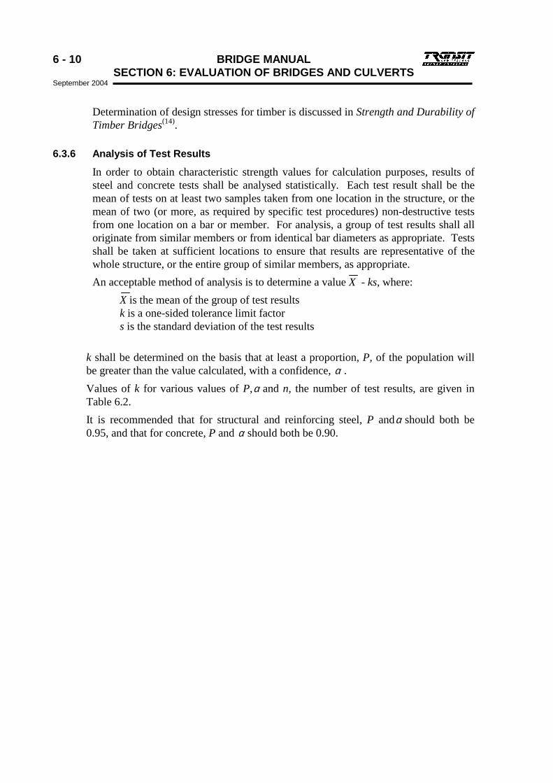
6.3.6 Analysis of Test Results
In order to obtain characteristic strength values for calculation purposes, results of steel and concrete tests shall be analysed statistically. Each test result shall be the mean of tests on at least two samples taken from one location in the structure, or the mean of two (or more, as required by specific test procedures) non-destructive tests from one location on a bar or member. For analysis, a group of test results shall all originate from similar members or from identical bar diameters as appropriate. Tests shall be taken at sufficient locations to ensure that results are representative of the whole structure, or the entire group of similar members, as appropriate. An acceptable method of analysis is to determine a value X - ks, where:
X is the mean of the group of test results k is a one-sided tolerance limit factor s is the standard deviation of the test results
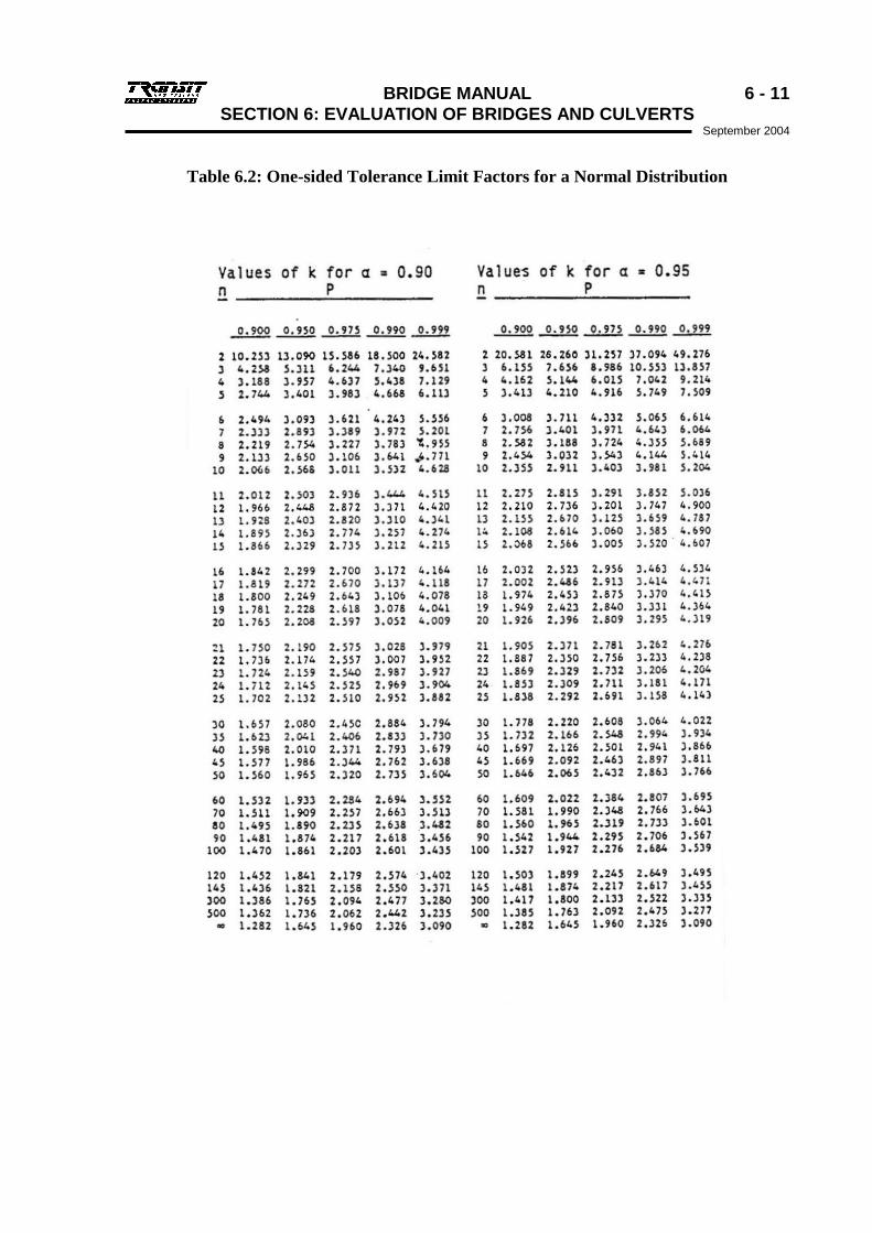
k shall be determined on the basis that at least a proportion, P, of the population will be greater than the value calculated, with a confidence, α . Values of k for various values of P,α and n, the number of test results, are given in Table 6.2. It is recommended that for structural and reinforcing steel, P andα should both be 0.95, and that for concrete, P and α should both be 0.90.
BRIDGE MANUAL 6 - 11 SECTION 6: EVALUATION OF BRIDGES AND CULVERTS
September 2004
Table 6.2: One-sided Tolerance Limit Factors for a Normal Distribution
6 - 12 BRIDGE MANUAL SECTION 6: EVALUATION OF BRIDGES AND CULVERTS September 2004
6.4 Main Member Capacity and Evaluation
6.4.1 General
The bridge Overload and/or Live Load Capacity shall be determined in terms of the net unfactored service load at the critical section of any member or group of identical members which could be critical under any live loading. The capacity of a member may be in any terms - i.e., moment, shear, torsion, direct force, bearing, or an interaction relationship between any of these. Assumptions which may be made about the behaviour of specific structures in defined circumstances are set out in 6.4.4.
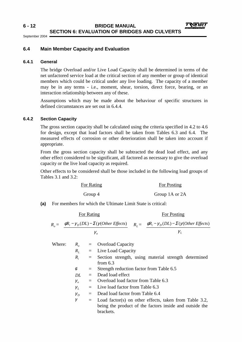
6.4.2 Section Capacity
The gross section capacity shall be calculated using the criteria specified in 4.2 to 4.6 for design, except that load factors shall be taken from Tables 6.3 and 6.4. The measured effects of corrosion or other deterioration shall be taken into account if appropriate. From the gross section capacity shall be subtracted the dead load effect, and any other effect considered to be significant, all factored as necessary to give the overload capacity or the live load capacity as required. Other effects to be considered shall be those included in the following load groups of Tables 3.1 and 3.2:
For Rating For Posting
Group 4 Group 1A or 2A
(a) For members for which the Ultimate Limit State is critical:
For Rating For Posting
oR = )(()( ctsOther EffeDLR Di γγφ Σ−− LR = )(()( ctsOther EffeDLR Di γγφ Σ−−
oγ Lγ
Where: oR = Overload Capacity LR = Live Load Capacity iR = Section strength, using material strength determined
from 6.3 φ = Strength reduction factor from Table 6.5 DL = Dead load effect oγ = Overload load factor from Table 6.3 Lγ = Live load factor from Table 6.3 Dγ = Dead load factor from Table 6.4 γ = Load factor(s) on other effects, taken from Table 3.2,
being the product of the factors inside and outside the brackets.
BRIDGE MANUAL 6 - 13 SECTION 6: EVALUATION OF BRIDGES AND CULVERTS
September 2004
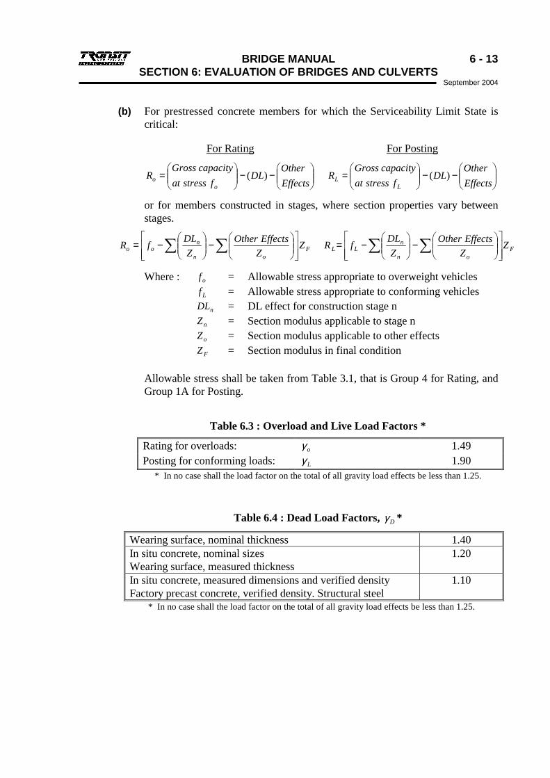
(b) For prestressed concrete members for which the Serviceability Limit State is critical:
For Rating For Posting
−−
=
EffectsOther
DLfstressat
capacityGrossR
oo )(
−−
=
EffectsOther
DLfstressat
capacityGrossR
LL )(
or for members constructed in stages, where section properties vary between stages.
Fon
noo Z
ZEffectsOther
ZDLfR
−
−= ∑∑ F
on
nLL Z
ZEffectsOther
ZDLfR
−
−= ∑∑
Where : of = Allowable stress appropriate to overweight vehicles Lf = Allowable stress appropriate to conforming vehicles nDL = DL effect for construction stage n nZ = Section modulus applicable to stage n oZ = Section modulus applicable to other effects FZ = Section modulus in final condition
Allowable stress shall be taken from Table 3.1, that is Group 4 for Rating, and Group 1A for Posting.
Table 6.3 : Overload and Live Load Factors *
Rating for overloads: oγ 1.49 Posting for conforming loads: Lγ 1.90
* In no case shall the load factor on the total of all gravity load effects be less than 1.25.
Table 6.4 : Dead Load Factors, Dγ *
Wearing surface, nominal thickness 1.40 In situ concrete, nominal sizes Wearing surface, measured thickness
1.20
In situ concrete, measured dimensions and verified density Factory precast concrete, verified density. Structural steel
1.10
* In no case shall the load factor on the total of all gravity load effects be less than 1.25.
6 - 14 BRIDGE MANUAL SECTION 6: EVALUATION OF BRIDGES AND CULVERTS September 2004
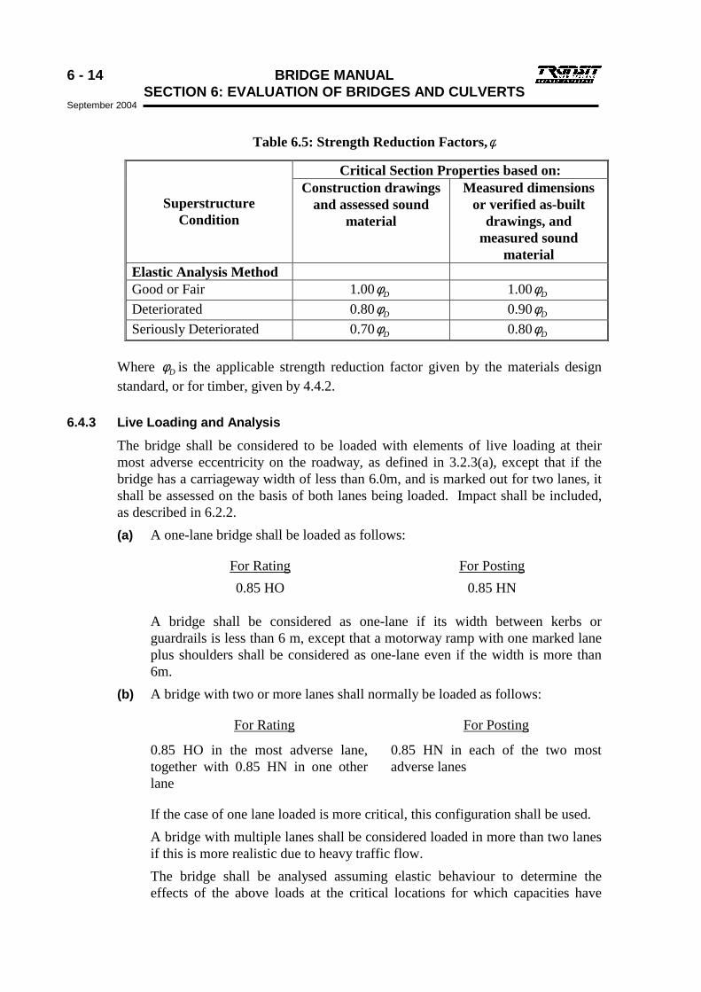
Table 6.5: Strength Reduction Factors,φ
Critical Section Properties based on:
Superstructure Condition
Construction drawings and assessed sound
material
Measured dimensions or verified as-built
drawings, and measured sound
material Elastic Analysis Method Good or Fair 1.00 Dφ 1.00 Dφ Deteriorated 0.80 Dφ 0.90 Dφ Seriously Deteriorated 0.70 Dφ 0.80 Dφ
Where Dφ is the applicable strength reduction factor given by the materials design standard, or for timber, given by 4.4.2.
6.4.3 Live Loading and Analysis
The bridge shall be considered to be loaded with elements of live loading at their most adverse eccentricity on the roadway, as defined in 3.2.3(a), except that if the bridge has a carriageway width of less than 6.0m, and is marked out for two lanes, it shall be assessed on the basis of both lanes being loaded. Impact shall be included, as described in 6.2.2. (a) A one-lane bridge shall be loaded as follows:
For Rating For Posting 0.85 HO 0.85 HN
A bridge shall be considered as one-lane if its width between kerbs or guardrails is less than 6 m, except that a motorway ramp with one marked lane plus shoulders shall be considered as one-lane even if the width is more than 6m.
(b) A bridge with two or more lanes shall normally be loaded as follows:
For Rating For Posting
0.85 HO in the most adverse lane, together with 0.85 HN in one other lane
0.85 HN in each of the two most adverse lanes
If the case of one lane loaded is more critical, this configuration shall be used. A bridge with multiple lanes shall be considered loaded in more than two lanes if this is more realistic due to heavy traffic flow. The bridge shall be analysed assuming elastic behaviour to determine the effects of the above loads at the critical locations for which capacities have
BRIDGE MANUAL 6 - 15 SECTION 6: EVALUATION OF BRIDGES AND CULVERTS
September 2004
been determined. Analysis shall take into consideration the relative stiffnesses of the various members, and their end conditions. Stiffness values for reinforced concrete members shall allow for the effects of cracking.
6.4.4 Assumptions for Specific Structural Situations (a) Over-reinforced Concrete Sections
The intent of Clause 8.4.2 of NZS 3101(15) shall be complied with. The capacity of a reinforced concrete section shall not be taken as more than that derived using the area of tension steel which would correspond to a distance from the extreme compression fibre to the neutral axis of 0.75 bC .
bC is the distance from extreme compression fibre to neutral axis at balanced strain conditions, as defined in 8.4.1.2 of NZS 3101(15).
(b) Concrete Kerbs Cast onto a Composite Deck Where a kerb has been cast directly onto the deck over its full length, and has at least a nominal amount of reinforcing steel connecting it to the deck, and is within the effective flange width of the beam, the moment capacity of the outer beam may be calculated assuming that the kerb is an integral part of it, with the following provisos:
• The area of concrete in the kerb shall be assumed to be 50% of its actual area, to allow for shear lag effects, unless tests indicate otherwise.
• The neutral axis shall not be taken to be above the level of the deck surface.
(c) Concrete Handrails No reliance shall be placed on the contribution to longitudinal bending capacity of beams by concrete handrails.
(d) Steel Beams with Non-Composite Concrete Deck No account shall be taken of such a non-composite deck in determining the bending capacity of the beams, except insofar as it may stiffen the beam top flanges, and thus increase their buckling load. Friction shall not be considered to contribute to composite action, nor to the stiffening of top flanges.
(e) Steel Beams with Timber Deck Effective lateral support of the beam flanges by the deck shall only be assumed if the timber deck fastenings are adequate in number and condition.
(f) Continuous or Framed-in Beams For beams with full moment continuity between spans, of normal proportions and showing no signs of distress, the following simplified procedure may be followed. The overall moment capacity of each span may be converted to that of an equivalent simple span by subtracting (algebraically) the midspan positive moment capacity from the mean of the two negative moment capacities at its supports. This will give the overall ordinate of the moment of resistance diagram, and both dead and live load moments may then be calculated as

6 - 16 BRIDGE MANUAL SECTION 6: EVALUATION OF BRIDGES AND CULVERTS September 2004
though it were a simple span. This procedure shall not be followed for a short span whose length is less than 60% of an adjacent long span, nor for live load effect on a span adjacent to a free cantilever span. The possibility of uplift at an adjacent support shall be considered.
(g) Spans Built Into Abutments Reinforced concrete T-beam spans built monolithically with their abutments may be considered for treatment as in (f), with the following provisos: (i) if negative moment yield at abutments can be shown to occur at a load
greater than 85% of that at which midspan positive moment yield occurs, the working load capacity may be based on the full yield capacity of the section at all locations;
(ii) if negative moment yield at abutments occurs at a lesser load than 85% of that at which midspan positive moment yield occurs,
Either: the net unfactored service load capacity may be based on the full yield capacity at the abutments, with a reduced yield capacity at midspan, corresponding to the actual moment when abutment yield occurs,
or: the net unfactored service load capacity may be calculated assuming zero abutment moment capacity.
In any case, where negative moment capacity is to be relied on, the ability of the abutments to resist the overall negative moments, without excessive displacement, either by foundation reaction or by earth pressure, or both, shall be assured.
(h) Horizontal Support Restraint Where the bearings and supports of a beam possess sufficient strength and stiffness horizontally, the horizontal support reaction to live loading may be taken into account where appropriate.
BRIDGE MANUAL 6 - 17 SECTION 6: EVALUATION OF BRIDGES AND CULVERTS
September 2004
6.4.5 Evaluation
For each critical location in the bridge, the evaluation percentage shall be calculated as described below. In both calculations, the denominator shall include the effects of eccentricity of load and of impact. oR and LR are the section capacities calculated as 6.4.2. If data is to be entered into the Highway Permits system, the CLASS calculation is not necessary. See 6.4.6.
For Rating For Posting
%100
min
=
effectloadRatingxRCLASS o %100
min
=
effectloadPostingxRGROSS L
The minimum value for any member in the bridge except the deck, shall be recorded in a structural inventory as the CLASS for manual calculations during processing of overweight permits in accordance with the Overweight Permit Manual(1). For this purpose, any value of CLASS more than 120% shall be recorded as 120%.
The minimum value for any member in the bridge except the deck, shall be rounded to the nearest 10%. If this value is less than 100%, it shall be recorded after the word GROSS in Panel 2 of the Heavy Motor Vehicle Bridge Limit Sign, shown in Diagram 4 of the 4th Schedule of the Heavy Motor Vehicle Regulations(2).
If the speed is restricted by inserting a value in Panel 3 of the sign, the impact factor used in the calculation may be reduced as follows:
Speed Impact Factor 30 km/h
10 km/h (I - 1) x 0.67 + 1 (I - 1) x 0.33 + 1
Where I is the Impact Factor appropriate for unrestricted heavy traffic.
6.4.6 Highway Permits Data
In the particular case of State Highway bridges, and some bypass routes, the basic Rating data described above is stored in the Highway Permits system database. A description of the form in which the data is required, and the calculations which the program performs, is contained in Highway Permits Assurance Manual(3).
6.5 Deck Capacity and Evaluation
6.5.1 General
The following three procedures are given in this clause: ••••
Reinforced concrete decks by empirical method, based on assumed membrane action
6 - 18 BRIDGE MANUAL SECTION 6: EVALUATION OF BRIDGES AND CULVERTS September 2004
••••
Reinforced concrete decks by elastic plate bending analysis
••••
Timber decks.
Generally, a reinforced concrete deck panel which is supported on four sides should be evaluated by the empirical method if it meets the criteria listed in 6.5.2(a). All other reinforced concrete deck panels should be evaluated by the elastic plate bending analysis method. In addition, reinforced concrete deck slabs shall be evaluated for their punching shear capacity for wheel loads, taking into account deterioration of the bridge deck using the factors in Table 6.5. It shall be assumed that vehicle wheels can be transversely positioned anywhere between the kerbs or guardrails, but not closer to them than the restriction imposed by the 3m wide load lane of HN-HO-72 loading (Figure 3.1).
6.5.2 Reinforced Concrete Decks: Empirical Evaluation Method (a) Criteria for Determining Applicability of the Empirical Method
The empirical method takes account of membrane action in the slab, and is based on test results. Evaluation of both composite and non-composite reinforced concrete deck slab panels may be determined by this method provided the following conditions are satisfied:
• the supporting beams or girders shall be steel or concrete,
• cross frames or diaphragms shall be continuous between external beams or girders, and the maximum spacing of such cross frames or diaphragms shall be as follows:
Steel I beams and Box Girders of steel or concrete: 8.0 m Reinforced and prestressed concrete beams: at supports
• the ratio of span length ( sL ) to minimum slab thickness shall not exceed 20. In skew slabs where the reinforcing has been placed parallel with the skew, the skew span, CosLs / Υ shall be used, where Υ = angle of skew.
• the span length ( sL ) or CosLs / Υ shall not exceed 4.5 m,
• the concrete compressive strength shall not be less than 20 MPa,
• the slab thickness, or for slabs of variable thickness the minimum slab thickness, shall be not less than 150 mm.
• there shall be an overhang beyond the centreline of the outside beam of at least 0.80 m, measured perpendicular to the beam. The overhang shall be of the minimum slab thickness used to determine the span to thickness ratio above. This condition may be considered satisfied if there is an integral continuous concrete kerb or barrier which provides a combined cross sectional area of slab and kerb or barrier not less than the cross sectional area of 0.80 m of deck slab.
BRIDGE MANUAL 6 - 19 SECTION 6: EVALUATION OF BRIDGES AND CULVERTS
September 2004
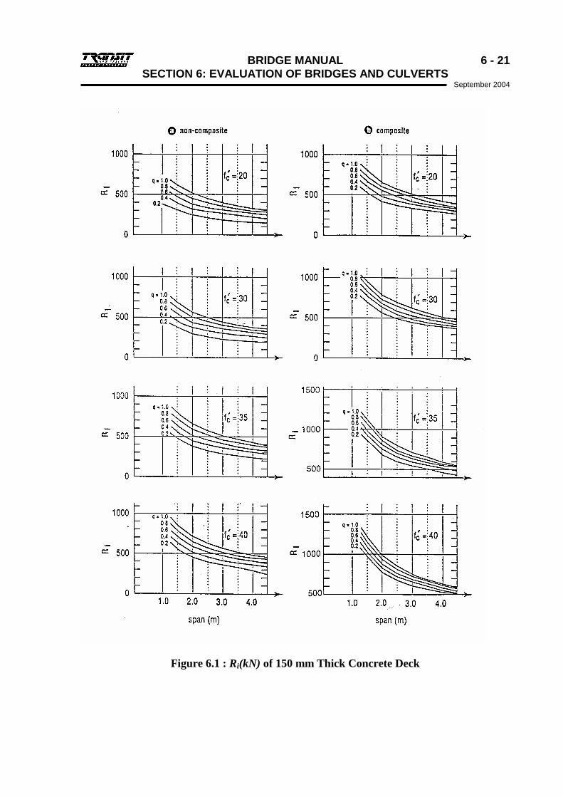
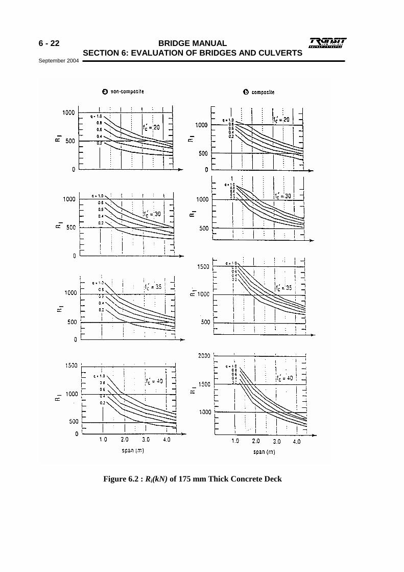
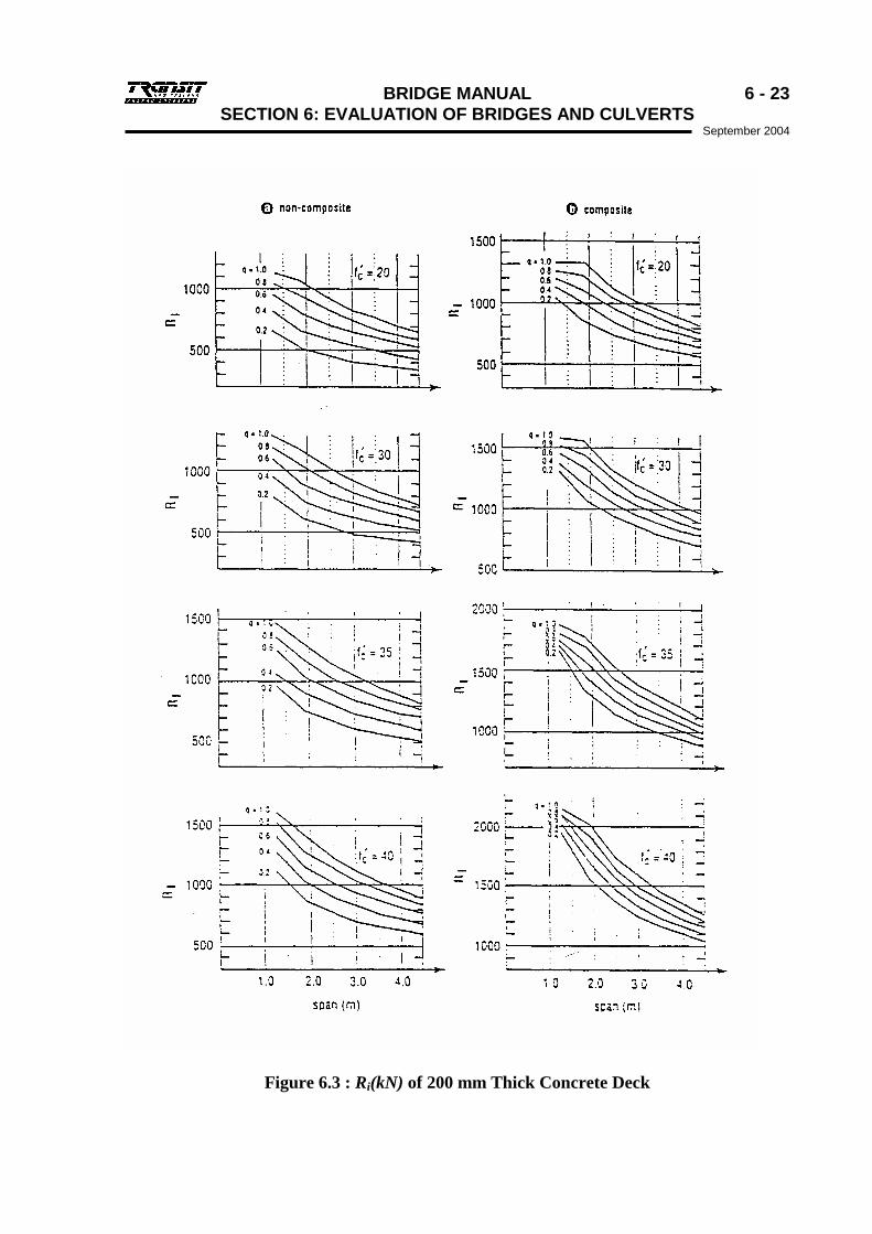
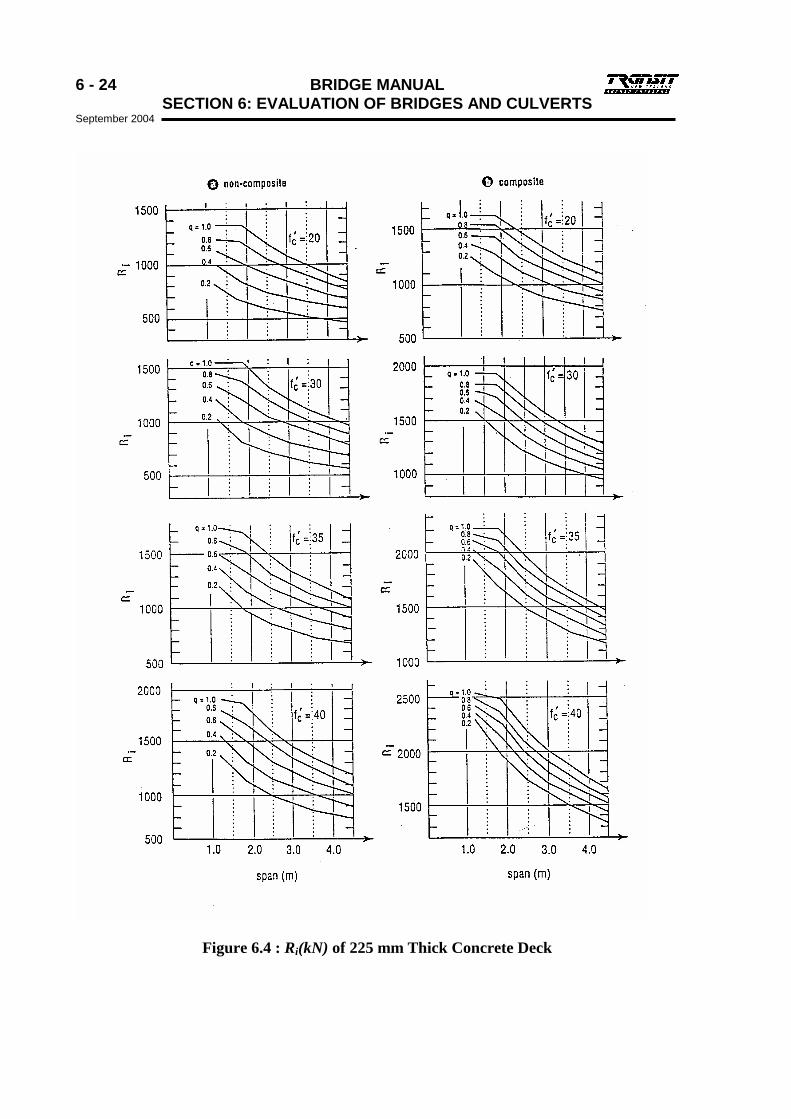
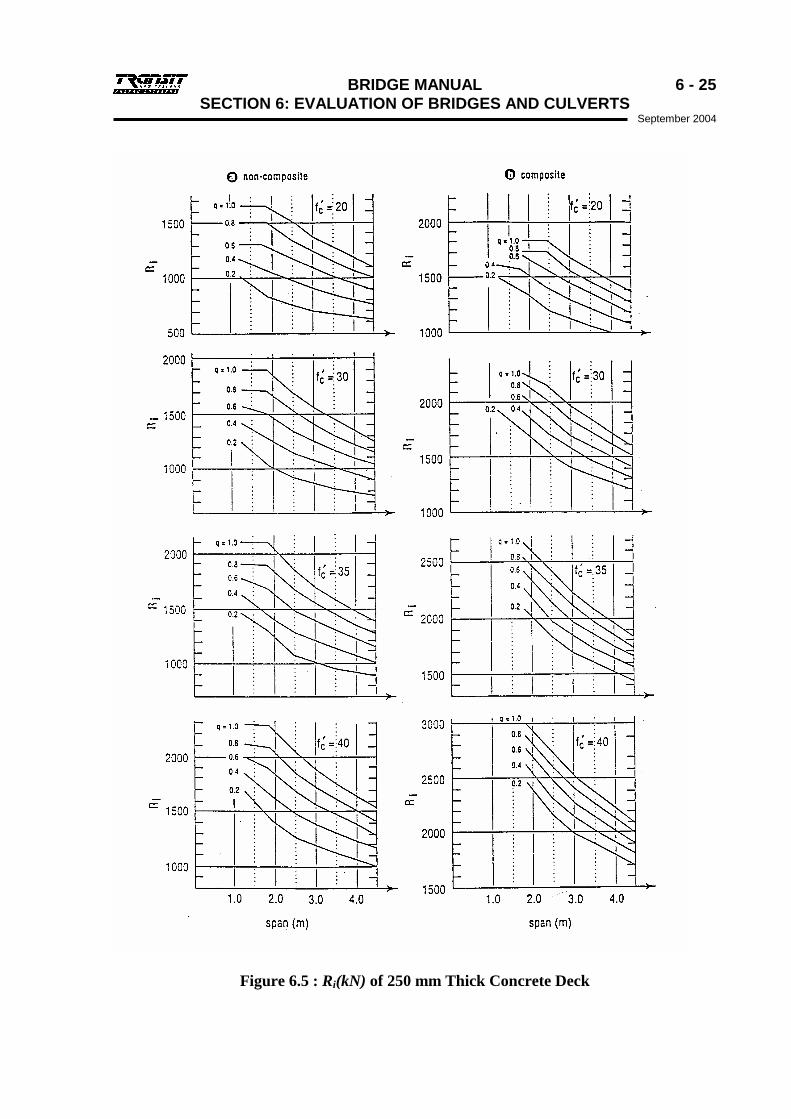
(b) Deck Strength in Terms of Wheel Load For rating (HO wheel contact area Alternative (b) of Figure 3.1 assumed), the unfactored ultimate resistance, iR , of a composite or non-composite deck slab shall be obtained from Figures 6.1 to 6.5. For posting (HN wheel contact area assumed), the value from the charts shall be multiplied by 0.6. The value of reinforcement percentage, q, used to determine iR shall be the average of the lower layer reinforcement percentages at the mid span of the slab, in the two directions in which the reinforcement is placed. Values of iR for slab depths or concrete strengths intermediate between those on the charts shall be obtained by interpolation. The dead load and other load effects are ignored in this method. The strength reduction factor, Dφ , for design by the empirical method is 0.5. The strength reduction factor, φ , used for evaluation shall be taken from Table 6.6, by multiplying Dφ by the appropriate factor. In this table, deck deterioration is quantified by the Crack-to-Reinforcing Ratio, CRR, defined as follows: CRR= Total length of visible cracks x 100 Total length of bottom reinforcement in both directions
The above lengths shall be measured in a 1.2 m square area on the bottom of the slab, central between supports.
Table 6.6: Strength Reduction Factors, φ for Slabs Evaluated by the Empirical Method
Slab Section Properties based on:
Superstructure Condition
Construction drawings and assessed sound
material
Measured dimensions or verified as-built
drawings, and measured sound
material Good or Fair
(CRR ≤ 40%) 0.90 Dφ 1.00 Dφ
Deteriorated (CRR = 70%)
0.60 Dφ 0.70 Dφ
Seriously Deteriorated (CRR = 100%)
0.30 Dφ 0.40 Dφ
6 - 20 BRIDGE MANUAL SECTION 6: EVALUATION OF BRIDGES AND CULVERTS September 2004
(c) Evaluation For each type of slab panel in the bridge, the parameters shall be calculated as follows. Rating and posting wheel loads shall be taken from Tables 6.7 and 6.8. Impact factor, I, shall be as described in 6.2.2. oγ and Lγ shall be taken from Table 6.3.
For Rating For Posting
Deck Capacity Factor (DCF) Allowable Axle Load (kg)
min
=
effectloadRatingcapacityloadwheelOverload
min
8200
= x
effectloadPostingcapacityloadwheelLiveload
min95
=
IxxR
o
i
γφ
min
820040
)6.0(
= x
IxxRx
L
i
γφ
BRIDGE MANUAL 6 - 21 SECTION 6: EVALUATION OF BRIDGES AND CULVERTS
September 2004
Figure 6.1 : Ri(kN) of 150 mm Thick Concrete Deck
6 - 22 BRIDGE MANUAL SECTION 6: EVALUATION OF BRIDGES AND CULVERTS September 2004
Figure 6.2 : Ri(kN) of 175 mm Thick Concrete Deck
BRIDGE MANUAL 6 - 23 SECTION 6: EVALUATION OF BRIDGES AND CULVERTS
September 2004
Figure 6.3 : Ri(kN) of 200 mm Thick Concrete Deck
6 - 24 BRIDGE MANUAL SECTION 6: EVALUATION OF BRIDGES AND CULVERTS September 2004
Figure 6.4 : Ri(kN) of 225 mm Thick Concrete Deck
BRIDGE MANUAL 6 - 25 SECTION 6: EVALUATION OF BRIDGES AND CULVERTS
September 2004
Figure 6.5 : Ri(kN) of 250 mm Thick Concrete Deck
6 - 26 BRIDGE MANUAL SECTION 6: EVALUATION OF BRIDGES AND CULVERTS September 2004
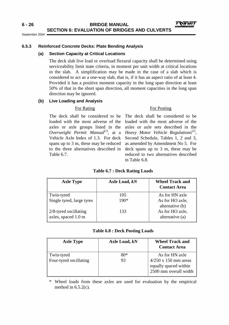
6.5.3 Reinforced Concrete Decks: Plate Bending Analysis (a) Section Capacity at Critical Locations
The deck slab live load or overload flexural capacity shall be determined using serviceability limit state criteria, in moment per unit width at critical locations in the slab. A simplification may be made in the case of a slab which is considered to act as a one-way slab, that is, if it has an aspect ratio of at least 4. Provided it has a positive moment capacity in the long span direction at least 50% of that in the short span direction, all moment capacities in the long span direction may be ignored.
(b) Live Loading and Analysis For Rating For Posting
The deck shall be considered to be loaded with the most adverse of the axles or axle groups listed in the Overweight Permit Manual(1), at a Vehicle Axle Index of 1.3. For deck spans up to 3 m, these may be reduced to the three alternatives described in Table 6.7.
The deck shall be considered to be loaded with the most adverse of the axles or axle sets described in the Heavy Motor Vehicle Regulations(2), Second Schedule, Tables 1, 2 and 3, as amended by Amendment No 5. For deck spans up to 3 m, these may be reduced to two alternatives described in Table 6.8.
Table 6.7 : Deck Rating Loads
Axle Type Axle Load, kN Wheel Track and Contact Area
Twin-tyred 105 As for HN axle Single tyred, large tyres 190* As for HO axle,
alternative (b) 2/8-tyred oscillating axles, spaced 1.0 m
133 As for HO axle, alternative (a)
Table 6.8 : Deck Posting Loads
Axle Type Axle Load, kN Wheel Track and Contact Area
Twin-tyred 80* As for HN axle Four-tyred oscillating 93 4/250 x 150 mm areas
equally spaced within 2500 mm overall width
* Wheel loads from these axles are used for evaluation by the empirical method in 6.5.2(c).
BRIDGE MANUAL 6 - 27 SECTION 6: EVALUATION OF BRIDGES AND CULVERTS
September 2004
The slab shall be analysed for the loads given in Tables 6.7 and/or 6.8 assuming elastic behaviour, and shall be assumed to act as a thin plate in which membrane action is not taken into account. The moment effects of the various loads on the critical locations shall be calculated.
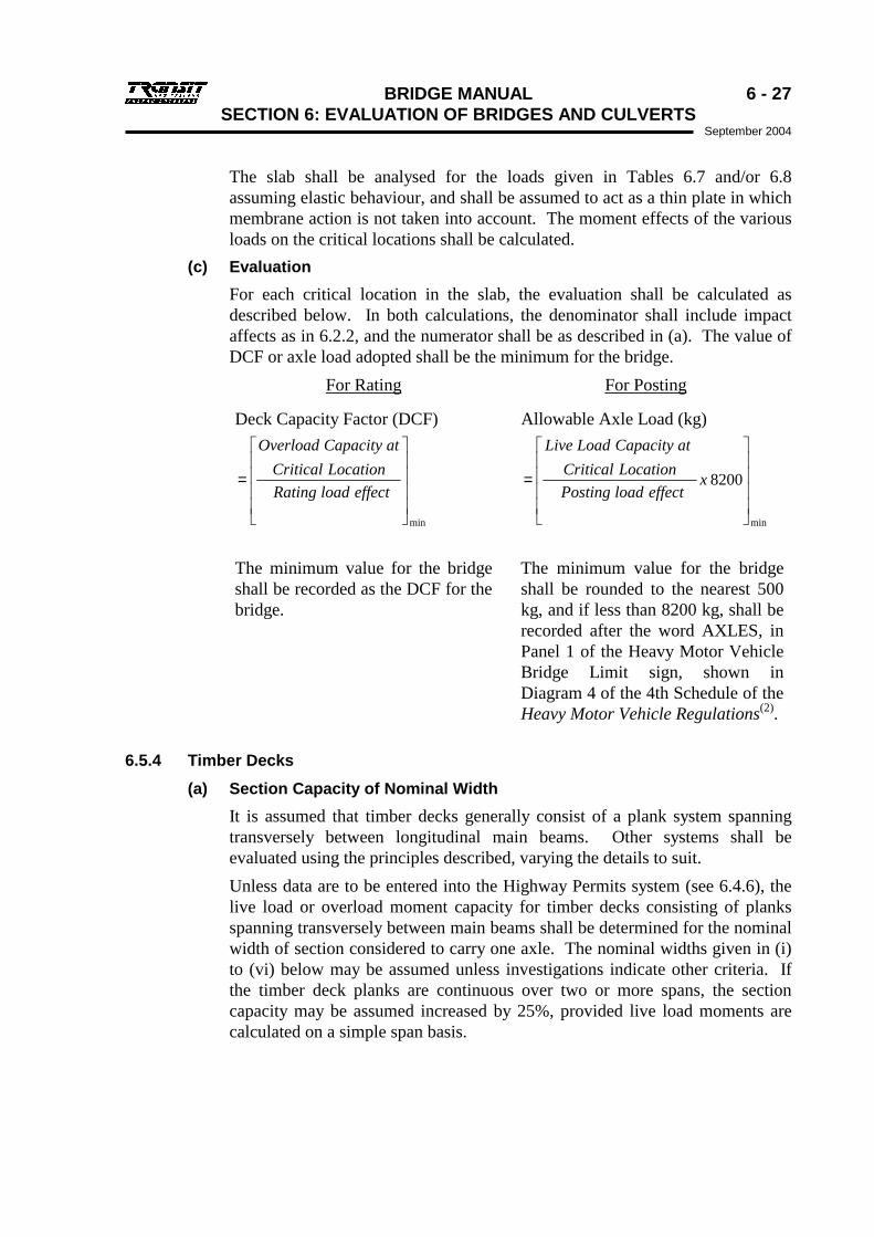
(c) Evaluation For each critical location in the slab, the evaluation shall be calculated as described below. In both calculations, the denominator shall include impact affects as in 6.2.2, and the numerator shall be as described in (a). The value of DCF or axle load adopted shall be the minimum for the bridge.
For Rating For Posting
Deck Capacity Factor (DCF) Allowable Axle Load (kg)
min
=effectloadRating
LocationCriticalatCapacityOverload
min
8200
= xeffectloadPosting
LocationCriticalatCapacityLoadLive
The minimum value for the bridge shall be recorded as the DCF for the bridge.
The minimum value for the bridge shall be rounded to the nearest 500 kg, and if less than 8200 kg, shall be recorded after the word AXLES, in Panel 1 of the Heavy Motor Vehicle Bridge Limit sign, shown in Diagram 4 of the 4th Schedule of the Heavy Motor Vehicle Regulations(2).
6.5.4 Timber Decks (a) Section Capacity of Nominal Width
It is assumed that timber decks generally consist of a plank system spanning transversely between longitudinal main beams. Other systems shall be evaluated using the principles described, varying the details to suit. Unless data are to be entered into the Highway Permits system (see 6.4.6), the live load or overload moment capacity for timber decks consisting of planks spanning transversely between main beams shall be determined for the nominal width of section considered to carry one axle. The nominal widths given in (i) to (vi) below may be assumed unless investigations indicate other criteria. If the timber deck planks are continuous over two or more spans, the section capacity may be assumed increased by 25%, provided live load moments are calculated on a simple span basis.

6 - 28 BRIDGE MANUAL SECTION 6: EVALUATION OF BRIDGES AND CULVERTS September 2004
Terms are defined as follows: Plank Width is the larger cross sectional dimension of a deck plank,
regardless of its orientation, in metres. It is the actual dimension, not the call dimension.
Deck Span is the span of the planks between the centres of areas of bearing, in metres.
Contact Length is the dimension, perpendicular to the plank span, of a wheel contact area, and is assumed to be 0.250 m.
Nominal Width (i) For planks laid flat, without running planks at least 50 mm thick, the
nominal width is equal to the width of a whole number of planks, and is greater than the contact length by not more than one plank width.
(i) For planks laid flat, with running planks at least 50 mm thick, the nominal width is equal to the width of a whole number of planks, and is greater than the contact length by not more than two plank widths.
(ii) For nail laminated deck, with planks on edge, fabricated into baulks with no shear connection between them, the nominal width is:
0.250 m + 0.4 x (Plank width) x (Deck span). (iii) For nail laminated deck, with planks on edge, end laminations well
supported and:
• either fabricated in baulks with shear connection between them by steel dowels or other means; or
• fabricated in baulks and having running planks over them more than 50 mm thick; or
• fabricated in-situ, continuously across the beam span, with no unconnected joints between laminations, the nominal width is:
0.250 m + 0.8 x (Plank width) x (Deck span)
(iv) For glue laminated deck, with planks on edge, fabricated in baulks with no shear connection between them, the nominal width is:
0.250 m + 1.5 x (Plank width) x (Deck span) (v) For glue laminated deck, with planks on edge, otherwise as for (iv), the
nominal width is:
0.250 m + 3.0 x (Plank width) x (Deck span) Dead load may be neglected in the above calculation.
(b) Live Loading and Analysis The transverse moments due to the various axles described in Tables 6.7 and/or 6.8 on the span between beams shall be calculated assuming the deck planks are simply supported.
BRIDGE MANUAL 6 - 29 SECTION 6: EVALUATION OF BRIDGES AND CULVERTS
September 2004
(c) Evaluation For the nominal width at the mid-span section of a timber deck span, the evaluation shall be calculated as described below. In both calculations, the numerator shall be as described in (a). The value of DCF or axial load adopted shall be the minimum for the bridge.
For Rating For Posting
Deck Capacity Factor (DCF) Allowable Axle Load (kg)
mineffect load Rating WidthNominal ofCapacity Overload
=
min
8200effect load Posting
WidthNominal ofCapacity Load Live
= x
The minimum value for the bridge shall be recorded as the DCF for the bridge.
The minimum value for the bridge shall be rounded to the nearest 500 kg, and if less than 8200 kg, shall be recorded after the word AXLES, in Panel 1 of the Heavy Motor Vehicle Bridge Limit sign, shown in Diagram 4 of the 4th Schedule of the Heavy Motor Vehicle Regulations(2).
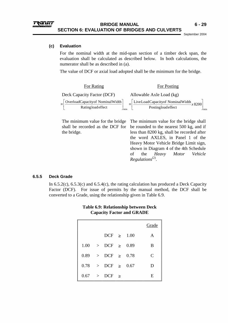
6.5.5 Deck Grade
In 6.5.2(c), 6.5.3(c) and 6.5.4(c), the rating calculation has produced a Deck Capacity Factor (DCF). For issue of permits by the manual method, the DCF shall be converted to a Grade, using the relationship given in Table 6.9.
Table 6.9: Relationship between Deck Capacity Factor and GRADE
Grade
DCF ≥ 1.00 A
1.00 > DCF ≥ 0.89 B
0.89 > DCF ≥ 0.78 C
0.78 > DCF ≥ 0.67 D
0.67 > DCF ≥ E
6 - 30 BRIDGE MANUAL SECTION 6: EVALUATION OF BRIDGES AND CULVERTS September 2004
6.5.6 Highway Permits Data
The statement in 6.4.6 applies but, for decks, the Deck Capacity Factor is required in addition to the moment capacity and geometric data.
6.6 Proof Loading Proof loading may be undertaken in addition to the procedure described in 6.1 to 6.5, either to verify the theoretical findings and assumptions made, or to extend the load limits where the results of the procedure are considered to be not representative of the structure's actual behaviour. Proof loading shall not be relied on to determine load limits for bridges with features such as those described in 6.6.2(a)(vi) and (v), without either modifying the structure, or multiplying the load factors of 6.4.2 by 1.5.
6.6.1 Preliminary (a) Objective
The objective of proof loading shall be to determine experimentally the safe load limit for either overweight loads or normal loads or both, expressed as defined in 6.4.5, 6.5.2(c), 6.5.3(c) and 6.5.4(c).
(b) Scope These requirements apply to main member spans of all materials up to 30 m, and to decks. Proof loading of spans larger than 30 m may require additional criteria.
(c) Analysis Before testing of any bridge, adequate analysis shall be performed to determine its likely behaviour, including its failure mode.
(d) Personnel Personnel engaged in proof loading shall be experienced and competent, in order to minimise the risk associated with loading beyond the linear range.
(e) Risk The risk of failure or damage being induced by testing shall be clearly stated to the controlling authority.
6.6.2 Analysis (a) Objectives
The objectives of the analysis shall be: (i) To model the structural behaviour up to yield level.
(ii) To assess the amount of redundancy in the structural system, and its implications for behaviour.
(iii) To determine if the bridge failure mode is likely to be ductile or not.
BRIDGE MANUAL 6 - 31 SECTION 6: EVALUATION OF BRIDGES AND CULVERTS
September 2004
(iv) To identify and evaluate features which would give an apparent enhancement of strength up to proof load level, but which could be followed by sudden failure. Such features may include a non-composite deck as described in 6.4.4(d).
(v) To identify and evaluate features which are likely to affect the distribution of loads differently at proof load level and at yield load level, such as a stiff concrete handrail, as described in 6.4.4(c).
(b) Evaluation of Main Members The bridge shall be analysed for the rating and/or posting load as described in 6.4.3, to determine the load effects at the critical location. It shall also be analysed for the actual test loading configuration proposed to be used. This shall be chosen so that it will produce approximately the same relative effects on critical members as the evaluation loading described in 6.4.3. If there is more than one critical effect to be monitored, the load may need to be applied in more than one place, e.g., to induce both maximum moment and shear in a beam.
(c) Evaluation of Decks Sufficient analysis shall be carried out to determine which of the axle configurations in Table 6.7 or 6.8 is most critical, and the critical load position(s). The likely failure mode(s) shall be determined.
6.6.3 Load Application, Instrumentation and Procedure
(a) The nature and magnitude of the proof load, and/or any prior modification of the structure, shall be consistent with the objectives of 6.6.2 (a).
(b) For evaluation of main members lanes shall be loaded to represent the effects of the evaluation loads described in 6.4.3, including impact factors as in 6.2.2.
For evaluation of decks, contact areas corresponding to the most critical of the axle loads of Tables 6.7 or 6.8 shall be loaded, to represent the evaluation load including impact.
(c) If the failure mode is likely to be non-ductile or there is little redundancy in the structure, a jacking system shall be used to apply the load in preference to gravity because of the added control it gives against inadvertent failure.
(d) Appropriate strains, deflections and crack widths shall be recorded, and correlated with the applied load. Care shall be taken to eliminate errors due to thermal movement. A plot of critical effect(s) against load, shall be monitored, to ensure that the limits set in 6.6.4 are not exceeded. The test load shall be applied in approximately equal increments, at least four of which shall lie on the anticipated linear part of the response curve. Critical effects shall be recorded in a consistent manner, immediately after the application of each load increment.
6 - 32 BRIDGE MANUAL SECTION 6: EVALUATION OF BRIDGES AND CULVERTS September 2004
(e) During incremental loading, the next increment of load shall not be applied until displacement under the previous increment of load has stabilised. Following application of the final increment of load the total proof load shall be applied for not less than fifteen minutes after the displacement has stabilised.
6.6.4 Load Limit Criteria (a) Main Members
Loading shall not exceed either: (i) the load which, together with dead load effects, produces 80% of the
yield load on the critical member, as determined by the analysis of 6.6.2.
(ii) that at which the response of the critical member deflection exceeds the value which would be predicted by linear extrapolation of the initial part of the load/response curve by the following percentage:
Member Material % Offset Structural Steel 10 Prestressed Concrete 15 Reinforced concrete, composite steel/concrete
20
Timber 25
(b) Decks
Loading shall not exceed either: (i) 80% of the load (on the same contact area) calculated to produce yield
in the deck.
(ii) that at which the deck local deflection exceeds a value determined as in (a)(ii) above.
(c) Concrete Cracking Criteria
At the maximum load, critical crack widths of reinforced concrete and prestressed concrete shall be recorded. If such cracks either: (i) are wider than allowed under Category IV of Table 3.4 in NZS 3101(15);
or
(ii) in reinforced concrete, do not close to less than one-third of the values in (i) after load removal; or
(iii) in prestressed concrete, do not close completely after load removal;
BRIDGE MANUAL 6 - 33 SECTION 6: EVALUATION OF BRIDGES AND CULVERTS
September 2004
then regular inspection shall be instituted, specifically to detect possible corrosion.
6.6.5 Evaluation (a) Correlation of Analysis and Test Results
The results of testing shall be compared with predicted results from the analysis of 6.6.2. The reasons for major differences between predicted and actual behaviour shall be resolved before adoption of rating or posting parameters based on tests.
(b) Main Members Rating and Posting parameters shall be calculated as in 6.4.5. In the calculations, LR shall be the calculated effect at the critical location, of the maximum applied test load, divided by (0.8 x Lγ ). oR shall be the same value divided by (0.8 x oγ ).
Rating and Posting Load effects shall be taken from the analysis of 6.6.2, and shall include impact.
(c) Decks Parameters shall be calculated as follows:
For Rating For Posting
Deck Capacity Factor (DCF) Allowable Axle Load (kg)
( ) IxxxT
o
o
LoadRating8.0 γ= ( ) Ixxx
xT
L
L
LoadPosting8.08200
γ=
where oT and LT are the maximum applied wheel or axle loads on the contact areas specified in Tables 6.7 and 6.8 respectively. Rating and posting loads are the appropriate wheel or axle loads from Tables 6.7 and 6.8.
6.7 References
(1) TNZ, 1994, Overweight Permit Manual, Transit New Zealand, Wellington. (2) NZ Government, 1974, Heavy Motor Vehicle Regulations, Order in Council,
Government Printer, Wellington. (3) VCS, 1994, Highway Permits Assurance Manual, Vogel Computing Services
Limited, Wellington. (4) DOT (UK), 1983, Bridge Inspection Guide, Department of Transport, HMSO,
London. (5) NZS 3112:1982, Methods of Tests for Concrete, Part 2 “Tests Relating to the
Determination of Strength Concrete”, Standards New Zealand. (6) BS EN 10002-1:1990, Tensile Testing of Metallic Materials. Method of Test at
Ambient Temperature, British Standards Institution. (7) BS 5896:1980, Specification for High Tensile Wire and Strand for the Prestressing of
Concrete, British Standards Institution. (8) NZS 3603:1993, Timber Structures Standard, Standards New Zealand.

6 - 34 BRIDGE MANUAL SECTION 6: EVALUATION OF BRIDGES AND CULVERTS September 2004
(9) AS 1720:____, Timber Structures, Part 1: 1997 “Design Methods” Part 2: 1990 “Timber Properties”
Standards Australia. (10) AS 2878:1986, Timber – Classification into Strength Groups, Standards Australia. (11) NZS 3631:1988, New Zealand National Timber Grading Rules, Standards New
Zealand. (12) AS 2082:1979, Visually Stress-Graded Hardwood for Structural Purposes, Standards
Australia. (13) AS 2858:1986, Timber – Softwood – Visually Stress-Graded for Structural Purposes,
Standards Australia. (14) RRU, 1989, Strength and Durability of Timber Bridges, RRU Bulletin 80, Road
Research Unit, Transit New Zealand, Wellington. (15) NZS 3101:1995, Concrete Structures Standard, Standards New Zealand.