Embed Size (px)
Citation preview
Installing Vapor Recovery Units to Reduce Methane Losses
Lessons Learned from Natural Gas STAR
Producers Technology Transfer Workshop
Devon Energy andEPA’s Natural Gas STAR Program
Casper, WyomingAugust 30, 2005
Slide 2Reducing Emissions, Increasing Efficiency, Maximizing Profits
Vapor Recovery Units: Agenda
Methane Losses
Methane Savings
Is Recovery Profitable?
Industry Experience
Discussion Questions
Slide 3Reducing Emissions, Increasing Efficiency, Maximizing Profits
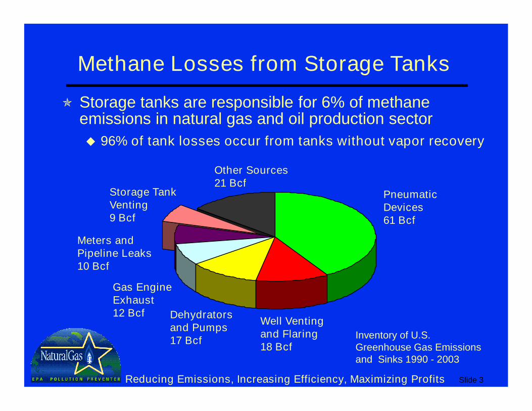
Methane Losses from Storage Tanks
Storage tanks are responsible for 6% of methane emissions in natural gas and oil production sector
96% of tank losses occur from tanks without vapor recovery
Inventory of U.S. Greenhouse Gas Emissions and Sinks 1990 - 2003
Pneumatic Devices61 Bcf
Meters andPipeline Leaks10 Bcf
Gas Engine Exhaust12 Bcf
Well Venting and Flaring18 Bcf
Storage Tank Venting9 Bcf
Other Sources 21 Bcf
Dehydrators and Pumps17 Bcf
Slide 4Reducing Emissions, Increasing Efficiency, Maximizing Profits
Sources of Methane Losses
9 Bcf methane lost from storage tanks each year from producers*
Flash losses - occur when crude is transferred from a gas-oil separator at higher pressure to an atmospheric pressure storage tank
Working losses - occur when crude levels change and when crude in tank is agitated
Standing losses - occur with daily and seasonal temperature and pressure changes
* Inventory of U.S. Greenhouse Gas Emissions and Sinks 1990 - 2003
Slide 5Reducing Emissions, Increasing Efficiency, Maximizing Profits
Methane Savings: Vapor Recovery Units
Capture up to 95% of hydrocarbon vapors vented from tanks
Recovered vapors have higher Btu content than pipeline quality natural gas
Recovered vapors are more valuable than natural gas and have multiple uses
Re-inject into sales pipeline
Use as on-site fuel
Send to processing plants for recovering NGLs
Slide 6Reducing Emissions, Increasing Efficiency, Maximizing Profits
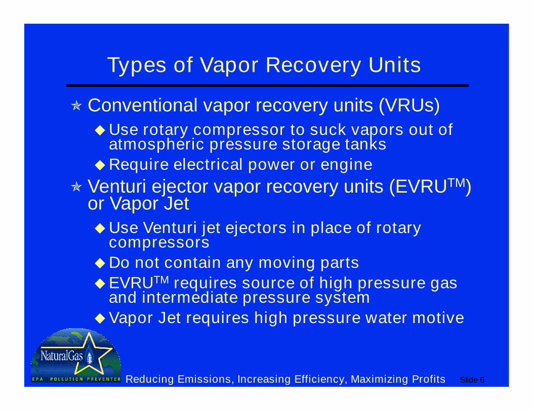
Types of Vapor Recovery Units
Conventional vapor recovery units (VRUs)Use rotary compressor to suck vapors out of
atmospheric pressure storage tanks
Require electrical power or engine
Venturi ejector vapor recovery units (EVRUTM) or Vapor JetUse Venturi jet ejectors in place of rotary
compressors
Do not contain any moving parts
EVRUTM requires source of high pressure gas and intermediate pressure system
Vapor Jet requires high pressure water motive
Slide 7Reducing Emissions, Increasing Efficiency, Maximizing Profits
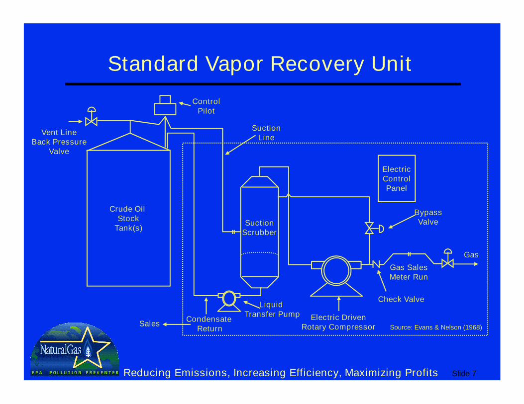
Standard Vapor Recovery Unit
Crude Oil Stock
Tank(s)
ControlPilot
Vent LineBack Pressure
Valve
SuctionScrubber
SuctionLine
Condensate Return
BypassValve
ElectricControlPanel
Electric DrivenRotary Compressor
Gas SalesMeter Run
Gas
Liquid Transfer Pump
Check Valve
Source: Evans & Nelson (1968)Sales
Slide 8Reducing Emissions, Increasing Efficiency, Maximizing Profits
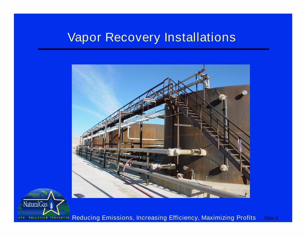
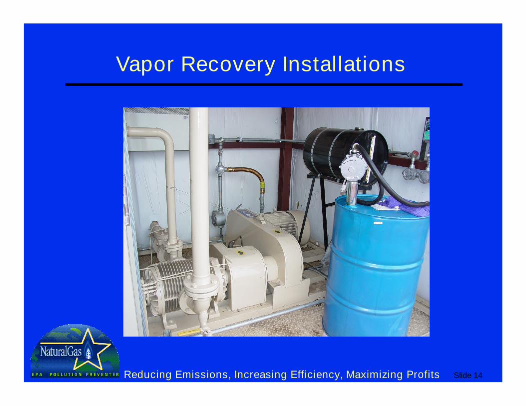
Vapor Recovery Installations
Slide 9Reducing Emissions, Increasing Efficiency, Maximizing Profits
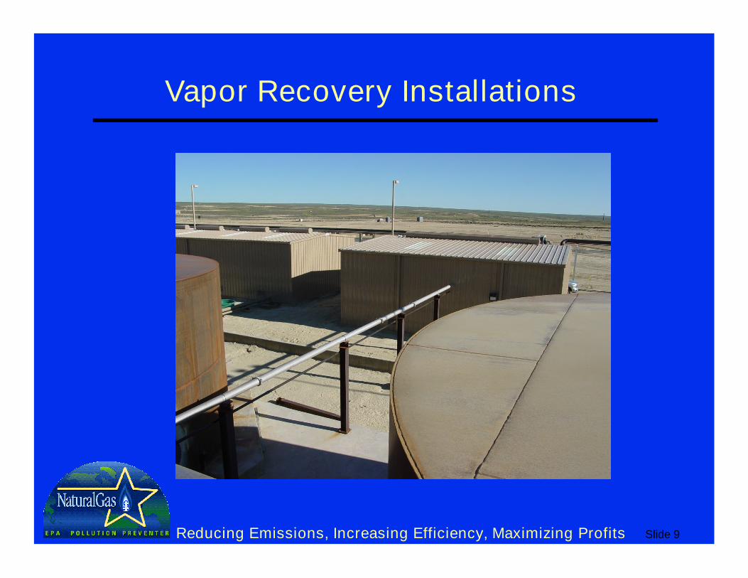
Vapor Recovery Installations
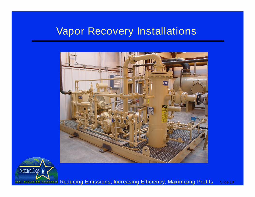
Slide 10Reducing Emissions, Increasing Efficiency, Maximizing Profits
Vapor Recovery Installations
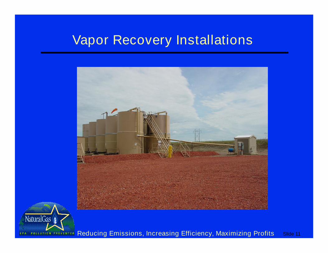
Slide 11Reducing Emissions, Increasing Efficiency, Maximizing Profits
Vapor Recovery Installations
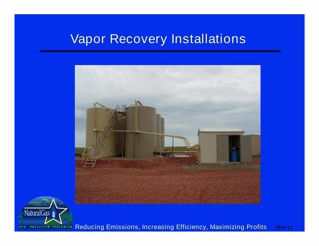
Slide 12Reducing Emissions, Increasing Efficiency, Maximizing Profits
Vapor Recovery Installations
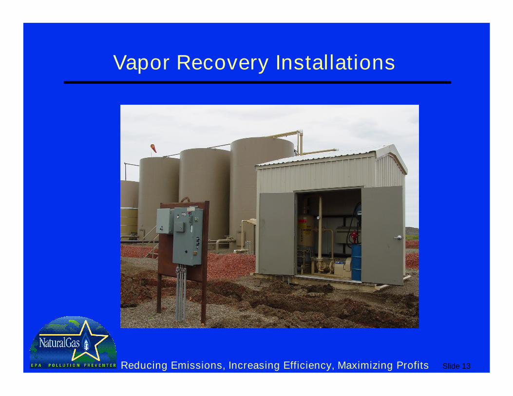
Slide 13Reducing Emissions, Increasing Efficiency, Maximizing Profits
Vapor Recovery Installations
Slide 14Reducing Emissions, Increasing Efficiency, Maximizing Profits
Vapor Recovery Installations
Slide 15Reducing Emissions, Increasing Efficiency, Maximizing Profits
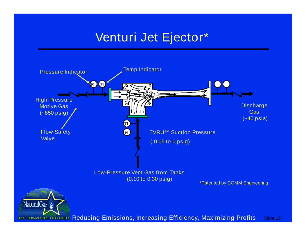
Venturi Jet Ejector*
High-PressureMotive Gas(~850 psig)
Flow Safety Valve
Pressure Indicator Temp Indicator
PI TI
TI
PI
(-0.05 to 0 psig)
Low-Pressure Vent Gas from Tanks(0.10 to 0.30 psig)
PI TI
Discharge Gas
(~40 psia)
EVRUTM Suction Pressure
*Patented by COMM Engineering
Slide 16Reducing Emissions, Increasing Efficiency, Maximizing Profits
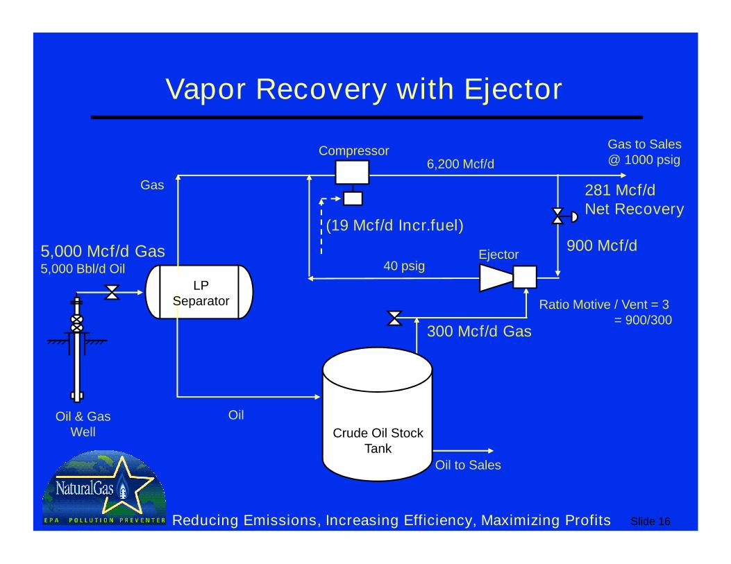
Vapor Recovery with Ejector
Oil to Sales
Gas to Sales@ 1000 psig
LP Separator
Oil
Gas
Compressor
Ejector
Oil & Gas Well
5,000 Mcf/d Gas5,000 Bbl/d Oil
900 Mcf/d
Ratio Motive / Vent = 3= 900/300
300 Mcf/d Gas
40 psig
6,200 Mcf/d
Crude Oil Stock Tank
(19 Mcf/d Incr.fuel)
281 Mcf/dNet Recovery
Slide 17Reducing Emissions, Increasing Efficiency, Maximizing Profits
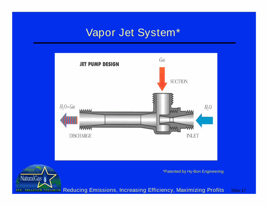
Vapor Jet System*
*Patented by Hy-Bon Engineering
Slide 18Reducing Emissions, Increasing Efficiency, Maximizing Profits
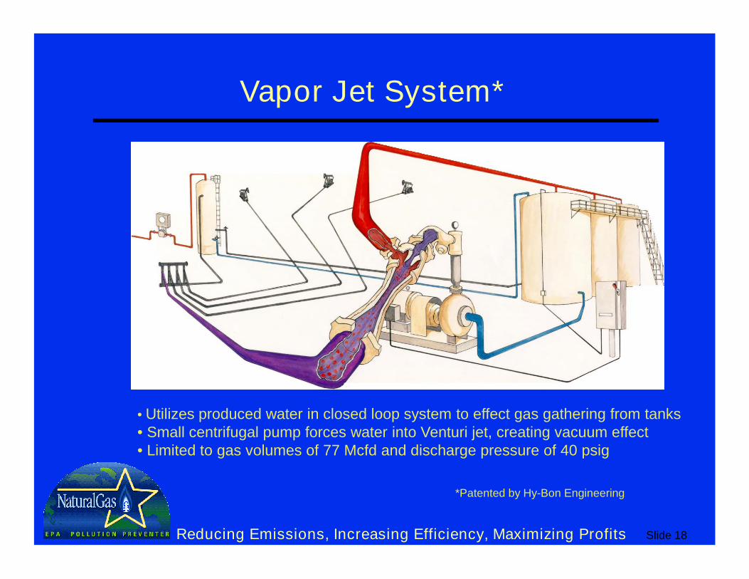
Vapor Jet System*
*Patented by Hy-Bon Engineering
• Utilizes produced water in closed loop system to effect gas gathering from tanks• Small centrifugal pump forces water into Venturi jet, creating vacuum effect • Limited to gas volumes of 77 Mcfd and discharge pressure of 40 psig
Slide 19Reducing Emissions, Increasing Efficiency, Maximizing Profits
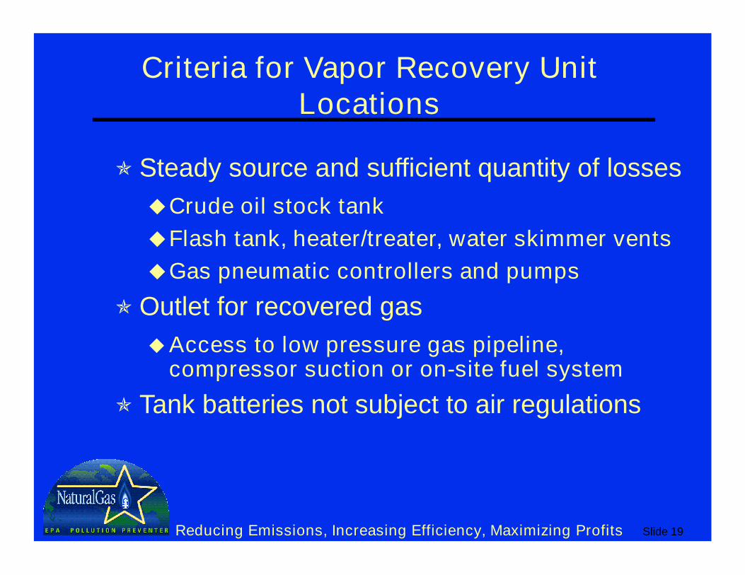
Criteria for Vapor Recovery Unit Locations
Steady source and sufficient quantity of losses
Crude oil stock tank
Flash tank, heater/treater, water skimmer vents
Gas pneumatic controllers and pumps
Outlet for recovered gas
Access to low pressure gas pipeline, compressor suction or on-site fuel system
Tank batteries not subject to air regulations
Slide 20Reducing Emissions, Increasing Efficiency, Maximizing Profits
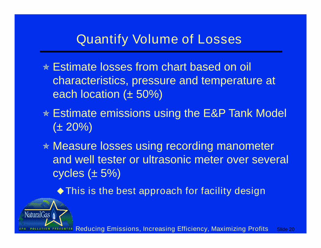
Quantify Volume of Losses
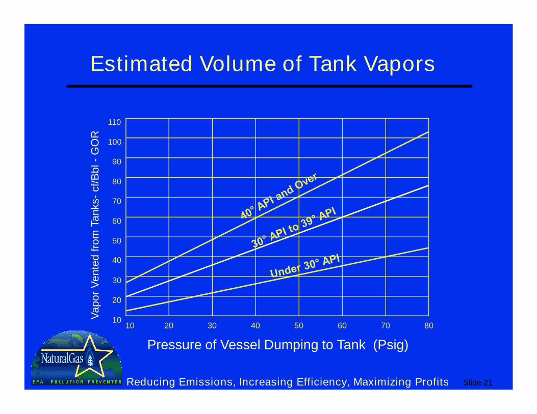
Estimate losses from chart based on oil characteristics, pressure and temperature at each location (± 50%)
Estimate emissions using the E&P Tank Model (± 20%)
Measure losses using recording manometer and well tester or ultrasonic meter over several cycles (± 5%)
This is the best approach for facility design
Slide 21Reducing Emissions, Increasing Efficiency, Maximizing Profits
Estimated Volume of Tank Vapors
Pressure of Vessel Dumping to Tank (Psig)
Vap
or
Ven
ted
fro
m T
an
ks-
cf/
Bb
l -G
OR
110
100
90
80
70
60
50
40
30
10
20
10 20 30 40 50 60 70 80
Slide 22Reducing Emissions, Increasing Efficiency, Maximizing Profits
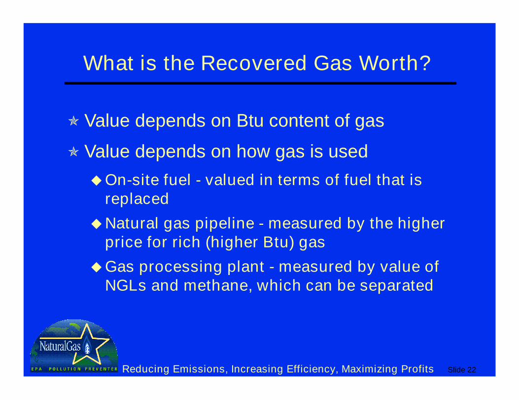
What is the Recovered Gas Worth?
Value depends on Btu content of gas
Value depends on how gas is used
On-site fuel - valued in terms of fuel that is replaced
Natural gas pipeline - measured by the higher price for rich (higher Btu) gas
Gas processing plant - measured by value of NGLs and methane, which can be separated
Slide 23Reducing Emissions, Increasing Efficiency, Maximizing Profits
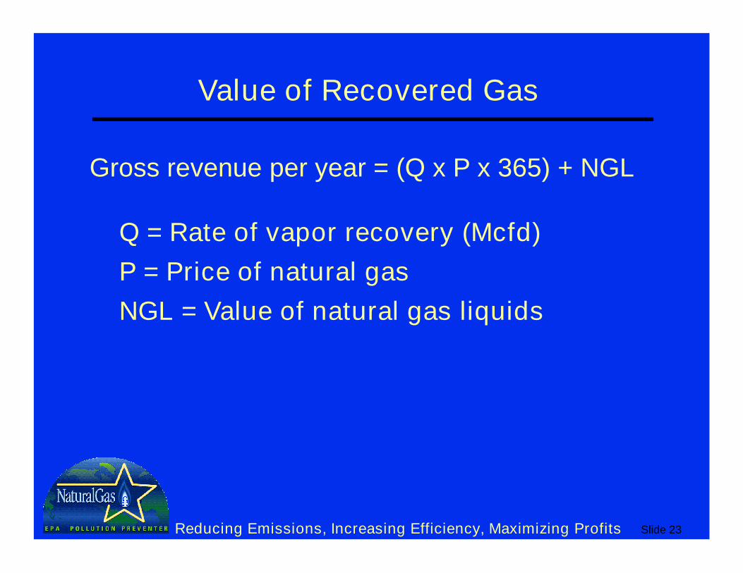
Value of Recovered Gas
Gross revenue per year = (Q x P x 365) + NGL
Q = Rate of vapor recovery (Mcfd)
P = Price of natural gas
NGL = Value of natural gas liquids
Slide 24Reducing Emissions, Increasing Efficiency, Maximizing Profits
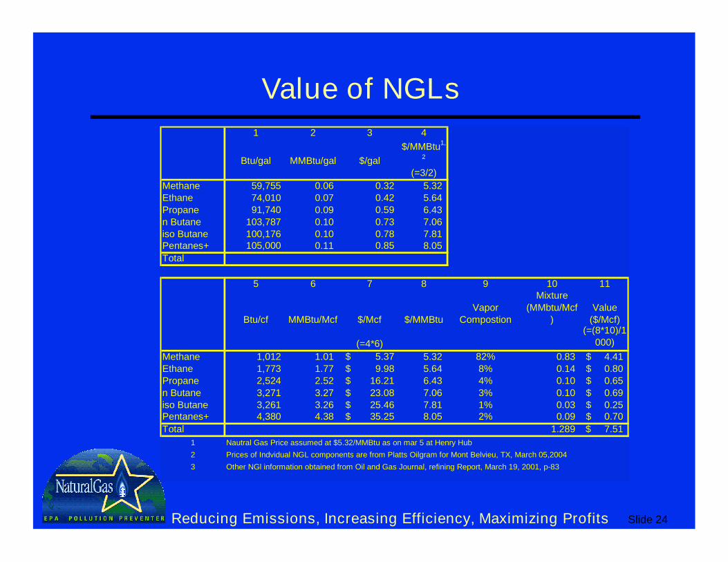
Value of NGLs
1 2 3 4
Btu/gal MMBtu/gal $/gal
$/MMBtu1,
2
(=3/2)
Methane 59,755 0.06 0.32 5.32Ethane 74,010 0.07 0.42 5.64Propane 91,740 0.09 0.59 6.43n Butane 103,787 0.10 0.73 7.06iso Butane 100,176 0.10 0.78 7.81Pentanes+ 105,000 0.11 0.85 8.05
Total
5 6 7 8 9 10 11
Btu/cf MMBtu/Mcf $/Mcf $/MMBtuVapor
Compostion
Mixture (MMbtu/Mcf
)Value
($/Mcf)
(=4*6)
(=(8*10)/1000)
Methane 1,012 1.01 5.37$ 5.32 82% 0.83 4.41$ Ethane 1,773 1.77 9.98$ 5.64 8% 0.14 0.80$ Propane 2,524 2.52 16.21$ 6.43 4% 0.10 0.65$ n Butane 3,271 3.27 23.08$ 7.06 3% 0.10 0.69$ iso Butane 3,261 3.26 25.46$ 7.81 1% 0.03 0.25$ Pentanes+ 4,380 4.38 35.25$ 8.05 2% 0.09 0.70$
Total 1.289 7.51$
1 Nautral Gas Price assumed at $5.32/MMBtu as on mar 5 at Henry Hub
2 Prices of Indvidual NGL components are from Platts Oilgram for Mont Belvieu, TX, March 05,2004
3 Other NGl information obtained from Oil and Gas Journal, refining Report, March 19, 2001, p-83
Slide 25Reducing Emissions, Increasing Efficiency, Maximizing Profits
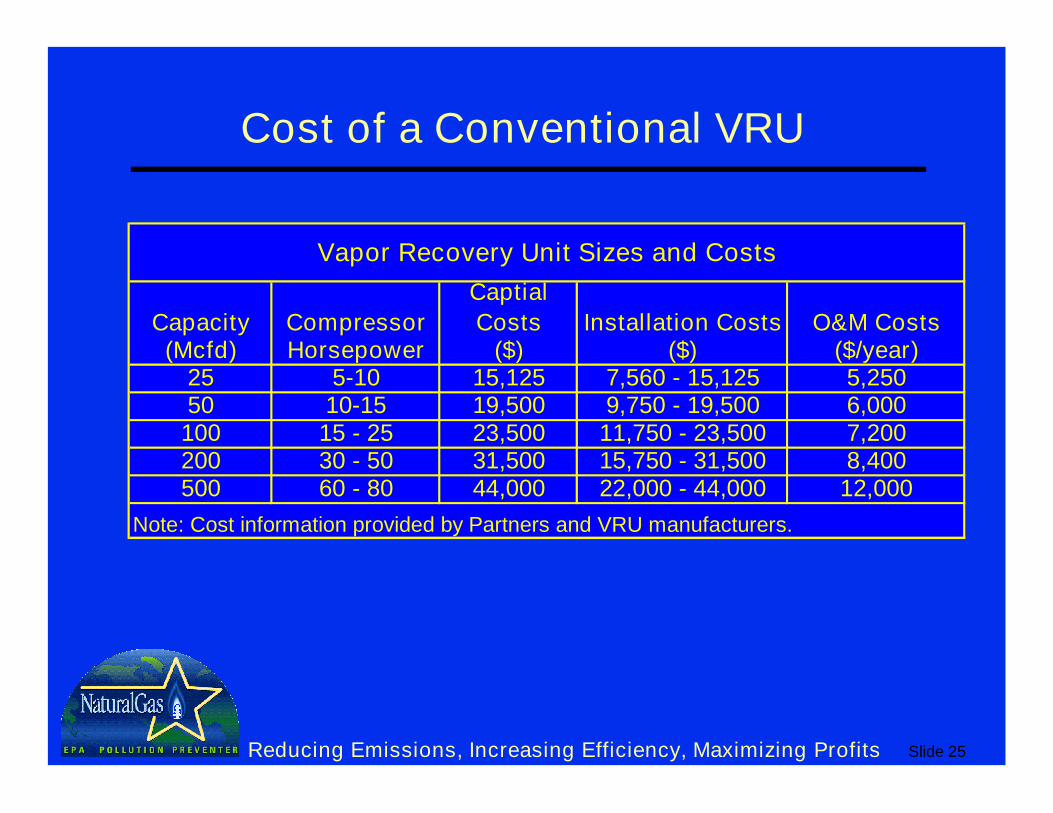
Cost of a Conventional VRU
Capacity Compressor
Captial
Costs Installation Costs O&M Costs(Mcfd) Horsepower ($) ($) ($/year)
25 5-10 15,125 7,560 - 15,125 5,25050 10-15 19,500 9,750 - 19,500 6,000100 15 - 25 23,500 11,750 - 23,500 7,200200 30 - 50 31,500 15,750 - 31,500 8,400500 60 - 80 44,000 22,000 - 44,000 12,000
Vapor Recovery Unit Sizes and Costs
Note: Cost information provided by Partners and VRU manufacturers.
Slide 26Reducing Emissions, Increasing Efficiency, Maximizing Profits
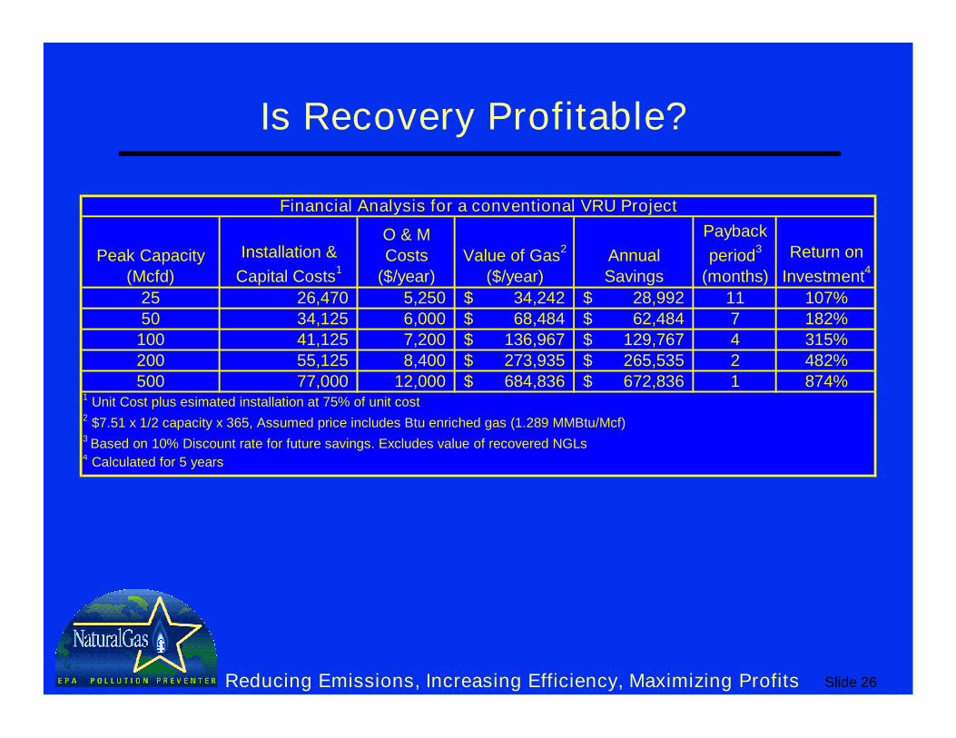
Is Recovery Profitable?
Peak Capacity (Mcfd)
Installation &
Capital Costs1
O & M Costs
($/year)Value of Gas
2
($/year)Annual Savings
Payback
period3
(months)
Return on
Investment4
25 26,470 5,250 34,242$ 28,992$ 11 107%50 34,125 6,000 68,484$ 62,484$ 7 182%100 41,125 7,200 136,967$ 129,767$ 4 315%200 55,125 8,400 273,935$ 265,535$ 2 482%500 77,000 12,000 684,836$ 672,836$ 1 874%
1 Unit Cost plus esimated installation at 75% of unit cost2 $7.51 x 1/2 capacity x 365, Assumed price includes Btu enriched gas (1.289 MMBtu/Mcf)3 Based on 10% Discount rate for future savings. Excludes value of recovered NGLs4 Calculated for 5 years
Financial Analysis for a conventional VRU Project
Slide 27Reducing Emissions, Increasing Efficiency, Maximizing Profits
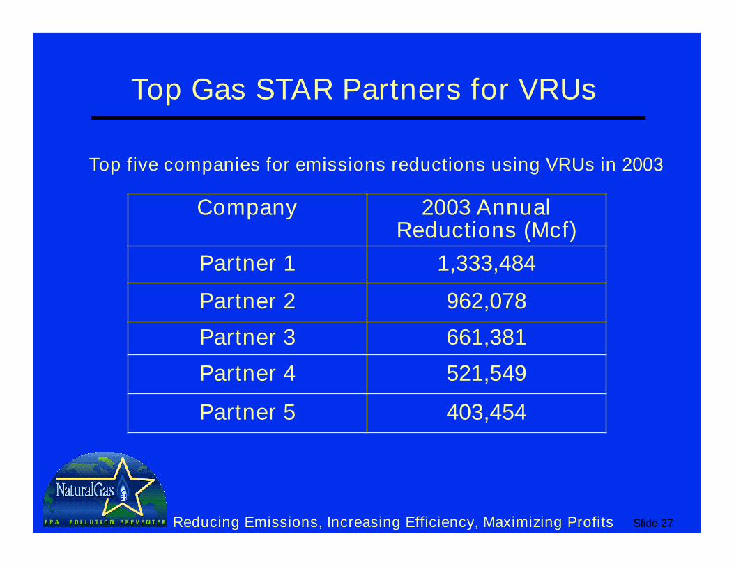
Top Gas STAR Partners for VRUs
Top five companies for emissions reductions using VRUs in 2003
Company 2003 Annual Reductions (Mcf)
Partner 1 1,333,484
Partner 2 962,078
Partner 3 661,381
Partner 4 521,549
Partner 5 403,454
Slide 28Reducing Emissions, Increasing Efficiency, Maximizing Profits
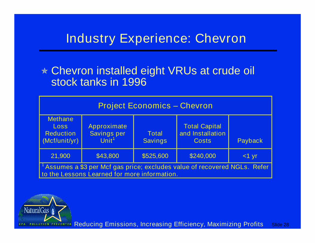
Industry Experience: Chevron
Chevron installed eight VRUs at crude oil stock tanks in 1996
Project Economics – Chevron
Methane Loss
Reduction (Mcf/unit/yr)
Approximate Savings per
Unit1Total
Savings
Total Capital and Installation
Costs Payback
21,900 $43,800 $525,600 $240,000 <1 yr
1 Assumes a $3 per Mcf gas price; excludes value of recovered NGLs. Refer to the Lessons Learned for more information.
Slide 29Reducing Emissions, Increasing Efficiency, Maximizing Profits
Industry Experience: Devon Energy
For 5 years Devon employed the Vapor Jet system and recovered more than 55 MMcf of gas from crude oil stock tanks
Prior to installing the system, tank vapor emissions were ~ 20 Mcfd
Installed a system with maximum capacity of 77 Mcfd anticipating production increases
Revenue was about $91,000 with capital cost of $25,000 and operating expenses less than $0.40/Mcf of gas recoveredThis paid back investment in under 2 years
Slide 30Reducing Emissions, Increasing Efficiency, Maximizing Profits
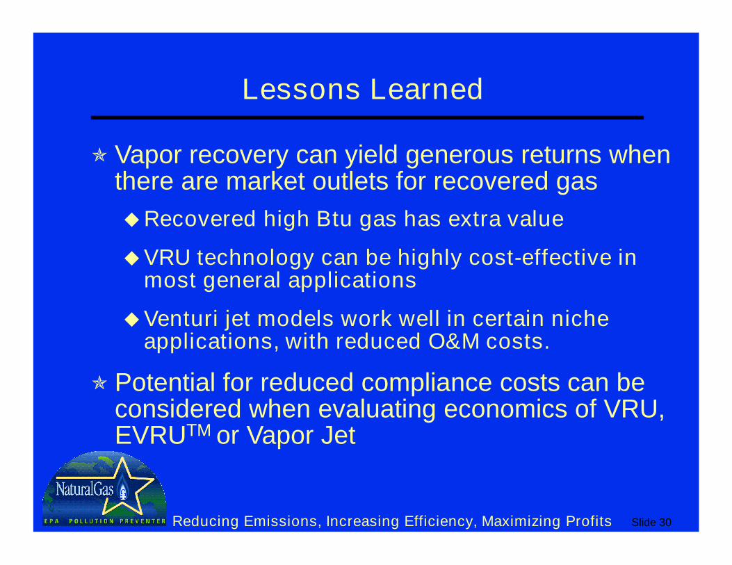
Lessons Learned
Vapor recovery can yield generous returns when there are market outlets for recovered gas
Recovered high Btu gas has extra value
VRU technology can be highly cost-effective in most general applications
Venturi jet models work well in certain niche applications, with reduced O&M costs.
Potential for reduced compliance costs can be considered when evaluating economics of VRU, EVRUTM or Vapor Jet
Slide 31Reducing Emissions, Increasing Efficiency, Maximizing Profits
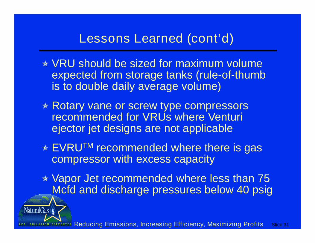
Lessons Learned (cont’d)
VRU should be sized for maximum volume expected from storage tanks (rule-of-thumb is to double daily average volume)
Rotary vane or screw type compressors recommended for VRUs where Venturi ejector jet designs are not applicable
EVRUTM recommended where there is gas compressor with excess capacity
Vapor Jet recommended where less than 75 Mcfd and discharge pressures below 40 psig
Slide 32Reducing Emissions, Increasing Efficiency, Maximizing Profits
Discussion Questions
To what extent are you implementing this BMP?
How can this BMP be improved upon or altered for use in your operation(s)?
What is stopping you from implementing this technology (technological, economic, lack of information, focus, manpower, etc.)?