Embed Size (px)
Citation preview
WS001966A
2. Remove the impeller screw.
If applicable, use the rod.
WS001988A
Figure 15: C-impeller
WS001982A
Figure 16: D-impeller
3. Remove the washer.
4. Remove the impeller.
Use the impeller puller or the crowbars.
WS001978A
Figure 17: D-impeller
6.4.1.2 Install the impeller: C, D1. Prepare the shaft:
a) Make sure that the end of the shaft is clean and free from burrs.
6 Maintenance
48 Flygt 3127 Installation, Operation, and Maintenance Manual
Polish off any flaws with a fine emery cloth.b) Fit the spacer ring to the shaft (applicable for seal type O).c) Make sure that the parallel key is seated in the keyway on the shaft.d) Lubricate the end of the shaft.
2. Mount the impeller:
a) Lubricate the impeller screw threads and contact surface.
Ensure that all parts are clean.b) Fit the washer on the lubricated impeller screw.c) Press the impeller onto the shaft with the impeller screw.
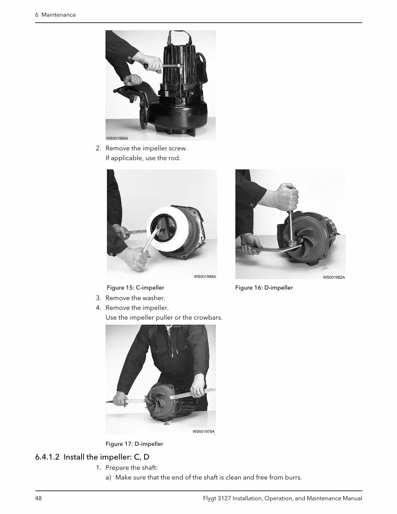
3. Tighten the impeller screw.
If applicable, use the rod.
Tightening torque: 80 Nm (59 ft-lbs)
WS001941A
Check that the impeller can rotate freely.
4. Mount the suction cover (if applicable):
a) Fit a new lubricated O-ring to the suction cover.
WS002015A
b) Fit the suction cover.c) Fit and tighten the lubricated screws.
Tightening torque: 57 Nm (42 ft-lb).
5. Mount the pump housing:
a) D-impeller: Fit a new lubricated O-ring to the pump housing.b) Fit the pump housing.c) Fit and tighten the lubricated screws.
Tightening torque: 57 Nm (42 ft-lb).
6 Maintenance
Flygt 3127 Installation, Operation, and Maintenance Manual 49
WS002018A
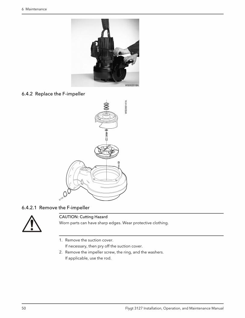
6.4.2 Replace the F-impeller
WS0
0614
1A
6.4.2.1 Remove the F-impeller
CAUTION: Cutting Hazard
Worn parts can have sharp edges. Wear protective clothing.
1. Remove the suction cover.
If necessary, then pry off the suction cover.
2. Remove the impeller screw, the ring, and the washers.
If applicable, use the rod.
6 Maintenance
50 Flygt 3127 Installation, Operation, and Maintenance Manual
WS001976A
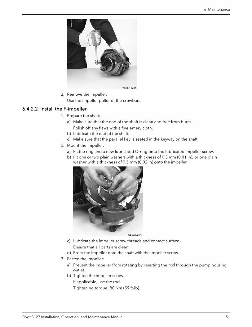
3. Remove the impeller.
Use the impeller puller or the crowbars.
6.4.2.2 Install the F-impeller1. Prepare the shaft:
a) Make sure that the end of the shaft is clean and free from burrs.
Polish off any flaws with a fine emery cloth.b) Lubricate the end of the shaft.c) Make sure that the parallel key is seated in the keyway on the shaft.
2. Mount the impeller:
a) Fit the ring and a new lubricated O-ring onto the lubricated impeller screw.b) Fit one or two plain washers with a thickness of 0.3 mm (0.01 in), or one plain
washer with a thickness of 0.5 mm (0.02 in) onto the impeller.
WS002021A
c) Lubricate the impeller screw threads and contact surface.
Ensure that all parts are clean.d) Press the impeller onto the shaft with the impeller screw.
3. Fasten the impeller:
a) Prevent the impeller from rotating by inserting the rod through the pump housingoutlet.
b) Tighten the impeller screw.
If applicable, use the rod.
Tightening torque: 80 Nm (59 ft-lb).
6 Maintenance
Flygt 3127 Installation, Operation, and Maintenance Manual 51
WS001940A
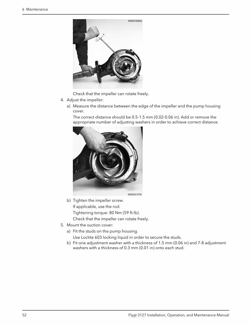
Check that the impeller can rotate freely.
4. Adjust the impeller:
a) Measure the distance between the edge of the impeller and the pump housingcover.
The correct distance should be 0.5-1.5 mm (0.02-0.06 in). Add or remove theappropriate number of adjusting washers in order to achieve correct distance.
WS002107A
b) Tighten the impeller screw.
If applicable, use the rod.
Tightening torque: 80 Nm (59 ft-lb).
Check that the impeller can rotate freely.
5. Mount the suction cover:
a) Fit the studs on the pump housing.
Use Loctite 603 locking liquid in order to secure the studs.b) Fit one adjustment washer with a thickness of 1.5 mm (0.06 in) and 7-8 adjustment
washers with a thickness of 0.3 mm (0.01 in) onto each stud.
6 Maintenance
52 Flygt 3127 Installation, Operation, and Maintenance Manual
WS002014A
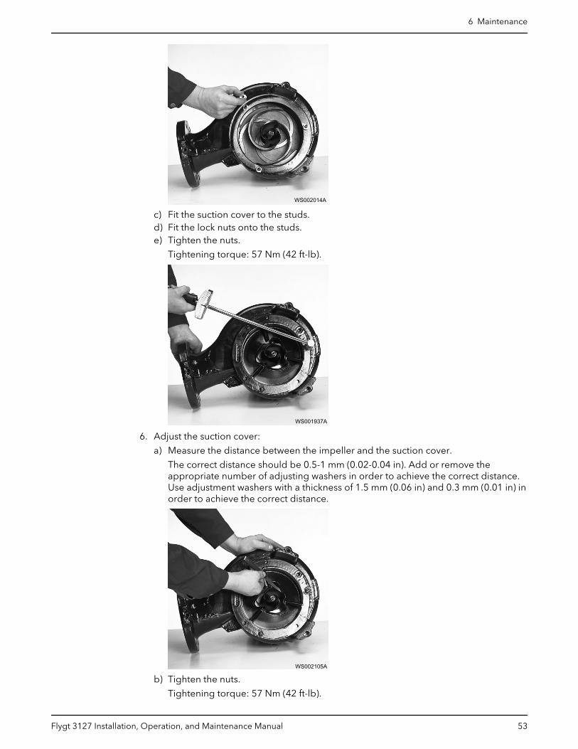
c) Fit the suction cover to the studs.d) Fit the lock nuts onto the studs.e) Tighten the nuts.
Tightening torque: 57 Nm (42 ft-lb).
WS001937A
6. Adjust the suction cover:
a) Measure the distance between the impeller and the suction cover.
The correct distance should be 0.5-1 mm (0.02-0.04 in). Add or remove theappropriate number of adjusting washers in order to achieve the correct distance.Use adjustment washers with a thickness of 1.5 mm (0.06 in) and 0.3 mm (0.01 in) inorder to achieve the correct distance.
WS002105A
b) Tighten the nuts.
Tightening torque: 57 Nm (42 ft-lb).
6 Maintenance
Flygt 3127 Installation, Operation, and Maintenance Manual 53

WS001937A
7. Raise the pump to a vertical position.
Check that the impeller can rotate freely.
6.4.3 Replace the H-impellerW
S006
142A
6.4.3.1 Remove the H-impeller
CAUTION: Cutting Hazard
Worn parts can have sharp edges. Wear protective clothing.
1. Remove the suction cover.
If necessary, then pry off the suction cover.
2. Remove the impeller screw and washer.
If applicable, use the rod.
3. Remove the impeller from the shaft:
a) Insert a M16 screw into the square nut.b) Turn the screw to push off the impeller.
4. Remove the screw and the square nut.
6 Maintenance
54 Flygt 3127 Installation, Operation, and Maintenance Manual
6.4.3.2 Install the H-impeller1. Prepare the shaft:
a) Make sure that the end of the shaft is clean and free from burrs.
Polish off any flaws with a fine emery cloth.b) Make sure that the parallel key is seated in the keyway on the shaft.
2. Mount the impeller:
a) Fit the washer and square nut to the lubricated impeller screw.b) Press the impeller onto the shaft with the impeller screw.
3. Tighten the impeller screw.
Tightening torque: 80 Nm (59 ft-lbs)
If applicable, use the rod.
Check that the impeller can rotate freely.
4. Mount the suction cover:
a) Fit the studs on the pump housing.b) Fit the first hexagon nut onto the studs.c) Fit the suction cover to the studs.
Make sure that the impeller rotates freely from the suction cover before tighteningthe hexagon nuts. The clearance between the impeller and the suction covershould be as small as possible.
d) Fit the second hexagon nuts onto the studs.e) Tighten the nuts.
Tightening torque: 57 Nm (42 ft-lb).
5. Raise the pump to a vertical position.
Check that the impeller can rotate freely.
6.4.4 Replace the M-impeller
WS0
0614
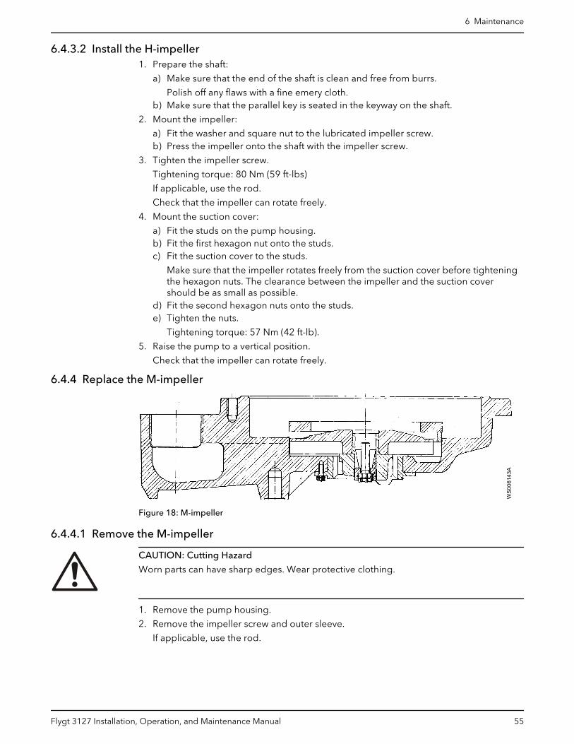
3AFigure 18: M-impeller
6.4.4.1 Remove the M-impeller
CAUTION: Cutting Hazard
Worn parts can have sharp edges. Wear protective clothing.
1. Remove the pump housing.
2. Remove the impeller screw and outer sleeve.
If applicable, use the rod.
6 Maintenance
Flygt 3127 Installation, Operation, and Maintenance Manual 55
WS001977A
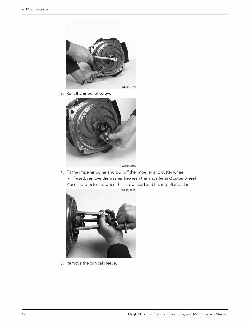
3. Refit the impeller screw.
WS001993A
4. Fit the impeller puller and pull off the impeller and cutter wheel.
– If used, remove the washer between the impeller and cutter wheel.
Place a protector between the screw head and the impeller puller.WS002006A
5. Remove the conical sleeve.
6 Maintenance
56 Flygt 3127 Installation, Operation, and Maintenance Manual

WS001987A
6.4.4.2 Install the M-impeller1. Prepare the shaft:
a) Polish off any flaws with a fine emery cloth.
The end of the shaft must be clean and free from burrs.b) Coat the inner conic, the outer cylindrical surfaces, and the thread of the conical
sleeve with a thin layer of grease.
The proper lubrication is grease for bearings, for example Exxon Mobil Unirex N3,Mobil Mobilith SHC 220 or equivalent.
NOTICE:
Surplus grease can cause the impeller to become loose. Remove surplus greasefrom conical and/or cylindrical surfaces of shafts and/or sleeves.
WS0
0689
5A
2. Mount the impeller:
a) Fit the conical sleeve onto the shaft.
6 Maintenance
Flygt 3127 Installation, Operation, and Maintenance Manual 57
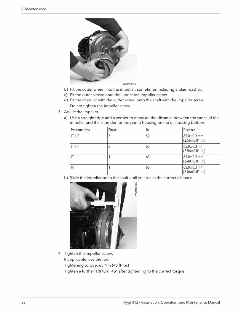
WS002081A
b) Fit the cutter wheel into the impeller, sometimes including a plain washer.c) Fit the outer sleeve onto the lubricated impeller screw.d) Fit the impeller with the cutter wheel onto the shaft with the impeller screw.
Do not tighten the impeller screw.
3. Adjust the impeller:
a) Use a straightedge and a vernier to measure the distance between the vanes of theimpeller and the shoulder for the pump housing on the oil housing bottom.
Pressure class Phase Hz Distance
LT, HT 3 50 65.0±0.3 mm(2.56±0.01 in.)
LT, HT 3 60 65.0±0.3 mm(2.56±0.01 in.)
LT 1 60 63.0±0.3 mm(2.48±0.01 in.)
HT 1 60 65.0±0.3 mm(2.56±0.01 in.)
b) Slide the impeller on to the shaft until you reach the correct distance.
WS0
0194
3A
4. Tighten the impeller screw.
If applicable, use the rod.
Tightening torque: 65 Nm (48 ft-lbs)
Tighten a further 1/8 turn, 45° after tightening to the correct torque.
6 Maintenance
58 Flygt 3127 Installation, Operation, and Maintenance Manual
WS001939A
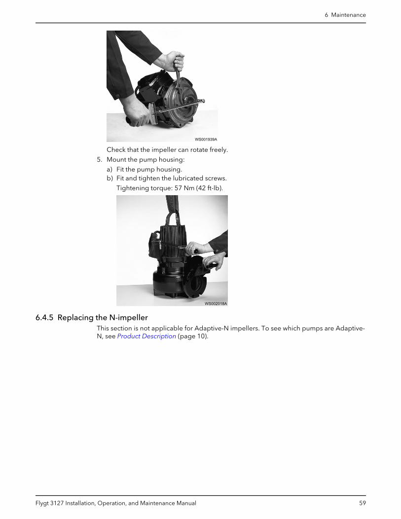
Check that the impeller can rotate freely.
5. Mount the pump housing:
a) Fit the pump housing.b) Fit and tighten the lubricated screws.
Tightening torque: 57 Nm (42 ft-lb).
WS002018A
6.4.5 Replacing the N-impellerThis section is not applicable for Adaptive-N impellers. To see which pumps are Adaptive-N, see Product Description (page 10).
6 Maintenance
Flygt 3127 Installation, Operation, and Maintenance Manual 59
1
2
3
4
5
6
7
WS008331B
8
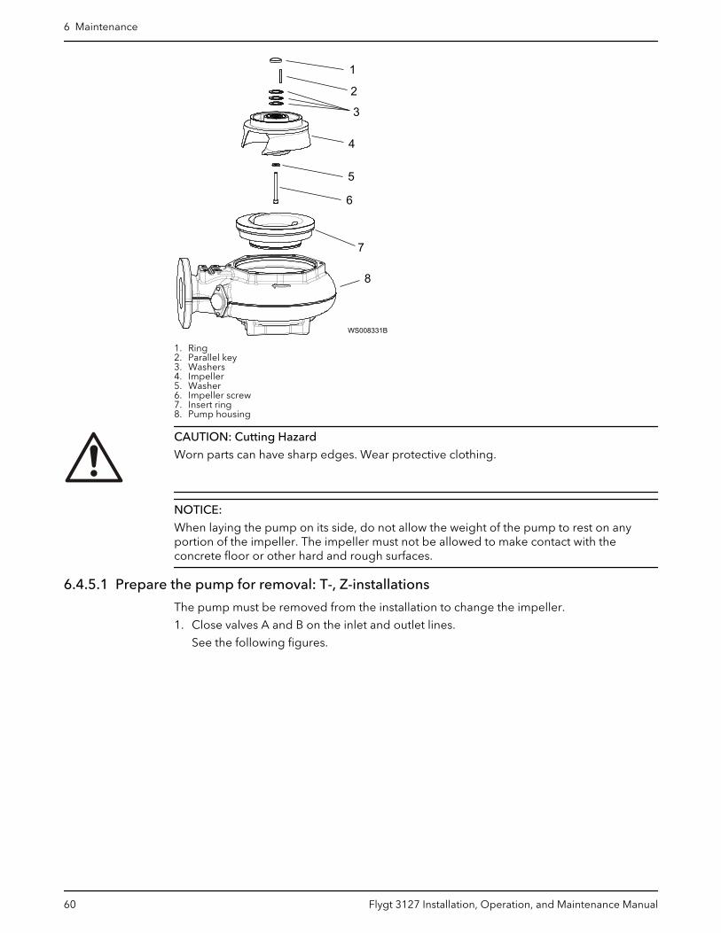
1. Ring2. Parallel key3. Washers4. Impeller5. Washer6. Impeller screw7. Insert ring8. Pump housing
CAUTION: Cutting Hazard
Worn parts can have sharp edges. Wear protective clothing.
NOTICE:
When laying the pump on its side, do not allow the weight of the pump to rest on anyportion of the impeller. The impeller must not be allowed to make contact with theconcrete floor or other hard and rough surfaces.
6.4.5.1 Prepare the pump for removal: T-, Z-installations
The pump must be removed from the installation to change the impeller.
1. Close valves A and B on the inlet and outlet lines.
See the following figures.
6 Maintenance
60 Flygt 3127 Installation, Operation, and Maintenance Manual

WS0
0839
1B
A
C
B1
2
3
D
4
1. Outlet line2. Inlet line3. Line to drain4. Air vent
Figure 19: Valves A-D for T-installation (generic pump shown)
B1
WS0
0839
2B
A
2
C
31. Outlet line2. Inlet line3. Line to drain
Figure 20: Valves A-C for Z-installation (generic pump shown)
2. Drain the pump by opening valve C on the drain line.
3. Remove the pump from the installation.
6.4.5.2 Remove the N-impeller: P, S, T, Z installations
This section is not applicable for Adaptive-N impellers. To see which pumps are Adaptive-N, see Product Description (page 10).
1. Remove the pump housing.
2. Remove the plug.
3. Remove the impeller screw.
4. Remove the impeller.
Use the impeller puller or the crowbars.
5. Remove the plain washers and the adjustment washers.
6 Maintenance
Flygt 3127 Installation, Operation, and Maintenance Manual 61

6.4.5.3 Install the N-impeller: P, S, T, Z installations
This section is not applicable for Adaptive-N impellers. To see which pumps are Adaptive-N, see Product Description (page 10).
WARNING: Crush Hazard
Beware of the pinch point hazard between the rotating impeller and the guide pin.
12
3
4
56
WS0
0839
3B
1. Ring2. Parallel key3. Washers4. Impeller5. Washer6. Impeller screw
1. Prepare the shaft:
a) Make sure that the end of the shaft is clean and free from burrs.
Polish off any flaws with a fine emery cloth.b) Make sure that the ring under the seal is mounted. See the following figure.
12
3
WS0
0840
2A
1. Ring2. Parallel key3. Washers
c) Make sure that the parallel key is seated in the keyway on the shaft.d) Grease the shaft end.e) Fit the adjustment washers.
6 Maintenance
62 Flygt 3127 Installation, Operation, and Maintenance Manual

There are three thicknesses for adjustment washers: 0.3, 0.5 and 1.5 mm (0.012,0.02 and 0.06 in).
The adjustment washers are used to trim the impeller. The exact number ofadjustment washers is not known at this point. Start by inserting one shim of eachthickness (1×0.3mm + 1×0.5mm + 1×1.5mm = 2.3 mm). This will create a distancebetween the impeller and the insert ring that can be measured and adjusted inlater steps.
2. Mount the impeller:
a) Fit the impeller to the shaft.b) Fit the washer on the lubricated impeller screw.c) Tighten the impeller screw to compress the adjustment washers.
3. Mount the pump housing:
a) Fit the new O-ring to the pump housing.b) Fit and tighten the lubricated screws.
4. Trim the impeller clearance:
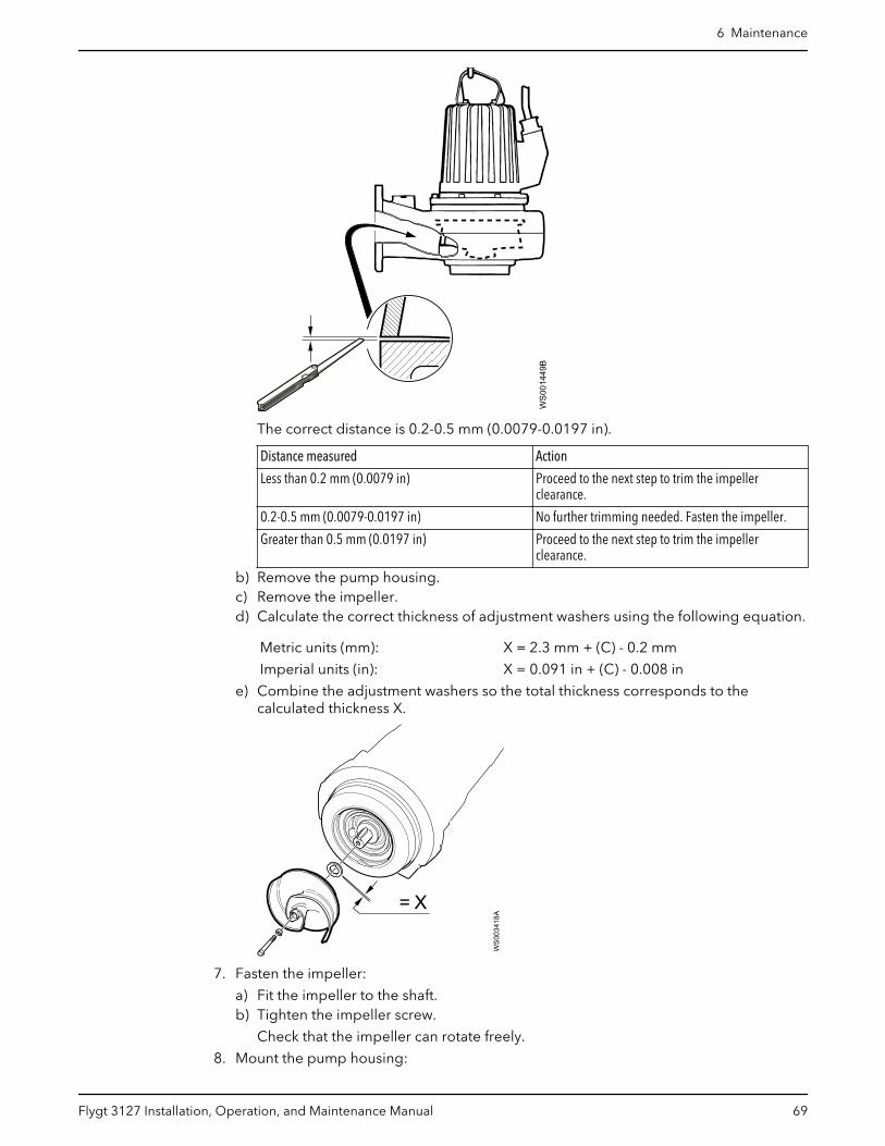
a) Measure the distance (C) with an extended feeler gauge.
WS0
0144
9B
The correct distance is 0.2-0.5 mm (0.0079-0.0197 in).
Distance measured Action
Less than 0.2 mm (0.0079 in) Proceed to the next step to trim the impellerclearance.
0.2-0.5 mm (0.0079-0.0197 in) No further trimming needed. Fasten the impeller.
Greater than 0.5 mm (0.0197 in) Proceed to the next step to trim the impellerclearance.
b) Remove the pump housing.c) Remove the impeller.d) Calculate the correct thickness of adjustment washers using the following equation.
Metric units (mm): X = 2.3 mm + (C) - 0.2 mm
Imperial units (in): X = 0.091 in + (C) - 0.008 in
e) Combine the adjustment washers so the total thickness corresponds to thecalculated thickness X.
6 Maintenance
Flygt 3127 Installation, Operation, and Maintenance Manual 63
= X
WS
0034
18A
5. Fasten the impeller:
a) Fit the impeller to the shaft.b) Tighten the impeller screw.c) Fit the pump housing.d) Fit and tighten the lubricated screws for the pump housing.
Tightening torque: 57 Nm (42 ft-lb).e) Tighten the impeller screw.
Tightening torque: 80 Nm (59 ft-lb).f) Check that the impeller can rotate freely.g) Check with a feeler gauge that the gap is 0.2–0.5 mm.
6. Re-install the pump.
T-installations: See the instructions in T-installation: Bleed air before starting pump(page 37).
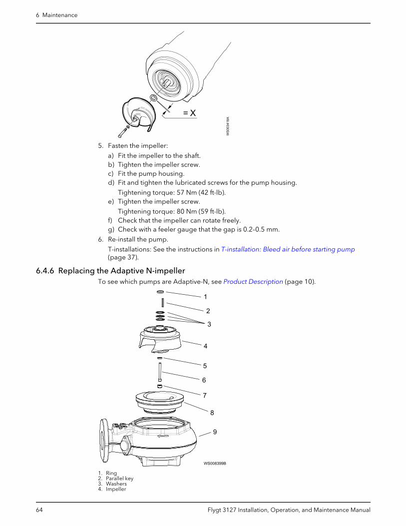
6.4.6 Replacing the Adaptive N-impellerTo see which pumps are Adaptive-N, see Product Description (page 10).
1
2
3
4
5
6
7
8
WS008399B
9
1. Ring2. Parallel key3. Washers4. Impeller
6 Maintenance
64 Flygt 3127 Installation, Operation, and Maintenance Manual

5. Washer6. Impeller screw7. Plug8. Insert ring9. Pump housing
CAUTION: Cutting Hazard
Worn parts can have sharp edges. Wear protective clothing.
NOTICE:
When laying the pump on its side, do not allow the weight of the pump to rest on anyportion of the impeller. The impeller must not be allowed to make contact with theconcrete floor or other hard and rough surfaces.
6.4.6.1 Prepare the pump for removal: T-, Z-installations
The pump must be removed from the installation to change the impeller.
1. Close valves A and B on the inlet and outlet lines.
See the following figures.
WS0
0839
1B
A
C
B1
2
3
D
4
1. Outlet line2. Inlet line3. Line to drain4. Air vent
Figure 21: Valves A-D for T-installation (generic pump shown)
6 Maintenance
Flygt 3127 Installation, Operation, and Maintenance Manual 65

B1
WS0
0839
2B
A
2
C
31. Outlet line2. Inlet line3. Line to drain
Figure 22: Valves A-C for Z-installation (generic pump shown)
2. Drain the pump by opening valve C on the drain line.
3. Remove the pump from the installation.
6.4.6.2 Remove the Adaptive-N impeller: P, S, T, Z installations
To see which pumps are Adaptive-N, see Product Description (page 10).
1. Remove the pump housing.
2. Remove the plug.
See the figure in Replacing the Adaptive N-impeller (page 64).
3. Remove the impeller screw.
4. Remove the impeller.
Use the impeller puller or the crowbars.
5. Remove the plain washers and the adjustment washers.
6.4.6.3 Install the Adaptive-N impeller: P, S, T, Z installations
To see which pumps are Adaptive-N, see Product Description (page 10).
6 Maintenance
66 Flygt 3127 Installation, Operation, and Maintenance Manual
12
3
4
567W
S008
394B
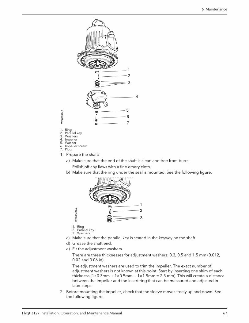
1. Ring2. Parallel key3. Washers4. Impeller5. Washer6. Impeller screw7. Plug
1. Prepare the shaft:
a) Make sure that the end of the shaft is clean and free from burrs.
Polish off any flaws with a fine emery cloth.b) Make sure that the ring under the seal is mounted. See the following figure.
12
3
WS0
0840
2A
1. Ring2. Parallel key3. Washers
c) Make sure that the parallel key is seated in the keyway on the shaft.d) Grease the shaft end.e) Fit the adjustment washers.
There are three thicknesses for adjustment washers: 0.3, 0.5 and 1.5 mm (0.012,0.02 and 0.06 in).
The adjustment washers are used to trim the impeller. The exact number ofadjustment washers is not known at this point. Start by inserting one shim of eachthickness (1×0.3mm + 1×0.5mm + 1×1.5mm = 2.3 mm). This will create a distancebetween the impeller and the insert ring that can be measured and adjusted inlater steps.
2. Before mounting the impeller, check that the sleeve moves freely up and down. Seethe following figure.
6 Maintenance
Flygt 3127 Installation, Operation, and Maintenance Manual 67
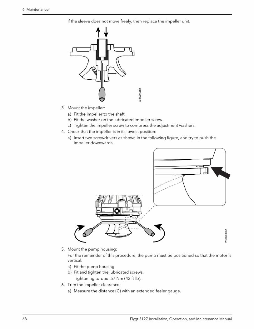
If the sleeve does not move freely, then replace the impeller unit.
WS0
0839
7B
3. Mount the impeller:
a) Fit the impeller to the shaft.b) Fit the washer on the lubricated impeller screw.c) Tighten the impeller screw to compress the adjustment washers.
4. Check that the impeller is in its lowest position:
a) Insert two screwdrivers as shown in the following figure, and try to push theimpeller downwards.
WS0
0838
6A
5. Mount the pump housing:
For the remainder of this procedure, the pump must be positioned so that the motor isvertical.
a) Fit the pump housing.b) Fit and tighten the lubricated screws.
Tightening torque: 57 Nm (42 ft-lb).
6. Trim the impeller clearance:
a) Measure the distance (C) with an extended feeler gauge.
6 Maintenance
68 Flygt 3127 Installation, Operation, and Maintenance Manual
WS0
0144
9B
The correct distance is 0.2-0.5 mm (0.0079-0.0197 in).
Distance measured Action
Less than 0.2 mm (0.0079 in) Proceed to the next step to trim the impellerclearance.
0.2-0.5 mm (0.0079-0.0197 in) No further trimming needed. Fasten the impeller.
Greater than 0.5 mm (0.0197 in) Proceed to the next step to trim the impellerclearance.
b) Remove the pump housing.c) Remove the impeller.d) Calculate the correct thickness of adjustment washers using the following equation.
Metric units (mm): X = 2.3 mm + (C) - 0.2 mm
Imperial units (in): X = 0.091 in + (C) - 0.008 in
e) Combine the adjustment washers so the total thickness corresponds to thecalculated thickness X.
= X
WS
0034
18A
7. Fasten the impeller:
a) Fit the impeller to the shaft.b) Tighten the impeller screw.
Check that the impeller can rotate freely.
8. Mount the pump housing:
6 Maintenance
Flygt 3127 Installation, Operation, and Maintenance Manual 69

a) Fit the pump housing.b) Fit and tighten the lubricated screws.
Tightening torque: 57 Nm (42 ft-lb).
9. Tighten the impeller screw.
Tightening torque: 80 Nm (59 ft-lb).
10.Check that the impeller can rotate freely.
11.Check with a feeler gauge that the clearance is 0.2–0.5 mm.
12.Fit the lubricated plug and tighten it.
Tightening torque: 20-40 Nm (15-30 ft-lb).
13.Re-install the pump.
T-installations: See the instructions in T-installation: Bleed air before starting pump(page 37).
6.5 Replace the propeller
WS0
0614
5A
Figure 23: Propeller
Required tools:
• 10 mm hexagon bit adapter with an extension of at least 125 mm (4.92 in.)• Rod (wooden or copper) for locking the propeller in place, if applicable• Propeller puller
If applicable, contact your local sales and service representative for correct type andsize.
• Two crowbars, if applicable
CAUTION: Cutting Hazard
Worn parts can have sharp edges. Wear protective clothing.
6 Maintenance
70 Flygt 3127 Installation, Operation, and Maintenance Manual
NOTICE:
When laying the pump on its side, do not allow the weight of the pump to rest on anyportion of the propeller. The propeller must not be allowed to make contact with theconcrete floor or other hard and rough surfaces.
If you fail with the propeller installation, you must redo the installation procedure from thebeginning.
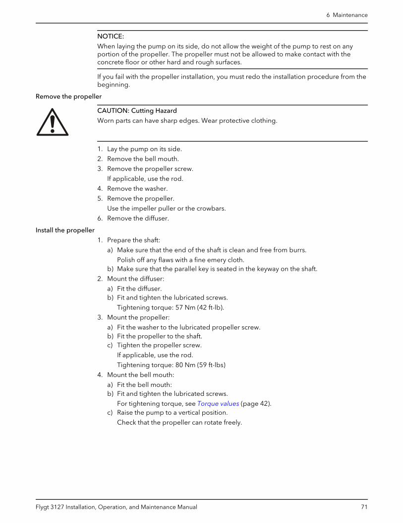
Remove the propeller
CAUTION: Cutting Hazard
Worn parts can have sharp edges. Wear protective clothing.
1. Lay the pump on its side.
2. Remove the bell mouth.
3. Remove the propeller screw.
If applicable, use the rod.
4. Remove the washer.
5. Remove the propeller.
Use the impeller puller or the crowbars.
6. Remove the diffuser.
Install the propeller
1. Prepare the shaft:
a) Make sure that the end of the shaft is clean and free from burrs.
Polish off any flaws with a fine emery cloth.b) Make sure that the parallel key is seated in the keyway on the shaft.
2. Mount the diffuser:
a) Fit the diffuser.b) Fit and tighten the lubricated screws.
Tightening torque: 57 Nm (42 ft-lb).
3. Mount the propeller:
a) Fit the washer to the lubricated propeller screw.b) Fit the propeller to the shaft.c) Tighten the propeller screw.
If applicable, use the rod.
Tightening torque: 80 Nm (59 ft-lbs)
4. Mount the bell mouth:
a) Fit the bell mouth:b) Fit and tighten the lubricated screws.
For tightening torque, see Torque values (page 42).c) Raise the pump to a vertical position.
Check that the propeller can rotate freely.
6 Maintenance
Flygt 3127 Installation, Operation, and Maintenance Manual 71
7 TroubleshootingIntroduction
DANGER: Electrical Hazard
Troubleshooting a live control panel exposes personnel to hazardous voltages. Electricaltroubleshooting must be done by a qualified electrician.
Follow these guidelines when troubleshooting:
• Disconnect and lock out the power supply except when conducting checks thatrequire voltage.
• Make sure that no one is near the unit when the power supply is reconnected.• When troubleshooting electrical equipment, use the following:
– Universal instrument multimeter– Test lamp (continuity tester)– Wiring diagram
7.1 The pump does not startDANGER: Crush Hazard
Moving parts can entangle or crush. Always disconnect and lock out power beforeservicing to prevent unexpected startup. Failure to do so could result in death or seriousinjury.
WARNING: Electrical Hazard
The permanent-magnet motor generates voltage when the shaft rotates, even if powersources are disconnected. Never perform any electrical work if the shaft could rotate.
NOTICE:
Do NOT override the motor protection repeatedly if it has tripped. Doing so may result inequipment damage.
Cause Remedy
An alarm signal has been triggeredon the control panel.
Check that:• The impeller rotates freely.• The sensor indicators do not indicate an alarm.• The overload protection is not tripped.
If the problem still persists:Contact the local sales and service representative.
The pump does not startautomatically, but can be startedmanually.
Check that:• The start level regulator is functioning. Clean or replace if necessary.• All connections are intact.• The relay and contactor coils are intact.• The control switch (Man/Auto) makes contact in both positions.
Check the control circuit and functions.
7 Troubleshooting
72 Flygt 3127 Installation, Operation, and Maintenance Manual

Cause Remedy
The installation is not receivingvoltage.
Check that:• The main power switch is on.• There is control voltage to the start equipment.• The fuses are intact.• There is voltage in all phases of the supply line.• All fuses have power and that they are securely fastened to the fuse
holders.• The overload protection is not tripped.• The motor cable is not damaged.
The impeller is stuck. Clean:• The impeller• The sump in order to prevent the impeller from clogging again.
Always state the serial number of your product, see Product Description (page 10).
7.2 The pump does not stop when a level sensor is usedDANGER: Crush Hazard
Moving parts can entangle or crush. Always disconnect and lock out power beforeservicing to prevent unexpected startup. Failure to do so could result in death or seriousinjury.
WARNING: Electrical Hazard
The permanent-magnet motor generates voltage when the shaft rotates, even if powersources are disconnected. Never perform any electrical work if the shaft could rotate.
Cause Remedy
The pump is unable to empty thesump to the stop level.
Check that:• There are no leaks from the piping and/or discharge connection.• The impeller is not clogged.• The non-return valve(s) are functioning properly.• The pump has adequate capacity. For information:
Contact the local sales and service representative.
There is a malfunction in the level-sensing equipment.
• Clean the level regulators.• Check the functioning of the level regulators.• Check the contactor and the control circuit.• Replace all defective items.
The stop level is set too low. Raise the stop level.
Always state the serial number of your product, see Product Description (page 10).
7.3 The pump starts-stops-starts in rapid sequenceCause Remedy
The pump starts due to back-flowwhich fills the sump to the start levelagain.
Check that:• The distance between the start and stop levels is sufficient.• The non-return valve(s) work(s) properly.• The length of the discharge pipe between the pump and the first non-
return valve is sufficiently short.
7 Troubleshooting
Flygt 3127 Installation, Operation, and Maintenance Manual 73
Cause Remedy
The self-holding function of thecontactor malfunctions.
Check:• The contactor connections.• The voltage in the control circuit in relation to the rated voltages on the
coil.• The functioning of the stop-level regulator.• Whether the voltage drop in the line at the starting surge causes the
contactor's self-holding malfunction.
Always state the serial number of your product, see Product Description (page 10).
7.4 The pump runs but the motor protection tripsDANGER: Crush Hazard
Moving parts can entangle or crush. Always disconnect and lock out power beforeservicing to prevent unexpected startup. Failure to do so could result in death or seriousinjury.
WARNING: Electrical Hazard
The permanent-magnet motor generates voltage when the shaft rotates, even if powersources are disconnected. Never perform any electrical work if the shaft could rotate.
NOTICE:
Do NOT override the motor protection repeatedly if it has tripped. Doing so may result inequipment damage.
Cause Remedy
The motor protection is set too low. Set the motor protection according to the data plate and if applicable thecable chart.
The impeller is difficult to rotate byhand.
• Clean the impeller.• Clean out the sump.• Check that the impeller is properly trimmed.
The drive unit is not receiving fullvoltage on all three phases.
• Check the fuses. Replace fuses that have tripped.• If the fuses are intact, then notify a certified electrician.
The phase currents vary, or they aretoo high.
Contact the local sales and service representative.
The insulation between the phasesand ground in the stator is defective.
1. Use an insulation tester. With a 1000 V DC megger, check that theinsulation between the phases and between any phase and ground is >5 megaohms.
2. If the insulation is less, then do the following:Contact the local sales and service representative.
The density of the pumped fluid is toohigh.
Make sure that the maximum density is 1100 kg/m3 (9.2 lb/US gal)• Change the impeller, or• Change to a more suitable pump• Contact the local sales and service representative.
There is a malfunction in the overloadprotection.
Replace the overload protection.
Always state the serial number of your product, see Product Description (page 10).
7 Troubleshooting
74 Flygt 3127 Installation, Operation, and Maintenance Manual

7.5 The pump delivers too little or no waterDANGER: Crush Hazard
Moving parts can entangle or crush. Always disconnect and lock out power beforeservicing to prevent unexpected startup. Failure to do so could result in death or seriousinjury.
WARNING: Electrical Hazard
The permanent-magnet motor generates voltage when the shaft rotates, even if powersources are disconnected. Never perform any electrical work if the shaft could rotate.
NOTICE:
Do NOT override the motor protection repeatedly if it has tripped. Doing so may result inequipment damage.
Cause Remedy
The impeller rotates in the wrongdirection.
• If it is a 3-phase pump, then transpose two phase leads.• If it is a 1-phase pump, then do the following:
Contact the local sales and service representative.
One or more of the valves are set inthe wrong positions.
• Reset the valves that are set in the wrong position.• Replace the valves, if necessary.• Check that all valves are correctly installed according to media flow.• Check that all valves open correctly.
The impeller is difficult to rotate byhand.
• Clean the impeller.• Clean out the sump.• Check that the impeller is properly trimmed.
The pipes are obstructed. To ensure a free flow, clean out the pipes.
The pipes and joints leak. Find the leaks and seal them.
There are signs of wear on theimpeller, pump, and casing.
Replace the worn parts.
The liquid level is too low. • Check that the level sensor is set correctly.• Depending on the installation type, add a means for priming the pump,
such as a foot valve.
Always state the serial number of your product, see Product Description (page 10).
7 Troubleshooting
Flygt 3127 Installation, Operation, and Maintenance Manual 75
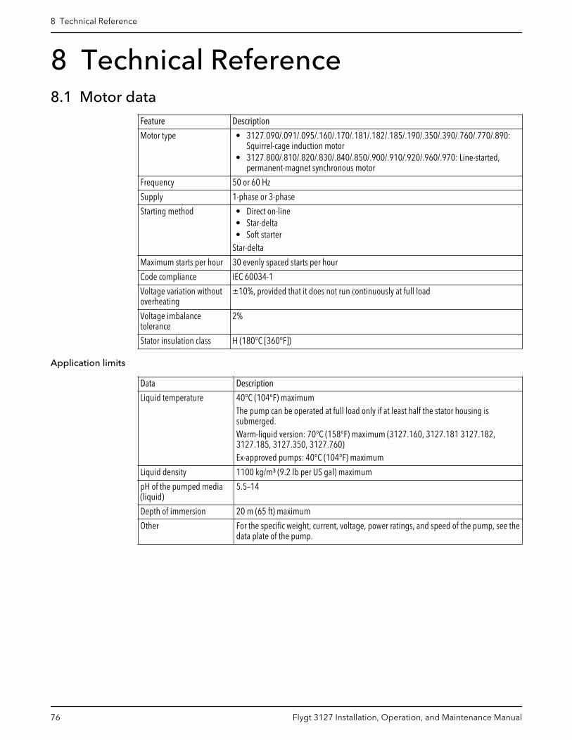
8 Technical Reference8.1 Motor data
Feature Description
Motor type • 3127.090/.091/.095/.160/.170/.181/.182/.185/.190/.350/.390/.760/.770/.890:Squirrel-cage induction motor
• 3127.800/.810/.820/.830/.840/.850/.900/.910/.920/.960/.970: Line-started,permanent-magnet synchronous motor
Frequency 50 or 60 Hz
Supply 1-phase or 3-phase
Starting method • Direct on-line• Star-delta• Soft starter
Star-delta
Maximum starts per hour 30 evenly spaced starts per hour
Code compliance IEC 60034-1
Voltage variation withoutoverheating
±10%, provided that it does not run continuously at full load
Voltage imbalancetolerance
2%
Stator insulation class H (180°C [360°F])
Application limits
Data Description
Liquid temperature 40°C (104°F) maximumThe pump can be operated at full load only if at least half the stator housing issubmerged.Warm-liquid version: 70°C (158°F) maximum (3127.160, 3127.181 3127.182,3127.185, 3127.350, 3127.760)Ex-approved pumps: 40°C (104°F) maximum
Liquid density 1100 kg/m³ (9.2 lb per US gal) maximum
pH of the pumped media(liquid)
5.5–14
Depth of immersion 20 m (65 ft) maximum
Other For the specific weight, current, voltage, power ratings, and speed of the pump, see thedata plate of the pump.
8 Technical Reference
76 Flygt 3127 Installation, Operation, and Maintenance Manual


Xylem |’zīləm|
1) The tissue in plants that brings water upward from the roots2) A leading global water technology company
We’re a global team unified in a common purpose: creating innovative solutionsto meet our world's water needs. Developing new technologies that will improvethe way water is used, conserved, and re-used in the future is central to our work.We move, treat, analyze, and return water to the environment, and we helppeople use water efficiently, in their homes, buildings, factories and farms. Inmore than 150 countries, we have strong, long-standing relationships withcustomers who know us for our powerful combination of leading product brandsand applications expertise, backed by a legacy of innovation.
For more information on how Xylem can help you, go to xyleminc.com
Refer to www.xylemwatersolutions.com/contacts/ for contact details of your local sales and servicerepresentative.
Xylem Water Solutions GlobalServices AB361 80 EmmabodaSwedenTel: +46-471-24 70 00Fax: +46-471-24 47 01http://tpi.xyleminc.com
Visit our Web site for the latest version of this documentand more information
The original instruction is in English. All non-Englishinstructions are translations of the original instruction.
© 2011 Xylem Inc
898582_8.0_en-US_2016-01_IOM.3127

17
Appendix 2 Civil Drawings


18
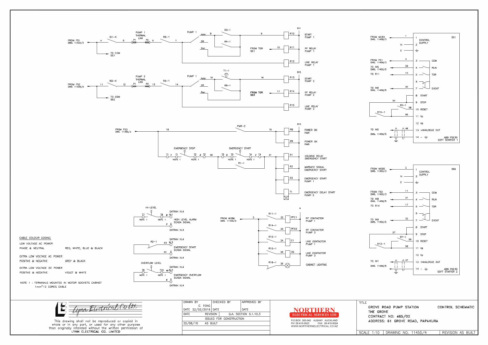
Appendix 3 Electrical Drawings


19
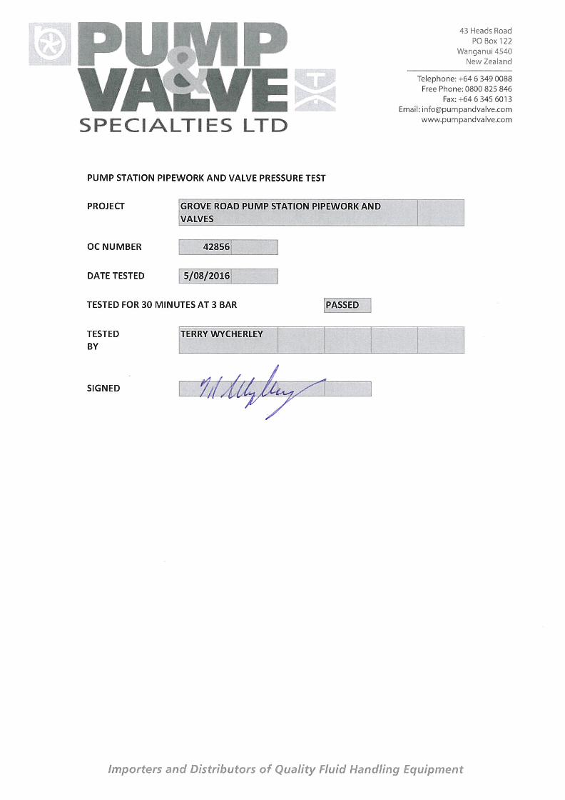
Appendix 4 Test Documentation and Certification


Page 12 8 November 2016
Our Ref: 3124460
NZ1-13217651-30 0.30
ATTACHMENT C

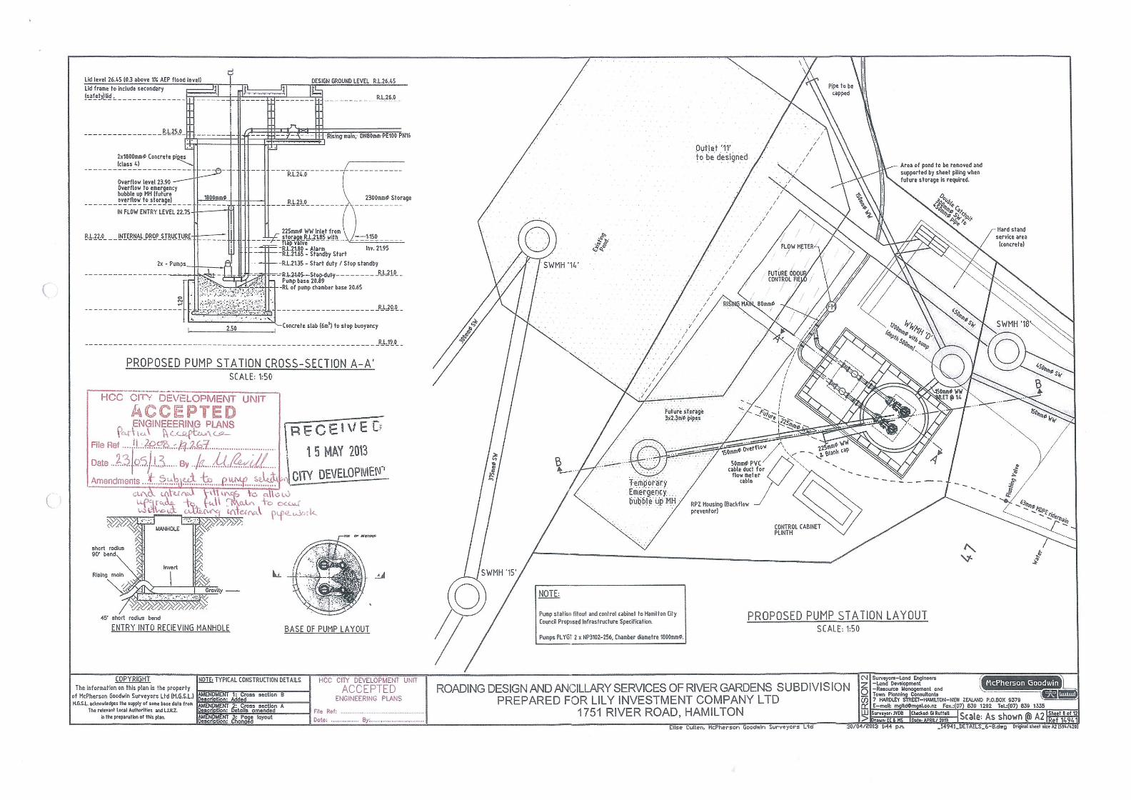
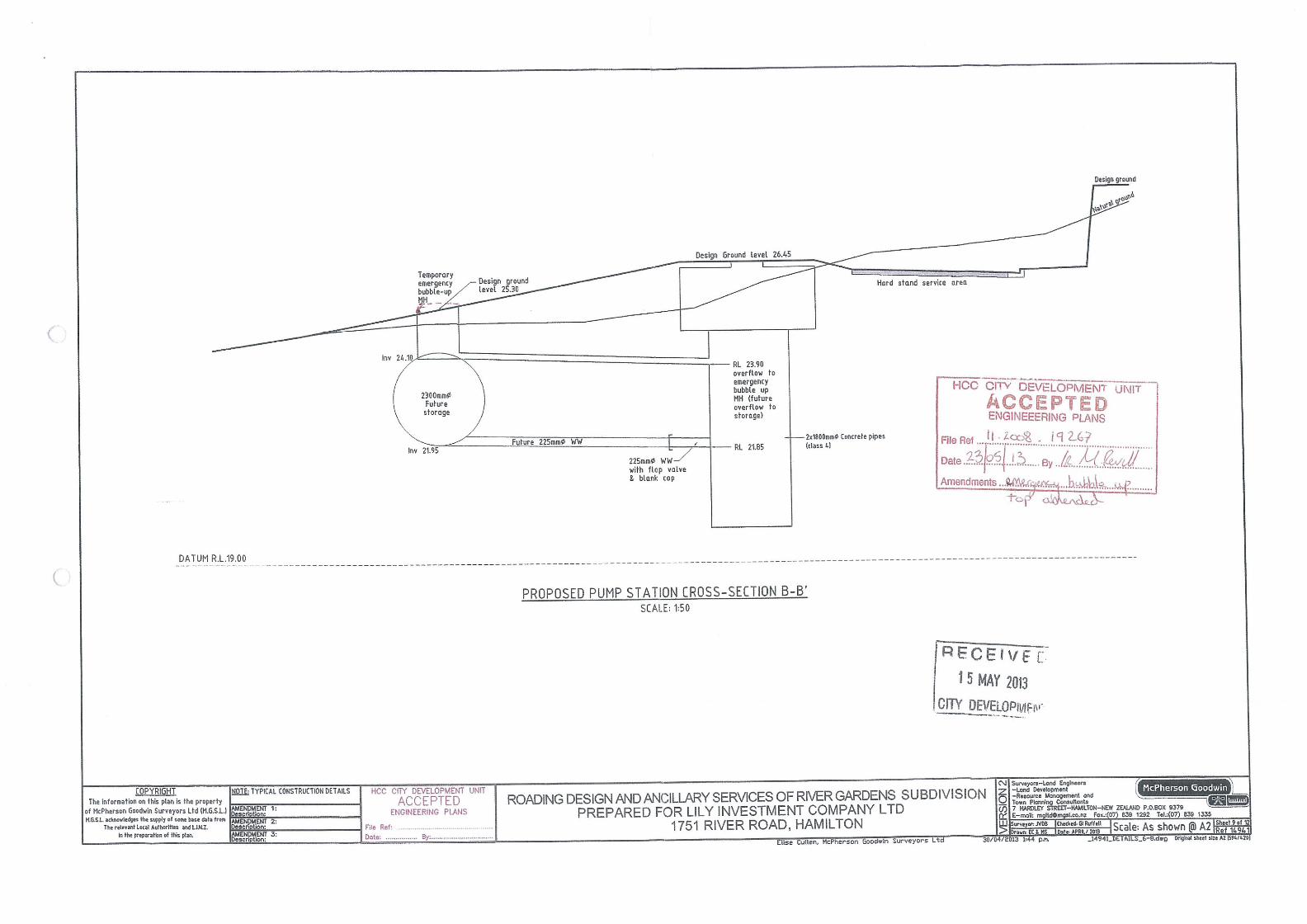
DATE: SCALE: CHK:DRN:FILE NAME:05.12.2009 N.T.S. CM2554/1 A.S.L. M.H.
Te Awamutu
STORMWATER RETENTION SYSTEMPROPOSED CROSS-SECTIONS & DETAILS
32
MANIFOLDS
1. THE INSTALLATION OF CHAMBERMAXX CHAMBERS SHALL BE IN ACCORDANCE WITH THE LATEST STORMWATER 360 INSTALLATION INSTRUCTIONS
2. THE CONTRACTOR IS ADVISED TO REVIEW AND UNDERSTAND THE INSTALLATION INSTRUCTIONS PRIOR TO BEGINNING SYSTEM INSTALLTION. CALL 0800STORMWATER OR VISIT www.stormwater360.co.nz TO RECIEVE A COPY OF THE LATEST STORMWATER INSTALLTION INSTRUCTIONS
3. CHAMBERS SHALL MEET THE DESIGN REQUIREMENTS AND LOAD FACTORS FOR HN- H072 HEAVY TRAFFIC LOADING
DESIGN SPECIFICATIONS
PLAN
ELEVATION
PLAN
ELEVATION
DIM
A
PIP
E I.D
.
PIPE I.D.
PIP
E I.D
.
PIP
E I.D
.
PIPE I.D.
PIP
E I.D
.
DIM
A
TO OUTLET CONTROL STRUCTURE
BED PERIMETER
B B
A
A
SECTION A-A
SECTION B-B
CHAMBERMAXX
PERFORATED UNDERDRAIN PIPE
DRAINCOIL OR SIMLAR
100Ø PERFORATEDHDPE UNDERDRAIN PIPEDRAINCOIL OR SIMLAR260mm FOUNDATION STONE
BENEATH CHAMBER
STONE BEDDING UNDER DRAINAGE PIPE
STONE BEDDING UNDER DRAINAGE PIPE NON-WOVEN GEOTEXTILE
KEY
1. RIGID OR FLEXIBLE PAVEMENT.2. GRANULAR ROAD BASE.3. WELL GRADED GRANULAR FILL. AS PER AS NZS 2566.4. FREE DRAINING ANGULAR WASHED STONE 20 - 40 mm PARTICLE SIZE. COMPACT TO AS NZS 2566.
400
MIN
.15
0 M
IN.
770
150
MIN
.
1435 (TYP)
PAVEMENT
1305(TYP)2 MIN. SPACING (TYP)
SUITABILITY OF SUBGRADETO BE VERIFIED BYENGINEER OF RECORD
SYNTEX GNP C1OR SIMILARNON-WOVENGEOTEXTILE
300 MIN.(TYP)
IMPERMEABLE LINERWRAPPED AROUND GEOTEXTILE
SYNTEX GNP C1 OR SIMILAR NON-WOVEN BETWEEN BASECOURSE AND POLYPROPYLENE LINER
SCOUR PROTECTION NETTING(TYP OF ALL INLET PIPES)
100MM SCHEDULE 40 PVC RISERWITH RING AND COVER (SUPPLIED BY OTHERS)
CONCRETE COLLAR(BY OTHERS)
2200 LAY LENGTH
(MID)
L
2440 LAY LENGTH(START)
START CHAMBER
MIDDLE CHAMBER
END CHAMBER
INSPECTION PORT (SUPPLIED BY OTHERS)
10 mm W X 40 mm HSLOTTED SIDEWALL OPENINGS
A
2250 LAY LENGTH
(MID)
1430
W
MANIFOLD TYP (HDPE PIPE)
SCOUR PROTECTION NETTING (2300 MM LONG TYP. WITH 300 MM OVER RUN AT END AND SIDES)
* SITE SPECIFIC DATA REQUIREMENTSFOR DETAILED DESIGN ASSISSTANCE
REFERENCE CHAMBERMAXX DYODS (DESIGN YOUR OWN DETENTION SYSTEM) SOFTWARE
AND CHAMBERMAXX STAGE STORAGE CALCULATOR @ WWW.STORMWATER360.COM
TOTAL REQUIRED STORAGE VOLUME (CM)
DEPTH TO INVERT BELOW ASPHALT (m)
LIMITING WIDTH (m)
LIMITING LENGTH (m)
POROUS STONE ABOVE CHAMBER (mm)
POROUS STONE BELOW CHAMBER (mm)
STONE POROSITY (0 TO 40%)
MANIFOLD SYSTEM DIAMETER (mm)
* PER ENGINEER OF RECORD
-
-
-
-
-
-
-
-
CHAMBERMAXX DESIGN DETAILS
FEATURE START CHAMBER
MIDDLE CHAMBER
END CHAMBER
OVERALL CHAMBER HEIGHT (mm) 770 770 770
OVERALL CHAMBER WIDTH (mm) 1305 1305 1305
ACTUAL LENGTH (mm) 2500 2300 2335
INSTALLED LAY LENGTHS (mm) 2440 2170 2250
CHAMBER STORAGE VOLUME (CM) 1.5 1.4 1.35
CHAMBER STORAGE PER LINEAR FOOT (CM/LM) 0.2 0.2 0.18
*MIN. INSTALLED CHAMBER VOLUME (CM) 2.2 2.1 2.1
*MIN. INSTALLED CHAMBER VOLUME PER LINEAR FOOT (CM/LM) 0.27 0.3 0.3
CHAMBER WEIGHT (Kn) 38 34.5 34.2
*150mm OF STONE ABOVE AND BELOW CHAMBER, 125mm CHAMBER SPACING AND 40 % POROSITY
1 23
4
127
SECTION A-A
716mm716mm 716mm
1433mm716mm
FOU
ND
ATI
ON
STO
NE
BE
NE
ATH
CH
AM
BER
260
mm
UNDERDRAIN
STANDARD AMNIFOLD COMPONENTSAVAILABLE DIAMETERS(mm)
TEE 305 381 457 610ELBOW 305 381 457 610DIM.A 1067 1067 1219 1219


ChamberMaxx is the latest in corrugated, open-bottom plastic arch systems designed to economically collect, detain, retain and infiltrate stormwater runoff. The chambers are injection-molded using structurally-efficient and corrosion-resistant polypropylene resin. With 2.15 m3 of available storage per chamber (including rock storage), ChamberMaxx is the most cost-efficient of its kind. In soakage applications, the ChamberMaxx system effectively recharges groundwater which can achieve Low Impact Design (LID) reduced discharge objectives. ChamberMaxx’s lightweight design has been extensively tested and exceeds New Zealand HN-HO 72 Heavy traffic loading standards.
ChamberMaxx™
CHAMBERMAXX BENEFITS SOAKAGE
Open bottomed plastic arch soakage chambers
• Features integral end walls for superior structural integrity, reduced costs, and fewer parts to handle during installation
• Modular configuration means flexible layout options
• Lightweight - each chamber weights approx 40Kg, and can be handlifted into place on site
• Exceeds USA (AASHTO HS-25), Australian and New Zealand (AS 5100.2, AS/NZS 2566 and HN-HO 72) heavy loading standard
• Effectively recharges groundwater which can achieve LID design requirements
• Low profile means it can be used on shallow sites
• Stormwater360 offers complete maintenance services for the UrbanGreen BioFilterChamberMaxx is a versatile lightweight plastic arch soakage system. Structural loading exceeds HN-HO 72 heavy traffic loading standard.
HOW DOES CHAMBERMAXX WORK? The open-bottom plastic chamber allows infiltration into surrounding soil, effectively achieving runoff reduction objectives for LID requirements. By utilising subsurface infiltration, space is preserved for development, runoff is reduced or eliminated and groundwater recharge can occur. The ChamberMaxx is ideal when you need to maximise storage capacity in a shallow footprint.
ChamberMaxx is modular and can be configured in various configurations depending on site layout and services. Installation is simple and as the chambers weigh less than 40 Kg each, they can be easily handled on site and dont require heavy lifting equipment. Void space between the chambers is filled with 40/20 crushed rock drainage aggregate providing load bearing capacity, as well as contributing to storage volume.
Detention and rainwater harvesting options are also available with the MaxxTank™ configuration using a heavy duty EPDM liner to surround the chambers and rock.
Structural load testing

WHY PRE-TREAT CHAMBERMAXX™ ?
Pre-treatment is recommended upstream of any soakage device. Fine sediments, litter and oil can clog soakage surfaces, reducing permeability affecting the rate of discharge. Maintenace of underground soakage systems can be diffcult and costly if required frequently. Correct pre-treatment can reduce overall maintenance costs and increase the quality of the water being recharged back into the groundwater system.
Stormwater360 offer several pre-treatment options depending on your site requirements. From Gross Pollutant Traps (GPT’s) to Media or Biofiltration options. Pre-treatment ensures longevity of your soakage system. For more information on pre-treatment, visit our website at www.stormwater360.co.nz
HEADER PIPE
STANDARD OPEN MID CHAMBER
INTEGRATED END WALL CHAMBER
INSPECTION PORT
STORMWATER 360PRE-TREATMENT HDS SYSTEMOR FILTER
Pallets of ChamberMaxx™ arches Backfilling chambers with rock Completed soakage system
Typical ChamberMaxx Layout
ChamberMaxx soakage below swale
www.stormwater360.co.nz


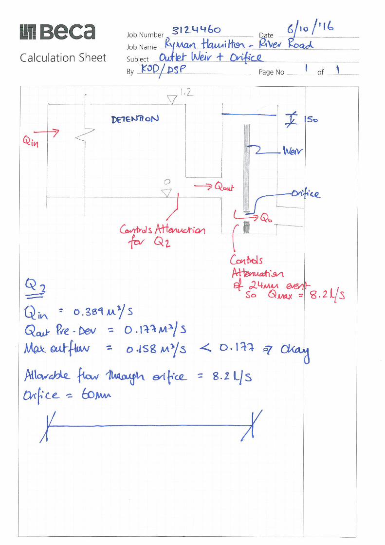
Design of Outlet System
Orifice (V&S 11.13)
Q=Cd*Ao*Sqr(2gh)
Allowable flow Q = 8.2 L/s
Discharge Coefficient Cd = 0.62 TP10-5-10
Effective Head h = 1.20
Ao = 0.0027 m2
Therefore dia. = 58.9 mm
use 60 mm dia.

Page 13 8 November 2016
Our Ref: 3124460
NZ1-13217651-30 0.30
ATTACHMENT D

1
Kealan Donagher
From: Jonathon Brooke <[email protected]>
Sent: Wednesday, 9 November 2016 4:38 p.m.
To: Kealan Donagher
Cc: Lawrence Njoku
Subject: RE: Ryman Retirement Village - River Road, Flagstaff, Hamilton
Attachments: 14158-E Channel Design.pdf; 14941 WRC Swale calcs.pdf; Lily River Rd Rev A 1.7.14.pdf; 200819267 - [5of6] Engineering Design -
Stormwater Calculations - Colebr....pdf; 200819267 - [4of6] Engineering Design - Stormwater Calculations - Colebr....pdf; 200819267 - [1of6]
Engineering Design - Application Letter - 1751 River ....pdf; 200819267 Stormwater and Amended Plan - 3 July 2008.pdf
Hi Kealan,
I am the development engineer looking after this consent.
I have gone through the file for the pond and found what information I could.
Hopefully this helps.
Cheers,
Jonathon
From: Kealan Donagher [mailto:[email protected]]
Sent: Wednesday, 9 November 2016 2:12 PM To: Fraser McNutt
Cc: Tony Denton
Subject: Ryman Retirement Village - River Road, Flagstaff, Hamilton
Hi Fraser, We are looking for any further information that may be in existence in relation to the stormwater pond at River Road. We are trying to answer some Section 92 queries(HCC S92 Ref: RH4284) but the information which we have on this is only partial (see attached) I was thinking there might have been an accompanying report describing the design parameters for the pond. Could you give me a call please to discuss? Tony Denton noted that you should be the first point of contact for queries of this nature. Regards, Kealan Donagher Associate - Civil Engineering
Beca
Phone +64 9 300 9000 Fax +64 9 300 9300
DDI: +64 9 308 0824 Mob: +64 27 239 0277
www.beca.com
www.LinkedIn.com/company/beca
NZ Workplace Health & Safety Supreme Award 2014 // Best overall contribution to improving workplace H&S
CIBSE Building Performance Awards 2015 // International Project of the Year - Christchurch International Airport Artesian Heating & Cooling System
NOTICE: This email, if it relates to a specific contract, is sent on behalf of the Beca company which entered into the contract. Please contact the sender if you are unsure of the contracting Beca company or visit our web page http://www.beca.com for further information on the Beca Group. If this email relates to a specific contract, by responding you agree that, regardless of its terms, this email and the response by you will be a valid communication for the purposes of that contract, and may bind the parties accordingly. This e-mail together with any attachments is confidential, may be subject to legal privilege and may contain proprietary information, including information protected by copyright. If you are not the intended recipient, please do not copy, use or disclose this e-mail; please notify us immediately by return e-mail and then delete this e-mail.


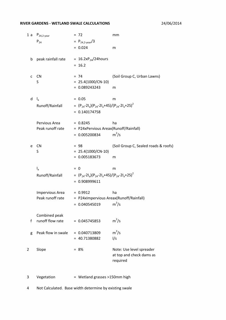
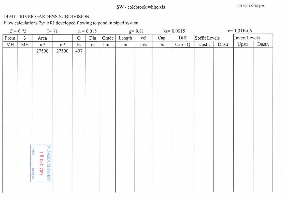
RIVER GARDENS - WETLAND SWALE CALCULATIONS 24/06/2014
1 a P24,2-year = 72 mm
P24 = P24,2-year/3
= 0.024 m
b peak rainfall rate = 16.2xP24/24hours
= 16.2
c CN = 74 (Soil Group C, Urban Lawns)
S = 25.4(1000/CN-10)
= 0.089243243 m
d Ia = 0.05 m
Runoff/Rainfall = (P24-2Ia)(P24-2Ia+4S)/(P24-2Ia+2S)2
= 0.140174758
Pervious Area = 0.8245 ha
Peak runoff rate = P24xPervious Areax(Runoff/Rainfall)
= 0.005200834 m3/s
e CN = 98 (Soil Group C, Sealed roads & roofs)
S = 25.4(1000/CN-10)
= 0.005183673 m
Ia = 0 m
Runoff/Rainfall = (P24-2Ia)(P24-2Ia+4S)/(P24-2Ia+2S)2
= 0.908999611
Impervious Area = 0.9912 ha
Peak runoff rate = P24xImpervious Areax(Runoff/Rainfall)
= 0.040545019 m3/s
f
Combined peak
runoff flow rate = 0.045745853 m3/s
g Peak flow in swale = 0.040713809 m3/s
= 40.71380882 l/s
2 Slope = 8% Note: Use level spreader
at top and check dams as
required
3 Vegetation = Wetland grasses >150mm high
4 Not Calculated. Base width determine by existing swale

5 T = 5 m
d = 0.2 m
Arectangle = Td
= 1
6
Flow velocity at
design rate = Q/A
= 0.040713809 m/s
= <0.8 m/s
7 t
Length Swale = Vt(60sec/min)
= 21.98545676 m
= <30m Note: Use minimum 30m
8 Ratio = L/W
= 6


CMG-348176-901-94-V1:cmg
Grantor
HEALTHCARE SHELF COMPANY NO.25 LIMITED
Grantee
HAMILTON CITY COUNCIL
Grant of easement or profit á prendre or creation or covenant
The Grantor, being the registered proprietor of the Servient Tenement(s) set out in Schedule A, grants to the Grantee
(and, if so stated, in gross) the easement(s) set out in Schedule A, with the rights and powers or provisions set out in the Annexure Schedule(s).
Schedule A Continue in additional Annexure Schedule if required.
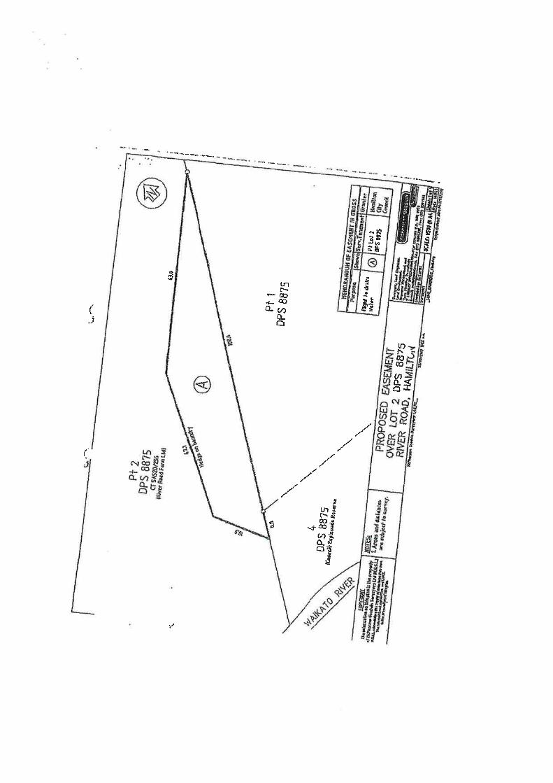
Purpose (nature and extent) of
easement, profit, or covenant Easement Land
Shown (plan
reference)
Servient Tenement
(Computer Register)
Dominant Tenement
(Computer Register) or in gross
Right to drain water
A on DP 491460
Part Lot 2 DPS 88575 CT SA52D/256
In Gross
Easements or profit á prendre rights and powers (including terms, covenants, and conditions)
Unless otherwise provided below, the rights and powers implied in specific classes of easement are those prescribed
by the Land Transfer Regulations 2002 and/or Schedule Five of the Property Law Act 2007.
The implied rights and powers are varied by the provisions set out in Annexure Schedule 1.
Easement instrument to grant easement or profit á prendre, or create land covenant Sections 90A and 90F, Land Transfer Act 1952
BKM-348176-901-16-V1:cmg
Annexure Schedule
Easement
1. Definitions 1.1 “Easement Facility” means pipes, conduits, open drains, pumps, tanks (with or without
headwalls), manholes, valves, surface boxes, other equipment suitable for that purpose (whether above or under ground), and anything in replacement or substitution.
“Easement Land” means that part of the Servient Land marked A on DPS 491460. “Grantee” means Hamilton City Council and any successor territorial authority having
jurisdiction over the Servient Land and includes the agents, employees, contractors, tenants, licensees, and other invitees of the Grantee.
“Grantor” means the registered proprietor of the Servient Land and includes the agents, employees, contractors, tenants, licensees, and other invitees of the Grantor. “Repair and Maintenance” in relation to an Easement Facility, includes the replacement of
the Easement Facility. “Servient Land” means the Servient Tenement identified in Schedule A of this instrument. 2. Grant of easement 2.1 The Grantor grants to the Grantee as an easement in gross forever the right for the Grantee
in common with the Grantor to gather, collect, concentrate and store on, over and under the Easement Land water in any quantity which shall from time to time accumulate in and from the Servient Land and other land and to drain, discharge and convey such water from such land.
3. Terms 3.1 The Grantee may from time to time enter into or upon the Servient Land by the most
practicable route with all necessary tools, vehicles and equipment and remain on the Servient Land and: (a) use any Easement Facility already situated on the Easement Land; (b) excavate the Easement Land and lay, install and construct any Easement Facility
reasonably required by the Grantee for the exercise of this grant on, through or under the Easement Land;
(c) inspect, maintain, repair, clean, dig up, alter, enlarge, renew or replace any Easement
Facility situated on the Easement Land; and (d) generally do anything necessary or convenient for the full exercise of the rights granted
by this instrument. 3.2 The Grantee agrees with the Grantor that when exercising any of its rights under this easement
the Grantee shall:
(a) cause as little damage as possible to the Servient Land and the occupiers of the Servient Land;

BKM-348176-901-16-V1:cmg
(b) restore the Servient Land as near as reasonably possible to its previous condition; and
(c) make good at the Grantee’s expense any damage done by the actions of the Grantee to buildings, erections and fences of the Grantor.
3.3 The Grantor shall not at any time do, permit, cause or suffer anything which may in any way
prevent or interfere with the full use and enjoyment by the Grantee of the rights created by this instrument or interfere with the efficient operation of any Easement Facility situated on the Easement Land and in particular (but without being limited to such matters) the Grantor will not:
(a) alter the surface of the Easement Land if such alteration will or is likely to impede or
alter the flow of water over the Easement Land; (b) build, construct, erect or place any building or structure (including any fence or gate)
on the Easement Land, except as designed and constructed or performed with prior written consent from and to the satisfaction of the Grantee;
(c) plant or grow any trees or shrubs on the Easement Land; and
(d) lay or maintain any pipes and cables for waste water, electricity, gas and telephone or
any other purpose through the Easement Land other than at a depth and location first approved by the Grantee.
4. Repair, maintenance and costs 4.1 The Grantee is responsible for arranging the repair and maintenance of the Easement Facility, and for the associated costs, so as to keep the Easement Facility in good order and to prevent it from becoming a danger or nuisance. 4.2 The Grantor or the Grantee must carry out at that party’s sole cost any repair and maintenance of the Easement Facility that is attributable solely to an act or omission by that party. 4.3 However, if the repair and maintenance of the Easement Facility is only partly attributable to an act or omission by the Grantor or Grantee, (a) that party must pay the portion of the costs of the repair and maintenance that is attributable to that act or omission; and (b) the balance of those costs is payable in accordance with subclause 4.1. 4.4 The parties responsible for maintenance under this clause must meet any associated requirements of the relevant local authority. 5. Default 5.1 If the Grantor or the Grantee does not meet the obligations implied or specified in this easement instrument, - (a) the party not in default may serve on the defaulting party written notice requiring the defaulting party to meet the specific obligation and stating that, after the expiration of 7 working days from service of the notice in default, the other party may meet the obligation: (b) if, at the expiry of the 7-working-day period, the party in default has not met the obligation, the other party may – (i) meet the obligation; and

BKM-348176-901-16-V1:cmg
(ii) for that purpose, enter the Servient Land: (c) the party in default is liable to pay to the other party the cost of preparing and serving the default notice and the costs incurred in meeting the obligation: (d) the other party may recover from the party in default, as a liquidated debt, any money payable under this clause. 6. Disputes 6.1 If a dispute in relation to this easement arises between the parties who have a registered interest under this easement, - (a) the party initiating the dispute must provide full written particulars of the dispute to the other party; and (b) the parties must promptly meet and in good faith try to resolve the dispute using informal dispute resolution techniques, which may include negotiation, mediation, independent expert appraisal, or any other dispute resolution technique that may be agreed by the parties; and (c) if the dispute is not resolved within 14 working days of the written particulars being given (or any longer period agreed by the parties), (i) the dispute must be referred to arbitration in accordance with the Arbitration Act 1996; and (ii) the arbitration must be conducted by a single arbitrator to be agreed on by the parties or, failing agreement, to be appointed by the President of the New Zealand Law Society. 7. General 7.1 No breach of the terms of this easement by the Grantee shall entitle the Grantor to cancel or
revoke this easement. 7.2 Any rights or immunities from liability or powers or remedies which the Grantee may have by
statute or at common law are not affected by this grant and the Grantee shall have those rights or immunities and may exercise those powers or remedies independently of this grant.
7.3 The exercise of any rights or powers conferred on the Grantee by this instrument shall not
entitle the Grantor to the payment of compensation under the provisions of any enactment or at law but nothing in this sub-clause 7.3 shall operate as a waiver of the Grantor’s rights or remedies if the Grantee breaches any provision of this instrument.