Embed Size (px)
Citation preview

1
Long Life Concrete Pavement Joint Performance
Joint Rehabilitation
Gary Fick, Trinity Construction Management Services, Inc. Representing the National CP Tech Center
Driving Forces for Concrete Pavement Joint Repairs
For states experiencing concrete pavement joint deterioration in cold weather, there are cost-effective repair methods available which can mitigate the damage and restore the existing pavement and the investment.

2
11.3
Treatment Selection Process
1. Conduct pavement evaluation.2. Determine joint distress causes.3. Identify potential treatments.4. Identify constraints.5. Develop feasible treatment strategies.6. Assess the life-cycle costs associated
with treatment strategies.7. Select preferred strategy.
Rehabilitation Strategies

3
Partial-Depth RepairsPartial-Depth Repairs
Removal and replacement of small, shallow areas of deteriorated PCC at spalled or distressed joints.
Introduction• Definition
• Distress limited to upper 1/2 of slab
• Existing load transfer devices are functional
• Cost $20 to $30 / ft.2
• Cost on Major Quantities of Longitudinal can be $12 - $20
• Cost on night work can be as high as $55 per square foot

4
Benefits
• Restores structural integrity
• Improves ride quality
• Extends the service life
• Restores a well-defined uniform joint sealant reservoir
Three Types of Partial Depth Repairs
Type 1 - Spots Repairs (SR) - Pay by Square Foot.Type 2 - Long Joint/Crack Repairs (LJCR) - Pay by Linear footType 3 - Bottom Half Repairs (BHR)

5
Good Candidate Projects
• Spalls caused by:- Incompressibles in joints
- Localized areas of weak material
- Joint deterioration
• Surface deterioration caused by:- Reinforcing steel too close to surface
- Poor curing or finishing practices
• Recommended evaluation procedures:- Distress surveys
- Sounding and cores from pavement
Poor Candidate Projects
• Spalls due to dowel bar misalignment
• Spalls at working cracks due to shrinkage, fatigue, or foundation movement
• Spalls due to D-cracking or reactive aggregate

6
Type 2 – Extended Length Repairs
• Longitudinal or transverse joints (Type 2A)
• Cracks (Type 2B) longer than 6 ft.
Joint (Long) Joint Crack (Transverse)
Type 2 – Extended Length Repairs
• Type 2A (Joints), the joint re-establishments typically by sawing
• Type 2B (cracks) the crack pressure relief is preformed joint material in the crack itself.
• Removal of the existing pavement is usually by milling
Type 2 (milled) Extended Length Repair

7
Material Selection for Partial-Depth RepairsPatch Material
• Material selection for partial-depth repairs depends on these factors:
- Allowable lane closure time (strength of material)
- Shrinkage Characteristics
- Coefficient of Thermal Expansion
- Ambient temperature
- Cost
- Size of repair
- Estimated performance
Partial Depth Repair MixesM-4WRIowa Mix
3U18Minnesota Mix
Cement 15.6% by volume 16.1% by volume
W/C 0.33 – 0.44 0.35
Coarse Agg. / Fin Agg. 50% Split62% by volume
50% Split59% by volume
WR Type E Type E
Coarse Aggregate Pea Gravel (100% passing 1/2”) or
3/8” Chips
100% passing 3/8”55”-95” passing No. 4
Air 6% by volume 6.5% by volume
8
Bonding (Grout) Agent
• Sand-cement grouts have proven adequate when used as bonding agents with concrete repair materials.
- 2 parts Type I cement
- 1 part water (may be more or less to develop a creamy consistency)
- 1 part sand
Construction Steps1. Repair dimension selection
2. Concrete removal
3. Repair area preparation
4. Joint preparation
5. Bonding agent application
6. Patch material placement
7. Curing
8. Diamond grinding (optional)
9. Joint sealing
9
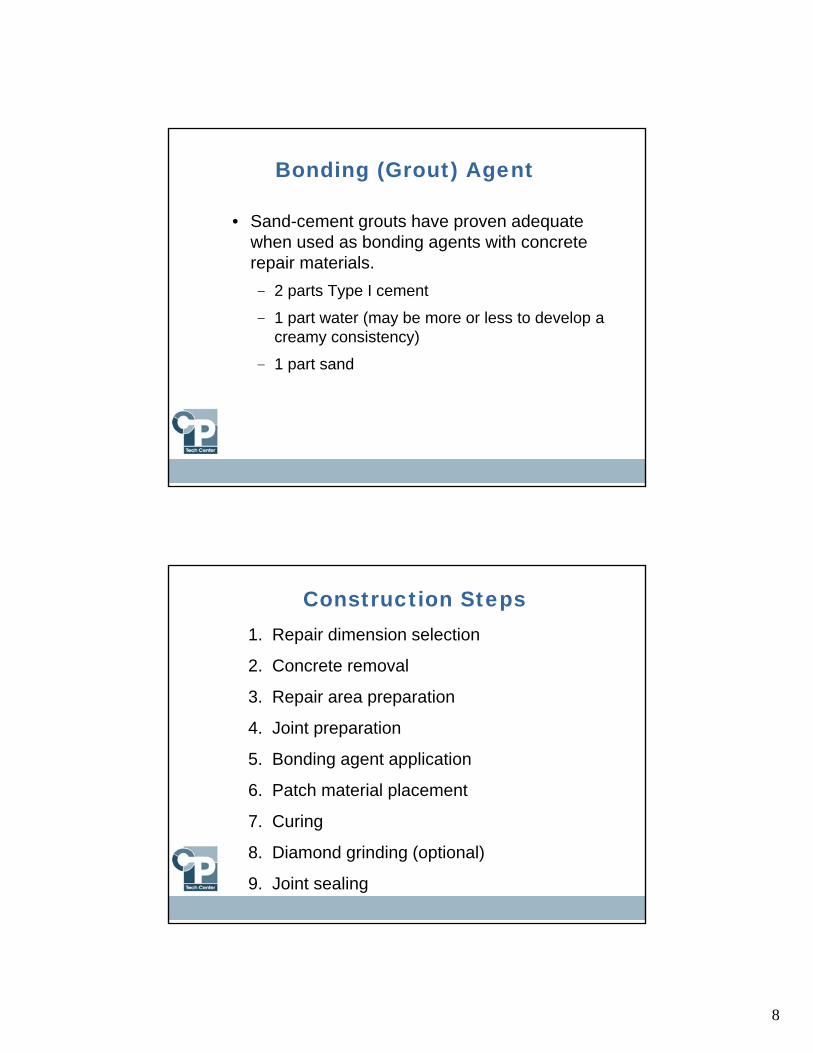
Repair Dimension Selection
Repair Dimension SelectionRecommendations
2 to 4 in (min) 2 to 4 in
(min)Patch areaSpall
LANE
Min. Patch Length 12 inMin. Patch Width 4 in
Single areas less than (6 in) 150 mm long or (1.5 in) 40 mm wide are not normally patched
10
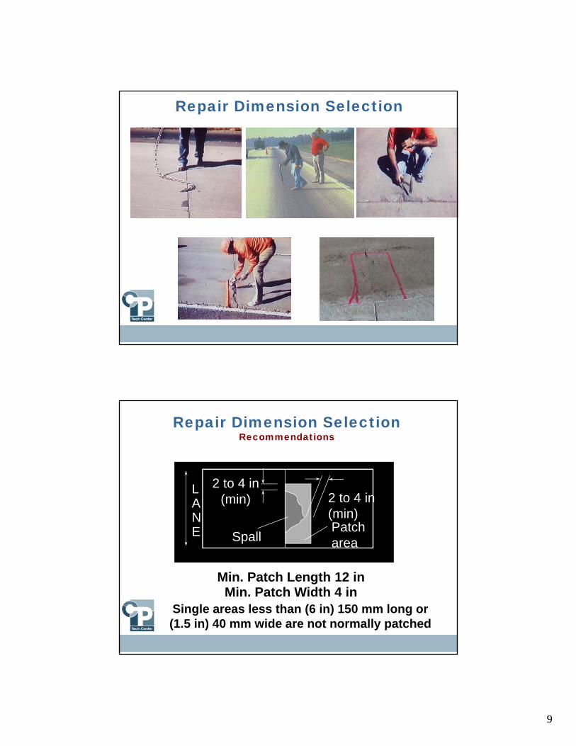
Partial-Depth Repair(TOP VIEW)
Boundary saw cuts min. 2 in. (50 mm) deep,3 in. (76 mm) outside distressed area.Overlap cuts at corners and approx. 1 in. (25mm) across joint.
Saw cut approx. 2 in. (51mm) away from joint forprotecting opposite face.
Saw cut skimming oppositejoint to provide cleanvertical face.
Concrete RemovalJackhammering
• Removal begins at center and extends outward
• Remove top 1/3 but no more
• Care not to fracture sound concrete
• Removal near joints should be done w/10-15 lb. hammer to avoid damage
• Operate hammer no greater than 35º

11
Compressible Insert
3 in. min.
Patch
Spall
Compressible insert
1 in.
Partial-Depth Repair
Partial-Depth Repair
Need for Compressible Insert
Point Bearing
Expansion Expansion
Joint Closure Debonding
Popout & Breakage

12
Milling Machine-V Head for Partial Depth Patch
• Weight – 9 Tons
• Little dust
• Removal rate 8 ft. / minute
Skid Steer for Milling Partial Depths• Best suited for corner spalls and
random cracks, it can maneuver better than the larger mills.
• Skid Steers weigh about 8000 pounds and can have removal rates of 2 – 3 feet per minute.
• Light weight skid steers can cause spalling at edges, but most minor spalls will be patched with concrete mix.
• It is easy to lift the front end off the ground during milling, but can be done with minor spalling.

13
Type 1 – Joint Mill and Removal
Milling along the joint or crackMilling perpendicular to the joint or crack
Type 2 – Joint Mill & Removal

14
Type 2 – Crack Mill and Removal
Type 2B Crack Milling
Rounded Milling (Type 1 & 2)
Sweeping Milled Area

15
Repair Area Preparation• Surface of the
repair area must be clean.
Sounding with hammer
Sandblasting to remove loose debris
Air Blasting for final cleaning
Bonding Agent Application• Cleaning the surface of the existing concrete
• Just prior to placement of the repair material, coat the surface with a sand-cement grout to ensure complete bonding of the repair material
• Mixed to the creamy consistency
• Placed immediately before the repair material, so the grout doesn’t set
Cement grout of Type 2A – Joint Repair
Cement grout of Type 3 – Bottom Half Repair

16
Placement of Compression Relief• To prevent failure, a strip of polystyrene or polyethylene
(wax board) compressible material is placed in the joint
• Has the ability to maintain its rigidity for the concrete placement.
• Place a foot on the cardboard during concrete vibration, so it does not float.
Concrete placement for Type 1 repair using waxed cardboard
Type 2B – Crack Repair
Screeding and Finishing• Screed the repair surface on each side of the compression
relief.• At least two passes should be made to ensure a smooth
repair surface.• Paint a sand-cement grout (the same grout as used for
bonding.• At the edges of the repair to impede delamination of the
patch.
Placement of grout at edge of partial-depth repair
17
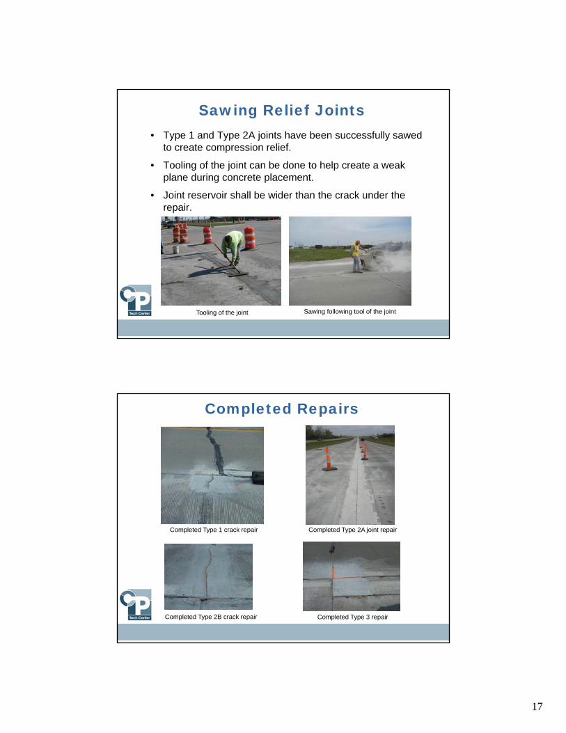
Sawing Relief Joints• Type 1 and Type 2A joints have been successfully sawed
to create compression relief.
• Tooling of the joint can be done to help create a weak plane during concrete placement.
• Joint reservoir shall be wider than the crack under the repair.
Tooling of the joint Sawing following tool of the joint
Completed Repairs
Completed Type 2A joint repairCompleted Type 1 crack repair
Completed Type 2B crack repair Completed Type 3 repair

18
Curing
• Prevent moisture loss
• White-pigmented curing compound commonly used (some require 1.5 to 2 times normal rate)
• Opening to traffic- Mix / temperature
dependent
- Common values: 2,000 to 3,000 psi
P.D.P. Have large surface areas in relation to their volumes (which can lead to rapid moisture loss)
Opening to Traffic
• Partial depth repair in upper half of pavement
• When bonded to existing pavement little or no tension in the patch
• Can open to traffic earlier (1,600 – 1,800 psi)

19
Examples of Long Lasting Partial Depth Repairs
20 year old Type 2A longitudinal and transverse partial depth repairs in
Hopkins, MN
Close up of partial depth patch in Hopkins, MN done in 1991 and
picture taken 2011
Full-Depth RepairsFull-Depth Repairs

20
Full-Depth Repair
• Purpose- Restore structure- Restore ride
• Used for- Joint/crack deterioration
Spalling (also below surface)
Cracking
- Broken slabs- Corner breaks Remove and Replace Concrete
1
2
3
Full-Depth Repair – KEY POINTS• Prior to paving, test the concrete mixture for strength,
strength gain and durability properties at the range of air temperature it will be placed in on the project
• Lay out patches and estimate material quantities as accurately
• Provide load transfer between all full-depth patches and the surrounding pavement.
• Use durable materials, a well-graded mix design, and a proper curing regiment for a long-lasting repair.
• .
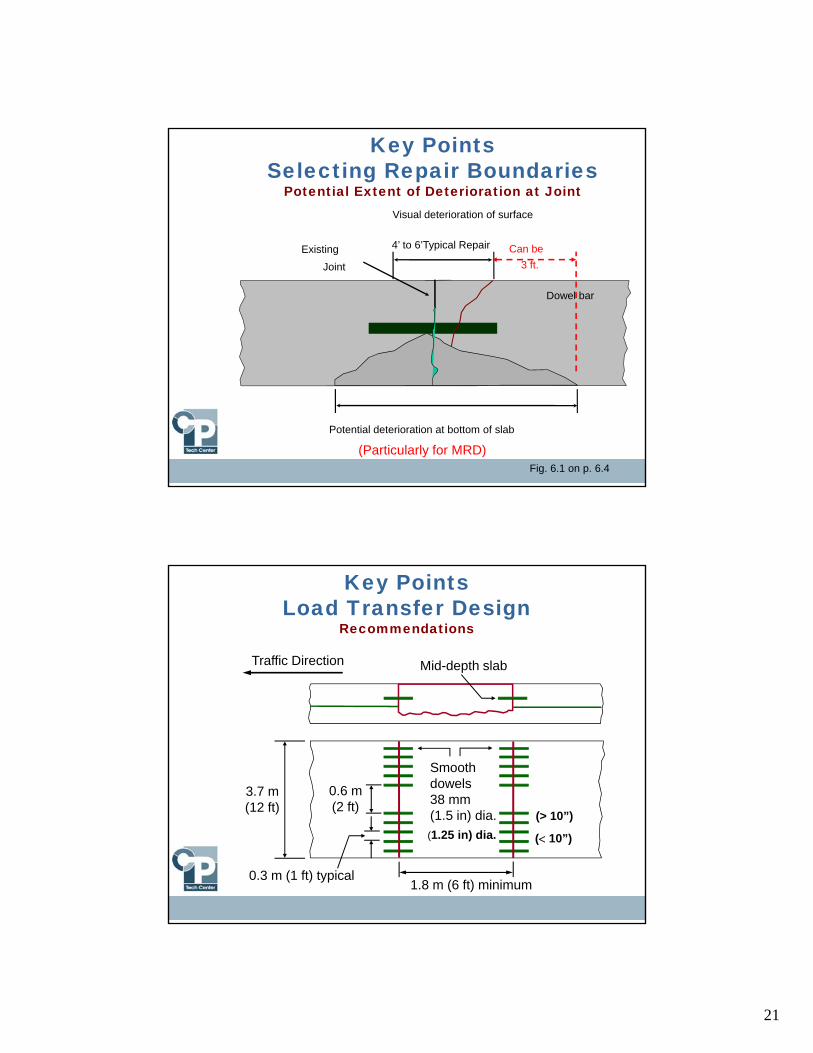
21
Potential deterioration at bottom of slab
Key Points Selecting Repair Boundaries
Potential Extent of Deterioration at Joint
Fig. 6.1 on p. 6.4
Visual deterioration of surface
Dowel bar
Existing
Joint 3 ft.
Can be
(Particularly for MRD)
4’ to 6’Typical Repair
Key Points Load Transfer Design
Recommendations
Smoothdowels38 mm (1.5 in) dia.
3.7 m(12 ft)
0.6 m(2 ft)
0.3 m (1 ft) typical1.8 m (6 ft) minimum
Mid-depth slabTraffic Direction
(1.25 in) dia. ( 10”)
(> 10”)

22
Key Points Repair Materials
• PCC mixes – Type 1-C mix (sometime accelerators)
• Rapid set cement (RSC) – 2 to 6 hrs.
• Regulated set portland cement (RSPC) –Initial set 2 to 30 min.
• Proprietary materials <4 hrs. opening (not recommended)
• Minimum opening strength 2000 to 2500 psi (most states)
Key Points Full-Depth Repair – Load Transfer
3
2
1 Inject Groutto Back of Hole
Twist one turnwhile pushingin dowel
Place groutretention disk to holdin grout (optional)

23
Full-Depth Repair - Opening
Slab Thickness
(in.)
Strength for Opening to Traffic (psi)
Repair Length < 10 ft Slab Replacements
Comp Flex Comp Flex
6 3000 490 3600 540
7 2400 370 2700 410
8 2150 340 2150 340
9 2000 275 2000 300
10+ 2000 250 2000 300
Joint Resealing

24
Trapped Moisture?• The longitudinal joints do not
open up as much because of the tie bars.
• Rehabilitation of existing pavement- Seal saw-cuts for both longitudinal and transverse joints if no outlet available
Joint and Crack Filling or Resealing
25
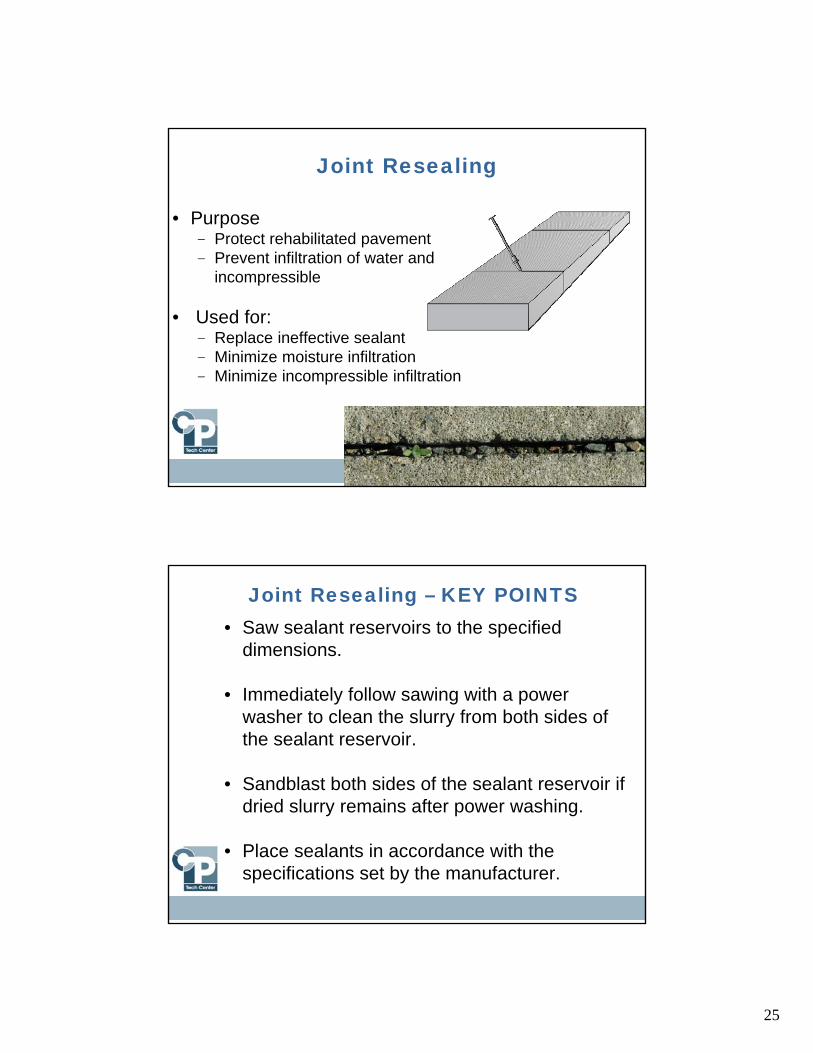
Joint Resealing
• Purpose- Protect rehabilitated pavement- Prevent infiltration of water and
incompressible
• Used for:- Replace ineffective sealant- Minimize moisture infiltration- Minimize incompressible infiltration
Joint Resealing – KEY POINTS• Saw sealant reservoirs to the specified
dimensions.
• Immediately follow sawing with a power washer to clean the slurry from both sides of the sealant reservoir.
• Sandblast both sides of the sealant reservoir if dried slurry remains after power washing.
• Place sealants in accordance with the specifications set by the manufacturer.

26
Joint and Crack Resealing
Backer Rod

27
Concrete OverlaysConcrete Overlays
Unbonded Overlays of Concrete Pavements
• Existing pavement serves as a subbase which must provide uniform support
• Because of this, unbonded overlays can be placed on pavements that are in poor condition
• Does not require extensive pre-overlay repairs to the existing pavement

28
Unbonded Overlays of Concrete Pavements
• Milling operation will remove a large portion of unsound concrete
• Mill the existing pavement full width and to a depth that removes the majority of deteriorated concrete
Unbonded Overlays of Concrete Pavements
• Removal of remaining loose material and leveling deteriorated joints areas with flowable mortar
- Partial Depth; flowable mortar
- Full Depth; Concrete

29
Unbonded Overlays of Concrete Pavements
• Placement of a separation layer (HMA or geotextile)
• Construction of an unbonded overlay
Unbonded Overlays Primary KeysThe keys to constructing successful unbonded overlays are:
• Minimal pre-overlay repairs
• Separator layer is important to isolate unbonded overlay from underlying pavement.
• If the separation layer is geotextile fabric heavy wrinkles in the fabric should be eliminated.
• Shorter joint spacing helps minimize curling and warping stresses; transverse joints should be placed at 6’ c/c or less.

30
Draining Interlayer
Curb Removed
Curb Not Removed
Questions?
Remember …
National CP Tech Centerhttp://www.cptechcenter.org