Embed Size (px)
Citation preview

2014-2011 Ford 6.2L & 6.8L GasF250-F550 Super Duty SEIC
Throttle #T500121
1930182; rev a


VMAC – Vehicle Mounted Air Compressors Toll Free: 1-888-241-2289 Fax: 1-250-740-3201 1
Installation Manual for VMAC Throttle Commander
2014-2011 Ford 6.2L & 6.8L Gas F250 - F550 Super Duty SEIC
Throttle Control # T500121
1.0 Preparing for Installation ........................................................... 3
2.0 Installing the Throttle Control Box ........................................... 5
3.0 Connecting the Wiring ............................................................... 5
3.1 Remote Pendant Connections (Accessory Part #3550707) ..... 6
4.0 Completing and Testing the Installation .................................. 6
4.1 Testing Throttles with Pendant Control ..................................... 7
5.0 Auxiliary Equipment Connection .............................................. 8
5.1 Single Speed Control ................................................................ 8
5.2 Multiple Speed Control .............................................................. 8
6.0 Adjusting the Throttle Control .................................................. 9
7.0 Operating the Pendant Controls ............................................. 10
7.1 Turning the Throttle On ........................................................... 10
7.2 Turning the Throttle Off ........................................................... 10
8.0 Troubleshooting ....................................................................... 11
9.0 Ordering Parts and Warranty .................................................. 13

VMAC – Vehicle Mounted Air Compressors Toll Free: 1-888-241-2289
Fax: 1-250-740-3201 2
Document 1930177 Installation Manual for VMAC Throttle Commander 2014-2011 Ford 6.2L and 6.8L Gas F250-F550 Super Duty SEIC Changes and Revisions
Version Revision Details Revised Approved Implemented
A Release ECN # 10-058 16 July 2010 SM 29 July 2010 18 Aug 2010
B ECN 12-021: UPDATES SAR 15 FEB 2012 MP 21Feb 2012 21 Feb 2012
C ECN 12-139 SAR 01 Oct 12 MH 15 Oct 2012 22 Oct 2012
D ECN 13-077 AH 17 Sep 2013 SM 26Sep2013 4 Oct 2013
Important Information
The information in this manual is intended for certified VMAC installers who have been trained in installation procedures and for people with mechanical trade certification who have the tools and equipment to properly and safely perform the installation. Do not attempt this installation if you do not have the appropriate mechanical training, knowledge and experience.
Follow all safety precautions and standard shop practices for mechanical work.
These instructions are a general guide for installing this throttle control on standard production trucks and do not contain information for installation on non-standard trucks. If you have difficulty with the installation, contact VMAC.
The VMAC warranty form is located at the back of this manual. This warranty form must be completed and mailed or faxed to VMAC at the time of installation for any subsequent warranty claim to be considered valid.
To order parts, contact your VMAC dealer. Your dealer will ask for the VMAC serial number, part number, description and quantity. To locate your nearest dealer, call 1-888-241-2289.
Copyright 2008 All trademarks used in this manual are the property of the respective copyright holder.
The contents of this manual may not be reproduced in any form without the express written permission of VMAC, 1333 Kipp Road, Nanaimo, BC V9X 1R3.
Printed in Canada
VMAC – Vehicle Mounted Air Compressors Toll Free: 1-888-241-2289 Fax: 1-250-740-3201 3
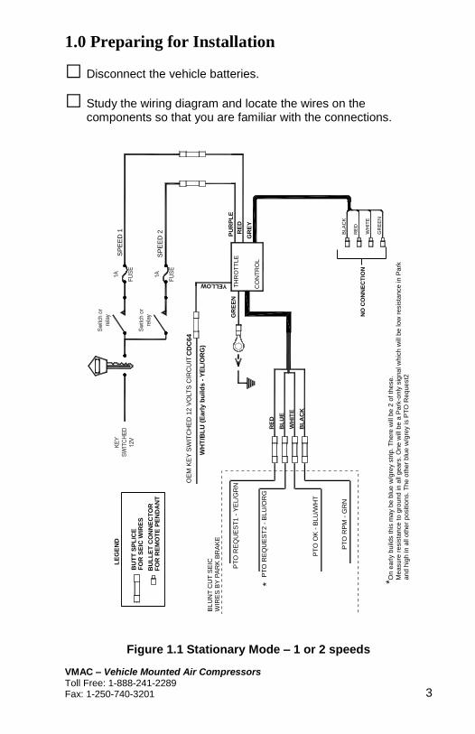
1.0 Preparing for Installation
□ Disconnect the vehicle batteries.
□ Study the wiring diagram and locate the wires on the components so that you are familiar with the connections.
RE
D
BLA
CK
WH
ITE
GR
EE
N
RE
D
WH
ITE
BL
AC
K
BL
UE
TH
RO
TT
LE
GR
EY
RE
D
CO
NT
RO
L
PU
RP
LE
YELLOW
GR
EE
N
SP
EE
D1
SP
EE
D2
OE
MK
EY
SW
ITC
HE
D12
VO
LT
SC
IRC
UIT
BL
UN
TC
UT
SE
ICW
IRE
SB
YP
AR
KB
RA
KE
PT
O O
K -
BLU
/WH
T
PT
O R
PM
- G
RN
PT
O R
EQ
UE
ST
2 -
BLU
/OR
G
PT
O R
EQ
UE
ST
1 -
YE
L/G
RN
* *On
early b
uild
s this
ma
y b
e b
lue w
/gre
y s
trip
. T
here
will
be
2 o
f th
ese.
Mea
su
re r
esis
tan
ce
to g
roun
d in a
ll g
ears
. O
ne w
ill b
e a
Park
-only
sig
nal w
hic
h w
ill b
e low
resis
tance in P
ark
and
hig
h in a
ll oth
er
positio
ns. T
he
oth
er
blu
e w
/gre
y is P
TO
Requ
est2
CD
C6
4
WH
T/B
LU
(E
arl
y b
uild
s -
YE
L/O
RG
)
BU
TT
SP
LIC
E
LE
GE
ND
BU
LL
ET
CO
NN
EC
TO
R
FO
R S
EIC
WIR
ES
FO
R R
EM
OT
E P
EN
DA
NT
NO
CO
NN
EC
TIO
N
Figure 1.1 Stationary Mode – 1 or 2 speeds

VMAC – Vehicle Mounted Air Compressors Toll Free: 1-888-241-2289
Fax: 1-250-740-3201 4
C
WA
LL
OR
FL
OO
RO
FC
AB
RP
M
OF
F
ON
TH
RO
TT
LE
OM
MA
ND
ER
GR
OM
ME
T
RE
D
BLA
CK
WH
ITE
GR
EE
N
WH
ITE
GR
EE
N
RE
D
BL
AC
K
RE
D
WH
ITE
BL
AC
K
BL
UE
TH
RO
TT
LE
GR
EY
RE
D
CO
NT
RO
L
PU
RP
LE
YELLOW
GR
EE
N
AC
CE
SS
OR
Y355
07
07
OE
MK
EY
SW
ITC
HE
D12
VO
LT
SC
IRC
UIT
BL
UN
TC
UT
SE
ICW
IRE
SB
YP
AR
KB
RA
KE
PT
O O
K -
BL
U/W
HT
PT
O R
PM
- G
RN
CD
C6
4
WH
T/B
LU
(E
arl
y b
uild
s Y
EL
/OR
G)
PT
O R
EQ
UE
ST
2 -
BL
U/O
RG
PT
O R
EQ
UE
ST
1 -
YE
L/G
RN
* * O
n e
arl
y b
uild
s th
is m
ay b
e b
lue
w/g
rey s
trip
. T
he
re w
ill b
e 2
of th
ese.
Me
asure
re
sis
tance t
o g
rou
nd
in a
ll ge
ars
. O
ne w
ill b
e a
Park
-only
sig
na
l w
hic
h w
ill b
e lo
w r
esis
tan
ce
in P
ark
and
hig
h in
all
oth
er
positio
ns. T
he o
ther
blu
e w
/gre
y is P
TO
Re
qu
est2
BU
TT
SP
LIC
E
LE
GE
ND
BU
LL
ET
CO
NN
EC
TO
R
FO
R S
EIC
WIR
ES
FO
R R
EM
OT
E P
EN
DA
NT
NO
CO
NN
EC
TIO
N
Figure 1.2 Stationary Mode – Remote Pendant

VMAC – Vehicle Mounted Air Compressors Toll Free: 1-888-241-2289 Fax: 1-250-740-3201 5
2.0 Installing the Throttle Control Box
□ Remove the dash panel below the steering column and tie-wrap the throttle control box under the dash.
3.0 Connecting the Wiring
□ Locate the bundle of blunt cut Customer Access/SEIC wire under the dash by the park brake.
HOOD
Bundle of blunt cut wires
Figure 3.1
.
□ Identify the correct wiring diagram for your application and connect the wires as indicated.

VMAC – Vehicle Mounted Air Compressors Toll Free: 1-888-241-2289
Fax: 1-250-740-3201 6
3.1 Remote Pendant Connections (Accessory Part #3550707)
□ Route the remote pendant cable into the cab through a suitable opening and connect the four colored wires on the pendant cable to the matching colored wires in the cable from the throttle control box. Make sure that the connectors are pushed together securely to make a good connection.
4.0 Completing and Testing the Installation
□ Check all wiring to ensure that it will not contact any hot or moving components and will not interfere with the operation of the vehicle. Secure all wiring with nylon ties and the supplied loom as required.
□ Connect the batteries. Place the vehicle in a safe operating position and block the wheels. Ensure that there are no people near the vehicle before beginning the test.
□ Temporarily route an 18 gauge test wire from the positive battery terminal into the cab. This wire will be used for the operational and safety tests.
□ Place the automatic transmission in PARK and engage the park brake. Start the vehicle engine and wait for the idle to stabilize and for engine temperature to reach normal operating range.
□ Momentarily activate the throttle by connecting the temporary wire from the battery positive post to the red speed 1 or purple speed 2 wire (located in the same bundle as the yellow power and green ground wires). The engine should start to idle up.
SEIC may not function initially on new vehicles. If this is the case, drive the vehicle for approximately 5 miles (8 KM). This should clear an “Alternative Calibration” that the vehicles start out with. For more details refer to the latest revision of Ford’s SVE Bulletin Q-173 @ www.fleet.ford.com/truckbbas
□ Release the park brake and momentarily activate as before. The engine should not idle up.

VMAC – Vehicle Mounted Air Compressors Toll Free: 1-888-241-2289 Fax: 1-250-740-3201 7
□ Apply the park brake and shift the automatic transmission into reverse with your foot on the service brake pedal. Momentarily activate as before. The engine should not idle up. Repeat the test in all gears.
□ Shift the transmission into Park and shut down the engine. 4.1 Testing Throttles with Pendant Control
□ Make sure that the “RPM” knob is turned down counter-clockwise, turn on the switch on the remote pendant, then slowly turn up the “RPM” knob clockwise. The engine should begin to idle up.
□ Turn the knob fully counter-clockwise. The engine should idle down.
□ Firmly apply the service brake pedal and hold it down.
□ Release the park brake and activate as before. The engine should not idle up.
□ Apply the park brake and shift the automatic transmission into reverse with your foot on the service brake pedal and activate as before. The engine should not idle up. Repeat the test in all forward gears.
□ Shift the transmission into Park and shut down the engine.
If the vehicle fails the test, check the wiring connections. If you require additional assistance, contact your local VMAC dealer or call VMAC at 1-888-241-2289 or 250-740-3200.
!

VMAC – Vehicle Mounted Air Compressors Toll Free: 1-888-241-2289
Fax: 1-250-740-3201 8
5.0 Auxiliary Equipment Connection
The throttle control has three possible speed settings by providing battery power to the red and purple wires. Default settings are:
Speed Selection Red wire Purple wire Factory setting
Off 0 Volts 0 Volts 0 RPM
Speed 1 12 Volts 0 Volts 1,250 RPM
Speed 2 0 Volts or 12 Volts* 12 Volts 1,800 RPM
* Speed 2 overrides Speed 1
Different methods for single speed connection are shown in Figure 5.1(switched) and Figure 5.2 (relayed). Multiple speed connections are a duplicate of the single speed method. 5.1 Single Speed Control
□ Connect the red wire from the throttle control through a suitable switch to an ignition activated 12-volt power source using an 18 gauge or heavier wire.
□ Coil and insulate the purple wire with tape.
□ Install a 1-amp inline fuse between the switch and the red wire. 5.2 Multiple Speed Control
□ Make the single speed connection using the red wire.
□ Connect the purple wire from the throttle control through a second switch to an ignition activated 12-volt power source using 18 gauge or heavier wire.
□ Install a 1-amp inline fuse between the switch and the wire.

VMAC – Vehicle Mounted Air Compressors Toll Free: 1-888-241-2289 Fax: 1-250-740-3201 9
Red
Purple
Speed 1 - Red
ThrottleController
Key switched12 Volts 1A fuse
Body builder
equipmentswitch
To PTO circuitor other equipment
This configuration uses a switch to turn on the throttle control at the same time as the bodybuilder equipment.
Figure 5.1
Red
Purple
Speed 1 - Red
ThrottleController
Key switched12 Volts 1A fuse
Body builder equipment switch To PTO circuit
or other equipment
This configuration uses a switch to activate arelay to turn on the throttle control at the same time as the body builder equipment.
87
86 85
30
87a
Figure 5.2
6.0 Adjusting the Throttle Control
□ Make sure that the switches or equipment supplying power to the throttle control are turned off.
□ Start the engine. Allow the engine to reach normal operating temperature.
□ Engine speed is adjusted by turning the screws on the throttle control. To increase the engine speed turn the screw clockwise, to decrease the engine speed turn the screw counter-clockwise.

VMAC – Vehicle Mounted Air Compressors Toll Free: 1-888-241-2289
Fax: 1-250-740-3201 10
□ To adjust SPEED 1, activate the throttle control using the control that is connected to the red wire. Adjust the RPM by turning the SPEED 1 screw.
□ To adjust SPEED 2, activate the throttle control using the control that is connected to the purple wire. Adjust the RPM by turning the SPEED 2 screw.
Never use the park brake or the transmission as an ON-OFF switch. When the engine is OFF, the throttle switch must be OFF. Do not reactivate the throttle switch until the engine has been restarted and the RPM has stabilized.
7.0 Operating the Pendant Controls Pendant control will override both Speed 1 and Speed 2.
7.1 Turning the Throttle On
□ Make sure that the “RPM” knob is turned down counter-clockwise before turning the throttle on to ensure the engine doesn’t rev past the desired operating speed.
□ With the engine running and the truck in “Park” with the park brake on, turn on the switch on the remote pendant.
□ Slowly turn up the “RPM” knob clockwise until the engine is at the desired speed.
7.2 Turning the Throttle Off
□ Turn the “RPM” knob fully counter-clockwise.
□ Turn off the switch on the remote pendant.
□ Shut off the engine.
!

VMAC – Vehicle Mounted Air Compressors Toll Free: 1-888-241-2289 Fax: 1-250-740-3201 11
8.0 Troubleshooting
Conditions that enable SEIC (all required)
Conditions that disable SEIC (any one required)
Park brake applied Park brake released Yes
Foot off of service brake Service brake depressed Yes
Vehicle in park (automatic trans) Vehicle taken out of park Yes
Foot off of clutch (manual trans) Clutch depressed Yes
Foot off of accelerator pedal Accelerator pedal depressed Yes
Vehicle is stationary (0 mph) Vehicle not stationary Yes
Brake lights are functional Brake light circuit disconnected Yes
Engine at a stable base idle speed
Yes
Transmission Oil Temperature Limit exceeds 240F
Yes
Engine Coolant Temperature (ECT) 40 Degrees F minimum for 2013MY and newer. 140 F minimum for 2012MY and older.
Engine Coolant Temperature Limit Yes
Catalyst Temperature Limit Yes
For further SEIC/PTO operation details, refer to the
latest revision of Ford’s SVE Bulletin Q-173 @
www.fleet.ford.com/truckbbas

VMAC – Vehicle Mounted Air Compressors Toll Free: 1-888-241-2289
Fax: 1-250-740-3201 12
Enable/Disable Conditions for SEIC Operation
OFFON
Steady OFF
OFFON
ONOFF
OFFON
OFFON
OFFON
Steady ON
"Triple Flash"
"Double Flash"
"Single Flash"
Standby mode
"Slow Blink" Standby state.
+12V applied to yellow wire.
Speed 1 requested, throttle disabled.
+12V applied to yellow wire.
+12V applied to red Speed 1 wire.
*A disable condition has occured.
Speed 2 requested, throttle disabled.
+12V applied to yellow wire.
**+12V applied to purple Speed 2 wire.
*A disable condition has occured.
Remote Pendant requested,
throttle disabled.
+12V applied to yellow wire.
**(Pendant turned on).
*A disable condition has occured.
Throttle on.
+12V applied to yellow wire.
**+12V applied to red Speed 1 wire,
and/or purple Speed 2 wire,
and/or Pendant turned on.
Throttle is off and has no power.OFF
0
5
6
7
4
Standby
"Single Flash"
Standby
"Double Flash"
Standby
"Triple Flash"3
2
1
ONOFF
ONOFF
ONOFF
Remote Pendant request.
+12V applied to yellow wire.
**(Pendant turned on).
Enable conditions have not been met.
Speed 2 request.
+12V applied to yellow wire
**+12V applied to purple Speed 2 wire.
Enable conditions have not been met.
Speed 1 request.
+12V applied to yellow wire.
+12V applied to red Speed 1 wire.
Enable conditions have not been met.
*Turn off Speed 1, Speed 2 and Remote Pendant to Restart Throttle.
** Speed 2 overrides Speed 1 and Remote Pendant overrides both Speeds 2 and 1.
CODE LED STATE DESCRIPTION
If you are unable to effectively troubleshoot operational problems, call your local VMAC dealer for technical support. To locate your nearest dealer call: 1-888-241-2289 or 250-740-3200.

VMAC – Vehicle Mounted Air Compressors Toll Free: 1-888-241-2289 Fax: 1-250-740-3201 13
9.0 Ordering Parts and Warranty
To order parts, contact your nearest VMAC dealer. Please quote the VMAC part number, the description and the quantity.
The VMAC warranty form must be completed and mailed or faxed to VMAC at the time of installation for any subsequent warranty claim to be considered valid.

This page intentionally left blank

VMAC – Vehicle Mounted Air Compressors Toll Free: 1-800-738-8622
Fax: 1-250-740-3201
VMAC Product Warranty Registration This form must be fully completed and returned to VMAC at the time of installation. Warranty will be void if this form is not received by VMAC within 30 days of installation. VMAC Dealer Information
Company Name: ______________________________________ City: _____________________ State/Prov:______________
Installer Information
Company Name: ______________________________________ City: _____________________ State/Prov:______________ Installation Date: _____/_____/_____ Day Month Year
Owner Information
Company Name: ______________________________________ Address: ____________________________________________ City: _____________________ State/Prov:______________ Zip/Postal: ________________ Phone #: (____)____-_____
Vehicle Information
Year: ____________________ Make: _________________ Vehicle Identification Number: ___________________________ Unit #: ___________________
Product Information
System Identification Number: V _ _ _ _ _ _ _ _ _ _ _ _ _ _ _ _ _ Compressor Serial Number: P_ _ _ _ _ _ _ _ _ _ _ _ _ _ _ _ _ _ _ Throttle Control Serial Number: _ _ _ _ _ _ _ _ _ _ _ _ _ _ _ _ _ _

This page intentionally left blank


Manufactured by
PH 250-740-3200FX 250-740-3201TF 1-800-738-8622
1333 Kipp Road, Nanaimo, BC, V9X 1R3 Canadawww.vmacair.com