Embed Size (px)
Citation preview

60 GHz Outdoor Urban Measurement Studyof the Feasibility of Multi-Gbps
mm-Wave Cellular NetworksLjiljana Simic, Nikos Perpinias and Marina Petrova
Institute for Networked Systems, RWTH Aachen UniversityKackertstrasse 9, D-52072 Aachen, GermanyE-mail: {lsi, npe, mpe}@inets.rwth-aachen.de
Abstract—Future 5G cellular networks are expected to exploitthe abundant spectrum resources of the millimeter-wave (mm-wave) bands to satisfy demand for multi-Gbps mobile linksanticipated by exponential data traffic growth. However, giventhe directional nature of mm-wave links, the feasibility of mm-wave mobile networks is critically dependent on efficient antennabeamsteering and a rich inventory of strong LOS (line-of-sight)and NLOS (non line-of-sight) paths from effective reflectors inthe urban environment. In this paper we report results fromdetailed angular measurements of 60 GHz links at an exampleoutdoor pico-cellular site in a mixed-use urban environmenttypical of European cities. Our work is the first to systematicallyanalyze the beamsteering requirements of future mm-wave cel-lular networks based on real measurements. Our results revealthat the urban environment provides substantial opportunitiesfor multi-Gbps mm-wave connectivity, but that the availabilityof strong LOS/NLOS links is highly location and orientation-specific. Our results also show that high speed mm-wave linksare very sensitive to beam misalignment. This has importantimplications for practical mm-wave cellular network design: (i)high-precision beamsteering is required to maintain stable datarates even for quasi-stationary users; and (ii) providing seamlesshigh speed service in mobility scenarios will be extremelychallenging. Our results thus cast doubt on whether outdoormm-wave cellular deployments will be feasible in practice, giventhe high network control overhead of meeting such stringentbeamsteering requirements.
I. INTRODUCTION
The plentiful spectrum resources available at the millimeter-wave (mm-wave) bands are widely expected to be a keymeans of addressing the challenges of exponential mobile datagrowth – and the resulting “spectrum crunch” in the currentlicensed microwave bands – in future 5G cellular networks [1],[2]. However, outdoor propagation at mm-wave frequenciesis challenging. Firstly, it relies on the existence of LOS(line-of-sight) or strong reflected NLOS (non line-of-sight)transmission paths [3]. This is in contrast to traditional cellularnetworks where diffraction is a major propagation mechanismfacilitating coverage in NLOS environments. Namely, linkopportunities in mm-wave networks are far more dependenton the idiosyncratic urban layout at a cell site than in existingcellular deployments. Secondly, overcoming the inherentlyhigh path loss at mm-wave necessitates the use of directionalantennas. Accordingly, the added complexity of performing
beamsteering to establish and maintain strong LOS/NLOSlinks for mobile users is likely to impose a significant controland signalling overhead in mm-wave cellular networks.
Detailed directional characterization of mm-wave connec-tivity is thus crucial for gaining insight into the beamsteeringrequirements and opportunities of outdoor mm-wave net-works, but is largely unaddressed in the existing literature [3].The seminal outdoor measurements conducted by Rappaportet al. [4] using a wideband sliding correlator channel sounder,at 28 GHz [5] and 73 GHz [6] in New York City and at 38 GHzand 60 GHz [7] in Austin, have shown that mm-wave links arepossible up to a cell radius of 200 m. In [5], the authors presentillustrative AoA (angle of arrival) results, in the azimuthplane only, demonstrating that on average three main “lobes”exist corresponding to distinct LOS/NLOS paths. However,the work of Rappaport et al. has otherwise largely focusedon fundamental mm-wave propagation channel modelling,including time-domain characterization and empirically fittingaverage LOS/NLOS path loss exponents to provide initialestimates of the coverage achievable with mm-wave links.
By contrast, in this paper we take a system-level, networkdesign perspective to assessing the feasibility of mm-wavecellular networks. We address the key question of: how strin-gent are the beamsteering requirements in urban mm-wavenetworks for seamless multi-Gbps mobile data provisioning?We report results from a 60 GHz outdoor urban measurementstudy in the centre of a typical European city, and presentan analysis of the fine-grained angular characteristics of mm-wave links at our example pico-cellular site. Our results revealthat the urban environment considered provides significantmulti-Gbps link opportunities, but that high-precision beam-steering is needed to maintain a stable high data rate, evenfor a quasi-stationary user. Namely, our results suggest thatthe beamsteering complexity may be prohibitively high tomake mm-wave deployments attractive in practice for outdoormobile environments.
To the best of our knowledge, our work is the first tosystematically study the beamsteering requirements for futuremm-wave cellular networks based on real outdoor urbanmeasurements. We are also the first to report detailed measure-ments for a 60 GHz cellular-like outdoor urban deployment:
arX
iv:1
603.
0258
4v1
[cs
.NI]
8 M
ar 2
016

TABLE ITX ORIENTATIONS & LOS DISTANCE PER RX LOCATION
RXloc.
# TXorient.†
φtx θtx dtx−rx
(3D)
A 10× 7 15◦:5◦:55◦, 95◦ −5◦:−5◦:−35◦ 28 m
B 7× 4 55◦, 105◦:10◦:155◦ −5◦:−10◦:−35◦ 21 m
C 7× 4 55◦:10◦:115◦ −5◦:−10◦:−35◦ 11 m
D 6× 4 35◦:10◦:65◦, 85◦, 95◦ −5◦:−10◦:−35◦ 19 m
E 6× 4 55◦, 75◦:10◦:115◦ −5◦:−10◦:−35◦ 19 m
F 4× 4 60◦:10◦:90◦ −5◦:−10◦:−35◦ 24 m
G 7× 4 15◦:10◦:65◦, 95◦ −5◦:−10◦:−35◦ 28 m
†At each TX orientation, measurements recorded at 100× 16 RXorientations, φrx = −176.4◦:3.6◦:180◦, θrx = −28.8◦:3.6◦:25.2◦.
only peer-to-peer measurements were reported at 60 GHzin [7], the Berlin measurements in [8] solely characterizedLOS links with omnidirectional antennas, and [9] consideredonly conceptual networking aspects. Moreover, existing mm-wave outdoor measurements [4], [8] have been in urbanenvironments characteristic of very large cities and CBD-likeurban layouts, with wide streets and modern buildings madeof relatively homogeneous materials (typically highly reflec-tive, e.g. concrete and glass). We instead consider a mixed-use urban environment with heterogenous building types andmaterials, typical of most European cities, and quantify theextent of reflected NLOS opportunities with respect to theurban layout and materials. Finally, given the general lackof experimental studies in mm-wave networking, we believeour methodology will also be of interest to the emergingexperimental indoor 60 GHz research community [10], [11].
The rest of this paper is organized as follows. Section II de-scribes our measurement setup and methodology. In Section IIIwe present and analyze our measurement results. Section IVconcludes the paper.
II. MEASUREMENT SETUP & METHODOLOGY
Our measurement campaign was conducted over ten daysin October 2015, in a busy mixed-use urban area (Fig. 1a)in the centre of the mid-sized German city of Aachen. As istypical of urban environments in many European cities, thearea consists of densely built-up residential buildings of 3–5stories, with retail outlets and restaurants on the ground floor.The transmitter was mounted at the window of a third floorapartment at a height of approximately htx = 11 m from theground, overlooking a busy street and opposite an intersectionwith a one-way side street, as shown in Figs. 1a and 2c.We emphasize that the transmitter height and location arerepresentative of where a mm-wave base station might bedeployed. The measurement area contains a typically het-erogenous mix of building materials, e.g. shop-window glasswith metal frames, metal doors, rough and smooth brickwork
and concrete. This allowed us to explore a large variety ofreflection opportunities from the surrounding building envi-ronment for potential NLOS transmission paths; the majorreflecting materials enabling NLOS links (as observed in ourmeasurements) are indicated in Fig. 1. The receiver, shown insitu in Fig. 2d, was at a height of approximately hrx = 1.8 mfrom the ground and placed at the seven different receiverlocations A–G in Fig. 1a.
The future deployment of mm-wave cellular networks ispreconditioned on the existence of electronically steerableon-chip phased antenna arrays. However, these are not yetavailable – neither commercially, nor for system-level researchexperiments. Therefore, in order to emulate beamsteering of amm-wave antenna array, in our measurements we used direc-tional horn antennas and mechanical 3D steering platforms,whereby we set the antenna main lobe orientation by thecombination of the azimuth angle φ on the horizontal planeand the elevation angle θ on the vertical plane. A uniquepair of transmitter and receiver antenna orientation may thusbe expressed as the 4-tuple (φtx, θtx, φrx, θrx). We steeredthe transmit antenna manually using the platform shown inFig. 2c, whereas at the receiver we used the custom 3D-printedplatform housing the antenna shown in Fig. 2d with a con-troller and stepper motors (3.6◦ resolution) to automaticallystep through receiver orientations.
At each individual receiver location, measurements wereconducted for multiple (azimuth × elevation) combinationsof transmitter antenna orientation1, as specified in Table I. Inturn, for each considered transmitter orientation, we measuredthe received signal strength (RSS) for 100×16 (azimuth × el-evation) combinations of receiver antenna orientation. Theangular granularity of our measurement sweeps is thus sig-nificantly higher than earlier works; e.g. the 28 GHz AoAmeasurement results in [5] were based on sweeps over only(3× 1× 36× 3) combinations of (φtx, θtx, φrx, θrx), whereasthe 60 GHz measurements in [7] searched over the azimuthand elevation planes for substantial signals randomly ratherthan systematically. We note that each of our single complete3D receiver antenna sweeps takes approximately 15 min-utes, which represents a significant measurement time-budgetchallenge, given all combinations of considered transmitterorientations and receiver locations. Consequently, we chose thegranularity of transmitter antenna steering to be comparable tothe antenna beamwidth of 10◦, whereas the finer granularityof steering at the receiver was chosen to collect detailedangular link measurements with respect to the surroundingurban building structures and materials, thus yielding insightinto the beamsteering requirements of urban mm-wave cellularnetworks.
Figs. 2a and 2b detail our mm-wave measurement setup atthe transmitter and receiver side, respectively. At the transmit-ter, Agilent E4438C ESG vector signal generator is used to
1We considered only TX angles which may result in a LOS or reflectedNLOS link, given the geometry of the urban environment at each RX location;e.g. for RX G, 65◦ < φtx < 95◦ was omitted as no reflected NLOS path isfeasible if the TX is pointing down the side street.

D
F
BA
G
E
0 5 m
0o Az (Tx)C
TX
(a) all RX locations
RX-A
TX
LOS
NLOS 3
NLOS 1
NLOS 2
glassmetal/glassother
(b) RX location A
RX- Bcar
TX
LOS
NLOS 1
NLOS 3NLOS 2
NLOS 4
glassmetal/glassother
(c) RX location B
NLOS 1 NLOS 2
RX- C
TXglassmetal/glassother
(d) RX location C
RX- D
car
TX
LOS
NLOS 1
NLOS 3
NLOS 2
glassmetal/glassother
(e) RX location D
RX- E
TX
LOS
NLOS 1NLOS 3
NLOS 2
glassmetal/glassother
car
NLOS 4
(f) RX location E
RX- Fcar
TX
LOS
NLOS 1
glassmetal/glassother
(g) RX location F
RX- G
NLOS 1
TXglassmetal/glassother
(h) RX location G
Fig. 1. Maps illustrating the mixed-use urban measurement study area, showing (a) the locations of the transmitter (TX) and receiver (RX)and (b)-(h) for each RX location the azimuth direction of major LOS/NLOS links found w.r.t. surrounding building layout and materials.
fIF= 1.5 GHz fRF= 61.5 GHz
IF signal generator mmWave upconversion
SMA cable WR‐15
Manual 3D antenna steering
SiversIMA FC1005V/00
Agilent E4438C ESG vector
signal generator
25 dBi standard gain horn antenna
Mechanically rotated platform
(a) TX block diagram
Automated 3D antenna steering
WR‐15
mmWave RF to spectrum analyzer
SMA cable Ethernet
USB
25 dBi standard gain horn antenna
Agilent N9030A spectrum analyzer
Measurement laptop
Arduino controllerStepper motor ‐
azimuth
Stepper motor ‐ elevation
Rotating platform
Diplexer OML
DPL.313B fRF= 61.5 GHz
fIF= 300 MHz
fLO= 3.75 to 14 GHz
fIF, fLOAgilent 11970V external mixer
(b) RX block diagram
RX-F
MECHANICAL 3D STEERING PLATFORM
SiversIMA FC1005V/00
HORN ANTENNA
(c) TX in situ, looking down on RX location F
HORN ANTENNA
MEASUREMENT LAPTOP
SPECTRUM ANALYSER
BATTERIES
AUTOMATED 3D STEERING PLATFORM
(d) RX in situ at location A
Fig. 2. Measurement set-up, showing transmitter (TX) and receiver (RX) block diagrams and annotated in situ photographs.
generate a continuous wave signal2 of Ptx,IF = −18 dBmat the intermediate frequency of fIF = 1.5 GHz, whichis then fed via a low-loss SMA cable to the SiversIMAFC1005V/100 [12] mm-wave upconverter. The output of themm-wave upconverter is a Ptx,RF = 5 dBm signal at thecentre frequency of fRF = 61.5 GHz, which is finally fed
2We emphasize that we use narrowband power measurements without lossof generality, as we are interested only in measuring expected RSS (i.e. pathloss) for a given TX/RX orientation, and not in time-domain characterizationof the mm-wave channel as in the channel sounding measurements of [4], [8].
via the WR-15 waveguide interface to a Gtx = 25 dBistandard gain horn antenna with a half power beamwidth ofapproximately 10◦ [13]. The equivalent isotropically radiatedpower (EIRP) of our setup is thus 30 dBm, in line with USand EU spectrum regulation [14], [15]. At the receiver, theRF signal received by an identical Grx = 25 dBi standardgain horn antenna is fed into the Agilent N9030A spectrumanalyzer (SA) which records the received signal power. Wenote that Agilent N9030A SA natively supports RF input onlyup to 26.5 GHz, but using the Agilent 11970V external mixer

(in conjunction with the OML DPL.313B diplexer) enablesmeasuring power of RF signals in the range of 50− 75 GHz.For each considered (φtx, θtx, φrx, θrx) antenna orientationcombination at a given receiver location, the received powerwas measured for 1 ms in zero-span mode, whereby the SArecords samples in the time domain, for the frequency bin ofresolution bandwidth3 RBW = 40 kHz, centred at 61.5 GHz.The noise floor4 of our overall receiver setup (i.e. taking intoaccount thermal noise and the losses at the SA, external mixer,and diplexer) is −84 dBm.
III. MEASUREMENT RESULTS & ANALYSIS
The heatmaps in Fig. 3, per receiver location, show foreach receive antenna orientation5 (φrx, θrx) the highest RSSmeasured over all transmit antenna orientations (φtx, θtx)considered at that receiver location. We note these results arethus optimistic, in the sense that they imply optimal transmitteralignment for any given receiver orientation6.
Strong LOS clusters are evident in Fig. 3 at receiverlocations A, B, D, E, and F. Up to four strong NLOS clustersper location were also observed, largely corresponding tosingle-bounce reflections from glass windows, as illustratedin Fig. 1. A rich inventory of alternative NLOS paths iscrucial for mm-wave networks, as it makes feasible switchingto another transmission path if the strongest link directionbecomes blocked by moving obstacles. Somewhat surprisingly,the average number of transmission paths we observed perreceiver location is consistent with that found in New YorkCity at 28 GHz in [5]. We note though, that several of ourobserved NLOS paths were due to reflections from parked carsrather than buildings, as shown in Fig. 1; such NLOS pathsare expected to be transient and thus only useful for “oppor-tunistic” beamsteering. Nonetheless, the existence of severalmajor NLOS clusters, even in non-metropolitan environmentsas exemplified by our study area, is encouraging for mm-wavepico-cellular urban deployments.
However, our results also demonstrate the strongly site-specific nature of mm-wave connectivity. Fig. 3 shows, forexample, that we received a signal above our noise floor of−84 dBm for almost 95% of considered receiver orientationsat location A, but for under 25% at location G. Namely, theavailable degrees of freedom for beamsteering highly varieseven within our small pico-cellular site (as shown in Table I,our effective cell radius is under 30 m), according to the place-ment of the receiver relative to local reflecting surfaces. Thishighlights the importance of closely considering the geometry
3We chose this RBW after observing during calibration tests that theoriginal IF continuous wave signal at the transmitter is broadened somewhatafter up-conversion to mm-wave RF.
4We can thus measure a maximum path loss of 139 dB; this is somewhatless sensitive than the measurement setup of Rappaport et al. [4], but morethan sufficient for our purposes of discerning feasible high data rate links.
5We assume θrx = 0◦ is the horizon and φrx = 0◦ is the geometric LOSdirection to the TX for each RX location.
6For the sake of brevity, throughout this paper we must focus on results forthe best measured transmitter orientation and defer analysis of the combinedbeamsteering effort at the receiver and transmitter to a subsequent publication.
RX azimuth, φrx
(degrees)
RX
ele
vatio
n, θ
rx (
degr
ees)
−180° 0° 180°
−30°
0°
30°
−84 dBm−80 dBm−75 dBm−70 dBm−65 dBm−60 dBm−55 dBm−50 dBm−45 dBm−40 dBm
(a) RX location A
RX azimuth, φrx
(degrees)
RX
ele
vatio
n, θ
rx (
degr
ees)
−180° 0° 180°
−30°
0°
30°
−84 dBm−80 dBm−75 dBm−70 dBm−65 dBm−60 dBm−55 dBm−50 dBm−45 dBm−40 dBm
(b) RX location B
RX azimuth, φrx
(degrees)
RX
ele
vatio
n, θ
rx (
degr
ees)
−180° 0° 180°
−30°
0°
30°
−84 dBm−80 dBm−75 dBm−70 dBm−65 dBm−60 dBm−55 dBm−50 dBm−45 dBm−40 dBm
(c) RX location C
RX azimuth, φrx
(degrees)
RX
ele
vatio
n, θ
rx (
degr
ees)
−180° 0° 180°
−30°
0°
30°
−84 dBm−80 dBm−75 dBm−70 dBm−65 dBm−60 dBm−55 dBm−50 dBm−45 dBm−40 dBm
(d) RX location D
RX azimuth, φrx
(degrees)
RX
ele
vatio
n, θ
rx (
degr
ees)
−180° 0° 180°
−30°
0°
30°
−84 dBm−80 dBm−75 dBm−70 dBm−65 dBm−60 dBm−55 dBm−50 dBm−45 dBm−40 dBm
(e) RX location E
RX azimuth, φrx
(degrees)
RX
ele
vatio
n, θ
rx (
degr
ees)
−180° 0° 180°
−30°
0°
30°
−84 dBm−80 dBm−75 dBm−70 dBm−65 dBm−60 dBm−55 dBm−50 dBm−45 dBm−40 dBm
(f) RX location F
RX azimuth, φrx
(degrees)
RX
ele
vatio
n, θ
rx (
degr
ees)
−180° 0° 180°
−30°
0°
30°
−84 dBm−80 dBm−75 dBm−70 dBm−65 dBm−60 dBm−55 dBm−50 dBm−45 dBm−40 dBm
(g) RX location G
Fig. 3. Heatmap of RSS (dBm) measured over all 100 × 16(azimuth × elevation) receiver antenna orientations (highest RSSover all transmitter orientations in Table I) for each receiver location(measurement setup noise floor is −84 dBm).
and building materials of the specific urban environment ata potential cell site in mm-wave network planning. A relatedpotential implication is that more individualistic and complexper-site configuration may be required for installing mm-wavedeployments than in traditional cellular networks.
RX azimuth, φrx
(degrees)
RX
ele
vatio
n, θ
rx (
degr
ees)
−180° 0° 180°
−30°
0°
30°
0 Gbps0.5 Gbps1 Gbps1.5 Gbps2 Gbps2.5 Gbps3 Gbps3.5 Gbps4 Gbps4.5 Gbps
(a) RX location A
RX azimuth, φrx
(degrees)
RX
ele
vatio
n, θ
rx (
degr
ees)
−180° 0° 180°
−30°
0°
30°
0 Gbps0.5 Gbps1 Gbps1.5 Gbps2 Gbps2.5 Gbps3 Gbps3.5 Gbps4 Gbps4.5 Gbps
(b) RX location B
RX azimuth, φrx
(degrees)
RX
ele
vatio
n, θ
rx (
degr
ees)
−180° 0° 180°
−30°
0°
30°
0 Gbps0.5 Gbps1 Gbps1.5 Gbps2 Gbps2.5 Gbps3 Gbps3.5 Gbps4 Gbps4.5 Gbps
(c) RX location C
RX azimuth, φrx
(degrees)
RX
ele
vatio
n, θ
rx (
degr
ees)
−180° 0° 180°
−30°
0°
30°
0 Gbps0.5 Gbps1 Gbps1.5 Gbps2 Gbps2.5 Gbps3 Gbps3.5 Gbps4 Gbps4.5 Gbps
(d) RX location D
RX azimuth, φrx
(degrees)
RX
ele
vatio
n, θ
rx (
degr
ees)
−180° 0° 180°
−30°
0°
30°
0 Gbps0.5 Gbps1 Gbps1.5 Gbps2 Gbps2.5 Gbps3 Gbps3.5 Gbps4 Gbps4.5 Gbps
(e) RX location E
RX azimuth, φrx
(degrees)
RX
ele
vatio
n, θ
rx (
degr
ees)
−180° 0° 180°
−30°
0°
30°
0 Gbps0.5 Gbps1 Gbps1.5 Gbps2 Gbps2.5 Gbps3 Gbps3.5 Gbps4 Gbps4.5 Gbps
(f) RX location F
RX azimuth, φrx
(degrees)
RX
ele
vatio
n, θ
rx (
degr
ees)
−180° 0° 180°
−30°
0°
30°
0 Gbps0.5 Gbps1 Gbps1.5 Gbps2 Gbps2.5 Gbps3 Gbps3.5 Gbps4 Gbps4.5 Gbps
(g) RX location G
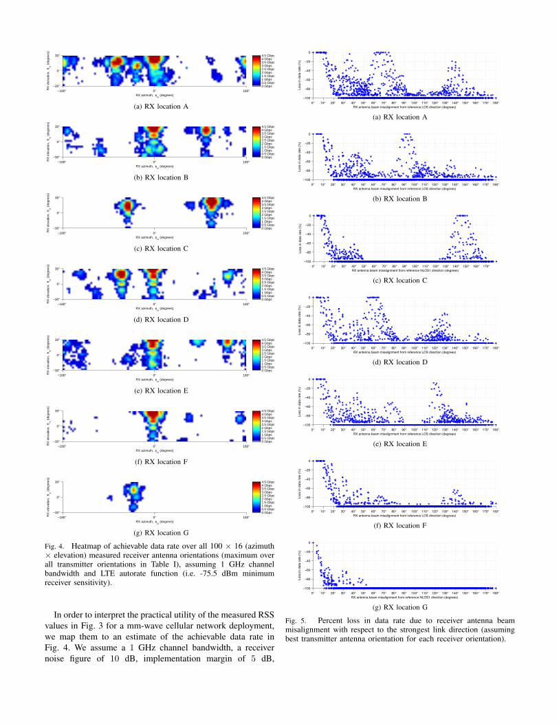
Fig. 4. Heatmap of achievable data rate over all 100 × 16 (azimuth× elevation) measured receiver antenna orientations (maximum overall transmitter orientations in Table I), assuming 1 GHz channelbandwidth and LTE autorate function (i.e. -75.5 dBm minimumreceiver sensitivity).
In order to interpret the practical utility of the measured RSSvalues in Fig. 3 for a mm-wave cellular network deployment,we map them to an estimate of the achievable data rate inFig. 4. We assume a 1 GHz channel bandwidth, a receivernoise figure of 10 dB, implementation margin of 5 dB,
0° 10° 20° 30° 40° 50° 60° 70° 80° 90° 100° 110° 120° 130° 140° 150° 160° 170° 180°
−100
−80
−60
−40
−20
0
RX antenna beam misalignment from reference LOS direction (degrees)
Loss
in d
ata
rate
(%
)
(a) RX location A
0° 10° 20° 30° 40° 50° 60° 70° 80° 90° 100° 110° 120° 130° 140° 150° 160° 170° 180°
−100
−80
−60
−40
−20
0
RX antenna beam misalignment from reference LOS direction (degrees)
Loss
in d
ata
rate
(%
)
(b) RX location B
0° 10° 20° 30° 40° 50° 60° 70° 80° 90° 100° 110° 120° 130° 140° 150° 160° 170°
−100
−80
−60
−40
−20
0
RX antenna beam misalignment from reference NLOS1 direction (degrees)
Loss
in d
ata
rate
(%
)
(c) RX location C
0° 10° 20° 30° 40° 50° 60° 70° 80° 90° 100° 110° 120° 130° 140° 150° 160° 170° 180°
−100
−80
−60
−40
−20
0
RX antenna beam misalignment from reference LOS direction (degrees)
Loss
in d
ata
rate
(%
)
(d) RX location D
0° 10° 20° 30° 40° 50° 60° 70° 80° 90° 100° 110° 120° 130° 140° 150° 160° 170° 180°
−100
−80
−60
−40
−20
0
RX antenna beam misalignment from reference LOS direction (degrees)
Loss
in d
ata
rate
(%
)
(e) RX location E
0° 10° 20° 30° 40° 50° 60° 70° 80° 90° 100° 110° 120° 130° 140° 150° 160° 170° 180°
−100
−80
−60
−40
−20
0
RX antenna beam misalignment from reference LOS direction (degrees)
Loss
in d
ata
rate
(%
)
(f) RX location F
0° 10° 20° 30° 40° 50° 60° 70° 80° 90° 100° 110° 120° 130° 140° 150° 160° 170° 180°
−100
−80
−60
−40
−20
0
RX antenna beam misalignment from reference NLOS1 direction (degrees)
Loss
in d
ata
rate
(%
)
(g) RX location G
Fig. 5. Percent loss in data rate due to receiver antenna beammisalignment with respect to the strongest link direction (assumingbest transmitter antenna orientation for each receiver orientation).

and the LTE Rel. 12 autorate function given in [16] as thetruncated Shannon bound with attenuation factor α = 0.75,minimum SNR of −6.5 dB, and maximum SNR of 17 dB.The corresponding top achievable data rate is 4.2568 Gbps,whereas the minimum receiver sensitivity is −75.5 dBm (fora data rate of 218.6 Mbps).
Fig. 4 reveals the far more restricted range of valid antennaorientations for obtaining high-speed cellular mm-wave links:only under a third of the antenna orientations with RSS abovethe noise floor in Fig. 3 result in a valid LTE-like link in Fig. 4.Moreover, on average only 9% of all considered antennaorientations per receiver location result in a link with data rateof over 1 Gbps, whereas the top data rate of 4.2568 Gbps isachievable for no more than 1% of the antenna orientations onaverage. These results reveal that very stringent beamsteeringrequirements must be met if mm-wave cellular networks areto deliver the promise of multi-Gbps connectivity.
To analyze in more detail the sensitivity of mm-waveoutdoor cellular links to suboptimal beamsteering, in Fig. 5we consider the degradation in data rate due to receive antennabeam misalignment with respect to the strongest link direction.Specifically, the scatter plots in Fig. 5 were obtained bycomputing, for each of the 1600 antenna orientations at a givenreceiver location, the angular distance from the centre of theLOS cluster (or strongest NLOS for locations C and G) andthe corresponding data rate drop in Fig. 4 from this referenceoptimal orientation. The clusters corresponding to the validLOS/NLOS links in Fig. 4 are thus evident as peaks in Fig. 5.
Let us first consider how sensitive the strongest LOS/NLOSlinks, corresponding to the leftmost cluster-peaks in Fig. 5 are.A misalignment of around 10◦ – in the order of the antennabeamwidth – results in almost no reduction in data rate forLOS links at locations A, B, and F. However, at the remainingreceiver locations, the strongest LOS/NLOS links typicallysuffer a data rate drop of 20% due to a 10◦ misalignment andan average drop of 50−100% due to a 20◦ misalignment. Theweaker NLOS links are even more sensitive to misalignment,e.g. as evident from the second cluster-peak in Fig. 5f at theangular distance of 139◦ from the reference LOS orientation.This poses a great challenge to providing stable high-speedconnectivity to mobile users in a mm-wave cellular network,given that changes in orientation in the order of 10◦ wouldoccur very frequently even for a quasi-stationary user, i.e. notwalking but holding the phone in their hand.
The receive antenna beam would need to be continuouslyre-steered to compensate for such “micro-movements”, andto provide the requisite channel state information, the userorientation relative to the environment should be continuouslymonitored. Furthermore, to support user mobility and over-come blockage of preferred transmission paths by moving ob-stacles, the transmit antenna would also need to be frequentlyre-steered (as illustrated in Figs. 1b–1h). Namely, the precisionbeamsteering requirements indicated by our measurementsfor seamless provisioning of multi-Gbps cellular data ser-vices impose a high network signalling and control overhead.It remains to be seen whether the resulting beamsteering
complexity proves prohibitive, making mm-wave deploymentspractically infeasible in outdoor mobile environments.
IV. CONCLUSIONS
We presented results of detailed angular measurements ofthe signal strength of directional 60 GHz outdoor mm-wavelinks, conducted at an example pico-cellular network site in amixed-use urban environment typical of European cities. Ourresults show that, although multi-Gbps mm-wave links areachievable for a substantial number of antenna orientations,mm-wave connectivity is highly site-specific and sensitive toorientation: a beam misalignment of only 10◦ can degrade theachievable data rate by 20−100%. Therefore, our results revealthat the beamsteering requirements for seamless multi-Gbpsmobile data provisioning are very stringent. This suggests thatit would be necessary to very frequently resteer the antennabeams to compensate for slight user movements and maintainQoS; the associated network control and signalling overheadmay make mm-wave deployments unattractive for outdoor mo-bile environments. Our ongoing work is studying the networkdesign opportunities and limitations of mm-wave networks,via further measurements and ray-tracing simulations.
ACKNOWLEDGEMENT
We thank S. Katsanevakis for help with construction of theRX rotation platform and P. Mahonen for useful discussions.
REFERENCES
[1] J. G. Andrews et al., “What will 5G be?” IEEE J. Select. AreasCommun., vol. 32, no. 6, pp. 1065–1082, June 2014.
[2] T. S. Rappaport et al., “Millimeter wave mobile communications for 5Gcellular: It will work!” IEEE Access, vol. 1, pp. 335–349, May 2013.
[3] A. F. Molisch and F. Tufvesson, “Propagation channel models for next-generation wireless communications systems,” IEICE Transactions onCommunications, vol. E97-B, no. 10, pp. 2022–2034, Oct. 2014.
[4] T. Rappaport, G. MacCartney, M. Samimi, and S. Sun, “Widebandmillimeter-wave propagation measurements and channel models forfuture wireless communication system design,” IEEE Trans. Commun.,vol. 63, no. 9, pp. 3029–3056, Sept. 2015.
[5] M. Samimi et al., “28 GHz angle of arrival and angle of departureanalysis for outdoor cellular communications using steerable beamantennas in New York City,” in Proc. IEEE VTC Spring, Dresden, 2013.
[6] G. MacCartney and T. Rappaport, “73 GHz millimeter wave propagationmeasurements for outdoor urban mobile and backhaul communicationsin New York City,” in Proc. IEEE ICC, Sydney, 2014.
[7] T. Rappaport, E. Ben-Dor, J. Murdock, and Y. Qiao, “38 GHz and 60GHz angle-dependent propagation for cellular & peer-to-peer wirelesscommunications,” in Proc. IEEE ICC, Ottawa, 2012.
[8] R. J. Weiler et al., “Outdoor millimeter-wave access for heterogeneousnetworks – path loss and system performance,” in Proc. IEEE PIMRC,Washington, 2014.
[9] Y. Zhu et al., “Demystifying 60 GHz outdoor picocells,” in Proc.MobiCom, Maui, 2014.
[10] T. Nitsche, A. Flores, E. Knightly, and J. Widmer, “Steering witheyes closed: Mm-Wave beam steering without in-band measurement,”in Proc. IEEE INFOCOM, Hong Kong, 2015.
[11] J. Arnold, L. Simic, M. Petrova, and P. Mahonen, “Demo: Spectrum-agile mm-wave packet radio implementation on USRPs,” in Proc. SRIFat MobiCom, Paris, 2015.
[12] Sivers IMA AB, FC1005V/00 V-Band Converter with LO, Data Sheet.[13] Flann Microwave, Model 25240-25 Standard Gain Horn, Data Sheet.[14] FCC, “In the Matter of Revision of Part 15 of the Commission’s Rules
Regarding Operation in the 57-64 GHz Band: Report and Order,” Tech.Rep. 13-112, 2013.

[15] “Amending Decision 2006/771/EC on Harmonisation of the RadioSpectrum for Use by Short-Range Devices and Repealing Decision2005/928/EC,” Tech. Rep. 2013/752/EU, 2013.
[16] 3GPP, “LTE; E-UTRA; RF system scenarios,” Tech. Rep. TR 36 942V12.0.0, Oct. 2014.