Embed Size (px)
Citation preview

D E S I G N G U I D E
6 0 0S E R I E S
2 0 0S E R I E S
7 0 0S E R I E S
4 0 0S E R I E S
®

SUB-ZERO® is a registered trademark of Sub-Zero Freezer Company, Inc.
D E S I G N G U I D E
PA G E S 4 - 2 4 PA G E S 6 1 - 6 9PA G E S 2 5 - 4 3 PA G E S 4 4 - 6 0
6 0 0S E R I E S
2 0 0S E R I E S
7 0 0S E R I E S
4 0 0S E R I E S
®

Welcome to Sub-Zero. We make the ultimate built-in, integrated and under-counter refrigerators and freezers, and wine storage units. We offer more solu-tions to your daily design problems of trying to work the largest appliance into ahome without being obtrusive. Placing refrigeration in the home is no longer aproblem, but an opportunity to exercise your creativity.
Sub-Zero has rethought traditional built-in refrigeration, a category it pioneeredwith nearly 60 years of experience. When our complete line of configurations –over-and-under, side-by-side, all refrigerator and all freezer – are coupled withthree design alternatives and classic, platinum and carbon stainless steel finish-es, the results are unlimited flexibility in satisfying your client’s needs for resi-dential refrigeration. Our new glass door units, Models 601RG, 611G and 650G,are sure to allow you more options. New Models 661, 685 and 695 will replaceModels 561, 680 and 690 in summer of 2004. The new ice and water dispensingModels 685 and 695 will now be available in the overlay application.
With the 700 Series, we've taken the idea a step further – integrated refrigera-tion. Refrigerators and freezers you can hide anywhere in the house, inside furni-ture or cabinetry of your choosing. Created to blend invisibly into your home'sdecor, the 700 Series lets you integrate refrigeration into the kitchen, mastersuite, media room or workout room. Available as tall units or two drawer baseunits, the 700 Series expands the possibilities for the way you shape your home.
With the 400 Series, Sub-Zero is breaking with conventional ways of offeringwine storage for designers and their clients. Our four built-in units offer unlimit-ed design and storage capabilities, along with the free-standing Model 424FS.
In all instances, you can depend on Sub-Zero. Our reputation is legendary. Wehave engineered and manufactured the best product in the business, and westand behind our product. Each one of our units is tested before it leaves ourfactories and if service is necessary, there is a network of thousands of factory-trained technicians to help you.
Each unit is protected by the Sub-Zero Freezer Company Products Limited War-ranty that covers the entire unit for two years for parts and labor from the dateof installation, exclusions apply. See the details of our warranty on page 70.
IMPORTANT NOTE: As you follow these instructions, you will notice warning andcaution symbols. This blocked information is important for the safe and efficientinstallation of this Sub-Zero. There are two types of potential hazards that mayoccur during this installation.
Another footnote we would like to identify is; IMPORTANT NOTE: This highlightsinformation that is especially relevant to a problem-free installation.
S U B - Z E R O – D E S I G N S O L U T I O N S
3
WARNING
states a hazard that may cause serious injury or death if precautions are notfollowed.
CAUTION
signals a situation where minor injury or product damage may occur if youdo not follow instructions.

Model 695/SStainless Steel
Model 695/OOverlay
Model 695/FFramed
4
C R E A T I N G S O L U T I O N S F O R H O M E R E F R I G E R A T I O N
Sub-Zero’s 600 Series offers you the most complete set of design options in built-in refrigeration for all of its models. From the classic look of the framed unit tothe beauty of the overlay models to the professional treatment of the wrappedstainless steel doors.
In the illustrations below, we have shown the three different design configura-tions of the framed, overlay and stainless steel units applied to the Model 695.Please note how we qualify the different looks with the model number.
Aside from the classic stainless steel, Sub-Zero offers two additional premiumstainless steel finishes, platinum and carbon, on all of its models (except Models680, 685, 690 and 695) and many of its related accessories. Product and acces-sories in the premium finishes will be regarded as special orders and must beordered 90 days before you expect delivery.
Glass doors are featured on Models 601RG, 611G and 650G. They're beautiful.They each come in a framed, overlay and stainless steel design and meet strin-gent energy numbers. Sub-Zero has it all.
• The traditional framed units will come with an elegant full-length handle andan 11" (279) louvered grille.
• Overlay models will come with no handle hardware, because the beauty of thisdesign is that you can match the surrounding cabinetry hardware; however, wedo offer optional handles as sales accessories. Models 680 and 690 are not avail-able in the overlay design application. The new ice and water dispensing Models685 and 695 being introduced in summer of 2004 will be able to accept overlaypanels. Overlay models will come with a standard 11" (279) panel grille whichwill accept decorative panel inserts. Models 601R, 601RG and 601F are onlyavailable with the louvered grille. No panel grille option is available.
• All stainless steel models are offered in the classic stainless steel finish and inthe premium finishes of platinum and carbon. Stainless steel models come witha standard 11" (279) heavy-duty grille, 1" (25) diameter stainless steel handlesand a stainless steel kickplate.
All grilles will be offered as options in 1" (25) increments from 10" (254) to 15"(381) and can be ordered as sales accessories.
6 0 0S E R I E S
B U I L T - I N R E F R I G E R A T I O N
42"(1067)
36"(914)
42"(1067)
42"(1067)
48"(1219)
48"(1219)
48"(1219)
36"(914)
84"(2134)
5
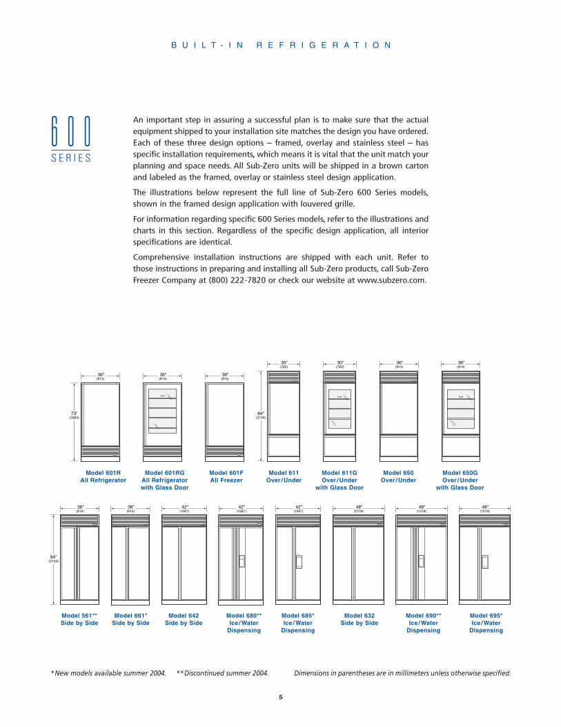
An important step in assuring a successful plan is to make sure that the actualequipment shipped to your installation site matches the design you have ordered.Each of these three design options – framed, overlay and stainless steel – hasspecific installation requirements, which means it is vital that the unit match yourplanning and space needs. All Sub-Zero units will be shipped in a brown cartonand labeled as the framed, overlay or stainless steel design application.
The illustrations below represent the full line of Sub-Zero 600 Series models,shown in the framed design application with louvered grille.
For information regarding specific 600 Series models, refer to the illustrations andcharts in this section. Regardless of the specific design application, all interiorspecifications are identical.
Comprehensive installation instructions are shipped with each unit. Refer tothose instructions in preparing and installing all Sub-Zero products, call Sub-ZeroFreezer Company at (800) 222-7820 or check our website at www.subzero.com.
Model 650Over /Under
Model 611GOver /Under
with Glass Door
Model 601FAll Freezer
Model 601RAll Refrigerator
Model 661*Side by Side
Model 642Side by Side
Model 632Side by Side
Model 690**Ice /Water
Dispensing
Model 680**Ice /Water
Dispensing
Model 601RGAll Refrigeratorwith Glass Door
B U I L T - I N R E F R I G E R A T I O N
6 0 0S E R I E S
Model 650GOver /Under
with Glass Door
Model 611Over /Under
Model 695*Ice /Water
Dispensing
Model 685*Ice /Water
Dispensing
*New models available summer 2004. **Discontinued summer 2004.
Model 561**Side by Side
Dimensions in parentheses are in millimeters unless otherwise specified.
36"(914)
36"(914)
36"(914)
73"(1854)
30"(762)
36"(914)
30"(762)
36"(914)
84"(2134)

B U I L T - I N R E F R I G E R A T I O N
6
601R 601F 611
Model 601REnergy Star Qualified
MODEL OPTIONS
601R/F Framed Design
601R/O Overlay Design
601R/S Classic Stainless
601R/P Platinum Stainless
601R/B Carbon Stainless
SPECIFICATIONS
All Refrigerator
36"W x 73"H x 24"D(914 x 1854 x 610)
Refrigerator Capacity19.9 cu ft (564 L)
Minimum Height Required723/4" (1848)
Door Swing Clearance361/16" (916)
Specify LH or RH Door Swing
Annual Energy Usage400 kWh / $33*
Shipping Weight391 lbs (177 kg) F/O420 lbs (191 kg) S/P/B
FEATURES
Refrigerator
4 Adjustable Glass Shelves
1 Stationary Glass Shelf
High Humidity Crisper Drawer
Adjustable Roll-Out Deli Basket
3 Adjustable Door Shelves
Adjustable Dairy Compartment
Egg Container
Model 601RGEnergy Star Qualified
MODEL OPTIONS
601RG/F Framed Design
601RG/O Overlay Design
601RG/S Classic Stainless
601RG/P Platinum Stainless
601RG/B Carbon Stainless
SPECIFICATIONS
All Refrigeratorwith Glass Door
36"W x 73"H x 24"D(914 x 1854 x 610)
Refrigerator Capacity20.1 cu ft (569 L)
Minimum Height Required723/4" (1848)
Door Swing Clearance361/16" (916)
Specify LH or RH Door Swing
Annual Energy Usage402 kWh / $33*
Shipping Weight400 lbs (181 kg) F/O430 lbs (195 kg) S/P/B
FEATURES
Refrigerator
4 Adjustable Glass Shelves
1 Stationary Glass Shelf
High Humidity Crisper Drawer
Triple Pane UV Resistant LowEnergy Glass Door
Optional Roll-Out Deli BasketAvailable
Egg Container
Model 601F
MODEL OPTIONS
601F/F Framed Design
601F/O Overlay Design
601F/S Classic Stainless
601F/P Platinum Stainless
601F/B Carbon Stainless
SPECIFICATIONS
All Freezer
36"W x 73"H x 24"D(914 x 1854 x 610)
Freezer Capacity19.3 cu ft (547 L)
Minimum Height Required723/4" (1848)
Door Swing Clearance361/16" (916)
Specify LH or RH Door Swing
Annual Energy Usage742 kWh / $62*
Shipping Weight378 lbs (171 kg) F/O406 lbs (184 kg) S/P/B
FEATURES
Freezer
Automatic Ice Maker
3 Adjustable Wire Shelves
1 Stationary Glass Shelf
3 Storage Drawers
5 Adjustable Door Shelves
Model 611Energy Star Qualified
MODEL OPTIONS
611/F Framed Design
611/O Overlay Design
611/S Classic Stainless
611/P Platinum Stainless
611/B Carbon Stainless
SPECIFICATIONS
Over/Under
30"W x 84"H x 24"D(762 x 2134 x 610)
Refrigerator Capacity12.7 cu ft (360 L)
Freezer Capacity3.9 cu ft (110 L)
Minimum Height Required827/8" (2105)
Door Swing Clearance301/8" (765)
Specify LH or RH Door Swing
Annual Energy Usage465 kWh / $39*
Shipping Weight430 lbs (195 kg) F/O462 lbs (210 kg) S/P/B
FEATURES
Refrigerator
3 Adjustable Glass Shelves
1 Stationary Glass Shelf
High Humidity Crisper Drawer
Adjustable Roll-Out Deli Basket
2 Adjustable Door Shelves
Adjustable Dairy Compartment
Egg Container
Freezer
Automatic Ice Maker
Two-Tier Pull-Out Drawer
Model 601R Model 601RG Model 601F Model 611
*Annual energy costs are basedon 8.29 cents per kilowatt hour.
Dimensions in parentheses arein millimeters unless otherwisespecified.
All units are shown in theframed design application withlouvered grille.
B U I L T - I N R E F R I G E R A T I O N
7
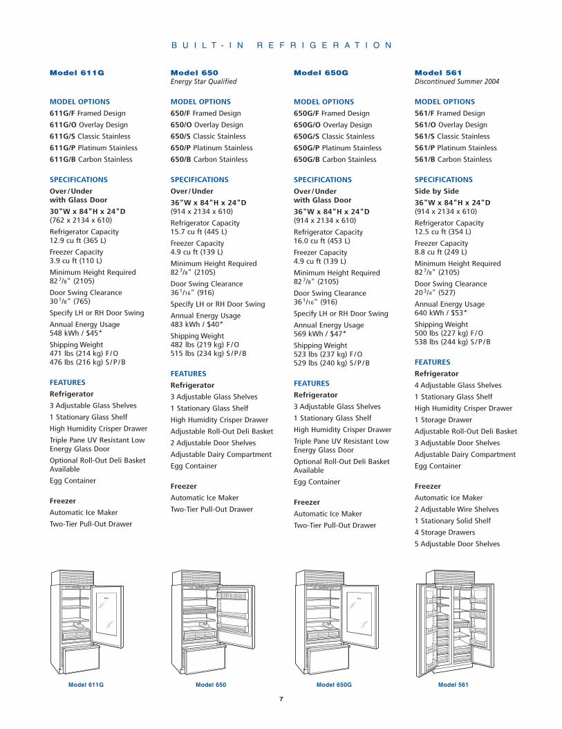
Model 650Energy Star Qualified
MODEL OPTIONS
650/F Framed Design
650/O Overlay Design
650/S Classic Stainless
650/P Platinum Stainless
650/B Carbon Stainless
SPECIFICATIONS
Over/Under
36"W x 84"H x 24"D(914 x 2134 x 610)
Refrigerator Capacity15.7 cu ft (445 L)
Freezer Capacity4.9 cu ft (139 L)
Minimum Height Required827/8" (2105)
Door Swing Clearance361/16" (916)
Specify LH or RH Door Swing
Annual Energy Usage483 kWh / $40*
Shipping Weight482 lbs (219 kg) F/O515 lbs (234 kg) S/P/B
FEATURES
Refrigerator
3 Adjustable Glass Shelves
1 Stationary Glass Shelf
High Humidity Crisper Drawer
Adjustable Roll-Out Deli Basket
2 Adjustable Door Shelves
Adjustable Dairy Compartment
Egg Container
Freezer
Automatic Ice Maker
Two-Tier Pull-Out Drawer
650
Model 650
611G
Model 611G
Model 650G
MODEL OPTIONS
650G/F Framed Design
650G/O Overlay Design
650G/S Classic Stainless
650G/P Platinum Stainless
650G/B Carbon Stainless
SPECIFICATIONS
Over/Underwith Glass Door
36"W x 84"H x 24"D(914 x 2134 x 610)
Refrigerator Capacity16.0 cu ft (453 L)
Freezer Capacity4.9 cu ft (139 L)
Minimum Height Required827/8" (2105)
Door Swing Clearance361/16" (916)
Specify LH or RH Door Swing
Annual Energy Usage569 kWh / $47*
Shipping Weight523 lbs (237 kg) F/O529 lbs (240 kg) S/P/B
FEATURES
Refrigerator
3 Adjustable Glass Shelves
1 Stationary Glass Shelf
High Humidity Crisper Drawer
Triple Pane UV Resistant LowEnergy Glass Door
Optional Roll-Out Deli BasketAvailable
Egg Container
Freezer
Automatic Ice Maker
Two-Tier Pull-Out Drawer
650G
Model 650G
Model 611G
MODEL OPTIONS
611G/F Framed Design
611G/O Overlay Design
611G/S Classic Stainless
611G/P Platinum Stainless
611G/B Carbon Stainless
SPECIFICATIONS
Over/Underwith Glass Door
30"W x 84"H x 24"D(762 x 2134 x 610)
Refrigerator Capacity12.9 cu ft (365 L)
Freezer Capacity3.9 cu ft (110 L)
Minimum Height Required827/8" (2105)
Door Swing Clearance301/8" (765)
Specify LH or RH Door Swing
Annual Energy Usage548 kWh / $45*
Shipping Weight471 lbs (214 kg) F/O476 lbs (216 kg) S/P/B
FEATURES
Refrigerator
3 Adjustable Glass Shelves
1 Stationary Glass Shelf
High Humidity Crisper Drawer
Triple Pane UV Resistant LowEnergy Glass Door
Optional Roll-Out Deli BasketAvailable
Egg Container
Freezer
Automatic Ice Maker
Two-Tier Pull-Out Drawer
Model 561Discontinued Summer 2004
MODEL OPTIONS
561/F Framed Design
561/O Overlay Design
561/S Classic Stainless
561/P Platinum Stainless
561/B Carbon Stainless
SPECIFICATIONS
Side by Side
36"W x 84"H x 24"D(914 x 2134 x 610)
Refrigerator Capacity12.5 cu ft (354 L)
Freezer Capacity8.8 cu ft (249 L)
Minimum Height Required827/8" (2105)
Door Swing Clearance203/4" (527)
Annual Energy Usage640 kWh / $53*
Shipping Weight500 lbs (227 kg) F/O538 lbs (244 kg) S/P/B
FEATURES
Refrigerator
4 Adjustable Glass Shelves
1 Stationary Glass Shelf
High Humidity Crisper Drawer
1 Storage Drawer
Adjustable Roll-Out Deli Basket
3 Adjustable Door Shelves
Adjustable Dairy Compartment
Egg Container
Freezer
Automatic Ice Maker
2 Adjustable Wire Shelves
1 Stationary Solid Shelf
4 Storage Drawers
5 Adjustable Door Shelves
561 561
Model 561

B U I L T - I N R E F R I G E R A T I O N
8
Model 680Discontinued Summer 2004
MODEL OPTIONS
680/F Framed Design
680/S Classic Stainless
SPECIFICATIONS
Side by SideIce/Water Dispensing
42"W x 84"H x 24"D(1067 x 2134 x 610)
Refrigerator Capacity15.6 cu ft (442 L)
Freezer Capacity8.2 cu ft (232 L)
Minimum Height Required827/8" (2105)
Door Swing Clearance259/16" (649)
Annual Energy Usage698 kWh / $58*
Shipping Weight569 lbs (258 kg) F608 lbs (276 kg) S
FEATURES
Refrigerator
4 Adjustable Glass Shelves
1 Stationary Glass Shelf
High Humidity Crisper Drawer
1 Storage Drawer
Adjustable Roll-Out Deli Basket
3 Adjustable Door Shelves
Adjustable Dairy Compartment
Egg Container
Freezer
Automatic Ice Maker
2 Adjustable Wire Shelves
1 Stationary Solid Shelf
3 Storage Drawers
5 Adjustable Door Shelves
2 Juice Can Shelves
680 680
Model 680
Model 642
MODEL OPTIONS
642/F Framed Design
642/O Overlay Design
642/S Classic Stainless
642/P Platinum Stainless
642/B Carbon Stainless
SPECIFICATIONS
Side by Side
42"W x 84"H x 24"D(1067 x 2134 x 610)
Refrigerator Capacity16.2 cu ft (459 L)
Freezer Capacity8.2 cu ft (232 L)
Minimum Height Required827/8" (2105)
Door Swing Clearance259/16" (649)
Annual Energy Usage653 kWh / $54*
Shipping Weight541 lbs (245 kg) F/O582 lbs (264 kg) S/P/B
FEATURES
Refrigerator
4 Adjustable Glass Shelves
1 Stationary Glass Shelf
High Humidity Crisper Drawer
1 Storage Drawer
Adjustable Roll-Out Deli Basket
3 Adjustable Door Shelves
Adjustable Dairy Compartment
Egg Container
Freezer
Automatic Ice Maker
3 Adjustable Wire Shelves
1 Stationary Solid Shelf
3 Storage Drawers
5 Adjustable Door Shelves
642 642
Model 642
Model 685Available Summer 2004
MODEL OPTIONS
685/F Framed or Partial Framed
685/O Overlay Design
685/S Classic Stainless
SPECIFICATIONS
Side by SideIce/Water Dispensing
42"W x 84"H x 24"D(1067 x 2134 x 610)
Refrigerator Capacity15.6 cu ft (442 L)
Freezer Capacity8.2 cu ft (232 L)
Minimum Height Required827/8" (2105)
Door Swing Clearance259/16" (649)
Annual Energy Usage698 kWh / $58*
Shipping Weight569 lbs (258 kg) F/O608 lbs (276 kg) S
FEATURES
Refrigerator
4 Adjustable Glass Shelves
1 Stationary Glass Shelf
High Humidity Crisper Drawer
1 Storage Drawer
Adjustable Roll-Out Deli Basket
3 Adjustable Door Shelves
Adjustable Dairy Compartment
Egg Container
Freezer
Automatic Ice Maker
2 Adjustable Wire Shelves
1 Stationary Wire Shelf
3 Storage Drawers
5 Adjustable Door Shelves
2 Juice Can Shelves
685 685
Model 685
Model 661Available Summer 2004
MODEL OPTIONS
661/F Framed Design
661/O Overlay Design
661/S Classic Stainless
661/P Platinum Stainless
661/B Carbon Stainless
SPECIFICATIONS
Side by Side
36"W x 84"H x 24"D(914 x 2134 x 610)
Refrigerator Capacity12.5 cu ft (354 L)
Freezer Capacity8.8 cu ft (249 L)
Minimum Height Required827/8" (2105)
Door Swing Clearance203/4" (527)
Annual Energy Usage640 kWh / $53*
Shipping Weight500 lbs (227 kg) F/O538 lbs (244 kg) S/P/B
FEATURES
Refrigerator
4 Adjustable Glass Shelves
1 Stationary Glass Shelf
High Humidity Crisper Drawer
1 Storage Drawer
Adjustable Roll-Out Deli Basket
3 Adjustable Door Shelves
Adjustable Dairy Compartment
Egg Container
Freezer
Automatic Ice Maker
2 Adjustable Wire Shelves
1 Stationary Solid Shelf
4 Storage Drawers
5 Adjustable Door Shelves
661 661
Model 661
B U I L T - I N R E F R I G E R A T I O N
9
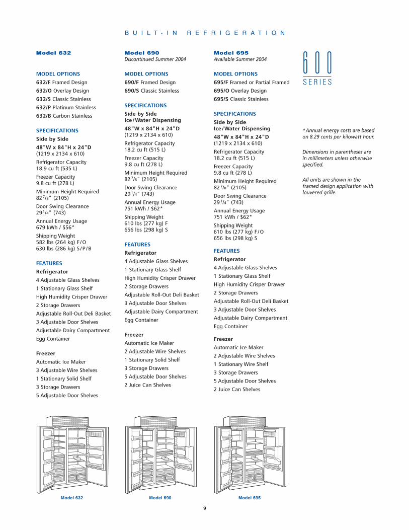
Model 632
MODEL OPTIONS
632/F Framed Design
632/O Overlay Design
632/S Classic Stainless
632/P Platinum Stainless
632/B Carbon Stainless
SPECIFICATIONS
Side by Side
48"W x 84"H x 24"D(1219 x 2134 x 610)
Refrigerator Capacity18.9 cu ft (535 L)
Freezer Capacity9.8 cu ft (278 L)
Minimum Height Required827/8" (2105)
Door Swing Clearance291/4" (743)
Annual Energy Usage679 kWh / $56*
Shipping Weight582 lbs (264 kg) F/O630 lbs (286 kg) S/P/B
FEATURES
Refrigerator
4 Adjustable Glass Shelves
1 Stationary Glass Shelf
High Humidity Crisper Drawer
2 Storage Drawers
Adjustable Roll-Out Deli Basket
3 Adjustable Door Shelves
Adjustable Dairy Compartment
Egg Container
Freezer
Automatic Ice Maker
3 Adjustable Wire Shelves
1 Stationary Solid Shelf
3 Storage Drawers
5 Adjustable Door Shelves
632 632
690 690
Model 690Model 632
Model 690Discontinued Summer 2004
MODEL OPTIONS
690/F Framed Design
690/S Classic Stainless
SPECIFICATIONS
Side by SideIce/Water Dispensing
48"W x 84"H x 24"D(1219 x 2134 x 610)
Refrigerator Capacity18.2 cu ft (515 L)
Freezer Capacity9.8 cu ft (278 L)
Minimum Height Required827/8" (2105)
Door Swing Clearance291/4" (743)
Annual Energy Usage751 kWh / $62*
Shipping Weight610 lbs (277 kg) F656 lbs (298 kg) S
FEATURES
Refrigerator
4 Adjustable Glass Shelves
1 Stationary Glass Shelf
High Humidity Crisper Drawer
2 Storage Drawers
Adjustable Roll-Out Deli Basket
3 Adjustable Door Shelves
Adjustable Dairy Compartment
Egg Container
Freezer
Automatic Ice Maker
2 Adjustable Wire Shelves
1 Stationary Solid Shelf
3 Storage Drawers
5 Adjustable Door Shelves
2 Juice Can Shelves
695 695
Model 695
Model 695Available Summer 2004
MODEL OPTIONS
695/F Framed or Partial Framed
695/O Overlay Design
695/S Classic Stainless
SPECIFICATIONS
Side by SideIce/Water Dispensing
48"W x 84"H x 24"D(1219 x 2134 x 610)
Refrigerator Capacity18.2 cu ft (515 L)
Freezer Capacity9.8 cu ft (278 L)
Minimum Height Required827/8" (2105)
Door Swing Clearance291/4" (743)
Annual Energy Usage751 kWh / $62*
Shipping Weight610 lbs (277 kg) F/O656 lbs (298 kg) S
FEATURES
Refrigerator
4 Adjustable Glass Shelves
1 Stationary Glass Shelf
High Humidity Crisper Drawer
2 Storage Drawers
Adjustable Roll-Out Deli Basket
3 Adjustable Door Shelves
Adjustable Dairy Compartment
Egg Container
Freezer
Automatic Ice Maker
2 Adjustable Wire Shelves
1 Stationary Wire Shelf
3 Storage Drawers
5 Adjustable Door Shelves
2 Juice Can Shelves
*Annual energy costs are basedon 8.29 cents per kilowatt hour.
Dimensions in parentheses arein millimeters unless otherwisespecified.
All units are shown in theframed design application withlouvered grille.
6 0 0S E R I E S

10
F E A T U R E S A N D O P T I O N S
Sub-Zero's design, beauty and quality are reflected in thebroad range of standard features that put Sub-Zero in aclass by itself.
New Models 661, 685 and 695 will replace Models 561, 680and 690 in summer of 2004.
• Framed models for the classic look that made Sub-Zerofamous, feature a louvered grille and elegant full-lengthhandle.An optional panel grille is available for framed units,except for Models 601R, 601RG and 601F. Optional panelconversion kits are available for the new ice and water dis-pensing Models 685 and 695, framed application, see page13 for details.
• Overlay models blend seamlessly into your overall roomdesign and complement surrounding cabinetry. You get toadd decorative hardware. Overlay models will come with apanel grille which will accept decorative panel inserts. Mod-els 680 and 690 are not available in the overlay designapplication, however, the new ice and water dispensingModels 685 and 695 will offer the overlay application.
• Stainless steel models feature wrapped doors, 1" (25)diameter stainless steel handles and heavy-duty grilledesigned specifically to enhance the aesthetics of the pro-fessional look of kitchens today. All 600 Series stainlesssteel models are offered in the classic stainless steel finishand in the premium finishes of platinum and carbon, exceptfor Models 680, 685, 690 and 695 which are offered in theclassic stainless steel finish only. The premium finishes aretreated as special orders and must be ordered 90 daysbefore you expect delivery.
Dual Refrigeration System. All 600 Series combinationunits have the exclusive Sub-Zero dual refrigeration system,which ensures the freshest food and energy efficiency at thesame time. You have precise independent control of therefrigerator and freezer compartments.
Glass Door. Model 601RG is an all refrigerator unit featur-ing a glass door. Models 611G and 650G are over /undercombination units where the refrigerator has a glass door.These glass door units come in framed, overlay and stain-less steel designs, meet stringent energy requirements andare available in right-hand or left-hand door swing.
Ice and Water Dispensing. Models 680, 685, 690 and 695feature a dispenser that gives you both ice and chilledwater through the refrigerator door.
Fresh Food. High humidity crisper drawer is large and deepwith smooth sides for easy cleaning. The drawer featuresremovable dividers.
Electronic Controls. Controls are up front and easy to use.They give your customer digital readings for quick, easy-to-read reference. Up-front controls also keep your clientinformed about the operation of the unit on a continuousbasis. The microprocessor gives you better control, auto-matic defrosting that senses, then adapts to your use pat-terns, and a vacuum condenser indicator light (exceptModel 561).
Improved Lighting. Bright lighting spreads even illumina-tion throughout the compartment and conceals the source.
Door Shelves. All door shelves are adjustable for completeflexibility and convenience.
Spill-Proof Shelves. Cantilevered shelves make reposition-ing quick and easy. They are easy to clean and spill-proof.They're steel reinforced to provide durability and reliability.
Dairy Storage. Dairy compartment is adjustable, with easy,one door access, compartment dividers and a clean design.The dairy shelf is magnetically sealed to maintain freshness.
Automatic Ice. Ice maker provides high quality, crescentshaped ice that won't stick to the side of the glass.
Built-in Look. Shallow depth design means access is easyto any area of the refrigerator.
Tight Seal. Magnetic gaskets around all doors give extratight seals.
Energy Efficient. Our solid core doors improve insulationand structural integrity, and help us exceed tough DOEEnergy Standards.
Kickplate. Solid, adjustable kickplate gives a true built-inlook, and conforms to American Institute of Architects stan-dards.
Sub-Zero Warranty. Like all Sub-Zero units, the 600 Seriesis covered by the Sub-Zero Freezer Company Products Lim-ited Warranty, exclusions apply. See page 70 for details.
B U I L T - I N R E F R I G E R A T I O N

11
B U I L T - I N R E F R I G E R A T I O N
P L A N N I N G I N F O R M A T I O N
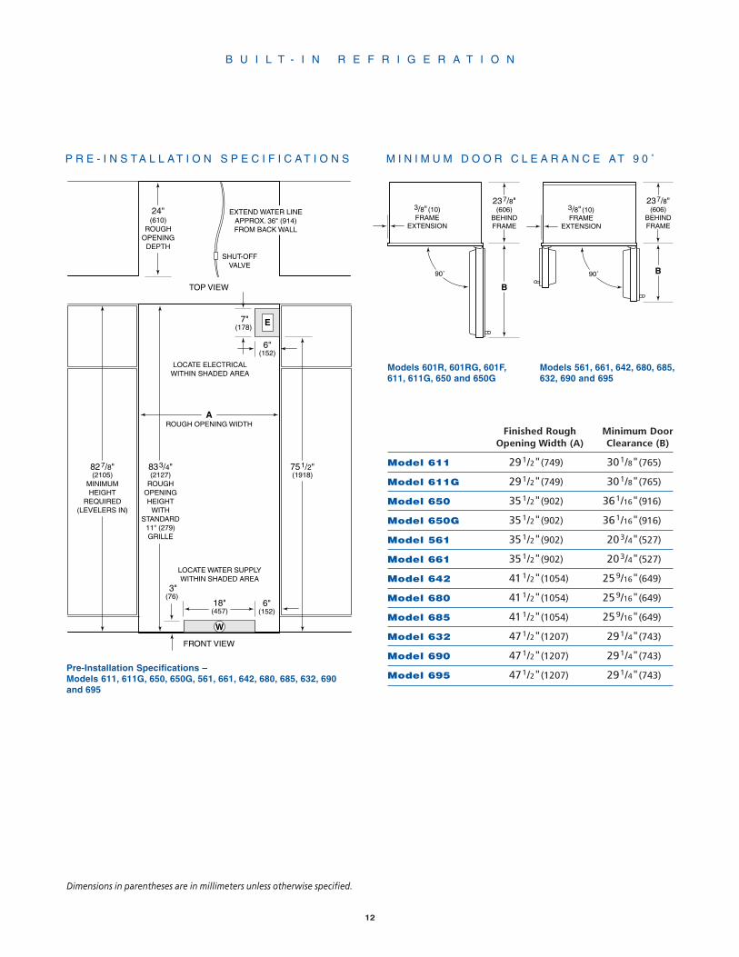
Although the 600 Series offers a wide range of designs andconfigurations, the basic planning considerations for allmodels have much in common. As you integrate Sub-Zerounits into your overall plan, review installation require-ments for your particular units. The Pre-Installation Specifi-cations illustrations and charts provide planning informa-tion for all Sub-Zero 600 Series units – framed, overlay andstainless steel.
Allow door(s) to open a minimum of 90˚ or you'll have prob-lems removing drawers. With the door opening at 90˚, youmay have to move drawers slightly to clear the door interi-or. Refer to the minimum door clearances in the Pre-Instal-lation Specifications chart.
• For corner installations, allow for a minimum 3" (76) fillerso that the door can open to 90˚. If you're using raised pan-els, consider using a wider filler.
• When units are installed side by side, a filler strip is rec-ommended. The width of this filler strip will vary dependingon the configuration and panels you use.
• Be sure to add the filler strip width to your finished roughopening dimension. In any side by side installation withouta filler strip, add an additional 1/2" (13) to your combinednumbers. This will allow for the proper width.
IMPORTANT NOTE: Refer to the full-scale illustrations atthe end of this section for specifics on door openings andfiller size alternatives.
723/4"(1848)
ROUGHOPENINGHEIGHT
723/4"(1848)
MINIMUMHEIGHT
REQUIRED(LEVELERS IN)
24"(610)
ROUGHOPENING
DEPTH
11"(279)
3"(76)
24"(610)
W
LOCATE WATER SUPPLYWITHIN BOTTOM SHADEDAREA ONLY (601F ONLY)
LOCATE ELECTRICALWITHIN ENTIRE SHADED AREA
6"(152)
E
SHUT-OFFVALVE
EXTEND WATER LINEAPPROX. 36" (914)FROM BACK WALL
(601F ONLY)
AROUGH OPENING WIDTH
FRONT VIEW
TOP VIEW
Finished Rough Minimum DoorOpening Width (A) Clearance (B)
Model 601R 351/2"(902) 361/16"(916)
Model 601RG 351/2"(902) 361/16"(916)
Model 601F 351/2"(902) 361/16"(916)
P R E - I N S T A L L A T I O N S P E C I F I C A T I O N S
Dimensions in parentheses are in millimeters unless otherwise specified.
Pre-Installation Specifications – Models 601R, 601RG and 601F
12
B U I L T - I N R E F R I G E R A T I O N
833/4"(2127)
ROUGHOPENINGHEIGHT
WITHSTANDARD
11" (279)GRILLE
827/8"(2105)
MINIMUMHEIGHT
REQUIRED(LEVELERS IN)
751/2"(1918)
7"(178)
6"(152)
AROUGH OPENING WIDTH
24"(610)
ROUGHOPENING
DEPTH
E
3"(76)
18"(457)
W
LOCATE WATER SUPPLYWITHIN SHADED AREA
LOCATE ELECTRICALWITHIN SHADED AREA
6"(152)
SHUT-OFFVALVE
EXTEND WATER LINEAPPROX. 36" (914)FROM BACK WALL
FRONT VIEW
TOP VIEW
Finished Rough Minimum DoorOpening Width (A) Clearance (B)
Model 611 291/2"(749) 301/8"(765)
Model 611G 291/2"(749) 301/8"(765)
Model 650 351/2"(902) 361/16"(916)
Model 650G 351/2"(902) 361/16"(916)
Model 561 351/2"(902) 203/4"(527)
Model 661 351/2"(902) 203/4"(527)
Model 642 411/2"(1054) 259/16"(649)
Model 680 411/2"(1054) 259/16"(649)
Model 685 411/2"(1054) 259/16"(649)
Model 632 471/2"(1207) 291/4"(743)
Model 690 471/2"(1207) 291/4"(743)
Model 695 471/2"(1207) 291/4"(743)
B
237/8"(606)
BEHINDFRAME
3/8" (10)FRAME
EXTENSION
90˚ B
237/8"(606)
BEHINDFRAME
3/8" (10)FRAME
EXTENSION
90˚
Models 601R, 601RG, 601F,611, 611G, 650 and 650G
Models 561, 661, 642, 680, 685,632, 690 and 695
M I N I M U M D O O R C L E A R A N C E A T 9 0 ˚
Dimensions in parentheses are in millimeters unless otherwise specified.
Pre-Installation Specifications –Models 611, 611G, 650, 650G, 561, 661, 642, 680, 685, 632, 690and 695
P R E - I N S T A L L A T I O N S P E C I F I C A T I O N S

13
B U I L T - I N R E F R I G E R A T I O N
I N T E G R A T I N G C A B I N E T R Y
In your plan for panels, be sure you are working with theSub-Zero panel design family called for in your design. Ifyou have chosen the stainless steel design, the unit will beshipped complete with wrapped stainless steel doors andhandle hardware. You will not have to install panels.
F R A M E D D O O R P A N E L S
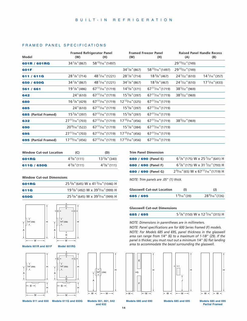
If you and your client have ordered a framed design model,you will be adding panels to give the unit the customSub-Zero look. For exact door panel dimensions for 600Series framed units, refer to the Framed Panel Specificationschart and illustrations on the following page. Also refer tothe full-scale illustrations at the end of this section for paneland handle considerations.
The traditional framed units come with an elegant smoothfull-length handle. Optional extended full-length handleswhich provide additional finger clearance for raised panels,are available through your Sub-Zero dealer.
If the thickness of the custom panels is less than 1/4" (6),they must be backed up with a sheet of shim material tobuild the total thickness to 1/4" (6). If the panel is thickerthan 1/4" (6), an edge must be routed around the panel toensure a proper fit. Refer to illustrations 1 and 2.
PANELS 1/4" (6) THICK OR LESS
1/4" (6) Panel
Trim reveal 1/4" (6) min
PANELS THICKER THAN 1/4" (6)
Trim reveal 1/4" (6) min
Rout to 1/4" (6)thickness
Illus. 1 Illus. 2
IMPORTANT NOTE: On all models except Models 680 and690, routing, recessing or optional extended handles maybe required on raised panels for finger clearance under thehandle. Refer to the full-scale illustrations at the end of thissection.
IMPORTANT NOTE: The weight of each panel cannotexceed 50 lbs (23 kg).
For glass door Models 601RG, 611G and 650G, the refriger-ator door panel must include a cut-out to accommodate thewindow. Refer to the Framed Panel Specifications chart andillustrations on the following page.
IMPORTANT NOTE: On glass door models, the glass por-tion of the door must be exposed and not covered by anypart of the panel.
For Models 685 and 695, the refrigerator door panel mustinclude a cut-out to accommodate the glasswell and bezel.The thickness of the panel in this area can range from 1/4"(6) to a maximum of 1-1/8" (29). If the panel is thicker, pro-visions must be made to rout out a space to accommodatethe decorative bezel surrounding the glasswell.
For Models 685 and 695, adequate clearance under therefrigerator door handle is required to assure proper accessto the glasswell. Refer to the full-scale illustration at theend of this section for the proper mounting placement ofthe refrigerator door handle.
To install framed panels, see the detailed procedures out-lined in the Sub-Zero 600 Series Installation Guide.
14
B U I L T - I N R E F R I G E R A T I O N
WW WW
H14" (356)
WW
H
A
WW
HG
F
E
H
C
C C
H
W
H
A
B
D
14"(356)
H
W
H
A
B
14"(356)
C
W
H
A
C C
D
14"(356)
W
H
A
14"(356)
J
I
Models 601R and 601F
Models 611 and 650 Models 561, 661, 642and 632
Models 685 and 695
Model 601RG
Models 611G and 650G
Framed Refrigerator Panel Framed Freezer Panel Raised Panel Handle RecessModel (W) (H) (W) (H) (A) (B)
601R / 601RG 341/8"(867) 5815/16"(1497) 2915/32"(749)
601F 341/8"(867) 5815/16"(1497) 2915/32"(749)
611 / 611G 281/8"(714) 481/16"(1221) 281/8"(714) 183/8"(467) 241/32"(610) 141/16"(357)
650 / 650G 341/8"(867) 481/16"(1221) 341/8"(867) 183/8"(467) 241/32"(610) 171/16"(433)
561 / 661 191/8"(486) 6711/16"(1719) 145/8"(371) 6711/16"(1719) 385/32"(969)
642 24"(610) 6711/16"(1719) 155/8"(397) 6711/16"(1719) 385/32"(969)
680 167/8"(429) 6711/16"(1719) 1213/16"(325) 6711/16"(1719)
685 24"(610) 6711/16"(1719) 155/8"(397) 6711/16"(1719)
685 (Partial Framed) 155/8"(397) 6711/16"(1719) 155/8"(397) 6711/16"(1719)
632 2711/16"(703) 6711/16"(1719) 1715/16"(456) 6711/16"(1719) 385/32"(969)
690 209/16"(522) 6711/16"(1719) 151/8"(384) 6711/16"(1719)
695 2711/16"(703) 6711/16"(1719) 1715/16"(456) 6711/16"(1719)
695 (Partial Framed) 1715/16"(456) 6711/16"(1719) 1715/16"(456) 6711/16"(1719)
F R A M E D P A N E L S P E C I F I C A T I O N S
Window Cut-out Location (C) (D)
601RG 43/8"(111) 133/8"(340)
611G / 650G 43/8"(111) 43/8"(111)
Trim Panel Dimension
680 / 690 (Panel E) 67/8"(175) W x 257/32"(641) H
680 / 690 (Panel F) 67/8"(175) W x 317/32"(793) H
680 / 690 (Panel G) 29/16"(65) W x 6711/16"(1719) H
NOTE: Trim panels are .05" (1) thick.
Glasswell Cut-out Location (I) (J)
685 / 695 19/16"(39) 289/16"(726)
Glasswell Cut-out Dimensions
685 / 695 57/8"(150) W x 127/16"(315) H
NOTE: Dimensions in parentheses are in millimeters.NOTE: Panel specifications are for 600 Series framed (F) models.
Models 680 and 690 Models 685 and 695Partial Framed
NOTE: For Models 685 and 695, panel thickness in the glasswellarea can range from 1/4" (6) to a maximum of 1-1/8" (29). If thepanel is thicker, you must rout out a minimum 1/4" (6) flat landingarea to accommodate the bezel surrounding the glasswell.
Window Cut-out Dimensions
601RG 253/8"(645) W x 413/16"(1046) H
611G 193/8"(492) W x 395/16"(999) H
650G 253/8"(645) W x 395/16"(999) H

15
B U I L T - I N R E F R I G E R A T I O N
O P T I O N A L P A N E L G R I L L E –F R A M E D A P P L I C A T I O N
An 11" (279) louvered grille is standard on framed applica-tions. Optional louvered grilles are available in 1" (25)height increments from 10" (254) to 15" (381).
You may choose to use Sub-Zero's optional panel grille forsome of your installations. This is available on all 600 Seriesunits with the exception of Models 601R, 601RG and 601F.The sizes for the panel insert are listed in the followingchart.
The widths on all of the specific panel grilles will be thesame, regardless of height, for each model. The variousheights of each of the grilles are shown next to the corre-sponding grille panel height. Combine the grille panelheight with the grille panel width that corresponds to yourmodel and you will have the panel size.
Model Grille Panel Width (W)
611 / 611G 283/16"(716)
650 / 650G 343/16"(868)
561 / 661 343/16"(868)
642 / 680 / 685 403/16"(1021)
632 / 690 / 695 463/16"(1173)
Grille Height Grille Panel Height (H)
10" Grille 815/16"(227)
11" Grille 915/16"(252)
12" Grille 1015/16"(278)
13" Grille 1115/16"(303)
14" Grille 1215/16"(329)
15" Grille 1315/16"(354)
Dimensions in parentheses are in millimeters unless otherwise specified.
G L A S S W E L L P A N E L O P T I O N S –M O D E L S 6 8 5 A N D 6 9 5
If you choose not to use custom wood panels above orbelow the glasswell for Model 685 or 695 framed applica-tion, a stainless steel insert panel will be provided with thepartial framed accessory kit. This accessory kit (FRAMPAR),available through your Sub-Zero dealer, includes moldingand a stainless steel insert panel for above and below theglasswell on a framed unit.
With the framed retrofit accessory kit, existing Model 680or 690 door panels can be used on a new Model 685 or695 framed unit. This accessory kit (FRAMRET), availablethrough your Sub-Zero dealer, includes moldings and stain-less steel insert panels to accommodate existing Model 680or 690 framed door panels.
16
B U I L T - I N R E F R I G E R A T I O N
WW
H
C
C C
H
W
H
D
H
W
H
C
W
H
C C
D
W
H
WW
H
E
F
Models 601R and 601F Models 611 and 650 Models 561, 661, 642and 632
Model 601RG
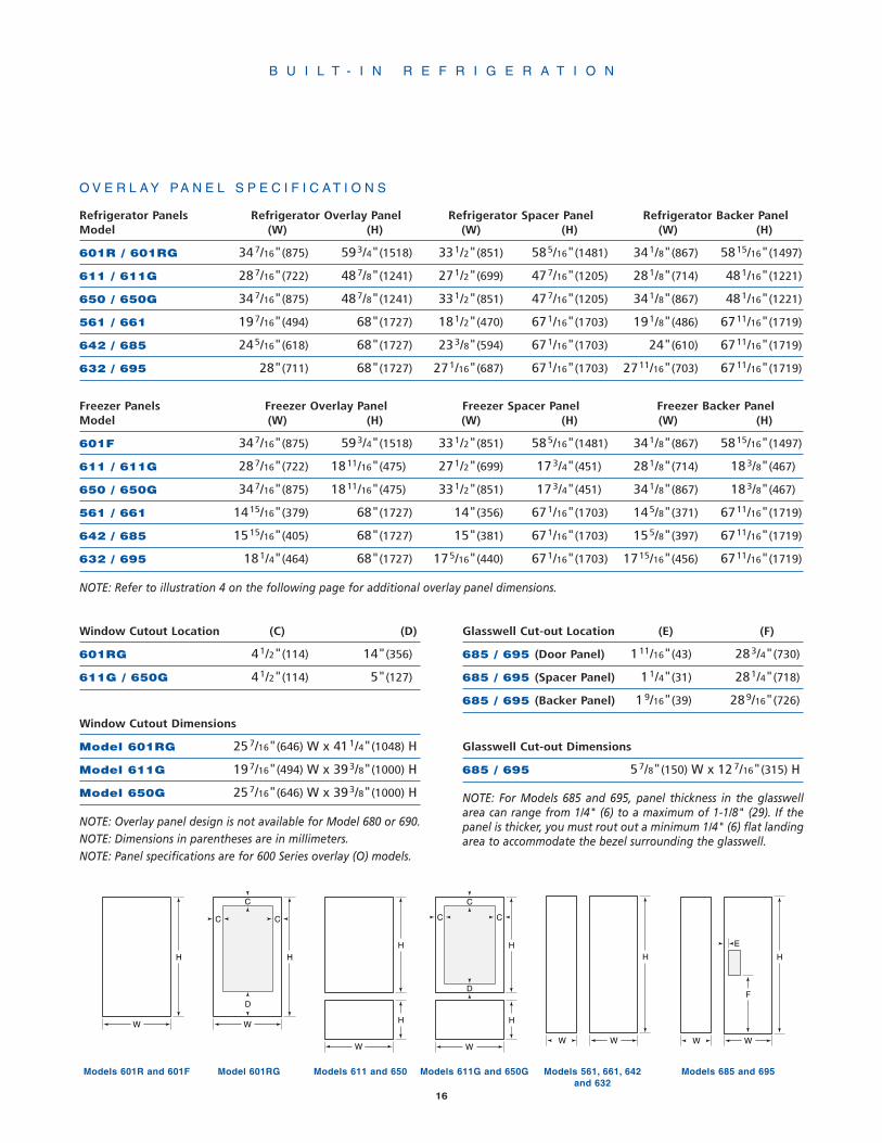
O V E R L A Y P A N E L S P E C I F I C A T I O N S
Refrigerator Panels Refrigerator Overlay Panel Refrigerator Spacer Panel Refrigerator Backer PanelModel (W) (H) (W) (H) (W) (H)
601R / 601RG 347/16"(875) 593/4"(1518) 331/2"(851) 585/16"(1481) 341/8"(867) 5815/16"(1497)
611 / 611G 287/16"(722) 487/8"(1241) 271/2"(699) 477/16"(1205) 281/8"(714) 481/16"(1221)
650 / 650G 347/16"(875) 487/8"(1241) 331/2"(851) 477/16"(1205) 341/8"(867) 481/16"(1221)
561 / 661 197/16"(494) 68"(1727) 181/2"(470) 671/16"(1703) 191/8"(486) 6711/16"(1719)
642 / 685 245/16"(618) 68"(1727) 233/8"(594) 671/16"(1703) 24"(610) 6711/16"(1719)
632 / 695 28"(711) 68"(1727) 271/16"(687) 671/16"(1703) 2711/16"(703) 6711/16"(1719)
Freezer Panels Freezer Overlay Panel Freezer Spacer Panel Freezer Backer PanelModel (W) (H) (W) (H) (W) (H)
601F 347/16"(875) 593/4"(1518) 331/2"(851) 585/16"(1481) 341/8"(867) 5815/16"(1497)
611 / 611G 287/16"(722) 1811/16"(475) 271/2"(699) 173/4"(451) 281/8"(714) 183/8"(467)
650 / 650G 347/16"(875) 1811/16"(475) 331/2"(851) 173/4"(451) 341/8"(867) 183/8"(467)
561 / 661 1415/16"(379) 68"(1727) 14"(356) 671/16"(1703) 145/8"(371) 6711/16"(1719)
642 / 685 1515/16"(405) 68"(1727) 15"(381) 671/16"(1703) 155/8"(397) 6711/16"(1719)
632 / 695 181/4"(464) 68"(1727) 175/16"(440) 671/16"(1703) 1715/16"(456) 6711/16"(1719)
NOTE: Refer to illustration 4 on the following page for additional overlay panel dimensions.
Models 611G and 650G
Window Cutout Location (C) (D)
601RG 41/2"(114) 14"(356)
611G / 650G 41/2"(114) 5"(127)
Window Cutout Dimensions
Model 601RG 257/16"(646) W x 411/4"(1048) H
Model 611G 197/16"(494) W x 393/8"(1000) H
Model 650G 257/16"(646) W x 393/8"(1000) H
NOTE: Overlay panel design is not available for Model 680 or 690.NOTE: Dimensions in parentheses are in millimeters.NOTE: Panel specifications are for 600 Series overlay (O) models.
Glasswell Cut-out Location (E) (F)
685 / 695 (Door Panel) 111/16"(43) 283/4"(730)
685 / 695 (Spacer Panel) 11/4"(31) 281/4"(718)
685 / 695 (Backer Panel) 19/16"(39) 289/16"(726)
Glasswell Cut-out Dimensions
685 / 695 57/8"(150) W x 127/16"(315) H
Models 685 and 695
NOTE: For Models 685 and 695, panel thickness in the glasswellarea can range from 1/4" (6) to a maximum of 1-1/8" (29). If thepanel is thicker, you must rout out a minimum 1/4" (6) flat landingarea to accommodate the bezel surrounding the glasswell.

Overlay panels for Models 601R, 601RG, 601F, 611, 611G,650 and 650G will require a recessed area to prevent theunit's lower hinge plate from hitting the door panel. Referto illustration 5 below.
For glass door Models 601RG, 611G and 650G, the refriger-ator door panel must include a cut-out to accommodate thewindow. Refer to the Overlay Panel Specifications chart andillustrations on the previous page.
IMPORTANT NOTE: On glass door models, the glass por-tion of the door must be exposed and not covered by anypart of the panel.
For Models 685 and 695, the refrigerator door panel mustinclude a cut-out to accommodate the glasswell and bezel.The thickness of the panel in this area can range from 1/4"(6) to a maximum of 1-1/8" (29). If the panel is thicker, pro-visions must be made to rout out a space to accommodatethe decorative bezel surrounding the glasswell.
For Models 685 and 695, adequate clearance under therefrigerator door handle is required to assure proper accessto the glasswell. Refer to the full-scale illustration at theend of this section for the proper mounting placement ofthe refrigerator door handle.
To install overlay panels, see the detailed procedures out-lined in the Sub-Zero 600 Series Installation Guide.
17
B U I L T - I N R E F R I G E R A T I O N
Dimensions in parentheses are in millimeters unless otherwise specified.
CAUTION
Do not exceed the overlay decorative panel dimensionslisted for Models 611, 611G, 650 or 650G. If you try tomake the reveal tighter between the door and drawerpanels, the panels may hit when opening and closing,causing possible damage to the panels and the unit.
1/4″(6) Backer Panel
Overlay Panel
3″(76)
Bottom Edge –Hinge Side(rear view)
Spacer Panel
3/8"(10)
1/2"(13)
Illus. 5
O V E R L A Y D O O R P A N E L S
If you and your client have ordered an overlay designmodel, you will be adding panels to give the unit the cus-tom Sub-Zero look. For exact door panel dimensions for 600Series overlay units, refer to the Overlay Panel Specificationschart and illustrations on the previous page. The overlaypanel design option is available on all 600 Series unitsexcept Models 680 and 690.
The overlay design line allows decorative panels to coverthe door trim for a more seamless appearance that blendswith the design of the room. To achieve this look, the mostcommon way is to work with three panels – the decorativeoverlay panel, a 0.10" (3) spacer panel and a 1/4" (6)backer panel. Depending on your cabinet manufacturer, thiscould be one panel routed for different dimensions or morelikely, three different panels.
Regardless of the physical construction of the panels (rout-ing or three panel assembly), you will need to follow theOverlay Panel Specifications charts and illustrations forexact sizing and panel placement to ensure a proper fit.
Illustration 3 is a cross section view of the three panelassembly showing placement of the door /drawer/grilletrim. Illustration 4 shows a rear view of the three panelassembly and critical dimensions, standard for all models.
IMPORTANT NOTE: The weight of each panel assemblycannot exceed 50 lbs (23 kg). The total thickness of allpanels for an overlay model must be at least 5/8" (16) thick.
IMPORTANT NOTE: Keep in mind that the Sub-Zero doorpanels have the potential for hitting adjacent cabinets and/or countertops when they are opened. You need to beaware of your surrounding cabinetry and space limitations.Refer to the full-scale illustrations at the end of this section.
Door/Drawer/Grille Trim1/16" (2)
5/32" (4)
1/4" (6) Backer Panel5/16" (8) min
.10"(3)
Spacer Panel
Overlay Panel
Spacer PanelOverlay Panel
1/4" (6)
BackerPanel
.10" (3)
~3/4"(19)
Illus. 3 Illus. 4

O V E R L A Y G R I L L E P A N E L S
Overlay grille panels match the design of the door panels.This option is available on all 600 Series units except Mod-els 601R, 601RG and 601F. Keep in mind that the overlaydoor panel design option is not available on Model 680 and690 doors; however the overlay grille panel is optional onthe framed application for these models. Refer to the chartsbelow for panel specifics. Also refer to illustration 4 on theprevious page for additional overlay panel dimensions.
Overlay Spacer BackerModel Panel (W) Panel (W) Panel (W)
611 / 611G 287/16"(722) 271/2"(699) 283/16"(716)
650 / 650G 347/16"(875) 331/2"(851) 343/16"(868)
561 / 661 347/16"(875) 331/2"(851) 343/16"(868)
642 407/16"(1027) 391/2"(1003) 403/16"(1021)
680 / 685 407/16"(1027) 391/2"(1003) 403/16"(1021)
632 467/16"(1180) 451/2"(1156) 463/16"(1173)
690 / 695 467/16"(1180) 451/2"(1156) 463/16"(1173)
Overlay Spacer BackerGrille Height Panel (H) Panel (H) Panel (H)
10" Grille 91/4"(235) 85/16"(211) 815/16"(227)
11" Grille* 101/4"(260) 95/16"(237) 915/16"(252)
12" Grille 111/4"(286) 105/16"(262) 1015/16"(278)
13" Grille 121/4"(311) 115/16"(287) 1115/16"(303)
14" Grille 131/4"(337) 125/16"(313) 1215/16"(329)
15" Grille 141/4"(362) 135/16"(338) 1315/16"(354)
*The 11" (279) high grille is standard on overlay models.
18
B U I L T - I N R E F R I G E R A T I O N
CAUTION
Do not exceed the panel dimensions listed for theappropriate overlay grille panel you are specifying. Theoverlay decorative panel cannot be any larger or it mayrestrict the air flow to the compressor area and causeproblems with the operation of the Sub-Zero unit.
Dimensions in parentheses are in millimeters unless otherwise specified.
H A R D W A R E C O N S I D E R A T I O N S
Overlay units come without handle hardware. The beauty ofthis design is that you can match the surrounding cabinethardware. You or the cabinet manufacturer must providehandle hardware to match the overall decor. However, youcan order handles from Sub-Zero as optional accessories.
The handle hardware must be installed before installing thepanel assembly. Use larger D-style handles. If screws withthick heads are used, the screws will need to countersunkinto the door before the panel is put into place.
IMPORTANT NOTE: Sub-Zero does not recommend usingsingle pull knobs on any of its 600 Series units.
Optional stainless steel handles are available in a variety ofdiameters and lengths, as well as handles to match thecolor and style of Wolf ovens. Contact your Sub-Zero dealerfor specifics.
Refer to the full-scale illustrations at the end of this sectionfor handle hardware considerations.
S I D E P A N E L S
When planning for side panels with the installation of the600 Series unit, you need to be aware of space configura-tion to achieve a pleasing fit. Depending on the exact panelyou are using with your unit, the height of the panel willvary. Refer to illustration 5 for placement of cut-outs aroundthe kickplate and grille area and remember that the dimen-sion to the back of the main frame is 23-7/8" (606).
3" (76)
1/4" (6)
237/8"(606)
1/4" (6)
3" (76)
4" (102)
131/4" (337)
Illus. 5

19
P L U M B I N G
For units with an automatic ice maker, rough in the watersupply line. Connect a 1/4" OD copper line to the housesupply, being sure to use an easily accessible shut off valvebetween the supply and the refrigerator.
Do not use self-piercing valves. A saddle valve kit (partnumber 4200880) is available from your Sub-Zero dealer.
IMPORTANT NOTE: A line filter is required when waterconditions have a high sediment content. The ice makeroperates on water pressure of 20 psi (1.4 bar) to 100 psi(6.9 bar). In some cases a reverse osmosis water filter sys-tem may not be able to maintain the minimum water pres-sure consistently.
The water line should be routed up through the floor with-in 1/2" (13) from the back wall and no higher than 3" (76)off the floor. If you have to come through the wall, makesure the water line is no more than 3" (76) from the floor.
Regardless of the routing, allow 3' (1 m) of excess coppertubing to remain outside the wall or floor for easy connec-tion to the unit. Refer to the Pre-Installation Specificationsillustrations and charts on pages 11 and 12 for exact spec-ifications.
E L E C T R I C A L
A 115 volt, 60 Hz, 15-amp electrical supply is required. Thesupply circuit for this appliance must be protected by a 15-amp fuse or circuit breaker. It is recommended that a sepa-rate circuit, serving only this appliance, be provided.
All Sub-Zero 600 Series units are equipped with a 6' (1.8 m)power supply cord with a 3-prong grounding plug and itmust be plugged into a mating 3-prong grounding type wallreceptacle. Follow the National Electrical Code and localcodes and ordinances when installing the receptacle. Referto the Pre-Installation Specifications illustrations and chartson pages 11 and 12 for exact specifications.
A N T I - T I P B L O C K I N G K I T
To prevent the unit from tipping forward and provide a sta-ble installation, the unit must be secured in place with ananti-tip blocking kit. If there is a solid soffit above the unitwith clearance between the unit and the soffit of 1" (25) orless, you won't need to block the unit. But for installationswith clearances of more than 1" (25), you must block theunit with the anti-tip blocking kit (wood block and hard-ware) provided with each Sub-Zero 600 Series unit. Refer tothe 600 Series Installation Guide packed with the appliance,which provides step-by-step procedures for making sure theunit is installed properly.
S E R V I C E I N F O R M A T I O N
If your client needs service, advise them to locate the modeland serial number on the plate at the top frame of the unitinside the door. Also advise your client to fill out productregistration forms and return to the factory, to assure thecustomer is in our database. Contact a Sub-Zero FactoryAuthorized Service Center, your dealer, or Sub-Zero FreezerCompany, Customer Service Department, at PO Box 44130,Madison, WI 53744-4130, call (800) 222-7820, or e-mail usat [email protected].
Dimensions in parentheses are in millimeters unless otherwise specified.
B U I L T - I N R E F R I G E R A T I O N
20
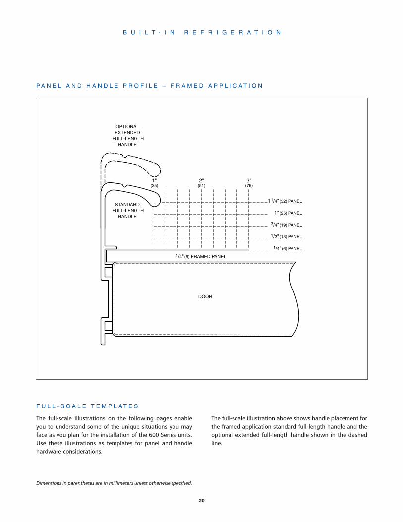
11/4" (32) PANEL
1"(25) PANEL
1/4" (6) PANEL
1/2" (13) PANEL
3/4" (19) PANEL
OPTIONALEXTENDED
FULL-LENGTHHANDLE
STANDARD FULL-LENGTH
HANDLE
DOOR
1/4" (6) FRAMED PANEL
1"(25)
2"(51)
3"(76)
F U L L - S C A L E T E M P L A T E S
The full-scale illustrations on the following pages enableyou to understand some of the unique situations you mayface as you plan for the installation of the 600 Series units.Use these illustrations as templates for panel and handlehardware considerations.
The full-scale illustration above shows handle placement forthe framed application standard full-length handle and theoptional extended full-length handle shown in the dashedline.
B U I L T - I N R E F R I G E R A T I O N
P A N E L A N D H A N D L E P R O F I L E – F R A M E D A P P L I C A T I O N
Dimensions in parentheses are in millimeters unless otherwise specified.

21
11/4" (32) PANEL
1" (25) PANEL
1/4" (6) PANEL
1/2" (13) PANEL
3/4" (19) PANEL5/8" (16) PANEL
DOOR
1/4" (6) APPROXIMATE THICKNESS OF WRAPPED STAINLESS STEEL DOOR
NOTE: FOR OVERLAY APPLICATIONS, OPTIONAL STAINLESS STEEL HANDLEMUST BE MOUNTED ON PANEL MINIMUM 5/8" (16) THICK.
1"2"
(51)3"
(76)
STANDARD STAINLESS STEEL HANDLE
The full-scale illustration above shows handle placement forthe standard stainless steel handle on the wrapped stain-less steel door and on overlay panel applications shown inthe dashed line.
B U I L T - I N R E F R I G E R A T I O N
IMPORTANT NOTE: For overlay applications, the optionalstainless steel handle must be must be mounted on a min-imum 5/8" (16) thick panel.
For overlay applications, mount door handles close to theopening edge of the door for ease of opening.
PA N E L A N D H A N D L E P R O F I L E – O V E R L A Y A N D S TA I N L E S S S T E E L A P P L I C AT I O N S
Dimensions in parentheses are in millimeters unless otherwise specified.

B U I L T - I N R E F R I G E R A T I O N
22
2" (51)
1" (25)
STAINLESS STEELHANDLE PROFILE
GLASSWELL PROFILE – MODELS 685 AND 695
REFRIGERATOR DOOR PROFILE – TOP VIEW
DOOR
NOTE: FOR OVERLAY APPLICATIONS, OPTIONAL STAINLESS STEEL HANDLEMUST BE MOUNTED ON PANEL MINIMUM 5/8" (16) THICK.
The full-scale illustration above shows proper placement ofthe stainless steel handle for the Models 685 and 695refrigerator door in an overlay application. Adequate clear-ance is required under the handle to assure proper accessto the glasswell.
H A N D L E P L A C E M E N T F O R M O D E L S 6 8 5 A N D 6 9 5 – O V E R L A Y A P P L I C A T I O N
Dimensions in parentheses are in millimeters unless otherwise specified.

B U I L T - I N R E F R I G E R A T I O N
The full-scale illustration above shows the panel and handleprofile for 130˚ door opening with a 2" (51) filler strip.
Interference of door panels with handles at maximum doorswing may require the use of an optional 90˚ door stopavailable through your Sub-Zero dealer.
23
11 /4"
(32) PA
NEL
1" (2
5) PA
NEL
*1/4"
(6) P
ANEL
1 /2" (1
3) PA
NEL
3 /4" (1
9) PA
NEL
130˚ DOOR OPENINGWITH 2" (51) FILLER STRIP
(TOP VIEW)
OPTIONALEXTENDED
FULL-LENGTHHANDLE
STANDARD FULL-LENGTH
HANDLE
DOOR CLOSED
DOOR OPEN @ 130˚
HINGE
2" (51)
FILLER STRIP
MAIN FRAME
ALLOW FOR FILLER LAPBEHIND FLANGE
OPTIONALSTAINLESS
STEELHANDLE
OVERLAY PANEL3/4" (19) THICK
(NOMINAL)
SUB-ZERO UNITSUB-ZERO UNIT
P A N E L A N D H A N D L E P R O F I L E – 1 3 0 ˚ D O O R O P E N I N G
*Approximate thickness of wrapped stainless steel door.
Dimensions in parentheses are in millimeters unless otherwise specified.

24
11 /
4" (3
2) P
AN
EL
1" (2
5) P
AN
EL
*1/4
" (6
) PA
NE
L
1 /2"
(13)
PA
NE
L
3 /4"
(19)
PA
NE
L
11/4" (32)
11/2" (38)
13/4" (44)
0" (0)
1" (25)
2" (51)
21/4" (57)
21/2" (63)
23/4" (70)
3" (76)
31/4" (83)
31/2" (89)
1/4" (6)
1/2" (25)
3/4" (19)HINGE
OVERLAY PANEL3/4" (19) THICK (NOMINAL)
DOOR CLOSED
DOOR OPEN @ 90˚
90˚ DOOR OPENING(TOP VIEW)
MAIN FRAME
NOMINAL OVERALLWIDTH OF SUB-ZERO
SUB-ZERO UNIT
237/8" (606) TO REAROF SUB-ZERO
O V E R L A Y P A N E L A P P L I C A T I O N – 9 0 ˚ D O O R O P E N I N G
The full-scale illustration above shows what considerationsyou need to make for overlay panel applications, and howthey may interact with adjacent cabinets and countertops.
Dimensions in parentheses are in millimeters unless otherwise specified.
B U I L T - I N R E F R I G E R A T I O N
*Approximate thickness of wrapped stainless steel door.
25
Model 700BRBase Refrigerator
Model 700TFTall Freezer
Model 700TCTall Combination
Model 700TRTall Refrigerator
Model 700BFBase Freezer
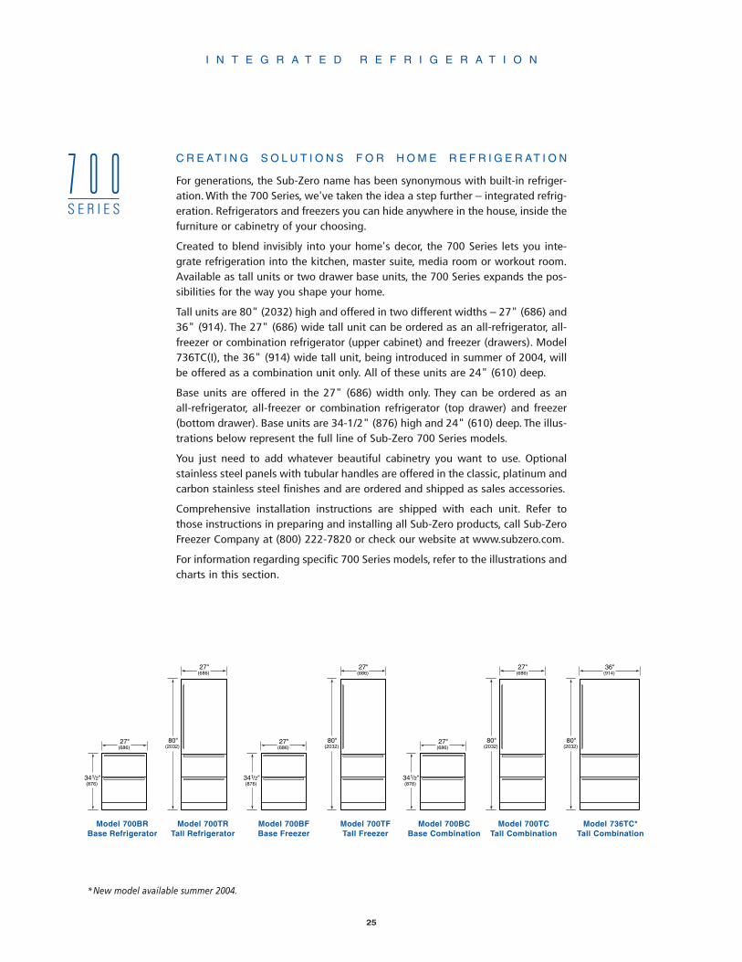
C R E AT I N G S O L U T I O N S F O R H O M E R E F R I G E R AT I O N
For generations, the Sub-Zero name has been synonymous with built-in refriger-ation. With the 700 Series, we've taken the idea a step further – integrated refrig-eration. Refrigerators and freezers you can hide anywhere in the house, inside thefurniture or cabinetry of your choosing.
Created to blend invisibly into your home's decor, the 700 Series lets you inte-grate refrigeration into the kitchen, master suite, media room or workout room.Available as tall units or two drawer base units, the 700 Series expands the pos-sibilities for the way you shape your home.
Tall units are 80" (2032) high and offered in two different widths – 27" (686) and36" (914). The 27" (686) wide tall unit can be ordered as an all-refrigerator, all-freezer or combination refrigerator (upper cabinet) and freezer (drawers). Model736TC(I), the 36" (914) wide tall unit, being introduced in summer of 2004, willbe offered as a combination unit only. All of these units are 24" (610) deep.
Base units are offered in the 27" (686) width only. They can be ordered as anall-refrigerator, all-freezer or combination refrigerator (top drawer) and freezer(bottom drawer). Base units are 34-1/2" (876) high and 24" (610) deep. The illus-trations below represent the full line of Sub-Zero 700 Series models.
You just need to add whatever beautiful cabinetry you want to use. Optionalstainless steel panels with tubular handles are offered in the classic, platinum andcarbon stainless steel finishes and are ordered and shipped as sales accessories.
Comprehensive installation instructions are shipped with each unit. Refer tothose instructions in preparing and installing all Sub-Zero products, call Sub-ZeroFreezer Company at (800) 222-7820 or check our website at www.subzero.com.
For information regarding specific 700 Series models, refer to the illustrations andcharts in this section.
I N T E G R A T E D R E F R I G E R A T I O N
7 0 0S E R I E S
27"(686)
80"(2032)
341/2"(876)
27"(686)
27"(686)
80"(2032)
341/2"(876)
27"(686)
36"(914)
80"(2032)
27"(686)
80"(2032)
341/2"(876)
27"(686)
Model 700BCBase Combination
Model 736TC*Tall Combination
*New model available summer 2004.

I N T E G R A T E D R E F R I G E R A T I O N
26
Model 700TR
SPECIFICATIONS
Tall Refrigerator Unit
27"W x 80"H x 24"D(686 x 2032 x 610)
Refrigerator Capacity15.5 cu ft (439 L)
Minimum Height Required791/2" (2019)
Door Swing Clearance251/2" (648)
Specify LH or RH Door Swing
Drawer Clearance191/2" (495)
Annual Energy Usage428 kWh / $35*
Shipping Weight360 lbs (163 kg)
PANEL OPTIONS
Integrated
Classic, Platinum or CarbonStainless Steel Finish
FEATURES
2 Temperature Zones
3 Adjustable Glass Shelves
1 Stationary Shelf
2 Storage Drawers
Removable Crisper Cover
Adjustable Deli Drawer
3 Adjustable Door Shelves
Adjustable Dairy Compartment
Egg Container
Model 700BR
SPECIFICATIONS
Base Refrigerator Unit
27"W x 341/2"H x 24"D(686 x 876 x 610)
Refrigerator Capacity5.3 cu ft (150 L)
Minimum Height Required34" (864)
Drawer Clearance191/2" (495)
Annual Energy Usage358 kWh / $30*
Shipping Weight190 lbs (86 kg)
PANEL OPTIONS
Integrated
Classic, Platinum or CarbonStainless Steel Finish
FEATURES
2 Temperature Zones
2 Storage Drawers
Removable Crisper Cover
Model 700TF
MODEL OPTIONS
700TFI Automatic Ice Maker
SPECIFICATIONS
Tall Freezer Unit
27"W x 80"H x 24"D(686 x 2032 x 610)
Freezer Capacity15.3 cu ft (433 L)
Minimum Height Required791/2" (2019)
Door Swing Clearance251/2" (648)
Specify LH or RH Door Swing
Drawer Clearance191/2" (495)
Annual Energy Usage655 kWh / $54*
Shipping Weight360 lbs (163 kg)
PANEL OPTIONS
Integrated
Classic, Platinum or CarbonStainless Steel Finish
FEATURES
1 Temperature Zone
3 Adjustable Glass Shelves
1 Stationary Shelf
2 Storage Drawers
4 Adjustable Door Shelves
Automatic Ice Maker(Model 700TFI)
Automatic Defrost
Model 700TRModel 700BR Model 700TF
Model 700BF
MODEL OPTIONS
700BFI Automatic Ice Maker
SPECIFICATIONS
Base Freezer Unit
27"W x 341/2"H x 24"D(686 x 876 x 610)
Freezer Capacity5.1 cu ft (144 L)
Minimum Height Required34" (864)
Drawer Clearance191/2" (495)
Annual Energy Usage491 kWh / $41*
Shipping Weight190 lbs (86 kg)
PANEL OPTIONS
Integrated
Classic, Platinum or CarbonStainless Steel Finish
FEATURES
1 Temperature Zone
2 Storage Drawers
Automatic Ice Maker(Model 700BFI)
Automatic Defrost
Model 700BF

I N T E G R A T E D R E F R I G E R A T I O N
27
Model 700TC
MODEL OPTIONS
700TCI Automatic Ice Maker
SPECIFICATIONS
Tall Combination Unit
27"W x 80"H x 24"D(686 x 2032 x 610)
Refrigerator Capacity10.2 cu ft (289 L)
Freezer Capacity5.1 cu ft (144 L)
Minimum Height Required791/2" (2019)
Door Swing Clearance251/2" (648)
Specify LH or RH Door Swing
Drawer Clearance 191/2" (495)
Annual Energy Usage544 kWh / $45*
Shipping Wt 360 lbs (163 kg)
PANEL OPTIONS
Integrated
Classic, Platinum or CarbonStainless Steel Finish
FEATURES
Refrigerator
Refrigerator Temperature Zone
3 Adjustable Glass Shelves
1 Stationary Shelf
Adjustable Deli Drawer
3 Adjustable Door Shelves
Adjustable Dairy Compartment
Egg Container
Freezer
Freezer Temperature Zone
2 Storage Drawers
Automatic Ice Maker (700TCI)
Automatic Defrost
Model 736TCAvailable Early Fall 2004
MODEL OPTIONS
736TCI Automatic Ice Maker
SPECIFICATIONS
Tall Combination Unit
36"W x 80"H x 24"D(914 x 2032 x 610)
Refrigerator Capacity13.4 cu ft (379 L)
Freezer Capacity6.9 cu ft (195 L)
Minimum Height Required791/2" (2019)
Door Swing Clearance341/2" (876)
Specify LH or RH Door Swing
Drawer Clearance 191/2" (495)
Annual Energy Usage573 kWh / $48*
Shipping Wt 480 lbs (218 kg)
PANEL OPTIONS
Integrated
Classic, Platinum or CarbonStainless Steel Finish
FEATURES
Refrigerator
Refrigerator Temperature Zone
3 Adjustable Glass Shelves
1 Stationary Shelf
Adjustable Deli Drawer
3 Adjustable Door Shelves
Adjustable Dairy Compartment
Egg Container
Freezer
Freezer Temperature Zone
2 Storage Drawers
Automatic Ice Maker (736TCI)
Automatic Defrost
Model 700TC Model 736TC
Model 700BC
MODEL OPTIONS
700BCI Automatic Ice Maker
SPECIFICATIONS
Base Combination Unit
27"W x 341/2"H x 24"D(686 x 876 x 610)
Refrigerator Capacity2.9 cu ft (82 L)
Freezer Capacity2.1 cu ft (59 L)
Minimum Height Required34" (864)
Drawer Clearance191/2" (495)
Annual Energy Usage451 kWh / $37*
Shipping Weight190 lbs (86 kg)
PANEL OPTIONS
Integrated
Classic, Platinum or CarbonStainless Steel Finish
FEATURES
Refrigerator
Refrigerator Temperature Zone
1 Storage Drawer
Removable Crisper Cover
1 Removable Drawer Divider
Freezer
Freezer Temperature Zone
1 Storage Drawer
Automatic Ice Maker(Model 700BCI)
Automatic Defrost
Model 700BC
*Annual energy costs are basedon 8.29 cents per kilowatt hour.
Optional stainless steel panelsare ordered and shipped as salesaccessories and include tubularstainless steel handles.
Optional panel finishes –(S) Classic stainless steel(P) Platinum stainless steel(B) Carbon stainless steel
Dimensions in parentheses arein millimeters unless otherwisespecified.
7 0 0S E R I E S
28
I N T E G R A T E D R E F R I G E R A T I O N
F E A T U R E S A N D O P T I O N S
Sub-Zero's industry leadership is evident in this newapproach to residential refrigeration. Our tradition of excel-lence is evident in all of these features and options.
All 700 Series units are offered as integrated or stainlesssteel. Optional stainless steel panels and handles are avail-able in the classic, platinum and carbon stainless steel fin-ishes and are ordered and shipped as sales accessories.
Functional Design. These units can be placed anywhere inthe home. Think about "point-of-use refrigeration" whenplanning where to place your units.
Built-in Design. All Sub-Zero units are 24" (610) deep.Tall 700 Series units are 80" (2032) high and offered in twodifferent widths – 27" (686) and 36" (914). All base unitsare 27" (686) wide and 34-1/2" (876) high.
Microprocessor. The "brains" of the 700 Series units, thiscomputer allows the best in temperature control, efficiencyand food preservation.
Temperature Zones. On the tall and base refrigerator andcombination units, you have the flexibility of having twotemperatures within the same unit.
Automatic Defrost. Depending on usage and exact cli-mate, the 700 Series unit will adapt to the unique situationand adjust accordingly to offer greater efficiency. 700 Seriesfreezer and combination units have an automatic defrostsystem.
Kickplate. The adjustable solid kickplate meets standardsof the American Institute of Architects. The toe kick area fora solid, decorative kickplate is 4" (102) high by 3" (76)deep. You can show a 10" (254) toe kick, but you cannotcover the louvers of the kickplate. If you choose, the kick-plate can be painted.
Front Venting. All units have the mechanical equipment inan area below the lower drawer. The lower drawer panelcan extend to cover these louvers, but a removable decora-tive kickplate cannot cover the fins.
Lighting. Flat to the ceiling, superior lighting provideswhite, efficient light in cabinet and drawer units.
Door/Drawer Alarm. If your door or drawer is accidental-ly left open for more than 30 seconds an audible alarm willsound.
Spill-Proof Shelves. The cabinet section of the tall unitsfeature adjustable spill-proof one piece glass shelves thatare easily removed for cleaning.
Dairy Shelf. This magnetically sealed compartment is fullyadjustable on the tall refrigerator and combination units.
Crisper Cover. On the tall and base refrigerator units andthe base combination unit, a removable crisper cover isoffered for one of the drawer sections.
Deli-Drawer. Smaller items are not lost in this handy fea-ture of the tall refrigerator and tall combination units.
Egg Tray. You can store a dozen eggs in this removable eggtray with the tall refrigerator and tall combination units.
Ice Maker. An automatic ice maker, providing crescent-shaped ice, is available as an option on the tall and basefreezers as well as the tall and base combination units. Thisoptional equipment must be factory installed.
Door Swing. You can choose left or right door swing on thetall units. This option must be ordered when requesting theunit. You cannot reverse the door in the field.
Dual Action Hinge. An exclusive dual action hinge is fea-tured on all of the tall units.
Door Stop. On all of the tall units, a 90˚ door stop is builtin to the hinge. Normal door swing is 105˚.
Dimensions in parentheses are in millimeters unless otherwise specified.

29
I N T E G R A T E D R E F R I G E R A T I O N
Dimensions are in inches with millimeters in parentheses.
O V E R A L L S I Z E S P E C I F I C A T I O N S
In trying to understand the different 700 Series units avail-able, keep in mind the three size configurations:
• Base Units – 27"W x 341/2"H x 24"D (686 x 876 x 610)
• 27" (686) Wide Tall Units –27"W x 80"H x 24"D (686 x 2032 x 610)
• 36" (914) Wide Tall Units –36"W x 80"H x 24"D (914 x 2032 x 610)
The height of the tall unit is set at 80" (2032).You can allowthe top of the door panel to exceed this dimension withcaution. If you are working with 84" (2134) or 96" (2438)neighboring panels, you can utilize door panels to matchthis height. Other critical dimensions regarding the doorswing, drawer openings and toe kick clearance are noted inthe Overall Dimensions illustrations on the following pages.
Temperature Zones. With the microprocessor in the 700Series units, you have the capability of setting differentoptimum temperatures.
• Model 700BR has two zones with a 34˚F (1˚C) to 45˚F(7˚C) temperature range in the top drawer, the bottomdrawer range is 0 to 3 degrees colder than the top drawer.
• Model 700TR has two zones with a 34˚F (1˚C) to 45˚F(7˚C) temperature range in each.
• Model 700BF(I) has one zone with a -5˚F (-21˚C) to +5˚F(-15˚C) temperature range.
• Model 700TF(I) has one zone with a -5˚F (-21˚C) to +5˚F(-15˚C) temperature range.
• Model 700BC(I) has two zones, with a 34˚F (1˚C) to 45˚F(7˚C) temperature range in the top drawer and -5˚F (-21˚C)to +5˚F (-15˚C) in the bottom drawer.
• Models 700TC(I) and 736TC(I) have two zones, with a34˚F (1˚C) to 45˚F (7˚C) temperature range in the cabinetand -5˚F (-21˚C) to +5˚F (-15˚C) in the drawers.
Sub-Zero Warranty. Like all Sub-Zero units, the 700 Seriesis covered by the Sub-Zero Freezer Company Products Lim-ited Warranty, exclusions apply. See page 70 for details.

30
I N T E G R A T E D R E F R I G E R A T I O N
Dimensions in parentheses are in millimeters unless otherwise specified.
DRAWER MOUNTING DETAIL
341/2"*(876)
*1/2" (13) +_ ADJUSTMENT IN LEVELING LEGS
FRONT VIEW
3/8"(10)
131/4"(337)1/2"
(13)
101/4"(260)
203/8"(518)
27"(686)
(UNIT DIMENSION)
*DRAWER PANEL THICKNESS NOT INCLUDED
DRAWER CLOSED
191/2"*(495)
24"(610)
257/8" (657)
TOP VIEW
O V E R A L L D I M E N S I O N S – B A S E U N I T S2 7 " ( 6 8 6 ) W I D E
TOP OFROUGH
OPENING
789/16"*(1995)
341/2"*(876)
14"(356)
13/16"(21)
93/4"(248)
4"(102)
80"*(2032)
27"(686)
24"(610)
*1/2" (13) +_ ADJUSTMENT IN LEVELING LEGS
FRONT VIEW SIDE VIEW
(UNIT DIMENSION) (UNIT DIMENSION)
3/8"(10)
131/4"(337)1/2"
(13)
101/4"(260)
203/8"(518)
DOORMOUNTING
DETAIL
DRAWER MOUNTING DETAIL
105°90°
90° DOOR OPENING
DOOR/DRAWER CLOSED
MAXIMUM DOOR OPENING
*DOOR/DRAWER PANEL THICKNESS NOT INCLUDED – DIMENSION WILL VARY WITH INSTALLATION
DOOR/DRAWER CLOSED
191/2"*(495)251/2"*
(648)
24"(610)
257/8" (657)
45/8"* (117)TOP VIEW
O V E R A L L D I M E N S I O N S – T A L L U N I T S2 7 " ( 6 8 6 ) W I D E
93/4"(248)
4"(102) SIDE VIEW
24"(610)
(UNIT DIMENSION)

31
P L A N N I N G I N F O R M A T I O N
Before moving the 700 Series unit into place, be sure thatthe finished opening dimensions, electrical and plumbinglocations and minimum door and drawer clearances areaccurate. Refer to the Pre-Installation Specifications illus-trations for your 700 Series unit on the following pages. Besure your installer has this information before finishingwork is completed.
NOTE: 700 Series units without an automatic ice maker willnot require the plumbing connections shown in the Pre-Installation Specifications illustrations.
I N T E G R A T E D R E F R I G E R A T I O N
DOOR MOUNTINGDETAIL
DRAWER MOUNTINGDETAIL
TOP OFROUGH
OPENING
7713/16"*(1976)
341/2"*(876)
3/8"(10)
131/4"(337)1/2"
(13)
101/4"(260)
203/8"(518)
14"(356)
15/16"(33)
93/4"(248)
4"(102)
80"*(2032)
36"(914)
24"(610)
*1/2" (13) +_ ADJUSTMENT IN LEVELING LEGS
FRONT VIEW SIDE VIEW
(UNIT DIMENSION) (UNIT DIMENSION)
105°90°
90° DOOR OPENING
DOOR/DRAWERCLOSED
MAXIMUM DOOR OPENING
DOOR/DRAWERCLOSED
191/2"*(495)341/2"*
(876)
24"(610)
347/8" (886)
7"*(178)
*DOOR/DRAWER PANEL THICKNESS NOT INCLUDED – DIMENSION WILL VARY WITH INSTALLATION
TOP VIEW
O V E R A L L D I M E N S I O N S – T A L L U N I T S3 6 " ( 9 1 4 ) W I D E

25"(635)
27"(686)
341/2" (876)
27"(686)
25"(635) CL
ANTI-TIPBRACKET
WATER LINEBOTTOM ENTRY
LOCATION
WATER LINESIDE ENTRYLOCATIONS
11/2"(38)
11/2"(38)
27"(686)
11/2"(38)
151/2"(394)
9"(229)
131/2"(343) CL
131/2"(343)
ANTI-TIPBRACKET
6"(152)
TOP VIEW TOP VIEW
SIDE VIEWFRONT VIEW
WATER LINESIDE ENTRYLOCATIONANTI-TIP
BRACKETNOTE: ANTI-TIP BRACKET MUST BE INSTALLED TO
PREVENT UNIT FROM TIPPING FORWARD
41/2"(114)
21/2" (64)
151/2" (394)
3/4"(19)
3"(76)
1/4"(6)
13" (330) 9"(229)
ANTI-TIPBRACKET
LOCATE WATER LINE(REAR ENTRY) WITHIN
SHADED AREA
LOCATE ELECTRICAL WITHINSHADED AREA – ORIENT GROUND
PRONG TO RIGHT AS SHOWN
32
I N T E G R A T E D R E F R I G E R A T I O N
7 0 0S E R I E S
P R E - I N S T A L L A T I O N S P E C I F I C A T I O N S – 2 7 " ( 6 8 6 ) W I D E B A S E U N I T S
Dimensions in parentheses are in millimeters unless otherwise specified.
IMPORTANT NOTE: The depth of each 700 Series unitis 24" (610) from the front of the unit to its back. Yourdesign may necessitate moving the unit back, or cab-inets forward to achieve a flush fit. This will require aminimum rough opening depth of 25" (635). Refer tothe illustration.

33
I N T E G R A T E D R E F R I G E R A T I O N
25"(635)
27"(686)
80"(2032)
27"(686)
25"(635) CL
ANTI-TIPBRACKET
WATER LINEBOTTOM ENTRY
LOCATION
WATER LINESIDE ENTRYLOCATIONS
11/2"(38)
11/2"(38)
27"(686)
11/2"(38)
151/2"(394)
9"(229)
131/2"(343) CL
131/2"(343)
ANTI-TIPBRACKET
6"(152)
TOP VIEW TOP VIEW
SIDE VIEWFRONT VIEW
WATER LINESIDE ENTRYLOCATIONANTI-TIP
BRACKET
41/2"(114)
21/2" (64)
151/2" (394)
3/4"(19)
3"(76)
1/4"(6)
13" (330) 9"(229)
ANTI-TIPBRACKET
LOCATE WATER LINE(REAR ENTRY) WITHIN
SHADED AREA
LOCATE ELECTRICAL WITHINSHADED AREA – ORIENT GROUND
PRONG TO RIGHT AS SHOWN
NOTE: ANTI-TIP BRACKET MUST BE INSTALLED TO PREVENT UNIT FROM TIPPING FORWARD
P R E - I N S T A L L A T I O N S P E C I F I C A T I O N S – 2 7 " ( 6 8 6 ) W I D E T A L L U N I T S
7 0 0S E R I E S
IMPORTANT NOTE: The depth of each 700 Series unitis 24" (610) from the front of the unit to its back. Yourdesign may necessitate moving the unit back, or cab-inets forward to achieve a flush fit. This will require aminimum rough opening depth of 25" (635). Refer tothe illustration.
34
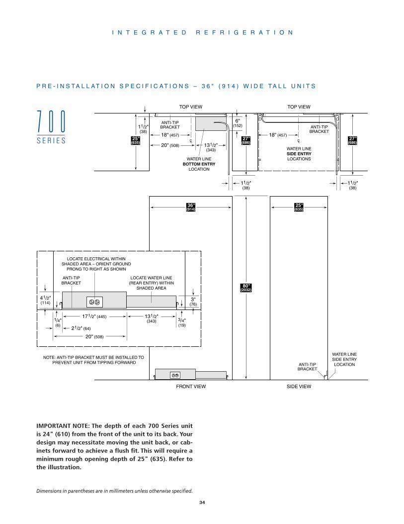
P R E - I N S T A L L A T I O N S P E C I F I C A T I O N S – 3 6 " ( 9 1 4 ) W I D E T A L L U N I T S
25"(635)
36"(914)
80"(2032)
27"(686)
25"(635) CL
ANTI-TIPBRACKET
WATER LINEBOTTOM ENTRY
LOCATION
WATER LINESIDE ENTRYLOCATIONS
11/2"(38)
11/2"(38)
27"(686)
11/2"(38)
20" (508) 131/2"(343)
18" (457)CL
ANTI-TIPBRACKET
18" (457)
6"(152)
TOP VIEW TOP VIEW
SIDE VIEWFRONT VIEW
WATER LINESIDE ENTRYLOCATIONANTI-TIP
BRACKET
21/2" (64)
20" (508)
3/4"(19)
3"(76)
171/2" (445) 131/2"(343)
ANTI-TIPBRACKET
NOTE: ANTI-TIP BRACKET MUST BE INSTALLED TO PREVENT UNIT FROM TIPPING FORWARD
41/2"(114)
1/4"(6)
LOCATE WATER LINE(REAR ENTRY) WITHIN
SHADED AREA
LOCATE ELECTRICAL WITHINSHADED AREA – ORIENT GROUND
PRONG TO RIGHT AS SHOWN
I N T E G R A T E D R E F R I G E R A T I O N
7 0 0S E R I E S
Dimensions in parentheses are in millimeters unless otherwise specified.
IMPORTANT NOTE: The depth of each 700 Series unitis 24" (610) from the front of the unit to its back. Yourdesign may necessitate moving the unit back, or cab-inets forward to achieve a flush fit. This will require aminimum rough opening depth of 25" (635). Refer tothe illustration.

35
I N T E G R A T E D R E F R I G E R A T I O N
F R A M E D C A B I N E T R Y
Framed cabinetry applications present you with differentquestions to address. The illustrations below show commonapplications of framed cabinetry. These are not meant to bethe only alternatives, but are suggestions from designersaround the country. Also refer to the full-scale illustrationsat the end of this section for specifics on door openings.
NOTE: In the illustrations below, the first width dimensionshown is for 27" (686) wide units and the second dimen-sion is for the Model 736TC(I).
SUB-ZEROUNIT
DOOR PANELCABINET DOOR
CABINET FRAME
TO WALL
24(610)
1/8" (10)REVEAL
36(914)
27(686)
OR
Traditional frame – full overlay (top view)
DOOR PANELCABINET DOOR
CABINET FRAME
SUB-ZEROUNIT TO WALL
24(610)
1/8" (10)REVEAL
36(914)
27(686)
OR
Traditional frame – standard overlay (top view)
DOOR PANELCABINET DOOR
CABINET FRAME
SUB-ZEROUNIT TO WALL
24(610)
1/8" (10)REVEAL
36(914)
27(686)
OR
Traditional frame – 3/8" (10) offset (top view)
C A B I N E T R Y A P P L I C A T I O N S
The 700 Series of refrigeration is compatible with virtuallyany style and look of cabinetry. The units can be used withframed as well as frameless cabinets. Because of the preciseapplication and the look you may want to achieve, there areimportant questions you need to answer before orderingpanels for the doors /drawers. As you look at styles of cabi-nets keep some important facts in mind:
Weight Limitations – The door panel cannot exceed40 lbs (18 kg) and each drawer panel must not exceed12 lbs (5 kg) for 27" (686) wide units. For Model 736TC(I)the door panel weight limit is 53 lbs (24 kg) and 16 lbs (7kg) for each drawer panel.
Panel Thickness – Door and drawer panels must be a min-imum of 5/8" (16) thick.
Panel Hardware – We recommend using D-style puIIs. Theyshould be located on the opposite side from the hinge, cen-tered on the cabinet door and the top, center area of thedrawer panel.
IMPORTANT NOTE: The depth of each 700 Series unitis 24" (610) from the front of the unit to its back. YouMUST allow for the thickness of the panel you areapplying when planning for the finished rough open-ing depth if you want the front panel to be flush withsurrounding cabinetry. You may have to move the unitback into drywall or bring the cabinets forward toachieve a flush fit.
The height of the door panel can grow beyond 45-1/4"(1149) and exceed the 80" (2032) overall height, as long asyou stay below the recommended door panel weight limit.
The toe kick clearance can vary with the height of the lowerdrawer panel, the maximum panel height is 16-9/16" (421).You must keep a minimum space of 4" (102) clear belowthe bottom edge of the lower drawer panel, so the unit canbe properly vented.

36
I N T E G R A T E D R E F R I G E R A T I O N
FRONT VIEW SIDE VIEW
27(686)121 (38)
3426 (679)
121 (38)
121
(38)
12
(38)
121
(38)
14 1316
3447
(1213)
4 (102)
24 (610)
84(2624)
1234
(876)
80*(2032)
NOTE: SHADED AREAINDICATES STATIONARYSTYLES AND RAILS.
A-ALL REVEALS ARE 1/4" (6)B-DRAWER RAILS ARE ATTACHED TO DRAWER FRONTSC-BOTTOM RAIL MUST BE REMOVEABLE
CA
A
A
B
B
*4(102)
TOP VIEW
A A
DOOR PANEL
CABINET DOOR
TO WALL
SUB-ZEROUNIT
27(686)
25(635)
*DIMENSIONS MAY VARY
13 716
(342)
(376)
PANEL WIDTH
*
NOTE: Cabinetry dimensions shown are for 27" (686) wide units. For Model 736TC(I) add 9" (229) to overall width dimensions.
F R A M E D C A B I N E T R Y –B E A D E D I N S E T A P P L I C A T I O N
The illustration below shows a 27" (686) wide 700 Seriesbase or tall unit installed within a framed cabinetry beadedinset application. Review with particular attention given tothe overall panel specifications.
IMPORTANT NOTE: Cabinetry dimensions shown are for27" (686) wide units. For Model 736TC(I) add 9" (229) tooverall width dimensions.

37
I N T E G R A T E D R E F R I G E R A T I O N
Dimensions are in inches with millimeters in parentheses.
SIDE VIEW
TOEKICK
FINISHED OPENING
*2634 (679)
34*79
(2026)
13 716
(341)
45 14
(1149)
*16 916
(421)
*4(102)
24(610)
27(686)
34 12
(876)
A
A
A
A-ALL REVEALS ARE 1/4" (6) * DIMENSIONS MAY VARY
80*(2032)
PANEL WIDTH
*
NOTE: Cabinetry dimensions shown are for 27" (686) wide units. For Model 736TC(I) add 9" (229) to overall width dimensions.
F R A M E L E S S C A B I N E T R Y
The illustration below shows a hypothetical installation of a27" (686) wide 700 Series base or tall unit within framelesscabinetry. Review with particular attention given to theoverall panel specifications. Also refer to the full-scale illus-trations at the end of this section for specifics on dooropenings.
IMPORTANT NOTE: Cabinetry dimensions shown are for27" (686) wide units. For Model 736TC(I) add 9" (229) tooverall width dimensions.

38
I N T E G R A T E D R E F R I G E R A T I O N
Panel width dimensions – single tall unit installation
2634 (679)
34 (19) PANEL
APPLIANCEDOOR WIDTH
SUB-ZEROUNIT
TO BACKOF UNIT
2578 (657)
27(686)
24(610)
CABINETRYOR SIDEPANEL
25(635)
CABINETRYOR SIDEPANEL
25(635)
18 (3)
REVEALmin*1
8 (3)
REVEALmin*
*SUBTRACT PANEL WIDTH FROM CABINETRY OPENING TO DETERMINE ACTUAL WIDTH OF REVEAL
P A N E L C O N S I D E R A T I O N S
IMPORTANT NOTE: The depth of each 700Series unit is 24" (610) from the front of theunit to its back. You MUST allow for thethickness of the panel you are applying whenplanning for the finished rough openingdepth if you want the front panel to be flushwith surrounding cabinetry. You may have tomove the unit back into drywall or bring thecabinets forward to achieve a flush fit.
The illustrations show panel width dimensions forinstallation of a single tall unit and installing twotall units side by side.
IMPORTANT NOTE: Cabinetry dimensions shownare for 27" (686) wide units. For Model 736TC(I)add 9" (229) to overall width dimensions.
Panel width dimensions – two tall units installed side by side
2634 (679)
34 (19) PANEL 3
4 (19) PANEL
DOOR
SUB-ZEROUNIT
DOOR
SUB-ZEROUNIT
2634 (679)
54 (1372)
TO BACKOF UNIT
24(610)
18 (3)
REVEALmin*1
8 (3)
REVEALmin*
18 (3)
REVEALmin*
*SUBTRACT PANEL WIDTH FROM CABINETRY OPENING TO DETERMINE ACTUAL WIDTH OF REVEAL
CABINETRYOR SIDEPANEL
25(635)
CABINETRYOR SIDEPANEL
25(635)
Dimensions are in inches with millimeters in parentheses.
NOTE: Cabinetry dimensions shown are for 27" (686) wide units. For Model736TC(I) add 9" (229) to overall width dimensions.
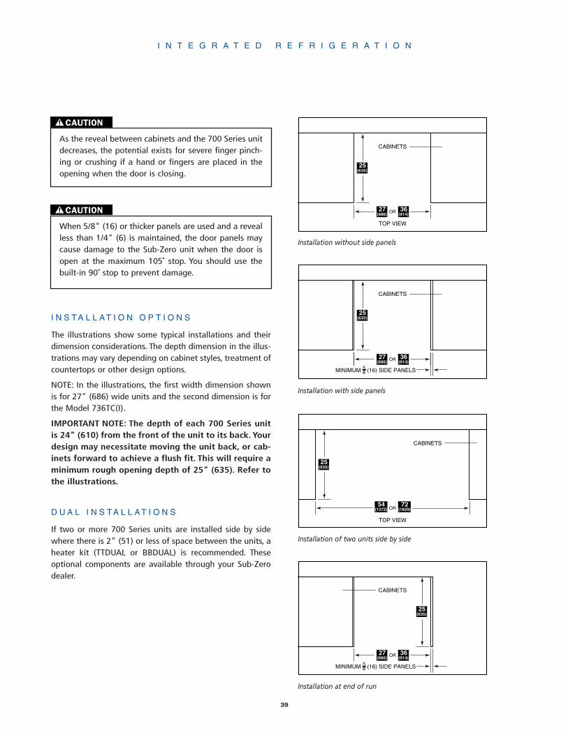
39
I N T E G R A T E D R E F R I G E R A T I O N
I N S T A L L A T I O N O P T I O N S
The illustrations show some typical installations and theirdimension considerations. The depth dimension in the illus-trations may vary depending on cabinet styles, treatment ofcountertops or other design options.
NOTE: In the illustrations, the first width dimension shownis for 27" (686) wide units and the second dimension is forthe Model 736TC(I).
IMPORTANT NOTE: The depth of each 700 Series unitis 24" (610) from the front of the unit to its back. Yourdesign may necessitate moving the unit back, or cab-inets forward to achieve a flush fit. This will require aminimum rough opening depth of 25" (635). Refer tothe illustrations.
D U A L I N S T A L L A T I O N S
If two or more 700 Series units are installed side by sidewhere there is 2" (51) or less of space between the units, aheater kit (TTDUAL or BBDUAL) is recommended. Theseoptional components are available through your Sub-Zerodealer.
TOP VIEW
CABINETS
25(635)
36(914)
27(686)
OR
Installation without side panels
MINIMUM (16) SIDE PANELS58
CABINETS
25(635)
36(914)
27(686)
OR
Installation with side panels
TOP VIEW
CABINETS
72(1829)
54(1372)
25(635)
OR
Installation of two units side by side
MINIMUM (16) SIDE PANELS58
CABINETS
25(635)
36(914)
27(686)
OR
Installation at end of run
CAUTION
As the reveal between cabinets and the 700 Series unitdecreases, the potential exists for severe finger pinch-ing or crushing if a hand or fingers are placed in theopening when the door is closing.
CAUTION
When 5/8" (16) or thicker panels are used and a revealless than 1/4" (6) is maintained, the door panels maycause damage to the Sub-Zero unit when the door isopen at the maximum 105˚ stop. You should use thebuilt-in 90˚ stop to prevent damage.
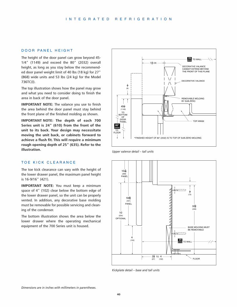
40
I N T E G R A T E D R E F R I G E R A T I O N
D O O R P A N E L H E I G H T
The height of the door panel can grow beyond 45-1/4" (1149) and exceed the 80" (2032) overallheight, as long as you stay below the recommend-ed door panel weight limit of 40 lbs (18 kg) for 27"(868) wide units and 53 lbs (24 kg) for the Model736TC(I).
The top illustration shows how the panel may growand what you need to consider doing to finish thearea in back of the door panel.
IMPORTANT NOTE: The valance you use to finishthe area behind the door panel must stay behindthe front plane of the finished molding as shown.
IMPORTANT NOTE: The depth of each 700Series unit is 24" (610) from the front of theunit to its back. Your design may necessitatemoving the unit back, or cabinets forward toachieve a flush fit. This will require a minimumrough opening depth of 25" (635). Refer to theillustration.
T O E K I C K C L E A R A N C E
The toe kick clearance can vary with the height ofthe lower drawer panel, the maximum panel heightis 16-9/16" (421).
IMPORTANT NOTE: You must keep a minimumspace of 4" (102) clear below the bottom edge ofthe lower drawer panel, so the unit can be properlyvented. In addition, any decorative base moldingmust be removable for possible servicing and clean-ing of the condenser.
The bottom illustration shows the area below thelower drawer where the operating mechanicalequipment of the 700 Series unit is housed.
4514
(1149)
TO BOTTOM
OF DOOR PANEL
TO FLOOR
14
(6)
112 (38)
TO WALL
DECORATIVE VALANCE
DECORATIVE VALANCECANNOT EXTEND BEYONDTHE FRONT OF THIS PLANE
REMOVABLE MOLDINGBY SUB-ZERO
TOP HINGE
25(635)
*FINISHED HEIGHT OF 80" (2032) IS TO TOP OF SUB-ZERO MOLDING
80*(2032)
10 916
(268)
16 916
(421)
PANEL
PANEL
10(254)
4(102)
OPTIONAL
258
(67)4
(102)TO
91116
(246)
12
(13)
FLOOR
TO WALL25
(635)
BASE MOLDING MUSTBE REMOVABLE
Upper valence detail – tall units
Kickplate detail – base and tall units
Dimensions are in inches with millimeters in parentheses.
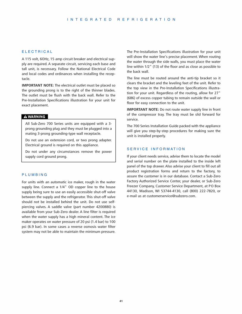
41
E L E C T R I C A L
A 115 volt, 6OHz, 15 amp circuit breaker and electrical sup-ply are required. A separate circuit, servicing each base andtall unit, is necessary. Follow the National Electrical Codeand local codes and ordinances when installing the recep-tacle.
IMPORTANT NOTE: The electrical outlet must be placed sothe grounding prong is to the right of the thinner blades.The outlet must be flush with the back wall. Refer to thePre-Installation Specifications illustration for your unit forexact placement.
P L U M B I N G
For units with an automatic ice maker, rough in the watersupply line. Connect a 1/4" OD copper line to the housesupply being sure to use an easily accessible shut-off valvebetween the supply and the refrigerator. This shut-off valveshould not be installed behind the unit. Do not use self-piercing valves. A saddle valve (part number 4200880) isavailable from your Sub-Zero dealer. A line filter is requiredwhen the water supply has a high mineral content. The icemaker operates on water pressure of 20 psi (1.4 bar) to 100psi (6.9 bar). In some cases a reverse osmosis water filtersystem may not be able to maintain the minimum pressure.
The Pre-Installation Specifications illustration for your unitwill show the water line's precise placement. When routingthe water through the side walls, you must place the waterline within 1/2" (13) of the floor and as close as possible tothe back wall.
The line must be routed around the anti-tip bracket so itclears the bracket and the leveling feet of the unit. Refer tothe top view in the Pre-Installation Specifications illustra-tion for your unit. Regardless of the routing, allow for 27"(686) of excess copper tubing to remain outside the wall orfloor for easy connection to the unit.
IMPORTANT NOTE: Do not route water supply line in frontof the compressor tray. The tray must be slid forward forservice.
The 700 Series Installation Guide packed with the appliancewill give you step-by-step procedures for making sure theunit is installed properly.
S E R V I C E I N F O R M A T I O N
If your client needs service, advise them to locate the modeland serial number on the plate installed to the inside leftpanel of the top drawer. Also advise your client to fill out allproduct registration forms and return to the factory, toassure the customer is in our database. Contact a Sub-ZeroFactory Authorized Service Center, your dealer, or Sub-ZeroFreezer Company, Customer Service Department, at PO Box44130, Madison, WI 53744-4130, call (800) 222-7820, ore-mail us at [email protected].
I N T E G R A T E D R E F R I G E R A T I O N
WARNING
All Sub-Zero 700 Series units are equipped with a 3-prong grounding plug and they must be plugged into amating 3-prong grounding-type wall receptacle.
Do not use an extension cord, or two prong adapter.Electrical ground is required on this appliance.
Do not under any circumstances remove the powersupply cord ground prong.

I N T E G R A T E D R E F R I G E R A T I O N
42
F R A M E D C A B I N E T R Y
IMPORTANT NOTE: The depth of each 700 Series unitis 24" (610) from the front of the unit to its back. Yourdesign may necessitate moving the unit back, or cab-inets forward to achieve a flush fit.
18
34
MIN.(3)
PANEL
SIDE MOLDING ANDINSTALLATION HARDWAREPROVIDED BY SUB-ZERO
LINE OF INTERFERENCEAT MAXIMUM DOOR OPENING
MOUNTING BRACKET SCREW
(19)
FLUSH FURNITURE FINISH
LINE OF INTERFERENCE
TO BACKOF UNIT
24(610)
SUB-ZERO DOOR
2578 (657) APPLIANCE DOOR WIDTH347
8 (886) FOR MODEL 736TC(I)
REVEAL
24(610)
LINE OF INTERFERENCE
SUB-ZERO DOOR
TO BACK OF UNIT
Door closed – full scale (top view)
105˚ maximum door opening – 1/4 scale (top view)
Dimensions are in inches with millimeters in parentheses.

I N T E G R A T E D R E F R I G E R A T I O N
43
18 MIN.(3)
REVEAL
34 PANEL
LINE OF INTERFERENCEAT MAXIMUM DOOR OPENING
MOUNTING BRACKET SCREW
(19)
TO BACK OF UNIT
24(610)
SIDE MOLDING ANDINSTALLATION HARDWAREPROVIDED BY SUB-ZERO
LINE OF INTERFERENCE
SUB-ZERO DOOR
2578 (657) APPLIANCE DOOR WIDTH347
8 (886) FOR MODEL 736TC(I)
TO WALL
24(610)
LINE OF INTERFERENCE
SUB-ZERO DOOR
3/4" (19) DOOR PANEL
SIDE PANELCOUNTERTOP
105˚ maximum door opening – 1/4 scale (top view)Adjacent side panel and countertop application
Door closed – full scale (top view)
Dimensions are in inches with millimeters in parentheses.
F R A M E L E S S C A B I N E T R Y
IMPORTANT NOTE: The depth of each 700 Series unitis 24" (610) from the front of the unit to its back. Yourdesign may necessitate moving the unit back, or cab-inets forward to achieve a flush fit.

44
C R E A T I N G S O L U T I O N S F O R H O M E R E F R I G E R A T I O N
Sub-Zero's innovative addition to its complete line of residential refrigeration iswine storage equipment, the 400 Series. But it is more than just wine storage inthe conventional sense. It is wine storage as only Sub-Zero could make it. The ulti-mate in beauty, engineering, attention to detail and smart thinking will ensurethis series is an instant success.
There are, obviously, right and wrong ways to store wine. You will quickly see thatSub-Zero is committed to the right way. From the exterior and the smooth linesof the free-standing Model 424FS classic stainless steel to the ability to use woodon the built-in models, each unit is beautiful.
With the exception of the free-standing Model 424FS, each model is available inthree stainless steel finishes and will have the capability of having wood panelsapplied to the doors and with the Model 427R, you can also apply the wood tothe drawers.
There are some subtle differences and it is important to understand them.
• The free-standing Model 424FS does not require any panels or surroundingcabinetry, it comes with classic stainless steel exterior.
• All units will be shipped with glass doors as standard equipment. The glassdoors allow one to see the wine that is being stored. If you would like a tradi-tional Sub-Zero look, there is the optional solid doors, which will be treated asspecial orders and must be ordered 90 days before you expect delivery. Solid doorpanels must not be installed on glass door units.
• Stainless steel units will be shipped with tubular stainless steel handles, whilethe overlay units will come with no handle hardware. Optional stainless steelpanels and handles for Models 427 and 427R are offered in the classic, platinumand carbon stainless steel finishes and are ordered and shipped as sales acces-sories. The stainless steel Models 424 and 430 must be ordered in one of threestainless steel finishes of classic, platinum and carbon.
• Optional handles are available for all models except the framed and stainlesssteel Model 430. Contact your Sub-Zero dealer for details. The framed Model 430will come with an extruded handle identical in design to our 600 Series look.
• Standard grille assemblies for the Model 430 will be provided in 1" (25) incre-ments from 10" (254) to 15" (381). The standard height will be 11" (279). Theframed unit will have a louvered grille, the stainless steel unit will feature aheavy-duty grille and the overlay model will have the panel grille which acceptsdecorative panel inserts.
W I N E S T O R A G E
4 0 0S E R I E S
Dimensions in parentheses are in millimeters unless otherwise specified.

45
As with all Sub-Zero units, the 400 Series is manufactured to the exacting quali-ty standards which has made us the leader of the refrigeration industry. Becausethe 400 Series comes with everything you need to ensure your customer's wineis stored properly and safely, there are only a few options. For information regard-ing specific 400 Series models, refer to the illustrations and charts in this section.
400 Series Models common features:
• Two distinct wine storage temperature zones
• Electronic control panel with microprocessor
• Ideal humidity environment
• Roller-glide shelves
• Storage for standard bottles, half-bottles and magnums
• Rust-proof wire shelves with cherry wood facing
• Illuminated display shelf (except Models 424 and 424FS)
• Discreet interior lighting
• Service indicator and home security tie-in
• UV resistant glass protection
• Divider gasket to ensure separate temperatures
• Front venting
The illustrations below represent the full line of Sub-Zero 400 Series models. TheModel 424 can be ordered as a built-in or free-standing unit. If you order theModel 424FS, which is a free-standing unit, it comes with classic stainless steelexterior.
Comprehensive installation instructions are shipped with each unit. Refer tothose instructions in preparing and installing all Sub-Zero products, call Sub-ZeroFreezer Company at (800) 222-7820 or check our website at www.subzero.com.
Model 424UndercounterWine Storage
Model 427Wine Storage
Model 427RWine Storage
with RefrigerationDrawers
Model 430Wine Storage
Model 424FSFree-StandingWine Storage
W I N E S T O R A G E
4 0 0S E R I E S
27"(686)
27"(686)
30"(762)
34"(864)
237/8"(606)
241/4"(616)
343/16"(868)
80"(2032)
80"(2032)
84"(2134)

46
W I N E S T O R A G E
Model 424
MODEL OPTIONS
424/O Overlay Design
424/S Classic Stainless
424/P Platinum Stainless
424/B Carbon Stainless
Full-View Glass Door (standard)
High Altitude Glass Door
Solid Door
SPECIFICATIONS
Undercounter Wine Storage
237/8"W x 34"H x 24"D(606 x 864 x 610)
Storage Capacity46 (750 ml) Bottles
Door Swing Clearance253/8" (645)
Specify LH or RH Door Swing
Shipping Weight190 lbs (86 kg) Glass Door195 lbs (88 kg) Glass Door/Stainless Steel185 lbs (84 kg) Solid Door
FEATURES
2 Temperature Zones
2 Upper Compartment Shelves
3 Lower Compartment Shelves
8 (750 ml) Bottles perStandard Shelf
Model 427
MODEL OPTIONS
Full-View Glass Door (standard)
High Altitude Glass Door
Solid Door
SPECIFICATIONS
Wine Storage
27"W x 80"H x 24"D(686 x 2032 x 610)
Storage Capacity132 (750 ml) Bottles
Minimum Height Required791/2" (2019)
Door Swing Clearance251/2" (648)
Specify LH or RH Door Swing
Shipping Weight395 lbs (179 kg) Glass Door386 lbs (175 kg) Solid Door
PANEL OPTIONS
Integrated
Classic, Platinum or CarbonStainless Steel Finish(includes handle)
FEATURES
2 Temperature Zones
5 Upper Compartment Shelves
9 Lower Compartment Shelves
Display Shelf
9 (750 ml) Bottles perStandard Shelf
6 (750 ml) Bottles perDisplay Shelf
▼58 42▲ MODEL 427WINE STORAGE
▼58 42▲
MODEL 424
WINE STORAGE
Model 424 Model 427
Model 424FS
MODEL OPTIONS
Full-View Glass Door (standard)
High Altitude Glass Door
Solid Door
SPECIFICATIONS
Free-StandingUndercounter Wine Storage
241/4"W x 343/16"H x 245/8"D(616 x 868 x 625)
Storage Capacity46 (750 ml) Bottles
Door Swing Clearance253/8" (645)
Specify LH or RH Door Swing
Shipping Weight220 lbs (100 kg)
FEATURES
Classic Stainless Steel Exteriorand Door Frame
2 Temperature Zones
2 Upper Compartment Shelves
3 Lower Compartment Shelves
8 (750 ml) Bottles perStandard Shelf
▼58 42▲
MODEL 424
WINE STORAGE
Model 424FS
4 0 0S E R I E S

47
W I N E S T O R A G E
Model 430
MODEL OPTIONS
430/F Framed Design
430/O Overlay Design
430/S Classic Stainless
430/P Platinum Stainless
430/B Carbon Stainless
Full-View Glass Door (standard)
High Altitude Glass Door
Solid Door
SPECIFICATIONS
Wine Storage
30"W x 84"H x 24"D(762 x 2032 x 610)
Storage Capacity147 (750 ml) Bottles
Minimum Height Required827/8" (2105)
Door Swing Clearance301/8" (765)
Specify LH or RH Door Swing
Shipping Weight435 lbs (197 kg) Glass Door445 lbs (202 kg) Glass Door/Stainless Steel412 lbs (187 kg) Solid Door
FEATURES
2 Temperature Zones
5 Upper Compartment Shelves
9 Lower Compartment Shelves
Display Shelf
10 (750 ml) Bottles perStandard Shelf
7 (750 ml) Bottles perDisplay Shelf
▼58 42▲ MODEL430WINE STORAGE
Model 430
Model 427R
MODEL OPTIONS
Full-View Glass Door (standard)
High Altitude Glass Door
Solid Door
SPECIFICATIONS
Wine Storage with Refrigeration Drawers
27"W x 80"H x 24"D(686 x 2032 x 610)
Storage Capacity78 (750 ml) Bottles
Minimum Height Required791/2" (2019)
Refrigerator Capacity5.3 cu ft (150 L)
Door Swing Clearance251/2" (648)
Specify LH or RH Door Swing
Shipping Weight410 lbs (186 kg) Glass Door406 lbs (184 kg) Solid Door
PANEL OPTIONS
Integrated
Classic, Platinum or CarbonStainless Steel Finish(includes handles)
FEATURES
3 Temperature Zones
6 Upper Compartment Shelves
2 Lower Compartment Shelves
Display Shelf
9 (750 ml) Bottles perStandard Shelf
6 (750 ml) Bottles perDisplay Shelf
2 Refrigeration Drawers
▼58 42▲ MODEL427RWINE STORAGE
Model 427R
IMPORTANT NOTE: Orders forsolid and high altitude glassdoors will be regarded as spe-cial orders. You must allow for90 days from the time of orderuntil you can expect delivery.High altitude glass doors arefor installations at or over5,000' (1524 m) in elevation.
Optional stainless steel panelsfor Models 427 and 427R, avail-able for glass door or solid doorunits, are ordered and shippedas sales accessories and includetubular stainless steel handles.
Optional panel finishes –(S) Classic stainless steel(P) Platinum stainless steel(B) Carbon stainless steel
Dimensions in parentheses arein millimeters unless otherwisespecified.
48
W I N E S T O R A G E
F E A T U R E S A N D O P T I O N S
When looking for wine storage, you no longer have to thinkonly about an undercounter application. Sub-Zero offersyou complete flexibility from the perspective of designapplications and storage capabilities.
• Model 424 comes in the overlay and stainless steel doorpanel configurations. Model 424FS (free-standing) is identi-cal to the Model 424, but with classic stainless steel exteri-or and designed to be attractive in a stand alone setting.
• Models 427 and 427R are offered as integrated or stain-less steel. Optional stainless steel panels and handles forModels 427 and 427R are offered in the classic, platinumand carbon stainless steel finishes and are ordered andshipped as sales accessories.
• Model 430 comes in the framed, overlay and stainlesssteel options.The stainless steel Model 430 must be orderedin one of the three stainless steel finishes of classic, plat-inum and carbon.
Dual Refrigeration System. In a similar fashion to our600 Series, each 400 Series model has dual refrigeration soyour client will have specific, individual temperature controlof the two wine compartments.
Electronic Controls. Microprocessor offers touch pad con-trols that are easy to understand and set the temperaturesaccurately.
Display Shelf. This beautiful shelf offers your clients theopportunity to display those prize bottles or magnums ofwine in their collection. It is illuminated with discreet light-ing mounted in the control panel. (Not available with Mod-els 424 and 424FS.)
Storage Shelves. The sturdy, rustproof wire shelves caneasily accommodate standard 750 ml bottles, half-bottles,as well as magnums. All the shelves are finished off with anatural cherry wood facing. In addition, all shelves willenable you to be sure the wine is stored properly and thatthe corks are in contact with the bottles' contents.
Roller Assembly. All shelves have a roller assembly, whichenables you to have a three-quarter extension for easyaccess to all bottles of stored wine.
Service Alert. An indicator light will let you know if serv-ice may be necessary; in addition, you have the option ofhooking the equipment up to your home security system.
Discreet Lighting. Our soft low wattage lighting is inde-pendent of door opening.
Correct Temperatures. The temperature range of eachwine compartment is 38˚F (3˚C) to 65˚F (18˚C) and your settemperature is digitally displayed in the control panel.
Humidity. Proper humidity is maintained throughout theentire unit.
UV Protection. The tinted glass minimizes the amount ofultraviolet light entering the unit.
Lock. A lock will be offered as an option for all 400 Seriesmodels. The lock is offered as a sales accessory and shouldbe ordered through your Sub-Zero dealer. Special planningis necessary when ordering locks for Models 427 and 427R,see page 54 for details.
Solid Doors. If you would like to order a unit without glass,you have that option. This will be treated as a special orderand must be ordered 90 days before you expect delivery.
High Altitude Glass. For installations above 5,000'(1524 m) in elevation, we offer the high altitude glass as aspecial order.
Built-in Look. Sub-Zero offers you a host of design alter-natives to choose from when choosing the look you want.Wood or stainless steel, framed, overlay or integrated.
Tight Seal. Magnetic gaskets around the doors give extratight seals.
Kickplate. The solid, adjustable kickplate gives a true built-in look, and conforms to American Institute of Architectsstandards.
Front Venting. All Sub-Zero wine storage units aredesigned for mechanical system air flow at the front of theappliance. Decorative panels must not cover louvered sur-faces or prevent removal of louvered components.
Sub-Zero Warranty. Like all Sub-Zero units, the 400 Seriesis covered by the Sub-Zero Freezer Company Products Lim-ited Warranty, exclusions apply. See page 70 for details.
Dimensions in parentheses are in millimeters unless otherwise specified.

49
W I N E S T O R A G E
AROUGH
OPENINGWIDTH
25"(635)
ROUGHOPENING
DEPTH
BROUGH
OPENINGHEIGHT
LOCATEELECTRICAL
WITHINSHADED AREA
ANTI-TIPBRACKET
TOP VIEW
E
151/2"(394)
41/2"(114) 21/2"
(64)
Pre-Installation Specifications – Models 427 and 427R
751/2"(1918)
7"(179)
6"(152)
AROUGH
OPENINGWIDTH
24"(610)
ROUGHOPENING
DEPTH
E
LOCATE ELECTRICALFOR MODEL 430
WITHIN TOPSHADED AREA
LOCATE ELECTRICALFOR MODEL 424WITHIN BOTTOMSHADED AREA
TOP VIEW
E
151/2"(394)
41/2"(114) 21/2"
(64)
BROUGH
OPENINGHEIGHT
Pre-Installation Specifications – Models 424 and 430
Model 424 427 427R 430
Finished Rough Opening Width (A) 24"(610) 27"(686) 27"(686) 291/2"(749)
Finished Rough Opening Height (B) 341/2"(876) 80"(2032) 80"(2032) 833/4"(2127)
Minimum Height Required 341/4"(870) 791/2"(2019) 791/2"(2019) 827/8"(2105)
NOTE: The free-standing Model 424FS requires no surrounding cabinetry.
P R E - I N S T A L L A T I O N S P E C I F I C A T I O N S
IMPORTANT NOTE: The depth of Models 427 and 427Ris 24" (610) from the front of the unit to its back. Yourdesign may necessitate moving the unit back, or cab-inets forward to achieve a flush fit. This will require aminimum rough opening depth of 25" (635). Refer tothe illustration.

50
W I N E S T O R A G E
P L A N N I N G I N F O R M A T I O N
Review the installation requirements for your particular unitin the Pre-Installation Specifications chart and illustrationson the previous page. They cover all the details you need toknow about space allocation and placement of electrical,whether the units are framed, overlay, stainless steel orintegrated.
All 400 Series units must be installed so that the door canopen a minimum of 90˚ or you will have problems pullingthe wine shelves out. Refer to the door clearance and doorswing information in the following illustrations and chart.
C90˚
D
C
F
E
Minimum Door Clearance at 90˚ and at Maximum Door Swing –Models 424, 424FS, 427, 427R and 430
Model 424 424FS 427 427R 430
Minimum Door Clearance (C) 253/8"(645) 253/8"(645) 251/2"(648) 251/2"(648) 301/8"(765)
Minimum Clearance at 90˚ Door Swing (D) 26"(660) 26"(660) 28"(711) 28"(711) 33"(838)
Maximum Door Swing (E) 145˚ 145˚ 105˚ 105˚ 130˚
Minimum Clearance at Maximum Door Swing (F) 44"(1118) 44"(1118) 35"(889) 35"(889) 50"(1270)
NOTE: Door swing clearances are based on stainless steel door and handle dimensions.
• For corner installations, you need allow for a minimum 3"(76) filler so the door can open to 90˚. If you are using somelarger handle hardware, you will also need to take that intoaccount.
• For a maximum 90˚ door opening, use the door stop builtinto the hinge system of Models 427 and 427R. An option-al 90˚ door stop kit for Model 430 is available from yourSub-Zero dealer.
• If installing a wine unit next to an existing Sub-Zero unit,you may have to allow for a filler strip.
• If installing a wine unit next to an existing Sub-Zero unit,with 2" (51) or less in between units, an optional heater kit(TTDUAL or BBDUAL) will need to be installed to preventmoisture from forming in between units. These optionalcomponents are available through your Sub-Zero dealer.
• If you are connecting the unit to your home securitysystem, you must allow a minimum of 36" (914) of the sys-tem's wiring to be routed in the electrical area designatedfor your respective model.
IMPORTANT NOTE: The anti-tip bracket must be installedto prevent the unit from tipping forward.
Refer to the full-scale illustrations at the end of this sectionfor specifics on door openings and other specifications.
Installation procedures are covered in detail in the Sub-Zero400 Series Installation Guide accompanying the unit.
Dimensions in parentheses are in millimeters unless otherwise specified.

I N T E G R A T I N G C A B I N E T R Y
Unless you are installing a stainless steel unit, you will needto provide a complete door panel in the instance of a soliddoor unit, or a frame for the glass door application, wherewine will be seen from the outside. If you order a stainlesssteel unit, the Models 424, 424FS and 430 will be shippedwith their panels and hardware installed and you will mere-ly install the Sub-Zero. However, for the Models 427 and427R, you will have to have the stainless steel panels andhandles installed.
400 Series solid door models are available as a specialorder. You must allow 90 days from the time of order untilyou can expect delivery.
M O D E L 4 2 4 F S – F R E E - S T A N D I N G
The free-standing Model 424FS does not require any panelsor surrounding cabinetry. It has a beautiful classic stainlesssteel exterior, door frame and handle. Refer to the OverallDimensions illustration below for the Model 424FS.
M O D E L 4 2 4 – O V E R L A Y P A N E L S
The overlay panels applied to the Model 424 should not beconfused with the 600 Series overlay panel application. TheModel 424 panel will consist of only a frame and would beeither the 5/8" (16) or 3/4" (19) panel you may be using. Itis affixed directly to the door itself with screws through aseries of pre-drilled holes in the perimeter of the door itself.You do not need any backer or spacer panel.
Refer to the Overall Dimensions and Cabinetry Dimensionsillustrations for Model 424 to give you a better idea of theexact space our unit needs and how the panel fits in rela-tionship with the unit. The panel specifications chart willprovide panel sizing information.
The glass door opening of the standard Model 424 isdesigned to be exposed to room air circulation. Decorativeoverlays on the glass should be kept to a minimum. Also,rails and stiles can be increased in size but should notexceed cabinet manufacturers standard width. They cannotexceed overall door panel dimensions specified, as theywould interfere with the operation of the door. The backsides of rails and stiles that will be visible through the glassdoor will need to be finished. Also, the inside edges of theframes must be finished to match the front surface.
Please note in the overall dimensions illustrations the loca-tion of pre-drilled holes for optional handle hardware. Referto page 57 for specifics about installing handle hardware onthis overlay application.
* INCH (13) ± ADJUSTMENT IN LEVELING LEGS
MODEL 424 OVERALL DIMENSIONS
12
FRONT VIEW SIDE VIEW
(CABINET DIMENSION)
4(102)
34
(273)10
CENTEREDVERTICALLY
DOOR FRAME(597)1223
30(767)
DOORFRAME
*34(864)
(587)1823
316
23 78
(606)
* INCH (13) ± ADJUSTMENT IN LEVELING LEGS
FRONT VIEW SIDE VIEW
(CABINET DIMENSION)
TOE KICK
24 14
(616)
4(102)
(625)5824
MODEL 424FS OVERALL DIMENSIONS
12
*34 316
(868)
W I N E S T O R A G E
51
CAUTION
A solid panel must not be installed on a glass door unit,as this may cause moisture to form behind the panel.
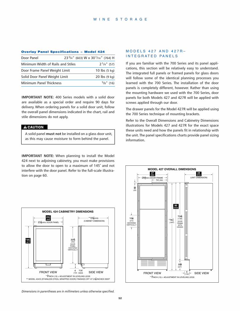
* INCH (13) ± ADJUSTMENT IN LEVELING LEGS
** MODEL 424/S (STAINLESS STEEL WRAPPED DOOR) FINISHES OFF AT 23 INCHES DEEP
MODEL 424 CABINETRY DIMENSIONS
12
FRONT VIEW SIDE VIEW
(CABINET DIMENSION)DOOR PANEL(603)
3423
30(764)
DOORPANEL
CENTEREDVERTICALLY
*3412
(877)
(606)78**23
116
TOEKICK
23 78
(606)
4(102)
78
52
IMPORTANT NOTE: 400 Series models with a solid doorare available as a special order and require 90 days fordelivery. When ordering panels for a solid door unit, followthe overall panel dimensions indicated in the chart, rail andstile dimensions do not apply.
IMPORTANT NOTE: When planning to install the Model424 next to adjoining cabinetry, you must make provisionsto allow the door to open to a maximum of 145˚ and notinterfere with the door panel. Refer to the full-scale illustra-tion on page 60.
Overlay Panel Specifications – Model 424
Door Panel 233/4" (603) W x 301/16" (764) H
Minimum Width of Rails and Stiles 21/4" (57)
Door Frame Panel Weight Limit 10 lbs (5 kg)
Solid Door Panel Weight Limit 20 lbs (9 kg)
Minimum Panel Thickness 5/8" (16)
M O D E L S 4 2 7 A N D 4 2 7 R –I N T E G R A T E D P A N E L S
If you are familiar with the 700 Series and its panel appli-cations, this section will be relatively easy to understand.The integrated full panels or framed panels for glass doorswill follow some of the identical planning processes youlearned with the 700 Series. The installation of the doorpanels is completely different, however. Rather than usingthe mounting hardware we used with the 700 Series, doorpanels for both Models 427 and 427R will be applied withscrews applied through our door.
The drawer panels for the Model 427R will be applied usingthe 700 Series technique of mounting brackets.
Refer to the Overall Dimensions and Cabinetry Dimensionsillustrations for Models 427 and 427R for the exact spacethese units need and how the panels fit in relationship withthe unit. The panel specifications charts provide panel sizinginformation.
* INCH (13) ± ADJUSTMENT IN LEVELING LEGS12
MODEL 427 OVERALL DIMENSIONS
14
FRONT VIEW SIDE VIEW
(356)
(UNIT DIMENSION)
1316(20)
*7858
(1997)
81516
(227)
4(102)
27(686)
24(610)
34
(273)10
CENTEREDVERTICALLY
DOOR FRAME(664)1826
70 716
(1789)
DOORFRAMEWITH
HINGES
80(2032)
W I N E S T O R A G E
Dimensions in parentheses are in millimeters unless otherwise specified.
CAUTION
A solid panel must not be installed on a glass door unit,as this may cause moisture to form behind the panel.

53
IMPORTANT NOTE: The depth of Models 427 and 427Ris 24" (610) from the front of the unit to its back. YouMUST allow for the thickness of the panel you areapplying when planning for the finished rough open-ing depth if you want the front panel to be flush withsurrounding cabinetry. You may have to move the unitback into drywall or bring the cabinets forward. Referto pages 36-40 of the 700 Series section.
IMPORTANT NOTE: The glass door opening of the standardModels 427 and 427R is designed to be exposed to room aircirculation. Decorative overlays on the glass should be keptto a minimum. While the cabinet front stiles are a minimumof 2-1/4" (57) for both Models 427 and 427R, the top andbottom rails are different. Rails and stiles can be increasedin size but should not exceed cabinet manufacturers stan-dard width. They cannot exceed overall door panel dimen-sions specified, as they would interfere with the operationof the door. The back sides of rails and stiles that will be vis-ible through the glass door will need to be finished. Also,the inside edges of the frames must be finished to matchthe front surface.
* INCH (13) ± ADJUSTMENT IN LEVELING LEGS
MODEL 427R OVERALL DIMENSIONS
14
DRAWER FRONT
FRONT VIEW SIDE VIEW
(356)
2038
(517)
12
(13)
1014
(260)
1314
(337)
38
(9)
(UNIT DIMENSION)
1316(20)
*7858
(1997)
9 34
(248)
4(102)
27(686)
24(610)
34
(273)10
CENTEREDVERTICALLY
(650)9
1625
DOOR FRAME(664)1826
*3412
(877)
4478
(1139)
DOORFRAMEWITH
HINGES
12
80(2032)
* INCH (13) ± ADJUSTMENT IN LEVELING LEGS
MODEL 427 CABINETRY DIMENSIONS
12
FRONT VIEW SIDE VIEW
(UNIT DIMENSION)
80(2032)
27(686)
24(610)
DOOR PANEL(679)3426
79 34
(2026)
TRIMMEDDOOR
FINISHED OPENING
7534
(1924)
4(102)
TOE KICK
4(102)
TOE KICK
FINISHED OPENING
DOORPANEL
IMPORTANT NOTE: The dimensions of these panels andstiles are assuming the models finish off at 80" (2032) inheight overall and have a 4" (102) toe kick for the Model427. If you finish off at 84" (2134) for instances, you mustadd 4" (102) additional to the overall height of the paneland remember to add 4" (102) to the top rail. Likewise, ifyou allow for a 6" (152) toe kick for the Model 427, youmust subtract 2" (51) from the bottom rail.
Door panels for Models 427 and 427R can grow beyond the80" (2032) height to accommodate any size of door as longas you stay below door panel weight limit of 20 lbs (9 kg)for glass door units and 40 lbs (18 kg) for solid door units.Refer to the specifications under Door Panel Height on page40 of the 700 Series section.
IMPORTANT NOTE: The toe kick area on the Model 427cannot be larger than 6" (152), and no larger than 9" (229)for the 427R.
Please note in the overall dimensions illustrations the loca-tion of pre-drilled holes for optional handle hardware. Referto page 57 for specifics about installing handle hardware onthis overlay application.
W I N E S T O R A G E

IMPORTANT NOTE: If you are installing Sub-Zero's option-al lock kit on a Model 427 or 427R, you may have to orderdoor panels that exceed the 80" (2032) finishing height.Consult the lock installation instructions and see if yourpanels will allow for an adequate installation.
IMPORTANT NOTE: In the following chart for Model 427R,the bottom drawer panel height is based on a 4" (102) toekick. If you want to show a 6" (152) toe kick, you must sub-tract 2" (51) from the bottom drawer panel height.
M O D E L 4 3 0 –F R A M E D A N D O V E R L A Y P A N E L S
The framed and overlay treatments of panels for the Model430 are identical to the Model 611 in width and Model 632in height, you will need to be aware of some of flexibilityand limitations these issues give you.
Refer to the Overall Dimensions and Cabinetry Dimensionsillustrations for Model 430 for the exact space our unitneeds and how the panel fits in relationship with the unit.The panel specifications charts provide panel sizing forframed and overlay applications.
IMPORTANT NOTE: 400 Series models with a solid doorare available as a special order and require 90 days fordelivery. When ordering panels for a solid door unit, followthe overall panel dimensions indicated in the chart, rail andstile dimensions do not apply.
* INCH (13) ± ADJUSTMENT IN LEVELING LEGS
MODEL 427R CABINETRY DIMENSIONS
12
DRAWER PANEL
FRONT VIEW SIDE VIEW
14(6)
16 916
(421)
13 716
(341)
14
(6)
(UNIT DIMENSION)
*3412
(877)
80(2032)
27(686)
24(610)
(679)3426
DOOR PANEL(679)3426
79 34
(2026)
FINISHED OPENING
4514
(1149)
4(102)
TOE KICK
4(102)
TOE KICK
FINISHED OPENING
TRIMMEDDOOR
Integrated Panel Specifications – Model 427R
Door Panel 263/4" (679) W x 451/4" (1149) H
Minimum Width of Top Rail 35/8" (92)
Minimum Width of Bottom Rail 3" (76)
Minimum Width of Stiles 21/4" (57)
Door Frame Panel Weight Limit 20 lbs (9 kg)
Solid Door Panel Weight Limit 40 lbs (18 kg)
Top Drawer Panel 263/4" (679) W x 137/16" (341) H
Bottom Drawer Panel 263/4" (679) W x 169/16" (421) H
Drawer Panel Weight Limit 12 lbs (5 kg) each
Minimum Panel Thickness 5/8" (16)
Integrated Panel Specifications – Model 427
Door Panel 263/4" (679) W x 753/4" (1924) H
Minimum Width of Top Rail 35/8" (92)
Width of Bottom Rail 8" (203)
Minimum Width of Stiles 21/4" (57)
Door Frame Panel Weight Limit 20 lbs (9 kg)
Solid Door Panel Weight Limit 40 lbs (18 kg)
Minimum Panel Thickness 5/8" (16)
W I N E S T O R A G E
54
CAUTION
A solid panel must not be installed on a glass door unit,as this may cause moisture to form behind the panel.
Dimensions in parentheses are in millimeters unless otherwise specified.
IMPORTANT NOTE: 400 Series models with a solid doorare available as a special order and require 90 days fordelivery. When ordering panels for a solid door unit, followthe overall panel dimensions indicated in the chart, rail andstile dimensions do not apply.

M O D E L 4 3 0 – F R A M E D P A N E L S
Unlike the Model 611, you cannot use a 1/4" (6) panel tocover the glass door. It is fine when applying a panel to thesolid door, but in either instance, you should consider usingraised panels with a minimum 5/8" (16) thickness.
When using a raised, framed panel, you must allow for theedge to be routed 1/4" (6) around the panel to ensure aproper fit. See illustration 1.
With the framed Model 430, you will receive an extrudedhandle identical in appearance to the 600 Series units. How-ever, it will be an extended handle and will enable you touse raised panels without providing finger clearance toopen the door.
* INCH (13) ± ADJUSTMENT IN LEVELING LEGS
MODEL 430 CABINETRY DIMENSIONS
12
FRONT VIEW SIDE VIEW
84(2134)
4 116
(103)
68(1727)
CENTEREDVERTICALLY
DOORPANEL
TOE KICK
DOOR FRAME(722)7
1628
30(762)
* INCH (13) ± ADJUSTMENT IN LEVELING LEGS
MODEL 430 OVERALL DIMENSIONS
12
FRONT VIEW SIDE VIEW
84(2134)
418
(105)
34
(273)10
CE
NT
ER
ED
VE
RT
ICA
LLY
DOOR FRAME(719)5
1628
6778
(1724)
(606)7823
DOORFRAME
TOE KICK
30(762)
Rout to 1/4″ (6) thickness
Trim reveal 1/4″ (6) min.
Glass
21/4″ (57) Rail orStile
DoorFrame
5/8″(16)
Framed Panel Specifications – Model 430
Framed Door Panel 281/8" (714) W x 6711/16" (1719) H
Minimum Width of Rails and Stiles 21/4" (57)
Door Frame Panel Weight Limit 25 lbs (11 kg)
Solid Door Panel Weight Limit 50 lbs (23 kg)
Minimum Panel Thickness 5/8" (16)
W I N E S T O R A G E
Illus. 1
55
CAUTION
A solid panel must not be installed on a glass door unit,as this may cause moisture to form behind the panel.

M O D E L 4 3 0 – O V E R L A Y P A N E L S
Your overlay unit will be shipped without handle hardwareand with an 11" (279) overlay panel grille as standardequipment. You will need to order a panel for the grille andhardware to complement your surrounding cabinetry.
While the overlay panel design offers you a more seamlessappearance, you need to be aware of adjacent cabinetsand/or countertops when the door is opened. Refer to thefull-scale illustrations at the end of the 600 Series section.
To achieve the overlay look, you need three different panels–the decorative overlay panel, a 0.10" (3) spacer panel anda 1/4" (6) backer panel. Depending on your cabinet manu-facturer, this could be one panel routed for different dimen-sions or more likely, three different panels. Refer to theOverlay Panel Specifications charts for complete details onthe overlay sizing. In addition, illustrations 2 and 3 will giveyou a better idea of the panel construction and how it inter-acts with our frame.
The glass door opening of the standard Model 430 isdesigned to be exposed to room air circulation. Decorativeoverlays on the glass should be kept to a minimum. Also,rails and stiles can be increased in size but should notexceed cabinet manufacturers standard width. They cannotexceed overall door panel dimensions specified, as theywould interfere with the operation of the door.
The back sides of rails and stiles that will be visible throughthe glass door will need to be finished. Also, the insideedges of the frames must be finished to match the front sur-face.
As with the Sub-Zero 600 Series equipment, you have theflexibility of ordering larger or smaller panel grilles foreither the framed or overlay applications. For specific panelsizing on these optional grilles for either the framed or over-lay applications of the Model 430, please refer to pages 15or 18 of the 600 Series section of this Design Guide.
In addition, side panel information for a Model 430 is avail-able on page 19 of this Design Guide.
Minimum
0.10″(3)
Overlay Panel
1/4" (6) Backer Panel
0.10″ (3) Spacer Panel
Door/Grille Trim5/32"(4)
1/16"(2)
5/16"
Door Frame
21/4" (57) Rail/Stile
Glass
DOOR FRAME CROSS SECTION
(8)
Backer Panel
1/4"(6)
5/8"min.
0.10"
Spacer Panel
Overlay Panel
(16)
(3)
Overlay Panel Specifications – Model 430
Overlay Door Panel 287/16" (722) W x 68" (1727) H
Spacer Panel 271/2" (699) W x 671/16" (1073) H
Backer Panel 281/8" (714) W x 6711/16" (1719) H
Minimum Width of Rails and Stiles 21/4" (57)
Door Panel Weight Limit 25 lbs (11 kg)
Solid Door Panel Weight Limit 50 lbs (23 kg)
Minimum Panel Thickness 5/8" (16)
Grille Panel Specifications – Model 430
Overlay Grille Panel 287/16" (722) W x 101/4" (260) H
Spacer Panel 271/2" (699) W x 95/16" (236) H
Backer Panel 281/8" (714) W x 915/16" (252) H
Grille Panel Weight Limit 15 lbs (7 kg)
Minimum Panel Thickness 5/8" (16)
W I N E S T O R A G E
Illus. 2 Illus. 3
56
Dimensions in parentheses are in millimeters unless otherwise specified.
W O O D F A C I N G – W I N E S H E L V E S
Sub-Zero has provided a natural cherry wood facing to eachof its wine shelves in each model. If, however, you wouldlike to replace these strips with wood more complementaryto your design and surrounding cabinetry, you can.
The Wine Shelf Wood Facing Dimensions illustration at theend of this section, can be used as a full-scale template. Youmust follow the layout of this format to accommodate theshelves properly. To remove the cherry strips, take theshelves out and merely remove the screws. Reverse the pro-cedure to affix the new wood.
If you choose to stain or seal the wood facing, be awarethat some of these substances are hazardous and will dam-age stored wine.
H A R D W A R E C O N S I D E R A T I O N S
With the Model 424 (overlay), Models 427 and 427R (inte-grated) and Model 430 (overlay), you must supply your ownhandle hardware. It is recommended you use our optionalhandles and use the pre-drilled holes supplied to locate thehandles within the frame of our unit. This will allow you toprovide the best possible handle alignment and not takeaway from the strength of the stile in this area after the unitis used a number of times. We recommend using a pull han-dle and not a pull knob.
If you elect to place different hardware on these units, weencourage you to fasten the hardware by passing throughour door and attach the hardware through the Sub-Zerodoor's frame.
Optional stainless steel handles are available in a variety ofdiameters and lengths, as well as handles to match thecolor and style of Wolf ovens. Contact your Sub-Zero dealerfor specifics.
E L E C T R I C A L
A 115 volt, 60 Hz, 15 amp fused electrical supply isrequired. It is recommended that a separate circuit, servingonly this appliance, be provided.
All Sub-Zero 400 Series units are equipped with a powersupply cord with a 3-prong grounding plug and it must beplugged into a mating 3-prong grounding type wall recep-tacle. Follow the National Electrical Code and local codesand ordinances when installing the receptacle. Refer to thePre-Installation Specifications illustrations and chart onpages 49-50 for exact specifications.
The 400 Series Installation Guide packed with the appliancewill give you step-by-step procedures for making sure theunit is installed properly.
S E R V I C E I N F O R M A T I O N
If your client needs service, advise them to locate the modeland serial numbers on the plate attached to the undersideof the top wall of the appliance for Models 424 and 424FS,and underside of the control panel /divider wall for Models427, 427R and 430. Also advise your client to fill out allproduct registration forms and return to the factory, toassure the customer is in our database. Contact a Sub-ZeroFactory Authorized Service Center, your dealer, or Sub-ZeroFreezer Company, Customer Service Department, at PO Box44130, Madison, WI 53744-4130, call (800) 222-7820, ore-mail us at [email protected].
W I N E S T O R A G E
CAUTION
When planning for hardware, refer to the Door FrameProfile full-scale illustration at the end of this section togive you a better understanding of the unit's frame andpositioning of the glass for the door. You must not drillthrough this glass.
57

F U L L - S C A L E T E M P L A T E S
The full-scale illustrations on the following pages enableyou to understand some of the unique situations you mayface as you plan for the installation of the 400 Series units.Use these illustrations as templates.
The full-scale illustration above is typical of the Model 424door frame profile, details of the other 400 Series doorframes will vary slightly.
A
DOOR FRAME PROFILE
21/4″ Rail/Stile
Glass
A
CL
Cabinet DoorProfile
400 SERIES DOOR FRAME DIMENSIONS
(57)
IMPORTANT NOTE: Rails and stiles must be a minimum of2-1/4" (57) wide (except for the rails of Models 427 and427R, which must be wide enough to cover the doorhinges). The back sides of rails and stiles that will be visiblethrough the glass door will need to be finished.
Door Frame Handle Offset – Dimension (A)
Model 424 1" (25)
Model 427 7/8" (22)
Model 427R 7/8" (22)
Model 430 15/16" (24)
W I N E S T O R A G E
58
D O O R F R A M E P R O F I L E
Dimensions in parentheses are in millimeters unless otherwise specified.

A (Width)
Maximum Thickness
FRONT VIEW SIDE VIEW
11/2″
5/8″
9/16″
23/64″
27/32″
7/64″
5/64″
WINE SHELF WOOD MOLDING DIMENSIONS
(16)
(38)
(21)
(2)
(3)
(14)
(9)
The full-scale illustration above provides the dimensions youwill need, should you choose to replace the natural cherrywood facing of each wine shelf with wood more comple-mentary to your design and surrounding cabinetry.
W I N E S T O R A G E
59
Wine Shelf Wood Facing – Dimension (A)
Model 424 191/2" (495)
Model 424FS 191/2" (495)
Model 427 2015/16" (532)
Model 427R 2015/16" (532)
Model 430 249/16" (624)
W I N E S H E L F W O O D F A C I N G D I M E N S I O N S
Dimensions in parentheses are in millimeters unless otherwise specified.

DOOR PANEL
SUB-ZERO DOOR
145˚*
12
(13)
14 (6)*
18 (3)
34 (19)
23 (587) TO BACK OF APPLIANCE
18
*MODEL 424 MUST EXTEND A MINIMUM 1/4" (6) BEYOND THE FRONT SURFACE OF
ADJOINING CABINETRY TO
ALLOW THE MAXIMUM DOOR SWING
SUB-ZERODOOR
DOORPANEL
24 (610)CABINETRYOPENING
23 (600)DOOR PANEL
WIDTH
34
60Dimensions in parentheses are in millimeters unless otherwise specified.
M O D E L 4 2 4 – D O O R C L O S E D A N D 1 4 5 ˚ M A X O P E N I N G
The full-scale illustration above shows what considerationsyou need to make for the installation of Model 424, andhow the maximum door opening may interact with adja-cent cabinets and countertops.

C R E A T I N G S O L U T I O N S F O R H O M E R E F R I G E R A T I O N
Aside from the full-size units that Sub-Zero offers in its 600, 700 and 400 Serieslines of refrigeration and wine storage equipment, we round out our product line-up with a line of traditional undercounter refrigeration.
Our undercounter line consists of two different refrigerator / freezer combinations,an all refrigerator model, an all freezer model and an ice maker.
The 200 Series units accept decorative door panels to fit any decor and can bebuilt in to fit flush with virtually any base cabinet style. Optional door panels inwhite, almond and stainless steel are available for Models 245, 249R, 249RP and249FF. Optional stainless steel panels and handles for Model 315 are offered inthe classic, platinum and carbon stainless steel finishes. All of these optional doorpanels are ordered and shipped as sales accessories. Contact your Sub-Zero deal-er for details. Equally important, they are all backed by one of the best warrantiesin the industry.
The illustrations below represent the full line of Sub-Zero 200 Series undercountermodels.
Comprehensive installation instructions are shipped with each unit. Refer tothose instructions in preparing and installing all Sub-Zero products, call Sub-ZeroFreezer Company at (800) 222-7820 or check our website at www.subzero.com.
For information regarding specific 200 Series models, refer to the illustrations andcharts in this section.
Model 245Combination
Model 249RCombination
Model 249RPAll Refrigerator
Model 249FFAll Freezer
Model 315Ice Maker
U N D E R C O U N T E R R E F R I G E R A T I O N
2 0 0S E R I E S
61
34"(864)
237/8"(606)
237/8"(606)
237/8"(606)
237/8"(606)
3313/16" (859)
3313/16" (859)
3313/16" (859)
335/8"(854)
153/16"(402)

Model 245
SPECIFICATIONS
Combination
237/8"W x 34"H x 24"D(606 x 864 x 610)
Refrigerator Capacity3 cu ft (85 L)
Freezer Capacity1.9 cu ft (54 L)
Minimum Height Required34" (864)
Door Swing Clearance2513/16" (656)
Specify LH or RH Door Swing
Annual Energy Usage447 kWh / $37*
Shipping Weight139 lbs (63 kg)
FEATURES
2 Stationary Shelves
2 Door Shelves
Automatic Ice Maker
Automatic Defrost
Model 249RPEnergy Star Qualified
SPECIFICATIONS
All Refrigerator
237/8"W x 3313/16"H x 24"D(606 x 859 x 610)
Refrigerator Capacity4.9 cu ft (139 L)
Minimum Height Required341/4" (870)
Door Swing Clearance253/8" (645)
Specify LH or RH Door Swing
Annual Energy Usage334 kWh / $28*
Shipping Weight117 lbs (53 kg)
FEATURES
2 Removable Shelves
1 Stationary Shelf
3 Door Shelves
Model 245 Model 249RP
Model 249R
SPECIFICATIONS
Combination
237/8"W x 3313/16"H x 24"D(606 x 859 x 610)
Refrigerator Capacity4.4 cu ft (125 L)
Freezer Capacity.7 cu ft (20 L)
Minimum Height Required341/4" (870)
Door Swing Clearance253/8" (645)
Specify LH or RH Door Swing
Annual Energy Usage357 kWh / $30*
Shipping Weight120 lbs (54 kg)
FEATURES
2 Removable Shelves
1 Stationary Shelf
3 Door Shelves
Manual Defrost
Model 249R
U N D E R C O U N T E R R E F R I G E R A T I O N
2 0 0S E R I E S
62
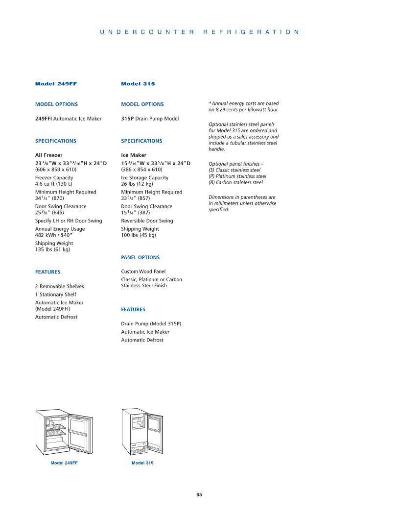
U N D E R C O U N T E R R E F R I G E R A T I O N
Model 315
MODEL OPTIONS
315P Drain Pump Model
SPECIFICATIONS
Ice Maker
153/16"W x 335/8"H x 24"D(386 x 854 x 610)
Ice Storage Capacity26 lbs (12 kg)
Minimum Height Required333/4" (857)
Door Swing Clearance151/4" (387)
Reversible Door Swing
Shipping Weight100 lbs (45 kg)
PANEL OPTIONS
Custom Wood Panel
Classic, Platinum or CarbonStainless Steel Finish
FEATURES
Drain Pump (Model 315P)
Automatic Ice Maker
Automatic Defrost
Model 315Model 249FF
Model 249FF
MODEL OPTIONS
249FFI Automatic Ice Maker
SPECIFICATIONS
All Freezer
237/8"W x 3313/16"H x 24"D(606 x 859 x 610)
Freezer Capacity4.6 cu ft (130 L)
Minimum Height Required341/4" (870)
Door Swing Clearance253/8" (645)
Specify LH or RH Door Swing
Annual Energy Usage482 kWh / $40*
Shipping Weight135 lbs (61 kg)
FEATURES
2 Removable Shelves
1 Stationary Shelf
Automatic Ice Maker(Model 249FFI)
Automatic Defrost
63
*Annual energy costs are basedon 8.29 cents per kilowatt hour.
Optional stainless steel panelsfor Model 315 are ordered andshipped as a sales accessory andinclude a tubular stainless steelhandle.
Optional panel finishes –(S) Classic stainless steel(P) Platinum stainless steel(B) Carbon stainless steel
Dimensions in parentheses arein millimeters unless otherwisespecified.
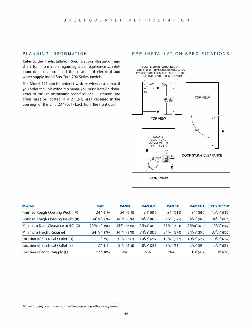
P L A N N I N G I N F O R M A T I O N
Refer to the Pre-Installation Specifications illustration andchart for information regarding area requirements, mini-mum door clearance and the location of electrical andwater supply for all Sub-Zero 200 Series models.
The Model 315 can be ordered with or without a pump. Ifyou order the unit without a pump, you must install a drain.Refer to the Pre-Installation Specifications illustration. Thedrain must be located in a 2" (51) area centered in theopening for the unit, 23" (651) back from the front door.
Model 245 249R 249RP 249FF 249FFI 315 / 315P
Finished Rough Opening Width (A) 24"(610) 24"(610) 24"(610) 24"(610) 24"(610) 151/4"(387)
Finished Rough Opening Height (B) 341/2"(876) 341/2"(876) 341/2"(876) 341/2"(876) 341/2"(876) 341/2"(876)
Minimum Door Clearance at 90˚ (C) 2513/16"(656) 253/8"(644) 253/8"(644) 253/8"(644) 253/8"(644) 151/4"(387)
Minimum Height Required 341/4"(870) 341/4"(870) 341/4"(870) 341/4"(870) 341/4"(870) 333/4"(857)
Location of Electrical Outlet (D) 1"(25) 101/2"(267) 101/2"(267) 101/2"(267) 101/2"(267) 101/2"(267)
Location of Electrical Outlet (E) 2"(51) 81/2"(216) 81/2"(216) 21/2"(63) 21/2"(63) 21/2"(63)
Location of Water Supply (F) 12"(305) N/A N/A N/A 18"(457) 8"(203)
FRONT VIEW
B
LOCATEELECTRICAL
OUTLET WITHINSHADED AREA
E
A
7"
7"
24"
TOP VIEW
DOOR SWING CLEARANCE
90˚ C
TOP VIEW
D
F1"2
23"
LOCATE DRAIN FOR MODEL 315 WITHIN 2" (51) DIAMETER SHADED AREA,23" (584) BACK FROM THE FRONT OF THE
DOOR AND CENTERED IN OPENING
(13)
(584)(610)
(178)
(178)
U N D E R C O U N T E R R E F R I G E R A T I O N
64
Dimensions in parentheses are in millimeters unless otherwise specified.
P R E - I N S T A L L A T I O N S P E C I F I C A T I O N S
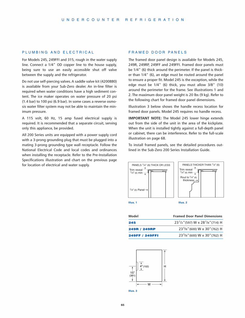
Model Framed Door Panel Dimensions
245 231/2"(597) W x 281/8"(714) H
249R / 249RP 235/8"(600) W x 30"(762) H
249FF / 249FFI 235/8"(600) W x 30"(762) H
W
H
15"(381)
4"(102)
PANELS 1/4" (6) THICK OR LESS
1/4" (6) Panel
Trim reveal 1/4" (6) min
PANELS THICKER THAN 1/4" (6)
Trim reveal 1/4" (6) min
Rout to 1/4" (6)thickness
U N D E R C O U N T E R R E F R I G E R A T I O N
Illus. 1 Illus. 2
65
F R A M E D D O O R P A N E L S
The framed door panel design is available for Models 245,249R, 249RP, 249FF and 249FFI. Framed door panels mustbe 1/4" (6) thick around the perimeter. If the panel is thick-er than 1/4" (6), an edge must be routed around the panelto ensure a proper fit. Model 245 is the exception, while theedge must be 1/4" (6) thick, you must allow 3/8" (10)around the perimeter for the frame. See illustrations 1 and2. The maximum door panel weight is 20 lbs (9 kg). Refer tothe following chart for framed door panel dimensions.
Illustration 3 below shows the handle recess location forframed door panels. Model 245 requires no handle recess.
IMPORTANT NOTE: The Model 245 lower hinge extendsout from the side of the unit in the area of the kickplate.When the unit is installed tightly against a full-depth panelor cabinet, there can be interference. Refer to the full-scaleillustration on page 68.
To install framed panels, see the detailed procedures out-lined in the Sub-Zero 200 Series Installation Guide.
Illus. 3
P L U M B I N G A N D E L E C T R I C A L
For Models 245, 249FFI and 315, rough in the water supplyline. Connect a 1/4" OD copper line to the house supply,being sure to use an easily accessible shut off valvebetween the supply and the refrigerator.
Do not use self-piercing valves.A saddle valve kit (4200880)is available from your Sub-Zero dealer. An in-line filter isrequired when water conditions have a high sediment con-tent. The ice maker operates on water pressure of 20 psi(1.4 bar) to 100 psi (6.9 bar). In some cases a reverse osmo-sis water filter system may not be able to maintain the min-imum pressure.
A 115 volt, 60 Hz, 15 amp fused electrical supply isrequired. It is recommended that a separate circuit, servingonly this appliance, be provided.
All 200 Series units are equipped with a power supply cordwith a 3-prong grounding plug that must be plugged into amating 3-prong grounding type wall receptacle. Follow theNational Electrical Code and local codes and ordinanceswhen installing the receptacle. Refer to the Pre-InstallationSpecifications illustration and chart on the previous pagefor location of electrical and water supply.
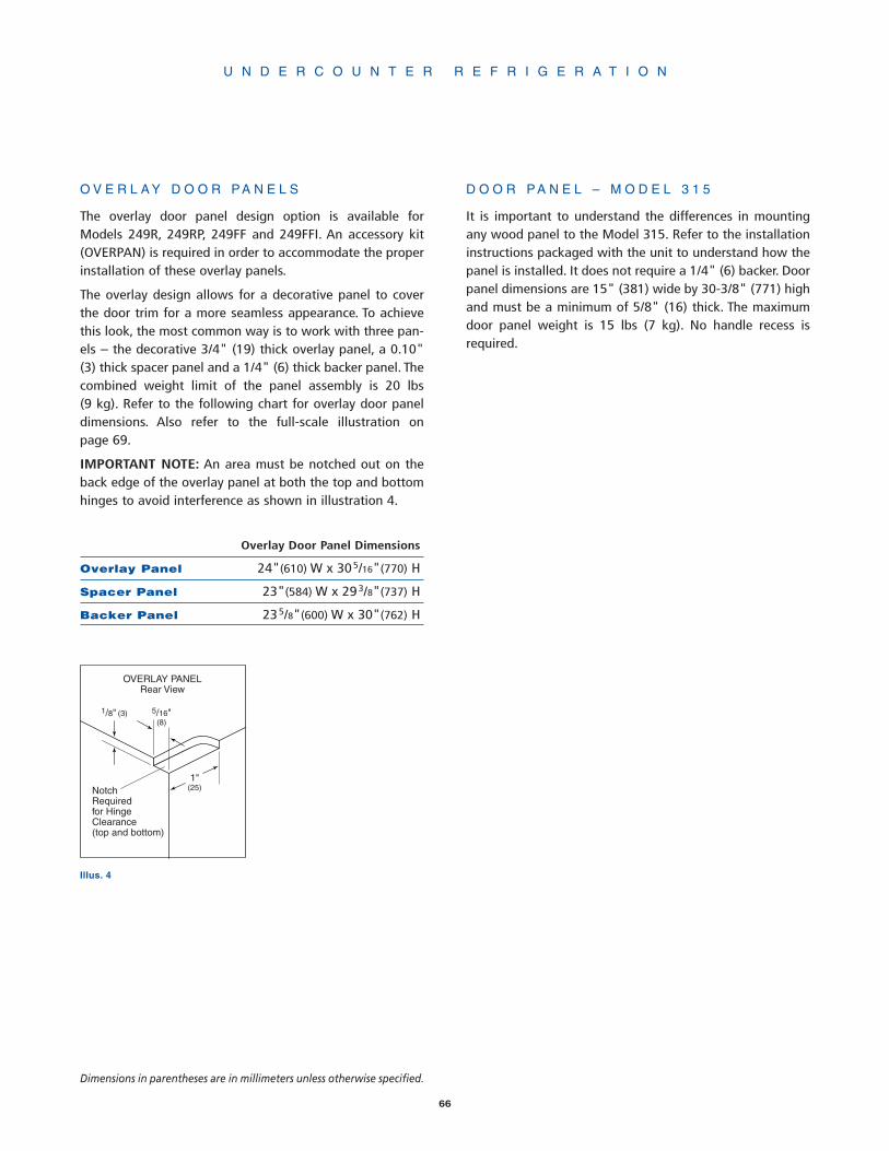
66
U N D E R C O U N T E R R E F R I G E R A T I O N
Dimensions in parentheses are in millimeters unless otherwise specified.
O V E R L A Y D O O R P A N E L S
The overlay door panel design option is available forModels 249R, 249RP, 249FF and 249FFI. An accessory kit(OVERPAN) is required in order to accommodate the properinstallation of these overlay panels.
The overlay design allows for a decorative panel to coverthe door trim for a more seamless appearance. To achievethis look, the most common way is to work with three pan-els – the decorative 3/4" (19) thick overlay panel, a 0.10"(3) thick spacer panel and a 1/4" (6) thick backer panel. Thecombined weight limit of the panel assembly is 20 lbs(9 kg). Refer to the following chart for overlay door paneldimensions. Also refer to the full-scale illustration onpage 69.
IMPORTANT NOTE: An area must be notched out on theback edge of the overlay panel at both the top and bottomhinges to avoid interference as shown in illustration 4.
Overlay Door Panel Dimensions
Overlay Panel 24"(610) W x 305/16"(770) H
Spacer Panel 23"(584) W x 293/8"(737) H
Backer Panel 235/8"(600) W x 30"(762) H
D O O R P A N E L – M O D E L 3 1 5
It is important to understand the differences in mountingany wood panel to the Model 315. Refer to the installationinstructions packaged with the unit to understand how thepanel is installed. It does not require a 1/4" (6) backer. Doorpanel dimensions are 15" (381) wide by 30-3/8" (771) highand must be a minimum of 5/8" (16) thick. The maximumdoor panel weight is 15 lbs (7 kg). No handle recess isrequired.
5/16"(8)
NotchRequiredfor HingeClearance(top and bottom)
1"(25)
OVERLAY PANELRear View
1/8" (3)
Illus. 4

U N D E R C O U N T E R R E F R I G E R A T I O N
67
151/4"(387) MIN.
FRONT VIEW
SHUT-OFFVALVE
WATERFILTERWATER
INLET TUBE
DRAINTUBE
TOP VIEW
SHUT-OFFVALVE
WATERFILTER
341/2"(876) NOMINAL
333/4"(857) MIN.
151/4"(387) MIN.
24"(610)
1/8" (3)
WATERINLETTUBE
DRAINTUBE
LOCATE DRAINWITHIN 2" DIA.AREA 23" BACKFROM FRONT
OF UNIT
FRONT VIEW
SHUT-OFFVALVE
WATERFILTER
WATERINLET TUBE
AIR GAPDEVICE
DRAINTUBE
TOP VIEW
SHUT-OFFVALVE
WATERFILTER
WATERINLET TUBE
DRAINTUBE
AIR GAPDEVICE
24"(609)
1/8" (3)
151/4"(387) MIN.
151/4"(387) MIN.
341/2"(876) NOMINAL
333/4"(857) MIN.
M O D E L S 3 1 5 A N D 3 1 5 P –G R A V I T Y D R A I N O R D R A I N P U M P
This ice maker can be ordered with a pump (Model 315P) orwithout a pump (Model 315). Models without a drain pumpdrain their water by gravity. However, gravity drain modelsmay be converted to pump models through the installationof a drain pump kit and drain pump.
Specific step-by-step instructions are included with thedrain pump kit. Contact your Sub-Zero dealer for specifics.
The drain and inlet water tubes must be plumbed beforeconnecting to the ice maker. For the gravity drain, all hori-zontal runs of drain lines must have a 1/4" (6) per 1' (305)fall. An air gap will likely be required between the ice makerdrain tube and the drain/waste receptacle. A stand pipewith a trap below it would be acceptable for the drain/waste receptacle. Refer to illustration 5 for the Model 315gravity drain and illustration 6 for the Model 315P drainpump.
IMPORTANT NOTE: Poor draining will cause a high rate ofice melting in the bin.
Illus. 5 Illus. 6

68
233/4" (603)TO BACK OF UNIT
237/8" (606)WIDTH OF UNIT
DOOR
TOP VIEW
BOTTOM HINGE EXTENDS 1/4" (6)FROM SIDE OF UNIT
UP TO 31/2" (89) FROM FLOOR
M O D E L 2 4 5 – L O W E R H I N G E
U N D E R C O U N T E R R E F R I G E R A T I O N
Dimensions in parentheses are in millimeters unless otherwise specified.

69
*MODEL 249 OVERLAYMUST EXTEND A MINIMUMOF 1-13/16" (46) BEYONDSURFACE OF ADJOINING
CABINETRY AND MUST BE1" (25) FROM ADJACENT
CABINETRY TO ALLOW THEMAXIMUM DOOR SWING
113/16" (46)
3/4" (19)
1"* (25)
DOOR CLOSED
DOOR PANEL
145˚*
DOOR PANEL
DOOR OPEN @ 145˚
145˚ DOOR OPENING(TOP VIEW)
24" (610)CABINETRY OPENING
O V E R L A Y P A N E L S – M O D E L S 2 4 9 R , 2 4 9 R P, 2 4 9 F F A N D 2 4 9 F F I
Dimensions in parentheses are in millimeters unless otherwise specified.

70
S U B - Z E R O F R E E Z E R C O M PA N Y P R O D U C T S
L I M I T E D W A R R A N T Y
RESIDENTIAL USE ONLY
FULL FIVE YEAR SEALED SYSTEM WARRANTY
LIMITED SIXTH THROUGH TWELFTH YEAR WARRANTY ON THE SEALED SYSTEM
FULL TWO YEAR WARRANTY ON TOTAL PRODUCT*
FULL FIVE YEAR SEALED SYSTEM WARRANTY
For five years from the date of original installation, your Sub-Zero warranty covers all parts and laborto repair or replace any components that prove to be defective in materials or workmanship in thesealed system. The sealed system consists of the compressor, condenser, evaporator, drier and allconnecting tubing.
FULL TWO YEAR WARRANTY*
For two years from the date of original installation, your Sub-Zero warranty covers all parts andlabor to repair or replace any part of the product, which proves to be defective in materials or work-manship.
LIMITED SIXTH THROUGH TWELFTH YEAR SEALED SYSTEM WARRANTY
From the 6th through the 12th year from the date of original installation, your Sub-Zero warrantycovers all parts that prove to be defective in materials or workmanship in the sealed system (partsonly). The sealed system consists of the compressor, condenser, evaporator, drier and all connectingtubing.
TERMS APPLICABLE TO EACH WARRANTY
All service provided by Sub-Zero under the above warranty must be performed by an authorizedSub-Zero service center, unless otherwise specified by Sub-Zero. Service will be provided in thehome during the normal business hours. This warranty applies only to products installed fornormal residential use. Details regarding a non-residential warranty are available upon request.
The warranty applies only to products installed in any one of the fifty states of the United States, theDistrict of Columbia or the ten provinces of Canada. This warranty does not cover any parts or laborto correct any defect caused by negligence, accident or improper use, maintenance, installation,service or repair, including but not limited to improper removal and reinstallation (whether in the unitor at a remote location) of the condensing unit.
THE REMEDIES DESCRIBED ABOVE FOR EACH WARRANTY ARE THE ONLY ONES, WHICHSUB-ZERO WILL PROVIDE, EITHER UNDER THESE WARRANTIES OR UNDER ANY WARRANTYARISING BY OPERATION OF LAW. SUB-ZERO WILL NOT BE RESPONSIBLE FOR ANY CONSE-QUENTIAL OR INCIDENTAL DAMAGES ARISING FROM THE BREACH OF THESE WARRANTIESOR ANY OTHER WARRANTIES, WHETHER EXPRESS, IMPLIED OR STATUTORY.
Some states do not allow the exclusion or limitation of incidental or consequential damages, so theabove limitation or exclusion may not apply to you. This warranty gives you specific legal rights andyou may also have other legal rights, which vary from state to state.
To receive parts and/or service and the name of the Sub-Zero authorized service center nearest you,contact your Sub-Zero dealer, distributor or Sub-Zero Freezer Company, Customer Service Depart-ment, P.O. Box 44130, Madison Wisconsin, 53744-4130, call (800) 222-7820 or e-mail us [email protected].
*Stainless Steel (classic, platinum and carbon) doors, panels and product frames are covered by alimited 60 day parts and labor warranty for cosmetic defects.

SUB-ZERO® is a registered trademark of Sub-Zero Freezer Company, Inc.
®

S U B - Z E R O F R E E Z E R C O M P A N Y, I N C .
4 7 1 7 H a m m e r s l e y R o a d M a d i s o n , W i s c o n s i n 5 3 7 1 1 ( 8 0 0 ) 2 2 2 - 7 8 2 0 ( 6 0 8 ) 2 7 1 - 2 2 3 3 w w w. s u b z e r o . c o m
3 7 5 8 3 8 1 S Z D G 8 / 0 4
®