Embed Size (px)
Citation preview

Cascade is a Registered Trademark of Cascade Corporation
cascadecorporation
ERVICE MANUALS45G-160G
Rotators
Manual Number 6073955-R3

CONTENTS
i 6073955-R3
Page
INTRODUCTION, Section 1Introduction 1Special Definitions 1
PERIODIC MAINTENANCE, Section 3Daily Maintenance 21000-Hour Maintenance 22000-Hour Maintenance 3Rotate Function Evaluation 3
TROUBLESHOOTING, Section 4General Procedures 4
Truck System Requirements 4Tools Required 4Troubleshooting Chart 4
Plumbing 5Hosing Diagram 5Circuit Schematic 6
Rotation Function 7Supply Circuit Test 7Rotation Without Load 7Rotation With Load 8Rotation Drift Test 9
SERVICE, Section 5Attachment Removal 10Drive Group 12
Drive Group Removal and Installation 12Drive Group Disassembly and Service 12Drive Group Reassembly 14
Drive Motor 16Drive Motor Removal and Installation 16Drive Motor Disassembly 17Drive Motor Inspection 19Drive Motor Reassembly 19
Drive Control Valve 21Drive Control Valve Service 21
Base Unit 22Capscrew Torque Inspection 22Bearing Assembly Removal and Inspection 23Fork Bar Service 25Bearing Seal Service 25
SPECIFICATIONS, Section 6Specifications 26
Hydraulics 26Auxiliary Valve Functions 26Truck Carriage 2645G-65G Torque Values 2780G, 100G Torque Values 28130G, 160G Torque Values 29Determining Load Torque Requirements 30

INTRODUCTION
6073955-R3 1
1.1 IntroductionThis manual provides the Periodic Maintenance, Troubleshooting, Service and Specifications for Cascade 45G-160G Rotators.
In any communication about the attachment, refer to the product ID number stamped on the nameplate as shown. If the nameplate is missing, the numbers can be found stamped on the left, front side of the faceplate between the fork bars.
IMPORTANT: All hoses, tubes and fittings on these attachments are JIC.
NOTE: Specifications are shown in both US and (Metric) units. All fasteners have a torque value range of ±10% of stated value.
1.2 Special DefinitionsThe statements shown appear throughout this Manual where special emphasis is required. Read all WARNINGS and CAUTIONS before proceeding with any work. Statements labeled IMPORTANT and NOTE are provided as additional information of special significance or to make your job easier.
CAUTION - A statement preceded by CAUTION is information that should be acted upon to prevent machine damage.
IMPORTANT - A statement preceded by IMPORTANT is information that possesses special significance.
NOTE - A statement preceded by NOTE is information that is handy to know and may make your job easier.
WARNING - A statement preceded by WARNING is information that should be acted upon to prevent bodily injury. A WARNING is always inside a ruled box.
Nameplate(front side of faceplate)
WARNING: Fork size affects attachment capacity. Refer to Installation Instructions 6073002, installation Step 13. Verify capacity for truck nameplate.
+
7
@
123
+
A2-Z
Cascade Corporation • www.cascorp.com • Icons & Patents: www.cascorp.com/support 6095754
RR1197.eps
45G-RRB-10A
PTL 604920-1R0
45G-RRB-10A
PTL604920-1R0

2 6073955-R3
PERIODIC MAINTENANCE
RR0825.eps
RR0828.eps
Left Side
Ball Race Grease Fitting (A)
2.1 Daily InspectionPrior to each shift of truck operation, complete the following procedures:
• Check for loose or missing bolts, worn or damaged hoses, and hydraulic leaks.
• Check that fork locking pins and end bar keepers are installed and functional.
• Check decals and nameplate for legibility.
• Tighten rotator drive capscrews to a torque of 66 ft.-lbs. (90 Nm).
• Check rotator drive gearcase lubricant level. Lubricant should be up to bottom of fill plug or check plug hole. If necessary, fill with Cascade Rotator Drive Lubricant, Part No. 656300, or SAE 90 wt. gear lube (AGMA 'mild' 6 EP Gear Oil). Replace plug.
• Check rotation performance using a typical load. Refer to Rotate Function Evaluation, Section 2.4 of this manual.
• Lubricate rotation bearing assembly ball race (A), and gear (B) with EP-2 grease (Whitmore 'Omnitask' or equivalent). Rotate in 90° increments and grease in each position.
• Tighten lower mounting hook capscrews to a torque of:
CL II/III – 120 ft.-lbs. (165 Nm) CL IV – 235 ft.-lbs. (320 Nm)
• Check sample of bearing assembly to faceplate capscrews for proper torque value. Refer to Technical Bulletin TB183 or the Service section 4.5-1 of this Manual for checking and replacement procedures.
• Check sample of baseplate assembly capscrews for proper torque value. Refer to Technical Bulletin TB183 or the Service section 4.5-1 of this manual for checking and replacement procedures.
2.2 1000-Hour MaintenanceEvery time the lift truck is serviced or every 1000 hours of truck operation, complete the following maintenance procedures:
• If equipped, lubricate plungers on hydraulic or electronic 180° stop valves.
Back (Driver's) View
Fork Carriage Bars, Keepers
Gear Grease Fitting (B)
WARNING: After completing any service procedure, always test the attachment through five complete cycles. First test empty, then test with a load to make sure the attachment operates correctly before returning it to the job.
WARNING: A sampling of faceplate and baseplate bearing assembly capscrews must be checked for proper torque at 1000 hours (see TB183). A complete inspection is required every 2000 hours. Failure to keep the capscrews tightened can result in attachment damage and serious injury.
GearGreaseFitting (B)
End Cover Hole (level and fill hole)
Rotator Drive Capscrews
Bearing Capscrews (Access all through hole in baseplate)
Lower Mounting Hook Capscrews
Baseplate Capscrews
Rotator Drive Capscrews
End Cover Hole (level and fill hole)

36073955-R3
PERIODIC MAINTENANCE
2.3 2000-Hour MaintenanceAfter each 2000 hours of truck operation, in addition to the 1000-hour maintenance, perform the following procedures:
• Check all rotation bearing capscrews for proper torque value. Refer to Technical Bulletin TB183 or the Service section 4.5-1 of this manual for checking and replacement procedures.
• Fork Inspection – After 2000 hours of truck operation, forks in use shall be inspected at intervals of not more than 12 months (for single shift operations) or whenever any defect or permanent deformation is detected. Severe applications will require more frequent inspection.
Fork inspection shall be carried out by trained personnel to detect any damage that might impair safe use. Any fork that is defective shall be removed from service. Reference ANSI B56.1-2005.
Inspect for the following defects:
− Surface cracks
− Straightness of blade and shank
− Fork angle
− Difference in height of fork tips
− Positioning lock
− Wear on fork blade and shank
− Wear on fork hooks
− Legibility of marking
NOTE: Fork Safety Kit 3014162 contains wear calipers, inspection sheets and safety poster. Also available is fork hook & carriage wear gauge 209560 (Class II), 209561 (Class III) and 6105257 (Class IV).
2.4 Rotate Function EvaluationThe following procedure should be performed every 1000 hours of truck/attachment operation:
1 Engage the forks with a typical bin load that is within the capacity of the attachment/truck combination.
2 Raise the load the minimum amount to avoid hitting the floor during rotation.
3 Rotate the load Clockwise (CW) 45° and stop. No rotational drift should be observed within 30 seconds.
4 Rotate the load Counterclockwise (CCW) 45° to return to the initial position.
5 Rotate the load Counterclockwise (CCW) 45° and stop. No rotational drift should be observed within 30 seconds.
6 Rotate the load Counterclockwise (CCW) 45° to return to the initial position.
7 Repeat steps 3 thru 6 two times to confirm observed conditions.
• If no rotational drift is observed during the evaluation, no action is required.
• CAUTION: If rotational drift is observed during the evaluation, contact the Cascade Service Department to assist with troubleshooting and symptom resolution.
RR1453.eps
180°
0°
45°45°
34 5 6
Driver’s View Forward
CCW
CW
Forward
RC5823.eps

TROUBLESHOOTING
4 6073955-R3
3.1 General Procedures3.1-1 Truck System Requirements
3.1-2 Tools RequiredIn addition to a normal selection of hand tools, you will need:
• Inline Flow Meter Kit:20 GPM (75 L/Min.) - Cascade Part No. 671477
• Pressure gauge Kit:5000 psi (345 bar) - Cascade Part No. 671212. Two kits required.
• Assorted fittings and hoses to adapt gauge and flow meter to the components being tested
3.1-3 Troubleshooting Chart
• Truck hydraulic pressure should be with in the range shown in Specifications, Section 5.1. PRESSURE TO THE ATTACHMENT MUST NOT EXCEED 2300 psi (160 bar).
• Hydraulic flow should be within the volume range as shown in Specifications, Section 5.1.
• Hydraulic fluid supplied to the attachment must meet the requirements as shown in Specifications, Section 5.1.
Determine All The FactsIt is important that all the facts regarding the problem are gathered before beginning service procedures. The first step is to talk to the equipment operator. Ask for a complete description of the malfunction. The following guidelines can then be used as a starting point to begin troubleshooting procedures:
Rotator Circuit
• No rotation.
• No rotation with load at rated capacity.
• Rotation in only one direction.
To correct one of these problems, refer to Section 3.3
• The attachment drifts from its rotated position.
To correct one of these problems, refer to Section 3.3-4.
GA0013.eps
GA0014.eps
(2) No. 8-12 JIC/O-Ring Flow Meter
(2) No. 6-8 JIC Reducer
Pressure Gauge No. 6-6 Hose
No. 6 and No. 8 JIC Swivel Tee
No. 4-6 Pipe/JIC No. 6-8 JIC Reducer
No. 4, No. 6, and No. 8 JIC/O-Ring
Flow Meter Kit:671477
Pressure Gauge Kit:671212
WARNING: Before servicing any hydraulic component, relieve pressure in the system. Turn the truck off and move the truck auxiliary control valves several times in both directions.
After completing any service procedure, test the attachment through several cycles. First test the attachment empty to bleed any air trapped in the system to the truck tank. Then test the attachment with a load to be sure it operates correctly before returning to the job.
Stay clear of the load while testing. Do not raise the load more than 4 in. (10 cm) off the floor while testing.

56073955-R3
TROUBLESHOOTING
RR1312.eps
3.2 Plumbing3.2-1 Hosing Diagram
ROTATE COUNTERCLOCKWISE
PRESSURERETURN
NOTE: For ROTATE CLOCKWISE, reverse the colors shown.
Dual Drive Box
Hose Terminal
Hose Reel
To HoseReel
ROTATE TruckAuxiliaryValve
CW
CW
CCW
CCW

TROUBLESHOOTING
6 6073955-R3
RR1441.eps
3.2-2 Circuit Schematic
Single Drive Group Dual Drive Group
CCW CCW
CW CW
Drive Control Valvewith Counterbalance Cartridges(Current Valve)
Drive Control Valvewith Counterbalance Cartridges(Current Valve)
Drive Control Valvewith Check Cartridges or Spring-Type(Early Valves)
To Hose Reel
Truck Pump
Truck Tank
Truck Relief
Hose Reel
Truck Auxiliary Valve (ROTATE)

76073955-R3
TROUBLESHOOTING
3.3 Rotation FunctionThere are four potential problem areas that could affect the rotation function.
• Operator may be handling the load incorrectly. Loads may be too heavy or rotated off-center, exceeding capacity of the attachment. Refer to Operator’s Guide for suggested handling procedures.
• Low hydraulic pressure and/or flow from lift truck.
• Worn or defective motor.
• Worn or defective drive assembly or frame bearing assembly.
3.3-1 Supply Circuit Test1 Check the pressure delivered by the truck. Refer to
the truck Service Manual. Pressure to the attachment must not exceed 2300 psi (160 bar), measured at the carriage hose terminal.
2 Check the flow volume at the carriage hose terminal. Refer to Section 5.1-1 for recommended flow volumes. If the truck pressure and flow are correct, proceed with the Rotation circuit pressure test.
3 Check for external leaks.
WARNING: Before removing any hoses, relieve pressure in the hydraulic system. Turn the truck off, then open the truck auxiliary control valve(s) several times in both directions.
3.3-2 Rotation Without Load1 Install pressure gauges to the motor fittings.
2 Start the truck and rotate the attachment without a load. While rotating, note pressure readings of both gauges.
• If the attachment rotates in one direction faster than the other, or rotates in one direction only, the drive control valve may need repair. Refer to Section 4.4.
• If the lower gauge reading exceeds 500 psi (35 bar), there is excessive back pressure in the supply circuit. Check for restrictions such as numerous fittings and hose sizes less than No. 8, etc.
RR0545.eps
Install Pressure Gauges
RR0555.eps
Install Flow Meter
RR1317.eps
Install Pressure Gauges
TROUBLESHOOTING
8 6073955-R3
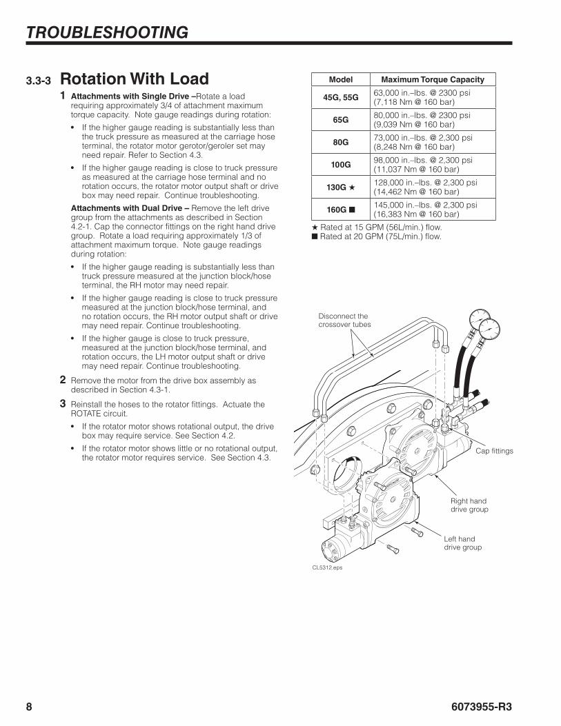
3.3-3 Rotation With Load1 Attachments with Single Drive –Rotate a load
requiring approximately 3/4 of attachment maximum torque capacity. Note gauge readings during rotation:
• If the higher gauge reading is substantially less than the truck pressure as measured at the carriage hose terminal, the rotator motor gerotor/geroler set may need repair. Refer to Section 4.3.
• If the higher gauge reading is close to truck pressure as measured at the carriage hose terminal and no rotation occurs, the rotator motor output shaft or drive box may need repair. Continue troubleshooting.
Attachments with Dual Drive – Remove the left drive group from the attachments as described in Section 4.2-1. Cap the connector fittings on the right hand drive group. Rotate a load requiring approximately 1/3 of attachment maximum torque. Note gauge readings during rotation:
• If the higher gauge reading is substantially less than truck pressure measured at the junction block/hose terminal, the RH motor may need repair.
• If the higher gauge reading is close to truck pressure measured at the junction block/hose terminal, and no rotation occurs, the RH motor output shaft or drive may need repair. Continue troubleshooting.
• If the higher gauge is close to truck pressure, measured at the junction block/hose terminal, and rotation occurs, the LH motor output shaft or drive may need repair. Continue troubleshooting.
2 Remove the motor from the drive box assembly as described in Section 4.3-1.
3 Reinstall the hoses to the rotator fittings. Actuate the ROTATE circuit.
• If the rotator motor shows rotational output, the drive box may require service. See Section 4.2.
• If the rotator motor shows little or no rotational output, the rotator motor requires service. See Section 4.3.
CL5312.eps
Disconnect the crossover tubes
Cap fittings
Right hand drive group
Left hand drive group
Model Maximum Torque Capacity
45G, 55G 63,000 in.–lbs. @ 2300 psi(7,118 Nm @ 160 bar)
65G 80,000 in.–lbs. @ 2300 psi(9,039 Nm @ 160 bar)
80G 73,000 in.–lbs. @ 2,300 psi(8,248 Nm @ 160 bar)
100G 98,000 in.–lbs. @ 2,300 psi(11,037 Nm @ 160 bar)
130G ★ 128,000 in.–lbs. @ 2,300 psi(14,462 Nm @ 160 bar)
160G ■ 145,000 in.–lbs. @ 2,300 psi(16,383 Nm @ 160 bar)
★ Rated at 15 GPM (56L/min.) flow.■ Rated at 20 GPM (75L/min.) flow.

96073955-R3
TROUBLESHOOTING
3.3-4 Rotation Drift Test1 Position forks parallel to the floor.
2 Place a mark at the top center of the baseplate and bearing. Place rotation limit marks at 20° (12 in., 30.5 cm) at each side of the top center on the faceplate. All marks should be viewable by the driver.
NOTE: If the faceplate is raised, mark 12 in. (30.5 cm) from center.
3 With the forks parallel to the floor, pick up a load.
4 Lift a load 15 in. (38 cm) off the floor to provide clearance for rotation drift test.
5 Rotate load CW to 20° align marks and wait 30 seconds. Observe if drift occurs.
• If drift occurs, the rotator drive components require service. Refer to Section 4.2.
6 Rotate load CCW to 20° align marks and wait 30 seconds. Observe if drift occurs.
• If drift occurs, the rotator drive components require service. Refer to Section 4.2.
RR1321.eps
Mark at top centerMarks at 20° (12 in., 30.5 cm) each side of the center

10 6073955-R3
SERVICE
2
4.1 Attachment Removal1 Rotate the attachment to position the forks parallel to
the ground.
2 Remove the fork bar keepers at each end of the top carriage bar. For reassembly, tighten the capscrews to a torque of:
Capscrew Type:45G−160G− 200 ft.-lbs. (270 Nm)
Bar Type:45G−65G− 66 ft.-lbs. (90 Nm)
Clean and dry bar type capscrews and threaded holes. Apply Loctite 242 (blue) to capscrews.
3 If equipped with fork restraint kit, loosen capscrews on outer restraint and remove from fork bar. For reassembly, install outer restraint against the fork. Tighten capscrews to:
45G, 55G – 166 ft.-lbs. (225 Nm)65G-160G – 295 ft.-lbs. (400 Nm)
4 Release the spring lock on the top of each fork. Remove the forks from the fork bar.
RR0509.eps
4
OR
OR
RR0511.eps
4
Bar Type Fork Keeper
Capscrew Type Fork Keeper
RR1319.eps
3

SERVICE
116073955-R3
RR0510.eps
ADJUST
RC0368.eps
cascade
®
C-6755
14-1
RR0548.eps
4.1 Attachment Removal (continued)5 Disconnect the lower hooks.
Bolt On Hooks – Remove the lower mounting hooks. For reassembly, tighten the capscrews to a torque of:
Class II/III – 120 ft.-lbs. (165 Nm)Class IV – 235 ft.-lbs. (320 Nm)
Clean and dry capscrews and threaded holes. Apply Loctite 242 (blue) to capscrews.
Quick Change Hooks – Pull out the locking pins, slide the hooks down and reinstall the pins in the lower holes. For reassembly, slide the hooks up and install the pins in the top holes.
Carriage Bar
Lower Hook
Locking Pin
Guide
Lower Hook inunlocked position
BOLT-ON HOOKS
QUICK-CHANGE HOOKS
5
7
6 Disconnect the hydraulic hoses to the drive motor. Tag the hoses for reassembly.
7 Attach a suitable overhead hoist to the upper fork bar. Remove the attachment from the truck. Lay the attachment face down on a pallet with the drive group upward.
8 For installation, reverse the above procedures.
WARNING: Verify that the overhead hoist and chains or straps are rated for the weight of the attachment. Refer to nameplate for attachment weight.
WARNING: Before removing any hoses, relieve pressure in the hydraulic system. Turn the truck off, then open the truck auxiliary control valve(s) several times in both directions.

12 6073955-R3
SERVICE
RR0549.eps
RR0520.eps
4.2 Drive Group4.2-1 Drive Group Removal
and Installation1 Remove the attachment from the truck as described in
Section 4.1.
2 Dual Drive – Disconnect the crossover tubes from the drive control valve.
3 Remove the four capscrews fastening the drive group to the baseplate. For reassembly, tighten the capscrews to a torque of 66 ft.-lbs. (90 Nm).
4 For reassembly, reverse the above procedures with the following exceptions:
• After the drive group has been reinstalled, check the gearcase oil level. Oil must be up to the bottom of the fill plug hole. If necessary, fill with Cascade Gear Lube Part No. 656300 or equivalent SAE 90 wt. lube (AGMA 'mild' 6 EP Gear Lube).
34
4 37
5
2 6
Cover Plate
Housing
End Cover Housing
4.2-2 Drive Group Disassembly and Service1 Remove the drive group from the baseplate as
described in Section 4.2-1.
2 Lay the drive group, pinion down, on two 4 x 4 in. (10 x 10 mm) wood blocks placed on both sides of the pinion.
3 Remove the four capscrews fastening the cover plate to the housing.
4 Remove the center capscrew plug from the cover plate and install an M10 capscrew with a minimum thread length of 2 in. (50 mm). Remove the cover plate by turning the capscrew clockwise while lightly tapping around the sides of the cover plate.
5 Drain oil from the housing.
6 Remove the three capscrews fastening the end cover to the housing.
7 Remove the drive motor as described in Section 4.3-1.

SERVICE
136073955-R3
RR0521.eps
RR0522.eps
RC2111.eps
8 Tap the worm and bearing assembly out through the end-cover side of the housing. Remove the opposite outer bearing race through the motor side of the housing.
8
9
10
11
Bearing outer race
Pinion shaft key
NOTE: Two types of large pinion bearing used: sealed bearing and bearing with separate seal (shown)
Pinion gear
Worm
Worm Gear
Seal (if equipped)
Housing Pinion bearing
8
OR
Washers
NOTE: The drive group being serviced may or may not be assembled with the washers shown on the worm.
CAUTION: When replacing a worm or worm gear, the serial number of the attachment and whether washers are or are not installed on the worm must be supplied to identify the correct replacement parts.
9 Press the pinion gear, seal, pinion bearings and worm ring gear out of the housing as an assembly.
10 Remove the snap ring from the pinion gear shaft. Press the pinion gear bearing from the worm ring gear and cover plate pinion bearing. Remove the pinion shaft key.
11 Press the pinion gear out of the housing pinion bearing.
12 Clean and inspect all components. Remove all dried sealant residue. Replace all worn items. Remove any burrs or sharp edges with emery cloth.
4.2-2 Drive Group Disassembly and Service (continued)

14 6073955-R3
SERVICE
RC2118.eps
RR0550.eps
RC2648.eps
RC2125.eps
RC0178.eps
4.2-3 Drive Group ReassemblyBuild up the pinion/worm gear assembly vertically with the pinion gear down.
1 Pinion with seal and non-sealed bearing – Position the seal against the pinion gear, spring-side facing housing. Apply Loctite 271 (red) to the bearing seating area as shown. Press a non–sealed housing bearing onto the pinion shaft.
NOTE: If installing a sealed bearing with external seal, pry out bearing seals and then press into pinion shaft. Remove excess Loctite.
Pinion with sealed bearing – No external seal is used. Apply Loctite 271 (red) to the bearing seating area as shown. Press housing bearing onto the pinion shaft. Remove excess Loctite.
CAUTION: Make sure Loctite does not squeeze into the seal or bearings.
2 Preheat worm gear to 200° F (93° C). Install the key, worm gear, cover plate pinion bearing and snap ring on the pinion.
3 Apply Loctite 271 (red) to the housing seating area and shoulder for the housing pinion bearing. Install the complete pinion assembly into the housing. Remove excess Loctite.
CAUTION: Make sure Loctite does not squeeze into the seal or bearings.
4 Install the worm's outer bearing race in the drive motor side of the housing. Make sure the race taper is inward as shown.
5 Install the drive motor as described in Section 4.3-1.
6 Install the worm, bearings, and washers (if equipped) in the housing. Fully engage the worm with the drive motor shaft. Install the remaining outer bearing race. Make sure the race taper is inward as shown.
6
4
5
1
2
Pinion gear
Key
3Housing
Bearing Seating Area
External Seal Housing
Pinion Bearing
Worm Gear, Bearing, Snap Ring
PINION WITH SEAL AND NON-SEALED BEARING
Seal Seating Area
PINION WITH SEALED BEARING
Housing Pinion Bearing(Sealed)

SERVICE
156073955-R3
RR0551.eps
RR0552.eps
7 Temporarily install the end cover without shims. Tighten the capscrews sequentially in 10 ft.-lb. (15 Nm) increments to 20 ft.-lbs. (30 Nm).
8 Measure the gap between the end cover and housing in three places with a feeler gauge or 'Plastigage' thread and determine the minimum gap.
9 Drive Group with Worm Washers – The worm washers and bearings require 0.020–0.025 in. (0.50–0.64 mm) preload. Subtract the preload numbers from the feeler gauge measurement to determine the shims required between the end cover and housing. See sample below.
In this case two 0.020 in. (0.50 mm) yellow shims would be installed to equal 0.040 in. (1.0 mm). Refer to shims listed below.
Drive Group without Worm Washers – Choose a combination of end cover shims equal to the minimum gap measured plus the next higher 0.005 in. (0.12 mm) increment. See examples below:
• For 0.025–0.029 in. (0.635–0.736 mm) measured gap, use 0.030 in. (0.762 mm) total shim thickness.
• For 0.010–0.014 in. (0.254–0.356 mm) measured gap, use 0.015 in. (0.381 mm) total shim thickness.
• For 0.009 in. (0.228 mm) or less, use one 0.010 in. (0.254 mm) shim. A minimum of one 0.010 in. (0.254 mm) shim is required for proper seal.
NOTE: Shim Service kit 670578 contains the shims listed. A minimum of one 0.010 in. (0.25 mm) shim is required to seal against leakage:
10 Remove the end cover. Apply Loctite 515 sealant (Cascade Part No. 668184) to both surfaces of the shims. Install the shim pack and end cover. Tighten the capscrews to a torque of 65 ft.-lbs. (88 Nm). Remove excess sealant.
11 With the gearcase laying flat, fill with 2-1/4 Cups (18 fluid ounces or 540 ml) of Cascade Gear Lube Part No. 656300, or SAE 90 wt. gear lube (AGMA 'mild' 6EP Gear Lube).
12 Install the cover plate and gasket. If the gaskets shows porosity, apply Loctite 515 sealent to cover face. Install the four cover plate capscrews and tighten to 16 ft.-lbs. (22 Nm). Install the center hole plug.
13 Reinstall the drive group on the baseplate as described in Section 4.2-1.
12
Cover plate
11
10
9
7
8HousingEnd cover
RR0553.eps
0.063 in.- 0.025 in.
0.063 in.- 0.020 in.
(Feeler gauge measurement)(Preload)
0.038 in. to 0.043 in. (Shim thickness range)
4.2-3 Drive Group Reassembly (continued)
Qty Part No. Color Thickness1111
674513670574671757671758
BlueBrownPink
Yellow
0.005 in. (0.125 mm)0.010 in. (0.254 mm)0.015 in. (0.381 mm)0.020 in. (0.508 mm)

16 6073955-R3
SERVICE
CCW
CW
RR1202.eps
4.3 Drive Motor4.3-1 Drive Motor Removal and
Installation1 Remove the attachment from the lift truck as described
in Section 4.1.
2 Remove the drive group from the attachment as described in Section 4.2-1.
3 Remove the fill plug and drain the lubricant from the drive group.
4 Lay the drive group, pinion down, on two 4 x 4 in. (10 x 10 cm) wood blocks placed on both sides of the pinion gear.
5 Remove the four capscrews and special lockwashers fastening the drive control valve to the drive motor. Keep track of the two O-rings between the drive control valve and drive motor. For reassembly, tighten the capscrews to 15 ft.-lbs. (20 Nm).
WARNING: Before removing hydraulic lines, relieve pressure in the hydraulic system. Turn the truck off and open the truck auxiliary control valves several times in both directions.
56
6
8
43
87
Drive Motor(Current)
Drive Motor
O-rings
Fill Plug (two locations)
Drive Control Valve
6 Remove the three capscrews fastening the motor flange (or adapter plate) to the gearcase housing. Tap on the drive motor with a rubber mallet to separate the drive motor (or drive motor with adapter plate) from the gearcase housing.
7 Early Drive Motors – Remove the four capscrews fastening the adapter plate to the drive motor. Separate the motor from the adapter plate.
8 For reassembly, reverse the above procedures except as follows:
• Early Drive Motors – Apply Loctite 515 sealant (Cascade Part No. 668184) to both sides of the drive motor/adapter plate gasket. Apply sealant to the threads of the four drive motor capscrews. Install the gasket and adapter plate to the drive motor. Tighten capscrews to 40 ft.-lbs. (54 Nm).
• Apply sealant to both sides of the motor/gearcase (or adapter plate/gearcase) gasket. Apply sealant to the threads of the three motor flange (or adapter plate) capscrews. Install the motor (or motor with adapter plate) and gasket to the gearcase housing. Tighten the capscrews to 65 ft.-lbs. (88 Nm).
• Fill the drive group with fill with 18 fluid ounces (540 ml) of Cascade Gear Lube Part No. 656300, or SAE 90 wt. gear lube (AGMA 'mild' 6EP Gear Lube).
Adapter Plate(if equipped)
Early Drive Motors

SERVICE
176073955-R3
RR1199.eps
RR0841.eps
RR0863.eps
RR0632.eps
Housing O-Ring ▲
3
6
7
45
Pressure Seal ▲
Wiper Seal ▲
Flange Seal ▲
Housing
Flange(609XXXX or greater)
Flange(608XXXX or less)
Load Bearing Race
Thrust Bearing
Output Shaft
Splined Drive
Spacer Plate
Geroler Set
End Cap
Capscrews
Capscrews
Gerotor Set
2
8
Spacer Plate
O-Ring ▲
O-Ring ▲
O-Ring ▲
Brass Shim ▲
3 Make a scribe across the drive motor, inline with the capscrew and drive motor’s port surface.
4 Clamp drive motor in a soft-jawed vise across the flange with the output shaft downward.
5 Remove all capscrews from the end cap.
6 Remove altogether the end cap, geroler/gerotor set and spacer plate. The splined drive should remain in place with this group.
7 Remove the O-rings from the end cap, geroler/gerotor set and housing.
8 Turn the drive motor over, clamping the housing across the port area with the flange upward.
4.3-2 Drive Motor DisassemblyCascade provides service replacement parts for the seals indicated with a ▲ below. Due to cost, if other parts need replacement, the complete drive motor assembly should be replaced.
1 Remove the drive motor from the drive group as described in Section 4.3-1.
IMPORTANT: Clean the outside of the drive motor and service in a clean, dust-free work area. Use a soft-jawed vise for all service procedures.
2 Remove O-rings from housing.

18 6073955-R3
SERVICE
RR0860.eps
RR0859.eps
RR0843.eps
RR0858.eps
9 Remove the four Loctited capscrews from the flange with a X10 Torx Socket. Do not use an impact wrench.
CAUTION: Thread sealant used on the capscrews may require a small amount of heat to the housing to remove the capscrews. Use a temperature indicator to prevent overheating the housing.
10 Turn the flange 45° clockwise.
11 Remove the flange and output shaft by pushing the output shaft from under the housing and pulling up on the tapered portion of the output shaft.
12 Remove the flange and thrust bearing from the output shaft.
13 Remove the load bearing race and flange seal from the flange.
14 Remove the wiper seal and pressure seal from the flange using a seal removal tool or modified screwdriver as shown.
NOTE: Remove the seals by pushing from the back side, as shown.
15 Remove the brass shim from the flange.
10
1114
Modified Screwdriver
Flange (early design)
Flange
9
14
1513
Flange
12
RR1200.eps
45°
4.3-2 Drive Motor Disassembly (continued)

SERVICE
196073955-R3
RR0861.eps
RR0862.eps
4.3-4 Drive Motor Reassembly1 Install the brass shim into the pressure seal side of the
flange. Install wiper seal and pressure seal into the flange. The pressure seal must be seated evenly.
2 Place the bearing race in the flange, seated evenly with pressure seal and flange.
3 Lubricate the flange seal with petroleum jelly and seat in lip of flange on the pressure seal side, as shown.
4 Install thrust bearing onto the output shaft.
5 Install the flange onto the output shaft with the pressure seal side against the output shaft.
6 Clamp housing in the vise with the flange side facing upward.
7 Install the output shaft/flange assembly into the housing.
8 Apply Loctite sealant 242 (blue) or equivalent to the four holes of the housing and the four capscrews. Wipe away any excess sealant. Install the four Torx capscrews and tighten in a criss-cross pattern to 250 in.-lbs. (28 Nm).
IMPORTANT: Capscrews must be clean and dry.
RR0633.eps
Brass Shim
Wiper Seal
Pressure SealBearing Race
Flange
Flange Seal
4.3-3 Drive Motor Inspection• Remove all Loctite residue from the threaded holes.
• Clean all parts with solvent and blow dry. Do not use paper or cloth towels.
• Inspect all parts for small nicks, burrs or scratches. Remove imperfections with emery cloth. Replace parts where imperfections could not be removed.
• Inspect the flange seal seats for scratches. Check for cracks in the flange area that could cause leakage.
8
1
2 3
7
4 5
Output Shaft

20 6073955-R3
SERVICE
7
5
31
6
4
272
4
6
1
3
5
RR1201.eps
Spacer Plate
O-Ring
Gerotor (or Geroler)
O-Ring
End Cap
14
Star Point
Star Point
Scribe Mark
12
Short Spline O-Ring
15
13
RR0647.eps
9 Turn the housing over and clamp across the flange with the output shaft taper facing down.
10 Lubricate the O-rings and install into the housing, geroler/gerotor set and endcap grooves.
11 Align the ouput shaft timing dot with the screw hole that is aligned to the port surface. Use the scribe mark to help with the alignment.
12 Use the drive splines to align the gerotor/geroler star point with the capscrew hole, as shown.
CAUTION: Geroler spacers can fall out.
13 Assemble together the endcap with O-ring, gerotor/geroler set with O-ring, drive (short spline end into gerotor/geroler set) and spacer.
IMPORTANT: Make sure O-Rings are properly seated.
14 Install endcap assembly onto housing while aligning the scribe marks and capscrew holes. Make sure the drive engages with output shaft.
15 Install the capscrews into the end cap. Tighten the capscrews using an alternating cross pattern to 240 in.-lbs. (27 Nm).
Splined Drive
Timing Dot
RR0627.eps
Timing Dot on Output Shaft
Screw hole that is aligned with port surface.
Port Surface
11
RR0674.eps
10
Splined Drive
4.3-4 Drive Motor Reassembly (continued)

SERVICE
216073955-R3
CCWCW
RR1442.eps
ccwcw
RR0524.eps
WARNING: Before removing hydraulic lines, relieve pressure in the attachment hydraulic system. Turn the truck off and move the auxiliary control valves several times in both directions.
4.4 Drive Control Valve4.4-1 Drive Control Valve Service
1 Disconnect the hydraulic hoses to the drive control valve. Tag hoses for reassembly.
2 Dual Drive – Disconnect the crossover tubes from the drive control valve.
3 Remove the four capscrews fastening the drive control valve to the drive group. Keep track of the two O-rings between the drive control valve and drive motor. For reassembly, tighten the capscrews to 15 ft.-lbs. (20 Nm).
4 Remove the plug fittings and drive control valve internal parts.
5 Clean all parts with clean solvent. Remove any burrs or sharp edges with emery cloth.
6 Inspect the internal ball seats for imperfections that would keep the balls from seating fully.
7 For reassembly, reverse the above procedures except as follows:
• Note the correct direction of the internal conical springs (spring type valve).
• Install new O-rings and back-up rings on the cartridges as shown (cartridge type valve).
IMPORTANT: If replacing cartridges, replace in pairs.
3
O-Rings
Drive Control Valve
Back-up RingsBack-up Rings
O-RingsO-Rings Check ValveCartridge (Early)
Counterbalance Cartridge (Current)
CCW
CW
RC0197.eps
6
74
Body
SPRING TYPE CARTRIDGE TYPE
Check Valve Cartridges (Early)
CounterbalanceCartridges (Current)
1
GA0486.epsGA0487.eps
7

22 6073955-R3
SERVICE
RR0659.eps
RR0658.eps
1 Baseplate-to-Bearing Assembly Capscrews
Baseplate
2 Bearing Assembly-to-Faceplate Capscrews
Baseplate
Faceplate
Back (Driver's) Views
Access Plug
Bearing Assembly (Baseplate removed)
4.5 Base Unit4.5-1 Bearing Assembly –
Capscrew Torque Inspection500-Hour InspectionEvery 500 hours perform the following inspection:
1 Check the accessible baseplate capscrews above upper mounting hooks for an initial torque of:
45G-100G – 77 ft.-lbs. (105 Nm)130G – 65 ft.-lbs. (90 Nm)160G – 165 ft.-lbs. (225 Nm)
Tighten capscrews to 10 ft.-lbs. (14 Nm) above initial torque. Mark each capscrew after checking.
• If any baseplate capscrews are loose, rotate or broken, replace all baseplate fasteners as described in Section 4.5-2.
• If capscrews do not rotate, continue with faceplate capscrew inspection in Step 2.
2 If equipped with access plug, remove the access plug from the back of the baseplate. Rotate the attachment to position the forks parallel to the ground. Check three capscrews closest to the access hole for an initial torque of:
45G-130G – 80 ft.-lbs. (110 Nm)160G – 200 ft.-lbs. (275 Nm)
Tighten capscrews 10 ft-lbs. (14 Nm) above initial torque. Mark each capscrew after checking.
• If any faceplate capscrews are loose, rotate or broken, replace all faceplate fasteners as described in Section 4.5-2.
• If capscrews do not rotate, inspection is complete.
2000-Hour InspectionEvery 2000 hours perform the following inspection:
NOTE: The attachment must be removed from truck to provide access to all bearing assembly capscrews. For faceplate capscrews, remove the baseplate (shown) or use access hole to provide access to all faceplate capscrews (see Section 4.5-3).
1 Check all baseplate and faceplate capscrews fastened to the bearing assembly. Tighten until torque is 10 ft.-lbs. (14 Nm) above torque values listed above. Mark each capscrew after checking.
• If any capscrews are loose, rotate or broken, replace all capscrews as described in Section 4.5-3.
• If capscrews do not rotate, inspection is complete.
RR0660.eps

SERVICE
236073955-R3
RR1203.eps
RR0525.eps
4.5-2 Bearing Assembly Removal and Installation1 Remove the attachment from the lift truck as described
in Section 4.1.
2 Remove the drive group from the attachment as described in Section 4.2-1.
3 Remove upper mounting hooks and adapter plate (if included). For reassembly tighten the capscrews to the torque values below:
45G–100G CL II/III – 120 ft.-lbs. (165 Nm)80G/100G CL IV Hook – 235 ft.-lbs. (320 Nm)80G/100G CL IV Plate – 120 ft.-lbs. (165 Nm)130G,160G – 320 ft.-lbs. (435 Nm)
Clean and dry Class II/III upper mounting capscrews and threaded holes. Apply Loctite 242 (blue) to capscrews.
4 Remove center spacer. For reassembly, clean and dry capscrews and threaded holes. Apply Loctite 242 (blue) to capscrews and tighten to 48 ft.-lbs. (65 Nm).
5 Remove the capscrews fastening the baseplate to the bearing assembly. For reassembly, tighten the capscrews using the following technique:
WARNING: Install short capscrews in counterbored holes only. Use lockwashers if supplied in kit.
Baseplate/Bearing Assembly Capscrews –
A Clean and dry capscrews and threaded holes.
45G-100G – Apply Loctite 242 (blue) to capscrews. Threads must be clean and dry for new Loctite to cure properly.
B Tighten using the alternating cross to 40 ft.-lbs. (55 Nm).
C Tighten using the alternating cross pattern to the final torque value, then double-torque by backing off one-half turn and immediately retightening to the final torque value of:
45G-100G – 77 ft.-lbs. (105 Nm)130G – 65 ft.-lbs. (90 Nm)160G – 165 ft.-lbs. (225 Nm)
CAUTION: Do not reuse old capscrews or washers. Use new hardware kit when installing a new bearing assembly.
6 Attach two eyebolts to the baseplate as shown. Attach an overhead hoist and lift away the baseplate.
7 Check condition of the baseplate seal. Refer to Section 4.5-4 for service.
3
4
57
6
Baseplate
Bearing AssemblyFaceplate
RR0533.eps
Cross Pattern Tightening Sequence.
2
RR0534.eps
3Class IVAdapter Plate
WARNING: Verify that the overhead hoist and chains or straps are rated for the weight of the attachment. Refer to nameplate for attachment weight.

24 6073955-R3
SERVICE
R
RR0528.eps
RR0530.eps
RR1204.eps
8 Remove the capscrews fastening the bearing assembly to the faceplate. For reassembly, tighten the capscrews using the following technique:
Bearing Assembly/Faceplate Capscrews –
A Clean and dry capscrews and threaded holes. 45G-100G – Apply Loctite 242 (blue) to capscrews. Threads must be clean and dry for new Loctite to cure properly.
B Tighten using the alternating cross pattern to 40 ft.-lbs. (55 Nm).
C Tighten using the alternating cross pattern to the final torque value, then double-torque by backing off one-half turn and immediately retightening the final torque value of:
45G-130G – 80 ft.-lbs. (110 Nm)160G – 200 ft.-lbs. (275 Nm)
CAUTION: Do not reuse old capscrews or washers. Use new hardware kit when installing a new bearing assembly.
9 Attach two eyebolts to the bearing assembly as shown. Attach an overhead hoist and lift away the bearing assembly.
10 For reassembly, reverse the above procedures except as follows:
• When installing the rotation bearing assembly on the faceplate, align and position the heat-treated overlap zone 'R' on the ring gear with the outer race grease fitting as shown.
45G − 25° above horizontal 55G/65G − 45° above horizontal80G/100G − 39° above horizontal130G − 6° below horizontal160G − 0° at the horizontal
• Apply NLGI No. 0 Grease to the teeth of the bearing assembly ring gear.
• After mounting the attachment on the lift truck, apply chassis grease to the bearing assembly grease fitting. Rotate the attachment slowly while applying grease.
8
9
10
Bearing Assembly
Faceplate
Baseplate
Cross Pattern Tightening Sequence
Heat-treated Overlap Zone 'R'
4.5-2 Bearing Assembly Removal and Installation (continued)

SERVICE
256073955-R3
4.5-3 Fork Bar Service1 Tighten the fork bar capscrews using the tightening
sequence shown:
45G/55G– 200 ft.-lbs. (270 Nm)65G– 400 ft.-lbs. (540 Nm)80G/100G/130G/160G– 395 ft.-lbs. (535 Nm)
RR0531.eps
60
8 46
81 5 92
2 1 3 75
4 73
65G sequence shown
4.5-4 Bearing Seal Service1 Remove attachment from the lift truck as described in
Section 4.1
2 Remove the drive group from the attachment as described in Section 4.2-1.
3 Remove upper mounting hooks and baseplate as described in Section 4.5-2 step 3 through 6.
4 Bring baseplate to vertical position.
5 Remove the seal from the baseplate.
NOTE: On 80G/100G Rotators, remove capscrew and plate before removing the seal. For reassembly apply Loctite 242 (blue) to capscrews and tighten to 15 ft.-lbs. 20 Nm.
6 Clean baseplate ring surface seal with solvent and dry.
7 Install new seal, firmly pressing adhesive side to baseplate ring.
8 For reassembly reverse the above procedures except as follows:
• Apply NLGI No. 0 Grease to the teeth of the bearing assembly ring gear.
• After mounting the attachment on the lift truck, apply chassis grease to the bearing assembly grease fitting. Rotate the attachment slowly while applying grease.
RR0597.eps
45G-65G Seal
80G-100G SealPlate
Capscrew
RR0676.eps
6
7

26 6073955-R3
SPECIFICATIONS
GA0388.eps
GA0126.eps
5.2 Auxiliary Valve Functions
Hoist Up
Tilt Forward
Rotate CCW
Tilt Back Rotate CW
Hoist Down
GA0126.eps
Truck Relief Setting2300 psi (160 bar) Maximum
Truck Flow Volume ➀Min. ➁ Recommended Max. ➂
45G – 160G 5 GPM(20 L/min.)
10 GPM(38 L/min.)
15 GPM(56 L/min.)
➀ Cascade Revolving Clamps are compatible with SAE 10W petroleum base hydraulic fluid meeting Mil. Spec. MIL-0-5606 or MIL-0-2104B. Use of synthetic or aqueous base hydraulic fluid is not recommended. If fire resistant hydraulic fluid is required, special seals must be used. Contact Cascade.
➁ Flow less than recommended will result in reduced system performance.
➂ Flow greater than maximum can result in excessive heating, reduced system performance and short hydraulic system life.
Hoses and FittingsNo. 8 with 13/32 in. (10 mm) minimum ID.
5.1 Hydraulics
WARNING: Truck control handle and attachment function activation shown here conforms to ANSI/ITSDF B56.1 (ISO 3691) recommended practices. Failure to follow these practices may lead to serious bodily injury or property damage. End user, dealer and OEMs should review any deviation from the practices for safe operation.

276073955-R3
SPECIFICATIONS
5.3 Truck Carriage
GA0389.eps
A
Carriage Mount Dimension (A) ITA (ISO)
Minimum Maximum
Class IIClass IIIClass IV
14.94 in. (380.0 mm)18.68 in. (474.5 mm)23.44 in. (595.5 mm)
15.00 in. (381.0 mm)18.74 in. (476.0 mm)23.50 in. (597.0 mm)

28 6073955-R3
SPECIFICATIONS
Ref. Fastener Size Ft.-lbs. Nm
1 Upper Hook Capscrews ▲ M16 120 165
2 Faceplate/Bearing Capscrews ▲■ M12 80 110
3 Rotator Drive Capscrews M12 66 90
4 Adapter Plate/Housing Capscrews (Early) M12 65 85
5 Drive Control Valve Capscrews M8 15 20
6 Adapter Plate/Motor Capscrews ◆ M10 40 55
7 Motor Flange/Housing Capscrews (Current) M12 65 85
8 Quick Change Hooks Capscrews ▲ M16 120 165
9 Lower Center Spacer Capscrews ▲ M12 48 65
10 Bolt-On Lower Hook Capscrews ▲ M16 120 165
11 Baseplate/Bearing Capscrews ▲■ M12 77 105
12 Lower Spacer Capscrews ▲ M16 120 165
13 Housing End Cover Capscrews ● M12 66 90
14 Fork Keeper Capscrew (Current) M16 200 270
15 Fork Bar Capscrews 45G, 55G M16 200 27065G M20 400 540
16 Fork Keeper Capscrews (Early) ▲ M16 66 90
17 Fork Restraint Capscrews M16 166 225▲ Apply Loctite 242 (Blue)◆ Apply Loctite 271 (Red)● Apply Loctite 515 Sealant■ Double Torque
RR1346.eps
RR1333.eps
Front View
5.4 Torque Values5.4-1 45G-65G Torque Values
Fastener torque values for the 45G-65G Rotators are shown in the table below in both US and Metric units. All torque values are also called out in each specific service procedure throughout this manual.
1
6
11
9
1514
10 8
54 7
3
12
1617
NOTE: All fasteners have a torque value range of ±10% of stated value.
Back (Driver’s) View
RR1345.eps
CurrentEarly
2 13

296073955-R3
SPECIFICATIONS
RR1347.eps
12
1012 13
54
3
11
11
12 13
14 15 16
Class III
Class III Class IV
5.4-2 80G, 100G Torque ValuesFastener torque values for the 80G-100G Rotators are shown in the table below in both US and Metric units. All torque values are also called out in each specific service procedure throughout this manual.
Ref. Fastener Size Ft.-lbs. Nm
1 Upper Hook CapscrewsClass III M16 120 165Class IV M20 235 320
2 Upper Hook Adapter Capscrews M16 120 165
3 Faceplate/Bearing Capscrews ▲■ M12 80 110
4 Housing End Cover Capscrews● M12 65 85
5 Rotator Drive Capscrews M12 66 90
6 Adapter Plate/Housing Capscrews ● M12 63 88
7 Drive Control Valve Capscrews M8 15 20
8 Adapter Plate/Motor Capscrews ◆ 3/8 40 55
9 Motor Flange/Housing Capscrews (Current) M12 65 85
10 Baseplate/Bearing Capscrews ▲■ M12 77 105
11 Lower Hook CapscrewsClass III M16 120 165Class IV M20 235 320
12 Lower Spacer Capscrews 5/8 or M16 120 165
13 Lower Center Spacer Capscrews M12 48 65
14 Fork Keeper Capscrews M16 200 270
15 Fork Bar Capscrews M20 395 535
16 Fork Restraint Capscrews M20 295 400▲ Apply Loctite 242 (Blue)◆ Apply Loctite 271 (Red)● Apply Loctite 515 Sealant■ Double Torque
NOTE: All fasteners have a torque value range of ±10% of stated value.
RR1334.eps
Back (Driver’s) View
Front View
8
76 9
RR1345.eps
CurrentEarly

30 6073955-R3
SPECIFICATIONS
5.4-3 130G, 160G Torque ValuesFastener torque values for the 130G, 160G Rotators are shown in the table below in both US and Metric units. All torque values are also called out in each specific service procedure throughout this manual.
Ref. Fastener Size Ft.-lbs. Nm
1 Upper Hook Capscrews M20 320 435
2 Faceplate/Bearing Capscrews ■M12 80 110M16 203 275
3 Rotator Drive Capscrews M12 66 90
4 Baseplate/Bearing Capscrews ■M12 66 90
M16 165 225
5 Housing End Cover Capscrews● M12 75 100
6 Lower Hook Capscrews M20 235 320
7 Lower Center Spacer Capscrews M12 66 90
8 Motor Flange/Housing Capscrews (Current) M12 65 85
9 Drive Control Valve Capscrews M8 15 20
10 Fork Keeper Capscrews M16 200 270
11 Fork Bar Capscrews M20 390 530
12 Fork Restraint Capscrews M20 295 400● Apply Loctite 515 Sealant■ Double Torque
RR1335.eps
RR1336.eps
RR1337.eps
11
7 7
3 355
11
9
2 2
10
8
4 4
12
6 6Single Drive
Back (Driver’s) ViewDual Drive
Back (Driver’s) View
Front View
RR1348.eps

316073955-R3
SPECIFICATIONS
RR0541.eps
5.5 Determining Load Torque RequirementsIMPORTANT: Positioning the load as close to center as possible will reduce the torque requirements and increase truck stability.
To check that an attachment will handle a specific load, calculate the torque requirements as follows:
1 Weigh the load to be handled. Example: 1500 lbs.
2 Determine the center of the faceplate. Tape newspaper or cardboard over the hole of the attachment. Draw a line between a set of faceplate holes that are 180˚ apart. Repeat for a second set of holes. Where they cross is the center point of the attachment.
3 Determine the vertical off-center distance of the load. Measure from the load vertical centerline to the attachment vertical centerline.
4 Determine the horizontal off-center distance of the load. Measure from the load horizontal centerline to the attachment horizontal centerline.
5 Off-center distance calculation.
• Square the vertical centerline measurement.
Example: (3 in.)² = 9 in.
• Square the horizontal centerline measurement.
Example: (4 in.)² = 16 in.
• Add these two figures together.
Example: 9 in. + 16 in. = 25 in.
• Determine the square root and you have the total off-center distance.
Example: 25 in. = 5 in. off-center distance
• Multiply the total off-center distance by the load weight and you have the torque required to handle the load. Compare this figure to the attachment specifications in the chart.
Example: 5 in. x 1500 lbs. = 7500 in.-lbs. Load
3in.
4in.
2
Model Maximum Torque Capacity
45G, 55G 63,000 in.-lbs. @ 2300 psi(7,118 Nm @ 160 bar)
65G 80,000 in.-lbs. @ 2300 psi(9,039 Nm @ 160 bar)
80G 73,000 in.-lbs. @ 2,300 psi(8,248 Nm @ 160 bar)
100G 98,000 in.-lbs. @ 2,300 psi(11,037 Nm @ 160 bar)
130G ★ 128,000 in.-lbs. @ 2,300 psi(14,462 Nm @ 160 bar)
160G ■ 145,000 in.-lbs. @ 2,300 psi(16,383 Nm @ 160 bar)
★ Rated at 15 GPM (56 L/min.) flow.■ Rated at 20 GPM (75 L/min.) flow.
Load Horizontal Centerline
Attachment Horizontal Centerline
Load
Ver
tical
Cen
terli
ne
Atta
chm
ent
Vert
ical
Cen
terli
ne

c© Cascade Corporation 2018 03-2018 Part Number 6073955-R3
Do you have questions you need answered right now? Call your nearest Cascade Service Department.Visit us online at www.cascorp.com
AMERICASCascade CorporationU.S. Headquarters2201 NE 201stFairview, OR 97024-9718Tel: 800-CASCADE (227-2233)Fax: 888-329-8207
Cascade Canada Inc.5570 Timberlea Blvd.Mississauga, OntarioCanada L4W-4M6Tel: 905-629-7777Fax: 905-629-7785
Cascade do BrasilPraça Salvador Rosa,131/141-Jordanópolis, São Bernardo do Campo - SPCEP 09891-430Tel: 55-13-2105-8800Fax: 55-13-2105-8899
EUROPE-AFRICACascade Italia S.R.L.European HeadquartersVia Dell’Artigianato 137030 Vago di Lavagno (VR) ItalyTel: 39-045-8989111Fax: 39-045-8989160
Cascade (Africa) Pty. Ltd.PO Box 625, Isando 160060A Steel RoadSparton, Kempton ParkSouth AfricaTel: 27-11-975-9240Fax: 27-11-394-1147
ASIA-PACIFICCascade Japan Ltd.2-23, 2-Chome,Kukuchi NishimachiAmagasaki, Hyogo Japan, 661-0978Tel: 81-6-6420-9771Fax: 81-6-6420-9777
Cascade Korea121B 9L Namdong Ind. Complex, 691-8 Gojan-DongNamdong-KuInchon, KoreaTel: +82-32-821-2051Fax: +82-32-821-2055
Cascade-XiamenNo. 668 Yangguang Rd. Xinyang Industrial ZoneHaicang, Xiamen CityFujian ProvinceP.R. China 361026Tel: 86-592-651-2500Fax: 86-592-651-2571
Cascade India Material Handling Private LimitedOffice No.21, 3rd Floor, Lokmanya House, Plot No.44, Sr. No. 89/90, CTS No.950, Lokmanya Colony, Paud Rd., Kothrud, Pune-411038 Phone : +91 955 250 3060
Cascade Australia Pty. Ltd.1445 Ipswich RoadRocklea, QLD 4107AustraliaTel: 1-800-227-223Fax: +61 7 3373-7333
Cascade New Zealand15 Ra Ora DriveEast Tamaki, AucklandNew ZealandTel: +64-9-273-9136Fax: +64-9-273-9137
Sunstream IndustriesPte. Ltd.18 Tuas South Street 5Singapore 637796Tel: +65-6795-7555Fax: +65-6863-1368