Embed Size (px)
Citation preview
6.3 1984 to 1992: Buildings designed to Loadings Code NZS 4203:198413
6.3.1 90 Armagh Street: Craigs Investment House building
Current status
The building is still standing, but its future is not known to the Royal Commission.
Figure 88: View from the north-west (source: Becker Fraser Photos)
6.3.1.1 Introduction
Craigs Investment House at 90 Armagh Street was designed during 1985 and 1986. Building permits were issued by the CCC in 1986 (the foundations and the main structure were the subject of separate permits); the completion date is not certain from the information available. The building is 10 storeys high plus a basement, with a total height of 35.1m (Figure 88). It is located approximately 25m from the banks of the Avon River.
6.3.1.2 Structural system
6.3.1.2.1 Foundations

The foundations comprise a concrete raft 300–900mm thick with the retaining walls to the basement 300mm cast in situ concrete.
6.3.1.2.2 Structural floors
The ground floor is a 250mm thick cast in situ slab that acts as a diaphragm to transfer seismic loads to the perimeter basement wall on the northern side. The elevated floors are formed by double-tee precast reinforced concrete units, with a 65mm in situ concrete topping reinforced with standard 665 mesh reinforcement. These floors act as diaphragms. The location of the stairs and lifts in the tower creates a significant cut-out in the floors, which is offset to the south-west of the building’s centre lines (see Figure 89). The double-tee units in the floors span in the north–south direction. They are supported by moment resisting frames on the southern and northern sides of the building (on grid lines 1 and 6 respectively) and by an intermediate moment resisting frame on grid line 3.
Figure 89: Typical upper level plan
6.3.1.2.3 Lateral force system
The east–west lateral force resistance in the tower is provided primarily by the reinforced concrete moment resisting frames on the southern and northern sides of the building, with a minor contribution (due to its low relative lateral stiffness) of the moment resisting frame on line 3. The lateral force resistance in the north–south direction is provided by the moment resisting frames on the western and eastern walls of the building, on grid lines A and J (see Figure 89). The frames were built from precast units. These were tee-shaped units consisting of a column with a beam on top (see Figure 90). The longitudinal reinforcement in the beams projected by 1100mm, which allowed it to be lapped within in situ concrete joints between the precast units (see Figure 90). The column sections measure 900mm by 450mm and the beams are 900mm deep by 320mm wide. The longitudinal reinforcement in the columns is Grade 380 and in the beams it is Grade 275. To establish continuity between the beams there is a cast in situ joint in the mid-span region of the bays. Continuity of the columns is provided by joining the longitudinal column reinforcement with mechanical splices (NBM type U).

Figure 90: Typical details of precast beam column units
There are no corner columns in the tower. As shown in Figure 89, the beams at the elevated levels of the building near the corners cantilever out from the column to support a diagonal beam across each corner. The supports to the diagonal beam act as pin connections. This allows differential movements to occur between the east–west and north–south frames.
Both the moment resisting frames on the northern and southern sides of the building have three bays bounded by columns, with an additional bay at each end that contains the diagonal corner beams. The moment resisting frame close to grid line 3 has four bays. The beam and column dimensions in this frame are smaller than the moment resisting frames on the building perimeter, reducing its lateral stiffness. The primary function of the frame on grid line 3 is to provide support for gravity loads. The moment resisting frames on the eastern and western sides of the building, on grid lines A and J, each have two bays bounded by columns with an additional bay at each end containing the diagonal corner beam.
6.3.1.2.4 Stairs
There is a single stairway in the building and the detail shown on the drawings indicates that the flights from each level are seismically separated at mid-storey height. There was no indication that egress via the stairs was compromised by any of the earthquakes.
Precast panels
Precast concrete wall panels 100mm thick were fitted to the southern and eastern walls. Each panel was supported by two mechanical splices cast into the beam, with two fixing brackets that had slotted holes to fix the lower level of the panel and allow for lateral movement.
6.3.1.3 Performance of the building
The Royal Commission was assisted in the assessment of the performance of this building by a report prepared by Spencer Holmes.
6.3.1.3.1 Foundations and precast panels

There has been no information provided to the Royal Commission indicating that the building was damaged by earthquakes before 22 February 2011. As a result of the February earthquake, the building tilted by about 0.5 degrees towards the south-east, which equates to a tilt of about 300mm at the top of the building. We infer that this tilt was due to liquefaction and lateral spreading of the land causing the foundations to settle and rotate. The heavy precast concrete wall panels on the southern and eastern sides, and the additional forces on the foundation soils from the Victoria Square apartments building at 100 Armagh Street (on the eastern side), would have contributed to the lateral deflection to the south-east. We note that the Victoria Square building is also assessed, in section 6.4.1 of this Volume.
There has been damage to glazing, which was due to a clash with a decorative feature on the Victoria Apartments building as well as crushed drainage pipes in the seismic gap between the buildings. The damage indicates that there had been minor pounding against the adjacent structure.
Little damage was found in the structure of the foundations other than the rotation and settlement described above, which was likely to be due to liquefaction of sand and silt layers in the foundations. Appreciable liquefaction was observed in the vicinity of the building.
The precast panel walls of the eastern and southern sides were not damaged, indicating that the seismic separation provided for these was effective.
6.3.1.3.2 Moment resisting frames
The moment resisting frames in general appear to have performed as expected. Below level 7 some single cracks were seen in the beams at the column faces. However, in some cases a fan of diagonal cracks had formed in a similar pattern, as has been observed in many laboratory tests.
Above level 7, the cracking in the beam-column joint transitioned into a crack to the column at the underside of the joint that extended to above the bottom horizontal beam reinforcement, where it passed through the beam-column joint zone. The high-frequency ground motion provided a possible explanation for the horizontal cracking observed. The vertical spectral accelerations for the sites where ground motion was measured for a period of close to 0.1 seconds ranged from 1.5–2.4g (refer to the Carr report14). If the frequency of vibration of the beams in the vertical direction was close to 0.1 seconds, the high accelerations could account for the observed cracking.
In a number of cases horizontal cracks had formed in the beams in the mid-span region where the longitudinal bars from adjacent precast units in the same frame were lapped into the in situ concrete. In some cases the concrete below the lapped reinforcement had spalled. The laps as detailed would have satisfied the requirements in NZS 3101:200612 for lapped splices. It was not clear why cracking and spalling was observed at these locations, as the stress in the bars there should not have been high. It is noted that the clear gap between the lapped longitudinal bars is 42mm, which was equal to 1.3 bar diameters.
There was some damage to the diagonal corner beams. These beams were supported by pin joints located in the beams, which cantilever towards the corners. The movement allowed to accommodate the relative movement between the two cantilevered beams appears to have been inadequate for the relative movements induced in the February earthquake. Consequently some damage was induced in the diagonal and cantilever beams.
6.3.1.3.3 Floor diaphragms

The diaphragms in the first to fifth floors had cracked, with crack widths of 4mm. It appeared that the 665 mesh in these floors had fractured at these cracks. The higher floors may have been damaged in a similar manner but they were not examined for this cracking. On each floor, the cracks ran in a north–south direction across the floor between the eastern side of the opening in the floor for the stairs and lifts, to near grid line 6 on the northern side of the building (see Figure 89). We consider that the formation of these cracks is due to elongation of the beams associated with the formation of plastic hinges in the east–west moment resisting frames on grid lines 1, 3 and 6.
6.3.1.4 Conclusions
We conclude that:
1. The building was designed with ductile moment resisting frames providing the lateral force resistance. Its performance in the February 2011 earthquake is consistent with the design philosophy inherent in the structural design standards current at the time of design and at present. The beams in the moment resisting frames developed cracks that remained open because of yielding of the reinforcement. In some cases fan-shaped cracks formed; these remained open, indicating that the yield zone had extended for some distance along the beam. Single column face cracks are typical in beam-column joint tests conducted at curvature ductility levels of one third the maximum permitted in NZS 3101:200612. Other cracks may have formed in the beams but unless the reinforcement had yielded at these cracks they would close and be difficult to notice in an inspection.
2. The tear in the floor diaphragms is consistent with beam plastic hinge formation and the associated elongation in these plastic hinges, which applied tension to the floors.
3. There was some spalling in the lap zones of the longitudinal reinforcement located in the mid-span region of the beams within in situ concrete. There is no clear explanation for this damage. The laps conformed to the requirements for lapped splices in NZS 3101:200612. The limited horizontal spacing between the bars may have contributed to this cracking, but this spacing is within the limits in NZS 3101:200612.
4. The principal problem with the building was the differential settlement of the foundations, which was likely due to liquefaction of the foundation soils below the spread foundations.
6.3.2 20 Bedford Row: Bedford Row Public Car park building
Current status
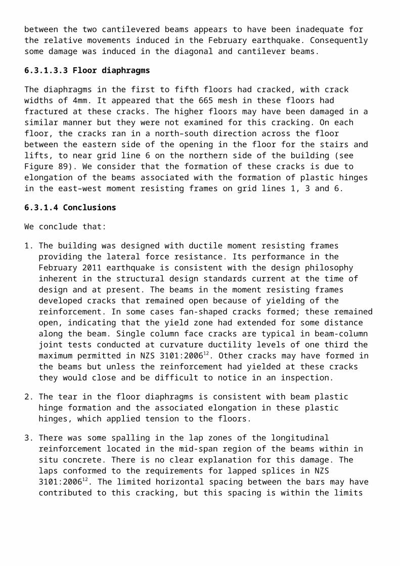
Demolished.
Figure 91: View of Bedford Row Public Car park building from Bedford Row, looking south-east
6.3.2.1 Introduction
The Bedford Row Public Car park was a multi-level car park building with frontages to both Lichfield Street and Bedford Row. It was six storeys high, with each storey on the eastern and western sides offset by half a storey, to give a total of 12 levels. These levels were linked by ramps. The total plan size was about 35m by 40m.
The design and approval for the building both occurred in 1987. We are not sure when construction was completed but expect that it was some time in 1988. The design certificate for the building verified that it was designed to the NZS 4203:198413 Loadings Code and the concrete construction was to be in accordance with NZS 3101. This is presumed to be a reference to NZS 3101:198211, as that Standard applied at the time.
6.3.2.2 Foundations and ground floor

The foundations were shallow ground beams to the perimeter and through the middle (running north–south). These beams were supported on the east and west sides of the building with piles of unknown depth. The ground floor was an unreinforced concrete slab on grade.
6.3.2.3 Building structure
The above-ground floors were 500mm deep double-tee prestressed precast concrete floor units spanning about 17m, with a 65mm concrete topping reinforced with 664 mesh. The floor units were supported on a corbel to the east and west sides of the building (see cross-section B–B, Figure 94) and by precast beams at the centre line of the building. The beams were in turn supported by rebates on a central row of precast columns (see cross-section A–A, Figure 95). An outline of the structural arrangement is shown in Figure 92. The ramps were built using 220mm deep double-tee units spanning about 10m between two beams. The eastern and western walls were 200mm thick precast tilt-up concrete panels to a height of 6.27m, with a further 6.9m of 200mm thick blockwork. The walls on lines 1, 2 and 7 were made from precast panels.
Figure 92: Floor plan
Figure 93: Cross-section C–C
Figure 94: Cross-section B–B
Figure 95: Cross-section A–A
The primary lateral force resistance in the north–south direction was provided by the in-plane actions of the eastern and western walls, which were constructed with precast tilt-up panels 4035mm in width. The walls were extended above the panels by reinforced concrete blockwork. In the east–west direction the shear walls along the Lichfield Street and Bedford Row frontages were 240mm thick cast in situ reinforced concrete. These were not continuous along the frontages, and on the Bedford Row side comprised a double wall on either side of the stairwell/liftshaft.
Precast concrete spandrel panels were fixed on the northern and southern faces of the building to act as balustrades to each level.
Most of the stairs were precast flights that were tied into cast in situ landings at the top of each flight. The lower support may have been sliding in most cases but the drawings are not entirely clear in this matter.
The floors, which were required to act as diaphragms to distribute the seismic forces to the structural walls, provided part of a complex load path. The floor diaphragms lacked an adequate continuous tension chord along the eastern and western walls. In addition, some of the induced membrane forces within the diaphragms were required to be transferred to the resisting walls by inclined ramps.
6.3.2.4 Performance of the building
The Royal Commission was assisted in the assessment of the performance of this building by a report prepared by Spencer Holmes Ltd.
The building was placarded green, “Inspected – no restriction on use or occupation” after the September earthquake. There has been no information provided to the Royal Commission that identifies damage to the building as the result of earthquakes up until the Boxing Day aftershock. After this event, the building was placarded red “Do not approach or enter this building” and a notice issued under section 124 of the Building Act 2004, on the premise that the building was dangerous. This was because cover concrete had spalled and it was considered that loose sections could dislodge in a significant aftershock, endangering the public. Concrete also spalled on a central column on level 10. Loose areas of concrete were removed and the building was opened up to level 9 later in January 2012; the opening of upper levels was delayed until the level 10 column was repaired.
The February earthquake resulted in significant damage to the building and as a result it has now been demolished. The most obvious damage was the failure of the support of one of the precast central beams that supported the double-tee floor system at level 3. The photograph in Figure 96 was taken at level 1 (ground level) and shows that the beam supporting level 3 lost support, resulting in the double-tee units collapsing onto a number of vehicles in the car park at level 1.
Figure 96: Collapse of the double-tee units from level 3
6.3.2.5 Discussion
The lateral forces induced by the earthquake in the east–west direction were transmitted to the northern and southern walls by the diaphragm action of the floor slab and the inclined ramps that connected each level of the building. To transmit the seismic forces to the northern and southern

walls the ramps had to sustain tension and compression forces. Under tension in the ramps there was an upward component of force that acted in consequence of the change in grade above the beams (see cross-section C–C, Figure 93). We consider that this component would have been sufficient to separate the in situ concrete from the supporting beam, resulting in some damage to the concrete at the junction between the ramps and the floor diaphragms.
Seismic-induced forces in the north–south direction were resisted by the eastern and western walls, which, as noted previously, were constructed from precast tilt-up panels, with reinforced block work in the higher levels. Some diagonal cracking and sliding shear was observed in these walls. The seismic forces were transmitted to these walls by the continuity between the topping concrete on the double-tees. This was established by reinforcement bent out from the wall panels and into the in situ concrete on top of the precast double-tee units where it lapped the 664 mesh reinforcement. The individual wall panels acted as cantilevers to resist the in-plane lateral forces. This action led to small vertical displacements being induced at the junction between the panels. The floor was continuous across the junctions between the precast panels. The relative vertical movement across at the junctions, caused by the flexural action in the panels, damaged the floor and in some cases also damaged the double-tee units in the vicinity of the walls.
The level 3 floor appears to have partially collapsed when the concrete failed on the underside of a rebate in the central columns. The detail is shown in Figure 97. The precast beams that supported the 500mm deep double-tee units were held in place in the rebates of the central columns by 24mm bars that extended into the rebate from the column into ducts in the beams. Once assembled, the ducts were grouted (see Figures 97 and 98).
Figure 97: Support detail for beam and double-tee units on the central columns

Figure 98: Undamaged connection at top; the lower connection has failed (largely unseen)
There was no connection between the in situ concrete on the precast double-tee units, the rectangular support beam and the column. The only way that lateral force could be transmitted between the double-tee units and the support beam was through friction. We consider that, under the high lateral forces generated in the February earthquake, the lateral friction force applied to the precast beam was sufficient to cause the beam to rock over the outside edge of the rebate in the column. The gap left between the double-tee unit and the top surface of the rebate would have been insufficient to prevent a wedging action. The resultant pressure on the lower surface of the rebate was sufficient to cause the concrete below the rebate to spall, resulting in collapse of the beam.
There was appreciable damage to the support zones of the double-tee units, where friction forces had caused spalling on the underside of the units, and in one or two cases there was some diagonal cracking in the webs.
6.3.2.5 Conclusions
We conclude that:
1. The load path for seismic forces acting on the floors included transferring the forces into the ramps and the structural walls. The load path required:
(a) the floors to act as horizontal beams. However, there was no continuous tension chord in the floors to allow this action.
(b) the ramp to resist both tension and compression forces. The out-of-plane forces resulted in significant spalling damage at this location. The edges of the diaphragm to both the floor and the ramp at these points did not include an adequate continuous tension chord.

(c) a tension chord to resist flexural tension in the diaphragms at the eastern and western sides of the building. No specific chord was provided. The wall panels were not connected for horizontal tension.
2. The friction between the double-tee units and the precast beams created a horizontal force at the top of the beam that it had not been designed to sustain. This caused the major failure that is visible in Figure 96. It is important to ensure that elements not intended to contribute to the seismic resistance of a building are designed to sustain forces and displacements that may be imposed on them. The use of low-friction bearing strips at the supports of the double-tee units would have avoided this problem.
3. At the connection of the eastern and western walls to the diaphragm floors there was an incompatibility between the displacements in the sliding vertical movement of the wall panels under seismic actions and the relative rigidity of the floor diaphragms. The implications of incompatible displacements on adjacent structural elements should be considered in design and appropriate steps taken to avoid loss of strength from the development of these displacements.