Embed Size (px)
Citation preview
8/3/2019 634_865-22
http://slidepdf.com/reader/full/634865-22 1/32
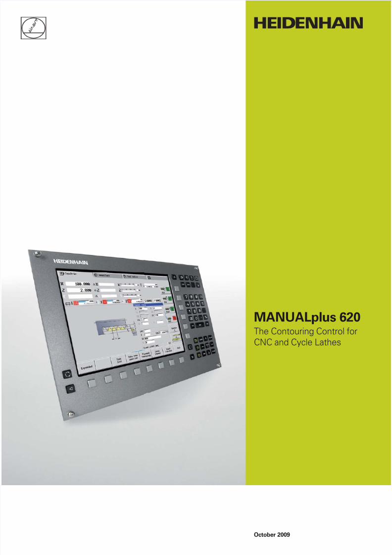
MANUALplus 620The Contouring Control for
CNC and Cycle Lathes
October 2009

8/3/2019 634_865-22
http://slidepdf.com/reader/full/634865-22 2/322
Start smart
For many years now, the MANUALplus has
been proving itself in daily use on cycle
lathes and has earned a reputation for
convenient manual machine operation.
Application-oriented cycle programming
enables the machinist to create and edit
programs rapidly and efficiently on the
lathe. The introduction of the
MANUALplus 620 extends the area ofapplication to single-spindle CNC lathes.
With the smart.Turn operating mode,
HEIDENHAIN has made yet another step
forward toward greater ease of use. Easily
understandable program entry in forms,
default setting for global values, numerous
selections and straightforward graphic
support ensure fast and easy operation.
The new smart.Turn interface is based on
the proven HEIDENHAIN-DIN PLUS,
because smart.Turn generates DIN PLUS
programs. It provides both the NC
programmer and the machine operator
with all relevant information during
program run.

8/3/2019 634_865-22
http://slidepdf.com/reader/full/634865-22 3/323
Contents
The MANUALplus 620...
Where can it be used? Compact and Versatile– MANUALplus 620, the control for CNC and cycle lathes
4
How does it look? Well Designed and User Friendly
– The MANUALplus 620 in dialog with the user
6
What can it do? Universally Applicable– The right programming mode for every task
8
Easy Machining with Cycles– Preprogrammed machining steps
– From single parts to series
10
Turning, Drilling and Milling in One Setup– Machining with the C axis
14
Well Thought Out, Simple and Flexible
– smart.Turn, the new method of NC programming (option)
16
Describing and Importing Contours– ICP interactive contour programming
18
Realistic Testing before Machining– Graphic simulation
20
Fast Availability of Tool Data and Cutting Data– MANUALplus tool database and technology database
22
Open for Communication– Fast data transfer with the MANUALplus 620
– DataPilot MP 620 programming station
24
... At a glance Overview– User functions
– Accessories
– Specifications
– Options
26

8/3/2019 634_865-22
http://slidepdf.com/reader/full/634865-22 4/324
Compact and Versatile– MANUALplus 620, The Control for CNC and Cycle Lathes
Thanks to its flexible design and numerous
programming features, MANUALplus 620
always gives you optimum support.
Regardless of whether you are manufac-
turing single parts or batches, simple or
complex workpieces, the control always
adapts to the needs of your company. The
MANUALplus 620 is characterized by its
simple operation and programming. It isquickly learned and requires minimum
training time.
The MANUALplus 620 was conceived both
for CNC and cycle lathes. It is suitable for
horizontal and vertical lathes. The
MANUALplus supports lathes with simple
tool holders and lathes with tool turrets.
The tool carrier of horizontal lathes can be
located in front of or behind the workpiece.
The MANUALplus supports lathes withspindle, one slide (X and Z axis), C axis or
positionable spindle, driven tools and
machines with a Y axis.
MANUALplus 620for cycle lathesOn the MANUALplus 620, rework or
simple tasks can be done in the same way
as on a conventional lathe. You move the
axes in the normal manner by turning the
handwheels. For difficult cuts like tapers,
undercuts or threads, the cycles of the
MANUALplus are available.
For small and medium-size production
runs, cycle programming will increase your
revenue. When machining the first
workpiece, you can store the machining
cycles, and already save valuable time
when machining the second workpiece.
For increased requirements and complex
machining tasks, you will profit from the
new programming mode smart.Turn.
MANUALplus 620 on a cycle lathe

8/3/2019 634_865-22
http://slidepdf.com/reader/full/634865-22 5/325
MANUALplus 620for CNC lathesRegardless of whether you are turning
simple parts or complex workpieces, the
MANUALplus 620 provides you with the
benefits of graphical contour input and
convenient programming with smart.Turn.
Programming with variables, controllingspecial machine components, or using
externally created programs, etc. is no
problem: simply switch to DIN PLUS. This
programming mode helps you solve all
your special tasks.
MANUALplus 620 on a CNC lathe

8/3/2019 634_865-22
http://slidepdf.com/reader/full/634865-22 6/326
Well Designed and User Friendly– The MANUALplus 620 in Dialog with the User
The screenThe TFT 12.1 inch color flat-panel display,
shows a clear overview of all relevant
information for programming, operating
and monitoring the machine tool and
control: program blocks, messages, error
messages, etc.
During program input the requiredparameters are illustrated in help graphics,
and during test run the MANUALplus
simulates the cutting process on the
screen. During program run the screen
displays information on the tool position,
the rotational speed, the feed rate and the
utilization of the drives as well as further
information on the machine status.
The positions of the tool are shown in large
characters. The respective distance-to-go,
the feed rate, the spindle speed and the
ID number of the current tool are also clearly
visible. A moving-bar diagram shows thecurrent utilization of the spindle and the
axis drives.
The keyboardThe MANUALplus needs very few keys.
Easily understood symbols clearly indicate
the functions.
The keys on the numeric keypad are used
both for data input and for selecting the
functions. The menu window displays the
available functions graphically. The function
keys below the screen are used to modifythe selected functions, assume position
and technology values, and control the data
input.
The machine control panelThe machine operating panel is designed
by the machine tool builder. Your machine
panel might look like this: handwheels for
saddle and cross slide, joystick for
continuous axis movement, rotary switch
for the handwheel transmission ratio,
rotary switch for spindle CCW/CW/stop,
buttons for cycle start/stop and anemergency stop switch.
PLC function keys for machine components
Unambiguous function keys for NC programming
Straightforward input forms for cycle programming, smart.Turn
programming or DIN PLUS programming. The input parameters
are illustrated in help graphics during NC programming.
Display of the machine status. The display is configurable.
You can choose a suitable function for each of the 16 segments,
and save different display assignments for the automatic and
manual mode.
Modes of operation

8/3/2019 634_865-22
http://slidepdf.com/reader/full/634865-22 7/327
Operating mode keys
Machine operating modes
Programming modes
Tables for tool data and
technology data
Parameters, file management,
transfer, diagnostics
Navigation keys
Previous/next group
Switch to the next detail
input form
Special keys
Activate special functions, such as
input options or input of characters
as on a cell phone
Calculator
Call up messages and errors
Screen/page up/down
Go to beginning of program/
list or to end of program/list
Clear error from machineoperating modes
Switch the help graphics between
outside/inside machining (cycle
programming)
smart keys

8/3/2019 634_865-22
http://slidepdf.com/reader/full/634865-22 8/328
±
±
±
±
±±
±
Machining with cycles
Finished cycle program
Machining with cycles
Define the cycle
Simulate the cycle
Machine the workpiece
Define the cycle
Simulate the cycle
Machine the workpiece
Save the cycle
Universally Applicable– The Right Programming Mode for Every Task
With its different programming operating
modes, cycle programming, smart.Turn
and DIN PLUS, the MANUALplus 620
always gives you optimum support for your
tasks.
Manual
Simple, non-repetitive machining tasks•Rework•
Thread repair•
Teach-in
Manual-oriented machining of small and•medium-size production runs
Graphic description of complex contours•
Regardless of whether you want to rework a
workpiece or machine a single part on a cycle
lathe, the cycles of the MANUALplus 620
will simplify your work. For manufacturing
batches, you create a cycle program by
saving the cycles during the machining of
the first workpiece. The effective
programming mode smart.Turn for fast and
easy NC program creation helps you take
care of more demanding tasks.

8/3/2019 634_865-22
http://slidepdf.com/reader/full/634865-22 9/329
±
±
±
± ± ±
Finished DIN program
DIN PLUS
External programming
Resolve a smart.Turn unit
Edit the DIN program
Simulate the DIN program
On CNC lathes, the best method to create
a program is to use smart.Turn. This
programming mode from HEIDENHAIN is
based on input forms and allows you to
create structured, easy-to-read NC
smart.Turn
Convenient smart.Turn programming•Graphic contour description•
Numerous machining units•
Special units•
Compatible with cycle programs•
DIN PLUS
Familiar G-code programming•Graphic contour description•
Numerous fixed cycles•
Variable programming and subprograms•
Resolving smart.Turn units into G-code•
commands
Compatible with externally created DIN•
programs
programs in which you can even store all
setup information needed to machine the
workpiece.
If you want to use the variable
programming feature or externally created
NC programs, or if you have to cope with
special requirements, DIN PLUS will give
you optimum support.
smart.Turn
Create smart.Turn program
Simulate smart.Turn program
Finished smart.Turn program

8/3/2019 634_865-22
http://slidepdf.com/reader/full/634865-22 10/3210
Easy Machining with Cycles (Option)– Preprogrammed Machining Steps
On the MANUALplus 620, you can use the
handwheel to perform simple operations,
such as turning or facing, just like on any
conventional lathe. Standard machining
operations, such as area clearance, slot
milling, recess turning, undercutting,
parting, thread cutting, boring, drilling, and
milling are stored in the MANUALplus 620
as cycles. You simply enter the positions,dimensions and specifications, and the
control will automatically run the machining
program.
Manual workpiece machiningThe MANUALplus 620 simplifies manual
turning with numerous functions, without
requiring you to learn complicated proce-
dures. This enables you, for example, to
adjust the feed rate and spindle speed
steplessly during machining, to machine
with preset tools or to part with constant
cutting speed during machining.
Workpiece machining with cyclesFor simple, non-recurring tasks, reworking,
thread repair or small production runs, the
cycles of the MANUALplus simplify your
work.
The programming graphics illustrate the
few entries needed for the cycles. Before
cutting, use the simulation to assure
yourself that the machining will run as
planned.
Thread cutting—three times faster with a cycle
Turn cylinders manuallyYou work as usual with the handwheels and the position display
on the screen.
Turn tapers automaticallyJust enter the dimensions—the MANUALplus 620 moves the
saddle and cross-slide automatically.

8/3/2019 634_865-22
http://slidepdf.com/reader/full/634865-22 11/3211
Fewer calculationsThe MANUALplus automatically calculates
the number of cuts for roughing, recessing,
recess turning or thread cutting, and for
pecking it determines the required number
of infeeds. When turning a taper, you can
enter either the starting point and end
point, or the starting point and the taper
angle—whichever is shown on yourdrawing.
Constant availability of tool dataThe MANUALplus uses a tool database.
Tool data, such as cutting radius, tool angle
and point angle only have to be entered
once. The tool-setting dimensions can be
measured by touching the workpiece with
a tool. The MANUALplus saves the data.
The next time you use the tool, you simply
call the tool number. The MANUALplus
automatically adjusts for the correct tool
size. You can immediately work to
dimension.
When you turn a contour, the MANUALplus
automatically compensates the tool edge
cutting radius to increase the dimensional
accuracy of your workpiece.
Technology data as default valuesThe MANUALplus saves the cutting data
according to the criteria of workpiece
material, tool material and machining
mode. As you have already entered the
cutting material in the tool definition, you
need only enter the material of your
workpiece. This provides the cycle with all
data required for setting default values forthe cutting data.
Reference pointsYou can define the workpiece datum by
touching the workpiece with the tool or by
entering the datum coordinates.
Approach the tool-change point once and
store this position. After that, a simple
cycle call suffices to traverse to the tool-
change point again.
Protective zone for the spindle
For every tool movement in the negativeZ direction, the MANUALplus checks
whether the programmed protective zone
would be violated. If so, it stops the
movement and responds with an error
message.
Run a cycle to cut a thread automaticallyCall the appropriate fixed cycle and enter the dimensions.
The MANUALplus 620 performs the operation automatically.

8/3/2019 634_865-22
http://slidepdf.com/reader/full/634865-22 12/3212
Easy Machining with Cycles (Option)– From Single Parts to Series
The first workpieceYou machine the workpiece cycle-by-cycle,
as always, and store the machining steps.
When you have finished machining, you
save the created cycle program, creating
the working plan for the workpiece. The
MANUALplus displays the individual
machining steps in the proper sequence
on the screen.
Repeating individual cyclesAfter you have saved the cycles for one
part you can always go back later to edit or
delete the steps used to machine it, or
insert new steps.
You can save a great deal of time with the
MANUALplus when using this feature to
produce a family of parts.
Saving your work for the next partYou can store all cycles and rerun them
automatically. Each additional part
machined saves you time and cost.
1. Transverse turning 2. Longitudinal turning

8/3/2019 634_865-22
http://slidepdf.com/reader/full/634865-22 13/3213
3. Finishing 4. Threading with
undercut and chamfer
Cycles for turningYou will always find the appropriate cycle
in the cycle menus of the MANUALplus.
The corresponding graphic explains the
operation, all required dimensions and
other entries. After entering these values,
you can graphically inspect the cutting
process and let the operation run
automatically.
Area clearance – cutting and finishing
Longitudinal/transverse cutting for simple
contours
Longitudinal/transverse cutting with
plunging
Recessing and recess turning – cutting and finishing
Radial/axial recessing for simple contours
Longitudinal/transverse recess turning
for simple contours
Threads and undercuts
Single- or multi-start longitudinal,
tapered or API thread
Undercuts as per DIN 76,
DIN 509 E and DIN 509 F
Undercut form H, form K or
form U
Parting
Undercuts and parting
Radial/axial ICP recessing for any
contours
Longitudinal/transverse ICP recess
turning for any contours
Longitudinal/transverse ICP cutting for
any contours
Longitudinal/transverse ICP contour
parallel cutting

8/3/2019 634_865-22
http://slidepdf.com/reader/full/634865-22 14/3214
Turning, Drilling and Milling in One Setup– Machining with the C Axis and Y Axis (Option)
Cycles for drilling
Axial/radial drilling
Axial/radial pecking
Axial/radial tapping
Axial thread milling
You can use the MANUALplus 620 to drill
and mill your workpiece on the end face
and lateral surface in one setup. This can
be done by expanding the control to
include C-axis or Y-axis machining and
driven tools.
C axis or positionable spindle*
A driven tool as well as a C axis orpositionable spindle are necessary for
milling or drilling operations that must be
carried out off-center on the end face or
lateral surface.
Y axis*With the Y-axis option of the
MANUALplus 620 you can machine slots
or pockets with plane bottoms and
perpendicular slot edges. By defining the
spindle angle, you can determine the
position of the milling contours on the
workpiece. For programming and
verification of these operations, theworkpiece is shown in side and face view.
The Y axis is supported in the smart.Turn
and DIN programming feature.
*The machine and the MANUALplus 620 must be
adapted to this function by the machine tool builder.
Drilling or tappingYou enter the depth of the hole and, if required, the pecking depth
for chip breaking. For tapping with a floating tap holder you also
enter the pitch—and you’re finished!
Drilling and peckingThe MANUALplus drills and pecks
individual holes on the end face and lateral
surface. Via parameters you can easily
program infeed reductions for the
beginning of drilling or when drilling
completely through the workpiece.
TappingTapping cycles are available for the end
face and lateral surface.
Drilling and milling patternsIf bore holes, slots or ICP milling cycles are
located at regular distances on a straight
line or a circular arc, the MANUALplus
greatly simplifies your work: You can create
these patterns on the end face or lateral
surface with just a few key strokes.
Thread millingOn lathes equipped with a C axis, you can
take advantage of the thread-milling tools.The MANUALplus supports axial thread
milling.

8/3/2019 634_865-22
http://slidepdf.com/reader/full/634865-22 15/3215
Milling slots and simple figuresSlot milling with the MANUALplus is very
simple. You define the position and depth
of the slot as well as the cutting values—
the milling cycles automatically take care of
the rest.
Even for simple contours such as circles,
rectangles and equilateral polygons, just afew keystrokes are necessary to determine
the figure and position on the end face or
lateral surface.
Contour and pocket millingThe milling cycles of the MANUALplus
support contour and pocket milling. You
determine all the important details, such as
machining direction, milling direction,
approach and departure behavior, feed
rates, etc. The MANUALplus automatically
compensates for the tool radius.
You can mill the pocket in two stages—firstroughing, then finishing. The result is high
accuracy and good surface quality.
In smart.Turn and DIN programming, the
MANUALplus 620 supports various infeed
strategies. You can choose between direct,
reciprocating or helical infeed, or infeed at
the predrilling position.
Cycles for milling
Axial/radial slot milling
Axial/radial figure milling (circles,
rectangles, regular polygons)
Axial/radial ICP contour milling
Face milling (single surfaces,
flattening, polygon)
Helical slot millingFace and lateral-surface millingContours such as slots and simple figures can be machined with
standard milling cycles—complex contours are defined using ICP
and are then machined using ICP milling cycles.
Face millingThe face milling cycle machines individual
surfaces, equilateral polygons or a circle—
even off-center.
Helical slot millingThe helical-slot milling cycle is useful for
machining lubrication grooves. You
determine all important parameters, suchas pitch, milling in multiple infeeds, etc.

8/3/2019 634_865-22
http://slidepdf.com/reader/full/634865-22 16/3216
Has the safety clearance been correctly
entered, is the speed limit taken into
account, how are oversizes defined? All
this needs to be considered not only by the
beginner, but also by the experienced NC
programmer when creating conventional
DIN programs.
The smart.Turn principleThe working block—called a unit—plays
the central role in smart.Turn programs. A
unit describes a machining step completely
and unambiguously. The unit includes the
tool call, the technology data, the cycle call,
the approach and departure strategies as
well as global data, such as safety
clearance, etc. All these parameters are
summarized in one, clearly structured
dialog box.
The smart.Turn principle gives you the
reassurance that the working block is
defined correctly and completely. In the NCprogram, smart.Turn lists the DIN PLUS
commands of the unit. This gives you an
overview of all working-block details at any
time.
Well Thought Out, Simple and Flexible– Simple Programming with smart.Turn (Option)
Programming made simpleWith smart.Turn, you program with the aid
of easy-to-use, unambiguous fillable forms.
The overview form shows you a summary
of the selected unit, and subforms provide
information on the details of a working
block. Clearly arranged help graphics
illustrate all required input. If input options
are available, smart.Turn displays a list ofthe available options for selection.
Global program parameters, such as
oversizes, safety clearances, coolants, etc.,
are defined once in the start unit. Then
smart.Turn transfers these parameters to
the other units.
smart.Turn supports units for roughing,
finishing, recessing, recess turning, thread
cutting, boring, drilling, tapping, and milling,
as well as special units for program start,
program end, moving the C axis in/out,
subprograms and program-section repeats.
By the way: You need not stop the
manufacturing process for programming
with smart.Turn. You can create and test
the smart.Turn program while the program
is running.
Structured and easy-to-readClearly structured and easy-to-read—these
are the characteristics of smart.Turn
programs. It uses section codes that
clearly distinguish between the program
head with setup information, the turret
assignment, the workpiece description and
the actual machining operation.
The smart.Turn technique not only ensures
that the program is easy to read, but it also
makes it possible to save all information
required for producing the workpiece in the
NC program.

8/3/2019 634_865-22
http://slidepdf.com/reader/full/634865-22 17/3217
Programming contourssmart.Turn enables you to work simply and
flexibly. Simple contours can be defined
with just a few entries in the cycle. Complex
contours are described with ICP interactive
graphics. Workpiece descriptions that are
available in DXF format can be easily
imported.
Contour follow-upWhen you define the workpiece blank,
smart.Turn uses the contour follow-up
function, by which the MANUALplus
computes the new blank form after each
cut. The machining cycles are adapted
automatically to the current workpiece
blank. They are so intelligent that they avoid
air cuts and to optimize approach paths,
even if the workpiece material has been
previously removed.
Technology data as default values
The MANUALplus saves the cutting dataaccording to the criteria of workpiece
material, tool material and machining
mode. As you have already entered the
cutting material in the tool definition, you
need only enter the material of your
workpiece. This provides smart.Turn with
all data for setting default values for the
cutting data.
Programming in DIN PLUSsmart.Turn offers units for all machining
tasks as well as units for special functions.
If you want to control special machine
components, or use the variable
programming function or other complex
functions that are not provided by smart.
Turn, DIN PLUS will support you. Itprovides powerful machining cycles,
program branches and programming with
variables.
The MANUALplus 620 also enables you to
switch back and forth between the smart.
Turn and DIN PLUS programming modes
within a program.
Because the units are based on DIN PLUS,
you can break up a unit into blocks at any
time to modify and optimize the resulting
DIN PLUS program section.
Of course the MANUALplus 620 also
allows you to create a “real” DIN program,
or to import and use externally created
programs.

8/3/2019 634_865-22
http://slidepdf.com/reader/full/634865-22 18/3218
For jobs that cannot be machined with the
standard cycles because of the complexity
of the workpiece or the lack of certain
dimensions in the workpiece drawing, you
need ICP, the interactive contour program-
ming. You describe the contour elements
directly as they appear in the workpiece
drawing. Or you simply import the contour
directly if the drawing is available inDXF-format.
Contour programming with ICPYou define an ICP contour in the graphic
editor by entering the contour elements
step-by-step. When selecting the contour
elements, you already specify the direction
of the line or the direction of rotation of the
circular arc. This way the MANUALplus
needs very little information about the
contour element.
When entering the data, you decide
whether the coordinates are absolute orincremental, and whether you enter the
end point or the length of the line or the
center point or the radius of a circular arc.
You also specify whether the path to the
next contour element should be tangential
or non-tangential.
As long as they are mathematically
defined, the MANUALplus calculates
missing coordinates, intersections, center
points, etc. If there are multiple solutions,
you can select the desired solution from
the mathematically possible variants
displayed. You can modify or changeexisting contours.
Describing and Importing Contours– ICP Interactive Contour Programming (Option)
Superimposing form elementsThe ICP editor recognizes the chamfer,
rounding and undercut (DIN 76, DIN 509 E,
DIN 509 F, etc.) form elements. You can
enter these form elements in the course of
the sequential contour definition. However,
it is often easier to first define the “rough”
contour, and then to superimpose the form
elements. Select the contour corner onwhich the form element is to be placed,
then insert the element.
ICP contours for cycle programsIn turning or milling operations, standard
contours are defined in the cycle. Complex
contours are described with ICP and then
called in an ICP roughing, ICP recessing,
ICP recess turning or ICP milling cycle.
The ICP editor can be called directly during
cycle programming.
ICP contours for smart.Turn andDIN PLUSIn smart.Turn you have various possibilities
for describing the contour to be machined.
You can describe simple contours right in
the unit and use ICP for turning or milling
contours as well as linear or circular drilling
and milling patterns. The contour defined
with ICP is transferred to the smart.Turnprogram. In the unit you enter a reference
to the contour section to be machined.
If you are working in DIN PLUS mode, you
can also describe the turning and milling
contours, linear and circular patterns with
ICP. In the contour-based cycles you enter a
reference to the contour section to be
machined.
The ICP editor can be called immediately
from within smart.Turn.

8/3/2019 634_865-22
http://slidepdf.com/reader/full/634865-22 19/3219
0
¬ 4
8
¬ 6
3
4 5 °
R 1 2 DIN 76-A
2 x 45°
M 2 0 x 1 . 5
3
0.5 x 45°0.5 x 45°
39
10°
¬ 5
3
¬ 5
2
¬ 7
0
4 0 °
3 5 °
1 8
4 2
. 5
3 6
. 5 5 6
6 2
7 9
. 5
1 0 0
DXF import of contours (option)Why should you painstakingly enter
contour elements if the data already exists
in the CAD system? ICP makes it possible
to import contours in DXF format directly
into the MANUALplus 620. Not only does
this save time otherwise spent on pro-
gramming and testing, but you can also be
sure that the finished contour is exactlyaccording to the designer’s specifications.
DXF contours can describe workpiece
blanks, finished parts, contour trains and
milling contours. They must exist as two-
dimensional elements in a separate layer,
i.e. without dimension lines, wrap-around
edges, etc.
First, you download the DXF file onto the
MANUALplus over the network or use a
USB stick. Since the DXF format is
fundamentally different from the ICP
format, the contour is converted from DXF
to ICP format during the import. Thiscontour is then treated as a normal ICP
contour, and is available for smart.Turn,
DIN PLUS or cycle programming.

8/3/2019 634_865-22
http://slidepdf.com/reader/full/634865-22 20/3220
Timely detection of errors is very important
for the production or repair of single parts.
With its graphic simulation feature, the
MANUALplus 620 supports you in
checking the program for errors—exactly
and with the real dimensions of the
contour and cutting edge.
Graphic simulationBefore actual machining, you use the
graphic simulation to inspect the
machining sequence,•
proportioning of cuts,•
resulting contour.•
In the graphic simulation you can display
the tool cutting edge. You see the cutting-
edge radius, the cutting-edge width and
the cutting-edge position with their actual
dimensions. This helps to recognize
machining details or collision risks in time.
Wire-frame or cutting-path graphics,machining simulationThe MANUALplus supports various views
of the tool paths and the machining process.
You can choose the type of verification
best suited to the tool or machining
process used.
Realistic Testing before Machining– Graphic Simulation
The wire frame graphics is particularly
convenient if you only need a quick
overview of the proportioning of cuts. The
path of the theoretical tool tip, however, is
not identical with the contour of the
workpiece. This view is therefore not as
suitable if you wish to run a thorough check
of the machined contour.
A more accurate contour verification is
provided by the cutting-path graphics.
The cutting path graphics account for
the exact geometry of the tool tip. You
immediately see if material was left
behind, the contour is damaged or the
overlaps are too large. The cutting path
graphics is especially useful for recessing,
drilling and milling operations where the
tool shape has an essential influence on
the accuracy of the resulting workpiece.
The machining simulation (material
removal graphic) displays the workpieceblank from which material is removed.
The blank is displayed as a white surface.
The MANUALplus simulates every tool
movement at the programmed cutting
speed and removes the material.

8/3/2019 634_865-22
http://slidepdf.com/reader/full/634865-22 21/3221
Calculating the machining timeIf your customer needs an offer in a hurry,
and you need exact information in a very
short time, the MANUALplus is a valuable
aid with its machining time calculator.
During simulation of the cycle, smart.Turn
or DIN PLUS program, the MANUALplus
calculates the time per piece for the
programmed machining.
Along with the total time, the table displays
the machining time and idle time of each
cycle or each tool insert. This assists you
not only in your calculations, but you can
also tell at a glance whether there are
more possibilities for optimization during
the machining process.
Selecting viewsIf your lathe is equipped with driven tools
and positionable spindle, a C axis or a Y
axis, the MANUALplus also simulates
machining on the end face and lateral
surface, or the XY and YZ plane. You select
the combination of windows best suited to
the job. This gives you everything you need
to closely examine your drilling and millingoperations.
The MANUALplus depicts C-axis machining
of the cylindrical surface as an “unrolled”
plane surface.
Zoom functionUse the “magnifying glass” to set the view
to your current needs: greatly magnified in
order to control the machining details, or
zoomed-out to show the entire workpiece
or current working space in order to get an
overview of the machining process.

8/3/2019 634_865-22
http://slidepdf.com/reader/full/634865-22 22/3222
Tool databaseThe MANUALplus can store 250 tools in
the standard tool database. The tool
database can be expanded to 999 tools
(option).
The MANUALplus differentiates between
various types of turning, drilling and milling
tools. The required data input variesdepending on the tool type. This ensures
that all important parameters are included
even though data input has been reduced.
You enter the tool parameters, such as the
cutting radius, tool angle, point angle,
cutting material, and the tool description in
conversational mode. The input parameters
are illustrated in context-sensitive help
graphics.
Tool listThe MANUALplus presents all tool data in
the tool list in a clearly structured manner.Different sorting criteria help to find the
desired tool quickly.
This list not only gives you an instant
overview of your tools, it also is the basis
for transferring tool data when creating NC
programs or during manual machining
tasks.
Fast Availability of Tool Data and Cutting Data– MANUALplus Tool Database and Technology Database
Wear compensationThe MANUALplus offers a simple and
straightforward function for compensating
tool wear in both the X and the Z axes. You
may enter the compensation values during
machining or after machining the
workpiece.
Tool measurementThe MANUALplus 620 offers various
possibilities for the measurement of tools
directly on the machine:
By touching the workpiece•
By means of an optical gauge* (option).•
The tool is manually traversed to the
cross hairs of the measuring optics, and
the value is saved with a keystroke.
By using a tool touch probe* (option).•
The tool moves in the direction of
measurement. When the tool touch
probe signal is triggered (e.g. from the
TT 140 touch trigger probe with a cuboid
probing element), the setting dimensionis determined and saved.
Using an optical gauge or a tool touch
probe for the measurement of tools gives
you the tool data quickly, reliably and
accurately.
*The machine and MANUALplus 620 must be adapted
to this function by the machine tool builder.

8/3/2019 634_865-22
http://slidepdf.com/reader/full/634865-22 23/3223
Turret assignmentIf your lathe is equipped with a tool turret,
you can view the programmed turret
assignment at any time. The MANUALplus
displays all important tool parameters.
If you want to change the tool assignment
or the tools in the turret, you can additionally
display the entries of the tool database inthe lower window. Now you need only
select the desired turret pocket and choose
the correct tool from the database. You can
transfer the tool data to the turret assignment
entry with a simple keystroke.
Technology data (option)With the MANUALplus 620 you need enter
the cutting data only once. The control
saves the cutting data according to the
criteria of workpiece material, cutting
material, machining mode. Thanks to this
three-dimensional table, the control always
knows the correct feed rate and the correct
cutting speed.
The MANUALplus 620 determines the
machining mode from the cycle or the unit.
The cutting material is defined in the tool
description. You need only define the
workpiece material at the beginning of the
cycle program or the smart.Turn program,
and the MANUALplus will propose the
correct values for your machining
operation. You can use the suggested
cutting parameters or adjust them if
required.
In its standard version, you can store thecutting data for 9 workpiece-material/tool-
material combinations in the technology
database of the MANUALplus. It can be
expanded to 62 combinations (option*).
Each workpiece-material/tool-material
combination includes the cutting speed,
the main and secondary feed rates, and
the infeed for 16 machining modes.

8/3/2019 634_865-22
http://slidepdf.com/reader/full/634865-22 24/3224
Open for Communication– Fast Data Transfer with the MANUALplus 620
The networked MANUALplus 620The MANUALplus 620 can be integrated
into networks and connected with PCs,
programming stations and other data
storage devices. Even in its standard
version, the MANUALplus features a latest-
generation Fast Ethernet interface. The
MANUALplus communicates with NFS
servers and Windows networks in TCP/IPprotocol without needing additional
software. The fast data transfer at rates of
up to 100 Mbps guarantees very short
transfer times.
USB interfaceThe MANUALplus 620 supports standard
memory media with USB interface. Using
USB memory media (such as memory
sticks), you can quickly and easily exchange
DXF contours, ICP contour descriptions,
NC programs, tool parameters, etc.,
between systems that are not connected
to each other.
All programs at a glanceAfter entering the path of the partner
terminal, your own programs will be listed
on the left side of the screen, and your
partner’s programs are on the right side.
Now select the programs that you want to
transfer and press the send or receive
button. The data is transferred reliably and
almost instantaneously.
Transferring programsThe easiest and most convenient method
of transferring data is to integrate the
systems into your company network.
When transferring NC programs, the
MANUALplus even considers the files
related to the cycle program, smart.Turn
program or DIN PLUS program, such as
contour descriptions, DIN macros or
subprograms.
Exchanging tool dataOnce you have acquired tool data you may
also transfer them. This is not only important
for data backup, but is also useful when
using the DataPilot programming station
for PCs. Advantages include consistently
current data and not having to acquire the
same data twice.
Programs for data transferWith the aid of the free PC program
TNCremoNT from HEIDENHAIN and an
Ethernet or other data interface you can
transfer remotely stored part programs•
and tool or pallet tables in both directions
and
make backups.•
With the powerful TNCremoPlus software
you can also transfer the screen contents
of the control to your PC by means of the
live-screen function.
Company network
CAD/CAMsystem
DataPilot MP 620Ethernetinterface
iTNC 530Ethernetinterface
TNC 320Ethernet
interface
MANUALplus 620Ethernetinterface

8/3/2019 634_865-22
http://slidepdf.com/reader/full/634865-22 25/3225
DataPilot MP 620 is the PC programming
station for the MANUALplus 620 and the
organizing system for the workshop and
design office. By shifting the programming,
program testing, and program optimization
to the PC, machine idle times are greatly
reduced.
That is why DataPilot MP 620 is the idealsupplement to the MANUALplus 620 for
program creation, archiving, and apprentice
and advanced training.
Creating programsProgramming, testing and optimizing cycle
programs, smart.Turn programs and
DIN PLUS programs with DataPilot on your
PC substantially reduce idle machine
times. You do not need to adjust your way
of thinking, since you program and test
with DataPilot in exactly the same way as
on the lathe. DataPilot has the samesoftware as the control. This ensures that a
program created with DataPilot can be run
on the machine immediately.
Archiving programsEven though the MANUALplus has a
nearly inexhaustible memory capacity, you
should also back up your programs on an
external system. The MANUALplus
features a USB and an Ethernet interface.
This enables you to integrate the
MANUALplus into your existing network or
to connect the DataPilot PC directly to the
control.
Convenient program-transfer functions
support both programming and archiving
on the DataPilot PC.
– The DataPilot MP 620 Programming Station
Training with DataPilot MP 620Because DataPilot MP 620 is based on the
same software as the MANUALplus 620, it
is ideally suited for apprentice and advanced
training. Programming and program testing
on the DataPilot PC function exactly the
same as they do on the machine. Even
setup functions such as workpiece datum
definition, tool measurement or machining of
individual cycles, cycle programs, smart.Turn
or DIN PLUS programs are simulated with
DataPilot. This gives the trainee the
experience needed to enable him to safely
operate the machine later.
System requirementsDataPilot runs on PCs with the Windows XP
or Windows Vista operating systems.

8/3/2019 634_865-22
http://slidepdf.com/reader/full/634865-22 26/3226
Overview– User Functions
User functions
S t a n d a r d
O p t i o
n
Configuration •
•
0-2
55+0-2
70+0-2
94+0-2
Basic version: X and Z axis, spindle
Positionable spindle and driven tool
C axis and driven tool
Y axis
W axis (as closed loop PLC axis)
Digital current and speed control
Operating modesManual operation •
•
11
Manual slide movement through manual direction keys, intermediate switch or electronic
handwheels
Graphic support for entering and running cycles without saving the machining steps in
alternation with manual machine operationThread reworking (thread repair in a second workpiece setup)
Teach-in mode 8 Sequential linking of fixed cycles, where each cycle is run immediately after input, or is
graphically simulated and subsequently saved.
Program run
•
9
8
All are possible in single-block and full-sequence modes
DIN PLUS programs
smart.Turn programs
Cycle programs
Setup functions •
•
•
•
17
17
Workpiece datum setting
Definition of tool-change position
Definition of protection zone
Tool measurement by touching the workpieceTool measurement with a tool touch probe
Tool measurement with an optical gauge
ProgrammingCycle programming
8
8
8
8
8
8
8
8+55
8+55
8+55
8+55
8+55
8
8
8
8+9
Area clearance cycles for simple and complex contours, and contours described with ICP
Contour-parallel area clearance cycles
Recessing cycles for simple or complex contours, or contours defined with ICP
Repetitions with recessing cycles
Recess turning cycles for simple and complex contours, and contours described with ICP
Undercut and parting cycles
Threading cycles for single or multi-start longitudinal, taper or API threads
Cycles for axial and radial drilling, pecking and tapping operations with the C axis
Thread milling with the C axis
Axial and radial milling cycles for slots, figures, single surfaces and polygons as well as for
complex contours defined with ICP for machining with the C axisHelical slot milling with the C axis
Linear and circular patterns for drilling and milling operations with the C axis
Context-sensitive help graphics
Transfer of cutting values from technology database
Use of DIN macros in cycle programs
Conversion of cycle programs to smart.Turn programs
Interactive Contour
Programming (ICP)
8/9
8/9
8/9
8/9
8/9
8/9
8/9
Contour definition with linear and circular contour elements
Immediate display of entered contour elements
Calculation of missing coordinates, intersections, etc.
Graphic display of all solutions for selection by the user if more than one solution is possible
Chamfers, rounding arcs and undercuts available as form elements
Input of form elements immediately during contour creation or by superimposition later
Changes to existing contours can be programmed

8/3/2019 634_865-22
http://slidepdf.com/reader/full/634865-22 27/3227
User functions
S t a n d a r d
O p t i o
n
ICP (continued) 8/9+55
9+70
8/9+42
C-axis machining on face and lateral surface:
Description of individual holes and hole patterns (only in smart.Turn)
Description of figures and figure patterns for milling (only in smart.Turn)
Creation of freely definable milling contours
Y-axis machining on the XY and ZY planes (only in smart.Turn):
Description of individual holes and hole patterns
Description of figures and figure patterns for milling
Creation of freely definable milling contours
DXF import: Import of contours for lathe and milling operations
smart.Turn
programming
9
9
9
9
9
9
9
9
9+55/70
9+55
9
9
9
9
The basis is the unit, which is the complete description of a machining block (geometry,
technology and cycle data)Dialog boxes divided into overview and detail forms
Fast navigation between the fillable forms and input groups via the “smart” keys
Context-sensitive help graphics
Start unit with global settings
Transfer of global values from the start unit
Transfer of cutting values from technology database
Units for all turning and recessing operations for simple contours and ICP contours
Units for boring, drilling and milling operations with the C and Y axis for simple holes, milling
contours and drilling and milling patterns or those programmed with ICP
Special units for activating/deactivating the C axis, subprograms and section repeats
Verification graphics for blank and finished part and for C and Y axis contours
Turret assignment and other setup information in the smart.Turn program
Parallel programming
Parallel simulation
DIN PLUS
programming
•
•
•
•
•
•
•
•
••
55
70
8/9
9
Programming in DIN 66025 format
Extended command format (IF... THEN ... ELSE...)
Simple geometry programming (calculation of missing data)
Powerful machining cycles for area clearance, recessing, recess turning and thread machining
Powerful machining cycles for boring, drilling and milling with the C axis
Powerful machining cycles for boring drilling and milling with the Y axis
Subroutines
Programming with variables
Contour description with ICP
Program verification graphics for workpiece blank and finished part
Turret assignment and other setup information in the DIN PLUS program
Conversion of smart.Turn units into DIN PLUS command sequences
Parallel programmingParallel simulation
Program verificationgraphics
•
•
•
•
•
•
•
Graphic simulation of the cycle process or of the cycle, smart.Turn or DIN PLUS program
Display of the tool paths as wire-frame or cutting-path graphics, special identification of the
rapid-traverse paths
Machining simulation (2-D material-removal graphic)
Side or face view, or 2-D view of cylindrical surface for verification of C-axis machining
Display of programmed contours
View of face and YZ plane for verification of Y-axis machining
Shifting and magnifying functions
Machining time analysis •
•
•
Calculation of machining time and idle machine time
Consideration of switching commands triggered by the CNC
Representation of times per individual cycle or per tool change

8/3/2019 634_865-22
http://slidepdf.com/reader/full/634865-22 28/3228
User functions
S t a n d a r d
O p t i o
n
Tool database •
•
•
•
•
•
•
10
10
10
For 250 tools
For 999 tools
Tool description can be entered for every tool
Automatic inspection of tool-tip position with respect to the contour
Compensation of tool-tip position in the X/Y/Z plane
Precision path correction via handwheel, transferring compensation values to the tool table
Automatic tool-tip and cutter radius compensation
Tool monitoring for lifetime of the insert (tool tip) or the number of workpieces produced
Tool monitoring with automatic tool change after tool insert wear
Management of multipoint tools (multiple inserts or reference points)
Technology database 8/9
8/9
8/9
8/9
10
Access to cutting data after definition of workpiece material, cutting material and machiningmode. The MANUALplus distinguishes between 16 machining modes. Each workpiece-
material/tool-material combination includes the cutting speed, the main and secondary feed
rates, and the infeed for 16 machining modes.
Automatic determination of the machining modes from the cycle or the machining unit
The cutting data are entered in the cycle or in the unit as default values
9 workpiece-material/tool-material combinations (144 entries)
62 workpiece-material/tool-material combinations (992 entries)
Conversational languages •
41
Chinese (simplified), Chinese (traditional), Czech, Danish, Dutch, English, Finnish, French,
German, Hungarian, Italian, Polish, Portuguese, Russian, Spanish, Swedish
For more conversational languages, see Option
Overview– User Functions (Continued)
– Accessories
Accessories
Electronic handwheels HR 180 • panel-mounted handwheels with connection to position inputs, plus
One• HR 130 panel-mounted serial handwheel, or one HR 410 portable serial handwheel
Tool calibration TT 140 touch trigger probe with cuboid probe contact
DataPilot MP 620 Control software for PCs for programming, archiving, and training for the MANUALplus 620
Full version with license for single station or multiple stations•
Demo version (free of charge)•

8/3/2019 634_865-22
http://slidepdf.com/reader/full/634865-22 29/3229
Overview– Specifications
Specifications
S t a n d a r d
Components •
•
•
MC 420 main computer
CC 422 controller unit
BFT 131 operating panel with 12.1-inch TFT color flat-panel display
Operating system • HEROS real-time operating system for machine control
Memory •
•
512 MB RAM for control applications
Hard disk with at least 13 GB program memory
Input resolution anddisplay step
•
•
•
X axis: 0.5 µm, diameter 1 µm
Z and Y axis: 1 µm
C axis: 0.001°
Interpolation •
•
•
Straight line: in 2 principal axes (max. ±100 m), optional in 3 principal axes
Circle: in 2 axes (radius max. 999 m), optional additional linear interpolation of the third axis
C axis: Interpolation in the linear axes X and Z with the C axis
Feed rate •
•
•
mm/min or mm/rev
Constant surface speed
Max. feed rate (60 000/pole pairs × ball screw pitch) at fPWM = 5000 Hz
Spindle Maximum 40 000 rpm (with 2 pole pairs)
Axis feedback control •
•
••
•
Digital drive control for synchronous and asynchronous motors
Position loop resolution: Signal period of the position encoder/1024
Position control clock pulse: 3 msSpeed control clock pulse: 0.6 ms
Current control: 0.1 ms
Error compensation •
•
Linear and nonlinear axis error, backlash, reversal spikes during circular movements
Stick-slip friction
Data interfaces •
•
100BaseT Fast Ethernet interface
2x USB 1.1
Diagnosis • Fast and simple troubleshooting through integrated diagnostic aids
Ambient temperature •
•
Operation: +5 °C to 45 °C
Storage: –35 °C to +65 °C

8/3/2019 634_865-22
http://slidepdf.com/reader/full/634865-22 30/3230
Overview– Options
Optionnumber
Option ID Remark
012
Additional axis 354 540-01
353 904-01
353 905-01
Additional control loops 1 to 3
8 Software option 1 632 226-01 Cycle programmingContour description with ICP•
Cycle programming•
Technology database with 9 workpiece-material/tool-material combinations•
9 Software option 2 632 227-01 smart.TurnContour description with ICP•
Programming with smart.Turn•Technology database with 9 workpiece-material/tool-material combinations•
10 Software option 3 632 228-01 Tools and technologyTool database expanded to 999 entries•
Technology database expanded to 62 workpiece-material/tool-material•
combinations
Support of multipoint tools•
Tool life monitoring with exchange tools•
11 Software option 4 632 229-01 ThreadsThread recutting•
Handwheel superimposition during thread cutting•
17 Software optionTCH PROBE functions
632 230-01 Tool measurementDetermining tool-setting dimensions with a tool touch probe•
Determining tool-setting dimensions with an optical gauge•
41 Additional language 530 184-01
530 184-02
530 184-03
530 184-04
530 184-06
530 184-07
530 184-08
530 184-09
530 184-10
Slovenian
Slovak
Latvian
Norwegian
Korean
Estonian
Turkish
Romanian
Lithuanian
42 DXF import softwareoption
632 231-01 DXF importLoading of DXF contours•
55 C-axis machining
software option
633 944-01 C-axis machining
70 Y-axis machining 661 881-01 Y-axis machining
94 W-axis machining 679 676-01 Support of W axis

8/3/2019 634_865-22
http://slidepdf.com/reader/full/634865-22 31/3231

8/3/2019 634_865-22
http://slidepdf.com/reader/full/634865-22 32/32
PH Machinebanks` CorporationQuezon City, Philippines 1113E-mail: [email protected]
PL APS02-489 Warszawa, Polandwww.apserwis.com.pl
PT FARRESA ELECTRÓNICA, LDA.4470 - 177 Maia, Portugalwww.farresa.pt
RO HEIDENHAIN Reprezentanta RomaniaBrasov, 500338, Romaniawww.heidenhain.ro
RS Serbia − BG
RU OOO HEIDENHAIN125315 Moscow, Russiawww.heidenhain.ru
SE HEIDENHAIN Scandinavia AB12739 Skärholmen, Swedenwww.heidenhain.se
SG HEIDENHAIN PACIFIC PTE LTD.Singapore 408593www.heidenhain.com.sg
SK KOPRETINA TN s.r.o.91101 Trencin, Slovakiawww.kopretina.sk
SL Posredništvo HEIDENHAINNAVO d.o.o.2000 Maribor, Sloveniawww.heidenhain-hubl.si
TH HEIDENHAIN (THAILAND) LTDBangkok 10250, Thailandwww.heidenhain.co.th
TR T&M Mühendislik San. ve Tic. LTD. STI·.
34728 Ümraniye-Istanbul, Turkeywww.heidenhain.com.tr
TW HEIDENHAIN Co., Ltd.Taichung 40768, Taiwan R.O.C.www.heidenhain.com.tw
UA Gertner Service GmbH Büro Kiev01133 Kiev, Ukrainewww.gertner.biz
US HEIDENHAIN CORPORATIONSchaumburg, IL 60173-5337, USAwww.heidenhain.com
VE Maquinaria Diekmann S.A.Caracas, 1040-A, VenezuelaE-mail: [email protected]
VN AMS Advanced ManufacturingSolutions Pte LtdHCM City, Viêt NamE-mail: [email protected]
ZA MAFEMA SALES SERVICES C.C.Midrand 1685, South Africawww.heidenhain.co.za
ES FARRESA ELECTRONICA S.A.08028 Barcelona, Spainwww.farresa.es
FI HEIDENHAIN Scandinavia AB02770 Espoo, Finlandwww.heidenhain.fi
FR HEIDENHAIN FRANCE sarl92310 Sèvres, Francewww.heidenhain.fr
GB HEIDENHAIN (G.B.) LimitedBurgess Hill RH15 9RD, United Kingdomwww.heidenhain.co.uk
GR MB Milionis Vassilis17341 Athens, Greece
www.heidenhain.grHK HEIDENHAIN LTD
Kowloon, Hong KongE-mail: [email protected]
HR Croatia − SL
HU HEIDENHAIN Kereskedelmi Képviselet1239 Budapest, Hungarywww.heidenhain.hu
ID PT Servitama Era ToolsindoJakarta 13930, IndonesiaE-mail: [email protected]
IL NEUMO VARGUS MARKETING LTD.Tel Aviv 61570, IsraelE-mail: [email protected]
IN HEIDENHAIN Optics & ElectronicsIndia Private LimitedChennai – 600 031, Indiawww.heidenhain.in
IT HEIDENHAIN ITALIANA S.r.l.20128 Milano, Italywww.heidenhain.it
JP HEIDENHAIN K.K.Tokyo 102-0073, Japanwww.heidenhain.co.jp
KR HEIDENHAIN LTD.Gasan-Dong, Seoul, Korea 153-782www.heidenhain.co.kr
ME Montenegro − SLMK Macedonia − BG
MX HEIDENHAIN CORPORATION MEXICO20235 Aguascalientes, Ags., MexicoE-mail: [email protected]
MY ISOSERVE Sdn. Bhd56100 Kuala Lumpur, MalaysiaE-mail: [email protected]
NL HEIDENHAIN NEDERLAND B.V.6716 BM Ede, Netherlandswww.heidenhain.nl
NO HEIDENHAIN Scandinavia AB7300 Orkanger, Norwaywww.heidenhain.no
AR NAKASE SRL.B1653AOX Villa Ballester, Argentinawww.heidenhain.com.ar
AT HEIDENHAIN Techn. Büro Österreich83301 Traunreut, Germanywww.heidenhain.de
AU FCR Motion Technology Pty. LtdLaverton North 3026, AustraliaE-mail: [email protected]
BA Bosnia and Herzegovina − SL
BE HEIDENHAIN NV/SA1760 Roosdaal, Belgiumwww.heidenhain.be
BG ESD Bulgaria Ltd.Sofia 1172, Bulgariawww.esd.bg
BR DIADUR Indústria e Comércio Ltda.04763-070 – São Paulo – SP, Brazilwww.heidenhain.com.br
BY BelarusGERTNER Service GmbH50354 Huerth, Germanywww.gertner.biz
CA HEIDENHAIN CORPORATIONMississauga, OntarioL5T2N2, Canada
www.heidenhain.comCH HEIDENHAIN (SCHWEIZ) AG
8603 Schwerzenbach, Switzerlandwww.heidenhain.ch
CN DR. JOHANNES HEIDENHAIN(CHINA) Co., Ltd.Beijing 101312, Chinawww.heidenhain.com.cn
CZ HEIDENHAIN s.r.o.106 00 Praha 10, Czech Republicwww.heidenhain.cz
DK TP TEKNIK A/S2670 Greve, Denmarkwww.tp-gruppen.dk
DE HEIDENHAIN Technisches Büro Nord
12681 Berlin, Deutschland{ 030 54705-240
HEIDENHAIN Technisches Büro Mitte
08468 Heinsdorfergrund, Deutschland{ 03765 69544
HEIDENHAIN Technisches Büro West
44379 Dortmund, Deutschland{ 0231 618083-0
HEIDENHAIN Technisches Büro Südwest
70771 Leinfelden-Echterdingen, Deutschland{ 0711 993395-0
HEIDENHAIN Technisches Büro Südost
83301 Traunreut, Deutschland
{ 08669 31-1345
Vollständige und weitere Adressen siehe www.heidenhain.deFor complete and further addresses see www.heidenhain.de
Z u m A
b h e f t e n h i e
r f a l z e n ! / F o l d h e r e f o r fi l i n g !
DR. JOHANNES HEIDENHAIN GmbHDr.-Johannes-Heidenhain-Straße 5
83301 Traunreut, Germany{ +49 8669 31-0
| +49 8669 5061
E-mail: [email protected]
www.heidenhain.de


![CyberLink ColorDirector · [22$222222222222222222222222222222222222222222222222222222222222222222222222222222222222222222222222222lp \2?222]22$22^22222k2222](https://img.pdfslide.net/doc/110x75/5bf8561209d3f2ac7c8c3dad/cyberlink-colordirector-22222222222222222222222222222222222222222222222222222222222222222222222222222222222222222222222222222lp.jpg)