Embed Size (px)
Citation preview
6530 Programmer’s Guide
Abstract
This book describes the 6530 set of terminal functions and explains how to use 6530 Escape and Control sequences in applications that communicate with the PC6530 software or TS530 terminal.
Product Version
NA
Supported Release Version Updates (RVUs)
NA
Part Number Published
527847-001 November 2003

Document History Part Number Product Version Published
131921 NA November 1996
527847-001 NA November 2003
6530 Programmer’s Guide—527847-001iii
What’s New in This Manual
Manual Information6530 Programmer’s Guide
Abstract
This book describes the 6530 set of terminal functions and explains how to use 6530 Escape and Control sequences in applications that communicate with the PC6530 software or TS530 terminal.
Product Version
NA
Supported Release Version Updates (RVUs)
NA
Document History
New and Changed InformationThe content of this manual has not changed from the previous edition except for the part number and publication date. This edition of the manual is being provided for publication in the NonStop Technical Library (NTL).
Part Number Published
527847-001 November 2003
Part Number Product Version Published
131921 NA November 1996
527847-001 NA November 2003

What’s New in This Manual
6530 Programmer’s Guide—527847-001iv
New and Changed Information
6530 Programmer’s Guide iii
Preface
This book describes the 6530 set of terminal functions and explains how to use 6530 Escape and Control sequences in applications you write for hosts that communicate with either of the following Tandem products which perform 6530 functions:
n PC6530 software
n TS530 terminal
Except where specifically noted otherwise, the term 6530 is used in a generic sense to mean either the PC6530 software or the TS530 terminal when the software or the terminal is acting in its capacity to perform 6530 terminal functions.
The information in this manual is organized as follows:
n Chapter 1 - Overview. Introduces the 6530 by describing 6530 features, the host communications interface, the application programming interface, and 6530 configuration parameters that can be programmed by the host.
n Chapter 2 - Conversational Mode Operation. Gives details about conversational mode and describes all the control codes, escape sequences, and keyboard operations available in this mode.
n Chapter 3 - Block Mode Operation. Provides details about block mode and describes all the control codes, escape sequences, and keyboard operations available in this mode.
n Chapter 4 - Tandem NonStop Kernel Application Interface. Briefly explains the interface between application programs, the Tandem NonStop Kernel file system and communications software, and the 6530. Also provides an example program written in TAL.
n Appendix A - ASCII Character Set. Lists the control and graphics characters and their corresponding codes for the ASCII character set.
n Appendix B - International Character Set. Provides information about international language characters supported by the 6530.
n Appendix C - Control Codes and Escape Sequences. Summarizes the control codes and escape sequences used to control operation of the 6530.
n Appendix D - Data Type Table. Lists the predefined data type table for the ASCII character set.
Preface
iv 6530 Programmer’s Guide
Related Publications
For information about publications that contain information related to the 6530, see the Tandem Information Manager (TIM), which is available on CD-ROM and on the Internet. The TIM includes information about documents available for these products:
n PC6530 software
n Tandem TS530 terminals
n the Tandem NonStop Kernel operating system
n the Transaction Application Language (TAL)
n the Tandem Communications Management Interface (CMI)
n Multilan
Syntax Notation This manual uses the following notation to indicate the syntax of control sequences sent to the emulator and the format of messages returned to your application:
[ ] Square brackets indicate that the enclosed item(s) is optional.
... Ellipses indicate that the preceding item(s) can be repeated as many times as necessary.
lc Lowercase italics indicate a variable item that must be replaced by data.
Control characters are represented by two- or three-character abbreviations shown in uppercase letters, for example, ESC, CR, LF and so on. When you send a control character to the 6530, you must send the ASCII code for the character as listed in Appendix A.
The spaces shown in the format descriptions and examples are for clarity only. Unless specifically stated otherwise, the spaces are not part of escape sequence or returned message format, and will cause an error if included.
An H following a number indicates a hexadecimal value, for example, 10H.
Preface
6530 Programmer’s Guide v
Numbering Convention
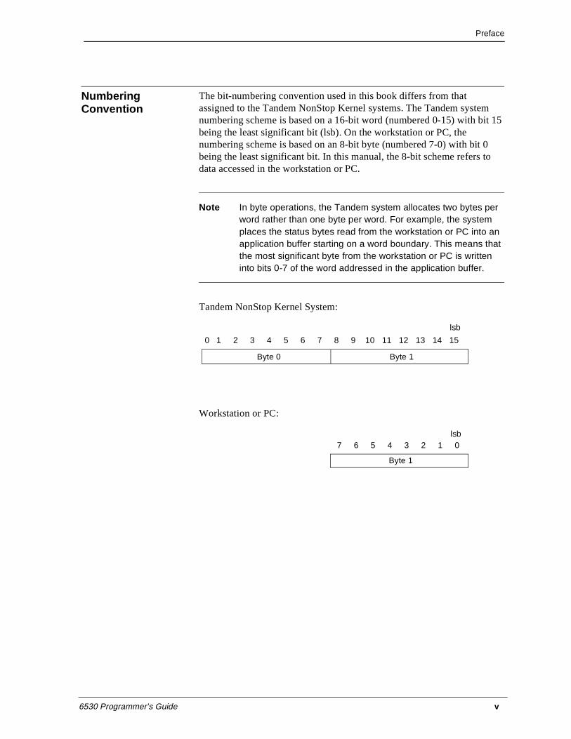
The bit-numbering convention used in this book differs from that assigned to the Tandem NonStop Kernel systems. The Tandem system numbering scheme is based on a 16-bit word (numbered 0-15) with bit 15 being the least significant bit (lsb). On the workstation or PC, the numbering scheme is based on an 8-bit byte (numbered 7-0) with bit 0 being the least significant bit. In this manual, the 8-bit scheme refers to data accessed in the workstation or PC.
Note In byte operations, the Tandem system allocates two bytes per word rather than one byte per word. For example, the system places the status bytes read from the workstation or PC into an application buffer starting on a word boundary. This means that the most significant byte from the workstation or PC is written into bits 0-7 of the word addressed in the application buffer.
Tandem NonStop Kernel System:
Workstation or PC:
0 1 2 3 4 5 6 7 8 9 10 11 12 13 14 15
Byte 0 Byte 1
lsb
7 6 5 4 3 2 1 0
Byte 1
lsb

Preface
vi 6530 Programmer’s Guide
6530 Programmer’s Guide vii
Table of Contents
1 Overview
6530 Features .....................................................................................................1-1
Screen Format ...........................................................................................1-1
Message/Status Line .................................................................................1-2
Error Line .................................................................................................1-2
Modes of Operation ..................................................................................1-3
Conversational mode ......................................................................1-3
Block mode .....................................................................................1-4
6530 Display Memory Organization ........................................................1-5
Conversational Mode Memory Organization .................................1-5
Block Mode Memory Organization ................................................1-5
Video Attributes .......................................................................................1-7
Data Attributes ..........................................................................................1-7
Character Codes ........................................................................................1-8
Escape Sequences .....................................................................................1-9
Keyboard Operation ...............................................................................1-10
Configuration Parameters .......................................................................1-10
Device Control ........................................................................................1-11
Host Communications ............................................................................1-11
6530 Initialization Sequences .................................................................1-12
Terminal Reset .................................................................................................1-14
Soft Reset ................................................................................................1-14
Program Reset ........................................................................................1-14
System Reset ..........................................................................................1-15
Application Programming Interface .................................................................1-15
Table of Contents
viii 6530 Programmer’s Guide
Configuration Parameters ................................................................................ 1-16
Aux1 device name .................................................................................. 1-16
Aux2 device name .................................................................................. 1-16
baud rate ................................................................................................. 1-17
bell column ............................................................................................. 1-17
bell volume ............................................................................................. 1-17
character set ............................................................................................ 1-17
character size .......................................................................................... 1-17
compression enhance ............................................................................. 1-18
cursor type .............................................................................................. 1-18
device name ............................................................................................ 1-18
duplex ..................................................................................................... 1-18
EM3270 support ..................................................................................... 1-18
host name ............................................................................................... 1-18
keyboard ................................................................................................. 1-19
language ................................................................................................. 1-20
local transmit column ............................................................................. 1-20
normal intensity ...................................................................................... 1-20
packet blocking ...................................................................................... 1-21
parity ...................................................................................................... 1-21
PFKey support ........................................................................................ 1-21
Power On mode ...................................................................................... 1-21
print form feed ....................................................................................... 1-21
print line terminator ............................................................................... 1-22
resource name ........................................................................................ 1-22
Return function key ................................................................................ 1-22
RTM support .......................................................................................... 1-22
save configuration .................................................................................. 1-22
screen format .......................................................................................... 1-22
screen saver ............................................................................................ 1-23
session name .......................................................................................... 1-23
SPS ......................................................................................................... 1-23
status line border .................................................................................... 1-23
transmit line ............................................................................................ 1-23
Table of Contents
6530 Programmer’s Guide ix
TS530 screen video attributes .................................................................1-23
TS530 switch refresh rate .......................................................................1-23
window name ..........................................................................................1-24
2 Conversational Mode Operation
Control Codes and Escape Sequences ................................................................2-2
Cursor Location ........................................................................................2-5
Set Cursor Address (DC3) ..............................................................2-6
Set Cursor Address Extended (Esc - D) ..........................................2-6
Read Cursor Address (Esc a) ..........................................................2-6
Cursor Movement .....................................................................................2-7
Cursor Up (Esc A) ..........................................................................2-7
Line Feed (LF) ................................................................................2-8
Cursor Right (Esc C) .......................................................................2-8
Backspace (BS) ...............................................................................2-8
Carriage Return (CR) ......................................................................2-8
Cursor Home (Esc H) .....................................................................2-8
Cursor Home Down (Esc F) ...........................................................2-8
Horizontal Tab (HT) .......................................................................2-8
Tab Settings ..............................................................................................2-9
Set Tab (Esc 1) ................................................................................2-9
Clear Tab (Esc 2) ............................................................................2-9
Clear All Tabs (Esc 3) ....................................................................2-9
Roll/Page Operations ................................................................................2-9
Roll Up (Esc S) ...............................................................................2-9
Roll Down (Esc T) ..........................................................................2-9
Page Up (Esc V) ...........................................................................2-10
Page Down (Esc U) .......................................................................2-10
Display Page (Esc ;) ......................................................................2-10
Clear Display Memory ...........................................................................2-10
Clear Memory to Spaces (Esc I) ...................................................2-10
Erase to End of Memory (Esc J) ...................................................2-10
Erase to End of Line (Esc K) ........................................................2-11
Table of Contents
x 6530 Programmer’s Guide
Video Attributes ..................................................................................... 2-11
Set Video Attributes (Esc 6) ......................................................... 2-14
Set Video Prior Condition Register (Esc 7) ................................. 2-15
Color Video Attributes ........................................................................... 2-15
Color Enhancement Query (Esc ?) ............................................... 2-16
Read 6530 Color Mapping Table (Esc - v) .................................. 2-18
Set/Reset Color Map Table (Esc - q) ........................................... 2-19
Read Color Mapping Table (Esc - v) ........................................... 2-21
Read Color Configuration (Esc - u) ............................................. 2-22
Set Color Configuration (Esc - t) ................................................. 2-23
Configuration Values ............................................................................. 2-24
Read Terminal Configuration (Esc ?) .......................................... 2-30
Set Terminal Configuration (Esc v) ............................................. 2-30
Read I/O Device Configuration (Esc y) ....................................... 2-31
Set I/O Device Configuration (Esc x) .......................................... 2-31
Read String Configuration Parameter (Esc - d) ........................... 2-32
Set String Configuration Parameter (Esc - c) ............................... 2-33
Read VTLAUNCH 6530 Configuration Parameter ( Esc - g ) ...................................................................................... 2-33
RTM Support ......................................................................................... 2-35
RTM Control (Esc - i) .................................................................. 2-36
RTM Data Upload (Esc - j) .......................................................... 2-37
Status Information .................................................................................. 2-38
Read Terminal Status (Esc ^) ....................................................... 2-38
Read Full Revision Level (Esc _) ................................................ 2-39
Get Machine Name (Esc - e) ........................................................ 2-40
Get Current Directory and Redirection Information (Esc - f) ...... 2-40
Device Control ....................................................................................... 2-41
Print Screen (Esc 0) ...................................................................... 2-41
Write to Aux1 or Aux2 Device (Esc - O) ..................................... 2-42
Write to File or Device Name (Esc { ) ......................................... 2-43
Write/Read to File or Device name (Esc } ) ................................ 2-44
Load and Execute an Operating System Program (Esc - V) ........ 2-46
Table of Contents
6530 Programmer’s Guide xi
Report Exec Return Code (Esc - W) .............................................2-47
Disconnect Modem (Esc f) ...........................................................2-48
General Operations .................................................................................2-48
Bell (BEL) .....................................................................................2-48
Delay One Second (Esc @) ..........................................................2-48
Unlock Keyboard (Esc b) .............................................................2-49
Lock Keyboard (Esc c) .................................................................2-49
Simulate Function Key (Esc d) .....................................................2-49
Write to Message Field (Esc o) .....................................................2-49
Reinitialize (Esc q) ........................................................................2-50
Define Enter Key Function (Esc u) ...............................................2-50
Terminate Remote 6530 Operation (Esc - z) ................................2-50
Execute Self Test (Esc z) ..............................................................2-51
Shift Out to G1 Character Set (S0) ...............................................2-51
Shift In to G0 Character Set (S1) ..................................................2-51
Function Keys ...................................................................................................2-51
Keyboard Operations ........................................................................................2-53
3 Block Mode Operation
Fields and Field Attributes (Protect Submode) ..................................................3-1
Modified Data Tags ..................................................................................3-3
Data Types ................................................................................................3-4
Auto-Tab Disable ............................................................................3-5
Upshift ............................................................................................3-6
Alternate Input Device ....................................................................3-6
Control Codes and Escape Sequences ......................................................3-6
Page Operations ......................................................................................3-11
Display Page (Esc ;) ......................................................................3-11
Select Page (Esc :) ........................................................................3-12
Set Max Page Number (Esc p) ......................................................3-12
Cursor and Buffer Addressing ................................................................3-13
Set Cursor Address (DC3) ............................................................3-14
Set Cursor Address Extended (Esc - D) ........................................3-14
Read Cursor Address (Esc a) ........................................................3-15
Table of Contents
xii 6530 Programmer’s Guide
Set Buffer Address (DC1) ............................................................ 3-15
Set Buffer Address Extended (Esc - C) ........................................ 3-16
Cursor Movement .................................................................................. 3-16
Cursor Up (Esc A) ........................................................................ 3-17
Line Feed (LF) ............................................................................. 3-17
Cursor Right (Esc C) .................................................................... 3-17
Backspace (BS) ............................................................................ 3-18
Carriage Return (CR) ................................................................... 3-18
Cursor Home (Esc H) ................................................................... 3-18
Cursor Home Down (Esc F) ......................................................... 3-18
Horizontal Tab (HT) ..................................................................... 3-18
Back Tab (Esc i) ........................................................................... 3-19
Tab Settings ............................................................................................ 3-19
Set Tab (Esc 1) ............................................................................. 3-19
Clear Tab (Esc 2) .......................................................................... 3-19
Clear All Tabs (Esc 3) .................................................................. 3-19
Video Attributes ..................................................................................... 3-20
Set Video Attributes (Esc 6) ......................................................... 3-23
Set Video Prior Condition Register (Esc 7) ................................. 3-24
Color Video Attributes ........................................................................... 3-24
Color Enhancement Query (Esc ?) ............................................... 3-25
Read 6530 Color Mapping Table (Esc - v) .................................. 3-27
Set/Reset Color Map Table (Esc - q) ........................................... 3-28
Read Color Mapping Table (Esc - v) ........................................... 3-30
Read Color Configuration (Esc - u) ............................................. 3-31
Set Color Configuration (Esc - t) ................................................. 3-32
Set 6530 Color Mapping (Esc - x) ............................................... 3-32
Start Enhanced Color Field (Esc ’) .............................................. 3-33
Read Screen With All Attributes (Esc Q) .................................... 3-34
Protect Submode .................................................................................... 3-35
Enter Protect Submode (Esc W) ................................................... 3-35
Exit Protect Submode (Esc X) ..................................................... 3-36
Start Field (GS) ............................................................................ 3-37
Start Field Extended (Esc [ ) ........................................................ 3-38
Table of Contents
6530 Programmer’s Guide xiii
Reset Modified Data Tags (Esc >) ................................................3-38
Define Data Type Table (Esc r) ....................................................3-39
Define Data Type Table Extended (Esc-r) ...................................3-40
Set 40-character line width (Esc 8) ...............................................3-40
Set 80-character line width (Esc 9) ...............................................3-40
Set 40-character screen width (Esc t) ...........................................3-40
EM3270 Submode ..................................................................................3-41
Read Page ...............................................................................................3-41
Read Whole Page / Buffer (Esc <) ...............................................3-44
Read with Address (Esc =) ...........................................................3-45
Read with Address Extended (Esc - J) ..........................................3-46
Read with Address All (Esc ]) ......................................................3-46
Read with Address All Extended (Esc - K) ..................................3-47
Clear Display Memory ...........................................................................3-48
Clear Memory to Spaces (Esc I) ...................................................3-48
Clear Memory to Spaces Extended (Esc - I) .................................3-49
Erase to End of Page (Esc J) .........................................................3-49
Erase to End of Line/Field (Esc K) ...............................................3-49
Editing ....................................................................................................3-50
Insert Line (Esc L) ........................................................................3-50
Delete Line (Esc M) ......................................................................3-50
Insert Character (Esc O) ...............................................................3-51
Delete Character (Esc P) ...............................................................3-51
Configuration Values ..............................................................................3-51
Read Terminal Configuration (Esc ?) ...........................................3-57
Read Field-Selectable Color Configuration ..................................3-59
Set Terminal Configuration (Esc v) ..............................................3-59
Read I/0 Device Configuration (Esc y) .........................................3-60
Set I/0 Device Configuration (Esc x) ............................................3-60
Read String Configuration Parameter (Esc - d) ............................3-61
Set String Configuration Parameter (Esc - c) ...............................3-62
Read VTLAUNCH 6530 Configuration Parameter ( Esc - g ) .....3-63
Table of Contents
xiv 6530 Programmer’s Guide
RTM Support ......................................................................................... 3-64
RTM Control (Esc - i) .................................................................. 3-65
RTM Data Upload (Esc - j) .......................................................... 3-66
PFKey Support ....................................................................................... 3-67
EM3270 Support .................................................................................... 3-67
Set EM3270 Mode (Esc - m) ........................................................ 3-67
Read All Locations (Esc - n) ........................................................ 3-70
Read Keyboard Latch (Esc - o) .................................................... 3-71
Outbound Compression .......................................................................... 3-72
Start Limited Data Compression (DC4) ....................................... 3-72
Start Extended Data Compression (DC2) .................................... 3-73
Status Information .................................................................................. 3-74
Read Terminal Status (Esc ^) ....................................................... 3-74
Read Full Revision Level (Esc _) ................................................ 3-75
Get Machine Name (Esc - e) ........................................................ 3-76
Get Current Directory and Redirection Information (Esc - f) ...... 3-76
Device Control ....................................................................................... 3-77
Print Page (Esc 0) ......................................................................... 3-77
Write to Auxl or Aux2 Device (Esc - 0) ...................................... 3-78
Write to File or Device Name (Esc { ) ......................................... 3-79
Write/Read to File or Device Name (Esc } ) ................................ 3-80
Load and Execute an Operating System Program (Esc - V) ........ 3-82
Report Exec Return Code (Esc - W) ............................................ 3-83
Disconnect Modem (Esc f) ........................................................... 3-84
General Operations ................................................................................ 3-84
Bell (BEL) .................................................................................... 3-84
Define Field Attribute (FS) .......................................................... 3-84
Define/Update Variable Table (Esc - s) ....................................... 3-89
Delay One Second (Esc @) .......................................................... 3-90
Disable Local Line Editing (Esc N) ............................................. 3-91
Unlock Keyboard (Esc b) ............................................................. 3-91
Lock Keyboard (Esc c) ................................................................. 3-91
Simulate Function Key (Esc d) .................................................... 3-91
Write to Message Field (Esc o) .................................................... 3-92
Table of Contents
6530 Programmer’s Guide xv
Reinitialize (Esc q) ........................................................................3-92
Terminate Remote 6530 Operation (Esc - z) ................................3-92
Execute Self Test (Esc z) ..............................................................3-93
Shift Out to G1 Character Set (S0) ...............................................3-93
Shift In to G0 Character Set (S1) ..................................................3-93
Function Keys ...................................................................................................3-93
Keyboard Operations ........................................................................................3-96
4 Tandem NonStop Kernel Application Interface
File System Procedure Calls ...............................................................................4-3
Programming Example .......................................................................................4-5
A ASCII Character Set
B International Characters
C Control Codes and Escape Sequences
D Data Type Table
Index

Table of Contents
xvi 6530 Programmer’s Guide
6530 Programmer’s Guide 1-1
1Overview
This chapter briefly describes the features of the 6530. This chapter also provides descriptions of 6530 configuration parameters.
6530 Features The 6530 provides the following features to enhance terminal operation in online transaction processing environments:
n A 25 row by 80 column screen format, with a message/status and error line separate from the display of other screen data.
n Two major operating modes: conversational and block.
n Display memory for storage of displayable (graphics) data entered from the keyboard or received from the host.
n Video and data attributes for specifying how characters are displayed on the screen and what type of characters can be entered from the keyboard.
n Support for both 7-bit and 8-bit character codes, including the standard ASCII character set and international character sets.
n 6530-compatible keyboard operation, including local editing capabilities, function keys to invoke application-specific functions, and several levels of reset from the keyboard.
n Configuration parameters for selecting options and setting up host communications.
Screen Format The 6530 screen format consists of 25 rows by 80 columns. The cursor type, which is selected by a configuration parameter, can appear as either a blinking underscore or blinking reverse video block.
The first 24 rows of the screen display the characters written into display memory. The bottom (25th) row is reserved and alternately displays two types of lines: a message/status line and an error line. Both lines are stored in an area of memory separate from the rest of the screen display.
Overview
1-2 6530 Programmer’s Guide
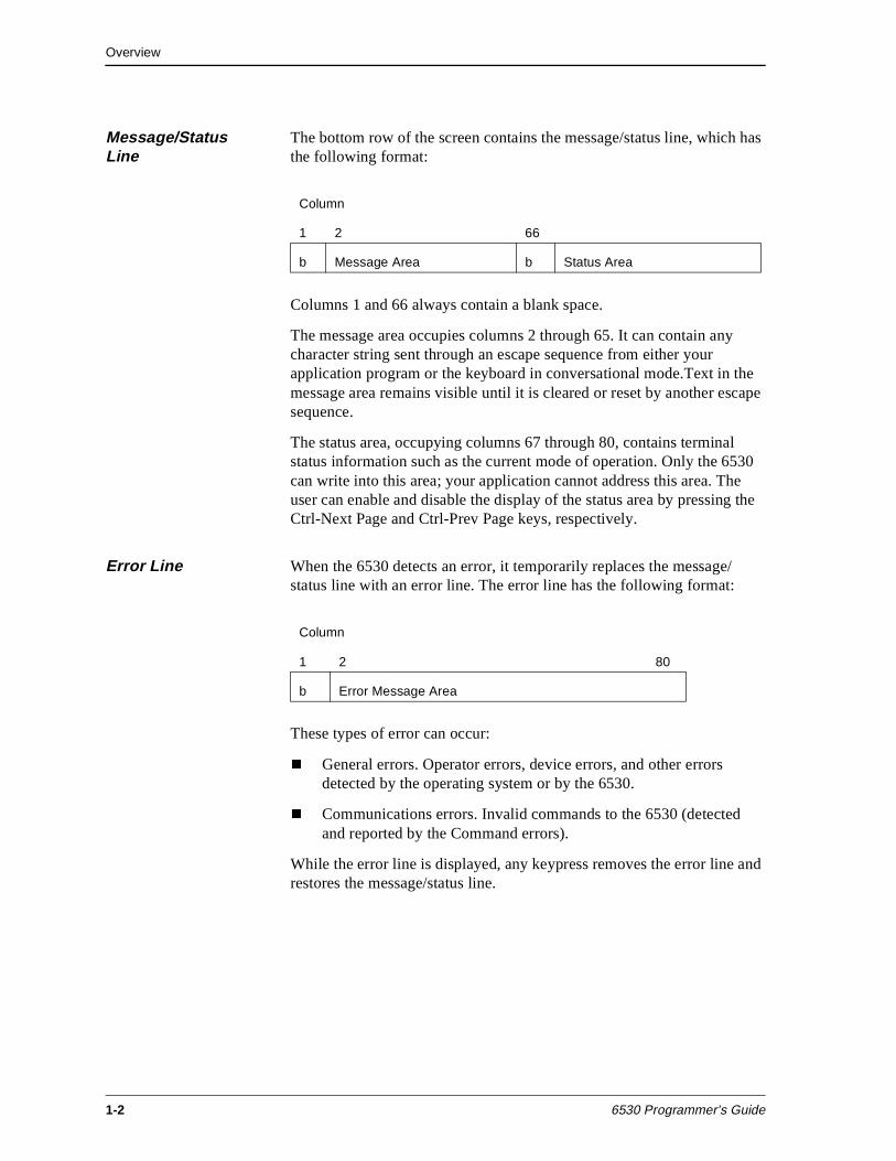
Message/Status Line
The bottom row of the screen contains the message/status line, which has the following format:
Columns 1 and 66 always contain a blank space.
The message area occupies columns 2 through 65. It can contain any character string sent through an escape sequence from either your application program or the keyboard in conversational mode.Text in the message area remains visible until it is cleared or reset by another escape sequence.
The status area, occupying columns 67 through 80, contains terminal status information such as the current mode of operation. Only the 6530 can write into this area; your application cannot address this area. The user can enable and disable the display of the status area by pressing the Ctrl-Next Page and Ctrl-Prev Page keys, respectively.
Error Line When the 6530 detects an error, it temporarily replaces the message/status line with an error line. The error line has the following format:
These types of error can occur:
n General errors. Operator errors, device errors, and other errors detected by the operating system or by the 6530.
n Communications errors. Invalid commands to the 6530 (detected and reported by the Command errors).
While the error line is displayed, any keypress removes the error line and restores the message/status line.
Column
1 2 66
b Message Area b Status Area
Column
1 2 80
b Error Message Area
Overview
6530 Programmer’s Guide 1-3
Modes of Operation The 6530 can operate in one of two major modes:
n Conversational
n Block
The mode selected determines how data is transmitted to the host, as well as how certain control codes, escape sequences, and keyboard operations function. You can select the mode best suited for your particular application. You can also switch modes at different points in your application.
Conversational mode
Conversational mode is useful for applications that need to interact with the 6530 on a line-by-line basis, such as the host Tandem Advanced Command Language (TACL). In this mode, the 6530 transmits data to the host character by character as it is typed on the keyboard. The transfer is terminated when the host receives a line termination character, such as a carriage return (CR) character.
Half duplex
When the communications line is configured for half duplex, the 6530 processes characters entered from the keyboard as it transmits them to the host. The 6530 interprets these characters as graphics (displayable) characters or as control characters. Graphics characters are stored in display memory and appear on the screen. Control characters are not displayed or stored locally; instead, they cause the 6530 to perform various functions. Characters received from the host are also interpreted as graphics or control characters and are handled in the same way.
Full duplex
When the communications line is configured for full duplex, the 6530 only processes characters received from the host. Characters entered from the keyboard are transmitted to the host, but they are not processed by the 6530 until they are echoed back by the host. Characters received from the host are interpreted and processed in the same manner as in half duplex.
Chapter 2 describes the details of conversational mode operation.
Block mode
Block mode allows the application program to control the format of data on the screen. In addition, the 6530 can perform more local processing functions, such as editing tasks, and thus reduce host application processing requirements.
Overview
1-4 6530 Programmer’s Guide
In block mode, the 6530 displays characters typed on the keyboard and stores them in display memory. The 6530 does not transmit any data until the host application issues a read request. Thus, a user can enter multiple lines of data or even a complete screen between transfers to the host. The 6530 transmits data as a block. A block can be a full screen or page of data. Each block begins with a start of text (STX) or start of header (SOH) character and is terminated by an end of text (ETX) and longitudinal redundancy check (LRC) character.
Block mode has two submodes:
n Nonprotect (default). The user can position the cursor anywhere on the screen and enter any type of data.
n Protect. Your application program can divide the screen into fields with assigned video and data attributes.
Chapter 3 describes the details of block mode operation.
Overview
6530 Programmer’s Guide 1-5
6530 Display Memory Organization
A portion of the 6530 memory is reserved for storing data that can be shown on the screen. This includes displayable (graphics) characters entered from the keyboard or received from the host.
Note The message/status and error lines are handled separately.
Enough memory is allocated to fill the screen several times over. Using various cursor or display control keys, the user can select which portion of memory actually appears on the screen. How 6530 display memory is organized and accessed depends on the mode of operation selected.
Conversational Mode Memory Organization
Display memory in conversational mode is organized as one continuous area, similar to a roll of paper. Only 24 contiguous lines of display memory can appear on the screen at one time.
The user or your application can move the cursor around and roll display memory up or down on the screen. Information rolled off the top or bottom of the screen continues to be stored in display memory until all the available display memory lines are used. At this point, an attempt to move the cursor past the last line of memory causes a scroll operation to occur. The scroll operation deletes the first line of display memory, moves all remaining memory lines up one line, and inserts a new blank line at the bottom of display memory
Chapter 2 provides more details about display memory and cursor control in conversational mode.
Block Mode Memory Organization
Display memory in block mode is divided into logical pages, each consisting of 24 lines. The maximum number of pages that can be allocated depends on the number of fields defined when protect submode is used.
Only one page can be displayed at a time, and the screen display cannot cross page boundaries, so rolling operations are disabled. Your application program controls which page is displayed. Typically, the user requests a new page to be displayed through one of the function keys.
Overview
1-6 6530 Programmer’s Guide
Character input from the keyboard occurs at the cursor location on the currently displayed page. Each page has its own cursor, and the cursor for a particular page can be moved without affecting the cursors on other pages. The cursor location is addressed by row and column positions relative to the page. The default cursor address is the home location (row 1, column 1).
When a new page is displayed, the cursor moves to the cursor location stored for that page. This location may be the same as when the page was last displayed, a new location set by your application, or the default home position.
The user can only modify data at the currently displayed page and only at the current cursor location. Your application program, however, can select any page for I/O. For example, while the user is displaying and modifying data on page 1, your application program can read and write to page 3. However, no I/O can be performed across page boundaries. A new page must be selected before its contents are accessible.
Your application program uses buffer addresses for writing data to the currently selected page. Buffer addresses are also row and column positions within the page. The current buffer address is independent of the cursor address for that page and may be the same or different on each page. All explicit cursor movement operations initiated by your program reference the cursor position on the selected page.
Display memory is organized in the same manner for both protect and nonprotect submodes. Protect submode adds the additional functionality of fields. Your application can define any contiguous subset of character positions on a page as a field. Each field can then be assigned its own video and data attributes.
The cursor cannot be positioned into a protected field, either from the keyboard or from your application. An attempt to place the cursor in a protected field results in the cursor moving to the first position of the next unprotected field. Because your application uses buffer addressing for I/O, it can write into any position on the page.
Overview
6530 Programmer’s Guide 1-7
Video Attributes Video attributes can be used in any of the operating modes. They specify how characters appear on the screen. The video attributes available with the 6530 are:
n Blinking or nonblinking
n Normal or alternate intensity
n Normal or reverse video
n Normal or underscored
n Normal or invisible (not displayed)
Some restrictions for attribute combinations exist. Monochrome monitors are unable to display reverse video and underscored characters simultaneously, because display of the reverse video attribute masks the appearance of the underscore attribute. If the workstation or PC is equipped with EGA, CGA, or VGA, video attributes can be mapped that allow display of color. See subsequent chapters for details on color mapping in each operating mode.
Data Attributes Data attributes are available only in the protect submode of block mode. They provide various forms of control over data entered by the user. In addition to video attributes, a field can be assigned combinations of the following data attributes:
n Protect - Controls write-accessibility. Only your application program can write into a protected field.
n Data Type - Identifies the type of data that can be entered into an unprotected field.
n Auto-Tab Disable - Prevents automatic cursor jump.
n Modified Data Tag (MDT) - Identifies fields for subsequent read operations.
n Upshift - Converts all lowercase letters entered from the keyboard to uppercase before displaying them in the field.
n Alternate Input Device (AID) - Defines a field to accept input from the keyboard only, from an AID only, or from either the keyboard or AID.
Chapter 3 provides more details on the data attributes and how to select them.
Overview
1-8 6530 Programmer’s Guide
Character Codes The 6530 can be configured to transmit either 7-bit or 8-bit character codes, with or without parity. The lower 7 bits are used for the standard ASCII character set, which represents 128 different characters. The eighth bit is used for an upper 128-character set, which is the same as the workstation’s or PC’s standard alternate character set.
Both the 7-bit and 8-bit codes represent two types of characters:
n Control characters
n Graphics (displayable) characters
With the 7-bit ASCII codes, control characters are represented in the range of 00H to 1FH. This is referred to as the C0 set. Graphics characters are represented in the range of 20H to 7FH, referred to as the G0 set.
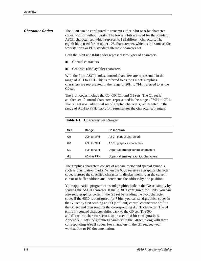
The 8-bit codes include the C0, G0, C1, and G1 sets. The C1 set is another set of control characters, represented in the range of 80H to 9FH. The G1 set is an additional set of graphic characters, represented in the range of A0H to FFH. Table 1-1 summarizes the character set ranges.
The graphics characters consist of alphanumeric and special symbols, such as punctuation marks. When the 6530 receives a graphics character code, it stores the specified character in display memory at the current cursor or buffer address and increments the address by one position.
Your application program can send graphics code in the G0 set simply by sending the ASCII character. If the 6530 is configured for 8 bits, you can also send graphics codes in the G1 set by sending the 8-bit character code. If the 6530 is configured for 7 bits, you can send graphics codes in the G1 set by first sending an SO (shift out) control character to shift to the G1 set and then sending the corresponding ASCII character. The SI (shift in) control character shifts back to the G0 set. The SO and SI control characters can also be used in 8-bit configurations. Appendix A lists the graphics characters in the G0 set, along with their corresponding ASCII codes. For characters in the G1 set, see your workstation or PC documentation.
Table 1-1. Character Set Ranges
Set Range Description
C0 00H to 1FH ASCII control characters
G0 20H to 7FH ASCII graphics characters
C1 80H to 9FH Upper (alternate) control characters
G1 A0H to FFH Upper (alternate) graphics characters
Overview
6530 Programmer’s Guide 1-9
The control characters specify a set of communications and terminal control functions, such as moving the cursor on the screen. When the 6530 receives a recognized control character, it performs the specified function. Unrecognized control characters are ignored. Control characters are not stored in display memory, and are not shown on the screen.
Your application program can send control characters to the 6530 by sending the code associated with that character. In conversational mode, the user can generate ASCII control characters from the keyboard by pressing the Ctrl key followed by an alphanumeric key or by pressing special keys such as the backspace key.
Escape Sequences Control codes are extended by escape sequences to increase terminal functionality. An escape sequence consists of a string of ASCII characters, starting with the Esc (1BH) control character and followed by one or more graphic characters that comprise the escape code and any additional parameters. When the 6530 receives a recognized escape sequence, it performs the function specified. Unrecognized escape sequences cause the 6530 to issue a command error: the DEL symbol appears at the cursor position.
Your application program can send escape sequences to the 6530 by sending the ASCII code for the Esc character (1BH) followed by the appropriate graphic character(s). In conversational mode, the user can generate escape sequences from the keyboard by pressing the Esc key followed by one or more alphanumeric keys.
Appendix A lists the control characters in the C0 and Cl sets. Not all of these are recognized by the 6530. Appendix C summarizes all the recognized control codes and escape sequences. The control codes and escape sequences available depend on the mode of operation selected. Chapters 2 and 3 describe the codes and sequences available in conversational and block mode.
The 6530 also supports character sets and keyboards for use in countries other than the U.S. The user or your application can set the language to be used with a configuration parameter. The supported languages are:
n ASCII (U.S. English)
n Belgian
n Cyrillic
n Danish
n English (UK)
n French (AZERTY and QUERTY)
n German
Overview
1-10 6530 Programmer’s Guide
n Italian (supported in 8-bit versions only)
n Norwegian
n Portuguese
n Spanish
n Swedish/Finnish
n Swiss-French
n Swiss-German
When a particular language is selected, certain ASCII characters in the graphic range are replaced by characters used in that country. These are listed in Appendix B.
Keyboard Operation When a PC or workstation is running PC6530, these keys perform 6530 functions:
n Alphanumeric keys generate displayable (graphic) characters.
n Cursor/display control keys move the cursor on the screen and roll display memory (conversational mode).
n Function keys transmit messages to the host to invoke application-defined functions.
n Special-purpose keys perform a variety of terminal functions, such as printing the contents of the screen.
The keyboard operations available depend on the mode of operation selected. The type of workstation or PC keyboard layout can be selected by a configuration parameter. Chapters 2 and 3 describe the codes and sequences available for configuration in conversational and block modes.
Configuration Parameters
Configuration parameters allow users to select 6530 options, such as cursor type, bell column, and screen image intensity. Configuration parameters are also used for communications line settings, such as baud rate and parity. Initially, the 6530 assumes default values for these parameters. The user can change these values by specifying new settings in a 6530 initialization file.
For more information about the 6530 initialization file or about the 6530 configuration utility, refer to the user’s guide for the terminal or terminal emulator.
Your application program can use escape sequences to read the configuration parameters currently selected and reset them, if necessary.
Overview
6530 Programmer’s Guide 1-11
Device Control The 6530 provides access to operating system devices or filenames, such as printers or disk files. Supported features include:
n Screen printing – Allows the user or your application to print the contents of the display screen or the selected page.
n Pass-through printing – Allows your application to print any type of data.
n Write and write/read operations – Allows your application to perform I/O operations on any operating system filename or device.
n Exec function (conversational and block modes only) – Enables your application to start execution of PC operating system programs.
See “Device Control” on page 2-41 and on page 3-77 for specific information regarding your application’s implementation of escape sequences for 6530 device control functions in conversational and block modes.
Host Communications
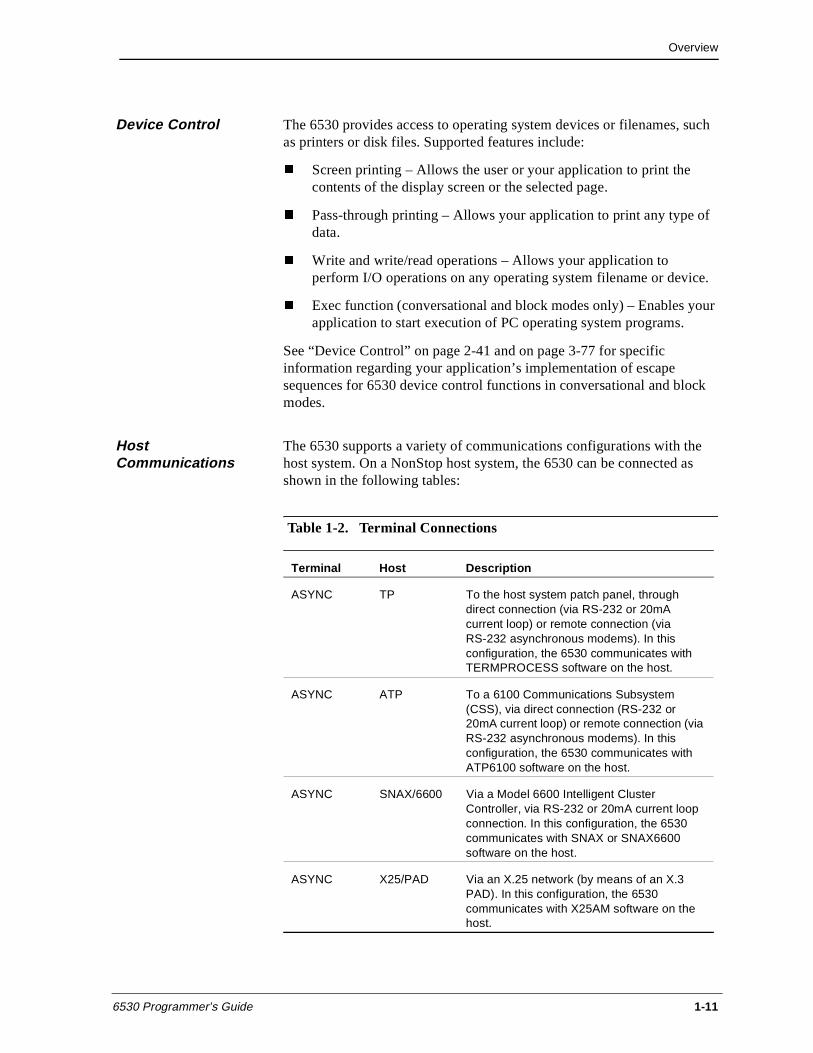
The 6530 supports a variety of communications configurations with the host system. On a NonStop host system, the 6530 can be connected as shown in the following tables:
Table 1-2. Terminal Connections
Terminal Host Description
ASYNC TP To the host system patch panel, through direct connection (via RS-232 or 20mA current loop) or remote connection (via RS-232 asynchronous modems). In this configuration, the 6530 communicates with TERMPROCESS software on the host.
ASYNC ATP To a 6100 Communications Subsystem (CSS), via direct connection (RS-232 or 20mA current loop) or remote connection (via RS-232 asynchronous modems). In this configuration, the 6530 communicates with ATP6100 software on the host.
ASYNC SNAX/6600 Via a Model 6600 Intelligent Cluster Controller, via RS-232 or 20mA current loop connection. In this configuration, the 6530 communicates with SNAX or SNAX6600 software on the host.
ASYNC X25/PAD Via an X.25 network (by means of an X.3 PAD). In this configuration, the 6530 communicates with X25AM software on the host.
Overview
1-12 6530 Programmer’s Guide
TERMPROCESS, ATP6100, SNAX, SNAX6600, X25AM, and WS6530 are I/O processes or access methods that manage and control the communications link. The I/O processes handle data blocking and establish the communications protocols required. For the most part, the communications interface is transparent to your application.
1. The 6530 responds with either an ACK or NAK control character depending on whether the LRC is good or bad. If the request is to enter the same mode that the terminal is already in, the ACK or NAK is still sent, but no other action occurs.
2. On a NAK, the host retransmits the mode-switch message.
3. On an ACK, the mode switch completes with the 6530 ready to receive data from the host.
6530 Initialization Sequences
The 6530 starts operation in the mode selected by the mode configuration parameter. Usually, this should be set to conversational mode when the workstation or PC is connected to a NonStop host.
When the mode configuration parameter is set to conversational mode, the 6530 transmits two control characters, ENQ (05H) and CR (0DH), to the host to indicate that the 6530 has been started. The user can then log on to the host and access application programs.
On a NonStop host system, your application program can switch modes by issuing a SETMODE 8 file system procedure call. The I/O process handles the protocol required to ensure a smooth transition between modes. The mode-switching protocol is as follows:
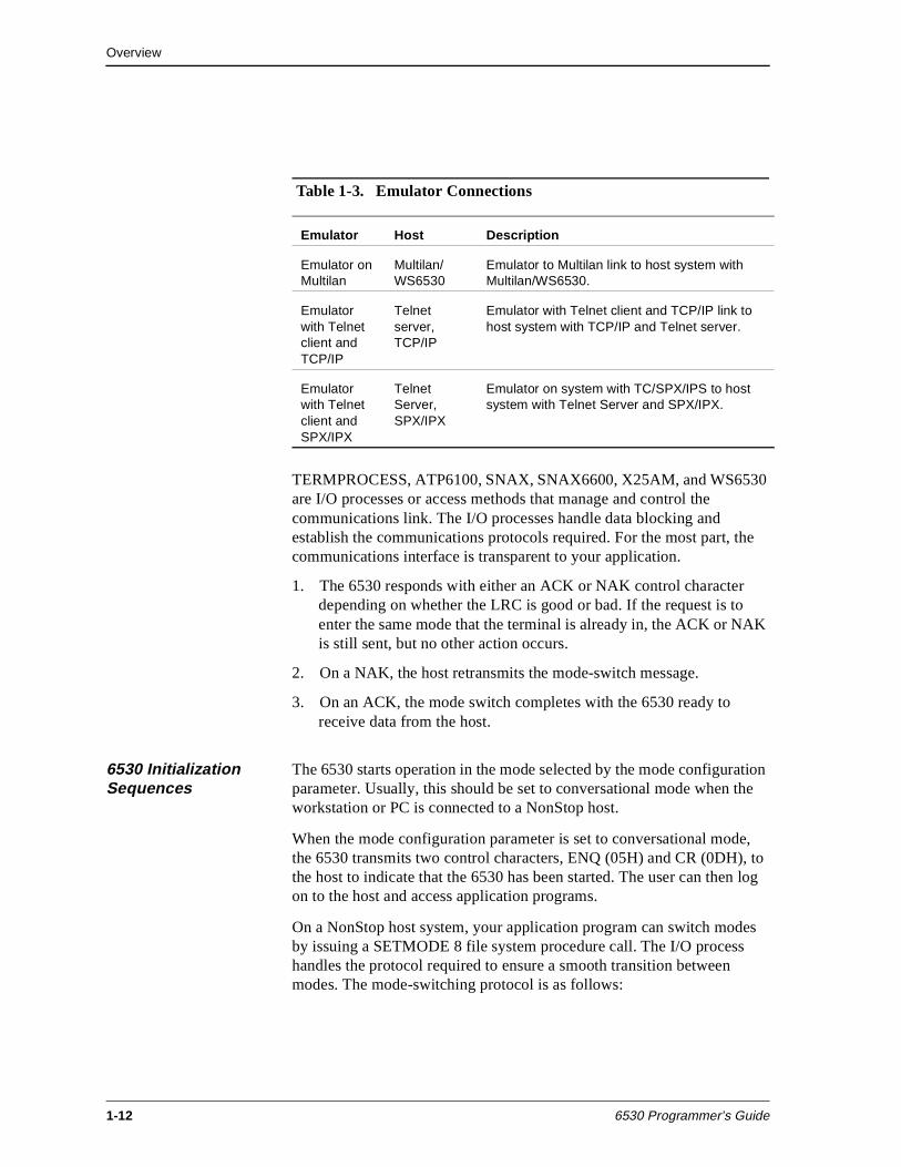
Table 1-3. Emulator Connections
Emulator Host Description
Emulator on Multilan
Multilan/WS6530
Emulator to Multilan link to host system with Multilan/WS6530.
Emulator with Telnet client and TCP/IP
Telnet server, TCP/IP
Emulator with Telnet client and TCP/IP link to host system with TCP/IP and Telnet server.
Emulator with Telnet client and SPX/IPX
Telnet Server, SPX/IPX
Emulator on system with TC/SPX/IPS to host system with Telnet Server and SPX/IPX.
Overview
6530 Programmer’s Guide 1-13
The host sends the terminal a mode switch message of the form:
SOH mode ETX LRC
where:
SOH, ETX, and LRC are communications control characters. SOH acts as a start of header for the message. ETX indicates the end of text for the message. LRC is a longitudinal redundancy check character used to detect errors in the transmission.
mode is either C for conversational or B for block, to specify the new mode of operation.
When the 6530 changes modes, it performs one of the following initialization sequences:
Switch from conversational to block mode
n Locks the keyboard.
n Sets the submode to nonprotect.
n Sets the maximum number of pages to the default or the last setting of the set max page number (Esc p) escape sequence. See “Set Max Page Number (Esc p)” on page 3-12.
n Clears all pages to spaces except page 1, which retains the text that was displayed on the screen in conversational mode.
n Sets the display page and the select page to page 1.
n Sets the cursor address and buffer address for all pages to row 1, column 1 (home position).
n Clears all horizontal tab stops.
n Enables local line editing.
n Sets insert mode to off.
n Sets the video prior condition register to normal video.
n Sets the data type table to its default values. (See Appendix D.)
n Clears the message area in the message/status line and displays BLOCK in the status area.
Overview
1-14 6530 Programmer’s Guide
Switch from block to conversational mode
n Blank fills all lines in display memory.
n Sets the cursor address to row1, column 1, and displays the first 24 lines of memory on the screen.
n Clears all horizontal tab stops.
n Sets the video prior condition register to normal video.
n Clears the message area in the message/status line and displays CONV in the status area.
n Unlocks the keyboard.
Terminal Reset A PC6530 user can perform a reset from the keyboard. The 6530 supports three types of reset, allowing different levels of recovery from errors.
Soft Reset A soft reset is typically used to unlock the keyboard when it becomes accidentally locked by the application. The soft reset function performs the following functions:
n Sounds the bell.
n Unlocks the keyboard (unless page 0 is displayed).
n Terminates any escape sequence in progress.
n Flushes the Aux1 print buffer.
n Resets the SI/SO state (that is shifts into the G0 character set).
n Erases any error message in the error line and restores the message/status line.
n Turns off character insert mode.
n The soft reset function restarts the 6530 from its current state and does not alter or erase any part of display memory. The user can invoke a soft reset with the Ctrl-Backspace keys.
Program Reset A program reset can be used to abort a host application program. The program reset clears display memory and restarts the 6530. The user can invoke a program reset with the Alt-Backspace keys.
Overview
6530 Programmer’s Guide 1-15
System Reset A system reset clears all workstation or PC memory and reloads the operating system. It is equivalent to cycling power off and on, except that the power-on self test is not performed. After a system reset, the user must restart the 6530. The user can invoke a system reset with the Ctrl-Alt-Del keys.
Application Programming Interface
The way in which your application program interacts with the 6530 depends on the host operating system.
On a NonStop host, your application program interacts with the 6530 through procedure calls to the Tandem NonStop Kernel file system. These procedure calls request various I/O operations, such as:
n CONTROL – Executes device-dependent operations on an open device. Used for forms control and modem connect/disconnect.
n SETMODE – Sets or clears device-dependent functions for the workstation or PC, such as switching to block or conversational mode.
n WRITE – Sends data to the 6530 (displayable data, control codes, and escape sequences).
n READ – Gets data from the 6530.
n WRITEREAD – Sends data to the 6530 and waits for a response. Useful for prompting the user for information in conversational mode and for sending control codes and escape sequences that initiate reads from the 6530, such as read cursor address.
These are generic procedure calls that can be used regardless of the actual communications configuration. The file system accesses the appropriate I/O process to handle the transfer of data over the communications line. Chapter 4 provides more information on the Tandem NonStop Kernel programming interface and gives an example application.
Overview
1-16 6530 Programmer’s Guide
Configuration Parameters
This section provides descriptions of 6530 configuration parameters that can be programmed by the host.
The 6530 has a number of configuration parameters, which select options and set up the line for communications with the host system. The user can set the 6530 parameters on the MS-DOS command line or by using the 6530 initialization file.
Through escape sequences, your application can read current configuration parameters. If necessary, your application can change many of these parameters to ensure proper operation. The following paragraphs describe the parameters that can be set from your application. Chapters 2 and 3 describe the escape sequences used to read and set configuration parameters in each of the operating modes. The description of escape sequences includes tables that list values allowed for each parameter.
With PC6530, some parameters can only be set at the workstation or PC (such as the exec function and the command error response). Your application cannot reset the values for these parameters, and no values are returned for them on a read operation. These parameters are explained in the PC6530 user’s guide. A few other parameters are maintained for compatibility with the 6530 (such as key click volume). The 6530 returns values for them to your application on read operations, but they have no meaning for the workstation or PC.
Aux1 device name Specifies an operating system device or file name to which screen data or data generated by your application can be directed. Set with the Esc x T sequence. For conversational mode, see “Set I/O Device Configuration (Esc x)” on page 2-31. For block mode, see “Set I/0 Device Configuration (Esc x)” on page 3-60.
Aux2 device name Specifies an operating system device or file name to which data generated by your application can be directed. Set with the Esc x T sequence. For conversational mode, see “Set I/O Device Configuration (Esc x)” on page 2-31. For block mode, see “Set I/0 Device Configuration (Esc x)” on page 3-60.
Overview
6530 Programmer’s Guide 1-17
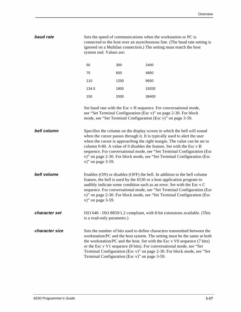
baud rate Sets the speed of communications when the workstation or PC is connected to the host over an asynchronous line. (The baud rate setting is ignored on a Multilan connection.) The setting must match the host system end. Values are:
Set baud rate with the Esc v H sequence. For conversational mode,see “Set Terminal Configuration (Esc v)” on page 2-30. For block mode, see “Set Terminal Configuration (Esc v)” on page 3-59.
bell column Specifies the column on the display screen in which the bell will sound when the cursor passes through it. It is typically used to alert the user when the cursor is approaching the right margin. The value can be set to column 0-80. A value of 0 disables the feature. Set with the Esc v B sequence. For conversational mode, see “Set Terminal Configuration (Esc v)” on page 2-30. For block mode, see “Set Terminal Configuration (Esc v)” on page 3-59.
bell volume Enables (ON) or disables (OFF) the bell. In addition to the bell column feature, the bell is used by the 6530 or a host application program to audibly indicate some condition such as an error. Set with the Esc v C sequence. For conversational mode, see “Set Terminal Configuration (Esc v)” on page 2-30. For block mode, see “Set Terminal Configuration (Esc v)” on page 3-59.
character set ISO 646 - ISO 8859/1.2 compliant, with 8-bit extensions available. (This is a read-only parameter.)
character size Sets the number of bits used to define characters transmitted between the workstation/PC and the host system. The setting must be the same at both the workstation/PC and the host. Set with the Esc v V0 sequence (7 bits) or the Esc v V1 sequence (8 bits). For conversational mode, see “Set Terminal Configuration (Esc v)” on page 2-30. For block mode, see “Set Terminal Configuration (Esc v)” on page 3-59.
50 300 2400
75 600 4800
110 1200 9600
134.5 1800 19200
150 2000 38400
Overview
1-18 6530 Programmer’s Guide
compression enhance
Turns outbound data compression on or off (for block mode only). (See “Outbound Compression” on page 3-72.)
cursor type Determines how the cursor appears on the screen: an underscore or a reverse video block. Set with the Esc v A sequence. For conversational mode, see “Set Terminal Configuration (Esc v)” on page 2-30. For block mode, see “Set Terminal Configuration (Esc v)” on page 3-59.
device name Sets the name for the communications driver used. (This value is set by the user. For more information, see the PC6530 or TS530 user’s guide.)
duplex Selects either half or full duplex communications with the host when conversational mode is used. Set with the Esc v J sequence. For conversational mode, see “Set Terminal Configuration (Esc v)” on page 2-30. For block mode, see “Set Terminal Configuration (Esc v)” on page 3-59.
EM3270 support For block mode only, enables/disables support of certain IBM 3270 terminal functions (such as unformatted mode, wraparound fields, handling of null/spaces, and cursor positioning). See “Set EM3270 Mode (Esc - m)” on page 3-67.
host name For Multilan connections, sets the name of the host. (This value is set by the user. For more information, see the PC6530 or TS530 user’s guide.)
Overview
6530 Programmer’s Guide 1-19
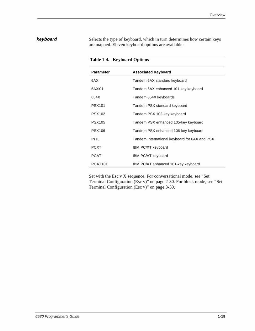
keyboard Selects the type of keyboard, which in turn determines how certain keys are mapped. Eleven keyboard options are available:
Set with the Esc v X sequence. For conversational mode, see “Set Terminal Configuration (Esc v)” on page 2-30. For block mode, see “Set Terminal Configuration (Esc v)” on page 3-59.
Table 1-4. Keyboard Options
Parameter Associated Keyboard
6AX Tandem 6AX standard keyboard
6AXl01 Tandem 6AX enhanced 101-key keyboard
654X Tandem 654X keyboards
PSX101 Tandem PSX standard keyboard
PSX102 Tandem PSX 102-key keyboard
PSX105 Tandem PSX enhanced 105-key keyboard
PSX106 Tandem PSX enhanced 106-key keyboard
INTL Tandem International keyboard for 6AX and PSX
PCXT IBM PC/XT keyboard
PCAT IBM PC/AT keyboard
PCAT101 IBM PC/AT enhanced 101-key keyboard
Overview
1-20 6530 Programmer’s Guide
language Defines which language character set is used for displaying the graphics characters. The supported languages are:
n ASCII (U.S. English)
n Belgian
n Cyrillic
n Danish
n English (UK)
n French (AZERTY and QUERTY)
n German
n Italian (supported in 8-bit versions only)
n Norwegian
n Portuguese
n Spanish
n Swedish/Finnish
n Swiss-French
n Swiss-German
Set with the Esc v F sequence. For conversational mode, see “Set Terminal Configuration (Esc v)” on page 2-30. For block mode, see “Set Terminal Configuration (Esc v)” on page 3-59.
local transmit column
Used for local action (Alt-Enter keys) in conversational mode. It specifies the beginning column for a line that is to be retransmitted to the host. For example, the user can use local action to retransmit a long command string already entered. Only the characters between the column specified by this parameter and the column preceding the current cursor position are transmitted. Set with the Esc v U sequence. For conversational mode, see “Set Terminal Configuration (Esc v)” on page 2-30. For block mode, see “Set Terminal Configuration (Esc v)” on page 3-59.
normal intensity Sets the normal screen intensity for the 6530. It can be set to high or low. Set with the Esc v T sequence. For conversational mode, see “Set Terminal Configuration (Esc v)” on page 2-30. For block mode, see “Set Terminal Configuration (Esc v)” on page 3-59.
Overview
6530 Programmer’s Guide 1-21
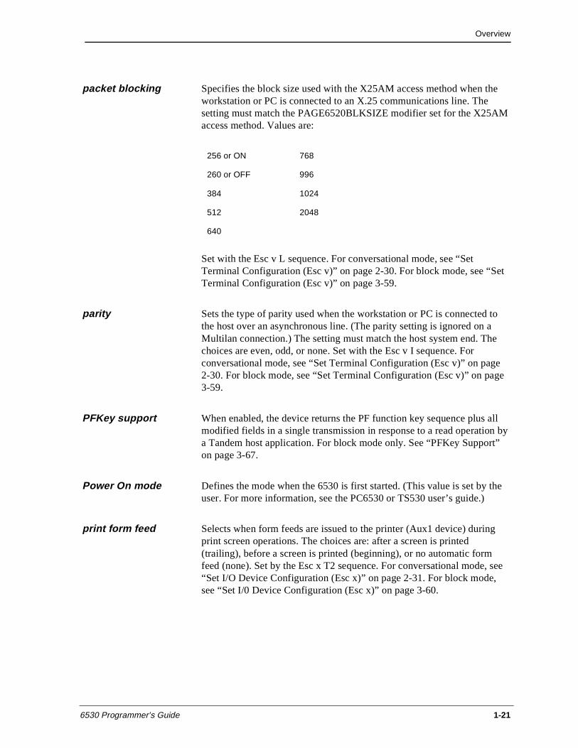
packet blocking Specifies the block size used with the X25AM access method when the workstation or PC is connected to an X.25 communications line. The setting must match the PAGE6520BLKSIZE modifier set for the X25AM access method. Values are:
Set with the Esc v L sequence. For conversational mode, see “Set Terminal Configuration (Esc v)” on page 2-30. For block mode, see “Set Terminal Configuration (Esc v)” on page 3-59.
parity Sets the type of parity used when the workstation or PC is connected to the host over an asynchronous line. (The parity setting is ignored on a Multilan connection.) The setting must match the host system end. The choices are even, odd, or none. Set with the Esc v I sequence. For conversational mode, see “Set Terminal Configuration (Esc v)” on page 2-30. For block mode, see “Set Terminal Configuration (Esc v)” on page 3-59.
PFKey support When enabled, the device returns the PF function key sequence plus all modified fields in a single transmission in response to a read operation by a Tandem host application. For block mode only. See “PFKey Support” on page 3-67.
Power On mode Defines the mode when the 6530 is first started. (This value is set by the user. For more information, see the PC6530 or TS530 user’s guide.)
print form feed Selects when form feeds are issued to the printer (Aux1 device) during print screen operations. The choices are: after a screen is printed (trailing), before a screen is printed (beginning), or no automatic form feed (none). Set by the Esc x T2 sequence. For conversational mode, see “Set I/O Device Configuration (Esc x)” on page 2-31. For block mode, see “Set I/0 Device Configuration (Esc x)” on page 3-60.
256 or ON 768
260 or OFF 996
384 1024
512 2048
640
Overview
1-22 6530 Programmer’s Guide
print line terminator Selects the function that terminates a line on the printer (Auxl device) during print screen operations. The choices are: carriage return (CR), line feed (LF), and carriage return plus line feed (CR_LF). Set by the Esc x T2 sequence. For conversational mode, see “Set I/O Device Configuration (Esc x)” on page 2-31. For block mode, see “Set I/0 Device Configuration (Esc x)” on page 3-60.
resource name On Multilan connections, specifies the name of the host system process to be started when establishing a dynamic link. This parameter is set by the user. For more information, see the PC6530 or TS530 user’s guide, or the Multilan documentation.
Return function key Defines whether the Return key is regarded as an additional function key in block mode. Set by the Esc v M sequence. For conversational mode, see “Set Terminal Configuration (Esc v)” on page 2-30. For block mode, see “Set Terminal Configuration (Esc v)” on page 3-59.
RTM support Allows implementation of Response Time Measurement functions (enabled automatically in block mode) that provide collection of information based on terminal-to-host response times. Configurable as a measurement of the interval of time between the press of an F-key at the terminal and the first character received in response from the host, or between the press of an F-key at the terminal and the receipt of the keyboard unlock command from the host. The 6530 allows configuration of RTM data collection parameters from 0 centiseconds to infinity. RTM support also includes a Definite Response facility based on the measurement of the interval of time between a host request and an expected 6530 response. Set by the Esc v j sequence. For conversational mode, see “Set Terminal Configuration (Esc v)” on page 2-30. For block mode, see “Set Terminal Configuration (Esc v)” on page 3-59.
save configuration Saves configuration parameters and values in non-volatile memory. For the TS530 only.
screen format This read-only parameter indicates whether normal addressing or extending addressing is used. Normal addressing allows access to all positions currently available on the screen (25 lines x 80 columns). Extended addressing capability is provided for access to possible future enhancements in screen formats, such as more rows or columns. For more information, see “Cursor Location” on page 2-5.
Overview
6530 Programmer’s Guide 1-23
screen saver Selects the time interval (in minutes) for the screen saver feature. Set by the Esc v P sequence. For conversational mode, see “Set Terminal Configuration (Esc v)” on page 2-30. For block mode, see “Set Terminal Configuration (Esc v)” on page 3-59.
session name Only used on a Multilan connection when the 6530 is running under MS-DOS. Sets the name for a 6530 session when using a nonswitched access mode. This allows the user to terminate the 6530 without automatically being logged off of the host process. This parameter is set by the user. For more information, see the PC6530 or TS530 user’s guide, or the Multilan documentation.
SPS Only used on a Multilan connection. Sets the startup parameter string (if needed) for a host process when establishing a dynamic link. The host process to be started is specified by the resource name parameter. This parameter is set by the user. For more information, see the PC6530 or TS530 user’s guide, or the Multilan documentation.
status line border Designates whether the status line (the last line on the page) is separated from the rest of the lines by a border. This parameter is supported on read operations only; you cannot change the designation. This parameter is set by the user. For more information, see the PC6530 or TS530 user’s guide.
transmit line Sets a string that is automatically transmitted to the host system when the 6530 is started. For example, this can be used to send a command to the host or transmit modem commands over the communications line. This parameter is set by the user. For more information, see the PC6530 or TS530 user’s guide.
TS530 screen video attributes
Allows TS530 display configuration for: no screen display, reverse video, and reverse video with overscan. This parameter is set by the user. See the TS530 user’s guide for more information.
TS530 switch refresh rate
Allows switching of TS530 display refresh rate between 71 and 82Hz. This parameter is set by the user. See the TS530 user’s guide for more information.
Overview
1-24 6530 Programmer’s Guide
window name Only used on a Multilan connection. Specifies the name of the host window with which the 6530 communicates for a static link. The window must be configured on the host system, and you must include the host system name with the window name. This parameter is set by the user. For more information, see the PC6530 or TS530 user’s guide, or the Multilan documentation.
6530 Programmer’s Guide 2-1
2Conversational Mode Operation
Conversational mode is useful for applications that need to interact with the 6530 on a line-by-line basis. The 6530 transmits data to the host one character at a time as it is typed on the keyboard. The transfer is terminated by a line termination character typically, a CR (0DH).
The 6530 interprets incoming data as either graphic (displayable) characters or control (non-displayable) characters and processes them accordingly. When the 6530 is configured for half-duplex, the 6530 processes characters entered on the keyboard as it transmits them to the host. When the 6530 is configured for full-duplex, the 6530 processes only characters received from the host; characters entered on the keyboard are not processed until they are echoed back by the host.
Display memory in conversational mode is organized as one continuous roll. Only 24 lines can appear on the screen at one time. Character input from either the host or the keyboard takes place at the current cursor location on the screen. After each character input, the cursor advances one position. Control codes, escape sequences, and keyboard operations are available to move the cursor on the screen, to roll display memory, and to perform other terminal operations.
This chapter provides detailed descriptions of control codes and escape sequences, function keys and other keyboard operations available in conversational mode.
Conversational Mode Operation
2-2 6530 Programmer’s Guide
Control Codes and Escape Sequences
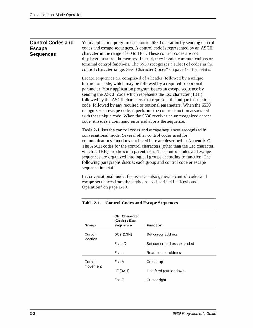
Your application program can control 6530 operation by sending control codes and escape sequences. A control code is represented by an ASCII character in the range of 00 to 1FH. These control codes are not displayed or stored in memory. Instead, they invoke communications or terminal control functions. The 6530 recognizes a subset of codes in the control character range. See “Character Codes” on page 1-8 for details.
Escape sequences are comprised of a header, followed by a unique instruction code, which may be followed by a required or optional parameter. Your application program issues an escape sequence by sending the ASCII code which represents the Esc character (1BH) followed by the ASCII characters that represent the unique instruction code, followed by any required or optional parameters. When the 6530 recognizes an escape code, it performs the control function associated with that unique code. When the 6530 receives an unrecognized escape code, it issues a command error and aborts the sequence.
Table 2-1 lists the control codes and escape sequences recognized in conversational mode. Several other control codes used for communications functions not listed here are described in Appendix C. The ASCII codes for the control characters (other than the Esc character, which is 1BH) are shown in parentheses. The control codes and escape sequences are organized into logical groups according to function. The following paragraphs discuss each group and control code or escape sequence in detail.
In conversational mode, the user can also generate control codes and escape sequences from the keyboard as described in “Keyboard Operation” on page 1-10.
Table 2-1. Control Codes and Escape Sequences
Group
Ctrl Character (Code) / Esc Sequence Function
Cursor location
DC3 (13H) Set cursor address
Esc - D Set cursor address extended
Esc a Read cursor address
Cursor movement
Esc A Cursor up
LF (0AH) Line feed (cursor down)
Esc C Cursor right
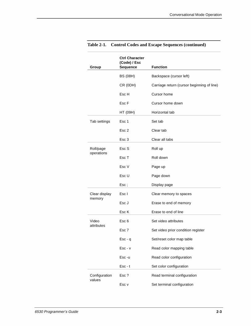
Conversational Mode Operation
6530 Programmer’s Guide 2-3
BS (08H) Backspace (cursor left)
CR (0DH) Carriage return (cursor beginning of line)
Esc H Cursor home
Esc F Cursor home down
HT (09H) Horizontal tab
Tab settings Esc 1 Set tab
Esc 2 Clear tab
Esc 3 Clear all tabs
Roll/page operations
Esc S Roll up
Esc T Roll down
Esc V Page up
Esc U Page down
Esc ; Display page
Clear display memory
Esc I Clear memory to spaces
Esc J Erase to end of memory
Esc K Erase to end of line
Video attributes
Esc 6 Set video attributes
Esc 7 Set video prior condition register
Esc - q Set/reset color map table
Esc - v Read color mapping table
Esc -u Read color configuration
Esc - t Set color configuration
Configuration values
Esc ? Read terminal configuration
Esc v Set terminal configuration
Table 2-1. Control Codes and Escape Sequences (continued)
Group
Ctrl Character (Code) / Esc Sequence Function
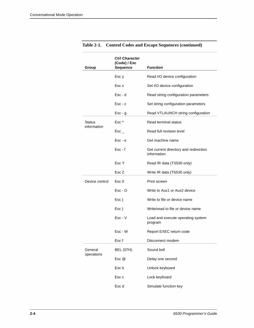
Conversational Mode Operation
2-4 6530 Programmer’s Guide
Esc y Read I/O device configuration
Esc x Set I/O device configuration
Esc - d Read string configuration parameters
Esc - c Set string configuration parameters
Esc - g Read VTLAUNCH string configuration
Status information
Esc ^ Read terminal status
Esc _ Read full revision level
Esc - e Get machine name
Esc - f Get current directory and redirection information
Esc Y Read IR data (TS530 only)
Esc Z Write IR data (TS530 only)
Device control Esc 0 Print screen
Esc - O Write to Aux1 or Aux2 device
Esc { Write to file or device name
Esc } Write/read to file or device name
Esc - V Load and execute operating system program
Esc - W Report EXEC return code
Esc f Disconnect modem
General operations
BEL (07H) Sound bell
Esc @ Delay one second
Esc b Unlock keyboard
Esc c Lock keyboard
Esc d Simulate function key
Table 2-1. Control Codes and Escape Sequences (continued)
Group
Ctrl Character (Code) / Esc Sequence Function
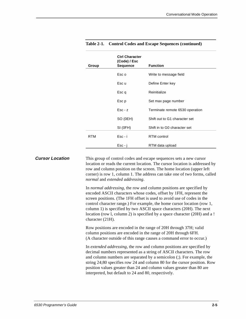
Conversational Mode Operation
6530 Programmer’s Guide 2-5
Cursor Location This group of control codes and escape sequences sets a new cursor location or reads the current location. The cursor location is addressed by row and column position on the screen. The home location (upper left corner) is row 1, column 1. The address can take one of two forms, called normal and extended addressing.
In normal addressing, the row and column positions are specified by encoded ASCII characters whose codes, offset by 1FH, represent the screen positions. (The 1FH offset is used to avoid use of codes in the control character range.) For example, the home cursor location (row 1, column 1) is specified by two ASCII space characters (20H). The next location (row l, column 2) is specified by a space character (20H) and a ! character (21H).
Row positions are encoded in the range of 20H through 37H; valid column positions are encoded in the range of 20H through 6FH. (A character outside of this range causes a command error to occur.)
In extended addressing, the row and column positions are specified by decimal numbers represented as a string of ASCII characters. The row and column numbers are separated by a semicolon (;). For example, the string 24;80 specifies row 24 and column 80 for the cursor position. Row position values greater than 24 and column values greater than 80 are interpreted, but default to 24 and 80, respectively.
Esc o Write to message field
Esc u Define Enter key
Esc q Reinitialize
Esc p Set max page number
Esc - z Terminate remote 6530 operation
SO (0EH) Shift out to G1 character set
SI (0FH) Shift in to G0 character set
RTM Esc - i RTM control
Esc - j RTM data upload
Table 2-1. Control Codes and Escape Sequences (continued)
Group
Ctrl Character (Code) / Esc Sequence Function
Conversational Mode Operation
2-6 6530 Programmer’s Guide
The type of addressing used depends on the control or escape sequence you use. You can choose between the sequence that uses normal addressing and the one that uses extended addressing. Normal addressing allows access to all positions currently available on the screen. The extended addressing sequences also provide access to all current screen positions and, in addition, allow for possible future enhancements in screen formats, such as more rows or columns.
Set Cursor Address (DC3)
The DC3 control character (l3H) sets a new cursor position on the screen using normal addressing as described above. You can use this control sequence to access any screen position up to 96 columns. The DC3 character must be followed by two encoded ASCII characters that specify the new row and column positions for the cursor. For example, the following sets the new cursor location to row 5, column 2:
13H $ !
Set Cursor Address Extended (Esc - D)
The Esc - D sequence sets a new cursor position on the screen with extended addressing format (as described in “Cursor Location” on page 2-5). The format for the escape sequence is as follows:
Esc - row ; column D
where:
row and column are decimal numbers that specify the new cursor location.
D terminates the sequence.
For example, the following sequence sets the new cursor location to row 5, column 72:
1BH - 5;72 D
Read Cursor Address (Esc a)
The Esc a escape sequence causes the 6530 to transmit the current cursor address to the host. The message returned to the host uses normal addressing as described in “Cursor Location” on page 2-5. The returned message sequence has the following general format:
SOH _ ! row column CR
Conversational Mode Operation
6530 Programmer’s Guide 2-7
where:
SOH is a control character (01H) that acts as a start of header for messages returned to the host.
The underscore (_) identifies this message as a cursor address message.
The exclamation point (!) specifies page 1. (Page 1 is always used in conversational mode.)
row and column are encoded ASCII characters that specify the current cursor location.
CR is a control character (0DH) that terminates the message.
Cursor Movement This group of control codes and escape sequences moves the cursor on the screen. The cursor cannot be moved off the screen. Attempts to move the cursor off the right side of the screen result in the cursor wrapping to the first column of the next row. Attempts to move the cursor off the left side of the screen result in the cursor wrapping to the last column of the previous row.
Attempts to move the cursor off the top of the screen result in an automatic roll down operation. The roll down operation moves the display memory lines down one row on the screen so that one line of memory rolls off the bottom and a new line appears at the top. When the first line of display memory appears at the top of the screen, further roll down operations are inhibited.
Attempts to move the cursor off the bottom of the screen result in an automatic roll up operation. The roll up operation moves the display memory lines up one row on the screen so that one line of memory rolls off the top and a new line appears at the bottom. When the bottom row contains the last line of display memory, a scroll operation occurs. The scroll operation deletes the first line of display memory, moves all remaining memory lines up one line (so that the former second line of display memory is now the first line of display memory, and so on), and inserts a new blank line at the end of memory. This line is then rolled up onto the last row of the screen.
Cursor Up (Esc A)
The Esc A sequence moves the cursor up to the previous row, while maintaining the same column position. If the cursor is initially in row l,a roll down operation occurs unless the first line of display memory already appears on the screen.
Conversational Mode Operation
2-8 6530 Programmer’s Guide
Line Feed (LF)
The LF control character (0AH) moves the cursor down one row, while maintaining the same column position. If the cursor is initially in the last row, a roll up operation occurs. If the row contains the last line of display memory, a scroll operation occurs.
Cursor Right (Esc C)
The Esc C sequence moves the cursor one column position to the right. If the cursor is initially in the last column, the cursor moves to the first column of the next row. If the cursor is initially in the last column of the last row, a roll up operation occurs. If the row contains the last line of display memory, a scroll operation occurs.
Backspace (BS)
The BS control character (08H) moves the cursor one column position to the left. If the cursor is initially in column 1, the cursor moves to the last column of the previous row. If the cursor is initially in row 1, column 1, a roll down operation also occurs unless the row already contains the first line of display memory. The backspace is nondestructive.
Carriage Return (CR)
The CR control character (0DH) moves the cursor to column 1 of the current row.
Cursor Home (Esc H)
The Esc H sequence displays the first 24 lines of display memory on the screen and positions the cursor in row 1, column 1.
Cursor Home Down (Esc F)
The Esc F sequence displays the last 24 lines of display memory on the screen and positions the cursor in column 1 of the last row.
Horizontal Tab (HT)
The HT control character (09H) moves the cursor forward (right) to the next horizontal tab stop. (Tab stops are set or cleared by the next group of escape sequences.) If the cursor is initially positioned past the row’s last tab stop, the cursor moves to column 1 of the next row. If this is the last row on the screen, a roll up operation occurs. If the row contains the last line of display memory, a scroll operation occurs.
Conversational Mode Operation
6530 Programmer’s Guide 2-9
This function involves only cursor movement, unlike the tab key, which causes the 6530 to transmit the required number of spaces necessary to move the cursor to the next tab stop.
Tab Settings This group of escape sequences sets or clears tab stops. The 6530 maintains one set of tab stops, which applies to all rows on the screen.
Set Tab (Esc 1)
The Esc I sequence sets a horizontal tab stop at the current cursor column position. Once a tab is set, it applies to that column position for all rows on the screen until it is cleared. The tab stop does not take up a position on the screen.
Clear Tab (Esc 2)
The Esc 2 sequence clears a previously set tab stop at the current cursor column position. This tab stop is cleared from that column for all rows.
Clear All Tabs (Esc 3)
The Esc 3 sequence clears all previously set tab stops from all column positions.
Roll/Page Operations
This group of escape sequences moves display memory lines on the screen and selects the display page. These operations do not affect the contents of display memory or the relative position of the cursor on the screen.
Roll Up (Esc S)
The Esc S sequence rolls display memory lines up one row on the screen. This is similar to the automatic roll up operation described in “Cursor Movement” on page 2-7. However, no scroll operation occurs when the last line of display memory appears at the bottom of the screen; further Esc S sequences are ignored at this point. The cursor remains in the same relative position.
Roll Down (Esc T)
The Esc T sequence rolls display memory lines down one row on the screen. This is similar to the automatic roll down operation described in “Cursor Movement” on page 2-7. If the screen contains the first line of display memory, further Esc T sequences are ignored. The cursor remains in the same relative position.
Conversational Mode Operation
2-10 6530 Programmer’s Guide
Page Up (Esc V)
The Esc V sequence displays the previous 24 lines of display memory on the screen. When the first line of display memory is on the screen, further Esc V sequences are ignored. The cursor remains in the same relative position.
Page Down (Esc U)
The Esc U sequence displays the next 24 lines of display memory on the screen. If there are less than 24 lines remaining to the end of memory, the memory lines are rolled up enough rows to display the remaining lines. When the last line of display memory is on the screen, further Esc U sequences are ignored. The cursor remains in the same relative position.
Display Page (Esc ;)
The Esc ; sequence displays either page 0 or page 1 on the screen. The sequence requires one parameter, which is an ASCII character immediately following the Esc ;. The character can be either a space (20H) to represent page 0 or an ! (21H) to represent page 1. If any other character is used, the 6530 ignores the escape sequence and the page number remains unchanged.
Selecting page 0 displays a blank screen (except for the status line) and locks the keyboard. However, it does not alter the contents of display memory. Your application program can write to page 1 (normal display memory) while displaying page 0. This is useful for preventing video flash, which can occur if your program simultaneously displays and writes video attributes to the same page. Selecting page 1 returns the contents of display memory to the screen.
Clear Display Memory
This group of escape sequences clears all or parts of display memory.
Clear Memory to Spaces (Esc I)
The Esc I sequence blank-fills the entire display memory regardless of which portion is currently displayed. Immediately following the operation, the cursor is placed in the home position on the screen.
Erase to End of Memory (Esc J)
The Esc J sequence blank-fills display memory starting from the current cursor position to the end of display memory. The position of the cursor is not altered by this operation.
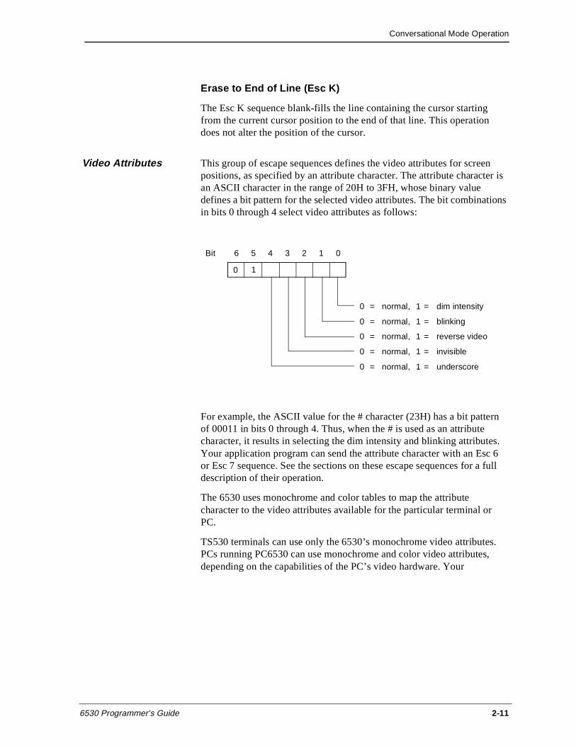
Conversational Mode Operation
6530 Programmer’s Guide 2-11
Erase to End of Line (Esc K)
The Esc K sequence blank-fills the line containing the cursor starting from the current cursor position to the end of that line. This operation does not alter the position of the cursor.
Video Attributes This group of escape sequences defines the video attributes for screen positions, as specified by an attribute character. The attribute character is an ASCII character in the range of 20H to 3FH, whose binary value defines a bit pattern for the selected video attributes. The bit combinations in bits 0 through 4 select video attributes as follows:
For example, the ASCII value for the # character (23H) has a bit pattern of 00011 in bits 0 through 4. Thus, when the # is used as an attribute character, it results in selecting the dim intensity and blinking attributes. Your application program can send the attribute character with an Esc 6 or Esc 7 sequence. See the sections on these escape sequences for a full description of their operation.
The 6530 uses monochrome and color tables to map the attribute character to the video attributes available for the particular terminal or PC.
TS530 terminals can use only the 6530’s monochrome video attributes. PCs running PC6530 can use monochrome and color video attributes, depending on the capabilities of the PC’s video hardware. Your
Bit 6 5 4 3 2 1 0
0 = normal, 1 = dim intensity
0 = normal, 1 = blinking
0 = normal, 1 = reverse video
0 = normal, 1 = invisible
0 = normal, 1 = underscore
0 1
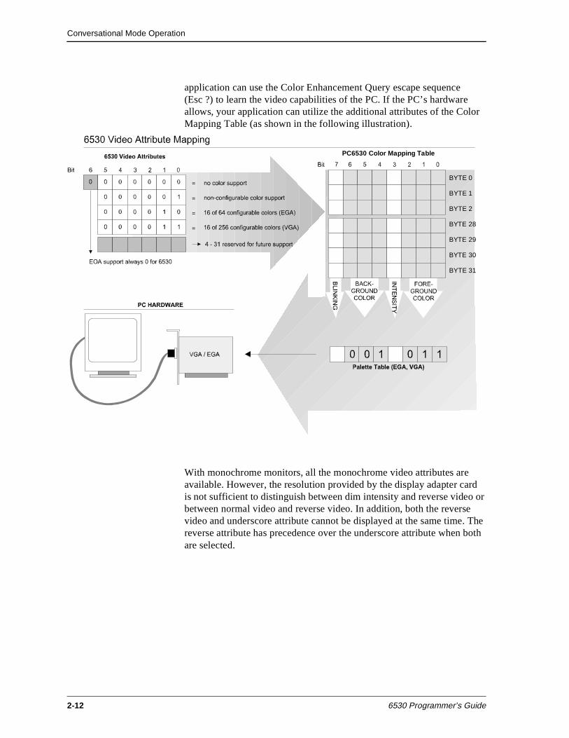
Conversational Mode Operation
2-12 6530 Programmer’s Guide
application can use the Color Enhancement Query escape sequence(Esc ?) to learn the video capabilities of the PC. If the PC’s hardware allows, your application can utilize the additional attributes of the Color Mapping Table (as shown in the following illustration).
With monochrome monitors, all the monochrome video attributes are available. However, the resolution provided by the display adapter card is not sufficient to distinguish between dim intensity and reverse video or between normal video and reverse video. In addition, both the reverse video and underscore attribute cannot be displayed at the same time. The reverse attribute has precedence over the underscore attribute when both are selected.
BYTE 0
BYTE 1
BYTE 2
BYTE 28
BYTE 29
BYTE 30
BYTE 31
PC6530 Color Mapping Table
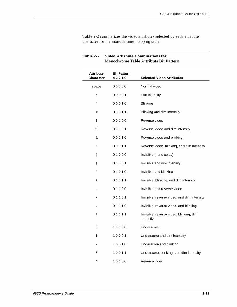
Conversational Mode Operation
6530 Programmer’s Guide 2-13
Table 2-2 summarizes the video attributes selected by each attribute character for the monochrome mapping table.
Table 2-2. Video Attribute Combinations for Monochrome Table Attribute Bit Pattern
Attribute Character
Bit Pattern 4 3 2 1 0 Selected Video Attributes
space 0 0 0 0 0 Normal video
! 0 0 0 0 1 Dim intensity
“ 0 0 0 1 0 Blinking
# 0 0 0 1 1 Blinking and dim intensity
$ 0 0 1 0 0 Reverse video
% 0 0 1 0 1 Reverse video and dim intensity
& 0 0 1 1 0 Reverse video and blinking
’ 0 0 1 1 1 Reverse video, blinking, and dim intensity
( 0 1 0 0 0 Invisible (nondisplay)
) 0 1 0 0 1 Invisible and dim intensity
* 0 1 0 1 0 Invisible and blinking
+ 0 1 0 1 1 Invisible, blinking, and dim intensity
, 0 1 1 0 0 Invisible and reverse video
- 0 1 1 0 1 Invisible, reverse video, and dim intensity
. 0 1 1 1 0 Invisible, reverse video, and blinking
/ 0 1 1 1 1 Invisible, reverse video, blinking, dim intensity
0 1 0 0 0 0 Underscore
1 1 0 0 0 1 Underscore and dim intensity
2 1 0 0 1 0 Underscore and blinking
3 1 0 0 1 1 Underscore, blinking, and dim intensity
4 1 0 1 0 0 Reverse video
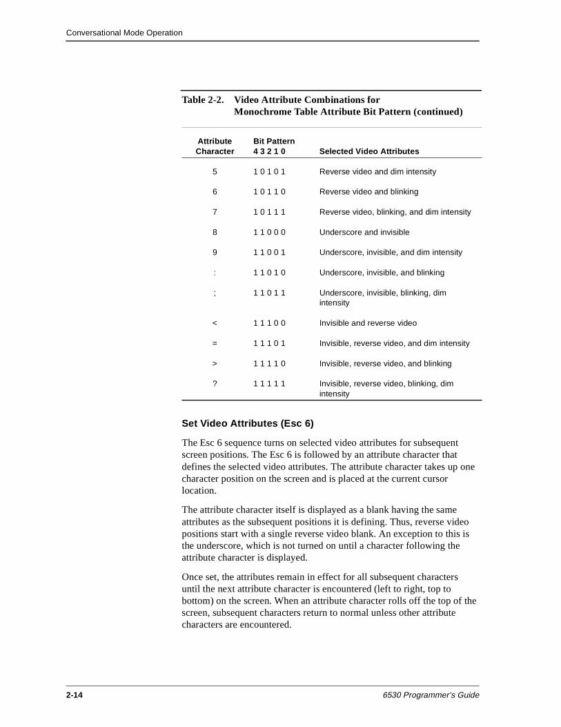
Conversational Mode Operation
2-14 6530 Programmer’s Guide
Set Video Attributes (Esc 6)
The Esc 6 sequence turns on selected video attributes for subsequent screen positions. The Esc 6 is followed by an attribute character that defines the selected video attributes. The attribute character takes up one character position on the screen and is placed at the current cursor location.
The attribute character itself is displayed as a blank having the same attributes as the subsequent positions it is defining. Thus, reverse video positions start with a single reverse video blank. An exception to this is the underscore, which is not turned on until a character following the attribute character is displayed.
Once set, the attributes remain in effect for all subsequent characters until the next attribute character is encountered (left to right, top to bottom) on the screen. When an attribute character rolls off the top of the screen, subsequent characters return to normal unless other attribute characters are encountered.
5 1 0 1 0 1 Reverse video and dim intensity
6 1 0 1 1 0 Reverse video and blinking
7 1 0 1 1 1 Reverse video, blinking, and dim intensity
8 1 1 0 0 0 Underscore and invisible
9 1 1 0 0 1 Underscore, invisible, and dim intensity
: 1 1 0 1 0 Underscore, invisible, and blinking
; 1 1 0 1 1 Underscore, invisible, blinking, dim intensity
< 1 1 1 0 0 Invisible and reverse video
= 1 1 1 0 1 Invisible, reverse video, and dim intensity
> 1 1 1 1 0 Invisible, reverse video, and blinking
? 1 1 1 1 1 Invisible, reverse video, blinking, dim intensity
Table 2-2. Video Attribute Combinations for Monochrome Table Attribute Bit Pattern (continued)
Attribute Character
Bit Pattern 4 3 2 1 0 Selected Video Attributes
Conversational Mode Operation
6530 Programmer’s Guide 2-15
Set Video Prior Condition Register (Esc 7)
The Esc 7 sequence causes the 6530 to load the video prior condition register with the attribute character specified. The attributes selected by the Esc 7 attribute character are in effect for the entire screen, starting at the beginning of the display memory, unless subsequent attribute characters are encountered on the screen.
The Esc 7 attribute character does not take up a character position on the screen. Thus, even though memory is cleared, these attributes remain in effect. After a program reset, system reset, or mode switch, the prior condition register is initialized to normal video.
Color Video Attributes
For PCs with a color monitor and a color video display board, all the video attributes are available except the underscore. How PC6530 maps the underscore attribute depends on whether color mapping is selected. (The user can set color mapping on or off with a PC6530 configuration parameter.) When color mapping is off, the underscore attribute is mapped to blue foreground characters.
When color mapping is on, PC6530 uses the bit pattern of the video attribute character as an index to a color map table. The user can select the colors used in the mapping scheme; otherwise, PC6530 uses default colors. The user-selectable parameters associated with color mapping are:
n Color mapping. Specifies on or off. When on, PC6530 uses a color table to map video attributes. When off, PC6530 uses a monochrome table. (The default for color mapping is off.)
n Normal intensity. Specifies high or low, which affects the actual colors displayed on the screen. Users can select one of 8 colors, but with the intensity setting, 16 colors are actually available in the foreground (only 8 background colors are available). The dim intensity attribute toggles the setting for this parameter. For example, when this parameter is set to low, the dim attribute switches it to high. (The default for normal intensity is high.)
n Normal foreground color. Specifies one of 8 colors used to display characters with the normal attribute. (The default normal foreground color is white.)
n Normal background color. Specifies one of 8 colors used to display the background for the normal attribute. (The default normal background color is blue.)
n Underline foreground color. Specifies one of 8 colors used to display characters with the underscore attribute. (The default underline foreground color is brown.)
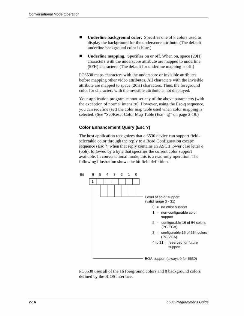
Conversational Mode Operation
2-16 6530 Programmer’s Guide
n Underline background color. Specifies one of 8 colors used to display the background for the underscore attribute. (The default underline background color is blue.)
n Underline mapping. Specifies on or off. When on, space (20H) characters with the underscore attribute are mapped to underline (5FH) characters. (The default for underline mapping is off.)
PC6530 maps characters with the underscore or invisible attributes before mapping other video attributes. All characters with the invisible attribute are mapped to space (20H) characters. Thus, the foreground color for characters with the invisible attribute is not displayed.
Your application program cannot set any of the above parameters (with the exception of normal intensity). However, using the Esc-q sequence, you can redefine (set) the color map table used when color mapping is selected. (See “Set/Reset Color Map Table (Esc - q)” on page 2-19.)
Color Enhancement Query (Esc ?)
The host application recognizes that a 6530 device can support field-selectable color through the reply to a Read Configuration escape sequence (Esc ?) when that reply contains an ASCII lower case letter e (65h), followed by a byte that specifies the current color support available. In conversational mode, this is a read-only operation. The following illustration shows the bit field definition.
PC6530 uses all of the 16 foreground colors and 8 background colors defined by the BIOS interface.
Bit 6 5 4 3 2 1 0
Level of color support (valid range 0 - 31)
0 = no color support
1 = non-configurable color support
2 = configurable 16 of 64 colors(PC EGA)
3 = configurable 16 of 254 colors(PC VGA)
4 to 31= reserved for futuresupport
1
EOA support (always 0 for 6530)
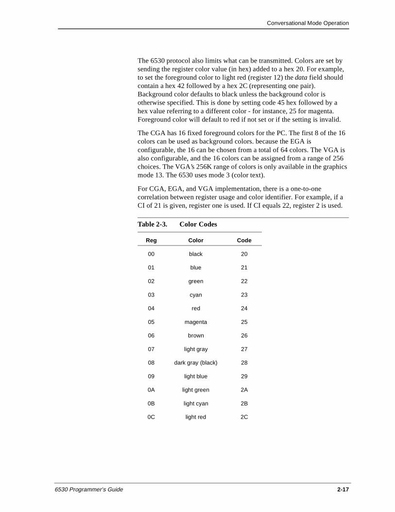
Conversational Mode Operation
6530 Programmer’s Guide 2-17
The 6530 protocol also limits what can be transmitted. Colors are set by sending the register color value (in hex) added to a hex 20. For example, to set the foreground color to light red (register 12) the data field should contain a hex 42 followed by a hex 2C (representing one pair). Background color defaults to black unless the background color is otherwise specified. This is done by setting code 45 hex followed by a hex value referring to a different color - for instance, 25 for magenta. Foreground color will default to red if not set or if the setting is invalid.
The CGA has 16 fixed foreground colors for the PC. The first 8 of the 16 colors can be used as background colors. because the EGA is configurable, the 16 can be chosen from a total of 64 colors. The VGA is also configurable, and the 16 colors can be assigned from a range of 256 choices. The VGA’s 256K range of colors is only available in the graphics mode 13. The 6530 uses mode 3 (color text).
For CGA, EGA, and VGA implementation, there is a one-to-one correlation between register usage and color identifier. For example, if a CI of 21 is given, register one is used. If CI equals 22, register 2 is used.
Table 2-3. Color Codes
Reg Color Code
00 black 20
01 blue 21
02 green 22
03 cyan 23
04 red 24
05 magenta 25
06 brown 26
07 light gray 27
08 dark gray (black) 28
09 light blue 29
0A light green 2A
0B light cyan 2B
0C light red 2C
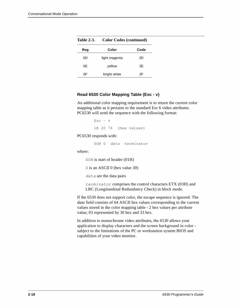
Conversational Mode Operation
2-18 6530 Programmer’s Guide
Read 6530 Color Mapping Table (Esc - v)
An additional color mapping requirement is to return the current color mapping table as it pertains to the standard Esc 6 video attributes. PC6530 will send the sequence with the following format:
Esc - v
1B 20 76 (hex values)
PC6530 responds with:
SOH 0 data terminator
where:
SOH is start of header (01H)
0 is an ASCII 0 (hex value 30)
data are the data pairs
terminator comprises the control characters ETX (03H) and LRC (Longitundinal Redundancy Check) in block mode.
If the 6530 does not support color, the escape sequence is ignored. The data field consists of 64 ASCII hex values corresponding to the current values stored in the color mapping table - 2 hex values per attribute value; 03 represented by 30 hex and 33 hex.
In addition to monochrome video attributes, the 6530 allows your application to display characters and the screen background in color - subject to the limitations of the PC or workstation system BIOS and capabilities of your video monitor.
0D light magenta 2D
0E yellow 2E
0F bright white 2F
Table 2-3. Color Codes (continued)
Reg Color Code
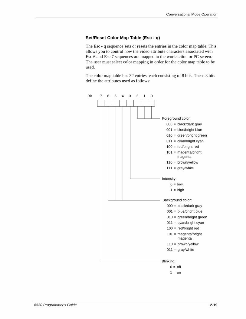
Conversational Mode Operation
6530 Programmer’s Guide 2-19
Set/Reset Color Map Table (Esc - q)
The Esc - q sequence sets or resets the entries in the color map table. This allows you to control how the video attribute characters associated with Esc 6 and Esc 7 sequences are mapped to the workstation or PC screen. The user must select color mapping in order for the color map table to be used.
The color map table has 32 entries, each consisting of 8 bits. These 8 bits define the attributes used as follows:
Bit 7 6 5 4 3 2 1 0
Foreground color:
000 = black/dark gray
001 = blue/bright blue
010 = green/bright green
011 = cyan/bright cyan
100 = red/bright red
101 = magenta/bright magenta
110 = brown/yellow
111 = gray/white
Intensity:
0 = low
1 = high
Background color:
000 = black/dark gray
001 = blue/bright blue
010 = green/bright green
011 = cyan/bright cyan
100 = red/bright red
101 = magenta/bright magenta
110 = brown/yellow
011 = gray/white
Blinking:
0 = off
1 = on
Conversational Mode Operation
2-20 6530 Programmer’s Guide
To specify the 8-bit entries in the table, your application must send pairs of ASCII encoded hexadecimal digits whose binary values represent the 8-bit patterns. For example, the hexadecimal digits 04 represent the following bit pattern:
0000 0100
This bit pattern sets the foreground color to red, the background color to black, the intensity to low, and blinking to off. You can use the 6530 configuration utility for the appropriate operating system to verify your color selection and color bit patterns. See the PC6530 user’s guide for information about the PC6530 configuration utility.
The lower 5 bits from the Esc 6 or Esc 7 attribute character are used as an index into the table, which is 0-based. For example, the # character, with a bit pattern of 00011 in the lower 5 bits, specifies the fourth entry in the table. The hexadecimal digits you set for the fourth table entry defines the actual video attributes displayed when the 6530 receives an Esc 6 # sequence.
The format of the Esc - q escape sequence is as follows:
Esc - pl;[p2];[p3] q pairs of hex digits
where:
p1 is an ASCII digit that specifies whether the color map table is to be set or reset. A value of 0 sets the color map table as defined by the pairs of hexadecimal digits following the escape sequence. A value of 1 resets the color map table to the default mapping scheme, which uses the colors selected in the 6530 initialization file. When the value of p1 is 1, the p2 and p3 parameters are ignored.
p2 is a series of ASCII digits, from 1 to 32, that specify the start-of-index location for the table entries to be set. For example, 1 specifies the first entry in the table. If you omit the parameter or specify a value outside the range of 1 - 32, the default value 1 is used.
p3 is a series of ASCII digits, from 1 to 32, that specify the end-of- index location for the table entries to be set. For example, 32 specifies the last entry in the table. If you omit the parameter or specify a value outside the range of 1 to 32, the default value 32 is used.
Conversational Mode Operation
6530 Programmer’s Guide 2-21
When p1 is set to 0, the escape sequence must be followed by the number of pairs of hexadecimal digits specified by the p2 and p3 range. For example, if p2 is set to 4 and p3 is set to 6, the escape sequence must be followed by three pairs of hexadecimal digits:
Esc - 0;4;6 q 04 40 17
The above sequence sets the fourth, fifth, and sixth entries in the color map table to the bit patterns defined by the hexadecimal digits 04, 40, and 17, respectively. To access those table entries and set the attributes on the screen, your application must send the following escape sequences:
Esc 6 # Sets attributes to fourth table entry (04)
Esc 6 $ Sets attributes to fifth table entry (40)
Esc 6 % Sets attributes to sixth table entry (17)
In the above example, the remaining table entries (1 through 3 and 7 through 32) were not set. Any Esc 6 or Esc 7 attribute character that accesses (indexes) these entries will use the default mapping scheme.
Read Color Mapping Table (Esc - v)
An additional color-mapping requirement is to return the current color mapping table as it pertains to the standard Esc 6 video attributes. The host sends the sequence with the following format:
Esc - v
1B 2D 76 (hex values)
The 6530 responds with:
SOH 0 data CR
where:
SOH is start of header (01H)
0 is an ASCII 0 (hex value 30)
data are the data pairs
CR is the control character (0DH) that terminates the message in conversational mode.
If the PC does not support color, the escape sequence is ignored. The data field consists of 64 ASCII hex values corresponding to the current values stored in the color mapping table - 2 hex values per attribute value; 03 represented by 30 hex and 33 hex.
Conversational Mode Operation
2-22 6530 Programmer’s Guide
Read Color Configuration (Esc - u)
The implementation of the field-selectable color palette register requires the reading and saving of additional color related information. Specifically, the PC6530 must be able to read the contents of the configurable registers before initializing the terminal for PATHWAY usage. The escape sequence has the following format:
Esc - u
1B 2D 75 (hex values)
The 6530 responds with:
SOH 1 cnt data CR
where:
SOH is start of header (01H)
1 is an ASCII 1 (hex value 31)
cnt is the data pair count
data are the data pairs
CR is the control character (0DH) that terminates the message in conversational mode.
If the PC does not support color or uses a CGA display adapter, the escape sequence will be ignored. Only EGA and VGA have programmable color registers. The cnt field will be 2 bytes of the number of color register pairs (ASCII readable hex) following in the data field. The data field will consist of pairs of ASCII hex values corresponding to the current values stored in the color registers. A color register pair will be register number plus register value. These values will be 2 bytes each in ASCII readable hex format. For example, register 12 (hex 0C), which contains the value of 5D will be stored as hex 30, hex 43, hex 35, hex 44. This constitutes one color register pair.
Conversational Mode Operation
6530 Programmer’s Guide 2-23
Set Color Configuration (Esc - t)
Once the host has read the color palette register configuration, it may determine the configuration must be changed. Changing the configuration requires an escape sequence of the following format: an escape, hyphen, 3 parameters separated by semicolons, lowercase t, and the color data information.
Esc - p1;p2;p3 t data
1B 2D p1 3B p2 3b p3 74 data (hex values)
where:
p1 sets (0 - hex 30) or resets (1 - hex 31) the color palette. If you are setting the color palette, use the values defined in data to the range applied by p2 through p3. If you are resetting the color palette, use the values set by the terminal at initialization. If reset, the second and third parameters may be omitted; they are ignored if sent.
p2 is the lower range of palette registers. Values are determined by the configuration (0-15 for EGA or VGA), a maximum of 2 bytes in ASCII decimal readable format. For example, register 9 would be hex 39; register 14 would be hex 31/hex 34.
p3 is the upper range of palette registers. Values are determined by the configuration (0-15 for EGA or VGA), a maximum of 2 bytes in ASCII decimal readable format. As in p2, register 9 would be hex 39; register 14 would be hex 31/hex 34.
data are the valid register values defined by PC documentation for the color requirements for EGA or VGA and other values defined by terminal documentation. These values are 2 bytes each in ASCII hex readable format. For example, a register value of 5E would be represented by hex 35, hex 45; and a register value of 8 would be represented by a hex 30, hex 38.
All data values are stored as ASCII hex values. Parameter values are stored as ASCII decimal values.
Conversational Mode Operation
2-24 6530 Programmer’s Guide
Limitations
Whether implemented with CGA, EGA, or VGA BIOS, the 6530’s Enhanced Color Field control codes can only be invoked to use sixteen colors, regardless of the number of colors available in the BIOS specification. This means:
n When implemented with CGA, the 6530 is capable of controlling all available colors, including the designation of any of the first eight colors as background colors.
n When implemented with an EGA BIOS, a choice of any 16 of the 64 available colors must be made.
n When implemented with VGA BIOS, a choice of any 16 of the 256 colors available must be made. The 6530 uses VGA mode 3 (color text).
Enhanced Color Field control codes are constructed by first identifying whether the setting is for foreground (hex 42) or background (hex 45), then sending the register color value (in hex) added to a hex 20.
For example, to set the foreground color to light red (register 12) the data field should contain a hex 42 (select foreground color) followed by a hex 2C (0C+20H=2CH). To set the background color to magenta (register 05), the data field should contain a hex 45 (select background color) followed by a hex 25 (05+20H=25H).
Default colors are: foreground = red, background = black.
Configuration Values
This group of escape sequences reads or sets values for configuration parameters. These include parameters for terminal or PC operation and parameters for attached devices, such as a printer.
Consult the PC6530 or TS530 user’s guide to determine which configuration parameters are available for you.
Some of the parameters are specified by a code/value pair, where the code identifies the configuration item and the value specifies the selection for the item.
Table 2-4 lists the terminal configuration parameters and shows the code and possible values for each. Table 2-5 on page 2-29 lists the device configuration parameters and shows the code and possible values for each. Other parameters are specified by string values, which vary in length.
The Read Terminal Configuration sequence (Esc ?) causes the 6530 to transmit the current values for the terminal configuration parameters to the host.
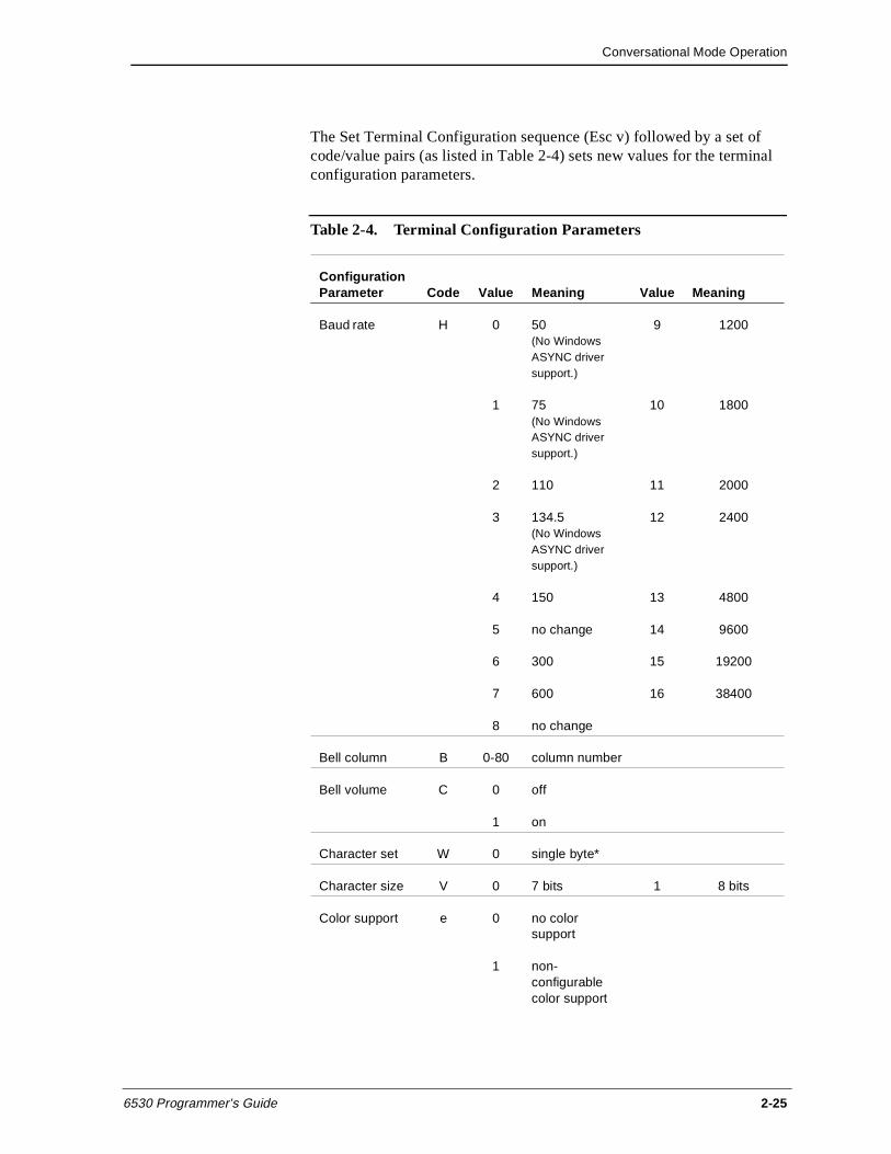
Conversational Mode Operation
6530 Programmer’s Guide 2-25
The Set Terminal Configuration sequence (Esc v) followed by a set of code/value pairs (as listed in Table 2-4) sets new values for the terminal configuration parameters.
Table 2-4. Terminal Configuration Parameters
Configuration Parameter Code Value Meaning Value Meaning
Baud rate H 0 50 (No Windows ASYNC driver support.)
9 1200
1 75 (No Windows ASYNC driver support.)
10 1800
2 110 11 2000
3 134.5 (No Windows ASYNC driver support.)
12 2400
4 150 13 4800
5 no change 14 9600
6 300 15 19200
7 600 16 38400
8 no change
Bell column B 0-80 column number
Bell volume C 0 off
1 on
Character set W 0 single byte*
Character size V 0 7 bits 1 8 bits
Color support e 0 no color support
1 non-configurable color support
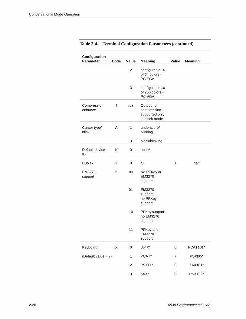
Conversational Mode Operation
2-26 6530 Programmer’s Guide
2 configurable 16 of 64 colors - PC EGA
3 configurable 16 of 256 colors - PC VGA
Compression enhance
f n/a Outbound compression supported only in block mode
Cursor type/blink
A 1 underscore/ blinking
3 block/blinking
Default device ID
K 0 none*
Duplex J 0 full 1 half
EM3270 support
h 00 No PFKey or EM3270 support
01 EM3270 support; no PFKey support
10 PFKey support; no EM3270 support
11 PFKey and EM3270 support
Keyboard X 0 654X* 6 PCAT101*
(Default value = 7) 1 PCAT* 7 PSXl05*
2 PSXl0l* 8 6AX101*
3 6AX* 9 PSX102*
Table 2-4. Terminal Configuration Parameters (continued)
Configuration Parameter Code Value Meaning Value Meaning
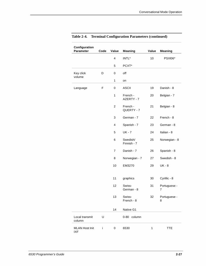
Conversational Mode Operation
6530 Programmer’s Guide 2-27
4 INTL* 10 PSXl06*
5 PCXT*
Key click volume
D 0 off
1 on
Language F 0 ASCII 19 Danish - 8
1 French - AZERTY - 7
20 Belgian - 7
2 French - QUERTY - 7
21 Belgian - 8
3 German - 7 22 French - 8
4 Spanish - 7 23 German - 8
5 UK - 7 24 Italian - 8
6 Swedish/Finnish - 7
25 Norwegian - 8
7 Danish - 7 26 Spanish - 8
8 Norwegian - 7 27 Swedish - 8
10 EM3270 29 UK - 8
11 graphics 30 Cyrillic - 8
12 Swiss-German - 8
31 Portuguese - 7
13 Swiss-French - 8
32 Portuguese - 8
14 Native G1
Local transmit column
U 0-80 column
MLAN Host Init IXF
i 0 6530 1 TTE
Table 2-4. Terminal Configuration Parameters (continued)
Configuration Parameter Code Value Meaning Value Meaning
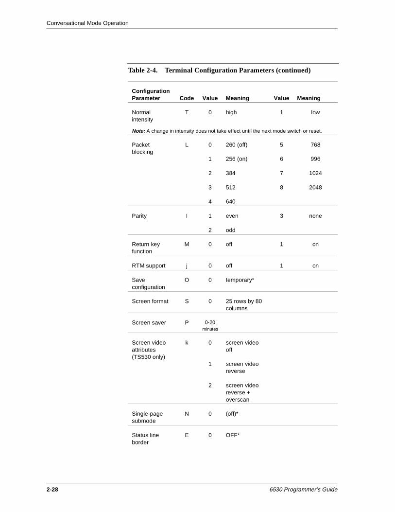
Conversational Mode Operation
2-28 6530 Programmer’s Guide
Normal intensity
T 0 high 1 low
Note: A change in intensity does not take effect until the next mode switch or reset.
Packet blocking
L 0 260 (off) 5 768
1 256 (on) 6 996
2 384 7 1024
3 512 8 2048
4 640
Parity I 1 even 3 none
2 odd
Return key function
M 0 off 1 on
RTM support j 0 off 1 on
Save configuration
O 0 temporary*
Screen format S 0 25 rows by 80 columns
Screen saver P 0-20 minutes
Screen video attributes (TS530 only)
k 0 screen video off
1 screen video reverse
2 screen video reverse + overscan
Single-page submode
N 0 (off)*
Status line border
E 0 OFF*
Table 2-4. Terminal Configuration Parameters (continued)
Configuration Parameter Code Value Meaning Value Meaning
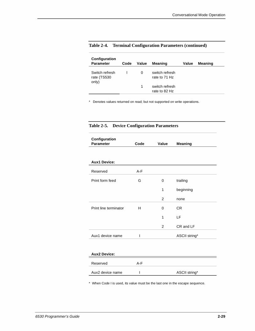
Conversational Mode Operation
6530 Programmer’s Guide 2-29
* Denotes values returned on read; but not supported on write operations.
* When Code I is used, its value must be the last one in the escape sequence.
Switch refresh rate (TS530 only)
l 0 switch refresh rate to 71 Hz
1 switch refresh rate to 82 Hz
Table 2-4. Terminal Configuration Parameters (continued)
Configuration Parameter Code Value Meaning Value Meaning
Table 2-5. Device Configuration Parameters
Configuration Parameter Code Value Meaning
Aux1 Device:
Reserved A-F
Print form feed G 0 trailing
1 beginning
2 none
Print line terminator H 0 CR
1 LF
2 CR and LF
Aux1 device name I ASCII string*
Aux2 Device:
Reserved A-F
Aux2 device name I ASCII string*
Conversational Mode Operation
2-30 6530 Programmer’s Guide
Read Terminal Configuration (Esc ?)
The Esc ? sequence causes the 6530 to transmit the current values for the terminal configuration parameters to the host. The message returned has the following general format:
SOH ! code value [code value] ... CR
where:
SOH is a control character (01H) that acts as a start of header for messages returned to the host.
The exclamation point (!) identifies this message as a configuration message.
code is an ASCII character that uniquely identifies a configuration parameter. (See Table 2-4 on page 2-25.) For example, the code A specifies the cursor type.
value is a decimal number that specifies a value for the preceding configuration parameter. (See Table 2-4 on page 2-25.) For example, a 1 value for the cursor type specifies a blinking underscore.
CR is a control character (0DH) that terminates the message.
A code/value pair is returned for each configuration item. The code/value pair equals three bytes unless the value is 100 or greater. In that case, the code/value pair equals four bytes. When the value is less than two digits, a space character (20H) is returned between the code and value. For example:
A1 is returned when the cursor type is set to underscore/blinking.
H15 is returned when the baud rate is set to 19200.
Set Terminal Configuration (Esc v)
The Esc v sequence sets new values for the terminal configuration parameters. The Esc v code is followed by a set of code/value pairs (as shown in Table 2-4 on page 2-25) and terminated by a CR character (0DH). You can set new values for any subset of the configuration parameters. For example, the following escape sequence sets values for the cursor type and the bell column:
Esc v A0 B72 CR
If a value is outside the allowable range for the parameter, the new setting is ignored.
Conversational Mode Operation
6530 Programmer’s Guide 2-31
Read I/O Device Configuration (Esc y)
The Esc y sequence causes the 6530 to transmit the current values for the Auxl and Aux2 device configuration parameters to the host. The Esc y must be followed by a T and a decimal number that identifies the device (2 for the Auxl device and 3 for the Aux2 device). For example:
Esc y T2
The message returned has the following general format:
SOH ! code value [code value] ... CR
where:
SOH is a control character (01H) that acts as a start of header for messages returned to the host.
The exclamation point (!) identifies this message as a configuration message.
code is an ASCII character that uniquely identifies a configuration parameter. (See Table 2-4 on page 2-25.)
value is either a decimal number or string that specifies a value for the preceding configuration parameter. (See Table 2-4 on page 2-25.)
CR is a control character (0DH) that terminates the message.
A code/value pair is returned for each configuration item. Each code/value pair equals three bytes.
Set I/O Device Configuration (Esc x)
The Esc x sequence sets new configuration values for the Aux 1 or Aux2 devices. The escape sequence has the following general format:
Esc x T device code value [code value] ... CR
where:
The T is required before device, which specifies the type of device. This must be either 2 for the Auxl device or 3 for the Aux2 device.
code is an ASCII character that uniquely identifies a configuration parameter. (See Table 2-4 on page 2-25.)
value is either a decimal number or string that specifies a value for the preceding configuration parameter. (See Table 2-4 on page 2-25.)
CR is a control character (0DH) that terminates the sequence.
Conversational Mode Operation
2-32 6530 Programmer’s Guide
The following example sets the form feed for a printer associated with the Auxl device:
Esc x T2 G1 CR
Read String Configuration Parameter (Esc - d)
The Esc - d sequence causes the 6530 to transmit the current values for the configuration parameters with string values. The escape sequence has the following format:
Esc - pn d
where:
pn is an ASCII digit from 0 through 7 that specifies the parameter(s) to be read as follows:
0 = read all seven string parameters
1 = read window name parameter (string value up to 26 characters)
2 = read resource name parameter (string value up to 34 characters)
3 = read host name parameter (string value up to 8 characters)
4 = read start up string parameter (string value up to 128 characters)
5 = read transmit line parameter (string value up to 80 characters)
6 = read device name parameter (string value up to 8 characters)
7 = read session name parameter (string value up to 16 characters)
If the pn parameter is missing or greater than 7, all seven parameter values are returned. The message returned has the following general format:
SOH ( string DC2 [string DC2] ... CR
where:
SOH is a control character (01H) that acts as a start of header for messages returned to the host.
The left parenthesis ( ( ) identifies this message as a string value configuration message.
string is the ASCII character string value for the parameter(s) read. When all seven parameters are returned, they are returned in the order specified by pn as listed above.
DC2 is a control character (12H) that acts as a delimiter for the string values.
Conversational Mode Operation
6530 Programmer’s Guide 2-33
CR is a control character (0DH) that terminates the message.
Set String Configuration Parameter (Esc - c)
The Esc - c sequence sets new values for configuration parameters with string values. The escape sequence has the following format:
Esc - pn c string DC2 [string DC2] ... CR
where:
pn is an ASCII digit from 0 through 7 that specifies the parameter(s) to be set. These are the same as the pn values for the Esc - d sequence. If the pn parameter is missing or greater than 7, values for all seven parameters are expected following the c.
string is the ASCII character string value for the parameter(s) to be set. When all seven parameters are set, their string values must be listed in the order specified by pn. The 6530 truncates any string values that exceed the maximum length allowed for that parameter.
DC2 is a control character (l2H) that acts as a delimiter for the string values.
CR is a control character (0DH) that terminates the message.
Read VTLAUNCH 6530 Configuration Parameter ( Esc - g )
The Esc - g escape sequence provides a mechanism for the host to identify the connected 6530 in Virtual Terminal Launch (VTLAUNCH). Host programs that support various 6530s can use this information to provide extended support for those devices.
The Esc - g sequence causes the 6530 to transmit the current string values of its supported configuration parameters. Only parameters 2 (terminal type) and 3 (operating system version) are supported by the 6530.
A syntax error in the escape sequence causes the 6530 to ignore the sequence and return no response.
The Escape sequence has the following format:
Esc - pn g
Conversational Mode Operation
2-34 6530 Programmer’s Guide
where:
pn is the parameter number (an ASCII numeric character)
0 = all 6530 parameters in order 1-6
2 = 6530 type
3 = operating system version
The return message has the following format:
SOH ( string DC2 [string DC2]... CR
where:
SOH is start of header (01H)
( is left parenthesis (28H)
string is the ASCII character string value for the parameter(s) to be set. When all seven parameters are set, their string values must be listed in the order specified by pn. The 6530 truncates any string values that exceed the maximum length allowed for that parameter.
DC2 is a control character (12H) that acts as a delimiter for the string values.
CR is a control character (0DH) that terminates the message.
Table 2-6. 6530 responses to Read VTLAUNCH Configuration Parameter
pn Response
0 SOH ( str DC2 str2 DC2 str3 DC2 str DC2 str DC2 str DC2 CR
1 SOH ( str DC2 CR
2 SOH ( str2 DC2 CR
3 SOH ( str3 DC2 CR
4 SOH ( str DC2 CR
5 SOH ( str DC2 CR
6 SOH ( str DC2 CR
Conversational Mode Operation
6530 Programmer’s Guide 2-35
where:
pn is an ASCII digit from 0 through 6 that specifies the parameter(s) to be set
str = omitted string (zero length)
str2 = "PC6530" for PC6530
str3 = "DOS5.0" for MS-DOS version 5.0= "DOS4.0" for MS-DOS version 4.0= "DOS3.3" for MS-DOS version 3.3
The MS-DOS string returned for str3 is determined by the result of a call to MS-DOS INT 21 Function 30H.
RTM Support The 6530 supports Response Time Measurement (RTM): collecting response time statistics, accepting commands to set up RTM collection parameters, and accepting commands that solicit a response containing the RTM data collected.
Response Time Measurement is implemented by using a configurable number of counters (buckets) which count the number of times that measured response intervals fall within configurable time range boundaries (bucket boundaries) associated with each counter.
The response interval is the measured length of time between the start and stop timing events which are configurable as either:
the press of a function key (start) and the receipt of the first resulting character from the host (stop),
or
the press of a function key (start) and the receipt of the keyboard unlock command (stop).
The time measurement is reported to the nearest 100 milliseconds and is accurate within 10 percent or less.
Bucket boundaries consist of a lower boundary and upper boundary, specified in centiseconds. The count held in the bucket is incremented by one when a response interval measurement falls within the bucket boundaries.
The configured number of buckets will contiguously cover the time range from 0 to infinity. Buckets are actually defined by specifying one or more partitions in that range, rather than explicitly specifying the start and end value for each bucket.
Conversational Mode Operation
2-36 6530 Programmer’s Guide
For example, specifying one partition at 100 centiseconds causes two buckets to be created - one that counts the occurrence of response intervals in the range of 0 to 100 centiseconds and a second bucket that counts the occurrence of response intervals greater than 100 centiseconds.
RTM recording of response intervals is enabled on entry to block mode and also each time the RTM Controls are reset. The RTM Controls for terminals include definition of the response interval start/stop events, the number of buckets, and the bucket boundaries (specified as partitions).
The default RTM control settings are:
RTM response interval start/stop events are any function key press (start) and the receipt of the keyboard unlock command (stop).
The number of buckets is five.
Five buckets are configured by setting four bucket partitions at 200 csec, 400 csec, 1000 csec, 2000 csec, which results in the following buckets:
Bucket: B1 B2 B3 B4 B5
Bucket boundaries: 0....2s....4s....10s....20s....infinity
The 6530 also supports RTM Definite Response. Definite Response enables the host to elicit an expected 6530 response and measure the time between the request and the response. The facility for this is the Simulate Function Key (Esc d) escape sequence. See “Simulate Function Key (Esc d)” on page 2-49 for escape sequence format information.
RTM Control (Esc - i)
The Esc - i sequence configures the Response Time Measurement Controls.
The format of the escape sequence is:
Esc - parameters i
where:
- = minus sign (2DH)
i = lowercase i (69H)
parameters = ASCII numeric character strings, in the formatp1[;p2[;pn]...]
Conversational Mode Operation
6530 Programmer’s Guide 2-37
p1: Response Interval Start/Stop Events
1 = Any function key press / keyboard unlock command receipt
2 = Any function key press / any host data receipt
p2: Number of Buckets
1 to 10
A value of 1 is valid. It is not followed by a bucket partition because it defines a bucket with boundaries from 0 to infinity, which counts every response.
pn: Bucket Partition (centisec)
pn occurs number of buckets - 1 times. The ASCII numeric string specifying each bucket partition may not exceed 5 digits and may not exceed a value of 65535.
Here is an example escape sequence that sets the controls to the default values detailed above (Esc = escape character):
Esc-1;5;200;400;1000;2000i
No response is expected from the terminal. If there is a violation of syntax or range, the terminal ignores the escape sequence.
RTM Data Upload (Esc - j)
The Esc - j sequence causes an upload of RTM data to the host. The request from the host is tagged with a 32 bit ID which the host breaks into 4 bytes, representing each byte with an ASCII numeric string in the range of 0 to 255. The ASCII numeric representation of the 4 bytes is returned to the host in the same byte order, along with the RTM bucket data.
If there is a violation of syntax or range in the host request, the terminal ignores the escape sequence.
The format of the escape sequence is:
Esc - ID j
where:
ID = p1;p2;p3;p4
p1, p2, p3, and p4 are ASCII numeric string representations of an unsigned 8 bit value in the range of 0 to 255.
The data uploaded to the host is in the format:
ID;B1[;Bn]...];t;ov CR
Conversational Mode Operation
2-38 6530 Programmer’s Guide
where:
ID = p1;p2;p3;p4
p1, p2, p3, and p4 are ASCII numeric string representations of an unsigned 8 bit value in the range of 0 to 255.
B1,Bn = An ASCII numeric string indicating the number of response intervals that fell into the range of the particular bucket.
B1 is always be returned.
Bn represents occurrences of buckets 2 through 10, if these are configured.
t = An ASCII numeric string that indicates total elapsed time in centiseconds. The maximum value is 4294967295.
ov = An ASCII 1 to indicate that one of the buckets has reached the maximum count, or an ASCII 0 to indicate that no bucket has reached the maximum value of 65535.
CR is a control character (0DH) that terminates the message.
Status Information This group of escape sequences provides status information about the 6530, the Auxl and Aux2 devices, and current workstation or PC directory.
Read Terminal Status (Esc ^)
The Esc ^ sequence causes the 6530 to transmit the status of the Aux1 or Aux2 device and the major revision level of the 6530 to the host. This returned status message has the following general format:
SOH ? status term-id maj-rev-level CR
where:
SOH is a control character (01H) that acts as a start of header for messages returned to the host.
The question mark (?) identifies this message as a status message.
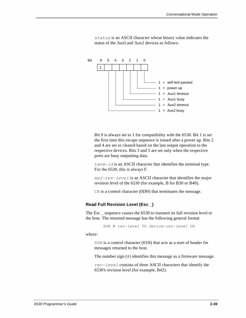
Conversational Mode Operation
6530 Programmer’s Guide 2-39
status is an ASCII character whose binary value indicates the status of the Auxl and Aux2 devices as follows:
Bit 0 is always set to 1 for compatibility with the 6530. Bit 1 is set the first time this escape sequence is issued after a power up. Bits 2 and 4 are set or cleared based on the last output operation to the respective devices. Bits 3 and 5 are set only when the respective ports are busy outputting data.
term-id is an ASCII character that identifies the terminal type. For the 6530, this is always F.
maj-rev-level is an ASCII character that identifies the major revision level of the 6530 (for example, B for B30 or B40).
CR is a control character (0DH) that terminates the message.
Read Full Revision Level (Esc _)
The Esc _ sequence causes the 6530 to transmit its full revision level to the host. The returned message has the following general format
SOH # rev-level T0 device-rev-level CR
where:
SOH is a control character (01H) that acts as a start of header for messages returned to the host.
The number sign (#) identifies this message as a firmware message.
rev-level consists of three ASCII characters that identify the 6530’s revision level (for example, B42).
Bit 6 5 4 3 2 1 0
1 = self test passed
1 = power up
1 = Aux1 timeout
1 = Aux1 busy
1 = Aux2 timeout
1 = Aux2 busy
1
Conversational Mode Operation
2-40 6530 Programmer’s Guide
T0 and device-rev-level are returned for compatibility with 6530 terminal options. device-rev-level is always the same as rev-level.
CR is a control character (0DH) that terminates the message.
Get Machine Name (Esc - e)
The Esc - e sequence is valid only for a workstation or PC that is running under MS-DOS on a Multilan connection. The escape sequence causes the 6530 to transmit the machine (LAN) name currently set for the workstation or PC. The returned message has the following format:
SOH & string CR
where:
SOH is a control character (01H) that acts as a start of header for messages returned to the host.
The ampersand (&) identifies this message as a machine name message.
string is the ASCII character string value for the machine name setting. If no characters are returned, the machine name has not been set at the workstation or PC.
CR is a control character (0DH) that terminates the message.
Get Current Directory and Redirection Information (Esc - f)
The Esc - f sequence causes the 6530 to transmit the pathname of the current directory for a specified drive of the workstation or PC. The escape sequence is valid only for a workstation or PC that is running under MS-DOS on a Multilan connection. If the workstation or PC is on a Multilan connection and the specified drive is on the network redirection list, the 6530 also returns the redirection list entry for the drive. The escape sequence has the following format:
Esc - f drive
where:
drive is an ASCII character in the range of @ (40H) through Z (5AH) that specifies the workstation or PC drive. The @ character (40H) specifies the current drive.
The returned message has the following format:
SOH ’ drive DC2 string1 DC2 string2 CR
Conversational Mode Operation
6530 Programmer’s Guide 2-41
where:
SOH is a control character (01H) that acts as a start of header for messages returned to the host.
The apostrophe (’) identifies this message as a directory and redirection message.
drive is an ASCII character in the range of 41H through 5AH that specifies the current default drive of the workstation or PC.
DC2 is a control character (l2H) used to delimit the following string values.
string1 is an ASCII string of 1 or more characters that represents the full pathname (starting from the root and including the backslash) of the current directory for the specified drive. If the length of stringl is 0, the 6530 received an operating system error when retrieving the information.
string2 is an ASCII string of 1 or more characters that represents the network redirection entry for the specified drive. If the length of string2 is 0, either the 6530 received an operating system error when retrieving the information or the specified drive is not in the network redirection table.
CR is a control character (0DH) that terminates the message.
Device Control This group of escape sequences performs operations on devices attached to the workstation or PC.
Print Screen (Esc 0)
The Esc 0 sequence transfers the contents of the display screen (except for the message/status line) to the workstation or PC device specified by the Auxl parameter. The 6530 reserves a one-page print buffer to save the data to be printed. When the print function is invoked, the screen data is moved into the print buffer. Because this is saved in a separate area of memory, the keyboard need not be locked while the data is printing.
Print requests from your application always take precedence over local requests by the user. If your application requests a print operation while one is in process, the 6530 performs the following:
Conversational Mode Operation
2-42 6530 Programmer’s Guide
n Aborts the current print operation; displays an error message (PRINT ABORT) in the error line and sounds the bell.
n Sends a carriage return (CR), followed by a form feed (FF), to the printer interface.
n Initiates the application’s print request.
This abort can be avoided if your application observes the following sequence:
1. Lock the keyboard (Esc c sequence).
2. Check the status for a print in process (Esc ^ sequence).
3. If no print is in process, send the new print request (Esc 0 sequence).
4. Unlock the keyboard (Esc b sequence).
A program reset, system reset, or mode switch also aborts a print operation in process.
If the user requests a print operation while one is in process, this second print request is ignored. Also, the error message PRINT BUSY is displayed in the error line and the bell is sounded.
If a video attribute is encountered while transmitting text to the Auxl device, a space character (20H) is substituted in the print stream for the attribute character. If the video attribute includes invisible, space characters (20H) are substituted in the print stream for subsequent text. If the video attribute includes underscore and the Aux1 line end parameter is not set to CR, subsequent text sent to the printer is followed by a CR (0DH) and a line with underscore characters (_, 5FH) for each character position that is to be underscored. When the Aux1 line end parameter is set to CR, the underscore attribute is ignored.
Write to Aux1 or Aux2 Device (Esc - O)
The Esc - O sequence outputs host-generated data to the workstation or PC device specified by either the Aux1 or Aux2 parameter. All text following the escape sequence is written verbatim to the selected device. The text sequence can include any character code that is passable by conversational mode and the communications protocol used. The text sequence is normally terminated by a DC2 control character (12H). You can specify a different terminating character if necessary.
The Esc - O sequence has the following general format:
Esc - device ; terminator O
Conversational Mode Operation
6530 Programmer’s Guide 2-43
where:
device is a decimal number that specifies which device parameter is used. This must be either 1 for the Auxl device or 2 for the Aux2 device. If any other value is specified or the parameter is omitted, the 6530 assumes the Aux1 device.
terminator is a decimal number in the range of 3 through 127 that specifies a terminating character you have chosen to represent the end-of-text sequence. The number represents the decimal value of the ASCII character code. For example, the number 19 specifies a DC3 control character (l3H). If this parameter is omitted, a DC2 control character (12H) is assumed.
Note Make sure the data passed to the device is terminated properly. Otherwise, all data from your application, including control codes and escape sequences will continue to be passed to the device and will not be processed by the 6530.
Write to File or Device Name (Esc { )
The Esc { sequence allows your application to open, write to, then close an operating system file or device name.
You cannot check the status of the operation performed with this escape sequence. It is recommended that you use the Esc } sequence to perform both write and read operations on a device. The format of the escape sequence is as follows:
Esc { “ device” opcode SPACE data CR
where:
device is the operating system file or device name to which you are performing the write operation. Note that the device name must be enclosed in quotes.
opcode is one of the following ASCII hexadecimal pairs that specifies the operation to be performed. These correspond to the same codes used to make operating system calls:
3C = create 40 = write
3D = open 42 = delete
3E = close 43 = seek EOF
Conversational Mode Operation
2-44 6530 Programmer’s Guide
SPACE represents a space (H20), which must precede the data.
data is the data to be written to the device when a write (40) operation is specified. A space must precede the data. The data can be:
• A mode switch sequence that specifies the type of data (Esc a for ASCII data or Esc b for binary data) to be sent on a subsequent write.
• ASCII characters in the range of 20H to 7E.
• Binary data specified by pairs of ASCII hexadecimal pairs that represent single characters in the range of 00H to FFH.
CR is a control character (0DH) that terminates the escape sequence.
See the programmer’s guide for your workstation’s operating system for more information about writing to a file or device.
Write/Read to File or Device name (Esc } )
The Esc } sequence allows your application to perform I/O operations on an operating system file or device name. The format of the escape sequence is as follows:
Esc } “ device” operation SPACE data CR
where:
device is the operating system file or device name to which you are performing the write/read operation. Note that the device name must be enclosed in quotes.
operation is one of the following ASCII hexadecimal pairs that specifies the function to be performed. These correspond to the same codes used to make operating system calls:
The write/read operation is a composite of an operating system write function followed by a read. The read status information, however, is returned in the message described below.
3C = create 40 = write
3D = open 43 = seek EOF
3E = close 42 = delete
3F = read
Conversational Mode Operation
6530 Programmer’s Guide 2-45
SPACE represents a space (H20), which must precede the data.
data is the data to be written to the device when a write (40) or write/read (7E) operation is specified. A space must precede the data. The data can be:
• A mode switch sequence that specifies the type of data (Esc a for ASCII data or Esc b for binary data) to be sent on a subsequent write.
• ASCII characters in the range of 20H to 7E.
• Binary data specified by pairs of ASCII hexadecimal pairs that represent single characters in the specified range of 00H to FFH.
CR is a control character (0DH) that terminates the escape sequence.
On read or write/read operations, the escape sequence returns a message with the following format:
SOH % status data CR
where:
SOH is a control character (01H) that acts as a start of header for messages returned to the host.
The per cent sign (%) identifies this message as an operating system read message.
status is one of the following ASCII characters that indicates the status of the operation:
space (20H) = operation successful
“ (22H) = file not found
$ (24H) = too many files open
% (25H) = access denied
& (26H) = invalid handle
, (2CH) = invalid access
{ (7BH) = invalid opcode
| (7CH) = invalid device
} (7DH) = device not open
~ (7EH) = invalid format
Conversational Mode Operation
2-46 6530 Programmer’s Guide
data is the data read from the device when a read operation is specified. Only 255 bytes of text data can be returned at one time. To perform sequential read operations, your application should continue issuing the Esc } sequence until 0 bytes are returned in data.
CR is a control character (0DH) that terminates the message.
See the appropriate programmer’s guide for your operating system for more information about performing I/O operations on a device driver.
Load and Execute an Operating System Program (Esc - V)
The Esc - V sequence allows your application to start an MS-DOS program (child process) from the 6530. The user must set the EXEC function parameter to ON to allow this escape sequence. Refer to the User’s manual for PCT/PC6530 for further information before disarming this safety mechanism. The escape sequence has the following format:
Esc - V filename [parameters] CR
where:
filename is the file name of the operating system program to be started. Only the file name (with the .exe or .com extension) should be specified - not the path. This means the user must have the path set correctly for the program file.
parameters specify the command line parameters (if any) required by the program to be started.
This escape sequence is equivalent to the operating system execute process function. Refer to the programmer's guide for your operating system for more information.
Note When you execute this process, communications between the host and the 6530 are discontinued until the process has completed.
Conversational Mode Operation
6530 Programmer’s Guide 2-47
Report Exec Return Code (Esc - W)
The Esc - W sequence returns the Exec function return code, as well as the return and exit codes for the child process started by an Esc - V sequence. The returned message has the following format:
SOH $ execcode proccodel proccode2 proccode3 CR
where:
SOH is a control character (01H) that acts as a start of header for messages returned to the host.
The dollar sign ($) identifies this message as an operating system return code message.
execcode is one of the following ASCII characters that specifies the Exec function return code:
space (20H) = operation successful, OK to get child exit code
! 21H) = invalid function
“ (22H) = file not found
# (23H) = path not found
% (25H) = access denied
( (28H) = not enough memory
* (2AH) = bad environment
+ (2BH) = bad format
| (7CH) = reserved for IXF PC id
} (7DH) = program file name not found
~ (7EH) = security violation (EXEC function parameter not set to ON)
Conversational Mode Operation
2-48 6530 Programmer’s Guide
proccode1 is one of the following ASCII characters that specifies the child process return code:
proccode2 and proccode3 are ASCII characters in the range of 20H to 2FH whose ASCII codes offset by 1FH represent the nibble values for the child process exit code. The most significant nibble is represented by proccode2, and the least significant nibble is represented by proccode3.
CR is a control character (0DH) that terminates the message.
See the programmer’s guide for your operating system for more information.
Disconnect Modem (Esc f)
The Esc f sequence forces the Data Terminal Ready line (CD) into a low state for three seconds. This causes most modems to disconnect and terminate the connection.
General Operations This group of control codes and escape sequences performs a variety of terminal functions.
Bell (BEL)
The BEL control character (07H) causes the 6530 to sound an audible alarm. It is typically used to alert the user of some action, such as an error.
Delay One Second (Esc @)
The Esc @ sequence causes the 6530 to stop processing the input stream for approximately one second. At the end of the delay, normal processing continues.
space (20H) = terminate/abort (normal termination)
! (21H) = Shift-break
“ (22H) = fatal error (critical device error)
# (23H) = terminate and stay resident (KEEP process)
Conversational Mode Operation
6530 Programmer’s Guide 2-49
Unlock Keyboard (Esc b)
The Esc b sequence unlocks the keyboard and erases the KBD LOCKED phrase in the status line.
Lock Keyboard (Esc c)
The Esc c sequence locks the keyboard and displays the phrase KBD LOCKED in the status line. When the keyboard is locked, the cursor is no longer displayed and all keys (except Caps Lock, Num Lock, Ctrl-Scroll Lock, Ctrl-End, Ctrl-Alt-Del, Ctrl-Backspace, and Alt-Backspace) are disabled.
Simulate Function Key (Esc d)
The Esc d sequence simulates the depression of a function key. After receiving an Esc d sequence, the 6530 locks the keyboard and, on the next read request, transmits a function key message to the host. The Esc d is followed by a single character that designates the keycode for the simulated function key. For example, if your application sends an Esc d X sequence, the 6530 generates the following message:
SOH X cursor CR
See “Function Keys” on page 2-51 for an explanation of the message format.
Write to Message Field (Esc o)
The Esc o sequence allows your application program to write text into the message field of the message/status line. (See “Message/Status Line” on page 1-2 for a discussion of the message/status line format). The Esc o code is followed by the text to be displayed, and the sequence is terminated by a CR control character (0DH). For example, the following sequence writes the phrase SELECT OPTION into the message fields
Esc o SELECT OPTION CR
The 6530 clears existing messages before writing the new text. Thus, to simply clear the message field, you can send:
Esc o CR
The message can also be assigned video attributes (blank, reverse video, etc.) by embedding Esc 6 sequences within the text.
Conversational Mode Operation
2-50 6530 Programmer’s Guide
Reinitialize (Esc q)
The Esc q sequence executes an initialization sequence similar to that executed upon entering block mode. The exceptions to this are as follows:
n Page 1 is blank filled (rather than containing the screen text from conversational mode).
n The communications line is not reinitialized.
Define Enter Key Function (Esc u)
The Esc u sequence allows you to modify the characters that are generated when the Enter key is pressed. The format for the escape sequence is as follows:
Esc u count string
where:
count is an ASCII character whose code, offset by 20H, indicates the length in bytes of string.
string is any character string of up to 8 characters. This is the character string that will be generated when the RETURN key is pressed. All characters are valid except for NUL (00H) and ENQ (05H). To generate control characters, the ASCII code for the control character must be sent in the escape sequence.
In conversational mode, the power-on sequence initializes the RETURN key to generate a CR (0DH) character. The following example causes the RETURN key to generate a CR as well as a LF (0AH) character and a colon (:) prompt:
Esc u # CR LF :
Terminate Remote 6530 Operation (Esc - z)
The Esc - z sequence allows you to control 6530 remote termination, and allows you to pass error-level information up to the MS-DOS system. This makes it possible to execute programs from batch files that are too large to “spawn off” and keep 6530 resident. On receipt of this escape sequence, the 6530 terminates execution through the same logic as if the user had pressed the Ctrl-End key sequence. The parameter p is an ASCII decimal value to be passed up as the exit error-level. This can be checked in MS-DOS batch files to control execution of that batch file. The format for the sequence is as follows:
Conversational Mode Operation
6530 Programmer’s Guide 2-51
Esc - p1 z
1B 2D p1 7A (hex values)
where:
p1 is the exit error-level (an ASCII decimal value)
Execute Self Test (Esc z)
This command sequence is used at the factory to run self-tests on terminals (not terminal emulators).
Shift Out to G1 Character Set (S0)
The S0 control character (0EH) shifts the 6530 to the G1 character set. Thus, graphics characters in the G1 set are displayed on the screen. (The G1 set is the same as the alternate character set supported on the workstation or PC.)
The S0 character is interpreted independently of the current state of any escape sequence. Only graphics characters sent to the display are affected. Control characters within escape sequences are not shifted.
Shift In to G0 Character Set (S1)
The S1 control character (0FH) shifts the 6530 to the standard G0 character set.
Function Keys The user can perform an application-defined function by pressing function keys. In conversational mode, the function keys are F1 through F16 (unshifted or shifted). On workstation or PC keyboards with only 10 function keys, the 6530 maps F11 through F16 to Alt-F1 through Alt-F6, respectively. On workstation or PC keyboards with only 12 function keys, the 6530 maps F13 through F16 to Alt-F3 through Alt-F6, respectively.
Your application program can assign any operation to these keys. When one of the function keys is pressed, the 6530 locks the keyboard and transmits a message to the host. The function key message has the following general format:
SOH keycode cursor CR
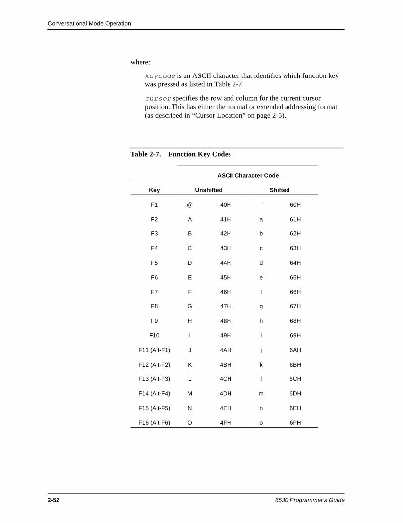
Conversational Mode Operation
2-52 6530 Programmer’s Guide
where:
keycode is an ASCII character that identifies which function key was pressed as listed in Table 2-7.
cursor specifies the row and column for the current cursor position. This has either the normal or extended addressing format (as described in “Cursor Location” on page 2-5).
Table 2-7. Function Key Codes
ASCII Character Code
Key Unshifted Shifted
F1 @ 40H ‘ 60H
F2 A 41H a 61H
F3 B 42H b 62H
F4 C 43H c 63H
F5 D 44H d 64H
F6 E 45H e 65H
F7 F 46H f 66H
F8 G 47H g 67H
F9 H 48H h 68H
F10 I 49H i 69H
F11 (Alt-F1) J 4AH j 6AH
F12 (Alt-F2) K 4BH k 6BH
F13 (Alt-F3) L 4CH l 6CH
F14 (Alt-F4) M 4DH m 6DH
F15 (Alt-F5) N 4EH n 6EH
F16 (Alt-F6) O 4FH o 6FH
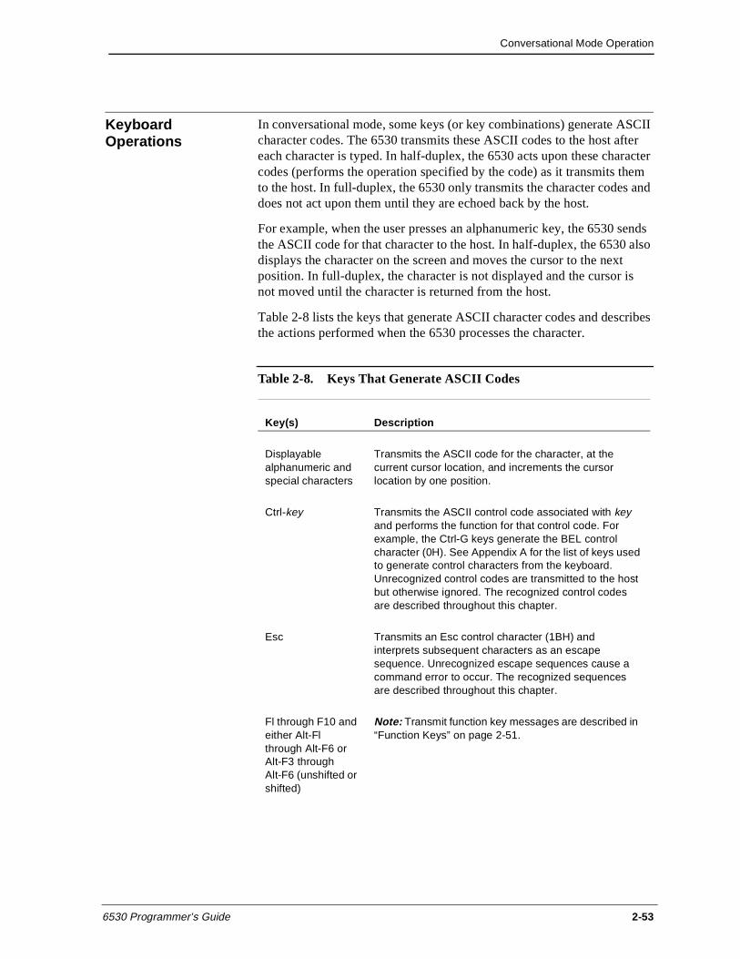
Conversational Mode Operation
6530 Programmer’s Guide 2-53
Keyboard Operations
In conversational mode, some keys (or key combinations) generate ASCII character codes. The 6530 transmits these ASCII codes to the host after each character is typed. In half-duplex, the 6530 acts upon these character codes (performs the operation specified by the code) as it transmits them to the host. In full-duplex, the 6530 only transmits the character codes and does not act upon them until they are echoed back by the host.
For example, when the user presses an alphanumeric key, the 6530 sends the ASCII code for that character to the host. In half-duplex, the 6530 also displays the character on the screen and moves the cursor to the next position. In full-duplex, the character is not displayed and the cursor is not moved until the character is returned from the host.
Table 2-8 lists the keys that generate ASCII character codes and describes the actions performed when the 6530 processes the character.
Table 2-8. Keys That Generate ASCII Codes
Key(s) Description
Displayable alphanumeric and special characters
Transmits the ASCII code for the character, at the current cursor location, and increments the cursor location by one position.
Ctrl-key Transmits the ASCII control code associated with key and performs the function for that control code. For example, the Ctrl-G keys generate the BEL control character (0H). See Appendix A for the list of keys used to generate control characters from the keyboard. Unrecognized control codes are transmitted to the host but otherwise ignored. The recognized control codes are described throughout this chapter.
Esc Transmits an Esc control character (1BH) and interprets subsequent characters as an escape sequence. Unrecognized escape sequences cause a command error to occur. The recognized sequences are described throughout this chapter.
Fl through F10 and either Alt-Fl through Alt-F6 or Alt-F3 through Alt-F6 (unshifted or shifted)
Note: Transmit function key messages are described in “Function Keys” on page 2-51.
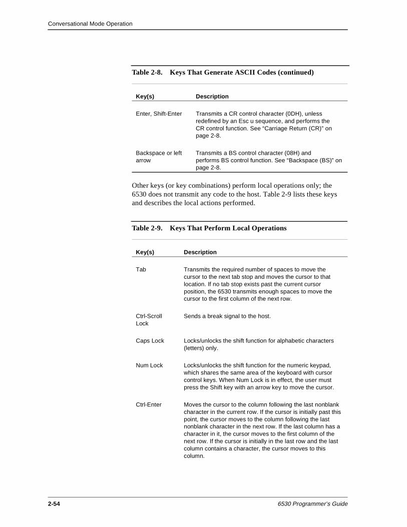
Conversational Mode Operation
2-54 6530 Programmer’s Guide
Other keys (or key combinations) perform local operations only; the 6530 does not transmit any code to the host. Table 2-9 lists these keys and describes the local actions performed.
Enter, Shift-Enter Transmits a CR control character (0DH), unless redefined by an Esc u sequence, and performs the CR control function. See “Carriage Return (CR)” on page 2-8.
Backspace or left arrow
Transmits a BS control character (08H) and performs BS control function. See “Backspace (BS)” on page 2-8.
Table 2-8. Keys That Generate ASCII Codes (continued)
Key(s) Description
Table 2-9. Keys That Perform Local Operations
Key(s) Description
Tab Transmits the required number of spaces to move the cursor to the next tab stop and moves the cursor to that location. If no tab stop exists past the current cursor position, the 6530 transmits enough spaces to move the cursor to the first column of the next row.
Ctrl-Scroll Lock
Sends a break signal to the host.
Caps Lock Locks/unlocks the shift function for alphabetic characters (letters) only.
Num Lock Locks/unlocks the shift function for the numeric keypad, which shares the same area of the keyboard with cursor control keys. When Num Lock is in effect, the user must press the Shift key with an arrow key to move the cursor.
Ctrl-Enter Moves the cursor to the column following the last nonblank character in the current row. If the cursor is initially past this point, the cursor moves to the column following the last nonblank character in the next row. If the last column has a character in it, the cursor moves to the first column of the next row. If the cursor is initially in the last row and the last column contains a character, the cursor moves to this column.
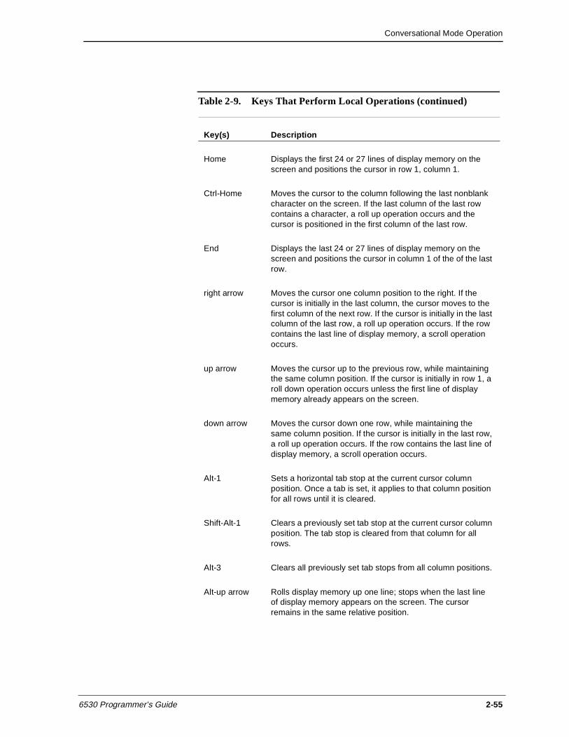
Conversational Mode Operation
6530 Programmer’s Guide 2-55
Home Displays the first 24 or 27 lines of display memory on the screen and positions the cursor in row 1, column 1.
Ctrl-Home Moves the cursor to the column following the last nonblank character on the screen. If the last column of the last row contains a character, a roll up operation occurs and the cursor is positioned in the first column of the last row.
End Displays the last 24 or 27 lines of display memory on the screen and positions the cursor in column 1 of the of the last row.
right arrow Moves the cursor one column position to the right. If the cursor is initially in the last column, the cursor moves to the first column of the next row. If the cursor is initially in the last column of the last row, a roll up operation occurs. If the row contains the last line of display memory, a scroll operation occurs.
up arrow Moves the cursor up to the previous row, while maintaining the same column position. If the cursor is initially in row 1, a roll down operation occurs unless the first line of display memory already appears on the screen.
down arrow Moves the cursor down one row, while maintaining the same column position. If the cursor is initially in the last row, a roll up operation occurs. If the row contains the last line of display memory, a scroll operation occurs.
Alt-1 Sets a horizontal tab stop at the current cursor column position. Once a tab is set, it applies to that column position for all rows until it is cleared.
Shift-Alt-1 Clears a previously set tab stop at the current cursor column position. The tab stop is cleared from that column for all rows.
Alt-3 Clears all previously set tab stops from all column positions.
Alt-up arrow Rolls display memory up one line; stops when the last line of display memory appears on the screen. The cursor remains in the same relative position.
Table 2-9. Keys That Perform Local Operations (continued)
Key(s) Description
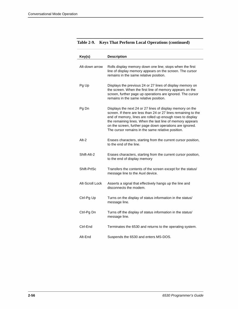
Conversational Mode Operation
2-56 6530 Programmer’s Guide
Alt-down arrow Rolls display memory down one line; stops when the first line of display memory appears on the screen. The cursor remains in the same relative position.
Pg Up Displays the previous 24 or 27 lines of display memory on the screen. When the first line of memory appears on the screen, further page up operations are ignored. The cursor remains in the same relative position.
Pg Dn Displays the next 24 or 27 lines of display memory on the screen. If there are less than 24 or 27 lines remaining to the end of memory, lines are rolled up enough rows to display the remaining lines. When the last line of memory appears on the screen, further page down operations are ignored. The cursor remains in the same relative position.
Alt-2 Erases characters, starting from the current cursor position, to the end of the line.
Shift-Alt-2 Erases characters, starting from the current cursor position, to the end of display memory
Shift-PrtSc Transfers the contents of the screen except for the status/message line to the Auxl device.
Alt-Scroll Lock Asserts a signal that effectively hangs up the line and disconnects the modem.
Ctrl-Pg Up Turns on the display of status information in the status/message line.
Ctrl-Pg Dn Turns off the display of status information in the status/message line.
Ctrl-End Terminates the 6530 and returns to the operating system.
Alt-End Suspends the 6530 and enters MS-DOS.
Table 2-9. Keys That Perform Local Operations (continued)
Key(s) Description
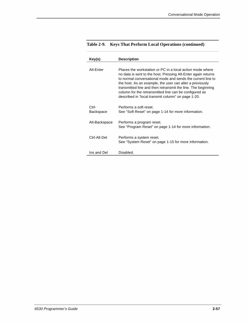
Conversational Mode Operation
6530 Programmer’s Guide 2-57
Alt-Enter Places the workstation or PC in a local action mode where no data is sent to the host. Pressing Alt-Enter again returns to normal conversational mode and sends the current line to the host. As an example, the user can alter a previously transmitted line and then retransmit the line. The beginning column for the retransmitted line can be configured as described in “local transmit column” on page 1-20.
Ctrl-Backspace
Performs a soft reset. See “Soft Reset” on page 1-14 for more information.
Alt-Backspace Performs a program reset. See “Program Reset” on page 1-14 for more information.
Ctrl-Alt-Del Performs a system reset. See “System Reset” on page 1-15 for more information.
Ins and Del Disabled.
Table 2-9. Keys That Perform Local Operations (continued)
Key(s) Description

Conversational Mode Operation
2-58 6530 Programmer’s Guide
6530 Programmer’s Guide 3-1
3Block Mode Operation
In block mode, the 6530 transmits data to and receives data from the host in blocks. The 6530 is always ready to receive blocks from the host; however, it only transmits a block when:
n The host application sends a control code or escape sequence that requests data from the 6530, (for example; Esc a (Read Cursor Address).
n The host application issues a read operation and the user presses a function key; in which case, the 6530 transmits a function key message to the host.
Block mode allows users to perform local editing operations (such as inserting or deleting characters) before the data is transmitted. In addition, protect submode allows your application to control the format of data on the screen and the type of characters that can be entered from the keyboard.
Display memory in block mode is organized into logical pages. Each page has its own cursor and buffer address. All keyboard operations take place on the currently displayed page at the cursor location. Your application program can select a page for I/O independently of the displayed page. Except for explicit cursor movement operations, your application program accesses memory on the selected page through the use of buffer addresses rather than cursor locations.
This section provides detailed descriptions of fields and field attributes (for protect submode), control codes and escape sequences, function keys and other keyboard operations available in block mode operation.
Fields and Field Attributes (Protect Submode)
In protect submode, your application can subdivide a page into fields. A field is defined as an area of positions on a page having the same data attributes. A field can be of any length from one cursor position up to the size of the page; thus, a field can span lines but it cannot cross page boundaries.
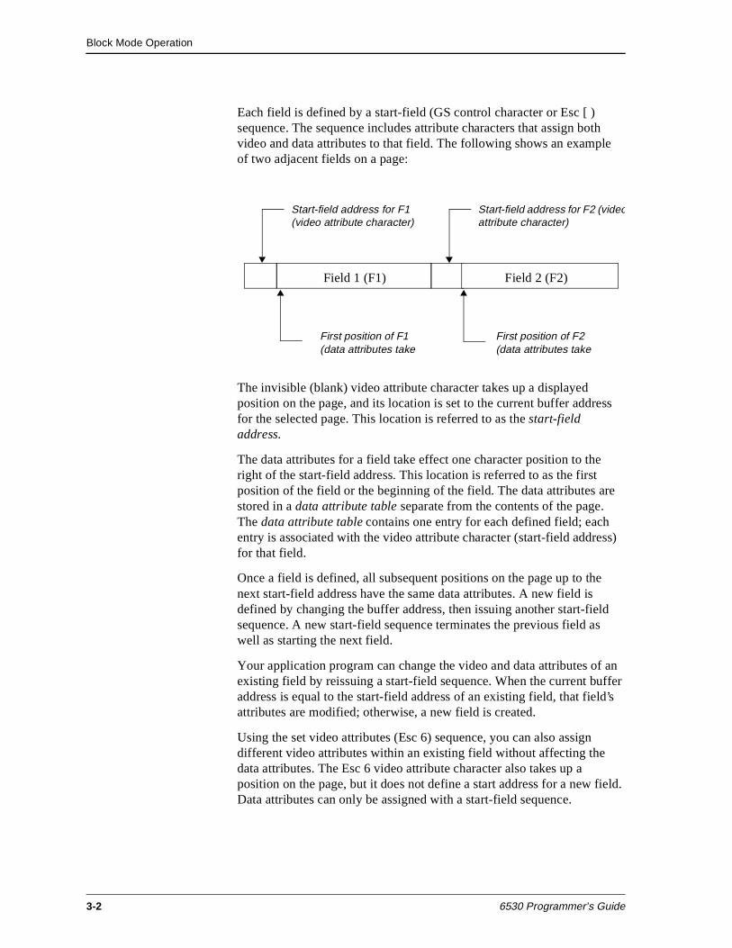
Block Mode Operation
3-2 6530 Programmer’s Guide
Each field is defined by a start-field (GS control character or Esc [ ) sequence. The sequence includes attribute characters that assign both video and data attributes to that field. The following shows an example of two adjacent fields on a page:
The invisible (blank) video attribute character takes up a displayed position on the page, and its location is set to the current buffer address for the selected page. This location is referred to as the start-field address.
The data attributes for a field take effect one character position to the right of the start-field address. This location is referred to as the first position of the field or the beginning of the field. The data attributes are stored in a data attribute table separate from the contents of the page. The data attribute table contains one entry for each defined field; each entry is associated with the video attribute character (start-field address) for that field.
Once a field is defined, all subsequent positions on the page up to the next start-field address have the same data attributes. A new field is defined by changing the buffer address, then issuing another start-field sequence. A new start-field sequence terminates the previous field as well as starting the next field.
Your application program can change the video and data attributes of an existing field by reissuing a start-field sequence. When the current buffer address is equal to the start-field address of an existing field, that field’s attributes are modified; otherwise, a new field is created.
Using the set video attributes (Esc 6) sequence, you can also assign different video attributes within an existing field without affecting the data attributes. The Esc 6 video attribute character also takes up a position on the page, but it does not define a start address for a new field. Data attributes can only be assigned with a start-field sequence.
Field 1 (F1) Field 2 (F2)
Start-field address for F1 (video attribute character)
First position of F1 (data attributes take
First position of F2 (data attributes take
Start-field address for F2 (videoattribute character)
Block Mode Operation
6530 Programmer’s Guide 3-3
The number of fields that can be defined depends on the size of the data attribute table. During block mode initialization, display memory is allocated a default maximum number of pages. The default varies with the 6530 and selected screen format. The rest of display memory is then allocated to the data attribute table for defining fields. The read terminal status (Esc ^) sequence returns the maximum number of pages available as well as the average number of fields that can be defined for each page. You can increase the amount of memory available for the data attribute table by decreasing the maximum number of pages allocated (with the Esc p sequence).
The data attribute character defines a field as either protected or unprotected. The protected attribute, when set, always takes precedence over the other data attributes for that field. Thus, when a field is defined as protected, any data attributes that would apply to unprotected fields are ignored. Unprotected fields can be modified from the keyboard as well as from the application. Protected fields cannot be modified from the keyboard, and the cursor cannot be positioned into these areas. However, your application program can write into both protected and unprotected fields.
Upon entering protect submode, all pages are cleared to blanks. Initially, each page is defined as having one field, whose start-field address isrow l, column 1. This is called the default field and is defined as a protected field. You can redefine the default field and/or define subsequent fields in any order. The start-field address (video attribute character) of each defined field is always protected, regardless of whether the field is protected or unprotected. Thus, there is always at least one protected blank between fields; and row l, column 1 is always a protected position.
In addition to the protected/unprotected attribute, you can assign other data attributes to a field, as described in the following paragraphs.
Modified Data Tags Each field, whether defined as unprotected or protected, has a modified data tag (MDT). During certain read operations (Esc = and Esc - J sequences), the 6530 transmits only those fields whose MDT is set; transmission of all other fields is suppressed.
The MDT for an unprotected field is set by the terminal whenever the user modifies the contents of that field, either by entering data or by performing an edit operation (such as Erase Line) that effects the field’s contents. Your application can reset the MDTs for all unprotected fields by issuing a reset modified data tags (Esc >) sequence.
Block Mode Operation
3-4 6530 Programmer’s Guide
Your application can also set the MDT for either an unprotected field or a protected field with the data attribute character for that field. This allows your application to always read a certain unprotected field or to read a certain protected field along with modified unprotected fields to ensure screen integrity. For example, you can define fixed data, such as a form identifier, as a protected field with the MDT bit set in the data attribute for that field. (To inhibit display on the screen, the field can be defined with an invisible video attribute.) When your application reads the page, the 6530 transmits the form identifier field as well as any unprotected fields that have been modified by the user.
Data Types The data type attribute defines what type of data may be entered from the keyboard into an unprotected field. For example, the data type attribute can be set to allow only numeric data to be entered into a particular field. No data type checking is done for data sent from your application.
As data is entered from the keyboard, the 6530 checks each character to determine whether it falls in the range of valid characters for the selected data type. If the character is valid, the 6530 writes the character into the field and continues processing. If the character is invalid, the character is not written into the field; instead, the 6530 sounds the audible alarm and displays an error message (INVALID DATA) in the error line. (The message is cleared on the next keystroke.)
The data type is set by three bits in the data attribute character. Eight different data types are available (0-7). The 6530 uses a predefined data type table, which specifies the displayable characters that are valid for each of the data types. If necessary, your application program can also redefine the data type table using the Esc r sequence.
Table 3-1 lists the predefined data types and summarizes the characters that are valid for each type. (Appendix D contains the complete table.) “X” indicates the characters that are valid for the data types listed in the first column.
Note A program or system reset, mode or submode switch, or reinitialization (Esc q) restores the predefined data type table.
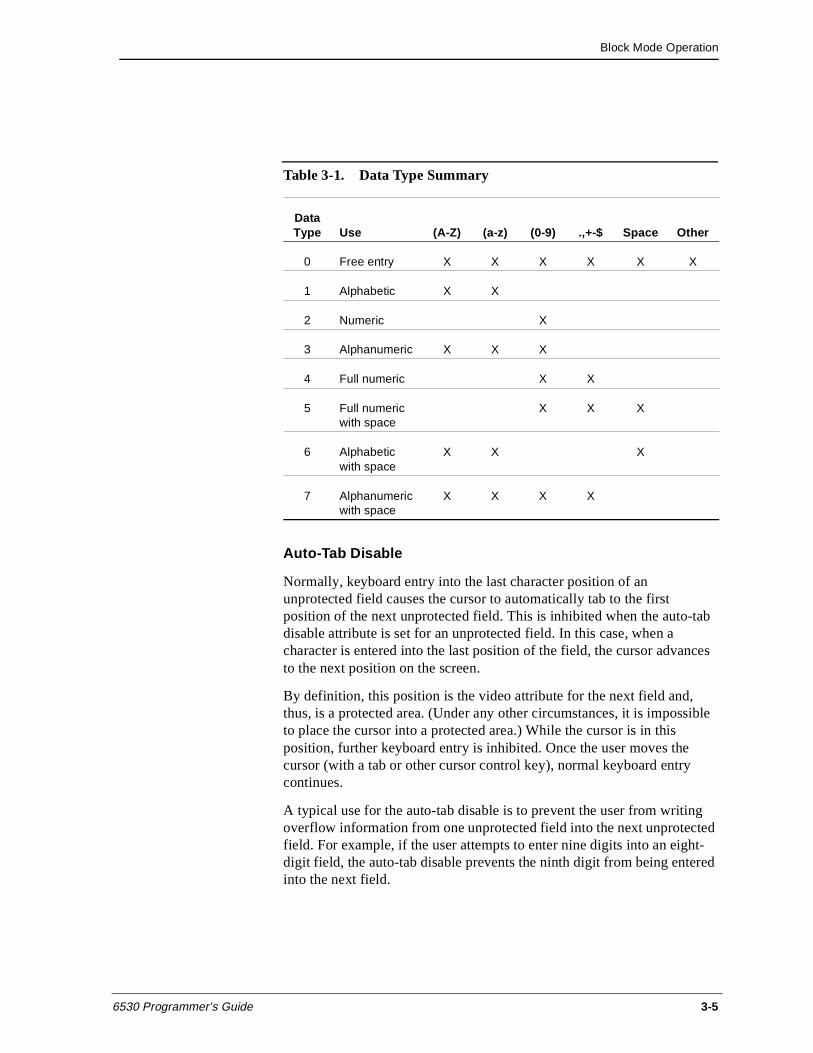
Block Mode Operation
6530 Programmer’s Guide 3-5
Auto-Tab Disable
Normally, keyboard entry into the last character position of an unprotected field causes the cursor to automatically tab to the first position of the next unprotected field. This is inhibited when the auto-tab disable attribute is set for an unprotected field. In this case, when a character is entered into the last position of the field, the cursor advances to the next position on the screen.
By definition, this position is the video attribute for the next field and, thus, is a protected area. (Under any other circumstances, it is impossible to place the cursor into a protected area.) While the cursor is in this position, further keyboard entry is inhibited. Once the user moves the cursor (with a tab or other cursor control key), normal keyboard entry continues.
A typical use for the auto-tab disable is to prevent the user from writing overflow information from one unprotected field into the next unprotected field. For example, if the user attempts to enter nine digits into an eight-digit field, the auto-tab disable prevents the ninth digit from being entered into the next field.
Table 3-1. Data Type Summary
DataType Use (A-Z) (a-z) (0-9) .,+-$ Space Other
0 Free entry X X X X X X
1 Alphabetic X X
2 Numeric X
3 Alphanumeric X X X
4 Full numeric X X
5 Full numeric with space
X X X
6 Alphabetic with space
X X X
7 Alphanumeric with space
X X X X
Block Mode Operation
3-6 6530 Programmer’s Guide
Upshift
The upshift attribute, when set, causes the 6530 to convert all alphabetic characters (letters a-z) entered from the keyboard to uppercase letters before writing them into that field. This attribute affects only alphabetic characters entered from the keyboard; it has no effect on characters sent by your application. You must use the start field extended (Esc [) sequence to set this attribute.
Alternate Input Device
By default, fields are defined to accept local input from the keyboard only. Your application can define a field to accept input from an alternate input device (AID). You must use the start field extended (Esc [) sequence to set this attribute.
Control Codes and Escape Sequences
Your application program can control 6530 operation by sending control codes and escape sequences. A control code is represented by an ASCII character in the range of 00 to 1FH. These control codes are not displayed or stored in memory; instead, they invoke communications or terminal control functions. The 6530 recognizes a subset of codes in the control character range. See “Character Codes” on page 1-8 for details.
Escape sequences comprise a header, followed by a unique instruction code, which may be followed by a required or optional parameter. Your application program issues an escape sequence by sending the ASCII code which represents the Esc character (1BH) followed by the ASCII characters that represent the unique instruction code, followed by any required or optional parameters. When the 6530 recognizes an escape code, it performs the control function associated with that unique code. When the 6530 receives an unrecognized escape code, it issues a command error and aborts the sequence.
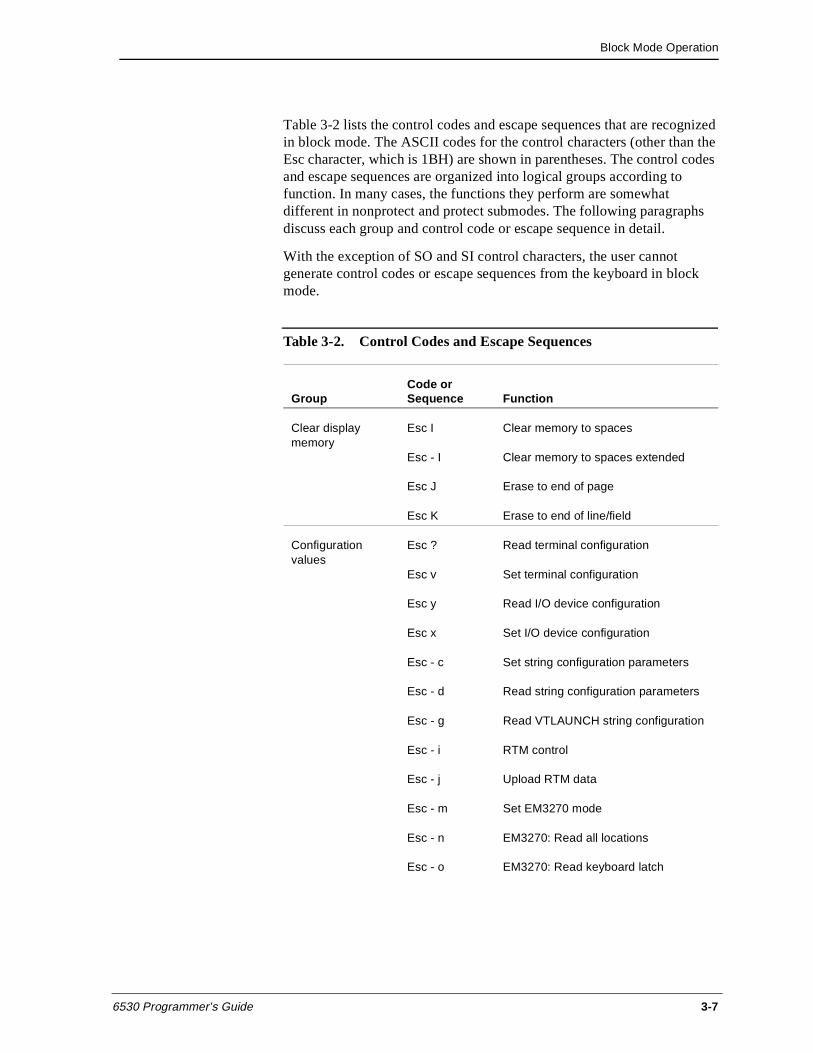
Block Mode Operation
6530 Programmer’s Guide 3-7
Table 3-2 lists the control codes and escape sequences that are recognized in block mode. The ASCII codes for the control characters (other than the Esc character, which is 1BH) are shown in parentheses. The control codes and escape sequences are organized into logical groups according to function. In many cases, the functions they perform are somewhat different in nonprotect and protect submodes. The following paragraphs discuss each group and control code or escape sequence in detail.
With the exception of SO and SI control characters, the user cannot generate control codes or escape sequences from the keyboard in block mode.
Table 3-2. Control Codes and Escape Sequences
GroupCode or Sequence Function
Clear display memory
Esc I Clear memory to spaces
Esc - I Clear memory to spaces extended
Esc J Erase to end of page
Esc K Erase to end of line/field
Configuration values
Esc ? Read terminal configuration
Esc v Set terminal configuration
Esc y Read I/O device configuration
Esc x Set I/O device configuration
Esc - c Set string configuration parameters
Esc - d Read string configuration parameters
Esc - g Read VTLAUNCH string configuration
Esc - i RTM control
Esc - j Upload RTM data
Esc - m Set EM3270 mode
Esc - n EM3270: Read all locations
Esc - o EM3270: Read keyboard latch
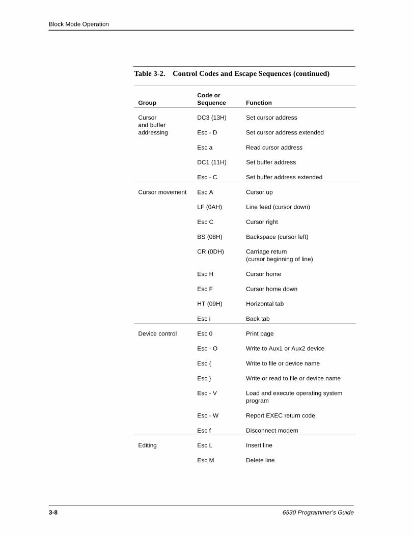
Block Mode Operation
3-8 6530 Programmer’s Guide
Cursor and buffer addressing
DC3 (13H) Set cursor address
Esc - D Set cursor address extended
Esc a Read cursor address
DC1 (11H) Set buffer address
Esc - C Set buffer address extended
Cursor movement Esc A Cursor up
LF (0AH) Line feed (cursor down)
Esc C Cursor right
BS (08H) Backspace (cursor left)
CR (0DH) Carriage return (cursor beginning of line)
Esc H Cursor home
Esc F Cursor home down
HT (09H) Horizontal tab
Esc i Back tab
Device control Esc 0 Print page
Esc - O Write to Aux1 or Aux2 device
Esc { Write to file or device name
Esc } Write or read to file or device name
Esc - V Load and execute operating system program
Esc - W Report EXEC return code
Esc f Disconnect modem
Editing Esc L Insert line
Esc M Delete line
Table 3-2. Control Codes and Escape Sequences (continued)
GroupCode or Sequence Function
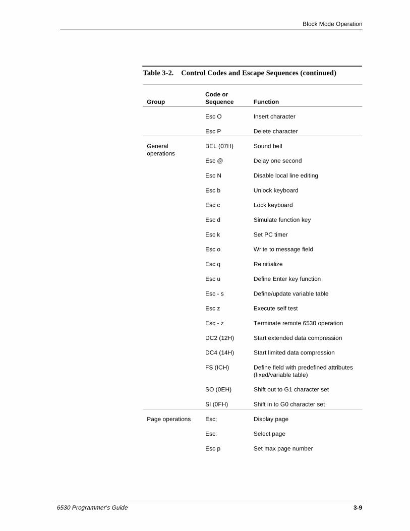
Block Mode Operation
6530 Programmer’s Guide 3-9
Esc O Insert character
Esc P Delete character
General operations
BEL (07H) Sound bell
Esc @ Delay one second
Esc N Disable local line editing
Esc b Unlock keyboard
Esc c Lock keyboard
Esc d Simulate function key
Esc k Set PC timer
Esc o Write to message field
Esc q Reinitialize
Esc u Define Enter key function
Esc - s Define/update variable table
Esc z Execute self test
Esc - z Terminate remote 6530 operation
DC2 (12H) Start extended data compression
DC4 (14H) Start limited data compression
FS (ICH) Define field with predefined attributes (fixed/variable table)
SO (0EH) Shift out to G1 character set
SI (0FH) Shift in to G0 character set
Page operations Esc; Display page
Esc: Select page
Esc p Set max page number
Table 3-2. Control Codes and Escape Sequences (continued)
GroupCode or Sequence Function
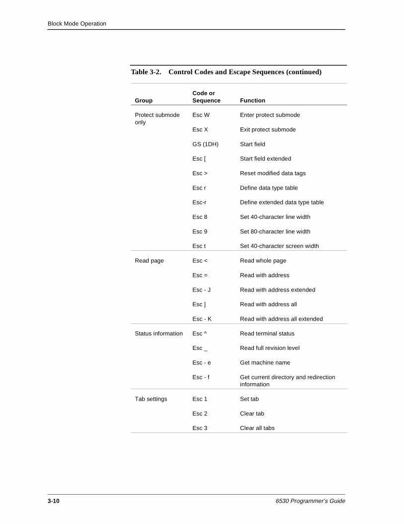
Block Mode Operation
3-10 6530 Programmer’s Guide
Protect submodeonly
Esc W Enter protect submode
Esc X Exit protect submode
GS (1DH) Start field
Esc [ Start field extended
Esc > Reset modified data tags
Esc r Define data type table
Esc-r Define extended data type table
Esc 8 Set 40-character line width
Esc 9 Set 80-character line width
Esc t Set 40-character screen width
Read page Esc < Read whole page
Esc = Read with address
Esc - J Read with address extended
Esc ] Read with address all
Esc - K Read with address all extended
Status information Esc ^ Read terminal status
Esc _ Read full revision level
Esc - e Get machine name
Esc - f Get current directory and redirection information
Tab settings Esc 1 Set tab
Esc 2 Clear tab
Esc 3 Clear all tabs
Table 3-2. Control Codes and Escape Sequences (continued)
GroupCode or Sequence Function
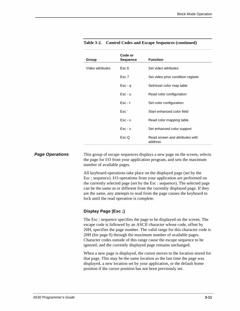
Block Mode Operation
6530 Programmer’s Guide 3-11
Page Operations This group of escape sequences displays a new page on the screen, selects the page for I/O from your application program, and sets the maximum number of available pages.
All keyboard operations take place on the displayed page (set by the Esc ; sequence). I/O operations from your application are performed on the currently selected page (set by the Esc : sequence). The selected page can be the same as or different from the currently displayed page. If they are the same, any attempts to read from the page causes the keyboard to lock until the read operation is complete.
Display Page (Esc ;)
The Esc ; sequence specifies the page to be displayed on the screen. The escape code is followed by an ASCII character whose code, offset by 20H, specifies the page number. The valid range for this character code is 20H (for page 0) through the maximum number of available pages. Character codes outside of this range cause the escape sequence to be ignored, and the currently displayed page remains unchanged.
When a new page is displayed, the cursor moves to the location stored for that page. This may be the same location as the last time the page was displayed, a new location set by your application, or the default home position if the cursor position has not been previously set.
Video attributes Esc 6 Set video attributes
Esc 7 Set video prior condition register
Esc - q Set/reset color map table
Esc - u Read color configuration
Esc - t Set color configuration
Esc ’ Start enhanced color field
Esc - v Read color mapping table
Esc - x Set enhanced color support
Esc Q Read screen and attributes with address
Table 3-2. Control Codes and Escape Sequences (continued)
GroupCode or Sequence Function
Block Mode Operation
3-12 6530 Programmer’s Guide
Once set, the display page continues to be displayed until another Esc ; sequence is issued. The default page used immediately after entering block mode is page 1.
Displaying page 0 (20H) locks the keyboard and displays a blank screen. This is useful for preventing video flash, which occurs if your application simultaneously displays and writes video attributes to the same page. For example, your application can display page 0 while it is writing to page 1.
Select Page (Esc :)
The Esc : sequence selects the memory page accessed by your application program. The escape code is followed by an ASCII character whose code, offset by 20H, specifies the page number. The valid range for this character code is 21H (for page l) through the maximum number of available pages. Character codes outside of this range cause the escape sequence to be ignored, and the currently selected page remains unchanged.
Once a page is selected, it remains selected until another Esc : sequence is issued. The default page number used immediately after entering block mode is page 1.
Set Max Page Number (Esc p)
The Esc p sequence changes the default value for the maximum number of pages allocated. Typically, this escape sequence is used to increase the amount of memory available for defining fields in protect submode. The Esc p is followed by an ASCII character whose code, offset by 30H, specifies the maximum number of pages to be allocated. For example, the character 7 causes the 6530 to allocate memory for up to 7 pages.
The default values and the absolute maximum number of available pages depends on the screen format selected. You can use the Esc ^ (read terminal status) sequence to determine the number of pages available. Specifying a value greater than the absolute results in a default to the absolute maximum.
The new value set for the maximum page number does not take effect until a switch to a submode occurs or the screen format is changed.
Block Mode Operation
6530 Programmer’s Guide 3-13
Cursor and Buffer Addressing
This group of control codes and escape sequences sets new locations for the cursor and buffer addresses on the selected page. Each page has its own cursor address and buffer address, which can be the same or different for each page. You can change the cursor or buffer address on one page without affecting the addresses on other pages.
Your application accesses memory on the selected page through either the cursor address or the buffer address for that page. Operations that involve explicit cursor movement, such as a backspace or line feed, use the current cursor address for the selected page. Other operations, such as reads and writes to the selected page, use the current buffer address for that page.
Both the cursor and buffer addresses are specified by row and column positions. The home location (upper, left corner) is row l, column 1. The address can take one of two forms, called normal and extended addressing.
In normal addressing, the row and column positions are specified by encoded ASCII characters whose codes, offset by IFH, represent the positions. For example, the home cursor location (row 1, column 1) is specified by two ASCII space characters (20H). The next location (row 1, column 2) is specified by a space character (20H) and a ! character (21H).
Valid row positions are encoded in the range of 20H through 37H; valid column positions are encoded in the range of 20H through 6FH. A character outside of this range causes a command error to occur.
In extended addressing, the row and column positions are specified by decimal numbers represented as a string of ASCII characters. The row and column numbers are separated by a semicolon (;). Row position values greater than 24 and column values greater than 80 are interpreted, but default to 24 and 80, respectively
In protect submode, the cursor cannot be positioned into a protected field from either the keyboard or your application program. However, the buffer address can access any area of the page. Thus, your application can write to or read from any field.
Block Mode Operation
3-14 6530 Programmer’s Guide
Set Cursor Address (DC3)
The DC3 control character (l3H) sets a new cursor position for the selected page using normal addressing as described above. Typically, this cursor address is used as the reference address for subsequent keyboard input. You can use this control sequence to access any screen position up to 96 columns. The DC3 character must be followed by two encoded ASCII characters that specify the new row and column positions for the cursor. The following sequence sets the new cursor location to row 5, column 2:
13H $ !
In protect submode, if the new cursor address is a protected position, the cursor moves to the first position of the next unprotected field.
Note For information about cursor movement in EM3270 mode, see “Cursor Positioning” on page 3-68.
Set Cursor Address Extended (Esc - D)
The Esc - D sequence sets a new cursor position for the selected page with extended addressing format (as described in “Cursor and Buffer Addressing” on page 3-13). You can use this escape sequence to access all positions for any screen format selected. The format for the escape sequence is as follows:
Esc - row ; column D
where;
row and column are decimal numbers that specify the new cursor location.
D terminates the sequence.
For example, the following sequence sets the new cursor location to row 5, column 72:
1BH - 5;72 D
In protect submode, if the new cursor address is a protected position, the cursor moves to the first position in the next unprotected field.
Block Mode Operation
6530 Programmer’s Guide 3-15
Read Cursor Address (Esc a)
The Esc a escape sequence causes the 6530 to transmit the cursor address for the currently selected page. The message returned to the host uses normal addressing and has the following general format:
SOH _ page row column terminator
where:
SOH is start of header (01H).
The underscore (_) identifies this message as a cursor address message.
page is an ASCII character whose code offset by 20H specifies the page number of the currently selected page.
row and column are encoded ASCII characters that specify the current cursor position.
terminator comprises the control characters ETX (03H) and LRC (Longitudinal Redundancy Check) in block mode.
In protect submode, the cursor will not be displayed on the screen if there are no unprotected fields in the page. In this case, the cursor position indicates that the cursor is in line l, column 1 of the page. because it is impossible for this position to be unprotected, this address can be used to detect the condition.
Note In EM3270 mode, the cursor is always displayed, regardless of the presence of unprotected fields.
Set Buffer Address (DC1)
The DC1 control character (11H) sets the buffer address for the selected page, using normal addressing (as described in “Cursor and Buffer Addressing” on page 3-13). This buffer address acts as the starting address for the next I/O operation directed to the page, such as a read or write operation. You can use this control sequence to access any position up to 80 columns. The DCl character must be followed by two encoded ASCII characters that specify new row and column positions for the buffer address. For example, the following sets the buffer address to row 5, column 2:
11H $ !
Block Mode Operation
3-16 6530 Programmer’s Guide
Set Buffer Address Extended (Esc - C)
The Esc - C sequence sets a new buffer address for the selected page with normal addressing as described in “Cursor and Buffer Addressing” on page 3-13. You can use this escape sequence to access all positions for any screen format selected. The format for the escape sequence is as follows:
Esc - row ; column C
where:
row and column are decimal numbers that specify the new buffer address.
C terminates the sequence.
For example, the following sequence sets the new buffer address to row 5, column 72:
1BH - 5;72 C
Cursor Movement This group of control codes and escape sequences provides explicit control of cursor movement on the selected page. These operations are relative to the current cursor address.
In nonprotect submode, the cursor can be positioned anywhere on the page, but it cannot be moved off the page. Attempts to move the cursor off the right side of the page result in the cursor wrapping to the first column of the next row. Attempts to move the cursor off the left side of the page result in the cursor wrapping to the last column of the previous row. Attempts to move the cursor off the top or bottom of the page result in the cursor wrapping to the opposite edge of the page. Tabbing is handled through column tab stops, which can be set by escape sequences (as described in “Tab Settings” on page 3-19).
Note In protect submode, tab stops are disabled and tabbing is handled on a field-by-field basis. A forward tab moves the cursor to the first position of the next unprotected field (searching right and then down). A back tab moves the cursor to the first position of the current or previous unprotected field (searching left and then up).
When the cursor is positioned into a protected field, the 6530 automatically performs either a forward or back tab operation to move the cursor from the protected position to an unprotected position. For example:
Block Mode Operation
6530 Programmer’s Guide 3-17
n If the cursor is moved right or down into a protected field, the 6530 forward tabs, placing the cursor in the first position of the next unprotected field.
n If the cursor is moved up into a protected field, the 6530 back tabs, placing the cursor in the first position of the previous unprotected field.
n If the cursor is moved left into a protected field, the 6530 first back tabs the cursor to the previous unprotected field and then moves it to the last column of that field.
The search for an unprotected field wraps around the page if necessary. If no unprotected fields exist on the page, the cursor is not displayed.
Cursor Up (Esc A)
The Esc A sequence moves the cursor up to the previous row, while maintaining the same column position. If the cursor is initially in row 1, the cursor wraps to the last row of the page.
In protect submode, if the new cursor position is protected, a back tab operation occurs.
Line Feed (LF)
The LF control character (0AH) moves the cursor down one row, while maintaining the same column position. If the cursor is initially in the last row, the cursor wraps to the top row of the page.
In protect submode, if the new cursor position is protected, a forward tab operation occurs.
Cursor Right (Esc C)
The Esc C sequence moves the cursor one column position to the right. If the cursor is initially in the last column, the cursor moves to the first column of the next row. If the cursor is initially in the last column of the last row, the cursor wraps to the first column of the first row.
In protect submode, if the new cursor position is protected, a forward tab operation occurs.
Block Mode Operation
3-18 6530 Programmer’s Guide
Backspace (BS)
The BS control character (08H) moves the cursor one column position to the left. If the cursor is initially in column l, the cursor moves to the last column of the previous row. If the cursor is initially in row 1, column l, the cursor wraps to the last column of the last row. The backspace is nondestructive.
In protect submode, if the new cursor position is protected, the 6530 first back tabs to the previous unprotected field and then moves the cursor to the last column of that field.
Carriage Return (CR)
The CR control character (0DH) moves the cursor to column 1 of the current row.
In protect submode, if the new cursor position is protected, a forward tab operation occurs.
Cursor Home (Esc H)
The Esc H sequence moves the cursor to the first column of the first row (nonprotect submode) or the first position of the first unprotected field (protect submode).
Cursor Home Down (Esc F)
The Esc F sequence moves the cursor to the first column of the last row (nonprotect submode) or the first position of the last unprotected field (protect submode).
Horizontal Tab (HT)
The HT control character (09H) moves the cursor forward (right) to the next horizontal tab stop in nonprotect submode. See page 3-16 for details on setting tabs. If the cursor is initially positioned past the row’s last tab stop, the cursor moves to column 1 of the next row.
In protect submode, the cursor moves to the first position of the next unprotected field (searching right and then down). If no unprotected fields are encountered before the end of the page, the cursor wraps around to the home position and the search continues.
Block Mode Operation
6530 Programmer’s Guide 3-19
Back Tab (Esc i)
The Esc i sequence moves the cursor to the previous tab stop in nonprotect submode. If no previous tab stops exist on the current row, the cursor moves to the first column of the row. If the cursor is initially in column l, a back tab moves the cursor to the right-most tab stop of the previous row. If the cursor is initially in row 1, column l, the cursor moves to the right-most tab stop of the last row.
In protect submode, a back tab moves the cursor to the first position of the current unprotected field. If the cursor is initially in the first position of a field, the cursor moves to the first position of the previous unprotected field.
Tab Settings This group of escape sequences sets or clears tab stops. The 6530 maintains only one set of tab stops, which applies to all pages. These escape sequences are valid only in nonprotect submode; they are ignored in protect submode.
Set Tab (Esc 1)
The Esc 1 sequence sets a horizontal tab stop at the column position of the current buffer address. Once a tab is set, it applies to that column position for all rows on every page until it is cleared. The tab stop does not take up a position on the screen.
Clear Tab (Esc 2)
The Esc 2 sequence clears a previously set tab stop at the column position of the current buffer address. This tab stop is cleared from that column for all rows on every page.
Clear All Tabs (Esc 3)
The Esc 3 sequence clears all previously set tab stops from all column positions on every page.
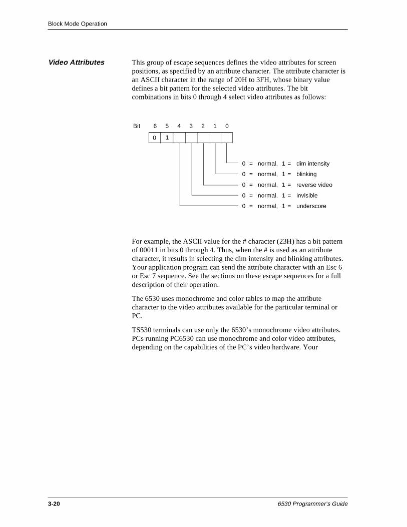
Block Mode Operation
3-20 6530 Programmer’s Guide
Video Attributes This group of escape sequences defines the video attributes for screen positions, as specified by an attribute character. The attribute character is an ASCII character in the range of 20H to 3FH, whose binary value defines a bit pattern for the selected video attributes. The bit combinations in bits 0 through 4 select video attributes as follows:
For example, the ASCII value for the # character (23H) has a bit pattern of 00011 in bits 0 through 4. Thus, when the # is used as an attribute character, it results in selecting the dim intensity and blinking attributes. Your application program can send the attribute character with an Esc 6 or Esc 7 sequence. See the sections on these escape sequences for a full description of their operation.
The 6530 uses monochrome and color tables to map the attribute character to the video attributes available for the particular terminal or PC.
TS530 terminals can use only the 6530’s monochrome video attributes. PCs running PC6530 can use monochrome and color video attributes, depending on the capabilities of the PC’s video hardware. Your
Bit 6 5 4 3 2 1 0
0 = normal, 1 = dim intensity
0 = normal, 1 = blinking
0 = normal, 1 = reverse video
0 = normal, 1 = invisible
0 = normal, 1 = underscore
0 1
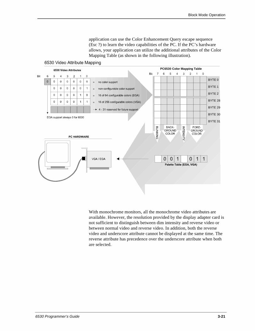
Block Mode Operation
6530 Programmer’s Guide 3-21
application can use the Color Enhancement Query escape sequence(Esc ?) to learn the video capabilities of the PC. If the PC’s hardware allows, your application can utilize the additional attributes of the Color Mapping Table (as shown in the following illustration).
With monochrome monitors, all the monochrome video attributes are available. However, the resolution provided by the display adapter card is not sufficient to distinguish between dim intensity and reverse video or between normal video and reverse video. In addition, both the reverse video and underscore attribute cannot be displayed at the same time. The reverse attribute has precedence over the underscore attribute when both are selected.
BYTE 0
BYTE 1
BYTE 2
BYTE 28
BYTE 29
BYTE 30
BYTE 31
PC6530 Color Mapping Table
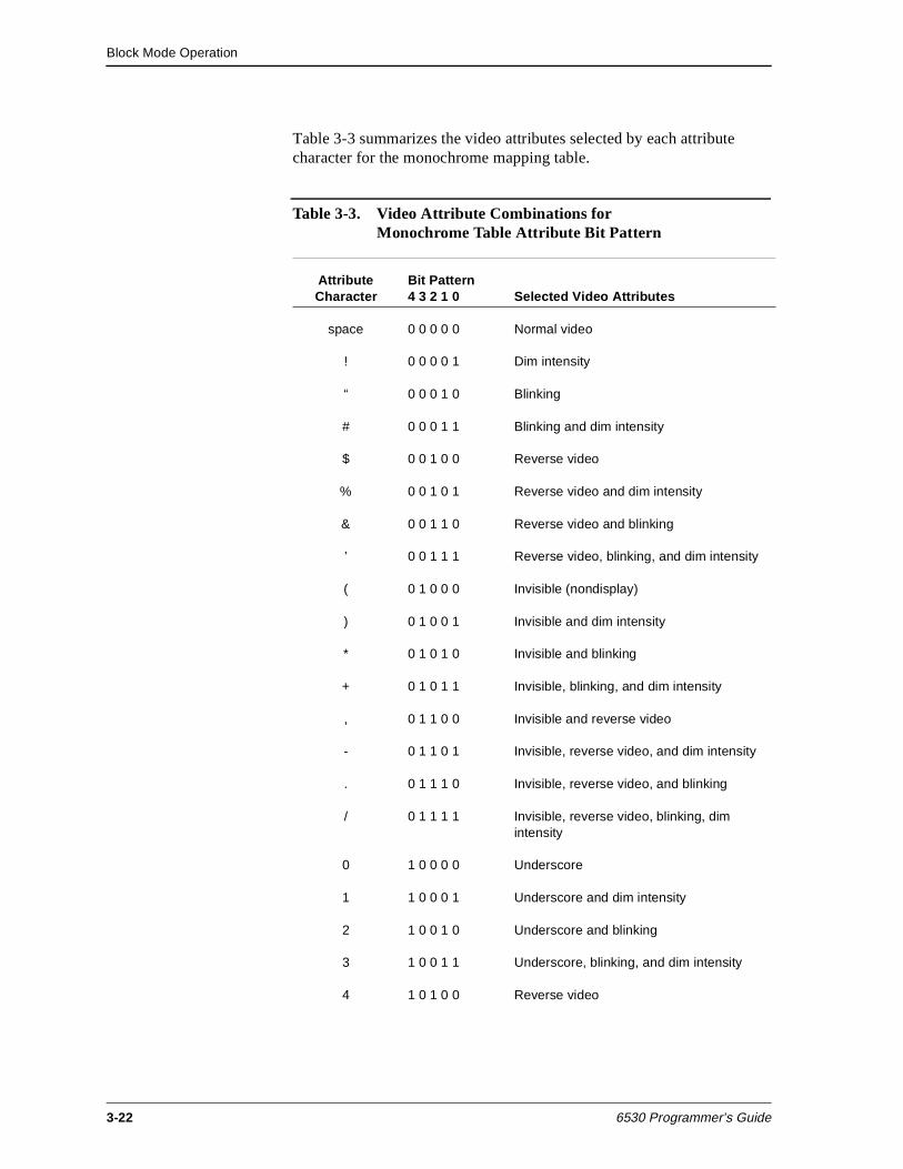
Block Mode Operation
3-22 6530 Programmer’s Guide
Table 3-3 summarizes the video attributes selected by each attribute character for the monochrome mapping table.
Table 3-3. Video Attribute Combinations for Monochrome Table Attribute Bit Pattern
Attribute Character
Bit Pattern 4 3 2 1 0 Selected Video Attributes
space 0 0 0 0 0 Normal video
! 0 0 0 0 1 Dim intensity
“ 0 0 0 1 0 Blinking
# 0 0 0 1 1 Blinking and dim intensity
$ 0 0 1 0 0 Reverse video
% 0 0 1 0 1 Reverse video and dim intensity
& 0 0 1 1 0 Reverse video and blinking
’ 0 0 1 1 1 Reverse video, blinking, and dim intensity
( 0 1 0 0 0 Invisible (nondisplay)
) 0 1 0 0 1 Invisible and dim intensity
* 0 1 0 1 0 Invisible and blinking
+ 0 1 0 1 1 Invisible, blinking, and dim intensity
, 0 1 1 0 0 Invisible and reverse video
- 0 1 1 0 1 Invisible, reverse video, and dim intensity
. 0 1 1 1 0 Invisible, reverse video, and blinking
/ 0 1 1 1 1 Invisible, reverse video, blinking, dim intensity
0 1 0 0 0 0 Underscore
1 1 0 0 0 1 Underscore and dim intensity
2 1 0 0 1 0 Underscore and blinking
3 1 0 0 1 1 Underscore, blinking, and dim intensity
4 1 0 1 0 0 Reverse video
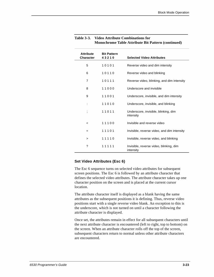
Block Mode Operation
6530 Programmer’s Guide 3-23
Set Video Attributes (Esc 6)
The Esc 6 sequence turns on selected video attributes for subsequent screen positions. The Esc 6 is followed by an attribute character that defines the selected video attributes. The attribute character takes up one character position on the screen and is placed at the current cursor location.
The attribute character itself is displayed as a blank having the same attributes as the subsequent positions it is defining. Thus, reverse video positions start with a single reverse video blank. An exception to this is the underscore, which is not turned on until a character following the attribute character is displayed.
Once set, the attributes remain in effect for all subsequent characters until the next attribute character is encountered (left to right, top to bottom) on the screen. When an attribute character rolls off the top of the screen, subsequent characters return to normal unless other attribute characters are encountered.
5 1 0 1 0 1 Reverse video and dim intensity
6 1 0 1 1 0 Reverse video and blinking
7 1 0 1 1 1 Reverse video, blinking, and dim intensity
8 1 1 0 0 0 Underscore and invisible
9 1 1 0 0 1 Underscore, invisible, and dim intensity
: 1 1 0 1 0 Underscore, invisible, and blinking
; 1 1 0 1 1 Underscore, invisible, blinking, dim intensity
< 1 1 1 0 0 Invisible and reverse video
= 1 1 1 0 1 Invisible, reverse video, and dim intensity
> 1 1 1 1 0 Invisible, reverse video, and blinking
? 1 1 1 1 1 Invisible, reverse video, blinking, dim intensity
Table 3-3. Video Attribute Combinations for Monochrome Table Attribute Bit Pattern (continued)
Attribute Character
Bit Pattern 4 3 2 1 0 Selected Video Attributes
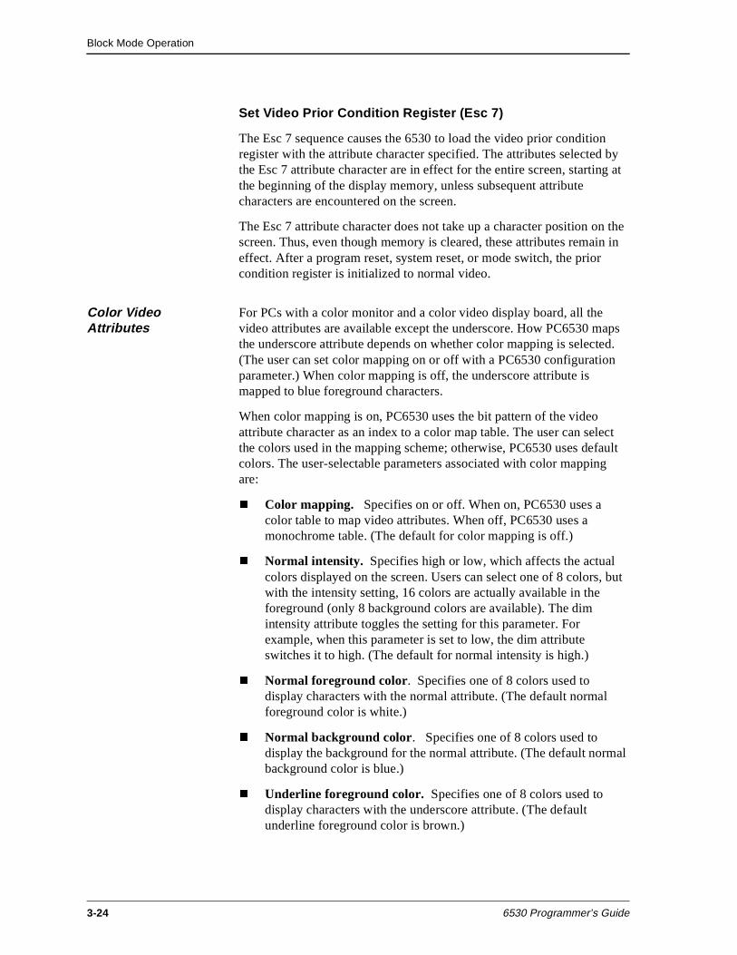
Block Mode Operation
3-24 6530 Programmer’s Guide
Set Video Prior Condition Register (Esc 7)
The Esc 7 sequence causes the 6530 to load the video prior condition register with the attribute character specified. The attributes selected by the Esc 7 attribute character are in effect for the entire screen, starting at the beginning of the display memory, unless subsequent attribute characters are encountered on the screen.
The Esc 7 attribute character does not take up a character position on the screen. Thus, even though memory is cleared, these attributes remain in effect. After a program reset, system reset, or mode switch, the prior condition register is initialized to normal video.
Color Video Attributes
For PCs with a color monitor and a color video display board, all the video attributes are available except the underscore. How PC6530 maps the underscore attribute depends on whether color mapping is selected. (The user can set color mapping on or off with a PC6530 configuration parameter.) When color mapping is off, the underscore attribute is mapped to blue foreground characters.
When color mapping is on, PC6530 uses the bit pattern of the video attribute character as an index to a color map table. The user can select the colors used in the mapping scheme; otherwise, PC6530 uses default colors. The user-selectable parameters associated with color mapping are:
n Color mapping. Specifies on or off. When on, PC6530 uses a color table to map video attributes. When off, PC6530 uses a monochrome table. (The default for color mapping is off.)
n Normal intensity. Specifies high or low, which affects the actual colors displayed on the screen. Users can select one of 8 colors, but with the intensity setting, 16 colors are actually available in the foreground (only 8 background colors are available). The dim intensity attribute toggles the setting for this parameter. For example, when this parameter is set to low, the dim attribute switches it to high. (The default for normal intensity is high.)
n Normal foreground color. Specifies one of 8 colors used to display characters with the normal attribute. (The default normal foreground color is white.)
n Normal background color. Specifies one of 8 colors used to display the background for the normal attribute. (The default normal background color is blue.)
n Underline foreground color. Specifies one of 8 colors used to display characters with the underscore attribute. (The default underline foreground color is brown.)
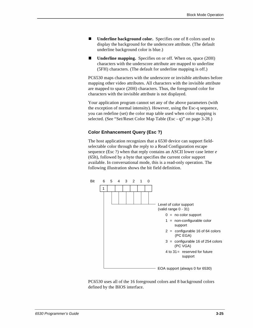
Block Mode Operation
6530 Programmer’s Guide 3-25
n Underline background color. Specifies one of 8 colors used to display the background for the underscore attribute. (The default underline background color is blue.)
n Underline mapping. Specifies on or off. When on, space (20H) characters with the underscore attribute are mapped to underline (5FH) characters. (The default for underline mapping is off.)
PC6530 maps characters with the underscore or invisible attributes before mapping other video attributes. All characters with the invisible attribute are mapped to space (20H) characters. Thus, the foreground color for characters with the invisible attribute is not displayed.
Your application program cannot set any of the above parameters (with the exception of normal intensity). However, using the Esc-q sequence, you can redefine (set) the color map table used when color mapping is selected. (See “Set/Reset Color Map Table (Esc - q)” on page 3-28.)
Color Enhancement Query (Esc ?)
The host application recognizes that a 6530 device can support field-selectable color through the reply to a Read Configuration escape sequence (Esc ?) when that reply contains an ASCII lower case letter e (65h), followed by a byte that specifies the current color support available. In conversational mode, this is a read-only operation. The following illustration shows the bit field definition.
PC6530 uses all of the 16 foreground colors and 8 background colors defined by the BIOS interface.
Bit 6 5 4 3 2 1 0
Level of color support (valid range 0 - 31)
0 = no color support
1 = non-configurable color support
2 = configurable 16 of 64 colors(PC EGA)
3 = configurable 16 of 254 colors(PC VGA)
4 to 31= reserved for futuresupport
1
EOA support (always 0 for 6530)
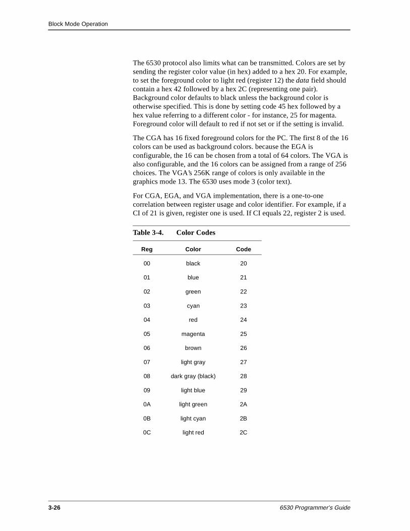
Block Mode Operation
3-26 6530 Programmer’s Guide
The 6530 protocol also limits what can be transmitted. Colors are set by sending the register color value (in hex) added to a hex 20. For example, to set the foreground color to light red (register 12) the data field should contain a hex 42 followed by a hex 2C (representing one pair). Background color defaults to black unless the background color is otherwise specified. This is done by setting code 45 hex followed by a hex value referring to a different color - for instance, 25 for magenta. Foreground color will default to red if not set or if the setting is invalid.
The CGA has 16 fixed foreground colors for the PC. The first 8 of the 16 colors can be used as background colors. because the EGA is configurable, the 16 can be chosen from a total of 64 colors. The VGA is also configurable, and the 16 colors can be assigned from a range of 256 choices. The VGA’s 256K range of colors is only available in the graphics mode 13. The 6530 uses mode 3 (color text).
For CGA, EGA, and VGA implementation, there is a one-to-one correlation between register usage and color identifier. For example, if a CI of 21 is given, register one is used. If CI equals 22, register 2 is used.
Table 3-4. Color Codes
Reg Color Code
00 black 20
01 blue 21
02 green 22
03 cyan 23
04 red 24
05 magenta 25
06 brown 26
07 light gray 27
08 dark gray (black) 28
09 light blue 29
0A light green 2A
0B light cyan 2B
0C light red 2C
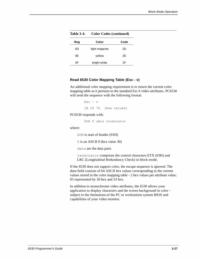
Block Mode Operation
6530 Programmer’s Guide 3-27
Read 6530 Color Mapping Table (Esc - v)
An additional color mapping requirement is to return the current color mapping table as it pertains to the standard Esc 6 video attributes. PC6530 will send the sequence with the following format:
Esc - v
1B 20 76 (hex values)
PC6530 responds with:
SOH 0 data terminator
where:
SOH is start of header (01H)
0 is an ASCII 0 (hex value 30)
data are the data pairs
terminator comprises the control characters ETX (03H) and LRC (Longitudinal Redundancy Check) in block mode.
If the 6530 does not support color, the escape sequence is ignored. The data field consists of 64 ASCII hex values corresponding to the current values stored in the color mapping table - 2 hex values per attribute value; 03 represented by 30 hex and 33 hex.
In addition to monochrome video attributes, the 6530 allows your application to display characters and the screen background in color - subject to the limitations of the PC or workstation system BIOS and capabilities of your video monitor.
0D light magenta 2D
0E yellow 2E
0F bright white 2F
Table 3-4. Color Codes (continued)
Reg Color Code
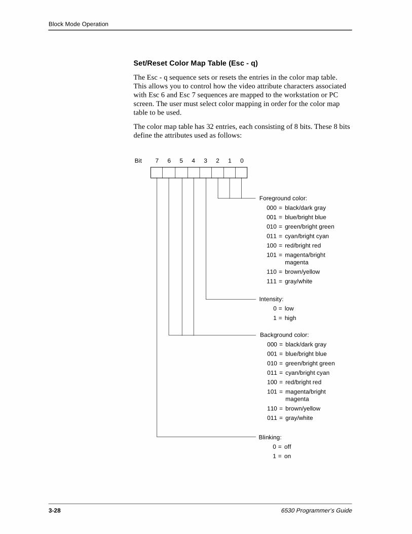
Block Mode Operation
3-28 6530 Programmer’s Guide
Set/Reset Color Map Table (Esc - q)
The Esc - q sequence sets or resets the entries in the color map table. This allows you to control how the video attribute characters associated with Esc 6 and Esc 7 sequences are mapped to the workstation or PC screen. The user must select color mapping in order for the color map table to be used.
The color map table has 32 entries, each consisting of 8 bits. These 8 bits define the attributes used as follows:
Bit 7 6 5 4 3 2 1 0
Foreground color:
000 = black/dark gray
001 = blue/bright blue
010 = green/bright green
011 = cyan/bright cyan
100 = red/bright red
101 = magenta/bright magenta
110 = brown/yellow
111 = gray/white
Intensity:
0 = low
1 = high
Background color:
000 = black/dark gray
001 = blue/bright blue
010 = green/bright green
011 = cyan/bright cyan
100 = red/bright red
101 = magenta/bright magenta
110 = brown/yellow
011 = gray/white
Blinking:
0 = off
1 = on
Block Mode Operation
6530 Programmer’s Guide 3-29
To specify the 8-bit entries in the table, your application must send pairs of ASCII encoded hexadecimal digits whose binary values represent the 8-bit patterns. For example, the hexadecimal digits 04 represent the following bit pattern:
0000 0100
This bit pattern sets the foreground color to red, the background color to black, the intensity to low, and blinking to off. You can use the 6530 configuration utility for the appropriate operating system to verify your color selection and color bit patterns. See the PC6530 user’s guide for information about the PC6530 configuration utility.
The lower 5 bits from the Esc 6 or Esc 7 attribute character are used as an index into the table, which is 0-based. For example, the # character, with a bit pattern of 00011 in the lower 5 bits, specifies the fourth entry in the table. The hexadecimal digits you set for the fourth table entry defines the actual video attributes displayed when the 6530 receives an Esc 6 # sequence.
The format of the Esc - q escape sequence is as follows:
Esc - pl;[p2];[p3] q pairs of hex digits
where:
p1 is an ASCII digit that specifies whether the color map table is to be set or reset. A value of 0 sets the color map table as defined by the pairs of hexadecimal digits following the escape sequence. A value of 1 resets the color map table to the default mapping scheme, which uses the colors selected in the 6530 initialization file. When the value of p1 is 1, the p2 and p3 parameters are ignored.
p2 is a series of ASCII digits, from 1 to 32, that specify the start-of-index location for the table entries to be set. For example, 1 specifies the first entry in the table. If you omit the parameter or specify a value outside the range of 1 - 32, the default value 1 is used.
p3 is a series of ASCII digits, from 1 to 32, that specify the end-of- index location for the table entries to be set. For example, 32 specifies the last entry in the table. If you omit the parameter or specify a value outside the range of 1 to 32, the default value 32 is used.
Block Mode Operation
3-30 6530 Programmer’s Guide
When p1 is set to 0, the escape sequence must be followed by the number of pairs of hexadecimal digits specified by the p2 and p3 range. For example, if p2 is set to 4 and p3 is set to 6, the escape sequence must be followed by three pairs of hexadecimal digits:
Esc - 0;4;6 q 04 40 17
The above sequence sets the fourth, fifth, and sixth entries in the color map table to the bit patterns defined by the hexadecimal digits 04, 40, and 17, respectively. To access those table entries and set the attributes on the screen, your application must send the following escape sequences:
Esc 6 # Sets attributes to fourth table entry (04)
Esc 6 $ Sets attributes to fifth table entry (40)
Esc 6 % Sets attributes to sixth table entry (17)
In the above example, the remaining table entries (1 through 3 and 7 through 32) were not set. Any Esc 6 or Esc 7 attribute character that accesses (indexes) these entries will use the default mapping scheme.
Read Color Mapping Table (Esc - v)
An additional color-mapping requirement is to return the current color mapping table as it pertains to the standard Esc 6 video attributes. The host sends the sequence with the following format:
Esc - v
1B 2D 76 (hex values)
The 6530 responds with:
SOH 0 data CR
where:
SOH is start of header (01H)
0 is an ASCII 0 (hex value 30)
data are the data pairs
CR is the control character (0DH) that terminates the message in conversational mode.
If the PC does not support color, the escape sequence is ignored. The data field consists of 64 ASCII hex values corresponding to the current values stored in the color mapping table - 2 hex values per attribute value; 03 represented by 30 hex and 33 hex.
Block Mode Operation
6530 Programmer’s Guide 3-31
Read Color Configuration (Esc - u)
The implementation of field-selectable color requires the reading and saving of additional color related information. Specifically, the PC6530 must be able to read the contents of the configurable registers before initializing the terminal for PATHWAY usage. The escape sequence has the following format:
Esc - u
1B 2D 75 (hex values)
The 6530 responds with:
SOH 1 cnt data CR
where:
SOH is start of header (01H)
1 is an ASCII 1 (hex value 31)
cnt is the data pair count
data are the data pairs
CR is the control character (0DH) that terminates the message in conversational mode.
If the PC does not support color or uses a CGA display adapter, the escape sequence will be ignored. Only EGA and VGA have programmable color registers. The cnt field will be 2 bytes of the number of color register pairs (ASCII readable hex) following in the data field. The data field will consist of pairs of ASCII hex values corresponding to the current values stored in the color registers. A color register pair will be register number plus register value. These values will be 2 bytes each in ASCII readable hex format. For example, register 12 (hex 0C), which contains the value of 5D will be stored as hex 30, hex 43, hex 35, hex 44. This constitutes one color register pair.
Block Mode Operation
3-32 6530 Programmer’s Guide
Set Color Configuration (Esc - t)
Once the host has read the color register configuration, it may determine the configuration must be changed. Changing the configuration requires an escape sequence of the following format: an escape, hyphen, 3 parameters separated by semicolons, lowercase t, and the color data information.
Esc - p1;p2;p3 t data
1B 2D p1 3B p2 3b p3 74 data (hex values)
where:
p1 sets (0 - hex 30) or resets (1 - hex 31) the color palette. If you are setting the color palette, use the values defined in data to the range applied by p2 through p3. If you are resetting the color palette, use the values set by the terminal at initialization. If reset, the second and third parameters may be omitted; they are ignored if sent.
p2 is the lower range of palette registers. Values are determined by the configuration (0-15 for EGA or VGA), a maximum of 2 bytes in ASCII decimal readable format. For example, register 9 would be hex 39; register 14 would be hex 31/hex 34.
p3 is the upper range of palette registers. Values are determined by the configuration (0-15 for EGA or VGA), a maximum of 2 bytes in ASCII decimal readable format. As in p2, register 9 would be hex 39; register 14 would be hex 31/hex 34.
data are the valid register values defined by PC documentation for the color requirements for EGA or VGA and other values defined by terminal documentation. These values are 2 bytes each in ASCII hex readable format. For example, a register value of 5E would be represented by hex 35, hex 45; and a register value of 8 would be represented by a hex 30, hex 38.
All data values are stored as ASCII hex values. Parameter values are stored as ASCII decimal values.
Set 6530 Color Mapping (Esc - x)
Enhanced color field support is available in the protect submode of block mode. This special field sequence has the following format:
Esc - p1 x
1B 2D p1 78 (hex values)
Block Mode Operation
6530 Programmer’s Guide 3-33
where:
p1 = ASCII 0 or 1 (hex 30 or hex 31)
0 sets standard 6530 field attribute mapping as specified by Esc 6 codes.
1 sets enhanced color field support mapping for all video pages.
When enhanced color field support mapping is set and a 6530 field video attribute is detected, the attribute is mapped according to the color mapping table but with any new color palette settings.
Start Enhanced Color Field (Esc ’)
The new start field order takes the form: escape, back quote, video attribute, data attribute one, data attribute two, pair count (two bytes representing the hex value of the count of bytes of data to follow. Two pairs of data are represented by a hex 30 followed by a hex 32, (ASCII 0 and ASCII 2).
Esc ’ vid1 da1 da2 pair cnt data
1B 60 vid1 da1 da2 cnt data (hex values)
where:
vid1, da1, and da2 have the same format and content as the conventional Start Field Extended (ESC ] ) command parameters.
The character ’ is a hex 60.
data refers to the IBM 3270-style attribute pairs 42H (foreground color) and 45H (background color). Either or both of these codes are valid values in the data field, followed by the hex values of the desired colors. Any other values are ignored.
Block Mode Operation
3-34 6530 Programmer’s Guide
Limitations
Whether implemented with CGA, EGA, or VGA BIOS, the 6530’s Enhanced Color Field control codes can only be invoked to use sixteen colors, regardless of the number of colors available in the BIOS specification. This means:
n When implemented with CGA, the 6530 is capable of controlling all available colors, including the designation of any of the first eight colors as background colors.
n When implemented with an EGA BIOS, a choice of any 16 of the 64 available colors must be made.
n When implemented with VGA BIOS, a choice of any 16 of the 256 colors available must be made. The 6530 uses VGA mode 3 (color text).
Enhanced Color Field control codes are constructed by first identifying whether the setting is for foreground (hex 42) or background (hex 45), then sending the register color value (in hex) added to a hex 20.
For example, to set the foreground color to light red (register 12) the data field should contain a hex 42 (select foreground color) followed by a hex 2C (0C+20H=2CH). To set the background color to magenta (register 05), the data field should contain a hex 45 (select background color) followed by a hex 25 (05+20H=25H).
Default colors are: foreground = red, background = black.
Read Screen With All Attributes (Esc Q)
The Esc Q sequence reads all data on the screen, including all attributes. This function is similar to the Esc = sequence; only those fields with the MDT set are sent. The format of the new sequence is:
Esc Q p1 p2 p3 p4
1B 51 parameters (hex values)
where:
p1 is the row specification of the starting buffer address
p2 is the column specification of the starting buffer address
p3 is the row specification of the ending buffer address
p4 is the column specification of the ending buffer address
The attribute locations are transmitted with the following format:
RS vid1 da1 da2 pair cnt data pairs
Block Mode Operation
6530 Programmer’s Guide 3-35
Note Note: The Esc Q sequence will transmit the data starting with an RS character if the enhanced color field is set in the protect submode; otherwise, an STX character is transmitted, similar to Esc =.
where:
RS is a hex 1E.
vid1, da1, and da2 have the same format and content as the conventional Start Field Extended (ESC ]) command parameters.
data refers to the IBM 3270-style attribute pairs 42H (foreground color) and 45H (background color). Either or both of these codes are valid values in the data field, followed by the hex values of the desired colors. Any other values are ignored.
See “Start Enhanced Color Field (Esc ’)” on page 3-33 for more details on the video and data attributes and the 3270 style attribute pairs that are contained in the pair count and data pairs.
Protect Submode This group of escape sequences applies only to protect submode. They perform functions such as entering and exiting protect submode, defining fields and the data type table, and resetting MDTs.
Note Because entering or exiting from protect submode clears all pages to blanks, the Esc W and the Esc X sequences should be issued in a separate call to the WRITE procedure before calls that write to display memory.
Enter Protect Submode (Esc W)
The Esc W sequence places the 6530 in protect submode. In that mode, the 6530 performs the following initialization procedures:
n Clear all pages to blanks (set default field)
n Set the video prior condition register to normal video for all pages
n Select page 1
n Display page 1
n Set the buffer address to line l, column 1 for all pages
Block Mode Operation
3-36 6530 Programmer’s Guide
n Set the cursor address to line 1, column 1 for all pages
n Lock the keyboard
n Clear the status line display
n Reset insert mode
n Initialize the data type table
n Disable local line editing (set Ctrl-Ins and Ctrl-Del to function keys)
Exit Protect Submode (Esc X)
The Esc X sequence exits protect submode and places the 6530 in nonprotect submode. When the 6530 enters nonprotect submode, it performs the following initialization procedures:
n Clear all pages to blanks
n Set the video prior condition register to normal video for all pages
n Select page 1
n Display page 1
n Set the buffer address to line 1, column 1 for all pages
n Set the cursor address to line 1, column 1 for all pages
n Lock the keyboard
n Clear the status line display
n Reset insert mode
n Enable local line editing (Ctrl-Ins and Ctrl-Del keys)
n Clear all horizontal tab stops
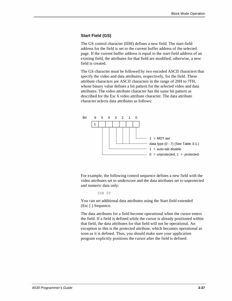
Block Mode Operation
6530 Programmer’s Guide 3-37
Start Field (GS)
The GS control character (lDH) defines a new field. The start-field address for the field is set to the current buffer address of the selected page. If the current buffer address is equal to the start-field address of an existing field, the attributes for that field are modified; otherwise, a new field is created.
The GS character must be followed by two encoded ASCII characters that specify the video and data attributes, respectively, for the field. These attribute characters are ASCII characters in the range of 20H to 7FH, whose binary value defines a bit pattern for the selected video and data attributes. The video attribute character has the same bit pattern as described for the Esc 6 video attribute character. The data attribute character selects data attributes as follows:
For example, the following control sequence defines a new field with the video attributes set to underscore and the data attributes set to unprotected and numeric data only:
1DH 0T
You can set additional data attributes using the Start field extended (Esc [ ) Sequence.
The data attributes for a field become operational when the cursor enters the field. If a field is defined while the cursor is already positioned within that field, the data attributes for that field will not be operational. An exception to this is the protected attribute, which becomes operational as soon as it is defined. Thus, you should make sure your application program explicitly positions the cursor after the field is defined.
Bit 6 5 4 3 2 1 0
1 = MDT set
data type (0 - 7) (See Table 3-1.)
1 = auto-tab disable
0 = unprotected, 1 = protected
1
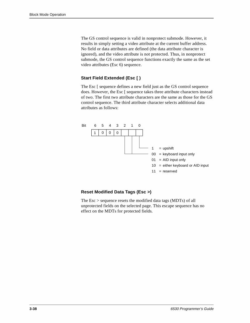
Block Mode Operation
3-38 6530 Programmer’s Guide
The GS control sequence is valid in nonprotect submode. However, it results in simply setting a video attribute at the current buffer address.No field or data attributes are defined (the data attribute character is ignored), and the video attribute is not protected. Thus, in nonprotect submode, the GS control sequence functions exactly the same as the set video attributes (Esc 6) sequence.
Start Field Extended (Esc [ )
The Esc [ sequence defines a new field just as the GS control sequence does. However, the Esc [ sequence takes three attribute characters instead of two. The first two attribute characters are the same as those for the GS control sequence. The third attribute character selects additional data attributes as follows:
Reset Modified Data Tags (Esc >)
The Esc > sequence resets the modified data tags (MDTs) of all unprotected fields on the selected page. This escape sequence has no effect on the MDTs for protected fields.
Bit 6 5 4 3 2 1 0
1 = upshift
00 = keyboard input only
01 = AID input only
10 = either keyboard or AID input
11 = reserved
1 0 0 0
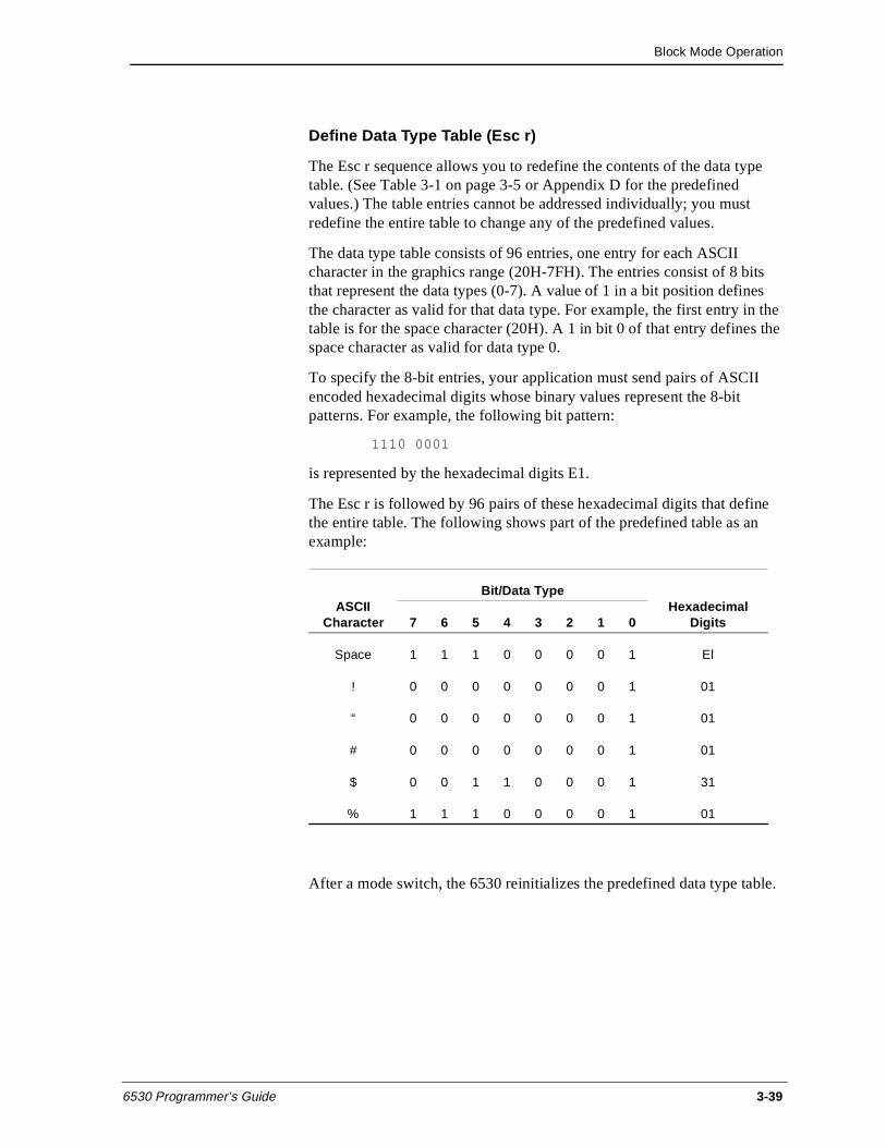
Block Mode Operation
6530 Programmer’s Guide 3-39
Define Data Type Table (Esc r)
The Esc r sequence allows you to redefine the contents of the data type table. (See Table 3-1 on page 3-5 or Appendix D for the predefined values.) The table entries cannot be addressed individually; you must redefine the entire table to change any of the predefined values.
The data type table consists of 96 entries, one entry for each ASCII character in the graphics range (20H-7FH). The entries consist of 8 bits that represent the data types (0-7). A value of 1 in a bit position defines the character as valid for that data type. For example, the first entry in the table is for the space character (20H). A 1 in bit 0 of that entry defines the space character as valid for data type 0.
To specify the 8-bit entries, your application must send pairs of ASCII encoded hexadecimal digits whose binary values represent the 8-bit patterns. For example, the following bit pattern:
1110 0001
is represented by the hexadecimal digits E1.
The Esc r is followed by 96 pairs of these hexadecimal digits that define the entire table. The following shows part of the predefined table as an example:
After a mode switch, the 6530 reinitializes the predefined data type table.
ASCII Character
Bit/Data TypeHexadecimal
Digits 7 6 5 4 3 2 1 0
Space 1 1 1 0 0 0 0 1 El
! 0 0 0 0 0 0 0 1 01
“ 0 0 0 0 0 0 0 1 01
# 0 0 0 0 0 0 0 1 01
$ 0 0 1 1 0 0 0 1 31
% 1 1 1 0 0 0 0 1 01
Block Mode Operation
3-40 6530 Programmer’s Guide
Define Data Type Table Extended (Esc-r)
The Esc - r sequence allow you to redefine the data type table for a range of characters. (See Table 3-1 on page 3-5 or Appendix D for the predefined values.) This escape sequence also allows you to redefine the data type table for the G1 set. The format of the escape sequence is as follows:
Esc - p1;p2 r
where:
p1 is a series of ASCII digits that specify the starting character code for the following data type entries. The default value is 1.
p2 is a series of ASCII digits that specify the ending character code for the following data type entries. The default value is 192 (last character in the G1 set).
Valid parameters are in the range of 1 to 192. Out of range values default to 192. The range 1 to 96 corresponds to the ASCII graphics characters (G0 set), starting with the space character (20H) through the DEL symbol (7FH). The range 97 to 192 corresponds to the G1 set (80H through FFH).
The escape sequence is followed by an entry for each character specified by the range of the two parameters. The entries (pairs of hexadecimal digits) have the same format as those described for the ESC r sequence.
After a power up, hard reset, mode switch, or reinitialization (ESC q), the terminal restores the predefined data type table.
Set 40-character line width (Esc 8)
Sets the screen format to a line width of 40 characters. For use with TS530 terminals only (not PC6530).
Set 80-character line width (Esc 9)
Sets the screen format to a line width of 80 characters. For use with TS530 terminals only (not PC6530).
Set 40-character screen width (Esc t)
Sets the screen width to 40 characters. For use with TS530 terminals only (not PC6530).
Block Mode Operation
6530 Programmer’s Guide 3-41
EM3270 Submode The Esc - m command is used to switch in and out of EM3270 submode. This command exits EM3270 without invoking any reinitialization procedure. Re-initialization must be specifically invoked through a mode switch, or by an Esc q sequence.
The 6530 can be switched from EM3270 submode to either block or conversational mode. For more details on switching to conversational mode, see “Switch from block to conversational mode” on page 1-14.
Note Several escape sequences and cursor motion keys operate differently in EM3270 mode than in other modes. See “EM3270 Support” on page 3-67.
Read Page This group of escape sequences causes the 6530 to transmit all or portions of the selected page. These operations do not affect the current buffer address. The actual data transmitted and the format of the data depends on the submode in effect.
In nonprotect submode, the text transmitted consists of displayable data, along with any video attributes specified by Esc 6 sequences (the attribute character transmitted is 40H-based). Trailing spaces on a line are not transmitted; a CR character is used to delimit lines. Each line on the page is transmitted; if the entire line is blank, only a CR is sent. The following example shows the general format of transmitted data:
displayable data (text for line 1)
.
.
.
Esc 6
attribute character (define video attributes)
displayable data (more text for line 1)
.
.
.
CR (end of nonblank data for line 1)
displayable data (text for line 2)
.
.
.
etc.
Block Mode Operation
3-42 6530 Programmer’s Guide
In protect submode, the text transmitted consists of data stored in unprotected fields (and, in some cases, protected fields if their MDTs are set). The content of each field is preceded by a DC1 sequence that specifies the address for that field. This address is the address of the first unprotected position in the respective field; thus, it is the address of the video attribute for that field plus one. Trailing spaces in a field are not transmitted. If a field contains only spaces, only the field separator (DC1 plus the 2-character address) is transmitted. Esc 6 sequences are handled the same way as in nonprotect submode. The following example shows the general format of transmitted data:
With some of the escape sequences, you can select a portion of the page to be read. In these cases, the transmission begins at the specified read start address and continues through a specified read end address on the selected page.
In protect submode, the transmission starts with the first field that begins at or after the read start address. (The beginning of the field is the first position after the video attribute for that field.) Thus, if the specified read start address is not at the beginning of a field, the transmission starts at the next field. The transmission stops at the first end of field that is equal to or greater than the read end address. (The end of a field is the last position in that field, before the video attribute of the next field.) Thus, if the specified read end address is within a field, the transmission continues past this address to the end of the field and stops.
The following examples illustrate some of the various cases that you may encounter. (The examples assume that the MDTs are set in all fields shown.)
DC1 address (address of first unprotected field)
displayable data (text for first unprotected field)
.
.
.
DC1
address (address of next unprotected field)
displayable data (text for next unprotected field)
.
.
.
etc.
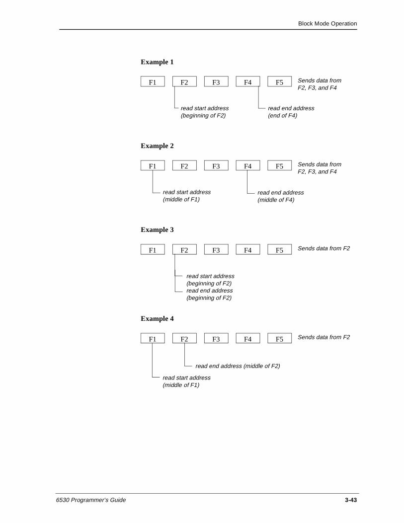
Block Mode Operation
6530 Programmer’s Guide 3-43
Example 1
Example 2
Example 3
Example 4
F1 F2 F3 F5F4 Sends data from F2, F3, and F4
read start address (beginning of F2)
read end address (end of F4)
F1 F2 F3 F5F4 Sends data from F2, F3, and F4
read start address (middle of F1)
read end address (middle of F4)
F1 F2 F3 F5F4 Sends data from F2
read start address (beginning of F2)read end address(beginning of F2)
F1 F2 F3 F5F4 Sends data from F2
read start address (middle of F1)
read end address (middle of F2)
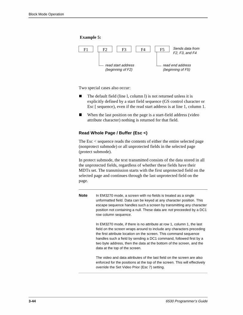
Block Mode Operation
3-44 6530 Programmer’s Guide
Example 5:
Two special cases also occur:
n The default field (line l, column l) is not returned unless it is explicitly defined by a start field sequence (GS control character or Esc [ sequence), even if the read start address is at line 1, column 1.
n When the last position on the page is a start-field address (video attribute character) nothing is returned for that field.
Read Whole Page / Buffer (Esc <)
The Esc < sequence reads the contents of either the entire selected page (nonprotect submode) or all unprotected fields in the selected page (protect submode).
In protect submode, the text transmitted consists of the data stored in all the unprotected fields, regardless of whether these fields have their MDTs set. The transmission starts with the first unprotected field on the selected page and continues through the last unprotected field on the page.
Note In EM3270 mode, a screen with no fields is treated as a single unformatted field. Data can be keyed at any character position. This escape sequence handles such a screen by transmitting any character position not containing a null. These data are not preceeded by a DC1 row column sequence.
In EM3270 mode, if there is no attribute at row 1, column 1, the last field on the screen wraps around to include any characters preceding the first attribute location on the screen. This command sequence handles such a field by sending a DC1 command, followed first by a two byte address, then the data at the bottom of the screen, and the data at the top of the screen.
The video and data attributes of the last field on the screen are also enforced for the positions at the top of the screen. This will effectively override the Set Video Prior (Esc 7) setting.
F1 F2 F3 F5F4 Sends data from F2, F3, and F4
read start address (beginning of F2)
read end address (beginning of F5)
Block Mode Operation
6530 Programmer’s Guide 3-45
Read with Address (Esc =)
The Esc = sequence reads a specified area of the selected page by using normal addressing format described in “Cursor and Buffer Addressing” on page 3-13. The format for the escape sequence is:
Esc = start-row start-column end-row end-column
where:
start-row and start-column are encoded ASCII characters that specify the beginning location of the area to be read (read start address).
end-row and end-column are encoded ASCII characters that specify the ending location of the area to be read (read end address).
For example, the following sequence reads an area starting at row 5, column 5 and ending at row 10, column 10:
1BH = $ $ ) )
If the read end address is less than the read start address, an empty block is transmitted.
In nonprotect submode, the 6530 transmits the entire area specified by the read start address and read end address (inclusive).
In protect submode, the 6530 transmits data only from fields that have their MDTs set and are within the specified area as described in “Fields and Field Attributes (Protect Submode)” on page 3-1.
Notes Both unprotected and protected fields within the specified area are transmitted if these fields have their MDTs set. If no fields within the area have their MDTs set, an empty block is transmitted.
In EM3270 mode, this sequence:
Stores nulls rather than spaces in the screen buffer.
A screen with no fields is treated as a single unformatted field. Data may be keyed at any character position. This escape sequence handles such a screen by transmitting any character position not containing a null. These data are not preceded by a DC1 row column sequence.
If there is no attribute at row 1, column 1, the last field on the screen wraps around to include any characters preceding the first attribute location on the screen. This command sequence handles such a field by sending a DC1 command, followed first by a two byte address, then the data at the bottom of the screen, and the data at the top of the screen.
Block Mode Operation
3-46 6530 Programmer’s Guide
The video and data attributes of the last field on the screen are also enforced for the positions at the top of the screen. This effectively overrides the Set Video Prior (Esc 7) setting.
Read with Address Extended (Esc - J)
The Esc - J sequence reads a specified area of the selected page by using either the normal or extended addressing format described in “Cursor and Buffer Addressing” on page 3-13. The format for the escape sequence is as follows:
Esc - start-row ; start-column ; end-row ; end-column J
where:
start-row and start-column are decimal numbers that specify the beginning location for the area to be read (read start address).
end-row and end-column are decimal numbers that specify the ending location for the areas to be read (read end address).
J terminates the sequence.
For example the following sequence reads an area starting at row 5, column 5 and ending at row 10, column 72;
IBH - 5;5;10;72 J
The Esc - J sequence functions exactly like the Esc = sequence, except for the difference in format.
Read with Address All (Esc ])
The Esc ] sequence reads a specified area of the selected page with normal addressing format as described in “Cursor and Buffer Addressing” on page 3-13. The format for the escape sequence is:
Esc ] start-row start-column end-row end-column
where:
start-row and start-column are encoded ASCII characters that specify the beginning location of the area to be read (read start address).
end-row and end-column are encoded ASCII characters that specify the ending location of the area to be read (read end address).
Block Mode Operation
6530 Programmer’s Guide 3-47
For example, the following sequence reads an area starting at row 5, column 5 and ending at row 10, column 10:
1BH ]$ $ ) )
In nonprotect submode, the Esc ] sequence functions exactly like the Esc = sequence.
In protect submode, the Esc ] sequence reads all fields in the specified area, regardless of whether their MDTs are set. This includes both protected and unprotected fields.
Note In EM3270 mode, this sequence:
Stores nulls rather than spaces in the screen buffer.
A screen with no fields is treated as a single unformatted field. Data may be keyed at any character position. This escape sequence handles such a screen by transmitting any character position not containing a null. These data are not preceded by a DC1 row column sequence.
If there is no attribute at row 1, column 1, the last field on the screen wraps around to include any characters preceding the first attribute location on the screen. This command sequence handles such a field by sending a DC1 command, followed first by a two byte address, then the data at the bottom of the screen, and the data at the top of the screen.
The video and data attributes of the last field on the screen are also enforced for the positions at the top of the screen. This effectively overrides the Set Video Prior (Esc 7) setting.
Read with Address All Extended (Esc - K)
The Esc - K sequence reads a specified area of the selected page with extended addressing format as described in “Cursor and Buffer Addressing” on page 3-13. The format for the escape sequence is as follows:
Esc - start-row ; start-column ; end-row ; end-column K
where:
start-row and start-column are decimal numbers that specify the beginning location for the area to be read (read start address).
Block Mode Operation
3-48 6530 Programmer’s Guide
end-row and end-column are decimal numbers that specify the ending location for the areas to be read (read end address).
K terminates the sequence.
For example, the following sequence reads an area starting at row 5, column 5 and ending at row 10, column 72;
1BH - 5;5;10;72 K
The Esc - K sequence functions like the Esc ] sequence, except for the difference in format.
Clear Display Memory
This group of escape sequences clears or erases all or parts of the selected page.
Clear Memory to Spaces (Esc I)
The Esc I sequence clears a specified area of the selected page. The Esc I sequence uses normal addressing format as described in “Cursor and Buffer Addressing” on page 3-13. The escape sequence has the following format:
Esc I start-row start-column end-row end-column
where:
start-row and start-column are encoded ASCII characters that specify the beginning location of the area to be cleared (start address).
end-row and end-column are encoded ASCII characters that specify the ending location of the area to be cleared (end address).
The escape sequence blank fills the entire area specified by the start address and end address (inclusive). The operation does not cross page boundaries. If the end address is less than the start address, no operation occurs.
In protect submode, if a field-start address falls within the specified area, that field is deleted. If, as a result of the deletion, the cursor is positioned in a protected field, the 6530 performs a forward tab to move the cursor to the next unprotected position on that page.
Note In EM3270 mode, this sequence stores nulls rather than spaces in the screen buffer.
Block Mode Operation
6530 Programmer’s Guide 3-49
Clear Memory to Spaces Extended (Esc - I)
The Esc - I sequence clears a specified area of the selected page, with extended addressing format as described in “Cursor and Buffer Addressing” on page 3-13. The escape sequence has the following format:
Esc - start-row ; start-column ; end-row ; end-column I
where:
start-row and start-column are decimal numbers that specify the beginning location for the area to be cleared (start address).
end-row and end-column are decimal numbers that specify the ending location for the area to be cleared (end address).
Other than the difference in format, this escape sequence functions exactly the same as the Esc I sequence.
Erase to End of Page (Esc J)
The Esc J sequence erases characters on the selected page, starting from the current buffer address to the end of the page.
In protect submode, only characters in the unprotected positions are erased. Thus, the contents of all protected fields and all the start-field video attributes remain intact. The contents of unprotected fields are erased, but the fields themselves remain defined.
Note In EM3270 mode, this sequence stores nulls rather than spaces in the screen buffer.
Erase to End of Line/Field (Esc K)
The Esc K sequence erases characters on the selected page, starting from the current buffer address to the end of the line (nonprotect submode) or to the end of the field (protect submode).
In protect submode, the contents of a field are erased, regardless of whether the field is protected or unprotected. If the current buffer address is equal to the field-start address, the field's video attribute character is erased, but the field remains defined. Thus, no field definitions are deleted by this operation.
Block Mode Operation
3-50 6530 Programmer’s Guide
Note In EM3270 mode, this sequence stores nulls rather than spaces in the screen buffer.
Editing This group of escape sequences performs editing operations such as inserting and deleting lines and characters. These operations do not affect the current buffer address.
Insert Line (Esc L)
The Esc L sequence moves the display data down one line, starting at the line containing the current buffer address. This results in the insertion of a blank line at the buffer address and the deletion of the bottom line on the page. If you want to save the data on the bottom line, your application must read it and save it prior to issuing the Esc L sequence.
In protect submode, any field whose start-field address is located in the bottom line is deleted. If the cursor is positioned into a protected field as a result of the line insertion, the 6530 performs a forward tab to move the cursor to the next unprotected position on the page.
Note In EM3270 mode, this sequence stores nulls rather than spaces in the new line.
Delete Line (Esc M)
The Esc M sequence deletes the line containing the current buffer address. This results in moving subsequent lines up one line and blank filling the bottom line.
In protect submode, any field whose start-field address is located in the deleted line is also deleted. If the cursor is positioned into a protected field as a result of the line deletion, the 6530 performs a forward tab to move the cursor to the next unprotected position on the page.
Note In EM3270 mode, this sequence stores nulls rather than spaces in line 24.
Block Mode Operation
6530 Programmer’s Guide 3-51
Insert Character (Esc O)
The Esc O sequence inserts a blank space at the current buffer address. This results in moving all subsequent characters in the line (nonprotect submode) or in the field (protect submode) one position to the right. The right-most (last) character in the line or field is lost.
In the case of a multiline field in protect submode, the characters wrap around to the next line. Characters are inserted in unprotected fields only. If the current buffer address is within a protected field, no insert operation occurs.
Note In EM3270 mode, this sequence stores a null rather than a space in the new character position.
Delete Character (Esc P)
The Esc P sequence deletes the character at the current buffer address. This results in moving all subsequent characters in the line (nonprotect submode) or in the field (protect submode) one position to the left. The right-most (last) character position in the line or field is blank filled.
In the case of a multiline field in protect submode, the delete wraps around from line to line. Characters are deleted from unprotected fields only. If the buffer address is within a protected field, no delete operation occurs.
Note In EM3270 mode, this sequence stores a null rather than a space in the last character position of the field.
Configuration Values
This group of escape sequences reads or sets values for configuration parameters. These include parameters for terminal operation if the workstation or PC and parameters for an attached printer. Each parameter is specified by a code/value pair, where the code identifies the configuration item and the value specifies the selection for the item. Table 3-5 on page 3-52 lists the terminal configuration parameters and shows the code and possible values for each. See Chapter 1 for an explanation of these parameters.
The Read Terminal Configuration sequence (Esc ?) followed by a set of code/value pairs causes the 6530 to transmit the current values for the terminal configuration parameters to the host.
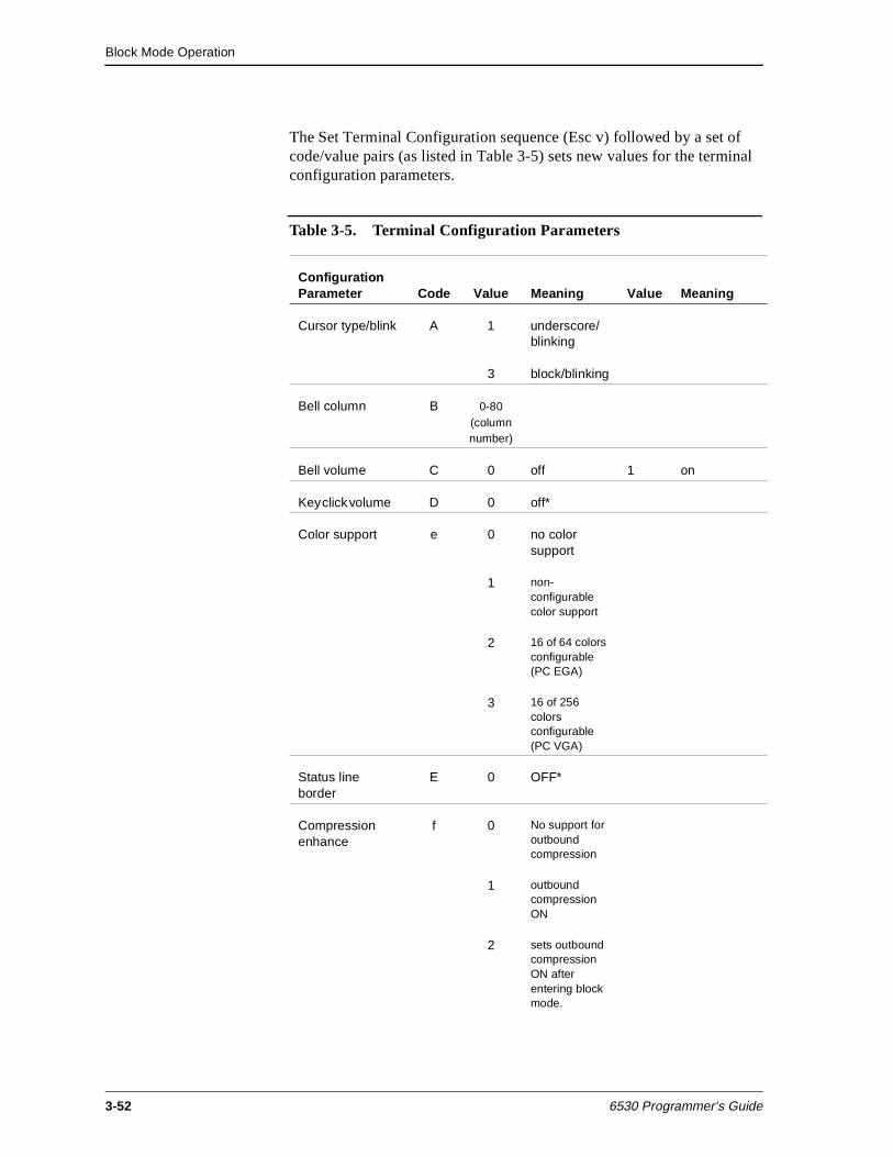
Block Mode Operation
3-52 6530 Programmer’s Guide
The Set Terminal Configuration sequence (Esc v) followed by a set of code/value pairs (as listed in Table 3-5) sets new values for the terminal configuration parameters.
Table 3-5. Terminal Configuration Parameters
Configuration Parameter Code Value Meaning Value Meaning
Cursor type/blink A 1 underscore/blinking
3 block/blinking
Bell column B 0-80 (columnnumber)
Bell volume C 0 off 1 on
Key click volume D 0 off*
Color support e 0 no color support
1 non-configurable color support
2 16 of 64 colors configurable (PC EGA)
3 16 of 256 colors configurable (PC VGA)
Status line border
E 0 OFF*
Compression enhance
f 0 No support for outbound compression
1 outbound compression ON
2 sets outbound compression ON after entering block mode.
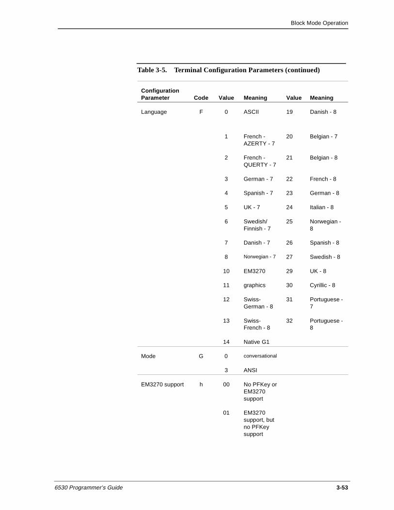
Block Mode Operation
6530 Programmer’s Guide 3-53
Language F 0 ASCII 19 Danish - 8
1 French - AZERTY - 7
20 Belgian - 7
2 French - QUERTY - 7
21 Belgian - 8
3 German - 7 22 French - 8
4 Spanish - 7 23 German - 8
5 UK - 7 24 Italian - 8
6 Swedish/Finnish - 7
25 Norwegian - 8
7 Danish - 7 26 Spanish - 8
8 Norwegian - 7 27 Swedish - 8
10 EM3270 29 UK - 8
11 graphics 30 Cyrillic - 8
12 Swiss-German - 8
31 Portuguese - 7
13 Swiss-French - 8
32 Portuguese - 8
14 Native G1
Mode G 0 conversational
3 ANSI
EM3270 support h 00 No PFKey or EM3270 support
01 EM3270 support, but no PFKey support
Table 3-5. Terminal Configuration Parameters (continued)
Configuration Parameter Code Value Meaning Value Meaning
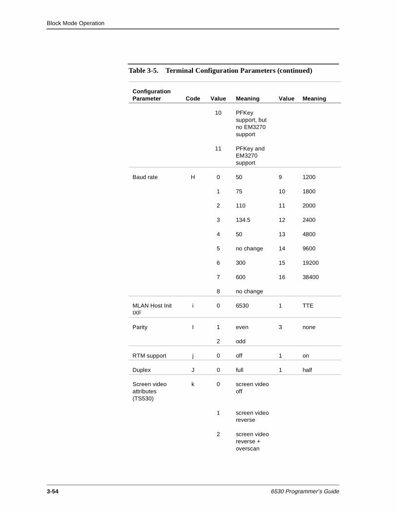
Block Mode Operation
3-54 6530 Programmer’s Guide
10 PFKey support, but no EM3270 support
11 PFKey and EM3270 support
Baud rate H 0 50 9 1200
1 75 10 1800
2 110 11 2000
3 134.5 12 2400
4 50 13 4800
5 no change 14 9600
6 300 15 19200
7 600 16 38400
8 no change
MLAN Host Init IXF
i 0 6530 1 TTE
Parity I 1 even 3 none
2 odd
RTM support j 0 off 1 on
Duplex J 0 full 1 half
Screen video attributes (TS530)
k 0 screen video off
1 screen video reverse
2 screen video reverse + overscan
Table 3-5. Terminal Configuration Parameters (continued)
Configuration Parameter Code Value Meaning Value Meaning
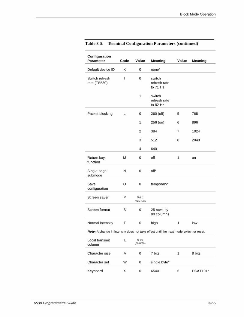
Block Mode Operation
6530 Programmer’s Guide 3-55
Default device ID K 0 none*
Switch refresh rate (TS530)
l 0 switch refresh rate to 71 Hz
1 switch refresh rate to 82 Hz
Packet blocking L 0 260 (off) 5 768
1 256 (on) 6 896
2 384 7 1024
3 512 8 2048
4 640
Return key function
M 0 off 1 on
Single-page submode
N 0 off*
Save configuration
O 0 temporary*
Screen saver P 0-20 minutes
Screen format S 0 25 rows by 80 columns
Normal intensity T 0 high 1 low
Note: A change in intensity does not take effect until the next mode switch or reset.
Local transmit column
U 0-80 (column)
Character size V 0 7 bits 1 8 bits
Character set W 0 single byte*
Keyboard X 0 654X* 6 PCAT101*
Table 3-5. Terminal Configuration Parameters (continued)
Configuration Parameter Code Value Meaning Value Meaning
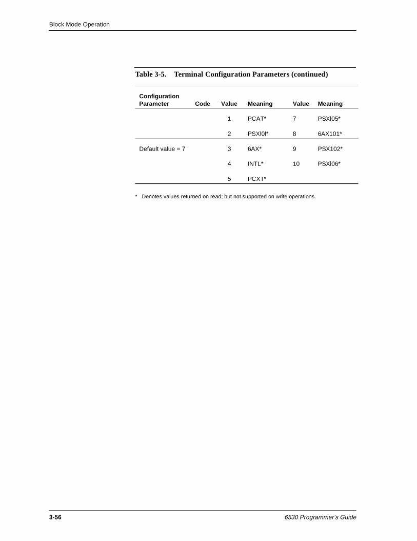
Block Mode Operation
3-56 6530 Programmer’s Guide
* Denotes values returned on read; but not supported on write operations.
1 PCAT* 7 PSXl05*
2 PSXl0l* 8 6AX101*
Default value = 7 3 6AX* 9 PSX102*
4 INTL* 10 PSXl06*
5 PCXT*
Table 3-5. Terminal Configuration Parameters (continued)
Configuration Parameter Code Value Meaning Value Meaning
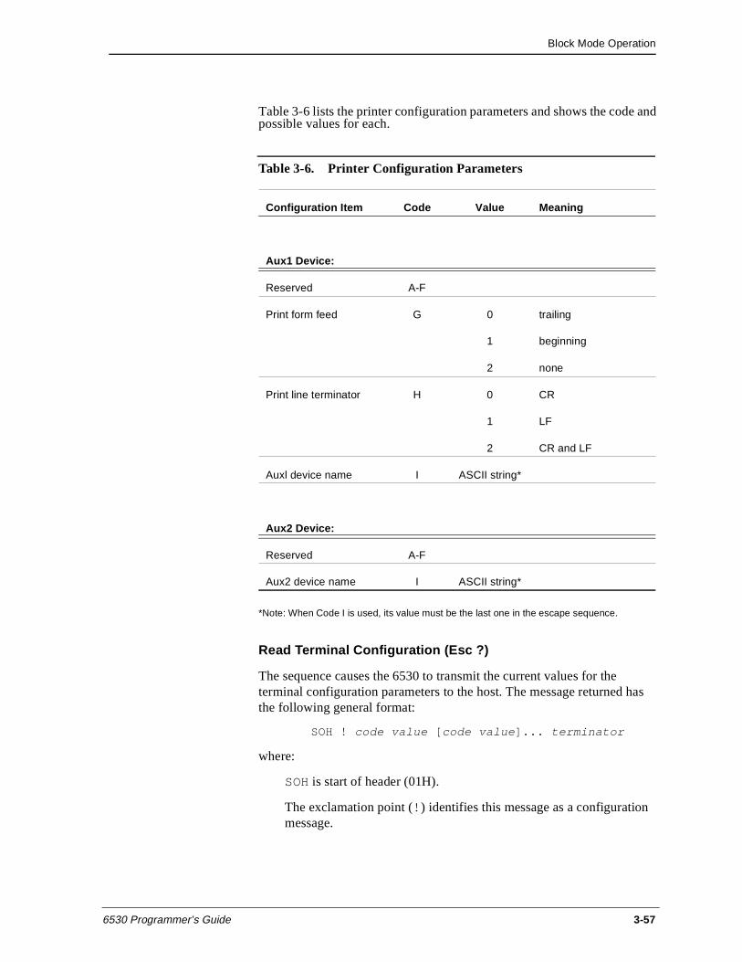
Block Mode Operation
6530 Programmer’s Guide 3-57
Table 3-6 lists the printer configuration parameters and shows the code andpossible values for each.
*Note: When Code I is used, its value must be the last one in the escape sequence.
Read Terminal Configuration (Esc ?)
The sequence causes the 6530 to transmit the current values for the terminal configuration parameters to the host. The message returned has the following general format:
SOH ! code value [code value]... terminator
where:
SOH is start of header (01H).
The exclamation point (!) identifies this message as a configuration message.
Table 3-6. Printer Configuration Parameters
Configuration Item Code Value Meaning
Aux1 Device:
Reserved A-F
Print form feed G 0 trailing
1 beginning
2 none
Print line terminator H 0 CR
1 LF
2 CR and LF
Auxl device name I ASCII string*
Aux2 Device:
Reserved A-F
Aux2 device name I ASCII string*
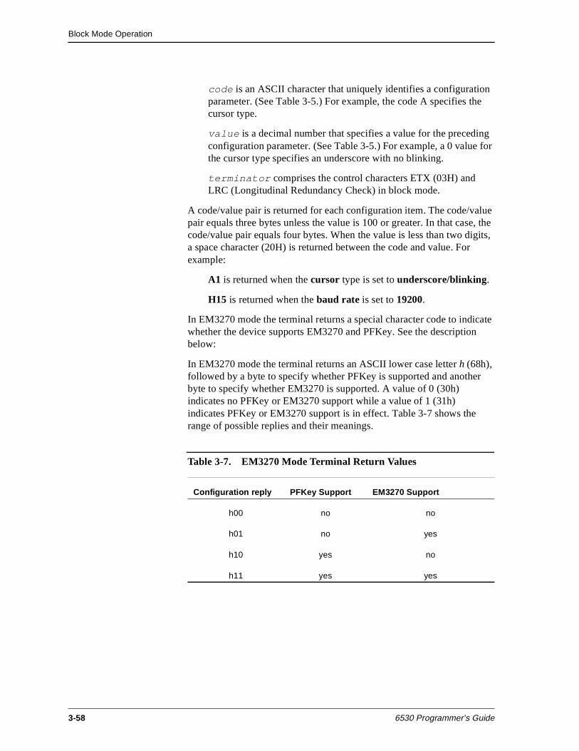
Block Mode Operation
3-58 6530 Programmer’s Guide
code is an ASCII character that uniquely identifies a configuration parameter. (See Table 3-5.) For example, the code A specifies the cursor type.
value is a decimal number that specifies a value for the preceding configuration parameter. (See Table 3-5.) For example, a 0 value for the cursor type specifies an underscore with no blinking.
terminator comprises the control characters ETX (03H) and LRC (Longitudinal Redundancy Check) in block mode.
A code/value pair is returned for each configuration item. The code/value pair equals three bytes unless the value is 100 or greater. In that case, the code/value pair equals four bytes. When the value is less than two digits, a space character (20H) is returned between the code and value. For example:
A1 is returned when the cursor type is set to underscore/blinking.
H15 is returned when the baud rate is set to 19200.
In EM3270 mode the terminal returns a special character code to indicate whether the device supports EM3270 and PFKey. See the description below:
In EM3270 mode the terminal returns an ASCII lower case letter h (68h), followed by a byte to specify whether PFKey is supported and another byte to specify whether EM3270 is supported. A value of 0 (30h) indicates no PFKey or EM3270 support while a value of 1 (31h) indicates PFKey or EM3270 support is in effect. Table 3-7 shows the range of possible replies and their meanings.
Table 3-7. EM3270 Mode Terminal Return Values
Configuration reply PFKey Support EM3270 Support
h00 no no
h01 no yes
h10 yes no
h11 yes yes
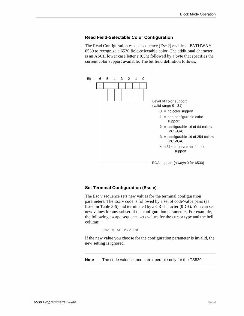
Block Mode Operation
6530 Programmer’s Guide 3-59
Read Field-Selectable Color Configuration
The Read Configuration escape sequence (Esc ?) enables a PATHWAY 6530 to recognize a 6530 field-selectable color. The additional character is an ASCII lower case letter e (65h) followed by a byte that specifies the current color support available. The bit field definition follows.
Set Terminal Configuration (Esc v)
The Esc v sequence sets new values for the terminal configuration parameters. The Esc v code is followed by a set of code/value pairs (as listed in Table 3-5) and terminated by a CR character (0DH). You can set new values for any subset of the configuration parameters. For example, the following escape sequence sets values for the cursor type and the bell column:
Esc v A0 B72 CR
If the new value you choose for the configuration parameter is invalid, the new setting is ignored.
Note The code values k and l are operable only for the TS530.
Bit 6 5 4 3 2 1 0
Level of color support (valid range 0 - 31)
0 = no color support
1 = non-configurable color support
2 = configurable 16 of 64 colors(PC EGA)
3 = configurable 16 of 254 colors(PC VGA)
4 to 31= reserved for futuresupport
1
EOA support (always 0 for 6530)
Block Mode Operation
3-60 6530 Programmer’s Guide
Read I/0 Device Configuration (Esc y)
The Esc y sequence causes the 6530 to transmit the current values for the Auxl and Aux2 device configuration parameters to the host. The Esc y must be followed by a T and a decimal number that identifies the device (2 for the Auxl device and 3 for the Aux2 device). For example:
Esc y T2
The message returned has the following general format:
SOH !code value [code value]... terminator
where:
SOH is a control character (01H) that acts as a start of header for messages returned to the host.
The exclamation point (!) identifies this message as a configuration message.
code is an ASCII character that uniquely identifies a configuration parameter. (See Table 3-6 on page 3-57.)
value is either a decimal number or string that specifies a value for the preceding configuration parameter. (See Table 3-6 on page 3-57.)
terminator comprises the control characters ETX (03H) and LRC (Longitudinal Redundancy Check) in block mode.
A code/value per is returned for each configuration item. Each code/value pair equals three bytes.
Set I/0 Device Configuration (Esc x)
The Esc x sequence sets new configuration values for the Auxl or Aux2 devices. The escape sequence has the following general format:
Esc xT device code value [code value] ... CR
where:
The T is required before device, which specifies the type of device. This must be either 2 for the Aux1 device or 3 for the Aux2 device.
code is an ASCII character that uniquely identifies a configuration parameter. (See Table 3-6 on page 3-57.)
value is either a decimal number or string that specifies a value for the preceding configuration parameter. (See Table 3-6 on page 3-57.)
Block Mode Operation
6530 Programmer’s Guide 3-61
CR is a control character (0DH) that terminates the sequence.
The following example sets the form feed for a printer associated with the Auxl device:
Esc x T2 G1 CR
Read String Configuration Parameter (Esc - d)
The Esc - d sequence causes the 6530 to transmit the current values for the configuration parameters with string values. The escape sequence has the following format:
Esc - pn d
where:
pn is an ASCII digit from 0 through 7 that specifies the parameter(s) to be read as follows:
0 = read all seven string parameters
1 = read window name parameter (string value up to 26 characters)
2 = read resource name parameter (string value up to 34 characters)
3 = read host name parameter (string value up to 8 characters)
4 = read start up string parameter (string value up to 128 characters)
5 = read transmit line parameter (string value up to 80 characters)
6 = read device name parameter (string value up to 8 characters)
7 = read session name parameter (string value up to 16 characters)
If the pn parameter is missing or greater than 7, all seven parameter values are returned. The message returned has the following general format:
SOH ( string DC2 [string DC2]... terminator
where:
SOH is a control character (01H) that acts as a start of header for messages returned to the host.
Block Mode Operation
3-62 6530 Programmer’s Guide
The left parenthesis ( ( ) identifies this message as a string value configuration message.
string is the ASCII character string value for the parameter(s) read. When all seven parameters are returned, they are returned in the order specified by pn as listed above.
DC2 is a control character (l2H) that acts as a delimiter for the string values.
terminator comprises the control characters ETX (03H) and LRC (Longitudinal Redundancy Check) in block mode.
Set String Configuration Parameter (Esc - c)
The Esc - c sequence sets new values for configuration parameters with string values. The escape sequence has the following format:
Esc - pn c string DC2 [string DC2] ... CR
where:
pn is an ASCII digit from 0 through 7 that specifies the parameter(s) to be set. These are the same as the pn values for the Esc - d sequence. If the pn parameter is missing or greater than 7, values for all seven parameters are expected following the ’c’.
string is the ASCII character string value for the parameter(s) to be set. When all seven parameters are set, their string values must be listed in the order specified by pn. The 6530 truncates any string values that exceed the maximum length allowed for that parameter.
DC2 is a control character (12H) that acts as a delimiter for the string values.
CR is a control character (0DH) that terminates the message.
Block Mode Operation
6530 Programmer’s Guide 3-63
Read VTLAUNCH 6530 Configuration Parameter ( Esc - g )
The Esc - g escape sequence provides a mechanism for the host to identify the connected 6530 in Virtual Terminal Launch (VTLAUNCH). Host programs that have knowledge of various emulators can use this information to provide extended support for those recognizable devices.
The Esc - g sequence causes the 6530 to transmit the current string values of its supported configuration parameters. Only parameters 2 (terminal type) and 3 (operating system version) are supported by the 6530.
A syntax error in the escape sequence causes the 6530 to ignore the sequence and return no response.
The Escape sequence has the following format:
Esc - pn g
where:
pn is the parameter number (an ASCII numeric character)
0 = all 6530 parameters in order 1-6
2 = 6530 type
3 = operating system version
The return message has the following format:
SOH ( string DC2 [string DC2]... terminator
where:
SOH is a control character (01H) that acts as a start of header for messages returned to the host.
( is left parenthesis (28H).
string is the ASCII character string value for the parameter(s) to be set. When all seven parameters are set, their string values must be listed in the order specified by pn. The 6530 truncates any string values that exceed the maximum length allowed for that parameter.
DC2 is a control character (12H) that acts as a delimiter for the string values.
terminator comprises the control characters ETX (03H) and LRC (Longitudinal Redundancy Check) in block mode.
Block Mode Operation
3-64 6530 Programmer’s Guide
RTM Support The 6530 supports Response Time Measurement (RTM): collecting response time statistics, accepting commands to set up RTM collection parameters, and accepting commands that solicit a response containing the RTM data collected.
Response Time Measurement is implemented by using a configurable number of counters (buckets) which count the number of times that measured response intervals fall within configurable time range boundaries (bucket boundaries) associated with each counter.
The response interval is the measured length of time between the start and stop timing events which are configurable as either:
the press of a function key (start) and the receipt of the first resulting character from the host (stop),
or
the press of a function key (start) and the receipt of the keyboard unlock command (stop).
The time measurements is reported to the nearest 100 milliseconds and is accurate within 10 percent or less.
Bucket boundaries consist of a lower boundary and upper boundary, specified in centiseconds. The count held in the bucket is incremented by one when a response interval measurement falls within the bucket boundaries.
The configured number of buckets will contiguously cover the time range from 0 to infinity. Buckets are actually defined by specifying one or more partitions in that range, rather than explicitly specifying the start and end value for each bucket.
For example, specifying one partition at 100 centiseconds causes two buckets to be created - one that counts the occurrence of response intervals in the range of 0 to 100 centiseconds and a second bucket that counts the occurrence of response intervals greater than 100 centiseconds.
RTM recording of response intervals is enabled on entry to block mode and also each time the RTM Controls are reset. The RTM Controls for terminals include definition of the response interval start/stop events, the number of buckets, and the bucket boundaries (specified as partitions).
The default RTM control settings are:
RTM response interval start/stop events are any function key press (start) and the receipt of the keyboard unlock command (stop).
The number of buckets is 5.
Block Mode Operation
6530 Programmer’s Guide 3-65
Five buckets will be configured by setting 4 bucket partitions at 200 csec, 400 csec, 1000 csec, 2000 csec, which results in the following buckets:
Bucket: B1 B2 B3 B4 B5
Bucket boundaries: 0....2s....4s....10s....20s....infinity
The 6530 also supports RTM Definite Response. Definite Response enables the host to elicit an expected 6530 response and measure the time between the request and the response. The facility for this is the Simulate Function Key (Esc d) escape sequence. See “Simulate Function Key (Esc d)” on page 3-92 for escape sequence format information.
RTM Control (Esc - i)
The Esc - i sequence configures the Response Time Measurement Controls.
The format of the escape sequence is:
Esc - parameters i
where:
- = minus sign (2DH)
i = lowercase i (69H)
parameters = ASCII numeric character strings, in the format:
p1: Response Interval Start/Stop Events
1 = Any function key press / keyboard unlock command receipt
2 = Any function key press / any host data receipt
p2: Number of Buckets
1 to 10
A value of 1 is valid. It is not followed by a bucket partition because it defines a bucket with boundaries from 0 to infinity, which counts every response.
pn: Bucket Partition (centisec)
pn occurs number of buckets - 1 times. The ASCII numeric string specifying each bucket partition may not exceed 5 digits and may not exceed a value of 65535.
Block Mode Operation
3-66 6530 Programmer’s Guide
Here is an example escape sequence which will set the controls to the default values detailed above (Esc = escape character=)
Esc-1;5;200;400;1000;2000i
There is no response expected from the terminal. If there is a violation of syntax or range, the terminal ignores the escape sequence.
RTM Data Upload (Esc - j)
The Esc - j sequence causes an upload of RTM data to the host. The request from the host is tagged with a 32 bit ID, which the host breaks into 4 bytes, representing each byte with an ASCII numeric string in the range of 0 to 255. The ASCII numeric representation of the 4 bytes is returned to the host in the same byte order, along with the RTM bucket data.
If there is a violation of syntax or range in the host request, the terminal ignores the escape sequence.
The format of the escape sequence is:
Esc - ID j
where:
ID = p1;p2;p3;p4
p1, p2, p3, and p4 are ASCII numeric string representations of an unsigned 8 bit value in the range of 0 to 255.
The data uploaded to the host is in the format:
ID;B1[;Bn]...];t;ov ETX LRC
where:
ID = p1;p2;p3;p4
p1, p2, p3, and p4 are ASCII numeric string representations of an unsigned 8 bit value in the range of 0 to 255.
B1, Bn = An ASCII numeric string indicating the number of response intervals that fell into the range of the particular bucket.
B1 is always to be returned.
Bn represents occurrences of buckets 2 through 10, if these are configured.
t = An ASCII numeric string that indicates total elapsed time in centiseconds. The maximum value is 4294967295.
Block Mode Operation
6530 Programmer’s Guide 3-67
ov = An ASCII 1 to indicate that one of the buckets has reached the maximum count, or an ASCII 0 to indicate that no bucket has reached the maximum value of 65535.
ETX LRC is a control character (0DH) that terminates the message.
PFKey Support PFKey support is supported in block mode and EM3270 mode. PFKey support makes it possible to read a function key press and the associated screen data in a single read instead of the previous method of performing separate reads for the function key and the data.
The next section, “EM3270 Support,” provides details about PFKey support, escape sequences, and responses.
EM3270 Support Your terminal’s reply to the Read Configuration escape sequence (Esc ?) indicates its ability to support the 6530 enhancements which provide emulation of IBM’s 3270 family of terminals.
Set EM3270 Mode (Esc - m)
The Set EM3270 Mode sequence is used to enter or exit PFKey or EM3270 mode only while the device is in the protect submode of block mode.
The Set EM3270 Mode sequence enables an enhanced function key response, which includes both an FKEY response (standard) and a Read Modified response.
On entry to protect submode (Esc W) or after a reinitialize (Esc q), all pages are reset to normal mode. PFKey and EM3270 mode are enabled or disabled using the following sequences. The format of the sequence is as follows:
Esc - mode m
where:
m = 0 designates set current selected page to normal mode
= 1 designates set current selected page to EM3270 mode
= 2 designates set ALL pages to PFKey on
= 3 designates set ALL pages to PFKey off
EM3270 mode is enabled or disabled one page at a time, while PFKey is enabled or disabled for all pages or no pages.
Block Mode Operation
3-68 6530 Programmer’s Guide
Null/Space Handling
In EM3270 mode, nulls sent to the terminal are stored in the buffer at the current buffer address rather than being discarded.
The following Esc sequences and special keys store nulls rather than spaces in the screen buffer:
Esc I - Clear to Spaces
Esc J - Erase to End of Page (Ctrl Erase Page)
Esc K - Erase to End of Line/Field (Ctrl Erase Line)
The Read with Address commands (Esc =) and (Esc ]) suppress all nulls and transmit all spaces, including any trailing spaces.
The delete line (Esc M) sequence stores null characters instead of spaces in line 24.
The delete character (Esc P) or (Del Char) will store a null instead of a space in the last character position of the field.
The insert line (Esc L) sequence will store null characters instead of spaces in the new line.
The insert character (Esc O) or (Ins Home Char) will store a null instead of a space in the new character position.
Cursor Positioning
In EM3270 mode, the cursor always displays regardless of the presence of unprotected fields. The cursor position is set by the Set Cursor Address (DC3) sequence and may be placed in a protected field, an unprotected field or an attribute location. These rules apply for cursor positioning controlled by either the host application or the terminal user. If the user attempts to key data into a protected field or an attribute location, the audible alarm is sounded and the cursor position remains unchanged.
The following keys function differently from the 6530 terminal definition in EM3270 mode:
Arrow keys (up, down, right, left and backspace). These keys may move the cursor into a protected field or an attribute location. (Esc A and Esc C perform arrow key functions.)
Tab key. This key moves the cursor to the first character location of the next unprotected data field. In a display with no unprotected fields, the cursor is repositioned to row 1, column 1.
Block Mode Operation
6530 Programmer’s Guide 3-69
Backtab key. When the cursor is located in the attribute character position or the first location of an unprotected field or in any character position of a protected field, this key moves the cursor to the first location of the first preceding unprotected data field. When the cursor is located in a location of an unprotected field other than the first location, this key moves the cursor to the first character location of that field. In a display with no unprotected fields, the cursor is positioned to row 1, column 1. (Esc i performs Backtab key functions.)
Enter key. If this key is set as a function key, its behavior is unchanged. Otherwise it moves the cursor to the first unprotected character location of the next line. If the display has no unprotected fields, the cursor is positioned to row 1, column 1. If the display contains no fields, the cursor is positioned at the first character location on the next line. (See the next section, “Unformatted Mode.”)
Home key. This key moves the cursor to the first unprotected character position on the screen. If the display has no unprotected fields, the cursor is positioned to row 1, column 1. (Esc H performs Home key functions.)
Home Down key. This key moves the cursor to the first location of the last unprotected field on the screen. If the display has no unprotected fields, the cursor is positioned at row 24, column 1. (Esc F performs Home Down key functions.)
Unformatted Mode
In EM3270 mode, a screen with no fields is treated as a single unformatted field. Data may be keyed at any character position. The following escape sequences handle such a screen by transmitting any character position not containing a null:
Esc < Read Whole Page
Esc = Read with Address
Esc ] Read with Address All
These data are not preceded by a DC1 row column sequence.
Block Mode Operation
3-70 6530 Programmer’s Guide
Wraparound Fields
In EM3270 mode, if there is no attribute at row 1, column 1, the last field on the screen wraps around to include any characters preceding the first attribute location on the screen. The following read command sequences handle such a field by sending a DC1 command, followed first by a two byte address, the data at the bottom of the screen, then data at the top of the screen:
Esc < Read Whole Page
Esc = Read with Address
Esc ] Read with Address All
The video and data attributes of the last field on the screen are also enforced for the positions at the top of the screen. This will effectively override the Set Video Prior (Esc 7) setting.
The presence of such a field will have no impact on the Read All Locations (Esc - n) command described below.
Read All Locations (Esc - n)
The Esc - n sequence reads all data and attributes on the screen. This command transmits all characters on the screen including any null and space characters. The Read All Locations command works in both normal and EM3270 mode. In addition, for each attribute location the following is transmitted:
GS video att data1 att data2 att
The DC1 row column is not sent for the attribute locations. A minimum of 1920 bytes will be transmitted. The format of the escape sequence is as follows:
Esc - n
The format of the reply from the terminal is as follows:
GS video att data1 att data2 att
Block Mode Operation
6530 Programmer’s Guide 3-71
Read Keyboard Latch (Esc - o)
The Esc - o sequence enables the host application to determine if the user has issued any data keystrokes since the last keyboard unlock. The keyboard latch is reset each time the terminal receives an Unlock Keyboard (Esc b). The latch is set anytime the MDT bit of an unprotected field is set due to a keystroke. The latch may be read by using the following sequence. The format of the sequence is as follows:
Esc - o
The terminal replies with a message of the following format:
SOH < char terminator
where:
SOH is a control character (01H) that acts as a start of header for messages returned to the host.
< is an ASCII < (%074) and identifies the keyboard latch message
char is one of the following:
0 (30h) = The latch is reset
1 (31h) = The latch is set
terminator comprises the control characters ETX (03H) and LRC (Longitudinal Redundancy Check) in block mode.
PFKey Performance Feature
When the PFKey feature is enabled, the device returns the function key sequence plus all modified fields in a single transmission in response to a read operation by the Tandem host application. In effect, the fields returned are the response to a Read with Address (Esc = SP SP 7 o) as follows:
STX SEQ# keycode page cursor read-with-address-data ETX LRC
The PFKey mode is disabled when entering protect submode or when executing a reinitialize command. This will protect a PFKey-unaware application.
Block Mode Operation
3-72 6530 Programmer’s Guide
Outbound Compression
Outbound compression provides compression of repetitive characters sent from the 6530 to the Tandem host. In order for an application to determine if a particular terminal supports outbound compression, the value associated with the READ CONFIG (Esc ?) letter f (66h) must be checked. A value of 1 or 2 indicates support for outbound compression. A value of 0 indicates no support.
Outbound compression operates only in block mode and is always reset on entry to block mode (SETMODE 8,1). This is to protect host applications that have not implemented support for outbound compression. The application must set outbound compression on after entering block mode by using SET CONFIG (Esc v) to set the value for the letter f to 2. For example:
Esc v f 2 CR
1b 76 66 20 32 0d (hex values)
If outbound compression is set on, an outbound sequence of 4 or more repeated characters is replaced by a Limited Data Compression (LDC) sequence or an Extended Data Compression (EDC) sequence.
Start Limited Data Compression (DC4)
The control character DC4 (14H) specifies the start of a 2-byte character sequence that defines Limited Data Compression (LDC) characteristics. A 1-byte parameter that follows the DC4 control character specifies whether the character to repeat is an ASCII zero (30h) or an ASCII blank (20), and indicates the number of times the character is repeated. The format for the sequence is as follows:
DC4 p1
where:
DC4 indicates the start of the LDC sequence.
p1 is a byte that specifies the number of times a character is repeated. A count ranging from 0 - 31 or from 0 - 63 is represented by one of the following formats:
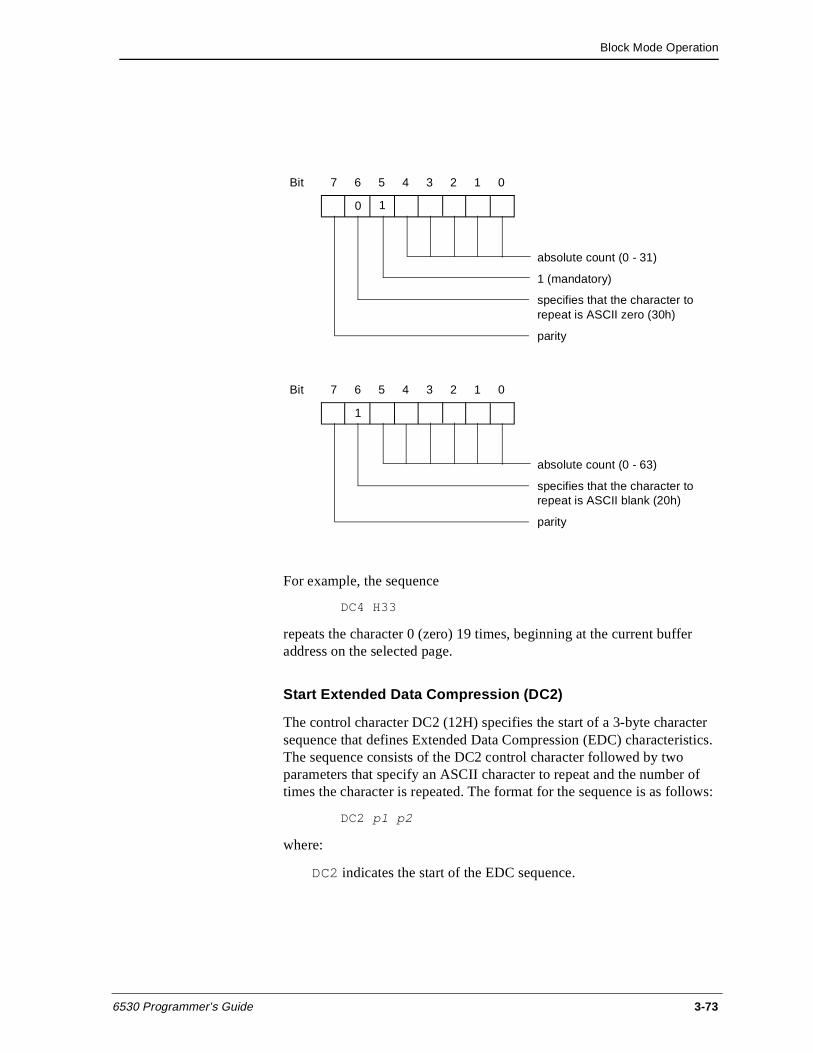
Block Mode Operation
6530 Programmer’s Guide 3-73
For example, the sequence
DC4 H33
repeats the character 0 (zero) 19 times, beginning at the current buffer address on the selected page.
Start Extended Data Compression (DC2)
The control character DC2 (12H) specifies the start of a 3-byte character sequence that defines Extended Data Compression (EDC) characteristics. The sequence consists of the DC2 control character followed by two parameters that specify an ASCII character to repeat and the number of times the character is repeated. The format for the sequence is as follows:
DC2 p1 p2
where:
DC2 indicates the start of the EDC sequence.
Bit 7 6 5 4 3 2 1 0
absolute count (0 - 31)
1 (mandatory)
specifies that the character to repeat is ASCII zero (30h)
parity
0 1
Bit 7 6 5 4 3 2 1 0
absolute count (0 - 63)
specifies that the character to repeat is ASCII blank (20h)
parity
1
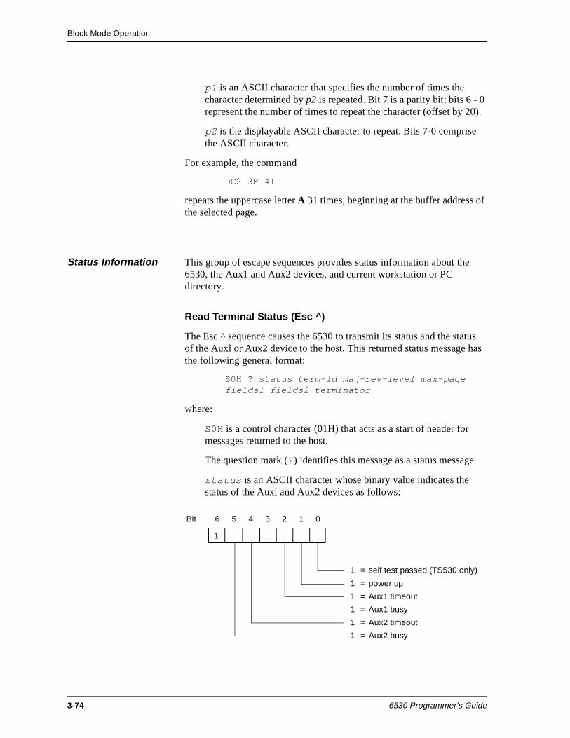
Block Mode Operation
3-74 6530 Programmer’s Guide
p1 is an ASCII character that specifies the number of times the character determined by p2 is repeated. Bit 7 is a parity bit; bits 6 - 0 represent the number of times to repeat the character (offset by 20).
p2 is the displayable ASCII character to repeat. Bits 7-0 comprise the ASCII character.
For example, the command
DC2 3F 41
repeats the uppercase letter A 31 times, beginning at the buffer address of the selected page.
Status Information This group of escape sequences provides status information about the 6530, the Aux1 and Aux2 devices, and current workstation or PC directory.
Read Terminal Status (Esc ^)
The Esc ^ sequence causes the 6530 to transmit its status and the status of the Auxl or Aux2 device to the host. This returned status message has the following general format:
S0H ? status term-id maj-rev-level max-page fields1 fields2 terminator
where:
S0H is a control character (01H) that acts as a start of header for messages returned to the host.
The question mark (?) identifies this message as a status message.
status is an ASCII character whose binary value indicates the status of the Auxl and Aux2 devices as follows:
Bit 6 5 4 3 2 1 0
1 = self test passed (TS530 only)
1 = power up
1 = Aux1 timeout
1 = Aux1 busy
1 = Aux2 timeout
1 = Aux2 busy
1
Block Mode Operation
6530 Programmer’s Guide 3-75
Bit 0 is always set to 1 for compatibility with the 653x. Bit 1 is set the first time this escape sequence is issued after a power up. Bits 2 and 4 are set or cleared based on the last output operation to the respective devices. Bits 3 and 5 are set only when the respective ports are busy outputting data.
term-id is an ASCII character that identifies the terminal type. For the 6530, this is always F.
maj-rev-level is an ASCII character that identifies the major revision level of the 6530 (for example B for B30 or B40).
max-page is an ASCII character whose code specifies the maximum number of pages available (as defined by default or the Esc p sequence).
fields1 and fields2 are encoded ASCII characters whose six least significant bits comprise a 12-bit integer. This integer represents the average number of fields that can be defined for each page. For example, if the ASCII characters X and Y are returned in fields1 and fields2, respectively, they represent an average of 1561 fields that can be defined per page. The maximum value returned is 4096. If room is available for more than this number of fields, 4096 is returned. The value returned is only valid in protect submode.
terminator comprises the control characters ETX (03H) and LRC (Longitudinal Redundancy Check) in block mode.
Read Full Revision Level (Esc _)
The Esc _ sequence causes the 6530 to transmit its full revision level to the host. The returned message has the following general format
S0H # rev-level TO device-rev-level terminator
where:
SOH is a control character (01H) that acts as a start of header for messages returned to the host.
The number sign (#) identifies this message as a firmware message.
rev-level consists of three ASCII characters that identify the 6530’s revision level (for example, B42).
TO and device-rev-level are returned for compatibility with 6530 options. device-rev-level is always the same as rev-level.
terminator comprises the control characters ETX (03H) and LRC (Longitudinal Redundancy Check) in block mode.
Block Mode Operation
3-76 6530 Programmer’s Guide
Get Machine Name (Esc - e)
The Esc - e sequence is valid only for a workstation or PC that is running under MS-DOS on a Multilan connection. The escape sequence causes the 6530 to transmit the machine (LAN) name currently set for the workstation or PC. The returned message has the following format:
SOH & string terminator
where:
SOH is a control character (OlH) that acts as a start of header for messages returned to the host.
The ampersand (&) identifies this message as a machine name message.
string is the ASCII character string value for the machine name setting. If no characters are returned, the machine name has not been set at the workstation or PC.
terminator comprises the control characters ETX (03H) and LRC (Longitudinal Redundancy Check) in block mode.
Get Current Directory and Redirection Information (Esc - f)
The Esc - f sequence causes the 6530 to transmit the pathname of the current directory for a specified drive of the workstation or PC. The escape sequence is valid only for a workstation or PC that is running under MS-DOS on a Multilan connection. If the workstation or PC is on a Multilan connection and the specified drive is on the network redirection list, the 6530 also returns the redirection list entry for the drive. The escape sequence has the following format:
Esc - f drive
where:
drive is an ASCII character in the range of @ (40H) through Z (5AH) that specifies the current workstation or PC drive.
The returned message has the following format;
S0H ’ drive DC2 string1 DC2 string2 terminator
where:
S0H is a control character (01H) that acts as a start of header for messages returned to the host.
The apostrophe ( ’ ) identifies this message as a directory and redirection message.
Block Mode Operation
6530 Programmer’s Guide 3-77
drive is an ASCII character in the range of 41H through 5AH that specifies the current default drive of the workstation or PC.
DC2 is a control character (12H) used to delimit the following string values.
string1 is an ASCII string of 1 or more characters that represents the full pathname (starting from the root and including the backslash) of the current directory for the specified drive. If the length of string1 is 0, the 6530 received an operating system error when retrieving the information.
string2 is an ASCII string of 1 or more characters that represents the network redirection entry for the specified drive. If the length of string2 is 0, either the 6530 received an operating system error when retrieving the information or the specified drive is not in the network redirection table.
terminator comprises the control characters ETX (03H) and LRC (Longitudinal Redundancy Check) in block mode.
Device Control This group of escape sequences performs operations on devices attached to the workstation or PC. See “Device Control” on page 1-11, for general information about device control.
Print Page (Esc 0)
The Esc 0 sequence transfers the contents of the currently selected page to the workstation or PC device specified by the Auxl parameter. The 6530 reserves a one-page print buffer to save the data to be printed. When the print function is invoked, the selected page is moved into the print buffer. because this is saved in a separate area of memory, the keyboard need not be locked while the data is printing even if the currently selected page is also the currently displayed page.
Print requests from your application always take precedence over local requests by the user. If your application requests a print operation while one is in process, the 6530 performs the following:
n Aborts the current print operation; displays an error message (PRINT ABORT) in the error line and sounds the bell
n Sends a carriage return (CR), followed by a form feed (FF), to the printer interface
n Initiates the application’s print request
Block Mode Operation
3-78 6530 Programmer’s Guide
This abort can be avoided if your application observes the following sequence:
1. Lock the keyboard (Esc c sequence).
2. Check the status for a print in process (Esc ^ sequence).
3. If no print is in process, send the new print request (Esc 0 sequence).
4. Unlock the keyboard (Esc b sequence).
A program reset, system reset, or mode switch will also abort a print operation in process.
If the user requests a print operation while one is in process, this second print request is ignored. Also, the error message PRINT BUSY is displayed in the error line and the bell is sounded.
If a video attribute is encountered while transmitting text to the Auxl device, a space character (20H) is substituted in the print stream for the attribute character. If the video attribute includes invisible, space characters. (20H) are substituted in the print stream for subsequent text. If the video attribute includes underscore and the Aux1 line end parameter is not set to CR, subsequent text sent to the printer is followed by a CR (ODH) and a line with underscore characters (_,5FH) for each character position that is to be underscored. When the Auxl line end parameter is set to CR, the underscore attribute is ignored.
Write to Auxl or Aux2 Device (Esc - 0)
The Esc - O sequence outputs host-generated data to the workstation or PC device specified by either the Auxl or Aux2 parameter. All text following the escape sequence is written verbatim to the selected device. The text sequence can include any character code that is passable by conversational mode and the communications protocol used. The text sequence is normally terminated by a DC2 control character (l2H). You can specify a different terminating character if necessary.
The Esc - 0 sequence has the following general format:
Esc - device ; terminator 0
where:
device is a decimal number that specifies which device parameter is used. This must be either 1 for the Auxl device or 2 for the Aux2 device. If any other value is specified or the parameter is omitted, the 6530 assumes the Auxl device.
Block Mode Operation
6530 Programmer’s Guide 3-79
terminator is a decimal number in the range of 3 through 127 that specifies a terminating character you have chosen to represent the end-of-text sequence. The number represents the decimal value of the ASCII character code. For example, the number 19 specifies a DC3 control character (l3H). If this parameter is omitted, a DC2 control character (12H) is assumed.
Note Make sure the data passed to the device is terminated properly. Otherwise, all data from your application, including control codes and escape sequences will continue to be passed to the device and will not be processed by the 6530.
Write to File or Device Name (Esc { )
The Esc { sequence allows your application to open, write to, and then close an operating system file or device name. (Note that you cannot check the status of the operation performed with this escape sequence. Thus, it recommended that you use the Esc } sequence to perform both write and read operations on a device.) The format of the escape sequence is as follows:
Esc { “ device” opcode SPACE data CR
where:
device is the operating system file or device name. Note that the device name must be enclosed in quotes.
opcode is one of the following ASCII hexadecimal pairs that specifies the operation to be performed (these correspond to the same codes used to make operating system calls):
SPACE represents a space (hex value H20), which must precede the data.
3C = create 40 = write
3D = open 43 = seek EOF
3E = close 42 = delete
3F = read
Block Mode Operation
3-80 6530 Programmer’s Guide
data is the data to be written to the device when a write (40) operation is specified. A space must precede the data. The data can be:
A mode switch sequence that specifies the type of data (Esc a for ASCII data or Esc b for binary data) to be sent on a subsequent write
ASCII characters in the range of 20H to 7E
Binary data specified by pairs of ASCII hexadecimal pairs that represent
single characters in the range of 00H to FFH
CR is a control character (0DH) that terminates the escape sequence.
See the programmer’s guide for your workstation’s operating system for more information about writing to a file or device.
Write/Read to File or Device Name (Esc } )
The Esc } sequence allows your application to perform I/O operations on an operating system file or device name. The format of the escape sequence is as follows:
Esc } “ device” operation SPACE data CR
where:
device is the operating system file or device name to which you are performing the write/read operation. Note that the device name must be enclosed in quotes.
operation is one of the following ASCII hexadecimal pairs that specifies the function to be performed (these correspond to the same codes used to make operating system calls):
The write/read operation is a composite of an operating system write function followed by a read. The read status information, however, is returned in the message described below.
3C = create 40 = write
3D = open 42 = delete
3E = close 43 = seek EOF
3F = read
Block Mode Operation
6530 Programmer’s Guide 3-81
SPACE represents a space (hex value H20), which must precede the data.
data is the data to be written to the device when a write (40) operation is specified. A space must precede the data. The data can be:
A mode switch sequence that specifies the type of data (Esc a for ASCII data or Esc b for binary data) to be sent on a subsequent write
ASCII characters in the range of 20H to 7E
Binary data specified by pairs of ASCII hexadecimal pairs that represent single characters in the range of 00H to FFH
CR is a control character (0DH) that terminates the escape sequence.
On all operations, except for reads, the escape sequence returns a message with the following format:
SOH % status data terminator
where:
SOH is a control character (01H) that acts as a start of header for messages returned to the host.
The percent sign (%) identifies this message as an operating system read message.
status is one of the following ASCII characters that indicates the status of the operation:
space (20H) = operation successful
(22H) = file not found
$ (24H) = too many files open
% (25H) = access denied
& (26H) = invalid handle
, (2CH) = invalid access
{ (7BH) = invalid opcode
| (7CH) = invalid device
} (7DH) = device not open
~ (7EH) = invalid format #,
Block Mode Operation
3-82 6530 Programmer’s Guide
data is the data read from the device when a read operation is specified. 0nly 255 bytes of text data can be returned at one time. To perform sequential read operations, your application should continue issuing the Esc } sequence until 0 bytes are returned in data.
terminator comprises the control characters ETX (03H) and LRC (Longitudinal Redundancy Check) in block mode.
See the programmer’s guide for your operating system for more information on performing I/O on a device driver.
Load and Execute an Operating System Program (Esc - V)
The Esc - V sequence allows your application to start an MS-DOS program from the 6530. The user must set the EXEC function parameter to ON to allow this escape sequence. The escape sequence has the following format:
Esc - V filename [parameters] - terminator
where:
filename is the file name of the operating system program to be started. Only the file name (with the .exe or .com extension) should be specified - not the path. This means the user must have the path set correctly for the program file.
parameters specify the command line parameters (if any) required by the program to be started.
This escape sequence is equivalent to the operating system execute process function. Refer to the programmer’s guide for your operating system for more information.
Note The Esc - V sequence causes the 6530 to suspend communications with the host system until the process has completed.
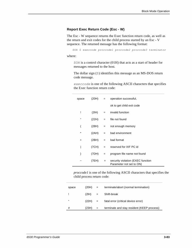
Block Mode Operation
6530 Programmer’s Guide 3-83
Report Exec Return Code (Esc - W)
The Esc - W sequence returns the Exec function return code, as well as the return and exit codes for the child process started by an Esc - V sequence. The returned message has the following format:
SOH $ execcode proccodel proccode2 proccode3 terminator
where:
SOH is a control character (01H) that acts as a start of header for messages returned to the host.
The dollar sign ($) identifies this message as an MS-DOS return code message.
execcode is one of the following ASCII characters that specifies the Exec function return code:
proccode1 is one of the following ASCII characters that specifies the child process return code:
space (20H) = operation successful,
ok to get child exit code
! (2lH) = invalid function
“ (22H) = file not found
( (28H) = not enough memory
* (2AH) = bad environment
+ (2BH) = bad format
| (7CH) = reserved for IXF PC id
} (7DH) = program file name not found
~ (7EH) = security violation (EXEC function Parameter not set to ON)
space (20H) = terminate/abort (normal termination)
! (2lH) = Shift-break
“ (22H) = fatal error (critical device error)
# (23H) = terminate and stay resident (KEEP process)
Block Mode Operation
3-84 6530 Programmer’s Guide
proccode2 and proccode3 are ASCII characters in the range of 20H to 2FH whose ASCII codes offset by 1FH represent the nibble values for the child process exit code. The most significant nibble is represented by proccode2, and the least significant nibble is represented by proccode3.
terminator comprises the control characters ETX (03H) and LRC (Longitudinal Redundancy Check) in block mode.
See the programmer’s guide for your operating system for more information.
Disconnect Modem (Esc f)
The Esc f sequence forces the Data Terminal Ready line (CD) into a low state for three seconds. This causes most modems to disconnect and to terminate the connection.
General Operations This group of control codes and escape sequences performs a variety of terminal functions.
Bell (BEL)
The BEL control character (07H) causes the 6530 to sound an audible alarm. It is typically used to alert the user of some action, such as an error.
Define Field Attribute (FS)
The FS (1CH) character indicates the start of a 4-character sequence that assigns a set of attributes by allowing an application to select an element from either the Fixed Field Definitions table or the Variable Field Definitions table. (SeeTable 3-9, “Fixed Field Definitions Table - Assigned by EM3270,” on page 86 and Table 3-10, “Variable Field Definitions Table - Default Values,” on page 89.) The format of the sequence is as follows:
FS p1 p2 p3
where:
FS starts the sequence.
p1 specifies the screen row number, from 1 - 24 (20h - 37h), at which the redefined video attributes begin. The format is the same as that of the Set Buffer Address sequence (DC1).
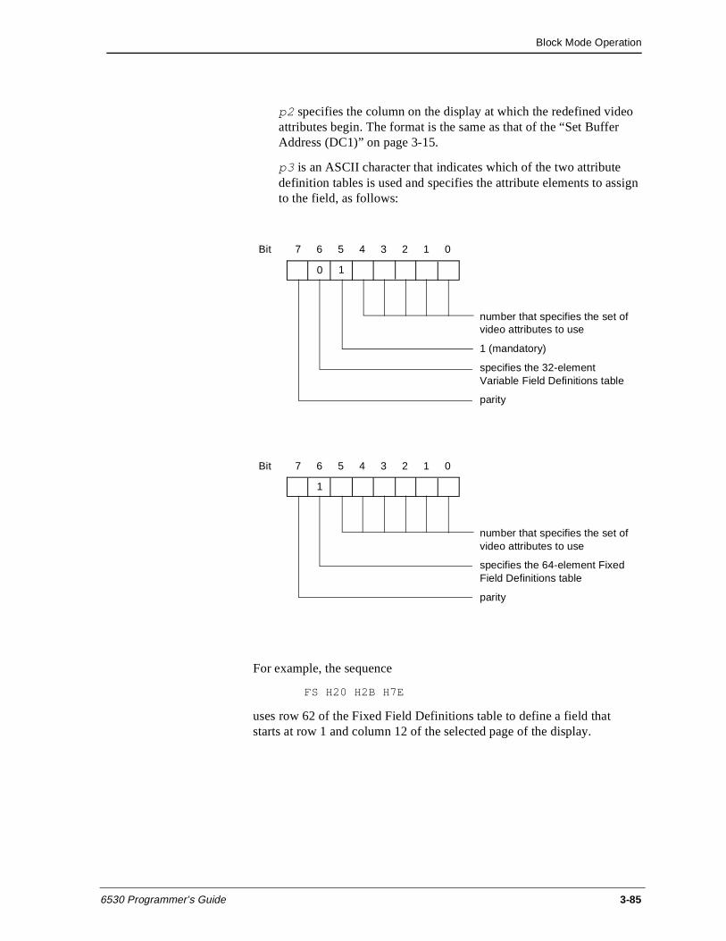
Block Mode Operation
6530 Programmer’s Guide 3-85
p2 specifies the column on the display at which the redefined video attributes begin. The format is the same as that of the “Set Buffer Address (DC1)” on page 3-15.
p3 is an ASCII character that indicates which of the two attribute definition tables is used and specifies the attribute elements to assign to the field, as follows:
For example, the sequence
FS H20 H2B H7E
uses row 62 of the Fixed Field Definitions table to define a field that starts at row 1 and column 12 of the selected page of the display.
Bit 7 6 5 4 3 2 1 0
number that specifies the set of video attributes to use
1 (mandatory)
specifies the 32-element Variable Field Definitions table
parity
0 1
Bit 7 6 5 4 3 2 1 0
number that specifies the set of video attributes to use
specifies the 64-element Fixed Field Definitions table
parity
1
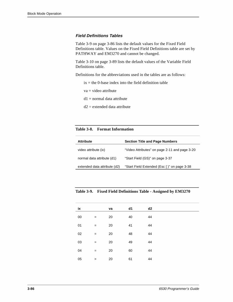
Block Mode Operation
3-86 6530 Programmer’s Guide
Field Definitions Tables
Table 3-9 on page 3-86 lists the default values for the Fixed Field Definitions table. Values on the Fixed Field Definitions table are set by PATHWAY and EM3270 and cannot be changed.
Table 3-10 on page 3-89 lists the default values of the Variable Field Definitions table.
Definitions for the abbreviations used in the tables are as follows:
ix = the 0-base index into the field definition table
va = video attribute
d1 = normal data attribute
d2 = extended data attribute
Table 3-8. Format Information
Attribute Section Title and Page Numbers
video attribute (ix) “Video Attributes” on page 2-11 and page 3-20
normal data attribute (d1) “Start Field (GS)” on page 3-37
extended data attribute (d2) “Start Field Extended (Esc [ )” on page 3-38
Table 3-9. Fixed Field Definitions Table - Assigned by EM3270
ix va d1 d2
00 = 20 40 44
01 = 20 41 44
02 = 20 48 44
03 = 20 49 44
04 = 20 60 44
05 = 20 61 44
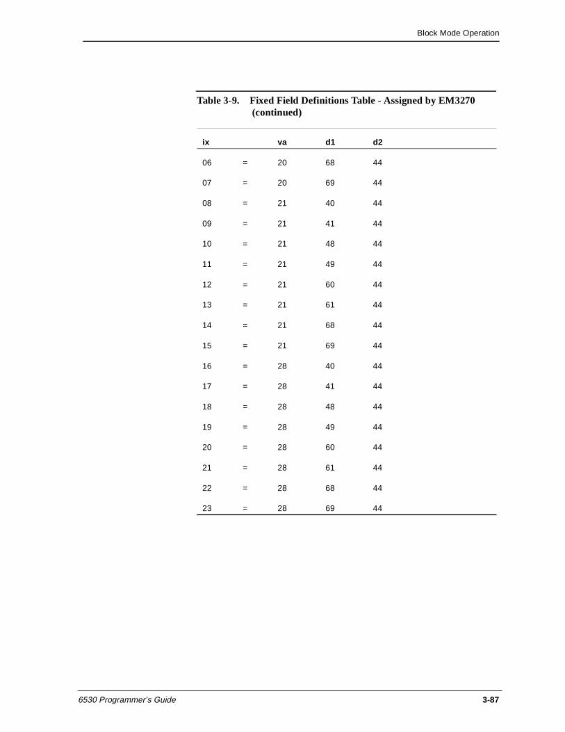
Block Mode Operation
6530 Programmer’s Guide 3-87
06 = 20 68 44
07 = 20 69 44
08 = 21 40 44
09 = 21 41 44
10 = 21 48 44
11 = 21 49 44
12 = 21 60 44
13 = 21 61 44
14 = 21 68 44
15 = 21 69 44
16 = 28 40 44
17 = 28 41 44
18 = 28 48 44
19 = 28 49 44
20 = 28 60 44
21 = 28 61 44
22 = 28 68 44
23 = 28 69 44
Table 3-9. Fixed Field Definitions Table - Assigned by EM3270 (continued)
ix va d1 d2

Block Mode Operation
3-88 6530 Programmer’s Guide
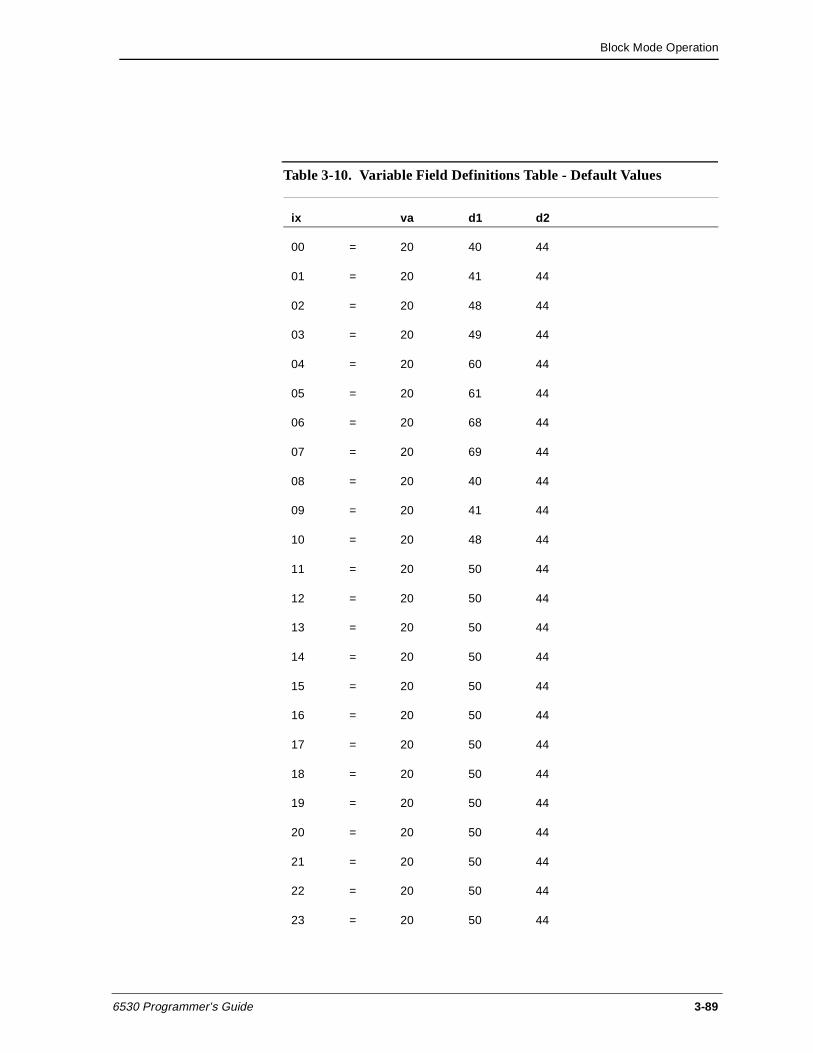
Block Mode Operation
6530 Programmer’s Guide 3-89
Table 3-10. Variable Field Definitions Table - Default Values
ix va d1 d2
00 = 20 40 44
01 = 20 41 44
02 = 20 48 44
03 = 20 49 44
04 = 20 60 44
05 = 20 61 44
06 = 20 68 44
07 = 20 69 44
08 = 20 40 44
09 = 20 41 44
10 = 20 48 44
11 = 20 50 44
12 = 20 50 44
13 = 20 50 44
14 = 20 50 44
15 = 20 50 44
16 = 20 50 44
17 = 20 50 44
18 = 20 50 44
19 = 20 50 44
20 = 20 50 44
21 = 20 50 44
22 = 20 50 44
23 = 20 50 44
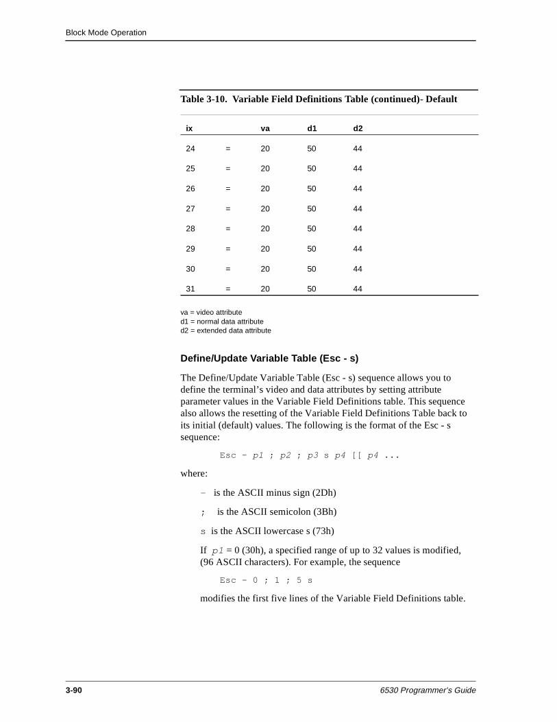
Block Mode Operation
3-90 6530 Programmer’s Guide
va = video attributed1 = normal data attributed2 = extended data attribute
Define/Update Variable Table (Esc - s)
The Define/Update Variable Table (Esc - s) sequence allows you to define the terminal’s video and data attributes by setting attribute parameter values in the Variable Field Definitions table. This sequence also allows the resetting of the Variable Field Definitions Table back to its initial (default) values. The following is the format of the Esc - s sequence:
Esc - p1 ; p2 ; p3 s p4 [[ p4 ...
where:
- is the ASCII minus sign (2Dh)
; is the ASCII semicolon (3Bh)
s is the ASCII lowercase s (73h)
If p1 = 0 (30h), a specified range of up to 32 values is modified, (96 ASCII characters). For example, the sequence
Esc - 0 ; 1 ; 5 s
modifies the first five lines of the Variable Field Definitions table.
24 = 20 50 44
25 = 20 50 44
26 = 20 50 44
27 = 20 50 44
28 = 20 50 44
29 = 20 50 44
30 = 20 50 44
31 = 20 50 44
Table 3-10. Variable Field Definitions Table (continued)- Default
ix va d1 d2
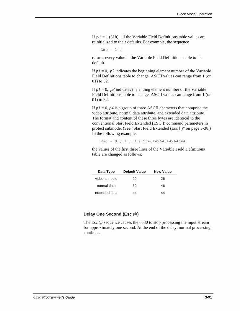
Block Mode Operation
6530 Programmer’s Guide 3-91
If p1 = 1 (31h), all the Variable Field Definitions table values are reinitialized to their defaults. For example, the sequence
Esc - 1 s
returns every value in the Variable Field Definitions table to its default.
If p1 = 0, p2 indicates the beginning element number of the Variable Field Definitions table to change. ASCII values can range from 1 (or 01) to 32.
If p1 = 0, p3 indicates the ending element number of the Variable Field Definitions table to change. ASCII values can range from 1 (or 01) to 32.
If p1 = 0, p4 is a group of three ASCII characters that comprise the video attribute, normal data attribute, and extended data attribute. The format and content of these three bytes are identical to the conventional Start Field Extended (ESC ]) command parameters in protect submode. (See “Start Field Extended (Esc [ )” on page 3-38.) In the following example:
Esc - 0 ; 1 ; 3 s 264644264644264644
the values of the first three lines of the Variable Field Definitions table are changed as follows:
Delay One Second (Esc @)
The Esc @ sequence causes the 6530 to stop processing the input stream for approximately one second. At the end of the delay, normal processing continues.
Data Type Default Value New Value
video attribute 20 26
normal data 50 46
extended data 44 44
Block Mode Operation
3-92 6530 Programmer’s Guide
Disable Local Line Editing (Esc N)
The Esc N sequence disables the insert line and delete line operations on the keyboard (Ctrl-Ins and Ctrl-Del keys) and redefines these keys as additional function keys. These function key definitions are in effect until one of the following occurs:
n A reinitialize (Esc q) sequence is issued.
n Block mode is exited and reentered.
n A transition is made from protect to nonprotect submode.
The Esc N sequence is only effective in nonprotect submode because local line editing is automatically disabled in protect submode.
Unlock Keyboard (Esc b)
The Esc b sequence unlocks the keyboard and erases the KBD LOCKED phrase in the status line.
Lock Keyboard (Esc c)
The Esc c sequence locks the keyboard and displays the phrase KBD LOCKED in the status line. When the keyboard is locked, the cursor is no longer displayed and all keys (except Caps Lock, Num Lock, Ctrl-Scroll Lock, Ctrl-End, Ctrl-Alt-Del, Ctrl-Backspace, and Alt-Backspace) are disabled.
Simulate Function Key (Esc d)
The Esc d sequence simulates the depression of a function key. After receiving an Esc d sequence, the 6530 locks the keyboard and, on the next read, transmits a function key message to the host. The Esc d is followed by a single character that designates the keycode for the simulated function key. For example, if your application sends an Esc d X sequence, the 6530 generates the following message:
SOH X page cursor
where:
SOH is a control character (01H) that acts as a start of header for messages returned to the host.
X is an ASCII character that identifies which function key was pressed. Function keys are listed in Table 3-11 on page 3-95.
page is an ASCII character whose code, offset by 20H, specifies the page number of the current displayed page.
Block Mode Operation
6530 Programmer’s Guide 3-93
cursor specifies the row and column for the current cursor position. This will have either the normal or the extended addressing format as described in “Cursor and Buffer Addressing” on page 3-13.
Write to Message Field (Esc o)
The Esc o sequence allows your application program to write text into the message field of the message/status line. (See Chapter 1 for a discussion of the message/status line format). The Esc o code is followed by the text to be displayed, and the sequence is terminated by a CR control character (ODH). For example, the following sequence writes the phrase SELECT OPTION in the message field:
Esc o SELECT OPTION CR
The 6530 clears an existing message before writing the new text. Thus, to simply clear the message field. you can send:
Esc o CR
The message can also be assigned video attributes by embedding Esc 6 sequences within the text.
Reinitialize (Esc q)
The Esc q sequence executes an initialization sequence similar to that executed upon entering block mode. The exceptions to this are as follows:
n Page 1 is blank filled (rather than containing the screen text from conversational mode).
n The communications line is not reinitialized.
Terminate Remote 6530 Operation (Esc - z)
The Esc - z sequence allows you to control the 6530’s remote termination, and allows you to pass error-level information up to the MS-DOS system. This makes it possible to execute programs from batch files that are too large to “spawn off” and keep the 6530 resident. On receipt of this escape sequence, the 6530 terminates execution through the same logic as if the user had pressed the Ctrl-End key sequence. The parameter p is an ASCII decimal value to be passed up as the exit error-level. This can be checked in MS-DOS batch files to control execution of that batch file. The format for the sequence is as follows:
Block Mode Operation
3-94 6530 Programmer’s Guide
Esc - p1 z
1B 2D p 7A (hex values)
where:
p1 is the exit error-level (an ASCII decimal value).
Execute Self Test (Esc z)
This command sequence is used at the factory to run self-tests on terminals (not terminal emulators).
Shift Out to G1 Character Set (S0)
The S0 control character (0EH) shifts the 6530 to the G1 character set. Thus, graphics characters in the G1 set are displayed on the screen. (The G1 set is the same as the alternate character set supported on the workstation or PC.)
The S0 character is interpreted independently of the current state of any escape sequence. Only graphics characters sent to the display are affected. Control characters within any escape sequence are not shifted.
Shift In to G0 Character Set (S1)
The S1 control character (0FH) shifts the 6530 to the standard G0 character set.
Function Keys The user can request an application-defined function by pressing one of the function keys. In block mode, a number of keys are interpreted as function keys.These include:
n Fl-F16 (unshifted and shifted). On workstation or PC keyboards with only 10 function keys, the 6530 maps Fl1 through Fl6 to Alt-F1 through Alt-F6, respectively. On workstation or PC keyboards with only 12 function keys, the 6530 maps F13 through F16 to Alt-F3 through Alt-F6, respectively.
n Alt-up arrow and Alt-down arrow (unshifted and shifted)
n Pg Up, Pg Dn, Alt-Pg Up, Alt-Pg Dn
n Ctrl-Ins, Ctrl-Del (if the local function is disabled by the Esc N sequence; in protect submode, these are automatically defined as function keys.)
n Enter (if the return function Configuration parameter is enabled)
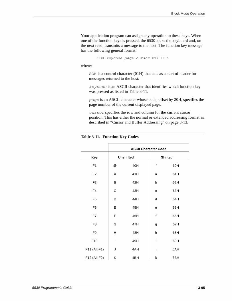
Block Mode Operation
6530 Programmer’s Guide 3-95
Your application program can assign any operation to these keys. When one of the function keys is pressed, the 6530 locks the keyboard and, on the next read, transmits a message to the host. The function key message has the following general format:
SOH keycode page cursor ETX LRC
where:
SOH is a control character (01H) that acts as a start of header for messages returned to the host.
keycode is an ASCII character that identifies which function key was pressed as listed in Table 3-11.
page is an ASCII character whose code, offset by 20H, specifies the page number of the current displayed page.
cursor specifies the row and column for the current cursor position. This has either the normal or extended addressing format as described in “Cursor and Buffer Addressing” on page 3-13.
Table 3-11. Function Key Codes
ASCII Character Code
Key Unshifted Shifted
F1 @ 40H ‘ 60H
F2 A 41H a 61H
F3 B 42H b 62H
F4 C 43H c 63H
F5 D 44H d 64H
F6 E 45H e 65H
F7 F 46H f 66H
F8 G 47H g 67H
F9 H 48H h 68H
F10 I 49H i 69H
F11 (Alt-F1) J 4AH j 6AH
F12 (Alt-F2) K 4BH k 6BH
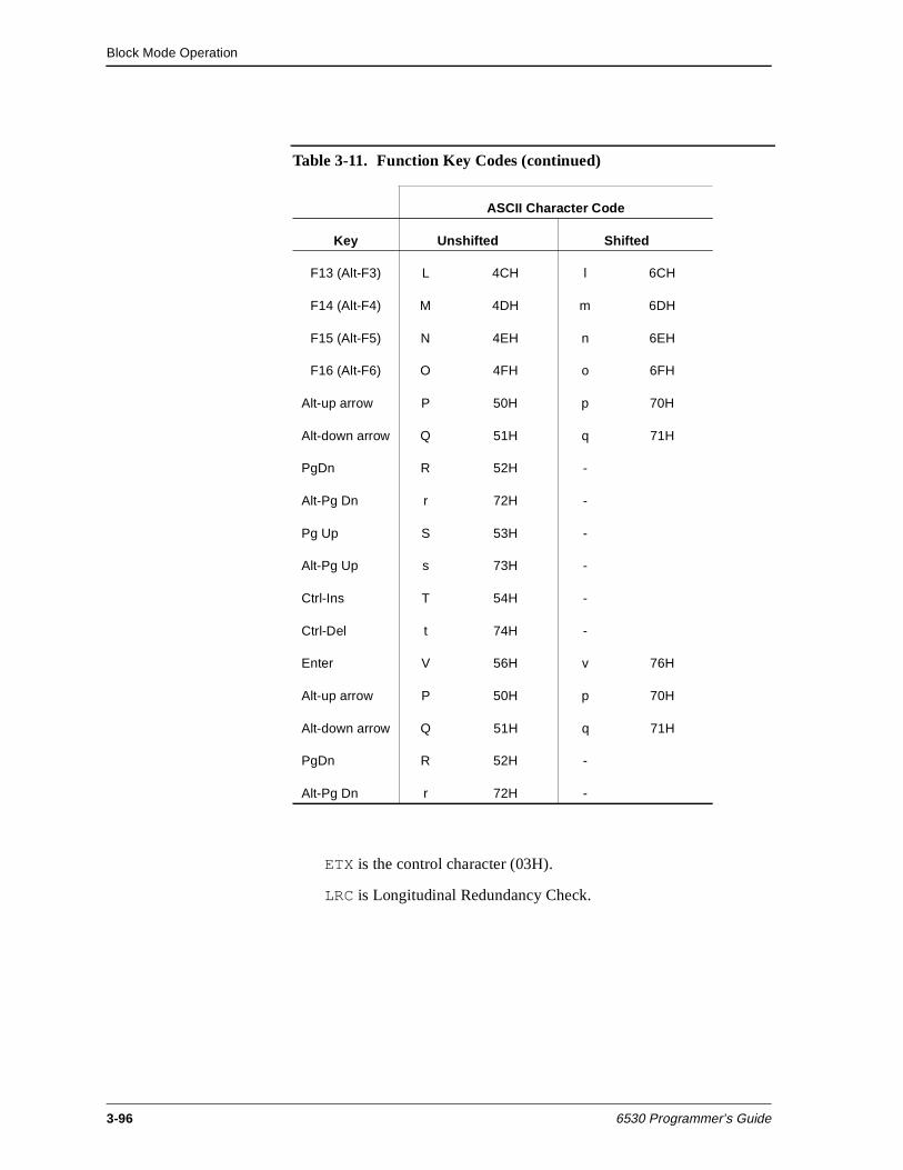
Block Mode Operation
3-96 6530 Programmer’s Guide
ETX is the control character (03H).
LRC is Longitudinal Redundancy Check.
F13 (Alt-F3) L 4CH l 6CH
F14 (Alt-F4) M 4DH m 6DH
F15 (Alt-F5) N 4EH n 6EH
F16 (Alt-F6) O 4FH o 6FH
Alt-up arrow P 50H p 70H
Alt-down arrow Q 51H q 71H
PgDn R 52H -
Alt-Pg Dn r 72H -
Pg Up S 53H -
Alt-Pg Up s 73H -
Ctrl-Ins T 54H -
Ctrl-Del t 74H -
Enter V 56H v 76H
Alt-up arrow P 50H p 70H
Alt-down arrow Q 51H q 71H
PgDn R 52H -
Alt-Pg Dn r 72H -
Table 3-11. Function Key Codes (continued)
ASCII Character Code
Key Unshifted Shifted
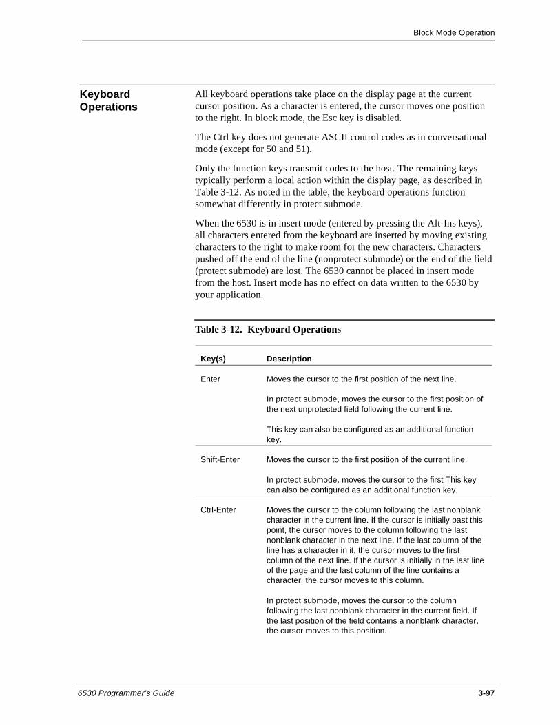
Block Mode Operation
6530 Programmer’s Guide 3-97
Keyboard Operations
All keyboard operations take place on the display page at the current cursor position. As a character is entered, the cursor moves one position to the right. In block mode, the Esc key is disabled.
The Ctrl key does not generate ASCII control codes as in conversational mode (except for 50 and 51).
Only the function keys transmit codes to the host. The remaining keys typically perform a local action within the display page, as described in Table 3-12. As noted in the table, the keyboard operations function somewhat differently in protect submode.
When the 6530 is in insert mode (entered by pressing the Alt-Ins keys), all characters entered from the keyboard are inserted by moving existing characters to the right to make room for the new characters. Characters pushed off the end of the line (nonprotect submode) or the end of the field (protect submode) are lost. The 6530 cannot be placed in insert mode from the host. Insert mode has no effect on data written to the 6530 by your application.
Table 3-12. Keyboard Operations
Key(s) Description
Enter Moves the cursor to the first position of the next line.
In protect submode, moves the cursor to the first position of the next unprotected field following the current line.
This key can also be configured as an additional function key.
Shift-Enter Moves the cursor to the first position of the current line.
In protect submode, moves the cursor to the first This key can also be configured as an additional function key.
Ctrl-Enter Moves the cursor to the column following the last nonblank character in the current line. If the cursor is initially past this point, the cursor moves to the column following the last nonblank character in the next line. If the last column of the line has a character in it, the cursor moves to the first column of the next line. If the cursor is initially in the last line of the page and the last column of the line contains a character, the cursor moves to this column.
In protect submode, moves the cursor to the column following the last nonblank character in the current field. If the last position of the field contains a nonblank character, the cursor moves to this position.
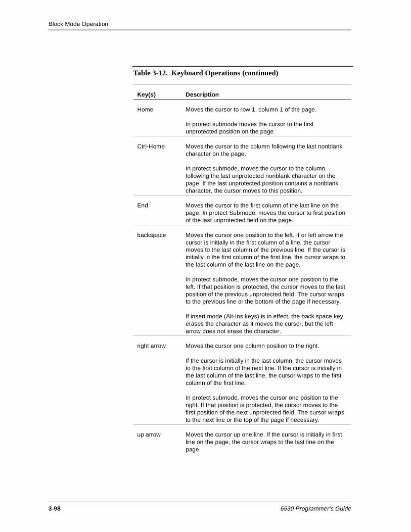
Block Mode Operation
3-98 6530 Programmer’s Guide
Home Moves the cursor to row 1, column 1 of the page.
In protect submode moves the cursor to the first unprotected position on the page.
Ctrl-Home Moves the cursor to the column following the last nonblank character on the page.
In protect submode, moves the cursor to the column following the last unprotected nonblank character on the page. If the last unprotected position contains a nonblank character, the cursor moves to this position.
End Moves the cursor to the first column of the last line on the page. In protect Submode, moves the cursor to first position of the last unprotected field on the page.
backspace Moves the cursor one position to the left. If or left arrow the cursor is initially in the first column of a line, the cursor moves to the last column of the previous line. If the cursor is initially in the first column of the first line, the cursor wraps to the last column of the last line on the page.
In protect submode, moves the cursor one position to the left. If that position is protected, the cursor moves to the last position of the previous unprotected field. The cursor wraps to the previous line or the bottom of the page if necessary.
If insert mode (Alt-Ins keys) is in effect, the back space key erases the character as it moves the cursor, but the left arrow does not erase the character.
right arrow Moves the cursor one column position to the right.
If the cursor is initially in the last column, the cursor moves to the first column of the next line. If the cursor is initially in the last column of the last line, the cursor wraps to the first column of the first line.
In protect submode, moves the cursor one position to the right. If that position is protected, the cursor moves to the first position of the next unprotected field. The cursor wraps to the next line or the top of the page if necessary.
up arrow Moves the cursor up one line. If the cursor is initially in first line on the page, the cursor wraps to the last line on the page.
Table 3-12. Keyboard Operations (continued)
Key(s) Description
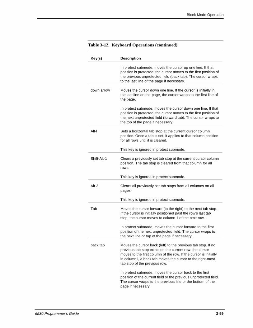
Block Mode Operation
6530 Programmer’s Guide 3-99
In protect submode, moves the cursor up one line. If that position is protected, the cursor moves to the first position of the previous unprotected field (back tab). The cursor wraps to the last line of the page if necessary.
down arrow Moves the cursor down one line. If the cursor is initially in the last line on the page, the cursor wraps to the first line of the page.
In protect submode, moves the cursor down one line. If that position is protected, the cursor moves to the first position of the next unprotected field (forward tab). The cursor wraps to the top of the page if necessary.
Alt-l Sets a horizontal tab stop at the current cursor column position. Once a tab is set, it applies to that column position for all rows until it is cleared.
This key is ignored in protect submode.
Shift-Alt-1 Clears a previously set tab stop at the current cursor column position. The tab stop is cleared from that column for all rows.
This key is ignored in protect submode.
Alt-3 Clears all previously set tab stops from all columns on all pages.
This key is ignored in protect submode.
Tab Moves the cursor forward (to the right) to the next tab stop. If the cursor is initially positioned past the row’s last tab stop, the cursor moves to column 1 of the next row.
In protect submode, moves the cursor forward to the first position of the next unprotected field. The cursor wraps to the next line or top of the page if necessary.
back tab Moves the cursor back (left) to the previous tab stop. If no previous tab stop exists on the current row, the cursor moves to the first column of the row. If the cursor is initially in column l, a back tab moves the cursor to the right-most tab stop of the previous row.
In protect submode, moves the cursor back to the first position of the current field or the previous unprotected field. The cursor wraps to the previous line or the bottom of the page if necessary.
Table 3-12. Keyboard Operations (continued)
Key(s) Description
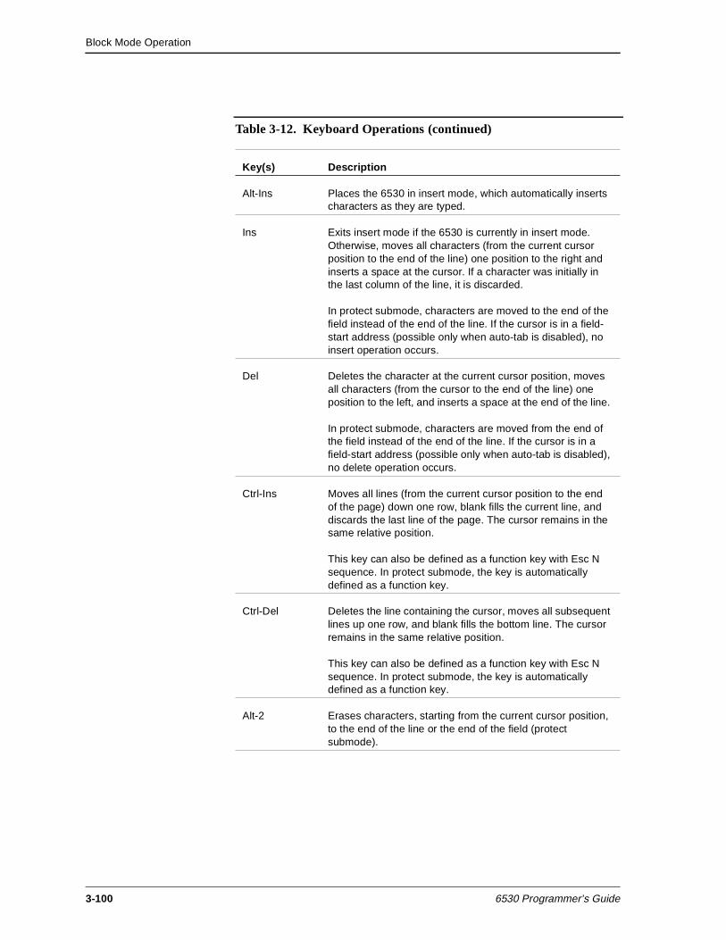
Block Mode Operation
3-100 6530 Programmer’s Guide
Alt-Ins Places the 6530 in insert mode, which automatically inserts characters as they are typed.
Ins Exits insert mode if the 6530 is currently in insert mode. Otherwise, moves all characters (from the current cursor position to the end of the line) one position to the right and inserts a space at the cursor. If a character was initially in the last column of the line, it is discarded.
In protect submode, characters are moved to the end of the field instead of the end of the line. If the cursor is in a field-start address (possible only when auto-tab is disabled), no insert operation occurs.
Del Deletes the character at the current cursor position, moves all characters (from the cursor to the end of the line) one position to the left, and inserts a space at the end of the line.
In protect submode, characters are moved from the end of the field instead of the end of the line. If the cursor is in a field-start address (possible only when auto-tab is disabled), no delete operation occurs.
Ctrl-Ins Moves all lines (from the current cursor position to the end of the page) down one row, blank fills the current line, and discards the last line of the page. The cursor remains in the same relative position.
This key can also be defined as a function key with Esc N sequence. In protect submode, the key is automatically defined as a function key.
Ctrl-Del Deletes the line containing the cursor, moves all subsequent lines up one row, and blank fills the bottom line. The cursor remains in the same relative position.
This key can also be defined as a function key with Esc N sequence. In protect submode, the key is automatically defined as a function key.
Alt-2 Erases characters, starting from the current cursor position, to the end of the line or the end of the field (protect submode).
Table 3-12. Keyboard Operations (continued)
Key(s) Description
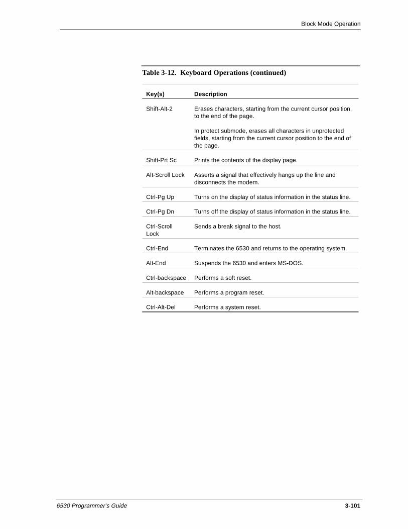
Block Mode Operation
6530 Programmer’s Guide 3-101
Shift-Alt-2 Erases characters, starting from the current cursor position, to the end of the page.
In protect submode, erases all characters in unprotected fields, starting from the current cursor position to the end of the page.
Shift-Prt Sc Prints the contents of the display page.
Alt-Scroll Lock Asserts a signal that effectively hangs up the line and disconnects the modem.
Ctrl-Pg Up Turns on the display of status information in the status line.
Ctrl-Pg Dn Turns off the display of status information in the status line.
Ctrl-Scroll Lock
Sends a break signal to the host.
Ctrl-End Terminates the 6530 and returns to the operating system.
Alt-End Suspends the 6530 and enters MS-DOS.
Ctrl-backspace Performs a soft reset.
Alt-backspace Performs a program reset.
Ctrl-Alt-Del Performs a system reset.
Table 3-12. Keyboard Operations (continued)
Key(s) Description

Block Mode Operation
3-102 6530 Programmer’s Guide
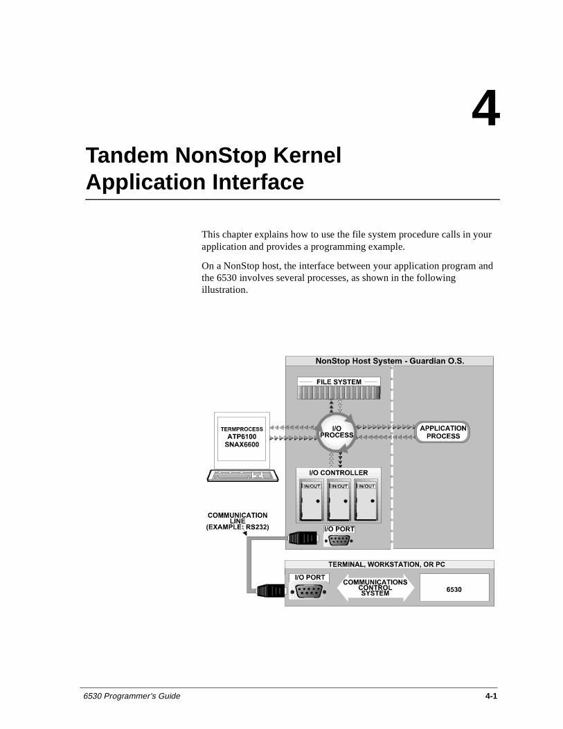
6530 Programmer’s Guide 4-1
4Tandem NonStop Kernel Application Interface
This chapter explains how to use the file system procedure calls in your application and provides a programming example.
On a NonStop host, the interface between your application program and the 6530 involves several processes, as shown in the following illustration.
Tandem NonStop Kernel Application Interface
4-2 6530 Programmer’s Guide
To communicate with the 6530, your application makes calls to the Guardian file system requesting various I/O operations, such as reads and writes. These calls access a set of generic procedures used to perform I/O on different types of devices as well as files. The workstation or PC is treated as a system terminal. The use of generic procedure calls for I/O makes most of the device-specific details transparent to your application.
To establish an I/O channel between the application process and a terminal, your application first calls the OPEN procedure with the device name or logical device number for that terminal. (The device name and corresponding logical device number are assigned during SYSGEN.) The file system then accesses the appropriate I/O process to handle that device. The particular I/O process accessed depends on how the terminal is connected to the host system. For example, terminals connected to the host patch panel are controlled by TERMPROCESS.
The file system handles the transfer of data between your application buffers and the host system buffers. After receiving a request from the file system (initially from your application), the I/O process then handles the transfer of data between the host system and the terminal. Most of the functions of the I/O process are transparent to your application. For example, the I/O process adds the appropriate communications control characters to outgoing data and strips these characters from incoming data. Data is transferred via the I/O controller, which provides the physical and electrical interface between the host system and the communications line to the terminal. The I/O process reports the completion status of an operation to the file system. In the case of an error or device failure, an indication is returned to your application.
At the terminal end, data is transferred through the I/O port and the communications control system (CCS). The CCS checks incoming data for parity and other communications errors and then passes either the data or a communications error message to the 6530. The 6530 then processes the data or displays the communications error on the screen.
The 6530 interprets incoming data as either displayable (graphics) characters, which are stored in display memory or control codes and sequences, which invoke various terminal functions (as described in previous sections). For outgoing data, the 6530 calls the CCS to handle the transfer of data to the host system.
Tandem NonStop Kernel Application Interface
6530 Programmer’s Guide 4-3
File System Procedure Calls
To communicate with a terminal, your application typically first calls the OPEN procedure with the symbolic name for the device.
Then to write data (which can include control codes and escape sequences as well as displayable data) to the terminal, your application calls the WRITE procedure, passing the name of the buffer containing the data to be written.
To read data from the terminal, your application calls the READ procedure, passing the name of the buffer that will contain the data read from the terminal.
A procedure called Write/Read combines a write operation followed by a read operation. Use of the Write/Read procedure ensures that the host system is ready to receive data from a terminal immediately after a message is written to the terminal. This is useful for prompting a terminal user for input in conversational mode. It is also useful for issuing escape sequences that initiate reads from the terminal, for example, read terminal configuration ESC ?).
Note Escape sequences that initiate reads from the terminal should be the only text in the application’s buffer when the Write/Read procedure is called. Although other text in the buffer may appear to operate correctly, timing conflicts in communications and the terminal may cause errors to occur. Other than these escape sequences, the buffer can contain control codes, escape sequences, and displayable data mixed in any logical order.
Also note that the Write/Read procedure does not issue a carriage return/line feed character sequence to the terminal after the write phase of the write/read sequence.
Several other procedures are available for operations on terminals, as summarized in Table 4-1 on page 4-4. See the Tandem NonStop Kernel programmer’s guide for more information on these procedures. Also refer to the appropriate access method manual for terminals controlled by I/O processes other than TERMPROCESS.
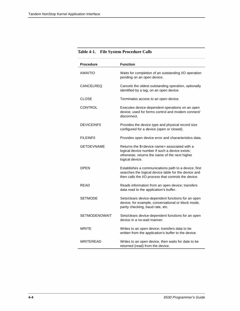
Tandem NonStop Kernel Application Interface
4-4 6530 Programmer’s Guide
Table 4-1. File System Procedure Calls
Procedure Function
AWAITIO Waits for completion of an outstanding I/O operation pending on an open device.
CANCELREQ Cancels the oldest outstanding operation, optionally identified by a tag, on an open device.
CLOSE Terminates access to an open device.
CONTROL Executes device-dependent operations on an open device; used for forms control and modem connect/disconnect.
DEVICEINF0 Provides the device type and physical record size configured for a device (open or closed).
FILEINF0 Provides open device error and characteristics data.
GETDEVNAME Returns the $<device name> associated with a logical device number if such a device exists; otherwise, returns the name of the next higher logical device.
OPEN Establishes a communications path to a device; first searches the logical device table for the device and then calls the I/O process that controls the device.
READ Reads information from an open device; transfers data read to the application’s buffer.
SETMODE Sets/clears device-dependent functions for an open device; for example, conversational or block mode, parity checking, baud rate, etc.
SETMODENOWAIT Sets/clears device-dependent functions for an open device in a no-wait manner.
WRITE Writes to an open device; transfers data to be written from the application’s buffer to the device.
WRITEREAD Writes to an open device, then waits for date to be returned (read) from the device.
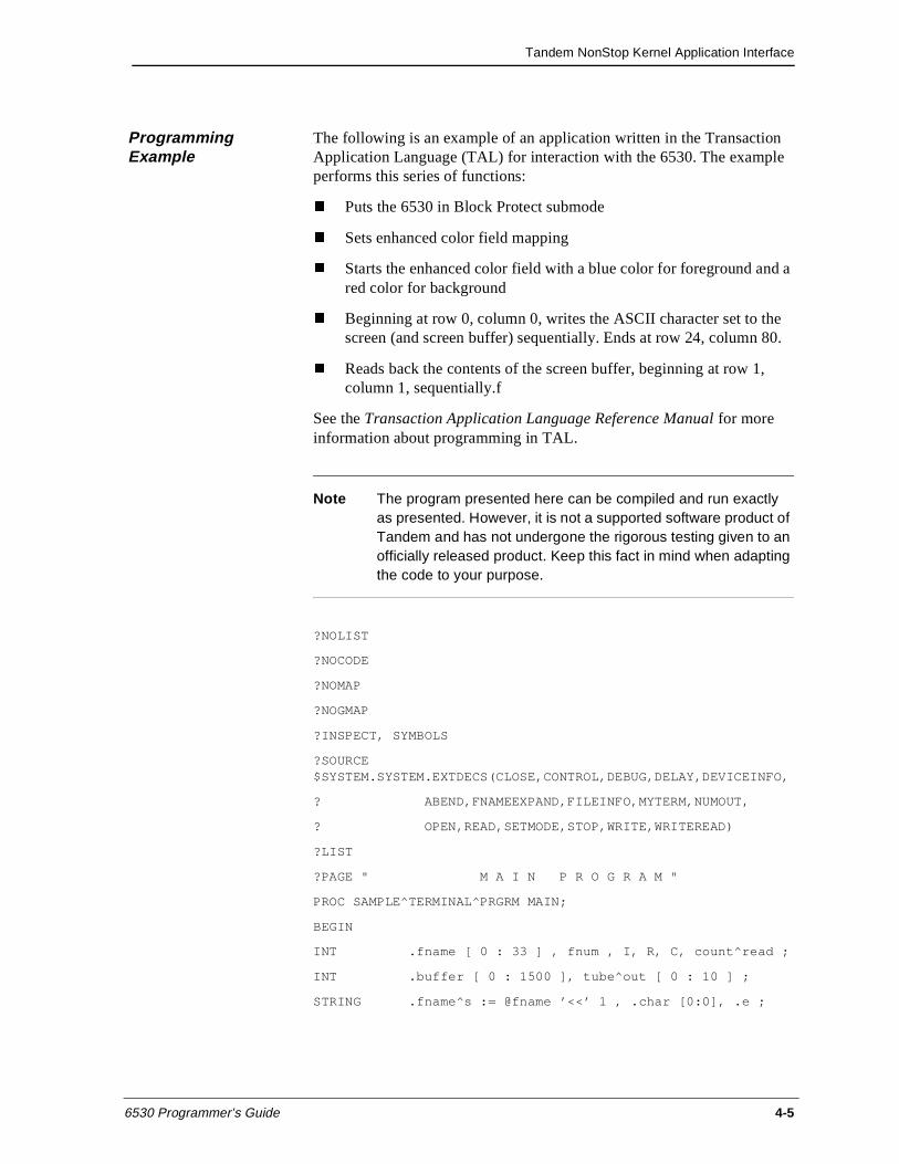
Tandem NonStop Kernel Application Interface
6530 Programmer’s Guide 4-5
Programming Example
The following is an example of an application written in the Transaction Application Language (TAL) for interaction with the 6530. The example performs this series of functions:
n Puts the 6530 in Block Protect submode
n Sets enhanced color field mapping
n Starts the enhanced color field with a blue color for foreground and a red color for background
n Beginning at row 0, column 0, writes the ASCII character set to the screen (and screen buffer) sequentially. Ends at row 24, column 80.
n Reads back the contents of the screen buffer, beginning at row 1, column 1, sequentially.f
See the Transaction Application Language Reference Manual for more information about programming in TAL.
Note The program presented here can be compiled and run exactly as presented. However, it is not a supported software product of Tandem and has not undergone the rigorous testing given to an officially released product. Keep this fact in mind when adapting the code to your purpose.
?NOLIST
?NOCODE
?NOMAP
?NOGMAP
?INSPECT, SYMBOLS
?SOURCE $SYSTEM.SYSTEM.EXTDECS(CLOSE,CONTROL,DEBUG,DELAY,DEVICEINFO,
? ABEND,FNAMEEXPAND,FILEINFO,MYTERM,NUMOUT,
? OPEN,READ,SETMODE,STOP,WRITE,WRITEREAD)
?LIST
?PAGE " M A I N P R O G R A M "
PROC SAMPLE^TERMINAL^PRGRM MAIN;
BEGIN
INT .fname [ 0 : 33 ] , fnum , I, R, C, count^read ;
INT .buffer [ 0 : 1500 ], tube^out [ 0 : 10 ] ;
STRING .fname^s := @fname ’<<’ 1 , .char [0:0], .e ;
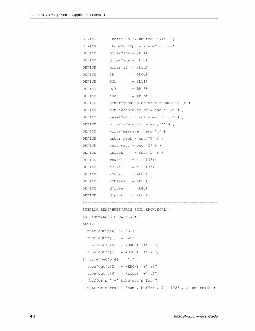
Tandem NonStop Kernel Application Interface
4-6 6530 Programmer’s Guide
STRING .buffer^s := @buffer ’<<’ 1 ;
STRING .tube^out^p := @tube^out ’<<’ 1;
DEFINE order^sba = %h11# ;
DEFINE order^sca = %h13# ;
DEFINE order^sf = %h1d# ;
DEFINE CR = %h0d# ;
DEFINE DC1 = %h11# ;
DEFINE DC3 = %h13# ;
DEFINE esc = %h1b# ;
DEFINE order^read^color^conf = esc,"-u" # ;
DEFINE set^enhance^color = esc,"-1x" # ;
DEFINE reset^color^conf = esc,"-1;t" # ;
DEFINE order^sfe^color = esc,"‘" # ;
DEFINE write^message = esc,"o" #;
DEFINE enter^prot = esc,"W" # ;
DEFINE exit^prot = esc,"X" # ;
DEFINE unlock = esc,"b" # ;
DEFINE row(a) = a + %37#;
DEFINE col(a) = a + %37#;
DEFINE v^norm = %h20# ;
DEFINE v^blank = %h28# ;
DEFINE d^free = %h40# ;
DEFINE d^prot = %h60# ;
!-----------------------------------------------------------
SUBPROC READ^BUFF(SROW,SCOL,EROW,ECOL);
INT SROW,SCOL,EROW,ECOL;
BEGIN
tube^out^p[0] := ESC;
tube^out^p[1] := "=";
tube^out^p[2] := (SROW) ’+’ %37;
tube^out^p[3] := (SCOL) ’+’ %37;
! tube^out^p[4] := ";";
tube^out^p[5] := (EROW) ’+’ %37;
tube^out^p[6] := (ECOL) ’+’ %37;
buffer^s ’:=’ tube^out^p for 7;
CALL writeread ( fnum , buffer , 7 , 1023 , count^read) ;
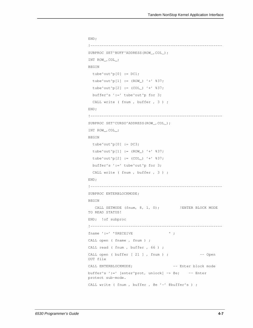
Tandem NonStop Kernel Application Interface
6530 Programmer’s Guide 4-7
END;
!-----------------------------------------------------------
SUBPROC SET^BUFF^ADDRESS(ROW_,COL_);
INT ROW_,COL_;
BEGIN
tube^out^p[0] := DC1;
tube^out^p[1] := (ROW_) ’+’ %37;
tube^out^p[2] := (COL_) ’+’ %37;
buffer^s ’:=’ tube^out^p for 3;
CALL write ( fnum , buffer , 3 ) ;
END;
!-----------------------------------------------------------
SUBPROC SET^CURSO^ADDRESS(ROW_,COL_);
INT ROW_,COL_;
BEGIN
tube^out^p[0] := DC3;
tube^out^p[1] := (ROW_) ’+’ %37;
tube^out^p[2] := (COL_) ’+’ %37;
buffer^s ’:=’ tube^out^p for 3;
CALL write ( fnum , buffer , 3 ) ;
END;
!-----------------------------------------------------------
SUBPROC ENTERBLOCKMODE;
BEGIN
CALL SETMODE (fnum, 8, 1, 0); !ENTER BLOCK MODE TO READ STATUS!
END; !of subproc
!-----------------------------------------------------------
fname ’:=’ "$RECEIVE " ;
CALL open ( fname , fnum ) ;
CALL read ( fnum , buffer , 66 ) ;
CALL open ( buffer [ 21 ] , fnum ) ; -- Open OUT file
CALL ENTERBLOCKMODE; -- Enter block mode
buffer^s ’:=’ [enter^prot, unlock] -> @e; -- Enter protect sub-mode.
CALL write ( fnum , buffer , @e ’-’ @buffer^s ) ;
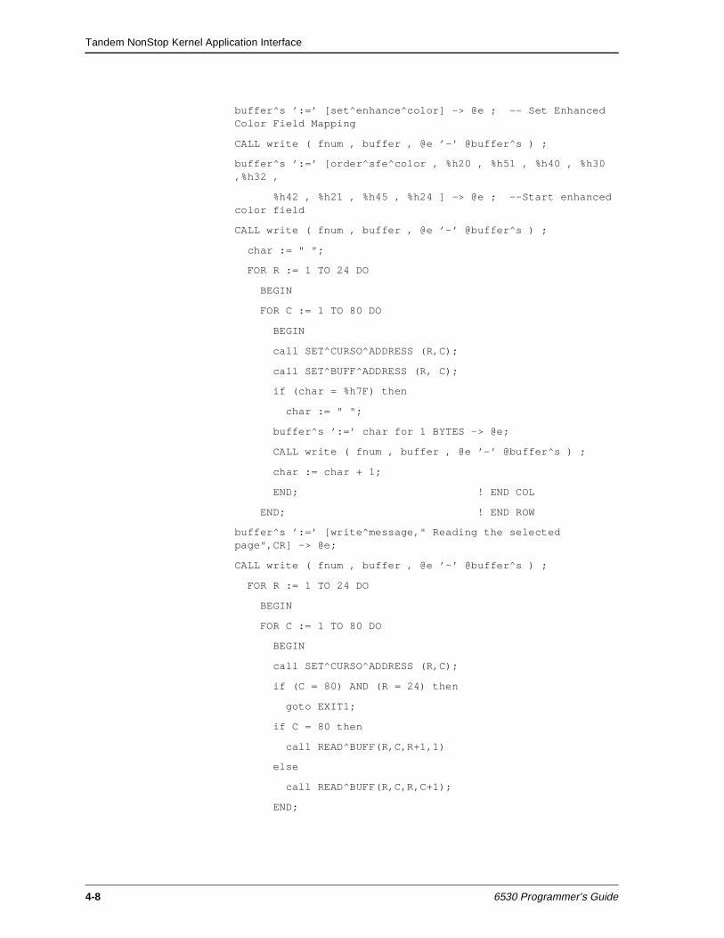
Tandem NonStop Kernel Application Interface
4-8 6530 Programmer’s Guide
buffer^s ’:=’ [set^enhance^color] -> @e ; -- Set Enhanced Color Field Mapping
CALL write ( fnum , buffer , @e ’-’ @buffer^s ) ;
buffer^s ’:=’ [order^sfe^color , %h20 , %h51 , %h40 , %h30 ,%h32 ,
%h42 , %h21 , %h45 , %h24 ] -> @e ; --Start enhanced color field
CALL write ( fnum , buffer , @e ’-’ @buffer^s ) ;
char := " ";
FOR R := 1 TO 24 DO
BEGIN
FOR C := 1 TO 80 DO
BEGIN
call SET^CURSO^ADDRESS (R,C);
call SET^BUFF^ADDRESS (R, C);
if (char = %h7F) then
char := " ";
buffer^s ’:=’ char for 1 BYTES -> @e;
CALL write ( fnum , buffer , @e ’-’ @buffer^s ) ;
char := char + 1;
END; ! END COL
END; ! END ROW
buffer^s ’:=’ [write^message," Reading the selected page",CR] -> @e;
CALL write ( fnum , buffer , @e ’-’ @buffer^s ) ;
FOR R := 1 TO 24 DO
BEGIN
FOR C := 1 TO 80 DO
BEGIN
call SET^CURSO^ADDRESS (R,C);
if (C = 80) AND (R = 24) then
goto EXIT1;
if C = 80 then
call READ^BUFF(R,C,R+1,1)
else
call READ^BUFF(R,C,R,C+1);
END;
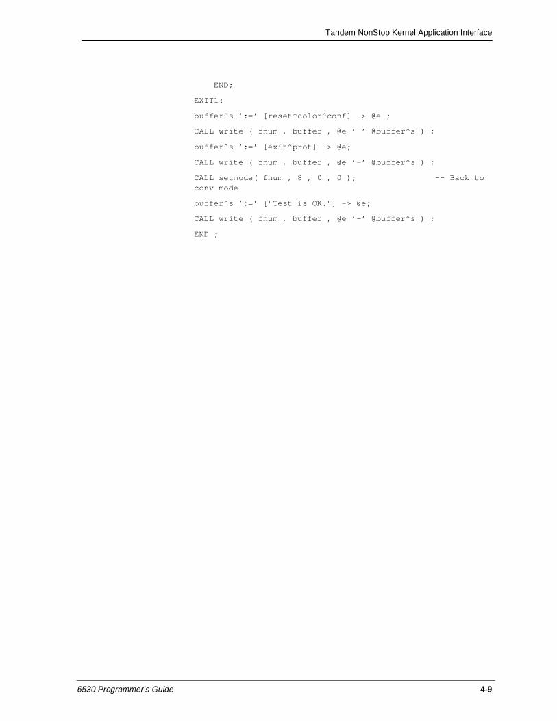
Tandem NonStop Kernel Application Interface
6530 Programmer’s Guide 4-9
END;
EXIT1:
buffer^s ’:=’ [reset^color^conf] -> @e ;
CALL write ( fnum , buffer , @e ’-’ @buffer^s ) ;
buffer^s ’:=’ [exit^prot] -> @e;
CALL write ( fnum , buffer , @e ’-’ @buffer^s ) ;
CALL setmode( fnum , 8 , 0 , 0 ); -- Back to conv mode
buffer^s ’:=’ ["Test is OK."] -> @e;
CALL write ( fnum , buffer , @e ’-’ @buffer^s ) ;
END ;

Tandem NonStop Kernel Application Interface
4-10 6530 Programmer’s Guide
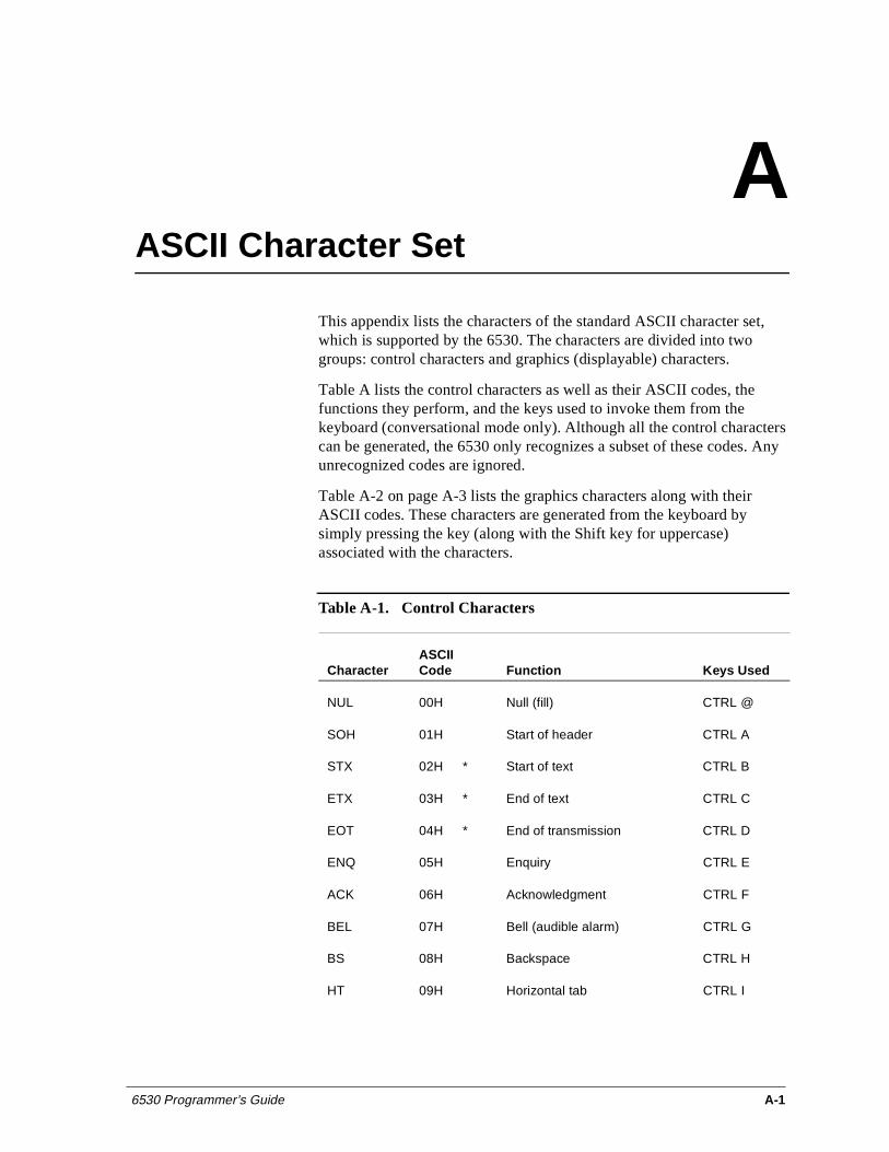
6530 Programmer’s Guide A-1
AASCII Character Set
This appendix lists the characters of the standard ASCII character set, which is supported by the 6530. The characters are divided into two groups: control characters and graphics (displayable) characters.
Table A lists the control characters as well as their ASCII codes, the functions they perform, and the keys used to invoke them from the keyboard (conversational mode only). Although all the control characters can be generated, the 6530 only recognizes a subset of these codes. Any unrecognized codes are ignored.
Table A-2 on page A-3 lists the graphics characters along with their ASCII codes. These characters are generated from the keyboard by simply pressing the key (along with the Shift key for uppercase) associated with the characters.
Table A-1. Control Characters
CharacterASCII Code Function Keys Used
NUL 00H Null (fill) CTRL @
SOH 01H Start of header CTRL A
STX 02H * Start of text CTRL B
ETX 03H * End of text CTRL C
EOT 04H * End of transmission CTRL D
ENQ 05H Enquiry CTRL E
ACK 06H Acknowledgment CTRL F
BEL 07H Bell (audible alarm) CTRL G
BS 08H Backspace CTRL H
HT 09H Horizontal tab CTRL I
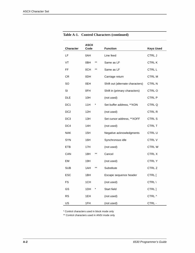
ASCII Character Set
A-2 6530 Programmer’s Guide
* Control characters used in block mode only
** Control characters used in ANSI mode only
LF 0AH Line feed CTRL J
VT 0BH ** Same as LF CTRL K
FF 0CH ** Same as LF CTRL L
CR 0DH Carriage return CTRL M
SO 0EH Shift out (alternate characters) CTRL N
SI 0FH Shift in (primary characters) CTRL O
DLE 10H (not used) CTRL P
DC1 11H * Set buffer address, **XON CTRL Q
DC2 12H (not used) CTRL R
DC3 13H Set cursor address, **XOFF CTRL S
DC4 14H (not used) CTRL T
NAK 15H Negative acknowledgments CTRL U
SYN 16H Synchronous idle CTRL V
ETB 17H (not used) CTRL W
CAN 18H ** Cancel CTRL X
EM 19H (not used) CTRL Y
SUB 1AH ** Substitute CTRL Z
ESC 1BH Escape sequence header CTRL [
FS 1CH (not used) CTRL \
GS 1DH * Start field CTRL ]
RS 1EH (not used) CTRL ^
US 1FH (not used) CTRL -
Table A-1. Control Characters (continued)
CharacterASCII Code Function Keys Used
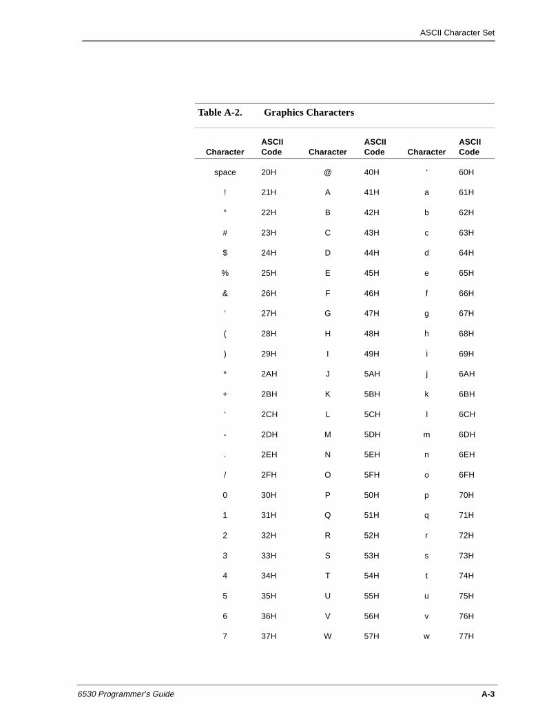
ASCII Character Set
6530 Programmer’s Guide A-3
Table A-2. Graphics Characters
CharacterASCII Code Character
ASCII Code Character
ASCII Code
space 20H @ 40H ‘ 60H
! 21H A 41H a 61H
“ 22H B 42H b 62H
# 23H C 43H c 63H
$ 24H D 44H d 64H
% 25H E 45H e 65H
& 26H F 46H f 66H
‘ 27H G 47H g 67H
( 28H H 48H h 68H
) 29H I 49H i 69H
* 2AH J 5AH j 6AH
+ 2BH K 5BH k 6BH
‘ 2CH L 5CH l 6CH
- 2DH M 5DH m 6DH
. 2EH N 5EH n 6EH
/ 2FH O 5FH o 6FH
0 30H P 50H p 70H
1 31H Q 51H q 71H
2 32H R 52H r 72H
3 33H S 53H s 73H
4 34H T 54H t 74H
5 35H U 55H u 75H
6 36H V 56H v 76H
7 37H W 57H w 77H
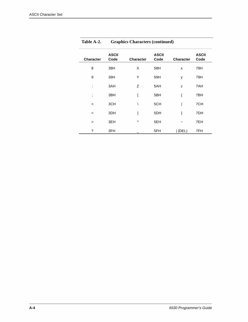
ASCII Character Set
A-4 6530 Programmer’s Guide
8 38H X 58H x 78H
9 39H Y 59H y 79H
: 3AH Z 5AH z 7AH
; 3BH [ 5BH { 7BH
< 3CH \ 5CH | 7CH
= 3DH ] 5DH } 7DH
> 3EH ^ 5EH ~ 7EH
? 3FH _ 5FH | (DEL) 7FH
Table A-2. Graphics Characters (continued)
CharacterASCII Code Character
ASCII Code Character
ASCII Code
6530 Programmer’s Guide B-1
BInternational Characters
The 6530 supports two ISO standards used for international characters:
n ISO 646 for character sets (including the US ASCII character set) that comprise 96 7-bit codes.
n ISO 8859 for character sets that comprise 256 8-bit codes.
The use of the eighth bit in ISO 8859 character sets enables these sets to include non-ASCII characters, such as à or ç.
In order to include non-ASCII characters when the 7-bit ISO 646 character set is used, the 6530 utilizes a character substitution method in which a character in the ASCII set is replaced by one of the characters from another language. For example, in the English UK character set, the # character is replaced by the £ character.
Table B-1 lists the codes, the ASCII characters that are replaced, and the corresponding characters for each supported language that uses the 7-bit ISO 646 standard.
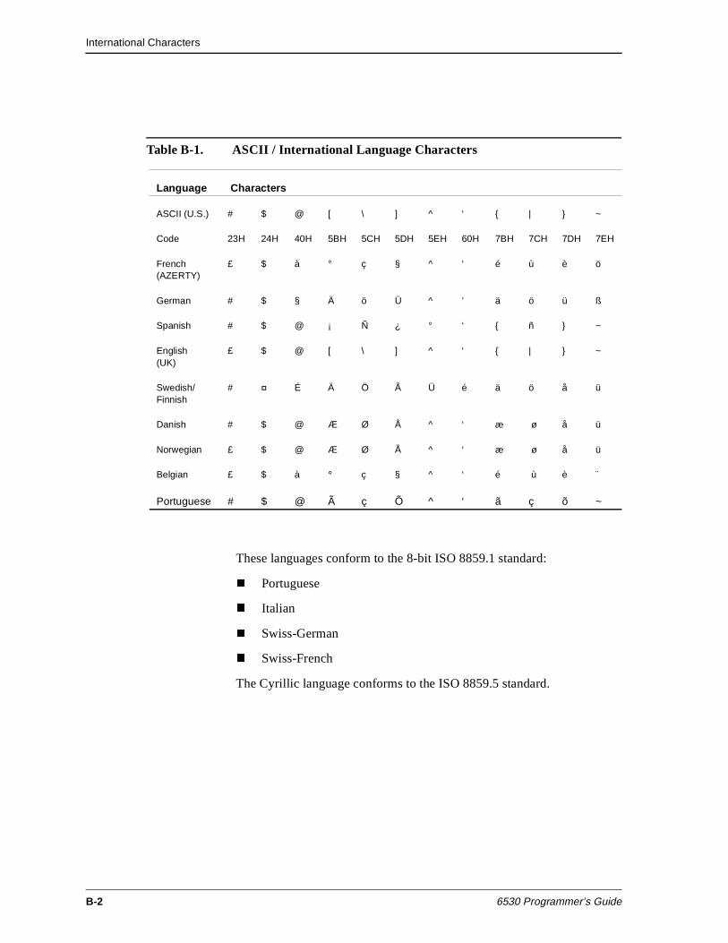
International Characters
B-2 6530 Programmer’s Guide
These languages conform to the 8-bit ISO 8859.1 standard:
n Portuguese
n Italian
n Swiss-German
n Swiss-French
The Cyrillic language conforms to the ISO 8859.5 standard.
Table B-1. ASCII / International Language Characters
Language Characters
ASCII (U.S.) # $ @ [ \ ] ^ ‘ { | } ~
Code 23H 24H 40H 5BH 5CH 5DH 5EH 60H 7BH 7CH 7DH 7EH
French(AZERTY)
£ $ à ° ç § ^ ‘ é ù è ö
German # $ § Ä ö Ü ^ ’ ä ö ü ß
Spanish # $ @ ¡ Ñ ¿ ° ‘ { ñ } ~
English(UK)
£ $ @ [ \ ] ^ ‘ { | } ~
Swedish/Finnish
# ¤ É Ä Ö Å Ü é ä ö å ü
Danish # $ @ Æ Ø Å ^ ‘ æ ø å ü
Norwegian £ $ @ Æ Ø Å ^ ‘ æ ø å ü
Belgian £ $ à ° ç § ^ ‘ é ù è ¨
Portuguese # $ @ Ã ç Õ ^ ‘ ã ç õ ~
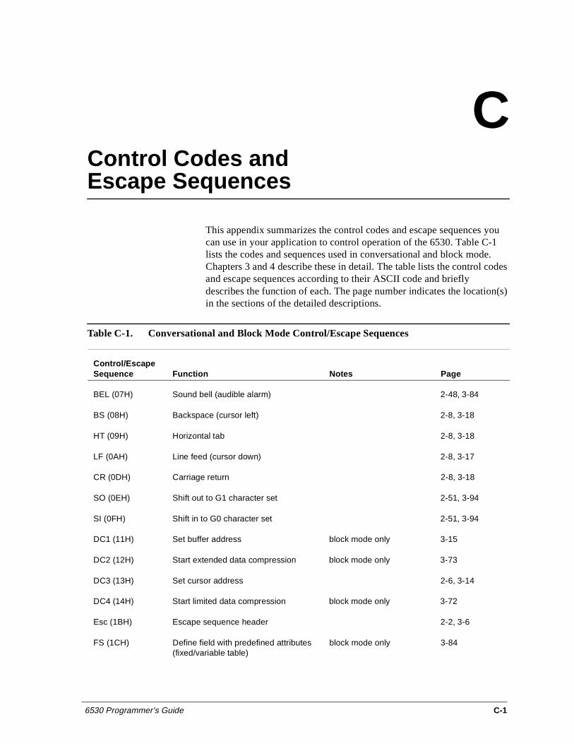
6530 Programmer’s Guide C-1
CControl Codes and Escape Sequences
This appendix summarizes the control codes and escape sequences you can use in your application to control operation of the 6530. Table C-1 lists the codes and sequences used in conversational and block mode. Chapters 3 and 4 describe these in detail. The table lists the control codes and escape sequences according to their ASCII code and briefly describes the function of each. The page number indicates the location(s) in the sections of the detailed descriptions.
Table C-1. Conversational and Block Mode Control/Escape Sequences
Control/Escape Sequence Function Notes Page
BEL (07H) Sound bell (audible alarm) 2-48, 3-84
BS (08H) Backspace (cursor left) 2-8, 3-18
HT (09H) Horizontal tab 2-8, 3-18
LF (0AH) Line feed (cursor down) 2-8, 3-17
CR (0DH) Carriage return 2-8, 3-18
SO (0EH) Shift out to G1 character set 2-51, 3-94
SI (0FH) Shift in to G0 character set 2-51, 3-94
DC1 (11H) Set buffer address block mode only 3-15
DC2 (12H) Start extended data compression block mode only 3-73
DC3 (13H) Set cursor address 2-6, 3-14
DC4 (14H) Start limited data compression block mode only 3-72
Esc (1BH) Escape sequence header 2-2, 3-6
FS (1CH) Define field with predefined attributes (fixed/variable table)
block mode only 3-84
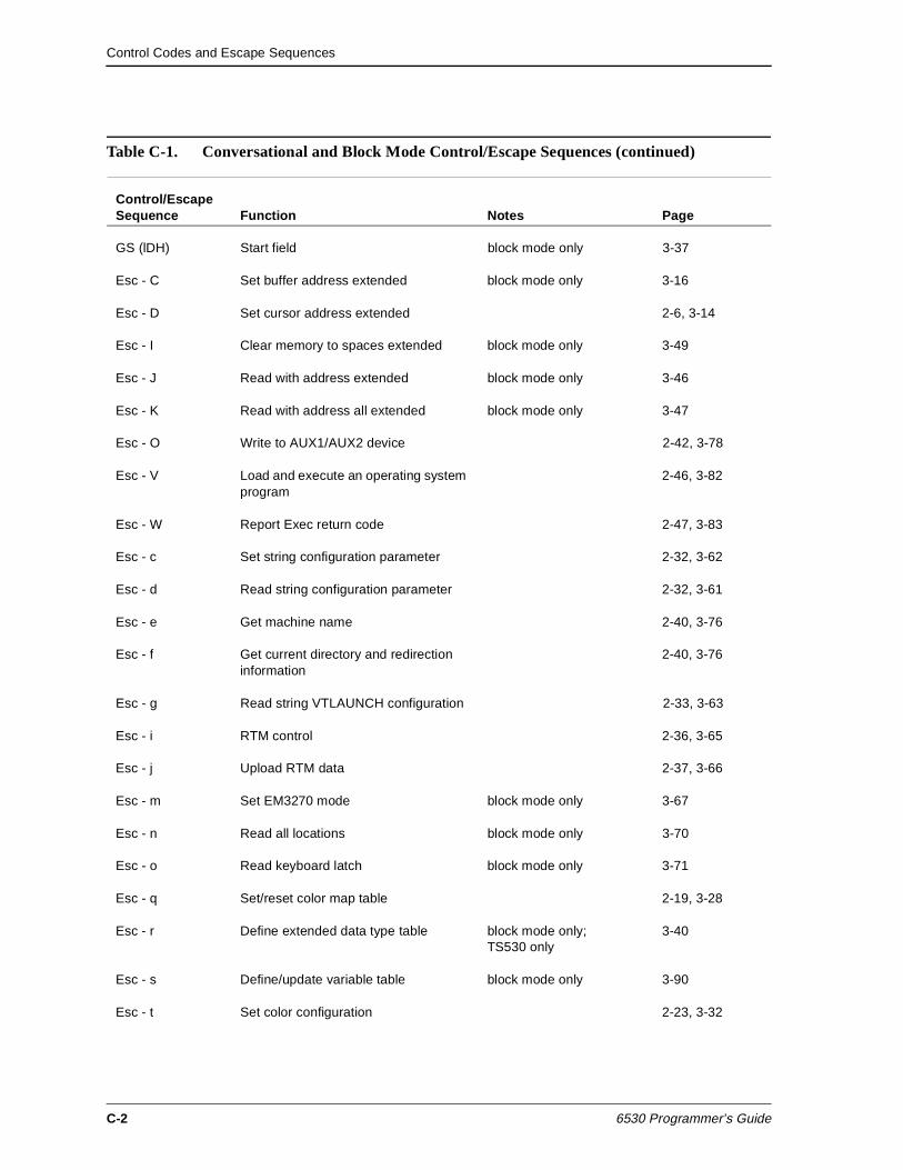
Control Codes and Escape Sequences
C-2 6530 Programmer’s Guide
GS (lDH) Start field block mode only 3-37
Esc - C Set buffer address extended block mode only 3-16
Esc - D Set cursor address extended 2-6, 3-14
Esc - I Clear memory to spaces extended block mode only 3-49
Esc - J Read with address extended block mode only 3-46
Esc - K Read with address all extended block mode only 3-47
Esc - O Write to AUX1/AUX2 device 2-42, 3-78
Esc - V Load and execute an operating system program
2-46, 3-82
Esc - W Report Exec return code 2-47, 3-83
Esc - c Set string configuration parameter 2-32, 3-62
Esc - d Read string configuration parameter 2-32, 3-61
Esc - e Get machine name 2-40, 3-76
Esc - f Get current directory and redirection information
2-40, 3-76
Esc - g Read string VTLAUNCH configuration 2-33, 3-63
Esc - i RTM control 2-36, 3-65
Esc - j Upload RTM data 2-37, 3-66
Esc - m Set EM3270 mode block mode only 3-67
Esc - n Read all locations block mode only 3-70
Esc - o Read keyboard latch block mode only 3-71
Esc - q Set/reset color map table 2-19, 3-28
Esc - r Define extended data type table block mode only; TS530 only
3-40
Esc - s Define/update variable table block mode only 3-90
Esc - t Set color configuration 2-23, 3-32
Table C-1. Conversational and Block Mode Control/Escape Sequences (continued)
Control/Escape Sequence Function Notes Page
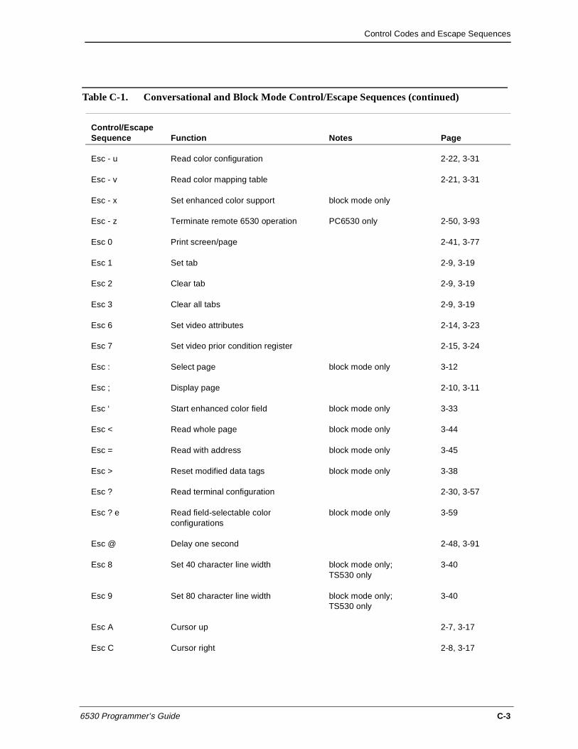
Control Codes and Escape Sequences
6530 Programmer’s Guide C-3
Esc - u Read color configuration 2-22, 3-31
Esc - v Read color mapping table 2-21, 3-31
Esc - x Set enhanced color support block mode only
Esc - z Terminate remote 6530 operation PC6530 only 2-50, 3-93
Esc 0 Print screen/page 2-41, 3-77
Esc 1 Set tab 2-9, 3-19
Esc 2 Clear tab 2-9, 3-19
Esc 3 Clear all tabs 2-9, 3-19
Esc 6 Set video attributes 2-14, 3-23
Esc 7 Set video prior condition register 2-15, 3-24
Esc : Select page block mode only 3-12
Esc ; Display page 2-10, 3-11
Esc ‘ Start enhanced color field block mode only 3-33
Esc < Read whole page block mode only 3-44
Esc = Read with address block mode only 3-45
Esc > Reset modified data tags block mode only 3-38
Esc ? Read terminal configuration 2-30, 3-57
Esc ? e Read field-selectable color configurations
block mode only 3-59
Esc @ Delay one second 2-48, 3-91
Esc 8 Set 40 character line width block mode only;TS530 only
3-40
Esc 9 Set 80 character line width block mode only;TS530 only
3-40
Esc A Cursor up 2-7, 3-17
Esc C Cursor right 2-8, 3-17
Table C-1. Conversational and Block Mode Control/Escape Sequences (continued)
Control/Escape Sequence Function Notes Page
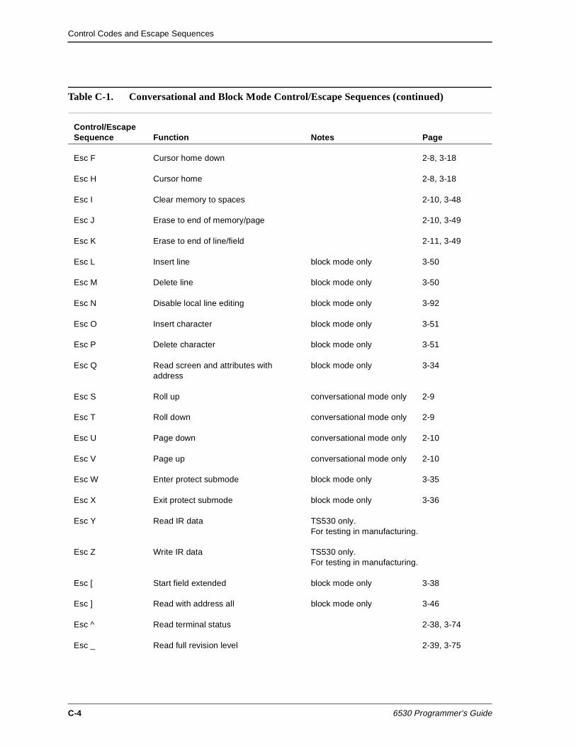
Control Codes and Escape Sequences
C-4 6530 Programmer’s Guide
Esc F Cursor home down 2-8, 3-18
Esc H Cursor home 2-8, 3-18
Esc I Clear memory to spaces 2-10, 3-48
Esc J Erase to end of memory/page 2-10, 3-49
Esc K Erase to end of line/field 2-11, 3-49
Esc L Insert line block mode only 3-50
Esc M Delete line block mode only 3-50
Esc N Disable local line editing block mode only 3-92
Esc O Insert character block mode only 3-51
Esc P Delete character block mode only 3-51
Esc Q Read screen and attributes with address
block mode only 3-34
Esc S Roll up conversational mode only 2-9
Esc T Roll down conversational mode only 2-9
Esc U Page down conversational mode only 2-10
Esc V Page up conversational mode only 2-10
Esc W Enter protect submode block mode only 3-35
Esc X Exit protect submode block mode only 3-36
Esc Y Read IR data TS530 only. For testing in manufacturing.
Esc Z Write IR data TS530 only. For testing in manufacturing.
Esc [ Start field extended block mode only 3-38
Esc ] Read with address all block mode only 3-46
Esc ^ Read terminal status 2-38, 3-74
Esc _ Read full revision level 2-39, 3-75
Table C-1. Conversational and Block Mode Control/Escape Sequences (continued)
Control/Escape Sequence Function Notes Page
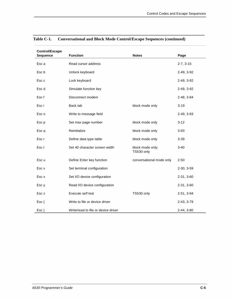
Control Codes and Escape Sequences
6530 Programmer’s Guide C-5
Esc a Read cursor address 2-7, 3-15
Esc b Unlock keyboard 2-49, 3-92
Esc c Lock keyboard 2-49, 3-92
Esc d Simulate function key 2-49, 3-92
Esc f Disconnect modem 2-48, 3-84
Esc i Back tab block mode only 3-19
Esc o Write to message field 2-49, 3-93
Esc p Set max page number block mode only 3-12
Esc q Reinitialize block mode only 3-93
Esc r Define data type table block mode only 3-39
Esc t Set 40 character screen width block mode only; TS530 only
3-40
Esc u Define Enter key function conversational mode only 2-50
Esc v Set terminal configuration 2-30, 3-59
Esc x Set I/O device configuration 2-31, 3-60
Esc y Read I/O device configuration 2-31, 3-60
Esc z Execute self test TS530 only 2-51, 3-94
Esc { Write to file or device driver 2-43, 3-79
Esc } Write/read to file or device driver 2-44, 3-80
Table C-1. Conversational and Block Mode Control/Escape Sequences (continued)
Control/Escape Sequence Function Notes Page

Control Codes and Escape Sequences
C-6 6530 Programmer’s Guide
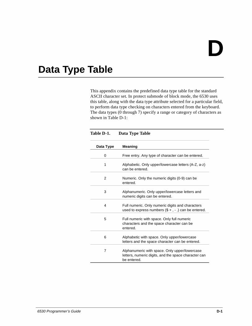
6530 Programmer’s Guide D-1
DData Type Table
This appendix contains the predefined data type table for the standard ASCII character set. In protect submode of block mode, the 6530 uses this table, along with the data type attribute selected for a particular field, to perform data type checking on characters entered from the keyboard. The data types (0 through 7) specify a range or category of characters as shown in Table D-1:
Table D-1. Data Type Table
Data Type Meaning
0 Free entry. Any type of character can be entered.
1 Alphabetic. Only upper/lowercase letters (A-Z, a-z) can be entered.
2 Numeric. Only the numeric digits (0-9) can be entered.
3 Alphanumeric. Only upper/lowercase letters and numeric digits can be entered.
4 Full numeric. Only numeric digits and characters used to express numbers ($ + , - .) can be entered.
5 Full numeric with space. Only full numeric characters and the space character can be entered.
6 Alphabetic with space. Only upper/lowercase letters and the space character can be entered.
7 Alphanumeric with space. Only upper/lowercase letters, numeric digits, and the space character can be entered.
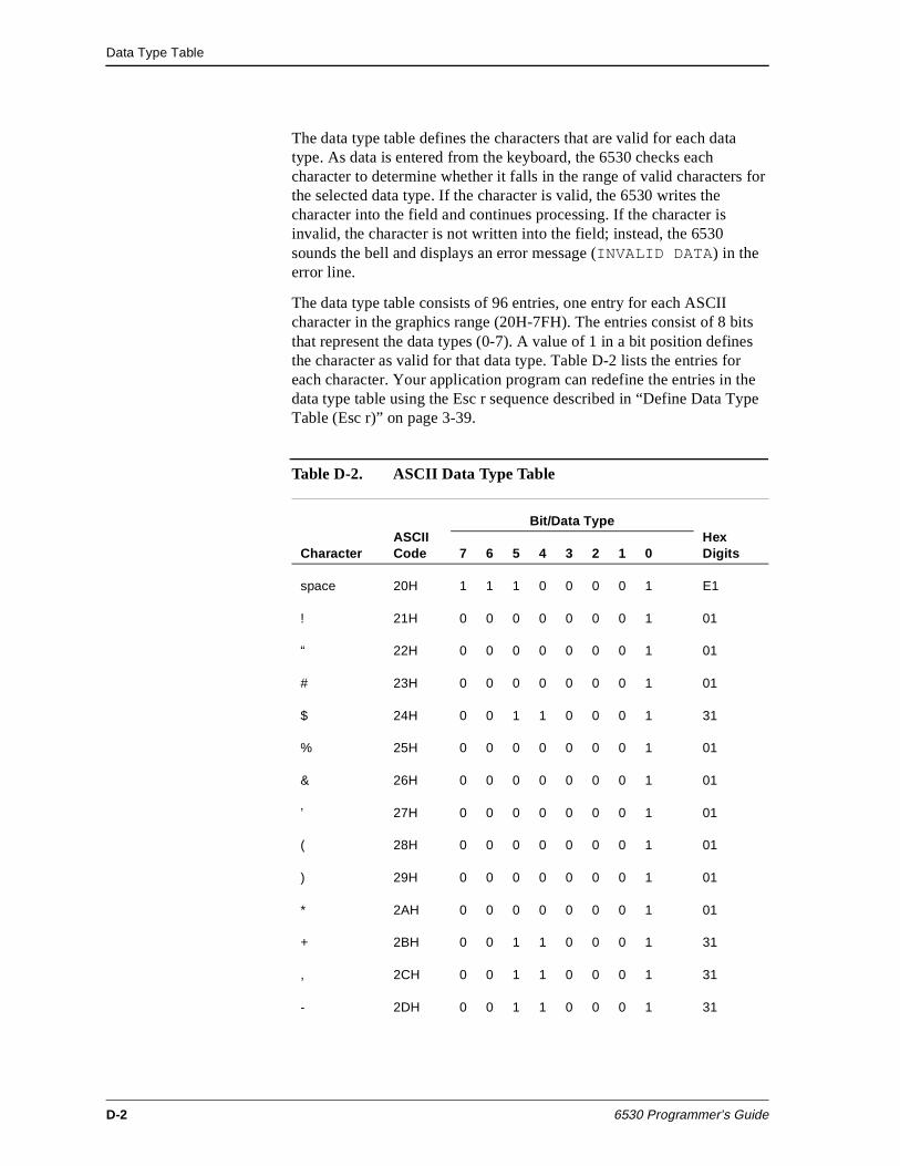
Data Type Table
D-2 6530 Programmer’s Guide
The data type table defines the characters that are valid for each data type. As data is entered from the keyboard, the 6530 checks each character to determine whether it falls in the range of valid characters for the selected data type. If the character is valid, the 6530 writes the character into the field and continues processing. If the character is invalid, the character is not written into the field; instead, the 6530 sounds the bell and displays an error message (INVALID DATA) in the error line.
The data type table consists of 96 entries, one entry for each ASCII character in the graphics range (20H-7FH). The entries consist of 8 bits that represent the data types (0-7). A value of 1 in a bit position defines the character as valid for that data type. Table D-2 lists the entries for each character. Your application program can redefine the entries in the data type table using the Esc r sequence described in “Define Data Type Table (Esc r)” on page 3-39.
Table D-2. ASCII Data Type Table
Character ASCII Code
Bit/Data TypeHex Digits 7 6 5 4 3 2 1 0
space 20H 1 1 1 0 0 0 0 1 E1
! 21H 0 0 0 0 0 0 0 1 01
“ 22H 0 0 0 0 0 0 0 1 01
# 23H 0 0 0 0 0 0 0 1 01
$ 24H 0 0 1 1 0 0 0 1 31
% 25H 0 0 0 0 0 0 0 1 01
& 26H 0 0 0 0 0 0 0 1 01
’ 27H 0 0 0 0 0 0 0 1 01
( 28H 0 0 0 0 0 0 0 1 01
) 29H 0 0 0 0 0 0 0 1 01
* 2AH 0 0 0 0 0 0 0 1 01
+ 2BH 0 0 1 1 0 0 0 1 31
, 2CH 0 0 1 1 0 0 0 1 31
- 2DH 0 0 1 1 0 0 0 1 31
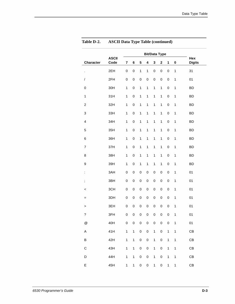
Data Type Table
6530 Programmer’s Guide D-3
. 2EH 0 0 1 1 0 0 0 1 31
/ 2FH 0 0 0 0 0 0 0 1 01
0 30H 1 0 1 1 1 1 0 1 BD
1 31H 1 0 1 1 1 1 0 1 BD
2 32H 1 0 1 1 1 1 0 1 BD
3 33H 1 0 1 1 1 1 0 1 BD
4 34H 1 0 1 1 1 1 0 1 BD
5 35H 1 0 1 1 1 1 0 1 BD
6 36H 1 0 1 1 1 1 0 1 BD
7 37H 1 0 1 1 1 1 0 1 BD
8 38H 1 0 1 1 1 1 0 1 BD
9 39H 1 0 1 1 1 1 0 1 BD
: 3AH 0 0 0 0 0 0 0 1 01
; 3BH 0 0 0 0 0 0 0 1 01
< 3CH 0 0 0 0 0 0 0 1 01
= 3DH 0 0 0 0 0 0 0 1 01
> 3EH 0 0 0 0 0 0 0 1 01
? 3FH 0 0 0 0 0 0 0 1 01
@ 40H 0 0 0 0 0 0 0 1 01
A 41H 1 1 0 0 1 0 1 1 CB
B 42H 1 1 0 0 1 0 1 1 CB
C 43H 1 1 0 0 1 0 1 1 CB
D 44H 1 1 0 0 1 0 1 1 CB
E 45H 1 1 0 0 1 0 1 1 CB
Table D-2. ASCII Data Type Table (continued)
Character ASCII Code
Bit/Data TypeHex Digits 7 6 5 4 3 2 1 0
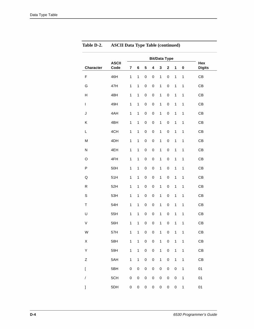
Data Type Table
D-4 6530 Programmer’s Guide
F 46H 1 1 0 0 1 0 1 1 CB
G 47H 1 1 0 0 1 0 1 1 CB
H 48H 1 1 0 0 1 0 1 1 CB
I 49H 1 1 0 0 1 0 1 1 CB
J 4AH 1 1 0 0 1 0 1 1 CB
K 4BH 1 1 0 0 1 0 1 1 CB
L 4CH 1 1 0 0 1 0 1 1 CB
M 4DH 1 1 0 0 1 0 1 1 CB
N 4EH 1 1 0 0 1 0 1 1 CB
O 4FH 1 1 0 0 1 0 1 1 CB
P 50H 1 1 0 0 1 0 1 1 CB
Q 51H 1 1 0 0 1 0 1 1 CB
R 52H 1 1 0 0 1 0 1 1 CB
S 53H 1 1 0 0 1 0 1 1 CB
T 54H 1 1 0 0 1 0 1 1 CB
U 55H 1 1 0 0 1 0 1 1 CB
V 56H 1 1 0 0 1 0 1 1 CB
W 57H 1 1 0 0 1 0 1 1 CB
X 58H 1 1 0 0 1 0 1 1 CB
Y 59H 1 1 0 0 1 0 1 1 CB
Z 5AH 1 1 0 0 1 0 1 1 CB
[ 5BH 0 0 0 0 0 0 0 1 01
/ 5CH 0 0 0 0 0 0 0 1 01
] 5DH 0 0 0 0 0 0 0 1 01
Table D-2. ASCII Data Type Table (continued)
Character ASCII Code
Bit/Data TypeHex Digits 7 6 5 4 3 2 1 0
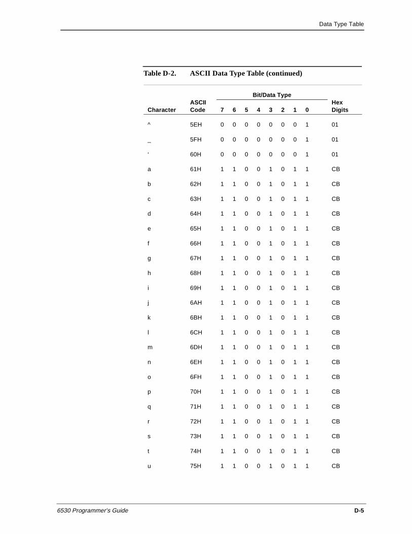
Data Type Table
6530 Programmer’s Guide D-5
^ 5EH 0 0 0 0 0 0 0 1 01
_ 5FH 0 0 0 0 0 0 0 1 01
‘ 60H 0 0 0 0 0 0 0 1 01
a 61H 1 1 0 0 1 0 1 1 CB
b 62H 1 1 0 0 1 0 1 1 CB
c 63H 1 1 0 0 1 0 1 1 CB
d 64H 1 1 0 0 1 0 1 1 CB
e 65H 1 1 0 0 1 0 1 1 CB
f 66H 1 1 0 0 1 0 1 1 CB
g 67H 1 1 0 0 1 0 1 1 CB
h 68H 1 1 0 0 1 0 1 1 CB
i 69H 1 1 0 0 1 0 1 1 CB
j 6AH 1 1 0 0 1 0 1 1 CB
k 6BH 1 1 0 0 1 0 1 1 CB
l 6CH 1 1 0 0 1 0 1 1 CB
m 6DH 1 1 0 0 1 0 1 1 CB
n 6EH 1 1 0 0 1 0 1 1 CB
o 6FH 1 1 0 0 1 0 1 1 CB
p 70H 1 1 0 0 1 0 1 1 CB
q 71H 1 1 0 0 1 0 1 1 CB
r 72H 1 1 0 0 1 0 1 1 CB
s 73H 1 1 0 0 1 0 1 1 CB
t 74H 1 1 0 0 1 0 1 1 CB
u 75H 1 1 0 0 1 0 1 1 CB
Table D-2. ASCII Data Type Table (continued)
Character ASCII Code
Bit/Data TypeHex Digits 7 6 5 4 3 2 1 0
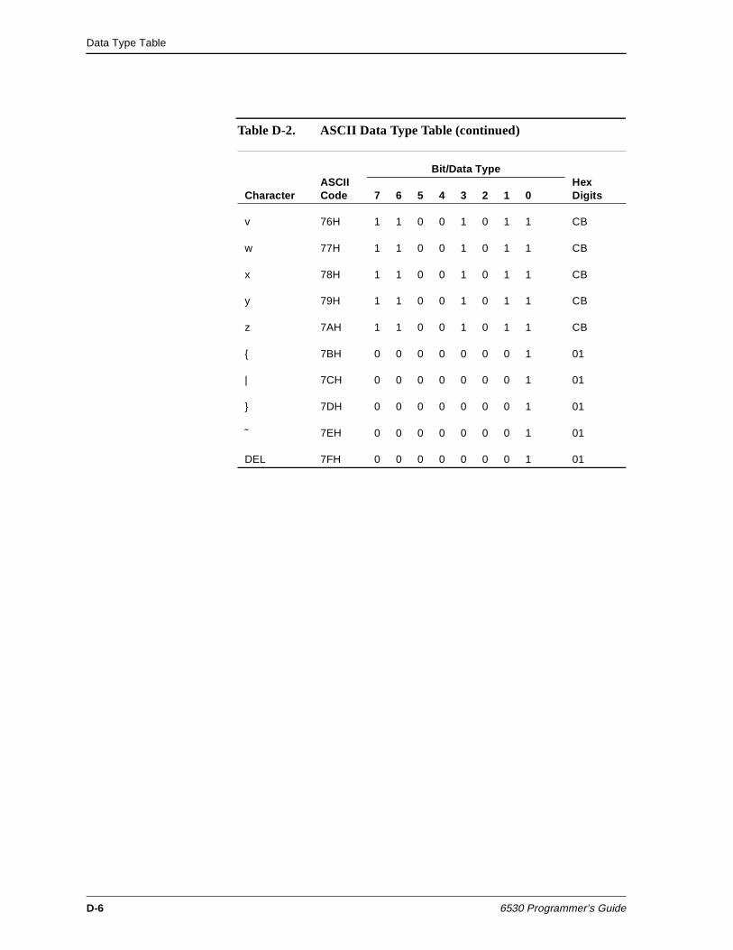
Data Type Table
D-6 6530 Programmer’s Guide
v 76H 1 1 0 0 1 0 1 1 CB
w 77H 1 1 0 0 1 0 1 1 CB
x 78H 1 1 0 0 1 0 1 1 CB
y 79H 1 1 0 0 1 0 1 1 CB
z 7AH 1 1 0 0 1 0 1 1 CB
{ 7BH 0 0 0 0 0 0 0 1 01
| 7CH 0 0 0 0 0 0 0 1 01
} 7DH 0 0 0 0 0 0 0 1 01
˜ 7EH 0 0 0 0 0 0 0 1 01
DEL 7FH 0 0 0 0 0 0 0 1 01
Table D-2. ASCII Data Type Table (continued)
Character ASCII Code
Bit/Data TypeHex Digits 7 6 5 4 3 2 1 0
6530 Programmer’s Guide Index-1
Index
Symbols! - configuration message 3-57
(BS) backspace 3-18
(CR) 3-41
(CR) carriage return 3-18
(DC1) 3-69
(DC1) set buffer address 3-15, 3-42
(DC2) 3-77
to start extended data compression 3-73
(DC3 set cursor address 3-14
(DC4) start limited data compression 3-72
(Esc 3-70
(Esc - ’) start enhanced color field 3-33
(Esc - 0) write to Aux1 or Aux2 device 3-78
(Esc - c) set string configuration parameter 3-62
(Esc - d) read string configuration parameter 3-61
(Esc - D) set cursor address extended 3-14
(Esc - e) get machine name 3-76
(Esc - f) get current directory and redirection information 3-76
(Esc - g) read VTLAUNCH 6530 configuration parameter 3-63
(Esc - I) clear memory to spaces extended 3-49
(Esc - i) RTM control 3-65
(Esc - J) read with address extended 3-46
(Esc - K) read with address all extended 3-47
(Esc - m) set EM3270 mode 3-67
(Esc - s) define/update variable table 3-89
(Esc - V) load and execute an operating system program 3-82
(Esc - W) report exec return code 3-83
(Esc - x) set 6530 color mapping 3-32
(Esc - z) terminate remote 6530 operation 3-92
(Esc :) select page 3-12
(Esc ;) display page 3-11
(Esc <) read whole page (EM3720 mode) 3-69
(Esc <) read whole page / buffer 3-44
(Esc =) read with address 3-45
(Esc =) read with address (EM3270 mode) 3-69, 3-70
(Esc >) reset modified data tags 3-38
(Esc ?) "e" parameter 3-59
(Esc ?) read terminal configuration 3-51, 3-57
(Esc @) delay one second 3-90
(Esc [) start field extended 3-37
(Esc ]) read with address all 3-46, 3-69, 3-70
(Esc ]) read with address all (EM3270 mode) 3-69, 3-70
(Esc ^) read terminal status 3-74
(Esc _) read full revision level 3-75
Index
Index-2 6530 Programmer’s Guide
(Esc {) write to file or device name 3-79
(Esc }) write/read to file or device name 3-80
(Esc 0) print page 3-77
(Esc 1) set tab 3-19
(Esc 2) clear tab 3-19
(Esc 3) clear all tabs 3-19
(Esc 6) set video attributes 2-18, 3-2, 3-27, 3-33, 3-37, 3-38, 3-41, 3-42
(Esc 8) Set 40-character line width 3-40
(Esc 9) Set 80-character line width 3-40
(Esc A) cursor up 3-17
(Esc a) read cursor address 3-15
(Esc b) unlock keyboard 3-91
(Esc C) cursor right 3-17
(Esc c) lock keyboard 3-91
(Esc d) simulate function key 3-91
(Esc F) cursor home down 3-18
(Esc f) disconnect modem 3-84
(Esc H) cursor home 3-18
(Esc I) clear memory to spaces 3-48
(Esc J) erase to end of page 3-49
(Esc K) erase to end of line/field 3-49
(Esc L) insert line 3-50
(Esc M) delete line 3-50
(Esc N) disable local line editing 3-91
(Esc O) insert character 3-51
(Esc o) write to message field 3-92
(Esc P) delete character 3-51
(Esc Q) read screen with all attributes 3-34
(Esc q) reinitialize 2-50, 3-92
(Esc r) define data type table 3-39
(Esc t) Set 40-character screen width 3-40
(Esc v) set terminal configuration 3-52
(Esc W) enter protect submode 3-35
(Esc X) exit protect submode 3-36
(Esc x) set I/O device configuration 3-60
(Esc y) read I/O device configuration 3-60
(Esc z) execute self test 3-93
(Esc-r) Define Extended Data Type Table 3-40
(ETX) 3-77
(FS) define field attribute 3-84
(GS) start field 3-37
table of bit patterns 3-37
(HT) horizontal tab 3-18
(LF) line feed 3-17
(S0) switch out to G1 character set 3-93
(S1) shift in to G0 character set 3-93
start field extended (Esc 3-6
Numerics3270 style attribute pairs 3-35
6100 Communications Subsystem (CSS) 1-11
6600 Intelligent Cluster Controller 1-11
Aaddressing
extended 2-5, 3-13
normal 2-5, 3-13
type of addressing used 2-6
AID (alternate input device) 3-6
Alternate Input Device (AID) 1-7
Alternate input device attribute 1-7
apostrophe 3-76
application programming example 4-5
Arrow keys in EM3270 mode 3-68
ASCII character set A1
ASCII control characters 1-8, A1
Index
6530 Programmer’s Guide Index-3
ASCII graphics characters 1-8
Attribute
video 1-7
auto-tab disable 3-5
Auto-tab disable attribute 1-7
AUX2 device name parameter 1-16
AWAITIO 4-4
BBack Tab (Esc i) 3-19
background color 2-24, 3-34
backspace (BS) 2-8, 3-18
Backtab key in EM3270 mode 3-69
Baud rate parameter 1-17
bell (BEL) 2-48, 3-84
Bell volume parameter 1-17
block mode 3-1, 3-7
memory organization 1-5
nonprotect submode 1-6
protect submode 1-6
CCANCELREQ 4-4
carriage return (CR) 3-18
carriage return (CR, 0DH) 2-8
CGA 2-24, 3-34
Character Codes 1-8
Character set ranges 1-8
Character size parameter 1-17
Character, displayable 1-3
clear all tabs (Esc 3) 2-9, 3-19
clear display memory 2-10, 3-48
clear memory to spaces 2-10, 3-48
clear memory to spaces extended 3-49
erase to end of line 2-11
erase to end of line/field 3-49
erase to end of memory 2-10
erase to end of page 3-49
clear memory to spaces (Esc I) 2-10, 3-48
clear memory to spaces extended (Esc - I) 3-49
clear tab (Esc 2) 2-9, 3-19
CLOSE 4-4
color enhancement query (Esc ?) 2-24
color mapping parameters
color mapping 2-15, 3-24
normal background color 2-15, 3-24
normal foreground color 2-15, 3-24
normal intensity 2-15, 3-24
underline background color 2-16, 3-25
underline foreground color 2-15, 3-24
underline mapping 2-16, 3-25
communications
CCS (Communications Control System) 4-2
NonStop / 6530 4-2
communications configurations 1-11
compression 3-72
(DC2) to start extended data compression 3-73
(DC4) start limited data compression 3-72
extended data compression 3-73
limited data compression 3-73
configuration message 3-57
configuration parameters 1-10, 2-24
6530 responses to read VTLAUNCH configuration parameter 2-34
AUX2 device name 1-16
baud rate 1-17
bell volume 1-17
character size 1-17
host name 1-18
keyboard 1-19
local transmit column 1-20
Index
Index-4 6530 Programmer’s Guide
normal intensity 1-20
packet blocking 1-21
parity 1-21
print form feed 1-21
print line terminator 1-22
read I/O device configuration 2-31
read string configuration parameter 2-32
read terminal configuration 2-30
read VTLAUNCH 6530 configuration parameter 2-33
resource name 1-22
screen saver 1-22
session name 1-23
set I/O device configuration 2-31
set string configuration parameter 2-33
set terminal configuration 2-30
SPS 1-23
transmit line 1-23
window name 1-23
configuration values 3-51
read field-selectable color configuration 3-59
read I/O device configuration 3-60
read string configuration parameter 3-61
read VTLAUNCH 6530 configuration parameter 3-63
set I/O device configuration 3-60
set string configuration parameter 3-62
connectivity
host / terminal 4-2
CONTROL 4-4
control character 1-3
Esc as header 3-6
control codes 2-2, 3-6
CONTROL procedure call 1-15
conversational mode 2-1
CTRL-NEXT PAGE 1-2
CTRL-PREV PAGE 1-2
Ctrl-Scroll Lock (break signal to host) 2-54
cursor and buffer addressing 3-15
extended addressing 3-13
normal addressing 3-13
read cursor address 3-15
set buffer address extended 3-16
set cursor address (DC3) 3-14
set cursor address extended 3-14
cursor home (Esc H) 2-8, 3-18
cursor location 2-5, 3-11
in protected field 3-16
read cursor address 2-6, 3-15
set buffer address 3-15
set buffer address extended 3-16
set cursor address 2-6, 3-14
set cursor address extended 2-6, 3-14
cursor movement 2-7, 3-16
back tab 3-19
backspace 2-8, 3-18
carriage return 2-8, 3-18
cursor home 2-8, 3-18
cursor home down (Esc F) 2-8, 3-18
cursor right 2-8, 3-17
cursor up 2-7, 3-17
horizontal tab 2-8
horizontal tab (HT) 3-18
in EM3270 mode 3-68
line feed 2-8, 3-17
cursor right (Esc C) 2-8, 3-17
cursor up (Esc A) 2-7, 3-17
Ddata attributes 3-4
alternate input device 1-7, 3-6
auto-tab disable 1-7
data type 1-7
(GS) start field bit patterns 3-37
modified data tag 1-7
protect 1-7
redefining data types D2
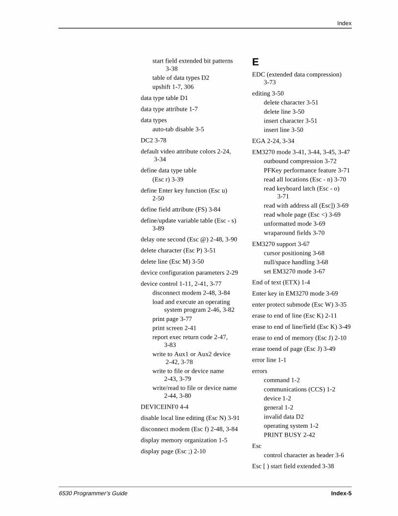
Index
6530 Programmer’s Guide Index-5
start field extended bit patterns 3-38
table of data types D2
upshift 1-7, 306
data type table D1
data type attribute 1-7
data types
auto-tab disable 3-5
DC2 3-78
default video attribute colors 2-24, 3-34
define data type table
(Esc r) 3-39
define Enter key function (Esc u) 2-50
define field attribute (FS) 3-84
define/update variable table (Esc - s) 3-89
delay one second (Esc @) 2-48, 3-90
delete character (Esc P) 3-51
delete line (Esc M) 3-50
device configuration parameters 2-29
device control 1-11, 2-41, 3-77
disconnect modem 2-48, 3-84
load and execute an operating system program 2-46, 3-82
print page 3-77
print screen 2-41
report exec return code 2-47, 3-83
write to Aux1 or Aux2 device 2-42, 3-78
write to file or device name 2-43, 3-79
write/read to file or device name 2-44, 3-80
DEVICEINF0 4-4
disable local line editing (Esc N) 3-91
disconnect modem (Esc f) 2-48, 3-84
display memory organization 1-5
display page (Esc ;) 2-10
EEDC (extended data compression)
3-73
editing 3-50
delete character 3-51
delete line 3-50
insert character 3-51
insert line 3-50
EGA 2-24, 3-34
EM3270 mode 3-41, 3-44, 3-45, 3-47
outbound compression 3-72
PFKey performance feature 3-71
read all locations (Esc - n) 3-70
read keyboard latch (Esc - o) 3-71
read with address all (Esc]) 3-69
read whole page (Esc <) 3-69
unformatted mode 3-69
wraparound fields 3-70
EM3270 support 3-67
cursor positioning 3-68
null/space handling 3-68
set EM3270 mode 3-67
End of text (ETX) 1-4
Enter key in EM3270 mode 3-69
enter protect submode (Esc W) 3-35
erase to end of line (Esc K) 2-11
erase to end of line/field (Esc K) 3-49
erase to end of memory (Esc J) 2-10
erase toend of page (Esc J) 3-49
error line 1-1
errors
command 1-2
communications (CCS) 1-2
device 1-2
general 1-2
invalid data D2
operating system 1-2
PRINT BUSY 2-42
Esc
control character as header 3-6
Esc [ ) start field extended 3-38
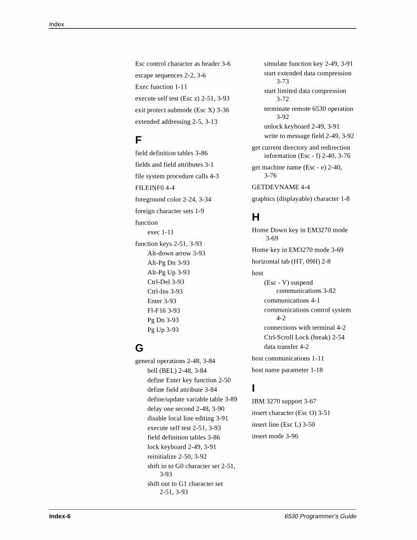
Index
Index-6 6530 Programmer’s Guide
Esc control character as header 3-6
escape sequences 2-2, 3-6
Exec function 1-11
execute self test (Esc z) 2-51, 3-93
exit protect submode (Esc X) 3-36
extended addressing 2-5, 3-13
Ffield definition tables 3-86
fields and field attributes 3-1
file system procedure calls 4-3
FILEINF0 4-4
foreground color 2-24, 3-34
foreign character sets 1-9
function
exec 1-11
function keys 2-51, 3-93
Alt-down arrow 3-93
Alt-Pg Dn 3-93
Alt-Pg Up 3-93
Ctrl-Del 3-93
Ctrl-Ins 3-93
Enter 3-93
Fl-F16 3-93
Pg Dn 3-93
Pg Up 3-93
Ggeneral operations 2-48, 3-84
bell (BEL) 2-48, 3-84
define Enter key function 2-50
define field attribute 3-84
define/update variable table 3-89
delay one second 2-48, 3-90
disable local line editing 3-91
execute self test 2-51, 3-93
field definition tables 3-86
lock keyboard 2-49, 3-91
reinitialize 2-50, 3-92
shift in to G0 character set 2-51, 3-93
shift out to G1 character set 2-51, 3-93
simulate function key 2-49, 3-91
start extended data compression 3-73
start limited data compression 3-72
terminate remote 6530 operation 3-92
unlock keyboard 2-49, 3-91
write to message field 2-49, 3-92
get current directory and redirection information (Esc - f) 2-40, 3-76
get machine name (Esc - e) 2-40, 3-76
GETDEVNAME 4-4
graphics (displayable) character 1-8
HHome Down key in EM3270 mode
3-69
Home key in EM3270 mode 3-69
horizontal tab (HT, 09H) 2-8
host
(Esc - V) suspend communications 3-82
communications 4-1
communications control system 4-2
connections with terminal 4-2
Ctrl-Scroll Lock (break) 2-54
data transfer 4-2
host communications 1-11
host name parameter 1-18
IIBM 3270 support 3-67
insert character (Esc O) 3-51
insert line (Esc L) 3-50
insert mode 3-96
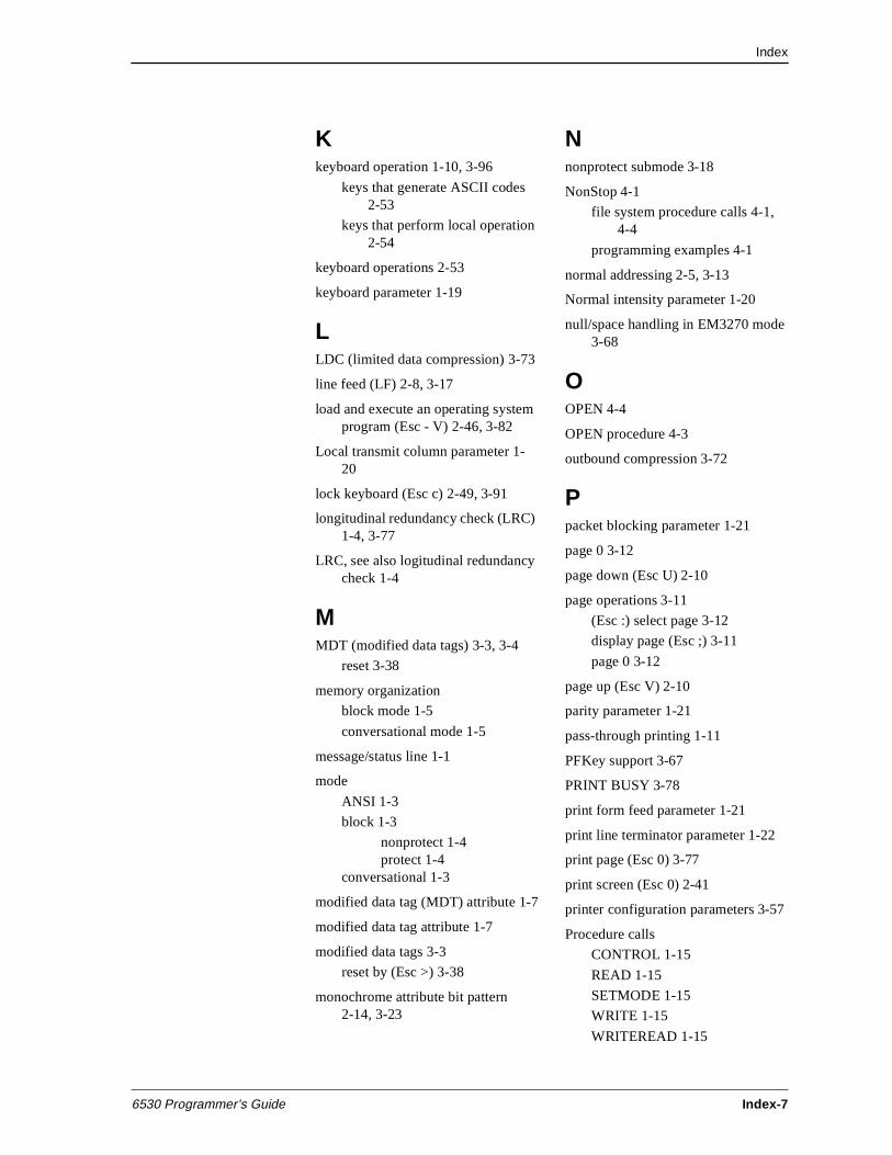
Index
6530 Programmer’s Guide Index-7
Kkeyboard operation 1-10, 3-96
keys that generate ASCII codes 2-53
keys that perform local operation 2-54
keyboard operations 2-53
keyboard parameter 1-19
LLDC (limited data compression) 3-73
line feed (LF) 2-8, 3-17
load and execute an operating system program (Esc - V) 2-46, 3-82
Local transmit column parameter 1-20
lock keyboard (Esc c) 2-49, 3-91
longitudinal redundancy check (LRC) 1-4, 3-77
LRC, see also logitudinal redundancy check 1-4
MMDT (modified data tags) 3-3, 3-4
reset 3-38
memory organization
block mode 1-5
conversational mode 1-5
message/status line 1-1
mode
ANSI 1-3
block 1-3
nonprotect 1-4protect 1-4
conversational 1-3
modified data tag (MDT) attribute 1-7
modified data tag attribute 1-7
modified data tags 3-3
reset by (Esc >) 3-38
monochrome attribute bit pattern2-14, 3-23
Nnonprotect submode 3-18
NonStop 4-1
file system procedure calls 4-1, 4-4
programming examples 4-1
normal addressing 2-5, 3-13
Normal intensity parameter 1-20
null/space handling in EM3270 mode 3-68
OOPEN 4-4
OPEN procedure 4-3
outbound compression 3-72
Ppacket blocking parameter 1-21
page 0 3-12
page down (Esc U) 2-10
page operations 3-11
(Esc :) select page 3-12
display page (Esc ;) 3-11
page 0 3-12
page up (Esc V) 2-10
parity parameter 1-21
pass-through printing 1-11
PFKey support 3-67
PRINT BUSY 3-78
print form feed parameter 1-21
print line terminator parameter 1-22
print page (Esc 0) 3-77
print screen (Esc 0) 2-41
printer configuration parameters 3-57
Procedure calls
CONTROL 1-15
READ 1-15
SETMODE 1-15
WRITE 1-15
WRITEREAD 1-15
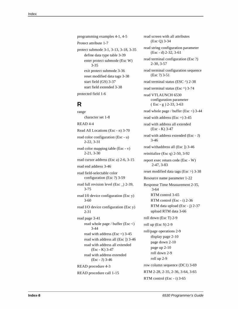
Index
Index-8 6530 Programmer’s Guide
programming examples 4-1, 4-5
Protect attribute 1-7
protect submode 3-1, 3-13, 3-18, 3-35
define data type table 3-39
enter protect submode (Esc W) 3-35
exit protect submode 3-36
reset modified data tags 3-38
start field (GS) 3-37
start field extended 3-38
protected field 1-6
Rrange
character set 1-8
READ 4-4
Read All Locations (Esc - n) 3-70
read color configuration (Esc - u) 2-22, 3-31
read color mapping table (Esc - v) 2-21, 3-30
read cursor address (Esc a) 2-6, 3-15
read end address 3-46
read field-selectable color configuration (Esc ?) 3-59
read full revision level (Esc _) 2-39, 3-75
read I/0 device configuration (Esc y) 3-60
read I/O device configuration (Esc y) 2-31
read page 3-41
read whole page / buffer (Esc <) 3-44
read with address (Esc =) 3-45
read with address all (Esc ]) 3-46
read with address all extended (Esc - K) 3-47
read with address extended(Esc - J) 3-46
READ procedure 4-3
READ procedure call 1-15
read screen with all attributes (Esc Q) 3-34
read string configuration parameter (Esc - d) 2-32, 3-61
read terminal configuration (Esc ?) 2-30, 3-57
read terminal configuration sequence (Esc ?) 3-51
read terminal status (ESC ^) 2-38
read terminal status (Esc ^) 3-74
read VTLAUNCH 6530 configuration parameter ( Esc - g ) 2-33, 3-63
read whole page / buffer (Esc <) 3-44
read with address (Esc =) 3-45
read with address all extended(Esc - K) 3-47
read with address extended (Esc - J) 3-46
read withaddress all (Esc ]) 3-46
reinitialize (Esc q) 2-50, 3-92
report exec return code (Esc - W) 2-47, 3-83
reset modified data tags (Esc >) 3-38
Resource name parameter 1-22
Response Time Measurement 2-35, 3-64
RTM control 3-65
RTM control (Esc - i) 2-36
RTM data upload (Esc - j) 2-37
upload RTM data 3-66
roll down (Esc T) 2-9
roll up (Esc S) 2-9
roll/page operations 2-9
display page 2-10
page down 2-10
page up 2-10
roll down 2-9
roll up 2-9
row column sequence (DC1) 3-69
RTM 2-28, 2-35, 2-36, 3-64, 3-65
RTM control (Esc - i) 3-65
Index
6530 Programmer’s Guide Index-9
Sscreen format 1-1
cursor location 2-5
screen printing 1-11
screen saver parameter 1-22
session name parameter 1-23
set 40-character line width (Esc 8) 3-40
set 40-character screen width (Esc t) 3-40
set 6530 color mapping (Esc - x) 3-32
set 80-character line width (Esc 9) 3-40
set buffer address (DC1) 3-15, 3-42
set buffer address extended (Esc - C) 3-16
set color configuration (Esc - t) 2-23, 3-32
set Ctrl-Ins and Ctrl-Del to function keys 3-36
set cursor address (DC3, 13H) 2-6, 3-14
set cursor address extended (Esc - D) 2-6, 3-14
set EM3270 mode (Esc - m) 3-67
set I/0 device configuration (Esc x) 3-60
set I/O device configuration (Esc x) 2-31
set string configuration parameter (Esc - c) 2-33, 3-62
set tab (Esc 1) 2-9, 3-19
set terminal configuration (Esc v) 2-30
set terminal configuration sequence (Esc v) 3-52
set video attributes (Esc 6) 2-14, 3-23
set video prior condition register (Esc 7) 2-15, 3-24
set/reset color map table (Esc - q) 2-19, 3-28
SETMODE procedure 4-4
SETMODE procedure call 1-15
SETMODENOWAIT 4-4
Setting parameters from the application 1-16
shift in to G0 character set (S1) 2-51, 3-93
shift out to G1 character set (S0) 2-51, 3-93
SI 3-7
simulate function key (Esc d) 2-49, 3-91
SO 3-7
SPS parameter 1-23
start enhanced color field (Esc ’) 3-33
start field extended (Esc [ ) 3-38
start field extended (Esc [) 3-37
start of header (SOH) 1-4
start of text (STX) 1-4
status area 1-2
status information 2-38, 3-74
get current directory and redirection information 2-40, 3-76
get machine name 2-40, 3-76
read full revision level 2-39, 3-75
read terminal status 2-38, 3-74
status line 1-2
string values 3-62
SYSGEN 4-2
TTab key in EM3270 mode 3-68
tab settings 2-9
clear all tabs 2-9, 3-19
clear tab 2-9, 3-19
set tab 2-9
tab stops 3-19
Index
Index-10 6530 Programmer’s Guide
tables
ASCII control characters A1
data attributes summary 3-5
data types D2
define data type 3-39
EM3270 mode terminal return values 3-58
field definitions formats 3-86
file system procedure calls (NonStop) 4-4
fixed field definitions table - assigned by EM3270 3-86
function key codes 2-52, 3-94
keyboard operation 3-96
keys that generate ASCII codes 2-53
printer configuration parameters 3-57
start field extended attributes 3-38
terminal configuration parameters 3-52
variable field definitions 3-88
video attribute bit patterns for monochrome display 2-13, 3-22
terminate remote 6530 operation (Esc - z) 3-92
TERMPROCESS 4-2, 4-3
The Set Terminal Configuration sequence (Esc v) 3-52
transition from protect to nonprotect submode 3-91
Transmit line parameter 1-23
Uunlock keyboard (Esc b) 2-49, 3-91
upload RTM data (Esc - j)
(Esc - j) upload RTM data 3-66
upshift 3-6
Upshift attribute 1-7
VVGA 2-24, 3-34
mode 3 2-24, 3-34
video attribute
video attributes 2-11, 3-20
blinking or nonblinking 1-7
color enhancement query 2-24
default colors 2-24, 3-34
following (GS) control character 3-37
implementation limits 2-24, 3-34
monochrome attribute bit pattern 2-14, 3-23
normal or alternate intensity 1-7
normal or invisible (not displayed) 1-7
normal or reverse video 1-7
normal or underscored 1-7
read color configuration 2-22, 3-31
read color mapping table 2-21, 3-30
read screen with all attributes 3-34
set 6530 color mapping 3-32
set color configuration 2-23, 3-32
set video attributes 2-14, 3-23
set video prior condition register 2-15, 3-24
set/reset color map table 2-19, 3-28
start enhanced color field 3-33
Virtual Terminal Launch (VTLAUNCH) 2-33
WWindow name parameter 1-23
WRITE 4-4
Write operation 1-11
WRITE procedure 4-3
WRITE procedure call 1-15
write to Aux1 or Aux2 device (Esc - 0) 2-42
write to Auxl or Aux2 device (Esc - 0) 3-78
Index
6530 Programmer’s Guide Index-11
write to file or device name (Esc {) 2-43, 3-79
write to message field (Esc o) 2-49, 3-92
write/read operation 4-3
write/read to file or device name (Esc }) 2-44, 3-80
Writeread operation 1-11
WRITEREAD procedure 4-4
WRITEREAD procedure call 1-15

Index
Index-12 6530 Programmer’s Guide

Tandem Computers Incorporated14231 Tandem BoulevardAustin, Texas 78728-6699 USA
Part Number 131921