Embed Size (px)
Citation preview
6.5.3.2 MBR Filtrate Pump Operation
The MBR filtrate pump draws flow from the membrane modules in the membrane basins, through the membranes and pumps to the UV building. Each MBR train has a dedicated MBR filtrate pump. A redundant pump is provided as a spare on the shelf, when needed. In some cases these pumps are called out as permeate pumps on the SCADA screens. The permeate pumps and the filtrate pumps are the same pumps, but the preferred name for the pumps is filtrate pumps.
MBR Process Control Screens The MBR filtrate pumps are controlled through SCADA from the MBR Process screens. The access to these screens is discussed in the following sections.
MBR Process Main Screen
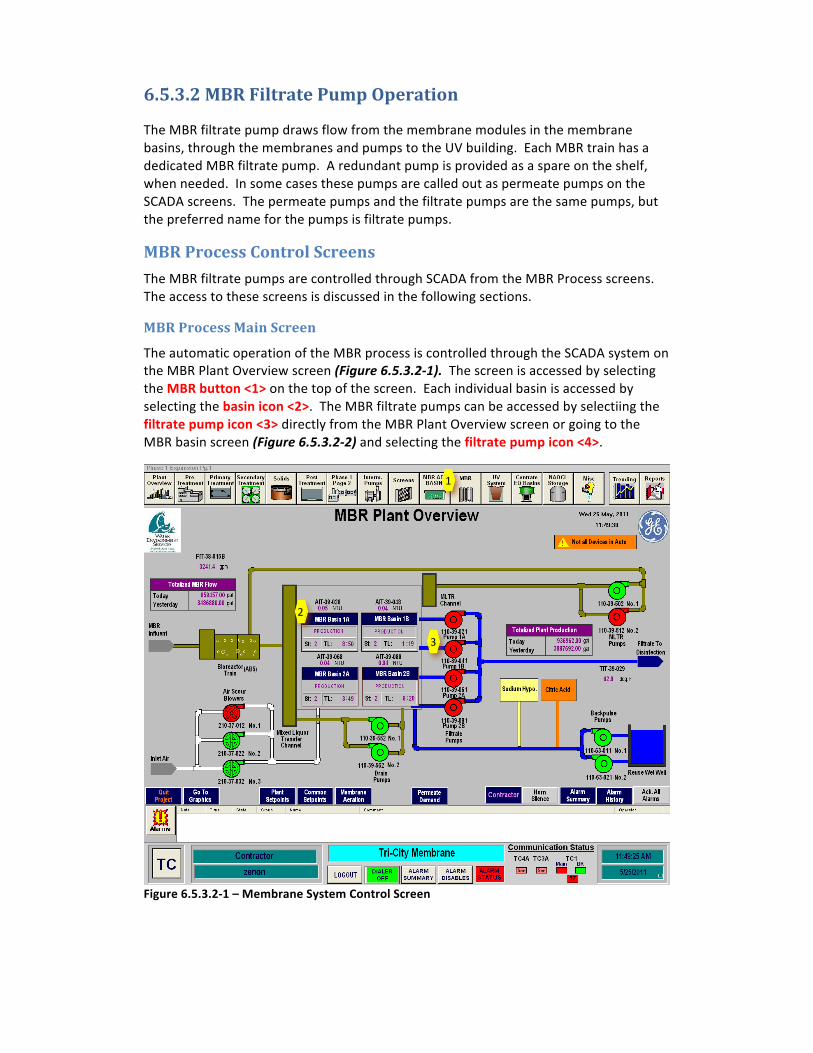
The automatic operation of the MBR process is controlled through the SCADA system on the MBR Plant Overview screen (Figure 6.5.3.2-‐1). The screen is accessed by selecting the MBR button <1> on the top of the screen. Each individual basin is accessed by selecting the basin icon <2>. The MBR filtrate pumps can be accessed by selectiing the filtrate pump icon <3> directly from the MBR Plant Overview screen or going to the MBR basin screen (Figure 6.5.3.2-‐2) and selecting the filtrate pump icon <4>.
Figure 6.5.3.2-‐1 – Membrane System Control Screen
1
2
3
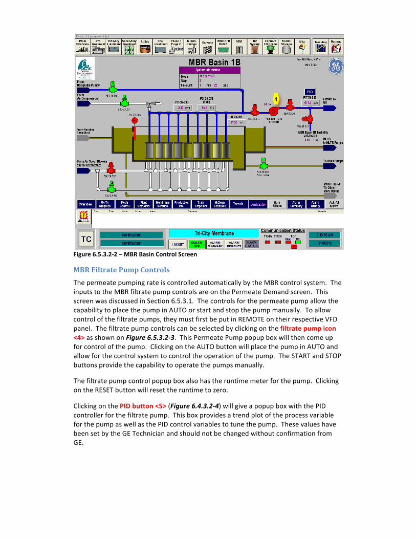
Figure 6.5.3.2-‐2 – MBR Basin Control Screen
MBR Filtrate Pump Controls
The permeate pumping rate is controlled automatically by the MBR control system. The inputs to the MBR filtrate pump controls are on the Permeate Demand screen. This screen was discussed in Section 6.5.3.1. The controls for the permeate pump allow the capability to place the pump in AUTO or start and stop the pump manually. To allow control of the filtrate pumps, they must first be put in REMOTE on their respective VFD panel. The filtrate pump controls can be selected by clicking on the filtrate pump icon <4> as shown on Figure 6.5.3.2-‐3. This Permeate Pump popup box will then come up for control of the pump. Clicking on the AUTO button will place the pump in AUTO and allow for the control system to control the operation of the pump. The START and STOP buttons provide the capability to operate the pumps manually.
The filtrate pump control popup box also has the runtime meter for the pump. Clicking on the RESET button will reset the runtime to zero.
Clicking on the PID button <5> (Figure 6.4.3.2-‐4) will give a popup box with the PID controller for the filtrate pump. This box provides a trend plot of the process variable for the pump as well as the PID control variables to tune the pump. These values have been set by the GE Technician and should not be changed without confirmation from GE.
4
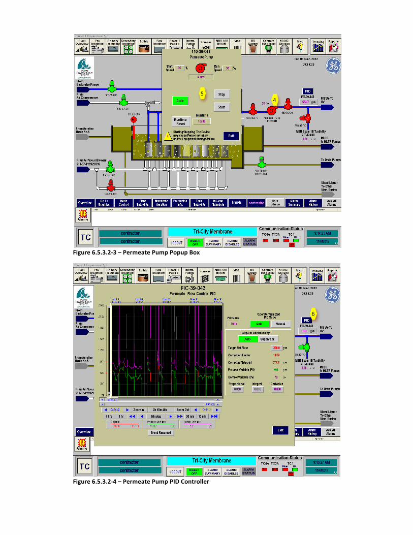
Figure 6.5.3.2-‐3 – Permeate Pump Popup Box
Figure 6.5.3.2-‐4 – Permeate Pump PID Controller
4 5
6
Permeate (Filtrate) Flow Transmitter
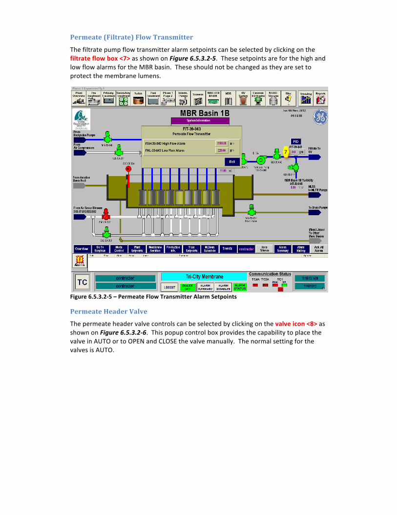
The filtrate pump flow transmitter alarm setpoints can be selected by clicking on the filtrate flow box <7> as shown on Figure 6.5.3.2-‐5. These setpoints are for the high and low flow alarms for the MBR basin. These should not be changed as they are set to protect the membrane lumens.
Figure 6.5.3.2-‐5 – Permeate Flow Transmitter Alarm Setpoints
Permeate Header Valve
The permeate header valve controls can be selected by clicking on the valve icon <8> as shown on Figure 6.5.3.2-‐6. This popup control box provides the capability to place the valve in AUTO or to OPEN and CLOSE the valve manually. The normal setting for the valves is AUTO.
7
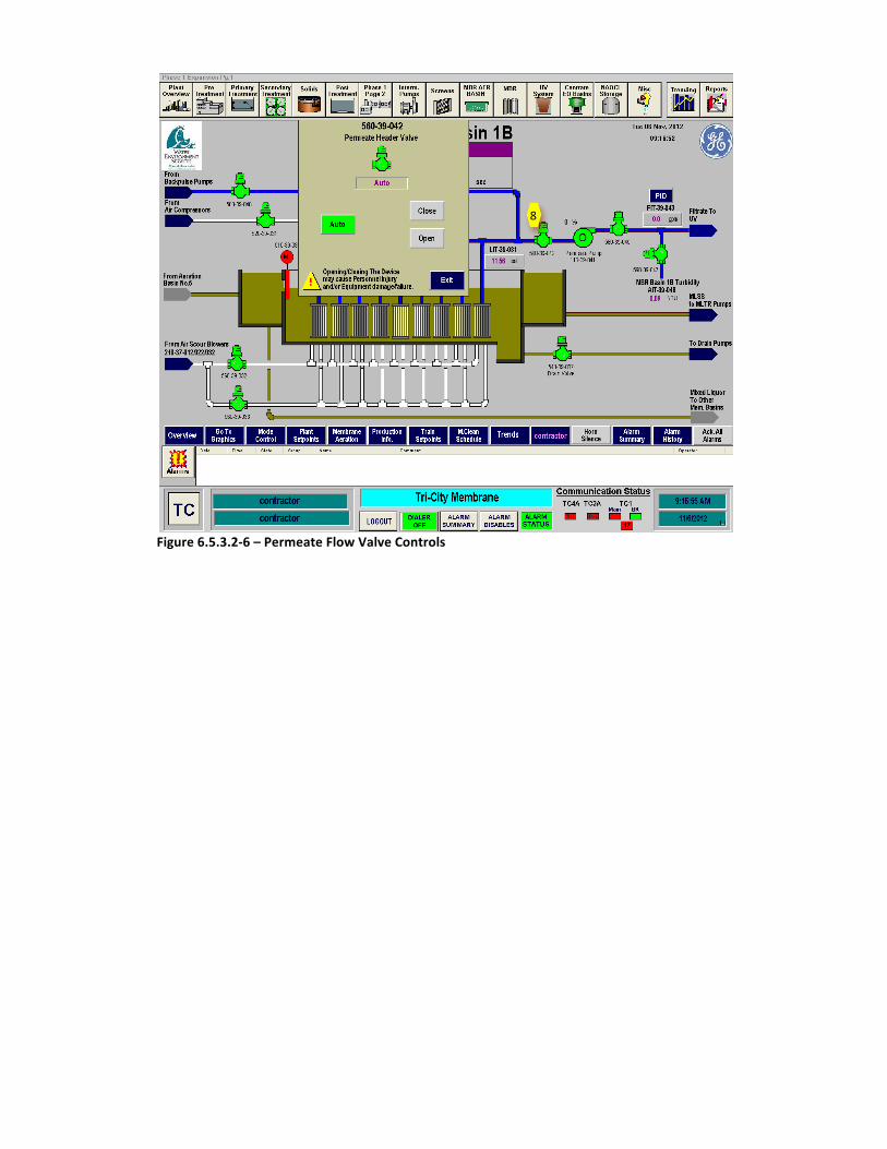
Figure 6.5.3.2-‐6 – Permeate Flow Valve Controls
8